JP6538616B2 - Gaming machine - Google Patents
Gaming machine Download PDFInfo
- Publication number
- JP6538616B2 JP6538616B2 JP2016114187A JP2016114187A JP6538616B2 JP 6538616 B2 JP6538616 B2 JP 6538616B2 JP 2016114187 A JP2016114187 A JP 2016114187A JP 2016114187 A JP2016114187 A JP 2016114187A JP 6538616 B2 JP6538616 B2 JP 6538616B2
- Authority
- JP
- Japan
- Prior art keywords
- special symbol
- game
- random number
- symbol
- special
- Prior art date
- Legal status (The legal status is an assumption and is not a legal conclusion. Google has not performed a legal analysis and makes no representation as to the accuracy of the status listed.)
- Active
Links
Images


Description
本発明は、遊技媒体を用いた遊技機に係わり、特に遊技者が操作可能な操作手段を備えた遊技機に関するものである。 The present invention relates to a gaming machine using gaming media, and more particularly to a gaming machine provided with operation means operable by a player.
パチンコ機などの遊技機では、液晶画面を備える画像表示装置や、音声出力装置(スピーカー)、電動役物などを用いた各種の演出が行われ、遊技者の興趣を高める工夫がなされている。
例えば、始動口への遊技球の入球を契機として行われた図柄の抽選結果に基づいて演出パターンが決定され、この演出パターンに応じて画像表示装置に演出画像が表示されるとともに、音声出力装置からは音楽や効果音が流れる演出が一般的に行われている。
さらに、大当たり期待度の高い演出では特定の効果音が流れたり、それとともに特定の電動役物が動作したりすることで、遊技者はそれらの情報をヒントとして現在の変動の期待度を判断したりするなど遊技をより楽しむことができる。
In a gaming machine such as a pachinko machine, various effects are performed using an image display device provided with a liquid crystal screen, an audio output device (speaker), a motorized role, etc., to improve the player's interest.
For example, the effect pattern is determined based on the lottery result of the symbol performed with the game ball entering the starting opening as a trigger, and the effect image is displayed on the image display device according to the effect pattern, and the sound is output Generally, music and sound effects flow from the device.
Furthermore, in the case of the jackpot expectation degree, a specific sound effect flows, and a certain motorized part operates along with it, the player judges the expectation degree of the present fluctuation with the information as a hint. You can enjoy playing more games.
このような遊技機において、昨今では、操作手段としての十字キーや演出ボタンを用いて、液晶画面に表示される演出をカスタマイズしたり(例えば、特許文献1)、遊技外の情報を閲覧したりすることを可能としたものがある。
これにより、遊技者は、図柄の変動結果が大当たりになるか否かといった楽しみ以外に、自分好みにカスタマイズされた演出を楽しむことができたり、あるいは遊技機のモチーフとなるコンテンツについての付加的な情報を知り得たりするため、遊技の興趣を一段と高めることが出来る。
In such gaming machines, nowadays, the cross key or effect button as an operation means is used to customize the effect displayed on the liquid crystal screen (for example, see Patent Document 1) or to browse information outside the game. There is something that makes it possible.
In this way, the player can enjoy an effect customized to his liking, in addition to the enjoyment as to whether or not the variation result of the symbol is a big hit, or an additional content for the motif of the gaming machine. In order to know the information, it is possible to further enhance the interest of the game.
本発明は、操作手段を用いた遊技者の操作によって行われる新たな演出態様によって遊技者の興趣を向上させることが可能な遊技機を提供することを目的とする。 An object of the present invention is to provide a gaming machine capable of improving the interest of a player by a new effect mode performed by the operation of the player using the operation means.
上記の課題を解決するために、本発明の第1の形態は、図柄を変動表示させる図柄変動表示手段と、遊技に係わる演出画像を記憶する記憶手段と、該記憶手段に記憶される前記演出画像を表示装置に表示する制御を行う表示制御手段と、遊技者が操作可能な第1の操作手段及び第2の操作手段と、通常遊技状態と、該通常遊技状態よりも遊技者に有利な特定遊技状態と、の何れかに遊技状態を制御可能な遊技状態制御手段と、を備え、前記図柄変動表示手段は、一の変動表示の終了後、所定の確定期間が経過した後に次の変動表示を開始可能であり、前記演出画像は、前記第1操作手段の操作に応じて表示される第1の演出画像と、前記第2操作手段の操作に応じて表示される第1の演出画像とは異なる第2の演出画像と、を含み、前記表示制御手段は、前記遊技状態が前記通常遊技状態又は前記特定遊技状態の何れであっても、前記変動表示中における前記第1の操作手段による操作が行われたとき、当該操作に応じて第1の演出画像を所定の順序に従って前記表示装置に表示させるとともに、前記変動表示中における第2の操作手段による操作が行われたとき、当該操作に応じて第2の演出画像を所定の順序に従って、前記表示装置に表示させ、前記表示制御手段により表示された第1の演出画像及び第2の演出画像に関連した情報を夫々記憶する情報記憶手段を備え、前記表示制御手段は、前記変動表示中における前記第1の操作手段又は前記第2の操作手段による操作に応じて、前記情報記憶手段に記憶した前記情報に基づいて第1の演出画像又は第2の演出画像を夫々表示させ、前記変動表示の終了後、前記確定期間中に第1の演出画像又は第2の演出画像の表示を継続することを特徴とする。
In order to solve the above problems, according to a first aspect of the present invention, there is provided a symbol variation display means for varyingly displaying symbols, a storage means for storing an effect image relating to a game, and the effect stored in the storage means Display control means for performing control to display an image on a display device, first operation means and second operation means operable by the player, normal gaming state, and advantageous to the player over the normal gaming state The game state control means capable of controlling the game state to any of the specific game state, and the symbol change display means is configured to change the next change after a predetermined determination period has elapsed after the end of one change display. The display can be started, and the effect image is a first effect image displayed according to the operation of the first operation means, and a first effect image displayed according to the operation of the second operation means anda different second effect image and the display Control means, be either the game mode of the normal game state or the specific game state, when the operation by the first operating means during said variable display is performed, first in response to the
以上のように構成したので、本発明によれば、遊技者の興趣を高めることが可能な遊技機を実現することが出来る。 Since it comprised as mentioned above, according to this invention, the game machine which can raise the interest of a player can be implement | achieved.
以下、本発明を図面に示した実施の形態により詳細に説明する。
<遊技機の構成>
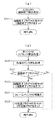
図1は、本実施形態に係る遊技機の一例を示した正面図、図2は、パチンコ遊技機1の一部を示す概略平面図、図3は、本実施形態に係る遊技機の裏面側の一例を示した斜視図、図4は、本実施形態に係る遊技機に備えられている遊技制御装置の構成を示したブロック図である。
Hereinafter, the present invention will be described in detail by embodiments shown in the drawings.
<Configuration of gaming machine>
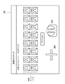
FIG. 1 is a front view showing an example of a gaming machine according to this embodiment, FIG. 2 is a schematic plan view showing a part of
この図1に示す遊技機1には、遊技ホールの島構造体に取付けられる外枠2に内枠(開閉枠)3が開閉可能に装着され、この内枠3にガラス枠4が開閉可能に装着されている。
ガラス枠4には窓4aが形成され、その窓4aに透明板4bが装着されている。内枠3には遊技球が打出される盤面を有する遊技盤10が装着され、この遊技盤10の盤面とその前側の透明板4bとの間に遊技球が転動、流下可能な遊技領域10aが形成されている。透明板4bは、例えばガラス板であり、ガラス枠4に対して着脱可能に固定されている。
In the
A
またガラス枠4は、左右方向の一端側(例えば遊技機に正対して左側)においてヒンジ機構部5を介して外枠2に連結されており、ヒンジ機構部5を支点として左右方向の他端側(例えば遊技機に正対して右側)を外枠2から開放させる方向に回動可能とされている。ガラス枠4は、ガラス板4bとともに遊技盤10を覆い、ヒンジ機構部5を支点として扉のように回動することによって、遊技盤10を含む外枠2の内側部分を開放することができる。ガラス枠4の他端側には、ガラス枠4の他端側を外枠2に固定するロック機構が設けられている。ロック機構による固定は、専用の鍵によって解除することが可能とされている。また、ガラス枠4には、ガラス枠4が外枠2から開放されているか否かを検出する扉開放スイッチ136(図3参照)が設けられている。
Further, the
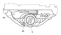
ガラス枠4の下部(窓4aの下側部分)には、遊技球を貯留する貯留皿6(上皿6aと下皿6b)を有する皿ユニット7が設けられ、その皿ユニット7に、遊技者が押下操作可能な演出ボタン8(図2)と、遊技者が種々の選択操作を実行可能な十字キー40(図2)と、下皿6bに貯留された遊技球を遊技機外部へ排出する排出ボタン9とが装備されている。
演出ボタン8は、例えば、後述する第1画像表示装置31aに当該演出ボタン8を操作するようなメッセージが表示されたときのみ有効となる。演出ボタン8には、演出ボタン検出スイッチ8a(図4参照)が設けられており、この演出ボタン検出スイッチ8aが遊技者の操作を検出すると、この操作に応じてさらなる演出が実行される。
また、十字キー40には、十字キー検出スイッチ40(上キー検出スイッチ40a、下キー検出スイッチ40b、左キー検出スイッチ40c、右キー検出スイッチ40d)(図4参照)が設けられている。
A
The
In addition, the cross key 40 is provided with a cross key detection switch 40 (an upper
ガラス枠4の右下側には、操作ハンドル11が設けられている。操作ハンドル11は、遊技者が操作ハンドル11に触れると、操作ハンドル11内にあるタッチセンサ11a(図4参照)が、操作ハンドル11に遊技者が触れたことを検知し、後述する発射制御基板160にタッチ信号を送信する。発射制御基板160は、タッチセンサ11a(図4参照)からタッチ信号を受信すると、発射用ソレノイド12aの通電を許可する。そして、操作ハンドル11の回転角度を変化させると、操作ハンドル11に直結しているギアが回転し、ギアに連結した発射ボリューム11b(図4参照)のつまみが回転する。この発射ボリューム11bの検出角度に応じた電圧が、遊技球発射機構に設けられた発射用ソレノイド12aに印加される。そして、発射用ソレノイド12a(図3参照)に電圧が印加されると、発射用ソレノイド12aが印加電圧に応じて作動するとともに、操作ハンドル11の回動角度に応じた強さで遊技球が遊技盤10の遊技領域10aへ発射される。
An operation handle 11 is provided on the lower right side of the
遊技盤10における遊技領域10aの周囲には、外レールR1及び内レールR2が設けられている。これら外レールR1及び内レールR2は、操作ハンドル11を操作したときに遊技球発射機構から発射された遊技球を遊技領域10aの上部に案内する。遊技領域10aの上部に案内された遊技球は、遊技領域10a内を落下する。このとき、遊技領域10aに設けられた複数の釘や風車によって、遊技球は予測不能に落下することとなる。
Around the
遊技盤10の略中央には、センター部材12が配置されている。センター部材12には、液晶表示装置等からなる第1画像表示装置31aと、第2画像表示装置31bと、「刀」を模した演出用役物装置32が設けられている。
A
また、センター部材12の中央下側の遊技領域10aには、遊技球が入球可能な第1始動口13が設けられている。そして、この第1始動口13の下方に第2始動口14が設けられている。第2始動口14は、開閉扉14bを有しており、開閉扉14bが閉状態に維持される第1の態様と、開閉扉14bが開状態となる第2の態様とに可動制御される。従って、第2始動口14は、第1の態様にあるときには遊技球の入賞機会がなく、第2の態様にあるときには遊技球の入賞機会が増すこととなる。
なお、本実施形態では、第2始動口14が第1の態様に制御されているときは、当該第2始動口14に遊技球が入球することがないようにしている。しかしながら、第2の態様に制御されているときよりも第1の態様に制御されているときの方が遊技球の入球機会が少なければ、第1の態様に制御されているときに第2始動口14に遊技球が入球しても構わない。つまり、第1の態様には、第2始動口14への遊技球の入球が不可能または困難な状態が含まれる。
Further, in the
In the present embodiment, when the second starting opening 14 is controlled to the first mode, the game ball is prevented from entering the second starting opening 14. However, if there is less chance of entering the gaming ball in the first mode than in the second mode, the second mode is the second mode. The game ball may enter the starting
上記第1始動口13および第2始動口14には、遊技球の入球を検出する第1始動口検出スイッチ13a(図4参照)および第2始動口検出スイッチ14aがそれぞれ設けられており、これら検出スイッチが遊技球の入球を検出すると、後述する大当たり遊技を実行する権利獲得の抽選(以下、「大当たりの抽選」という)が行われる。また、第1始動口検出スイッチ13aおよび第2始動口検出スイッチ14aが遊技球の入球を検出した場合にも、所定の賞球(例えば3個の遊技球)が払い出される。
The
なお、本実施形態の遊技機1では、第1始動口13および第2始動口14に遊技球が入球した場合、例えば3個の遊技球の払い出しを行うようにしているが、遊技球の入球に伴う払い出しは必ずしも行う必要は無い。また、例えば第1始動口13の払い出し個数を3個、第2始動口14の払い出し個数を1個といったように始動口ごとに払い出し個数を異なるように構成しても良い。
In the
センター部材12の両側の遊技領域10aには、遊技球が通過可能なゲート15が設けられている。ゲート15には、遊技球の通過を検出するゲート検出スイッチ15a(図4参照)が設けられており、このゲート検出スイッチ15aが遊技球の通過を検出すると、後述する普通図柄の抽選が行われる。
In the
さらにセンター部材12の右側の遊技領域10aには、遊技球が入球可能な第1大入賞口16および第2大入賞口17が設けられている。このため、操作ハンドル11を大きく回動させ、強い力で打ち出された遊技球でないと、第1大入賞口16および第2大入賞口17には遊技球が入賞しないように構成されている。
Furthermore, in the
第1大入賞口16は、通常は開閉扉16bによって閉状態に維持されており、遊技球の入球を不可能としている。これに対して、後述する大当たり遊技が開始されると、開閉扉16bが開放されるとともに、この開閉扉16bが遊技球を第1大入賞口16内に導く受け皿として機能し、遊技球が第1大入賞口16に入球可能となる。第1大入賞口16には第1大入賞口スイッチ16aが設けられており、この第1大入賞口スイッチ16aが遊技球の入球を検出すると、予め設定された賞球(例えば15個の遊技球)が払い出される。
The first large winning
第2大入賞口17は、通常は可動片17bによって閉状態に維持されており、遊技球の入球を不可能としている。これに対して、後述する大当たり遊技が開始されると、可動片17bが作動して開放されるとともに、この可動片17bが遊技球を第2大入賞口17内に導く誘導路として機能し、遊技球が第2大入賞口17に入球可能となる。第2大入賞口17には第2大入賞口スイッチ17aが設けられており、この第2大入賞口スイッチ17aが遊技球の入球を検出すると、予め設定された賞球(例えば15個の遊技球)が払い出される。
The second large winning
さらに、遊技領域10aには、複数の一般入賞口18が設けられている。これら各一般入賞口18に遊技球が入賞すると、所定の賞球(例えば10個の遊技球)が払い出される。
遊技領域10aの最下部には、一般入賞口18、第1始動口13、第2始動口14、第1大入賞口16および第2大入賞口17のいずれにも入球しなかった遊技球を排出するためのアウト口19が設けられている。
Furthermore, in the
In the lowermost part of the
上記第1画像表示装置31aは、遊技が行われていない待機中に画像を表示したり、遊技の進行に応じた画像を表示したりする。なかでも、第1始動口13または第2始動口14に遊技球が入球したときには、抽選結果を遊技者に報知する演出図柄35が変動表示される。
演出図柄35というのは、例えば第1図柄(左図柄)、第2図柄(右図柄)、第3図柄(中図柄)という3つの図柄(数字)をそれぞれスクロール表示するとともに、所定時間経過後に当該スクロールを停止させて、特定の図柄(数字)を配列表示するものである。
これにより、図柄のスクロール中には、あたかも現在抽選が行われているような印象を遊技者に与えるとともに、スクロールの停止時に表示される図柄によって、抽選結果が遊技者に報知される。この演出図柄35の変動表示中に、さまざまな画像やキャラクタ等を表示することによって、大当たりに当選するかもしれないという高い期待感を遊技者に与えるようにしている。
The first
The
As a result, while the symbols are being scrolled, the player is given an impression as if the lottery is currently being made, and the lottery results are informed to the player by the symbols displayed when the scrolling is stopped. By displaying various images, characters, and the like during the variable display of the
また、図示しないが、第1画像表示装置31aには、上記演出図柄35とは別に第4図柄が表示されている。第4図柄は、大当たり抽選処理による抽選結果の報知に用いる演出図柄35の変動状態を示している図柄である。
なお、第4図柄は、必ずしも第1画像表示装置31aに表示する必要は無く、別途、第4図柄表示ランプを設けて表示するようにしても良い。
Further, although not shown, a fourth symbol is displayed on the first
The fourth symbol does not necessarily have to be displayed on the first
ガラス枠4の上部には、左右1対の演出用照明装置33が装備されている。演出用照明装置33は、それぞれ複数のライトを備えており、各ライトの光の照射方向や発光色を変更しながら、さまざまな演出を行うようにしている。
At the upper part of the
また、演出用照明装置33は、それぞれ複数のライトを備えており、各ライトの光の照射方向や発光色を変更しながら、さまざまな演出を行うようにしている。
さらに、図1には示していないが、遊技機1にはスピーカからなる音声出力装置34(図4参照)が設けられており、上記の各演出装置に加えて、BGM(バックグランドミュージック)、SE(サウンドエフェクト)等を出力し、サウンドによる演出も行うようにしている。
In addition, the
Furthermore, although not shown in FIG. 1, the
遊技領域10aの左側下方には、後述する第1特別図柄表示装置20、第2特別図柄表示装置21、普通図柄表示装置22、第1特別図柄保留表示器23、第2特別図柄保留表示器24、普通図柄保留表示器25、ラウンド回数表示器26等の表示領域27が設けられている。
Below the left side of the
上記第1特別図柄表示装置20は、第1始動口13に遊技球が入球したことを契機として行われた大当たりの抽選結果を報知するものであり、複数のLEDで構成されている。つまり、大当たりの抽選結果に対応する特別図柄が複数設けられており、この第1特別図柄表示装置20に大当たりの抽選結果に対応する特別図柄(点灯態様)を表示することによって、抽選結果を遊技者に報知するようにしている。このようにして表示される特別図柄はすぐに表示されるわけではなく、所定時間変動表示(点滅)された後に、停止表示されるようにしている。
The first special
より詳細には、第1始動口13に遊技球が入球すると、大当たりの抽選が行われることとなるが、この大当たりの抽選結果は即座に遊技者に報知されるわけではなく、所定時間を経過したところで遊技者に報知される。そして、所定時間が経過したところで、大当たりの抽選結果に対応する特別図柄が停止表示して、遊技者に抽選結果が報知されるようにしている。
第2特別図柄表示装置21は、第2始動口14に遊技球が入球したことを契機として行われた大当たりの抽選結果を報知するためのもので、その表示態様は、上記第1特別図柄表示装置20における特別図柄の表示態様と同一である。
More specifically, when the game ball enters the first starting
The second special
普通図柄表示装置22は、ゲート15を遊技球が通過したことを契機として行われる普通図柄の抽選結果を報知するためのものである。詳しくは後述するが、この普通図柄の抽選によって所定の当たりに当選すると普通図柄表示装置22が点灯し、その後、上記第2始動口14が所定時間、第2の態様に制御される。なお、この普通図柄についても、ゲート15を遊技球が通過して即座に抽選結果が報知されるわけではなく、所定時間が経過するまで、普通図柄表示装置22を点滅させる等、普通図柄が変動表示するようにしている。
The normal
さらに、特別図柄の変動表示中や後述する特別遊技中等、第1始動口13または第2始動口14に遊技球が入球して、即座に大当たりの抽選が行えない場合には、一定の条件のもとで大当たりの抽選の権利が留保される。より詳細には、第1始動口13に遊技球が入球して留保される大当たりの抽選の権利は第1保留として留保され、第2始動口14に遊技球が入球して留保される大当たりの抽選の権利は第2保留として留保される。
これら両保留は、それぞれ上限留保個数を4個に設定し、その留保個数は、それぞれ第1特別図柄保留表示器23と第2特別図柄保留表示器24とに表示される。
Furthermore, when the game ball enters the first starting opening 13 or the second starting opening 14 during a special symbol variation display or during a special game to be described later, certain conditions can not be obtained if a lottery for a big hit can not be made immediately. The jackpot lottery right is reserved. More specifically, the right to draw a jackpot by which game balls enter the
In these two reservations, the upper limit reserved number is set to four, and the reserved number is displayed on the first special
そして、普通図柄の上限留保個数も4個に設定されており、その留保個数が、上記第1特別図柄保留表示器23および第2特別図柄保留表示器24と同様の態様によって、普通図柄保留表示器25において表示される。
ラウンド回数表示器26は、後述する特別遊技中に行われるラウンド遊技のラウンド回数を報知するためのものである。
And the upper limit reserved number of normal symbols is also set to four, and the reserved number is the same as the first special
The
図3に示すように、遊技機1の裏面には、主制御基板110、演出制御基板120、払出制御基板130、電源基板170、遊技情報出力端子板27などが設けられている。また、電源基板170に遊技機に電力を給電するための電源プラグ171や、図示しない電源スイッチが設けられている。
As shown in FIG. 3, on the back of the
次に、演出ボタン8について説明する。
演出ボタン8は、皿ユニット7の中央部分に組込まれている。
演出ボタン8は、図示しない通常操作位置と、通常操作位置よりも下方へ退入した押下位置と、通常操作位置よりも上方へ突出した突出操作位置とに亙って進退可能に構成されている。また、演出ボタン8は通常操作位置及び突出操作位置を含む任意の位置から押下位置へ押下操作可能に構成されている。
なお、本明細書では演出ボタン8の詳細な構造については、例えば特開2013−116168公報等に開示されているので説明を省略する。
Next, the
The
The
In addition, since the detailed structure of the
<遊技制御装置の構成>
次に、図4を用いて、本実施形態の遊技機1において遊技の進行を制御する遊技制御装置について説明する。
この図4において、主制御基板110は遊技の基本動作を制御する。この主制御基板110は、メインCPU111、メインROM112、メインRAM113から構成されるワンチップマイコン114と、主制御用の入力ポートと出力ポート(図示せず)とを少なくとも備えている。
メインCPU111は、各検出スイッチからの入力信号に基づいて、メインROM112に格納されたプログラムを読み出して演算処理を行うとともに、各装置や表示器を直接制御したり、あるいは演算処理の結果に応じて他の基板にコマンドを送信したりする。メインRAM113は、メインCPU111の演算処理時におけるデータのワークエリアとして機能する。
<Configuration of Game Control Device>
Next, with reference to FIG. 4, a game control apparatus for controlling the progress of the game in the
In FIG. 4, the
The main CPU 111 reads a program stored in the main ROM 112 based on an input signal from each detection switch to perform arithmetic processing, and directly controls each device or display, or according to the result of the arithmetic processing. Send commands to other boards. The main RAM 113 functions as a work area of data at the time of arithmetic processing of the main CPU 111.
上記主制御基板110の入力側には、第1始動口検出スイッチ13a、第2始動口検出スイッチ14a、ゲート検出スイッチ15a、第1大入賞口検出スイッチ16a、第2大入賞口検出スイッチ17a、一般入賞口検出スイッチ18aが接続されており、遊技球の検出信号を主制御基板110に入力するようにしている。
On the input side of the
また、主制御基板110の出力側には、第2始動口14の開閉扉14bを開閉動作させる始動口開閉ソレノイド14c、第1大入賞口16の開閉扉16bを開閉動作させる第1大入賞口開閉ソレノイド16c、第2大入賞口17の可動片17bを開閉動作させる第2大入賞口開閉ソレノイド17cが接続されている。
さらに、主制御基板110の出力側には、第1特別図柄表示装置20、第2特別図柄表示装置21、普通図柄表示装置22、第1特別図柄保留表示器23、第2特別図柄保留表示器24、普通図柄保留表示器25、およびラウンド回数表示器26が接続されており、出力ポートを介して各種信号を出力するようにしている。
また、主制御基板110は、遊技店のホールコンピュータ等において遊技機の管理をするために必要となる外部情報信号を遊技情報出力端子板27に出力する。
In addition, on the output side of the
Furthermore, on the output side of the
Further, the
主制御基板110のメインROM112には、後述する遊技制御用のプログラムや各種の遊技に必要なデータ、テーブルが記憶されている。
また、主制御基板110のメインRAM113は、複数の記憶領域を有している。
例えば、メインRAM113には、普通図柄保留数(G)記憶領域、普通図柄保留記憶領域、第1特別図柄保留数(U1)記憶領域、第2特別図柄保留数(U2)記憶領域、判定記憶領域、第1特別図柄記憶領域、第2特別図柄記憶領域、高確率遊技回数(X)記憶領域、時短遊技回数(J)記憶領域、ラウンド遊技回数(R)記憶領域、開放回数(K)記憶領域、第1大入賞口入球数(C1)記憶領域、第2大入賞口入球数(C2)記憶領域、遊技状態記憶領域、遊技状態バッファ、停止図柄データ記憶領域、演出用伝送データ格納領域等が設けられている。そして、遊技状態記憶領域は、時短遊技フラグ記憶領域、高確率遊技フラグ記憶領域、特図特電処理データ記憶領域、普図普電処理データ記憶領域を備えている。なお、上述した記憶領域は一例に過ぎず、この他にも多数の記憶領域が設けられている。
The main ROM 112 of the
Further, the main RAM 113 of the
For example, in the main RAM 113, a number of normal symbol holding (G) storage area, a normal symbol holding storage area, a first special symbol holding number (U1) storage area, a second special symbol holding number (U2) storage area, a determination storage area , 1st special symbol storage area, 2nd special symbol storage area, high probability game frequency (X) storage area, time saving game frequency (J) storage area, round game frequency (R) storage area, opening frequency (K) storage area , 1st winning a prize opening ball number (C1) storage area, 2nd winning a prize opening ball number (C2) storage area, gaming state storage area, gaming state buffer, stop symbol data storage area, transmission data storage area for effect Etc. are provided. The gaming state storage area is provided with a time saving game flag storage area, a high probability gaming flag storage area, a special figure special power processing data storage area, and a common view general power processing data storage area. The above-described storage area is merely an example, and many other storage areas are provided.
遊技情報出力端子板27は、主制御基板110において生成された外部情報信号を遊技店のホールコンピュータ等に出力するための基板である。遊技情報出力端子板27は、主制御基板110と配線接続されるとともに、遊技店のホールコンピュータ等に接続をするためのコネクタが設けられている。
The game information
電源基板170は、電源プラグ171から供給される電源電圧を所定電圧に変換して各制御基板に供給する。また、電源基板170はコンデンサからなるバックアップ電源を備えており、遊技機に供給する電源電圧を監視し、電源電圧が所定値以下となったときに、電断検知信号を主制御基板110に出力する。より具体的には、電断検知信号がハイレベルになるとメインCPU111は動作可能状態になり、電断検知信号がローレベルになるとメインCPU111は動作停止状態になる。バックアップ電源はコンデンサに限らず、例えば、電池でもよく、コンデンサと電池とを併用して用いてもよい。
The
演出制御基板120は、主に遊技中や待機中等の各演出を制御する。この演出制御基板120は、サブCPU121、サブROM122、サブRAM123を備えており、主制御基板110に対して、当該主制御基板110から演出制御基板120への一方向に通信可能に接続されている。
サブCPU121は、主制御基板110から送信されたコマンド、または、ランプ制御基板140を介して入力される演出ボタン検出スイッチ8aからの入力信号に基づいて、サブROM122に格納されたプログラムを読み出して演算処理を行うとともに、当該処理に基づいて、対応するデータをランプ制御基板140または画像制御基板150に送信する。サブRAM123は、サブCPU121の演算処理時におけるデータのワークエリアとして機能する。
The
The
演出制御基板120のサブROM122には、演出制御用のプログラムや各種の遊技に必要なデータ、テーブルが記憶されている。
例えば、主制御基板110から受信した変動パターン指定コマンドに基づいて演出パターンを決定するための変動演出パターン決定テーブル(図示省略)、停止表示する演出図柄35の組み合わせを決定するための演出図柄パターン決定テーブル(図示省略)等がサブROM122に記憶されている。なお、上述したテーブルは、本実施形態におけるテーブルのうち、特徴的なテーブルを一例として列挙しているに過ぎず、遊技の進行にあたっては、この他にも不図示のテーブルやプログラムが多数設けられている。
The sub ROM 122 of the
For example, a variation rendering pattern determination table (not shown) for determining a rendering pattern based on a variation pattern designation command received from the
演出制御基板120のサブRAM123は、複数の記憶領域を有している。
サブRAM123には、コマンド受信バッファ、遊技状態記憶領域、演出モード記憶領域、演出パターン記憶領域、演出図柄記憶領域、判定記憶領域(第0記憶領域)、第1保留記憶領域、第2保留記憶領域等が設けられている。なお、上述した記憶領域も一例に過ぎず、この他にも多数の記憶領域が設けられている。
The
The
また、演出制御基板120には、現在時刻を出力するRTC(リアルタイムクロック)124が搭載されている。サブCPU121は、RTC124から現在の日付を示す日付信号や現在の時刻を示す時刻信号を入力し、現在の日時に基づいて各種処理を実行する。
RTC124は、通常、遊技機に電源が供給されているときには遊技機からの電源によって動作し、遊技機の電源が切られているときには、電源基板170に搭載されたバックアップ電源から供給される電源によって動作する。したがって、RTC124は、遊技機の電源が切られている場合であっても現在の日時を計時することができる。なお、RTC124は、演出制御基板120上に電池を設けて、かかる電池によって動作するようにしてもよい。
Further, the
The
払出制御基板130は、遊技球の発射制御と賞球の払い出し制御を行う。この払出制御基板130は、払出CPU131、払出ROM132、払出RAM133を備えており、主制御基板110に対して、双方向に通信可能に接続されている。払出CPU131は、遊技球が払い出されたか否かを検知する払出球計数スイッチ135、扉開放スイッチ136からの入力信号に基づいて、払出ROM132に格納されたプログラムを読み出して演算処理を行うとともに、当該処理に基づいて、対応するデータを主制御基板110に送信する。
The
また、払出制御基板130の出力側には、遊技球の貯留部から所定数の賞球を遊技者に払い出すための賞球払出装置の払出モータ134が接続されている。払出CPU131は、主制御基板110から送信された払出個数指定コマンドに基づいて、払出ROM132から所定のプログラムを読み出して演算処理を行うとともに、賞球払出装置の払出モータ134を制御して所定の賞球を遊技者に払い出す。このとき、払出RAM133は、払出CPU131の演算処理時におけるデータのワークエリアとして機能する。
また、図示しない遊技球貸出装置(カードユニット)が払出制御基板130に接続されているか確認し、遊技球貸出装置(カードユニット)が接続されていれば、発射制御基板160に遊技球を発射させることを許可する発射制御データを送信する。
Further, on the output side of the
Also, check whether the gaming ball lending device (card unit) (not shown) is connected to the
発射制御基板160は、払出制御基板130から発射制御データを受信すると発射の許可を行う。そして、タッチセンサ11aからのタッチ信号および発射ボリューム11bからの入力信号を読み出し、発射用ソレノイド12aおよび球送りソレノイド12bを通電制御し、遊技球を発射させる。
The
発射用ソレノイド12aは、ロータリーソレノイドにより構成されている。発射用ソレノイド12aには、図示しない打出部材が直結されており、発射用ソレノイド12aが回転することで打出部材を回転させる。
ここで、発射用ソレノイド12aの回転速度は、発射制御基板160に設けられた水晶発振器の出力周期に基づく周波数から、約99.9(回/分)に設定されている。これにより、1分間における発射遊技球数は、発射ソレノイドが1回転する毎に1個発射されるため、約99.9(個/分)となる。すなわち、遊技球は約0.6秒毎に発射されることになる。
球送りソレノイド12bは、直進ソレノイドにより構成され、上皿6a(図1参照)にある遊技球を発射用ソレノイド12aに直結された打出部材に向けて1個ずつ送り出す。
The firing
Here, the rotational speed of the firing
The ball feed solenoid 12b is constituted by a straight-ahead solenoid and sends out the game balls on the
ランプ制御基板140は、上記演出制御基板120に双方向通信可能に接続されており、その入力側には演出ボタン8に設けられている演出ボタン検出スイッチ8aが接続されており、演出ボタン検出スイッチ8aから検出信号が入力された場合は、演出制御基板120に出力するようにしている。
また、ランプ制御基板140には、遊技盤10に設けられた演出用役物装置32や演出用照明装置33が接続されており、ランプ制御基板140は、演出制御基板120から送信されたデータに基づいて、演出用照明装置33を点灯制御したり、光の照射方向を変更するためのモータに対する駆動制御をしたりする。また、演出用役物装置32を動作させるソレノイドやモータ等の駆動源を通電制御する。なお、本実施形態では、演出ボタン8が突出するように構成されているので演出役物装置32は演出ボタン8を含む。
The
In addition, the
画像制御基板150は、上記演出制御基板120に双方向通信可能に接続されており、その出力側に上記第1画像表示装置31a、第2画像表示装置31bおよび音声出力装置34を接続している。
The
<画像制御基板の構成>
ここで、図4を用いて画像制御基板150の構成について説明する。
図4は、画像制御基板の構成を示したブロック図である。
画像制御基板150は、第1画像表示装置(メイン液晶)31a、第2画像表示装置(サブ液晶)31bの画像表示制御を行うためホストCPU151、ホストRAM152、ホストROM153、CGROM154、水晶発振器155、VRAM156、VDP(Video Display Processor)200と、音声制御回路300とを備えている。
<Configuration of image control board>
Here, the configuration of the
FIG. 4 is a block diagram showing the configuration of the image control board.
The
ホストCPU151は、演出制御基板120から受信した後述する演出パターン指定コマンドに基づいて、VDP200にCGROM154に記憶されている画像データをメイン液晶31a、サブ液晶31bに表示させる指示を行う。かかる指示は、VDP200の制御レジスタ201におけるデータの設定、描画制御コマンド群から構成されるディスプレイリストの出力によって行われる。
また、ホストCPU151は、VDP200からVブランク割込信号や描画終了信号を受信すると、適宜割り込み処理を行う。
The
Also, upon receiving the V blank interrupt signal and the drawing end signal from the
さらに、ホストCPU151は、音声制御回路300にも、演出制御基板120から受信した演出パターン指定コマンドに基づいて、所定の音声データを音声出力装置34に出力させる指示を行う。
ホストRAM152は、ホストCPU151に内蔵されており、ホストCPU151の演算処理時におけるデータのワークエリアとして機能し、ホストROM153から読み出されたデータを一時的に記憶するものである。
Furthermore, the
The
また、ホストROM153は、マスクROMで構成されており、ホストCPU151の制御処理のプログラム、演出図柄の図柄番号と演出図柄35の種類とを対応付けた図柄配列情報、ディスプレイリストを生成するためのディスプレイリスト生成プログラム、演出パターンのアニメーションを表示するためのアニメパターン、アニメシーン情報等が記憶されている。
このアニメパターンは、演出パターンのアニメーションを表示するにあたり参照され、その演出パターンに含まれるアニメシーン情報の組み合わせや各アニメシーン情報の表示順序等を記憶している。また、アニメシーン情報には、ウェイトフレーム(表示時間)、対象データ(スプライトの識別番号、転送元アドレス等)、パラメータ(スプライトの表示位置、転送先アドレス等)、描画方法等などの情報を記憶している。
The
The animation pattern is referred to when displaying the animation of the effect pattern, and stores combinations of animation scene information included in the effect pattern, display order of each piece of animation scene information, and the like. The animation scene information stores information such as weight frame (display time), target data (sprite identification number, transfer source address, etc.), parameters (sprite display position, transfer destination address, etc.), drawing method, etc. doing.
CGROM154は、フラッシュメモリ、EEPROM、EPROM、マスクROM等から構成され、所定範囲の画素(例えば、32×32ピクセル)における画素情報の集まりからなる画像データ(スプライト、ムービー)等を圧縮して記憶している。なお、前記画素情報は、それぞれの画素毎に色番号を指定する色番号情報と画像の透明度を示すα値とから構成されている。
さらに、CGROM154には、色番号を指定する色番号情報と実際に色を表示するための表示色情報とが対応づけられたパレットデータを圧縮せずに記憶している。
なお、CGROM154は、全ての画像データを圧縮せずとも、一部のみ圧縮している構成でもよい。また、ムービーの圧縮方式としては、MPEG4等の公知の種々の圧縮方式を用いることができる。
The
Further, the
The
水晶発振器155は、パルス信号をVDP200のクロック生成回路205に出力し、このパルス信号を分周することで、クロック生成回路205にてVDP200が制御を行うためのシステムクロック、メイン液晶31a、サブ液晶31bと同期を図るための同期信号等が生成される。
The
VRAM156は、画像データの書込みまたは読み出しが高速なSRAMで構成されている。
また、VRAM156は、ホストCPU151から出力されたディスプレイリストを一時的に記憶するディスプレイリスト記憶領域156aと、伸長回路206により伸長された画像データを記憶する展開記憶領域156bと、画像を描画または表示するためのメイン液晶用第1フレームバッファ156c、メイン液晶用第2フレームバッファ156d、サブ液晶用第1フレームバッファ156e、サブ液晶用第2フレームバッファ156fとを有している。また、VRAM156には、パレットデータも記憶される。
なお、2つのメイン液晶用フレームバッファ156c、156dは、描画の開始毎に、「描画用フレームバッファ」と「表示用フレームバッファ」とに交互に切り替わるものである。
同様に2つのサブ液晶用フレームバッファ156e、156fも、描画の開始毎に、「描画用フレームバッファ」と「表示用フレームバッファ」とに交互に切り替わる。
The
Further, the
The two main liquid
Similarly, the two sub liquid
VDP200は、いわゆる画像プロセッサであり、ホストCPU151からの指示に基づいて、いずれかのフレームバッファ(表示用フレームバッファ)から画像データを読み出し、読み出した画像データに基づいて、映像信号(RGB信号等)を生成して、画像表示装置に出力するものである。
また、VDP200は、制御レジスタ201と、CGバスI/F202と、CPUI/F203と、クロック生成回路205と、伸長回路206と、描画回路207と、表示回路208と、メモリコントローラ209とを備えている。
The
The
制御レジスタ201は、VDP200が描画や表示の制御を行うためレジスタであり、制御レジスタ201に対するデータの書き込みと読み出しで、描画の制御や表示の制御が行われる。ホストCPU151は、CPUI/F203を介して、制御レジスタ201に対するデータの書き込みと読み出しを行うことができる。
この制御レジスタ201は、VDP200が動作するために必要な基本的な設定を行うシステム制御レジスタと、データの転送に必要な設定をするデータ転送レジスタと、描画の制御をするための設定をする描画レジスタと、バスのアクセスに必要な設定をするバスインターフェースレジスタと、圧縮された画像の伸長に必要な設定をする伸長レジスタと、表示の制御をするための設定をする表示レジスタと、6種類のレジスタを備えている。
The
The
CGバスI/F202は、CGROM154との通信用のインターフェース回路であり、CGバスI/F202を介して、CGROM154からの画像データがVDP200に入力される。
また、CPUI/F203は、ホストCPU151との通信用のインターフェース回路であり、CPUI/F203を介して、ホストCPU151がVDP200にディスプレイリストを出力したり、制御レジスタにアクセスしたり、VDP200からの各種の割込信号をホストCPU151が入力したりする。
The CG bus I /
The CPU I /
データ転送回路204は、各種デバイス間のデータ転送を行う。
具体的には、ホストCPU151とVRAM156とのデータ転送、CGROM154とVRAM156とのデータ転送、VRAM156の各種記憶領域(フレームバッファも含む)の相互間のデータ転送を行う。
クロック生成回路205は、水晶発振器155よりパルス信号を入力し、VDP200の演算処理速度を決定するシステムクロックを生成する。また、同期信号生成用クロックを生成し、表示回路を介して同期信号を画像表示装置に出力する。
The
Specifically, data transfer between the
The
伸長回路206は、CGROM154に圧縮された画像データを伸長するための回路であり、伸長した画像データを展開記憶領域153bに記憶させる。
描画回路207は、描画制御コマンド群から構成されるディスプレイリストによるシーケンス制御を行う回路である。
The
The
表示回路208は、VRAM156にある「表示用フレームバッファ」に記憶された画像データ(デジタル信号)から、映像信号として画像の色データを示すRGB信号(アナログ信号)を生成し、生成した映像信号(RGB信号)をメイン液晶31a、サブ液晶31bに出力する回路である。さらに、表示回路208は、メイン液晶31a、サブ液晶31bと同期を図るための同期信号(垂直同期信号、水平同期信号等)もメイン液晶31a、サブ液晶31bに出力する。
なお、本実施形態では、映像信号として、デジタル信号をアナログ信号に変換したRGB信号をメイン液晶31a、サブ液晶31bに出力するように構成したが、デジタル信号のまま映像信号を出力してもよい。
The
In the present embodiment, as a video signal, an RGB signal obtained by converting a digital signal into an analog signal is output to the main
メモリコントローラ209は、ホストCPU151からフレームバッファ切換えの指示があると、「描画用フレームバッファ」と「表示用フレームバッファ」とを切り替える制御を行うものである。
音声制御回路300には、音声データが多数格納されている音声ROMが備えられており、音制御回路300が、演出制御基板120から送信されたコマンドに基づいて所定のプログラムを読み出すとともに、音声出力装置34における音声出力制御をする。
The memory controller 209 performs control to switch between the “drawing frame buffer” and the “display frame buffer” when instructed by the
The
次に、図6乃至図18を参照して、メインROM112に記憶されている各種テーブルの詳細について説明する。 Next, details of various tables stored in the main ROM 112 will be described with reference to FIGS. 6 to 18.
<大当たり判定テーブル>
図6(a)(b)は、特別図柄変動の停止結果を大当たりとするか否かを判定する際に参照される大当たり判定テーブルの一例を示した図であり、図6(a)は第1特別図柄表示装置において参照される大当たり判定テーブルであり、図6(b)は、第2特別図柄表示装置21において参照される大当たり判定テーブルである。なお、図6(a)と図6(b)とのテーブルでは、小当たりの当選確率が相違しているものの大当たり確率は同一である。
<Big hit judgment table>
Fig.6 (a) (b) is the figure which showed an example of the big hit determination table referred when judging the stop result of a special symbol variation as a big hit, and FIG. 1 is a jackpot determination table referred to in the special symbol display device, FIG. 6 (b) is a jackpot determination table referred to in the second special
この図6(a)(b)に示す大当たり判定テーブルは、低確率時乱数判定テーブルと高確率時乱数判定テーブルとにより構成され、遊技状態を参照し、低確率時乱数判定テーブルまたは高確率時乱数判定テーブルを選択し、選択したテーブルと抽出された特別図柄判定用乱数値とに基づいて、「大当たり」、「小当たり」、「ハズレ」の何れかを判定するものである。 The jackpot determination table shown in FIGS. 6 (a) and 6 (b) is composed of a low probability random number determination table and a high probability random number determination table, and referring to the gaming state, the low probability random number determination table or high probability The random number determination table is selected, and any one of "big hit", "small hit" and "loss" is determined based on the selected table and the extracted special symbol determination random number value.
例えば、図6(a)に示す第1特別図柄表示装置20の低確率時乱数判定テーブルによれば、「7」、「317」の2個の特別図柄判定用乱数値が大当たりと判定される。一方、高確率時乱数判定テーブルによれば「7」、「37」、「67」、「97」、「127」、「157」、「187」、「217」、「247」、「277」、「317」、「337」、「367」、「397」、「427」、「457」、「487」、「517」、「547」、「577」の20個の特別図柄判定用乱数値が大当たりと判定される。
For example, according to the low probability random number determination table of the first special
また、低確率時乱数判定テーブルを用いても高確率時乱数判定テーブルを用いても、特別図柄判定用乱数値が「50」、「100」、「150」、「200」の4個の特別図柄判定用乱数値であった場合に「小当たり」と判定される。なお、上記以外の乱数値であった場合には、「ハズレ」と判定される。
したがって、特別図柄判定用乱数値の乱数範囲が0〜598であるから、第1特別図柄表示装置20の大当たり判定テーブルにおいて、低確率時に大当たりと判定される確率は1/299.5であり、高確率時に大当たりと判定される確率は10倍となって1/29.95である。また、小当たりと判定される確率は、低確率と高確率時ともに1/149.75となる。
Also, even if the low probability random number determination table or the high probability random number determination table is used, four special symbol determination random numbers of “50”, “100”, “150” and “200” are used. If it is a random number for symbol determination, it is determined as "small hit". In addition, when it is a random value other than the above, it is determined as "loss".
Therefore, since the random number range of the special symbol determination random number value is 0 to 598, in the jackpot determination table of the first special
一方、図6(b)に示す第2特別図柄表示装置21の大当たり判定テーブルでは、低確率時および高確率時に大当たりと判定される特別図柄判定用乱数値が上記第1特別図柄表示装置20と同一であるものの、小当たりと判定される特別図柄判定用乱数値が上記第1特別図柄表示装置20における大当たり判定テーブルとは異なっている。例えば、第2特別図柄表示装置21における判定テーブルでは、特別図柄判定用乱数値が「50」の場合にのみ「小当たり」と判定される。そして、上記以外の乱数値であった場合には、「ハズレ」と判定される。
したがって、第2特別図柄表示装置21における低確率時乱数判定テーブルでは、第1特別図柄表示装置20における低確率時乱数判定テーブルと同様、低確率時に大当たりと判定される確率は1/299.5であり、高確率時に大当たりと判定される確率は10倍となって1/29.95である。一方、小当たりと判定される確率は、低確率と高確率時ともに1/599となる。
On the other hand, in the jackpot determination table of the second special
Therefore, in the low probability random number determination table in the second special
<当たり判定テーブル>
次に、図6(c)は、普通図柄変動の停止結果を当たりとするか否かを判定する際に参照される当たり判定テーブルを示した図である。
図6(c)に示す当たり判定テーブルは、非時短遊技状態時乱数判定テーブルと時短遊技状態時乱数判定テーブルとから構成され、遊技状態を参照し、非時短遊技状態時乱数判定テーブルまたは時短遊技状態時乱数判定テーブルが選択され、選択されたテーブルと抽出された当たり判定用乱数値に基づいて、「当たり」か「ハズレ」かを判定する。
<Collision judgment table>
Next, FIG. 6C is a diagram showing a hit determination table which is referred to when it is determined whether or not the stop result of the normal symbol variation is to be hit.
The hit determination table shown in FIG. 6C is composed of a non-time short game state random number determination table and a time short game state random number determination table, and referring to the game state, the non-time short game state random number determination table or the time short game A state random number determination table is selected, and it is determined whether it is a "hit" or a "loss" based on the selected table and the extracted random number for collision determination.
例えば、図6(c)に示す非時短遊技状態時乱数判定テーブルによれば、「0」〜「19」の普通図柄判定用乱数値のうち、「0」という1個の乱数値が当たりと判定される。一方、時短遊技状態時乱数判定テーブルによれば、「0」〜「19」の普通図柄判定用乱数値のうち、「0」〜「18」の19個の乱数値が当たりと判定される。なお、上記以外の乱数値であった場合には、「ハズレ」と判定される。
したがって、非時短遊技状態時に普通図柄が当たりと判定される確率は1/20であり、時短遊技状態時に普通図柄が当たりと判定される確率は19/20である。
For example, according to the random number determination table in the non-time-saving gaming state shown in FIG. 6C, one random number value of "0" is among the random symbol values of "0" to "19" for ordinary symbol determination. It is judged. On the other hand, according to the time reduction gaming state random number determination table, among the random number values for “0” to “19”, 19 random number values “0” to “18” are determined to be winnings. In addition, when it is a random value other than the above, it is determined as "loss".
Therefore, the probability that the normal symbol is determined to be a hit in the non-time-saving gaming state is 1/20, and the probability that the normal symbol is determined to be a hitting in the short-time gaming state is 19/20.
<図柄決定テーブル>
図7は、特別図柄の停止図柄を決定する図柄決定テーブルを示した図である。
図7(a)は、大当たり時に停止図柄を決定するための大当たり図柄決定テーブルであり、図7(b)は、小当たり時に停止図柄を決定するための小当たり図柄決定テーブルであり、図7(c)は、ハズレ時に停止図柄を決定するためのハズレ図柄決定テーブルである。また、より詳細には各図柄決定テーブルは特別図柄表示装置ごとに構成され、第1特別図柄表示装置用の図柄決定テーブルと第2特別図柄表示装置用の図柄決定テーブルとから構成されている。
<Symbol determination table>
FIG. 7 is a diagram showing a symbol determination table for determining a stop symbol of a special symbol.
Fig.7 (a) is a big hit symbol determination table for determining a stop symbol at the time of big hit, FIG.7 (b) is a small hitting symbol determination table for determining a stop symbol at the time of small hit, (C) is a lost symbol determination table for determining a stopped symbol when lost. In more detail, each symbol determination table is configured for each special symbol display device, and is configured of a symbol determination table for the first special symbol display device and a symbol determination table for the second special symbol display device.
図7(a)に示す大当たり図柄決定テーブルでは、大当たり図柄用乱数値を参照する。そして、第1特別図柄表示装置20において大当たりと判定された時に、大当たり図柄用乱数値が「0」〜「29」であれば、停止図柄データとして「01」(第1特別図柄1)を決定する。さらに、特別図柄の変動開始時には、決定した特別図柄の種類(停止図柄データ)に基づいて、特別図柄の情報としての演出図柄指定コマンド「E0H」「01H」を生成する。
ここで、演出図柄指定コマンドは、1コマンドが2バイトのデータで構成されており、制御コマンドの分類を識別するため1バイトのMODEと、実行される制御コマンドの内容(機能)を示す1バイトのDATAとから構成される。このことは、後述する変動パターン指定コマンド、始動入賞指定コマンドについても同様である。
In the jackpot symbol determination table shown in FIG. 7A, the jackpot symbol random number value is referred to. Then, when it is determined that the first special
Here, in the effect pattern specification command, one command is composed of 2 bytes of data, 1 byte of MODE indicating 1 byte for identifying the classification of control command, and 1 byte indicating contents (function) of control command to be executed. And DATA. The same applies to the fluctuation pattern designation command and the start winning prize designation command described later.
また、第1特別図柄表示装置20において大当たりと判定された時に、大当たり図柄用乱数値が「30」〜「39」であれば、停止図柄データとして「02」(第1特別図柄2)を決定し、特別図柄の変動開始時には、演出図柄指定コマンド「E0H」「02H」を生成する。
以下、同様に、大当たり図柄用乱数値が「40」〜「49」であれば、停止図柄データとして「03」(第1特別図柄3)を決定し、演出図柄指定コマンド「E0H」「03H」を生成し、大当たり図柄用乱数値が「50」〜「59」であれば、停止図柄データとして「04」(第1特別図柄4)を決定し、演出図柄指定コマンド「E0H」「04H」を生成し、大当たり図柄用乱数値が「60」〜「69」であれば、停止図柄データとして「05」(第1特別図柄5)を決定し、演出図柄指定コマンド「E0H」「05H」を生成し、当たり図柄用乱数値が「70」〜「99」であれば、停止図柄データとして「06」(第1特別図柄6)を決定し、演出図柄指定コマンド「E0H」「06H」を生成する。
In addition, when it is determined that the first special
Similarly, if the jackpot symbol random number value is "40" to "49", "03" (the first special symbol 3) is determined as stop symbol data, and the effect symbol designation command "E0H""03H" If the big hit symbol random number value is “50” to “59”, “04” (first special symbol 4) is determined as stop symbol data, and the effect symbol designation command “E0H” “04H” is generated. If it is generated and the jackpot symbol random number value is "60" to "69", "05" (first special symbol 5) is determined as stop symbol data, and the effect symbol designation command "E0H""05H" is generated. If the winning symbol random number value is “70” to “99”, “06” (first special symbol 6) is determined as stop symbol data, and the effect symbol designating command “E0H” “06H” is generated. .
また、第2特別図柄表示装置21において大当たりと判定された時に、大当たり図柄用乱数値が「0」〜「49」であれば、停止図柄データとして「07」(第2特別図柄1)を決定し、特別図柄の変動開始時には、演出図柄指定コマンド「E1H」「01H」を生成する。
以下、同様に、大当たり図柄用乱数値が「50」〜「59」であれば、停止図柄データとして「08」(第2特別図柄2)を決定し、特別図柄の変動開始時に演出図柄指定コマンド「E1H」「02H」を生成し、大当たり図柄用乱数値が「60」〜「69」であれば、停止図柄データとして「09」(第2特別図柄3)を決定し、演出図柄指定コマンド「E1H」「03H」を生成し、大当たり図柄用乱数値が「70」〜「99」であれば、停止図柄データとして「10」(第2特別図柄4)を決定し、演出図柄指定コマンド「E1H」「04H」を生成する。
In addition, when it is determined that the second special
Similarly, if the jackpot symbol random number value is "50" to "59", "08" (the second special symbol 2) is determined as stop symbol data, and at the start of the variation of the special symbol, the designated symbol designation command If "E1H""02H" is generated and the jackpot symbol random number value is "60" to "69", "09" (the second special symbol 3) is determined as stop symbol data, and the effect symbol designation command " If the E1H "03H" is generated and the jackpot symbol random number value is "70" to "99", "10" (the second special symbol 4) is determined as stop symbol data, and the effect symbol designation command "E1H""04H" is generated.
次に、図7(b)に示す小当たり図柄決定テーブルでは、小当たり図柄用乱数値を参照する。そして、第1特別図柄表示装置20において小当たりと判定された時に、小当たり図柄用乱数値が「0」〜「49」であれば、停止図柄データとして「11」(小当たり用特別図柄A)を決定する。そして、特別図柄の変動開始時には、決定した特別図柄の種類(停止図柄データ)に基づいて、演出図柄指定コマンド「E0H」「0AH」を生成する。また、小当たり図柄用乱数値が「50」〜「99」であれば、停止図柄データとして「12」(小当たり用特別図柄B)を決定し、特別図柄の変動開始時には、演出図柄指定コマンド「E0H」「0BH」を生成する。
Next, in the small hitting symbol determination table shown in FIG. 7 (b), the small hitting symbol random number value is referred to. And, when it is determined that the first special
また第2特別図柄表示装置21の小当たり時には、小当たり図柄用乱数値が「0」〜「49」であれば、停止図柄データとして「13」(小当たり用特別図柄A)を決定し、演出図柄指定コマンド「E1H」「0AH」を生成し、小当たり図柄用乱数値が「50」〜「99」であれば、停止図柄データとして「14」(小当たり用特別図柄B)を決定し、演出図柄指定コマンド「E1H」「0BH」を生成する。
Moreover, when the small hitting of the second special
次に、図7(c)に示すハズレ図柄決定テーブルでは、第1特別図柄表示装置20においてハズレと判定された場合、停止図柄データとして「00」(特別図柄0(ハズレ)を決定し、特別図柄の変動開始時には、演出図柄指定コマンド「E0H」「00H」を生成する。また、第2特別図柄表示装置21においてハズレと判定された場合は、停止図柄データとして「00」(特別図柄0(ハズレ)を決定し、特別図柄の変動開始時には、演出図柄指定コマンド「E1H」「00H」を生成する。
Next, in the lost symbol determination table shown in FIG. 7C, when it is determined that the first special
なお、後述するように、特別図柄の種類(停止図柄データ)によって、大当たり終了後の遊技状態(図9参照)、大当たり態様(図10参照)が決定されることから、特別図柄の種類が大当たり遊技終了後の遊技状態と大当たり態様を決定するものといえる。 In addition, since the gaming state (refer to FIG. 9) after the big hit end and the big hit mode (refer to FIG. 10) are determined by the kind of the special symbol (stop symbol data) as described later, the kind of special symbol is big hit It can be said that the game state after the game end and the jackpot mode are determined.
図8は、普通図柄変動の停止結果に基づいて普通図柄を決定する際に参照される当たり普通図柄決定テーブルを示した図であり、図8(a)は、当たり判定用乱数値の判定により当たりと判定された場合に参照される普通図柄決定テーブル、図8(b)は、当たり判定用乱数値の判定によりハズレと判定された場合に参照される普通図柄決定テーブルである。
図8(a)(b)に示す普通図柄決定テーブルでは、普通図柄用乱数値(0〜10)を参照する。
そして、普通図柄表示装置22の普通図柄用乱数値が当たり判定テーブルにおいて当たりと判定された場合は、図8(a)に示すように、普通図柄用乱数値が「0」および「1」であれば、長開放図柄を決定し、普通図柄乱数値が「2」〜「10」であれば、短開放図柄を決定する。
長開放図柄の場合は、停止図柄データとして「01」を決定し、普通図柄の変動開始時には、演出図柄指定コマンド「E8H」「01H」を生成する。また、短開放図柄と決定した場合は、停止図柄データとして「02」を決定し、普通図柄の変動開始時には、演出図柄指定コマンド「E8H」「02H」を生成する。
FIG. 8 is a view showing a normal symbol determination table referred to when determining the normal symbol based on the stop result of the normal symbol variation, and FIG. 8A shows the determination of the random number value for the hit determination. The normal symbol determination table to be referred to when it is determined to be a hit, and FIG. 8 (b) is the normal symbol determination table to be referred to when it is determined to be a loss by the determination of a random number for collision determination.
In the ordinary symbol determination table shown in FIGS. 8 (a) and 8 (b), random symbol values (0 to 10) for ordinary symbols are referred to.
Then, when the normal symbol random number value of the normal
In the case of the long open symbol, "01" is determined as the stop symbol data, and at the start of variation of the normal symbol, the effect symbol designation command "E8H""01H" is generated. Further, when the short opening symbol is determined, "02" is determined as the stop symbol data, and at the start of variation of the normal symbol, the effect symbol specifying command "E8H""02H" is generated.
一方、普通図柄表示装置22の普通図柄用乱数値が当たり判定テーブルにおいてハズレと判定された場合は、図8(b)に示すように、普通図柄用乱数値が「0」〜「10」の何れの値であってもハズレ図柄を決定する。
ハズレ図柄の場合は、停止図柄データとして「00」を決定し、普通図柄の変動開始時には、演出図柄指定コマンド「E8H」「00H」を生成する。なお、長開放図柄および短開放図柄については、後で詳しく説明する。
On the other hand, when the normal symbol random number value of the normal
In the case of the lost symbol, "00" is determined as the stop symbol data, and at the start of variation of the normal symbol, the effect symbol specification command "E8H""00H" is generated. In addition, about a long opening pattern and a short opening pattern, it demonstrates in detail later.
<大当たり終了時設定データテーブル>
図9は、大当たり終了後の遊技状態を決定するための大当たり終了時設定データテーブルである。
図9に示す大当たり終了時設定データテーブルによって、特別図柄の種類(停止図柄データ)と遊技状態バッファに記憶された大当たり当選時の遊技状態とに基づき、高確率遊技フラグの設定、高確率遊技回数(X)の設定、時短遊技フラグの設定、時短遊技回数(J)の設定が行われる。
なお、大当たり当選時の遊技状態を示す遊技状態バッファの「00H」は、時短遊技フラグと高確率遊技フラグの両方がセットされていない遊技状態情報を示し、「01H」は、時短遊技フラグはセットされていないが高確率遊技フラグはセットされている遊技状態情報を示し、「02H」は、時短遊技フラグがセットされているが高確率遊技フラグがセットされていない遊技状態情報を示し、「03H」は、時短遊技フラグと高確率遊技フラグとの両方がセットされている遊技状態情報を示すものである。
<Big hit end setting data table>
FIG. 9 is a jackpot end setting data table for determining the gaming state after the jackpot end.
Setting of high probability game flag, high probability game number of times based on the kind of special symbol (stop symbol data) and the game condition at the time of big hit winning which is stored in the game state buffer by the big hit end setting data table shown in FIG. The setting of (X), the setting of the time saving game flag, and the setting of the time saving game frequency (J) are performed.
Note that "00H" in the gaming status buffer indicating the gaming status at the time of jackpot win indicates gaming status information in which both the time saving game flag and the high probability gaming flag are not set, and "01H" indicates that the time saving game flag is set. The high probability game flag indicates gaming state information that is not set but "02H" indicates gaming state information in which the short time game flag is set but the high probability game flag is not set, "03H “” Indicates gaming state information in which both the time saving game flag and the high probability game flag are set.
本実施形態では、第1特別図柄表示装置20の停止図柄データが「01」〜「04」であった場合、すなわち第1特別図柄1〜4に当選した場合は、大当たり終了後の遊技状態を時短遊技状態で且つ高確率遊技状態(所謂、確変遊技状態)に設定する。このとき、時短遊技回数(J)および高確率遊技回数(X)にそれぞれ10000回をセットする。
In the present embodiment, when the stop symbol data of the first special
また、第1特別図柄表示装置20の停止図柄データが「05」であった場合、すなわち第1特別図柄5に当選した場合は、大当たり終了後の遊技状態を非時短遊技状態で且つ高確率遊技状態(所謂、潜伏確変遊技状態)に設定する。このとき、時短遊技回数(J)に0回をセットし、高確率遊技回数(X)に10000回をセットする。
Also, when the stop symbol data of the first special
また、第1特別図柄表示装置20の停止図柄データが「06」であった場合、すなわち第1特別図柄6に当選した場合は、大当たり終了後の遊技状態を時短遊技状態で且つ非高確率遊技状態(所謂、時短遊技状態)に設定する。このとき、時短遊技回数(J)に100回をセットし、高確率遊技回数(X)に0回をセットする。
Also, when the stop symbol data of the first special
また、第1特別図柄表示装置20の停止図柄データが「11」「12」であった場合、すなわち小当たり用特別図柄A、Bに当選した場合は、小当たり終了後の遊技状態が小当たり当選時の遊技状態と同じになるようにしている、すなわち、小当たり当選時の遊技状態を継続するようにしている。
但し、小当たり当選時の遊技状態バッファが00Hであるとき、すなわち、低確率遊技状態かつ非時短遊技状態のときには、小当たり終了後の特定遊技期間においては、特定の演出を行うために、専用の変動パターン決定テーブル(図15参照)が決定されるべく特定期間回数をセットするようにしている。
Also, when the stop symbol data of the first special
However, when the small hitting status game state buffer is 00H, that is, in the low probability gaming state and non time saving gaming state, in the specific gaming period after the small hitting end, in order to perform a specific effect, it is dedicated The number of specific periods is set so that the variation pattern determination table (see FIG. 15) is determined.
具体的には、小当たり終了後に特別図柄の変動表示が50回転行われるまでは特定遊技期間になるように、特定期間回数(T)に50回をセットしている。この特定遊技期間中(特定期間回数(T)>0のとき)には、後述するように図15に示す小当たり後の特定遊技期間用(低確率遊技状態用)の変動パターン決定テーブルが決定され、特定遊技期間以外(特定期間回数(T)=0のとき)には、図13に示す通常遊技状態(低確率遊技状態用)の変動パターン決定テーブルまたは図14に示す高確率遊技状態用の変動パターン決定テーブルが決定される。 Specifically, the specific period number (T) is set 50 times so that the specified gaming period is reached until the variable display of the special symbol is performed 50 times after the small hitting ends. During this specific game period (when the specific period number (T)> 0), the fluctuation pattern determination table for the specific game period (for the low probability gaming state) after the small hitting shown in FIG. 15 is determined as described later. , Other than the specified game period (when the number of specified periods (T) = 0), it is for the high probability game state shown in the variation pattern determination table of the normal game state (for low probability game state) shown in FIG. The variation pattern determination table of is determined.
また第2特別図柄表示装置21の停止図柄データが「07」〜「09」であった場合、すなわち第2特別図柄1〜3に当選した場合は、大当たり終了後の遊技状態を時短遊技状態で且つ高確率遊技状態(所謂、確変遊技状態)に設定する。このとき、時短遊技回数(J)および高確率遊技回数(X)にそれぞれ10000回をセットする。
If the stop symbol data of the second special
また、第2特別図柄表示装置21の停止図柄データが「10」であった場合、すなわち第2特別図柄4に当選した場合は、大当たり終了後の遊技状態を時短遊技状態で且つ非高確率遊技状態(所謂、時短遊技状態)に設定する。このとき、時短遊技回数(J)に100回をセットし、高確率遊技回数(X)に0回をセットする。
Also, when the stop symbol data of the second special
また、第2特別図柄表示装置21の停止図柄データが「13」「14」であった場合、すなわち小当たり用特別図柄A、Bに当選した場合は、小当たり終了後の遊技状態が小当たり当選時の遊技状態と同じになるようにしている、すなわち小当たり当選時の遊技状態を継続するようにしている。
但し、小当たり当選時の遊技状態バッファが00Hであるとき、すなわち、低確率遊技状態かつ非時短遊技状態のときには、上記第1特別図柄表示装置20の場合と同様、小当たり終了後に特別図柄の変動表示が50回転行われるまでは特定遊技期間になるように、特定期間回数(T)に50回をセットしている。
Also, when the stop symbol data of the second special
However, when the small hitting status game state buffer is 00H, that is, in the low probability gaming state and non time saving gaming state, as in the case of the first special
<特別電動役物作動態様決定テーブル>
図10は、大入賞口の開閉条件を決定する特別電動役物作動態様決定テーブルの一例を示した図である。
図10に示す特別電動役物作動態様決定テーブルを参照して、特別図柄の種類(停止図柄データ)に基づいて、大入賞口の作動態様、すなわちラウンド遊技回数(R)および大入賞口の開放態様を決定する大入賞口開放態様決定テーブルが決定される。なお、本実施形態では、「テーブル」のことを適宜省略して「TBL」と記載することにする。
<Special electric bill and box operation mode determination table>
FIG. 10 is a diagram showing an example of a special electric combination product operation mode determination table for determining the opening and closing conditions of the special winning opening.
With reference to the special motorized service item operation mode determination table shown in FIG. 10, based on the type of special symbol (stop symbol data), the operation mode of the special winning opening, ie, the number of round games (R) and the opening of the special winning opening A winning opening opening mode determination table for determining the mode is determined. In the present embodiment, “table” is appropriately omitted and described as “TBL”.
具体的には、停止図柄データが「01」のときは、ラウンド遊技回数Rを「16」、開放態様テーブルを後述する「長当たり1TBL」に決定する。
また、停止図柄データが「02」のときは、ラウンド遊技回数Rを「16」、開放態様テーブルを後述する「発展当たり1TBL」に決定し、停止図柄データが「03」のときは、ラウンド遊技回数Rを「16」、開放態様テーブルを後述する「発展当たり2TBL」に決定する。
また、停止図柄データが「04」「05」のときは、ラウンド遊技回数Rを「4」、開放態様テーブルを後述する「短当たりTBL」に決定し、停止図柄データが「06」のときは、ラウンド遊技回数Rを「16」、開放態様テーブルを後述する「長当たり2TBL」に決定する。
Specifically, when the stop symbol data is "01", the number of round games R is determined to be "16", and the release mode table is determined to be "1 TBL per long" described later.
Also, when the stop symbol data is "02", the number of round games R is determined to be "16", the release mode table is determined to be "1 TBL per development" described later, and when the stop symbol data is "03", the round game is The number of times R is determined to be “16”, and the release mode table is determined to be “2TBL per development” described later.
Also, when the stop symbol data is "04" and "05", the number of round games R is determined to be "4", the release mode table is determined to be "short TBL" described later, and the stop symbol data is "06". The round game frequency R is determined to be "16", and the opening mode table is determined to be "2TBL per long" described later.
さらに、停止図柄データが「07」のときは、ラウンド遊技回数Rを「16」、開放態様テーブルを「長当たり1TBL」に決定し、停止図柄データが「08」のときは、ラウンド遊技回数Rを「16」、開放態様テーブルを「発展当たり1TBL」に決定し、停止図柄データが「09」のときは、ラウンド遊技回数Rを「16」、開放態様テーブルを「発展当たり2TBL」に決定し、停止図柄データが「10」のときは、ラウンド遊技回数Rを「16」、開放態様テーブルを「長当たり1TBL」に決定する。 Furthermore, when the stop symbol data is "07", the number of round games R is determined to be "16", the open mode table is determined to be "1 TBL per long", and when the stop symbol data is "08", the number of round games R is Is determined as "16 T" for the open mode table and "1 TBL per development", and when the stop symbol data is "09", the round game frequency R is determined to "16" and the open mode table is "2 TBL per development" When the stop symbol data is "10", the number of round games R is determined to be "16", and the release mode table is determined to be "1 TBL per long".
<大入賞口開放態様決定テーブル>
図11は、図10において決定された大入賞口開放態様決定テーブルの構成を示した図であり、この図10に示す大入賞口開放態様決定テーブルによって第1大入賞口16の開閉扉16bまたは第2大入賞口17の可動片17bの開閉条件が決定される。
この図11に示す大入賞口開放態様決定テーブルは、大当たり遊技のときに参照されるテーブルであり、長当たり1TBL、長当たり2TBL、短当たりTBL、発展当たり1TBL、発展当たり2TBLにより構成されている。
そして、長当たりTBLに基づいて長当たり遊技が実行され、短当たりTBLに基づいて短当たり遊技が実行され、発展当たりTBLに基づいて発展当たり遊技が実行されることになる。
<Big winning opening opening mode decision table>
FIG. 11 is a diagram showing the configuration of the special winning opening opening mode determination table determined in FIG. 10, and the opening /
The big winning opening opening mode determination table shown in FIG. 11 is a table to be referred to in the case of a big hit game, and is composed of 1 TBL per long, 2 TBL per long, TBL per short, 1 TBL per development, 2 TBL per development .
Then, a long game is executed based on the long TBL, a short game is executed based on the short TBL, and a development game is executed based on the development TBL.
図11に示す大当たり用の大入賞口開放態様決定テーブルには、開放する大入賞口の種類(第1大入賞口16または第2大入賞口17)と、1回の大当たり遊技における最大ラウンド遊技回数(R)と、1つのラウンドにおける大入賞口への最大入賞個数を示す規定個数と、大当り遊技の開始から最初のラウンド遊技を実行するまでの開始インターバル時間と、各ラウンド遊技における大入賞口の最大開放回数(K)と、各ラウンド遊技の1回の開放に対しての大入賞口の開放時間と、各ラウンド遊技の1回の開放に対しての大入賞口の閉鎖時間と、1つのラウンド遊技の終了から次のラウンド遊技を実行するまでの大入賞口の閉鎖インターバル時間と、最後のラウンド遊技の終了から大当り遊技の終了までの終了インターバル時間とが記憶されている。
In the big hit opening opening mode decision table for the jackpot shown in FIG. 11, the type (1st big winning
ここで、図11に示す長当たり1TBLでは、第1大入賞口16の開閉扉16bを作動させて、第1大入賞口16を1ラウンドあたり最大29秒まで開放させることができる。ただし、開放時間が29秒を経過するまでに、規定個数(9個)の遊技球が第1大入賞口16に入賞すると、開閉扉16bの作動が終了して、1ラウンドの遊技が終了することになる。この場合、最大ラウンド遊技回数Rは16ラウンドに設定される。
Here, at 1 TBL per long shown in FIG. 11, the open /
また、図11に示す長当たり2TBLでは、長当たり1TBLと同様、第1大入賞口16の開閉扉16bを作動させて、第1大入賞口16を1ラウンドあたり最大29秒まで開放させることができる。そして、1ラウンドにおいて規定個数(9個)の遊技球が第1大入賞口16に入賞すると、開閉扉16bの作動が終了して、1ラウンドの遊技が終了する。この場合も、最大ラウンド遊技回数Rは16ラウンドに設定される。
但し、長当たり2TBLにおける第1大入賞口16の開放態様は、1ラウンド目から4ラウンド目までは長当たり1TBLと同じであるが、5ラウンド目以降の開放態様が長当たり1TBLとは相違している。すなわち、長当たり2TBLでは、5ラウンド目以降は、第1大入賞口16の最大開放時間を0.052秒という極めて短い時間に設定して、第1大入賞口16に遊技球が入賞し難い状態となるようにしている。
このように本実施形態では、長当たり1TBLと長当たり2TBLとを設けたことにより、大入賞口の種類および最大ラウンド遊技回数が同じでありながら遊技者が獲得できる出球数が異なる大当たり遊技を実現することができる。
In addition, at 2TBL per long shown in FIG. 11, the open /
However, the opening mode of the first large winning
As described above, in the present embodiment, by providing 1 TBL per long and 2 TBL per long, the type of big winning opening and the number of maximum round games are the same, and the jackpot game with different numbers of balls that the player can acquire It can be realized.
また、図11に示す短当たりTBLでは、第2大入賞口17の可動片17bを作動させて、第2大入賞口17を1ラウンドあたり最大0.052秒開放させる。ただし、この場合も、1ラウンドにおいて、規定個数(9個)の遊技球が第2大入賞口17に入賞した場合は、可動片17bの作動が終了して、1ラウンドの遊技が終了することになる。この場合、最大ラウンド遊技回数Rは4ラウンドに設定される。
Further, in the short hitting TBL shown in FIG. 11, the
また、図11に示す発展当たり1TBLおよび発展当たり2TBLでは、第2大入賞口17の可動片17bを作動させて、第2大入賞口17を1つのラウンドで複数回開放をさせることができる。ただし、この場合も1つのラウンドに対して規定個数(9個)の遊技球が第2大入賞口17に入賞すると、第2大入賞口17の可動片17bの作動が終了して、1つのラウンドの遊技が終了することになる。すなわち、必ずしも1つのラウンドに対して3回(K=3)開放されるとは限らないのである。
In addition, at 1 TBL per development and 2 TBL per development shown in FIG. 11, the
また、本実施形態では、発展当たり1TBLと発展当たり2TBLとは、2ラウンド目までは開放態様が共通しているが、3ラウンド目以降は開放態様が相違している。すなわち、発展当たり1TBLによれば、3ラウンド目以降は、第2大入賞口17の開放時間が0.052秒とめて短い時間に設定されており、第2大入賞口17に遊技球が入賞困難な状態となるが、発展当たり2TBLによれば、3ラウンド目、4ラウンド目は、第2大入賞口17の開放時間が1ラウンド目、2ラウンド目と同じ最大29秒に設定されているため、第2大入賞口17に遊技球が入賞容易な状態となる。
このように構成すると、所定のラウンド(2ラウンド目)までは複数の発展当たり遊技のうち、いずれの発展当たり遊技が行われているか判別困難とすることができ、発展当たり遊技という大当たり遊技中においても、よりも有利な発展当たり遊技(発展当たり2TBL)が制御されていることの期待を持たせることができる。
Moreover, in this embodiment, although 1 TBL per development and 2 TBL per development have an open aspect common to the 2nd round, the open aspect is different after the 3rd round. That is, according to 1TBL per development, the opening time of the second large winning
By configuring in this way, it can be difficult to determine which development per game is being played among a plurality of development per game until a predetermined round (the second round), and during a big hit game of development per game Even more favorable development per game (2 TBL per development) can be expected to be controlled.
なお、本実施形態では、発展当たり遊技の後半のラウンド(2ラウンド又は4ラウンド目以降)は、第2大入賞口17へ遊技球が入賞困難な状態としているが、最も有利な発展当たり遊技に関しては、遊技球が入賞困難な状態を設けなくてもよい。
また、本実施形態では、発展当たり1TBLと発展当たり2TBLとの開放時間、閉鎖時間を全く同じ時間に設定した。しかしながら、全く同じ時間に設定せずとも、複数の発展当たり遊技のいずれであるかが判別困難となる程度の時間の差異を設けても構わない。
In the present embodiment, in the second round of development per game (2 rounds or after the fourth round), the game ball is made difficult to win the second big winning
Further, in the present embodiment, the opening time and closing time of 1TBL per development and 2TBL per development are set to the same time. However, even if the same time is not set, a difference in time may be provided such that it is difficult to determine which of the plurality of games per development is.
上述したように、本実施形態においては、第1大入賞口16を長い開放時間で開放させる「長当たり遊技」と、第2大入賞口17を短い開放時間で開放させる「短当たり遊技」と、第2大入賞口17を1つのラウンドで複数の開放をさせる「発展当たり遊技」との3種類の「大当たり遊技」が設けられている。
なお、本実施形態においては、「大当たり遊技」を「特別遊技」ということにする。
As described above, in the present embodiment, the "long play game" for opening the first big winning
In the present embodiment, "big hit game" is referred to as "special game".
また、図10に示す特別電動役物作動態様決定テーブルの特徴としては、第2始動口17に遊技球が入球した場合に作動される第2特別図柄表示装置21においては、「短当たりTBL」が決定されないように構成されている。これは、非時短遊技状態においては、第2始動口17にほとんど遊技球が入球しないのに、第2始動口17に遊技球が入球した場合に短当たりが決定されてしまうと、せっかく時短遊技状態を設けても、遊技者の遊技に対する意欲を減退させてしまうおそれがあるからである。
In addition, as a feature of the special motorized service item operation mode determination table shown in FIG. 10, in the second special
なお、本実施形態では、第2特別図柄表示装置21においては、「短当たりTBL」が決定されないように構成したが、第2特別図柄表示装置21においても「短当たりTBL」を決定するように構成しても構わない。ただし、第2特別図柄表示装置21において「短当たりTBL」を決定する場合には、第1始動口14に遊技球が入球した場合に作動される第1特別図柄表示装置20と比べて、「短当たりTBL」が決定されにくく構成することが望ましい。
In the present embodiment, the second special
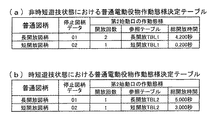
さらに本実施形態の遊技機1は、図13に示す通常遊技状態用(低確率遊技状態用)の変動パターン決定テーブルより、図14に示す確変遊技状態用(高確率遊技状態用)の変動パターン決定テーブルのほうが、遊技者に有利な大当たりに当選する割合が高くなっている、すなわち、第1特別図柄11ことから時短遊技中は通常遊技中より遊技者に有利な大当たりに当選し易い構成になっている。
Furthermore, according to the variation pattern determination table for the normal gaming state (for the low probability gaming state) shown in FIG. 13, the
図12は、図10において決定された小当たり時の大入賞口の開放態様テーブルの構成を示した図であり、この図12に示す大入賞口開放態様決定テーブルによって小当たり時の第2大入賞口17の可動片17bの開閉条件が設定される。
この図12に示す小当たり用開放態様決定テーブルが決定されると、第2大入賞口17の可動片17bが0.052秒の開放と2.000秒の閉鎖とを繰り返す小当たり遊技が実行される。この小当たり遊技は、第2大入賞口17の可動片17bが4回の開閉を連続的に繰り返す1つの遊技と捉えられるため、上記の長当たり遊技や短当たり遊技における「ラウンド遊技」という概念を用いずに制御するようにしているが、第2大入賞口17の開閉態様は実質的には短当たり遊技と同じである。これにより、遊技者に小当たりであるのか短当たりであるのかということを推測させる楽しみを付与させることができる。ただし、まったく同じ開放時間や閉鎖時間に設定しなくても、遊技者が小当たりであるのか短当たりであるのかを判別不能もしくは判別困難な程度に開閉態様を近似させれば、上記と同様に遊技の興趣を向上することができる。
FIG. 12 is a diagram showing the configuration of the opening form table of the large winning opening at the small hitting determined in FIG. 10, and the second large opening at the small hitting by the large winning opening opening determining table shown in FIG. The opening and closing conditions of the
When the small hit open mode determination table shown in FIG. 12 is determined, the small hit game in which the
なお、「短当たり」または「小当たり」の開放時間(0.052秒)は、上述したように遊技球が1個発射される時間(約0.6秒)よりも短いため、第2大入賞口17の可動片17bが開放したとしても大入賞口25に入賞することが困難であり、「短当たり」または「小当たり」の開放態様は「不利な開放態様」といえる。一方、「長当たり」の開放時間(29.5秒)は、遊技球が1個発射される時間(約0.6秒)よりも長いため、「有利な開放態様」といえる。
In addition, since the opening time (0.052 seconds) of "short hit" or "small hit" is shorter than the time when one gaming ball is fired (about 0.6 seconds) as described above, the second large Even if the
<変動パターン決定テーブル>
図13乃至図15は、特別図柄の変動パターンを決定するための変動パターン決定テーブルを示す図であり、図13は、通常遊技状態(低確率遊技状態用)に参照される通常遊技状態(低確率遊技状態用)の変動パターン決定テーブルの一例であり、図14は、高確率遊技状態時に参照される高確率遊技状態用の変動パターン決定テーブルの一例であり、図15は、小当たり終了後の特定遊技期間に参照される小当たり後の特定遊技期間用(低確率遊技状態用)の変動パターン決定テーブルの一例である。
なお、小当たり終了後の特定遊技期間は、図9に示す大当たり終了時設定データテーブルの説明で述べた通り、あくまで小当たり当選時に低確率遊技状態かつ非時短遊技状態時であるときにしか決定されないものである。
<Variation pattern determination table>
FIGS. 13 to 15 are diagrams showing a variation pattern determination table for determining the variation pattern of the special symbol, and FIG. 13 shows a normal gaming state (low) which is referred to a normal gaming state (for low probability gaming state). 14 is an example of a variation pattern determination table for probability gaming state, FIG. 14 is an example of a variation pattern determination table for high probability gaming state to be referred to in the high probability gaming state, and FIG. It is an example of a change pattern determination table for a specific gaming period (for a low probability gaming state) after a small hit which is referred to in a specific gaming period of.
In addition, as described in the description of the big hit end setting data table shown in FIG. 9, the specific game period after the small hit end is determined only when the low hit game state and the non-short play state are all at the time of the small hit. It is not possible.
具体的には、変動パターン決定テーブルによって、特別図柄表示装置の種別、特別図柄判定用乱数値(大当たりの当選または落選)、大当たり図柄用乱数値(大当たり図柄)、時短遊技状態の有無、特別図柄保留数、リーチ判定用乱数値および変動パターン用乱数値に基づき、変動パターンが決定される。
変動パターンは、特別図柄の変動開始時に決定され、決定された変動パターンに基づいて変動パターン指定コマンドが生成される。この変動パターン指定コマンドは、出力制御処理において主制御基板110から演出制御基板120へと送信される。
Specifically, according to the variation pattern determination table, the type of special symbol display device, random value for special symbol determination (win or win of big hit), random value for big hit symbol (big hit symbol), presence of time saving game state, special symbol The fluctuation pattern is determined based on the number of reservations, the random number for reach determination, and the random value for fluctuation pattern.
The variation pattern is determined at the start of variation of the special symbol, and a variation pattern specification command is generated based on the determined variation pattern. The fluctuation pattern designation command is transmitted from the
なお、本実施形態の遊技機1では、大当たりまたは小当たりのときには必ずリーチを行うように構成しているため、大当たりまたは小当たりのときにはリーチ判定用乱数値を参照しないように構成されている。
本実施形態でいう「リーチ」とは、特別遊技に移行することを報知する演出図柄35の組合せの一部が停止表示された後に、残りの一部の演出図柄35が変動表示を継続するものをいう。例えば、大当たり遊技に移行することを報知する演出図柄35の組合せとして「777」の3桁の演出図柄35の組み合わせが設定されている場合に、2つの演出図柄35が「7」で停止表示され、残りの演出図柄35が変動表示を行っている状態をいう。
In the
With "reach" in this embodiment, after a part of the combination of the
また、変動パターン指定コマンドは、MODEとして「E6H」であるときには、第1始動口13に遊技球が入球して、第1特別図柄表示装置20の特別図柄の変動開始時に決定された変動パターンに対応する変動パターン指定コマンドであることを示し、MODEとして「E7H」であるときには、第2始動口14に遊技球が入球して、第2特別図柄表示装置21の特別図柄の変動開始時に決定された変動パターンに対応する変動パターン指定コマンドであることを示す。そして、変動パターン指定コマンドのDATAは、具体的な変動パターン番号を示すものである。すなわち、変動パターン指定コマンドも変動パターンを示す情報ということになる。
In addition, when the fluctuation pattern specification command is “E6H” as MODE, the game ball enters the first starting
<通常遊技状態用の変動パターン決定テーブル>
図13に示す通常遊技状態用の変動パターン決定テーブルの構成について説明する。
変動パターン決定テーブルでは、第1特別図柄表示装置20の特別図柄の変動パターンと第2特別図柄表示装置21の特別図柄の変動パターンとが設けられているので、先ず、第1特別図柄表示装置20の特別図柄の変動パターンについて説明する。
<Variation pattern determination table for normal gaming state>
The structure of the fluctuation pattern determination table for the normal gaming state shown in FIG. 13 will be described.
In the fluctuation pattern determination table, since the fluctuation pattern of the special symbol of the first special
図13に示す通常遊技状態用の変動パターン決定テーブルでは、第1特別図柄表示装置20における特別図柄判定用乱数値が「7」または「317」で大当たりに当選したと判定され、特別図柄の種類が第1特別図柄1(特別図柄の停止図柄データ「01」)のときは、特図変動用乱数値が「0」〜「29」であれば、特別図柄の変動パターンとして変動時間が60000msの変動パターン1を選択する。そして、特別図柄の変動開始時には、特別図柄の情報として、変動パターン1に対応する変動パターン指定コマンド「E6H」「01H」を生成する。変動パターン1の変動内容は、例えばリーチAを伴う当たり演出である。
In the variation pattern determination table for the normal gaming state shown in FIG. 13, it is determined that the special symbol determination random number value in the first special
また、第1特別図柄表示装置20における特別図柄判定用乱数値が大当たりに当選したと判定され、特別図柄の種類が第1特別図柄1と判定されたときは、特図変動用乱数値が「30」〜「99」であれば、特別図柄の変動パターンとして変動時間が90000msの変動パターン2を選択する。そして、特別図柄の変動開始時には、変動パターン2に対応する変動パターン指定コマンド「E6H」「02H」を生成する。変動パターン2の変動内容は、例えばリーチBを伴う当たり演出である。
In addition, when it is determined that the special symbol determination random number value in the first special
また、第1特別図柄表示装置20における特別図柄判定用乱数値が大当たりに当選したと判定され、特別図柄の種類が第1特別図柄2、3(特別図柄の停止図柄データ「02」「03」)のときは、特図変動用乱数値「0」〜「99」に関係なく、特別図柄の変動パターンとして変動時間が75000msの変動パターン3を選択する。そして、特別図柄の変動開始時には、変動パターン3に対応する変動パターン指定コマンド「E6H」「03H」を生成する。変動パターン3の変動内容は、例えば演出図柄35が特定の図柄(例えば「7」)でリーチ状態になることを期待させる(煽る)図柄煽り演出である。
In addition, it is determined that the special symbol determination random number value in the first special
また、第1特別図柄表示装置20における特別図柄判定用乱数値が大当たりに当選したと判定され、特別図柄の種類が第1特別図柄4または第1特別図柄5(特別図柄の停止図柄データ「04」「05」)であれば、特図変動用乱数値「0」〜「99」に関係なく、特別図柄の変動パターンとして変動時間が60000msの変動パターン4または変動パターン5を選択する。そして、特別図柄の変動開始時には、変動パターン4または変動パターン5に対応した変動パターン指定コマンド「E6H」「04H」または「E6H」「05H」を生成する。変動パターン4または変動パターン5の変動内容は、例えば大当たりであることを期待させるチャンス演出である。
In addition, it is determined that the special symbol determination random number value in the first special
また、第1特別図柄表示装置20における特別図柄判定用乱数値が大当たりに当選したと判定され、特別図柄の種類が第1特別図柄6(特別図柄の停止図柄データ「06」)のときは、上記第1特別図柄1と同様、特図変動用乱数値が「0」〜「29」であれば、上述した変動パターン1を選択し、特図変動用乱数値が「30」〜「99」であれば、上述した変動パターン2を選択する。なお、変動パターン1、2の変動パターン指定コマンドおよび変動内容は上述の通りである。
In addition, when it is determined that the special symbol determination random number value in the first special
また、第1特別図柄表示装置20における特別図柄判定用乱数値が小当たりに当選したと判定されたとき、すなわち特別図柄の停止図柄データ「11」「12」のときは、特図変動用乱数値「0」〜「99」に関係なく、特別図柄の変動パターンとして変動時間が60000msの変動パターン6を選択する。そして、特別図柄の変動開始時には、変動パターン6に対応する変動パターン指定コマンド「E6H」「06H」を生成する。変動パターン6の変動内容は、例えば変動パターン4、5と同じチャンス演出である。
In addition, when it is determined that the special symbol determination random number value in the first special
次に、第1特別図柄表示装置20における特別図柄判定用乱数値が上記大当たりまたは小当たり以外のハズレの場合について説明する。
特別図柄判定用乱数値がハズレの場合は、遊技状態、第1特別図柄の保留球数、リーチ判定用乱数値、特図変動用乱数値に基づいて、特別図柄の変動パターンが決定される。
具体的には、第1特別図柄表示装置20における特別図柄判定用乱数値がハズレ(特別図柄の停止図柄データ「00」)であって、遊技状態が非時短遊技状態の場合、第1特別図柄の保留球数が「0」〜「2」であって、リーチ判定用乱数値が「0」〜「79」であれば、特図変動用乱数値「0」〜「99」に関係なく、変動時間が10000msとされる変動パターン7を選択する。そして、特別図柄の変動開始時には、変動パターン7に対応する変動パターン指定コマンド「E6H」「07H」を生成する。変動パターン7の変動内容は、例えば通常変動である。
Next, the case where the random number value for special symbol determination in the first special
When the special symbol determination random number value is a loss, the variation pattern of the special symbol is determined based on the gaming state, the number of holding balls of the first special symbol, the reach determination random number value, and the special figure variation random number value.
Specifically, when the random value for special symbol determination in the first special
一方、第1特別図柄の保留球数が「0」〜「2」であって、リーチ判定用乱数値が「80」〜「99」、特図変動用乱数値が「0」〜「69」であれば、変動時間が60000msとされる変動パターン8を選択し、特別図柄の変動開始時には、変動パターン8に対応する変動パターン指定コマンド「E6H」「08H」を生成する。変動パターン8の変動内容は、例えばリーチAを伴うハズレ演出である。
同様に、第1特別図柄の保留球数が「0」〜「2」であって、リーチ判定用乱数値が「80」〜「99」、特図変動用乱数値が「70」〜「99」であれば、変動時間が90000msとされる変動パターン9を選択し、特別図柄の変動開始時には、変動パターン9に対応する変動パターン指定コマンド「E6H」「09H」を生成する。変動パターン9の変動内容は、例えばリーチBを伴うハズレ演出である。
On the other hand, the number of holding balls of the first special symbol is "0" to "2", the reach determination random number value is "80" to "99", and the special figure variation random number value is "0" to "69" If it is, the
Similarly, the number of holding balls of the first special symbol is "0" to "2", and the random number for reach determination is "80" to "99", and the random number for special figure variation is "70" to "99". If it is “,” the
次に、第1特別図柄の保留球数が「3」であって、リーチ判定用乱数値が「0」〜「89」であれば、特図変動用乱数値「0」〜「99」に関係なく、変動パターン10を選択する。そして、特別図柄の変動開始時には、変動パターン10に対応する変動パターン指定コマンド「E6H」「0AH」を生成する。変動パターン10の変動内容は、例えば短縮変動Aである。
一方、第1特別図柄の保留球数が「3」であって、リーチ判定用乱数値が「90」〜「99」、特図変動用乱数値が「0」〜「69」であれば、上述した変動パターン8を選択し、特図変動用乱数値が「70」〜「99」であれば、上述した変動パターン9を選択する。変動パターン8、9に対応する変動パターン指定コマンドおよび変動内容は上述の通りである。
Next, if the number of holding balls in the first special symbol is "3" and the reach determination random number is "0" to "89", the special figure variation random number "0" to "99" Regardless of the
On the other hand, if the number of holding balls in the first special symbol is "3" and the reach determination random number is "90" to "99", and the special figure variation random number is "0" to "69", The above-mentioned
次に、第1特別図柄表示装置20における特別図柄判定用乱数値がハズレ(特別図柄の停止図柄データ「00」)であって、遊技状態が時短遊技状態の場合、第1特別図柄の保留球数が「0」「1」、リーチ判定用乱数値が「0」〜「84」であれば、特図変動用乱数値「0」〜「99」に関係なく、上述した変動パターン7を選択する。変動パターン7に対応する変動パターン指定コマンドおよび変動内容は上述の通りである。
一方、第1特別図柄の保留球数が「0」「1」であって、リーチ判定用乱数値が「85」〜「99」、特図変動用乱数値が「0」〜「69」であれば、上述した変動パターン8を選択し、特図変動用乱数値が「70」〜「99」であれば、上述した変動パターン9を選択する。変動パターン8、9に対応する変動パターン指定コマンドおよび変動内容は上述の通りである。
Next, when the random number for special symbol determination in the first special
On the other hand, the number of holding balls in the first special symbol is "0", "1", and the random number for reach determination is "85" to "99", and the random number for special figure variation is "0" to "69". If it exists, the above-mentioned
次に、第1特別図柄の保留球数が「2」「3」であって、リーチ判定用乱数値が「0」〜「94」であれば、特図変動用乱数値「0」〜「99」に関係なく、変動時間が3000msとされる変動パターン11を選択する。そして、特別図柄の変動開始時には、変動パターン11に対応する変動パターン指定コマンド「E6H」「0BH」を生成する。変動パターン11の変動内容は、例えば短縮変動Bである。
一方、第1特別図柄の保留球数が「3」であって、リーチ判定用乱数値が「95」〜「99」、特図変動用乱数値が「0」〜「69」であれば、上述した変動パターン8を選択し、特図変動用乱数値が「70」〜「99」であれば、上述した変動パターン9を選択する。変動パターン8、9に対応する変動パターン指定コマンドおよび変動内容は上述の通りである。
Next, if the number of holding balls of the first special symbol is "2""3" and the reach determination random number is "0" to "94", the special figure variation random number "0" to " The
On the other hand, if the number of holding balls of the first special symbol is "3" and the reach determination random number value is "95" to "99" and the special figure variation random number value is "0" to "69", The above-mentioned
次に、第2特別図柄表示装置21の特別図柄の変動パターンについて説明する。
図13に示す通常遊技状態用の変動パターン決定テーブルでは、第2特別図柄表示装置21における特別図柄判定用乱数値が「7」または「317」で大当たりに当選したと判定され、特別図柄の種類が第2特別図柄1(特別図柄の停止図柄データ「07」)のときは、特図変動用乱数値が「0」〜「29」であれば、上述した変動パターン1を選択し、特図変動用乱数値が「30」〜「99」であれば、上述した変動パターン2を選択する。なお、変動パターン1、2に対応する変動パターン指定コマンドおよび変動内容は変動パターン指定コマンドのMODEが「E7H」であること以外は、上記した第1特別図柄表示装置20の変動パターン1、2に対応する変動パターン指定コマンドおよび変動内容と同じである。
Next, the variation pattern of the special symbol of the second special
In the variation pattern determination table for the normal gaming state shown in FIG. 13, it is determined that the special symbol determination random number value in the second special
また、第2特別図柄表示装置21における特別図柄判定用乱数値が大当たりに当選したと判定され、特別図柄の種類が第2特別図柄2(特別図柄の停止図柄データ「08」)のときは、特図変動用乱数値「0」〜「99」に関係なく、上述した変動パターン3を選択する。なお、変動パターン3に対応する変動パターン指定コマンドおよび変動内容は、変動パターン指定コマンドのMODEが「E7H」であること以外は、上記した第1特別図柄表示装置20の変動パターン3に対応する変動パターン指定コマンドおよび変動内容と同じである。
In addition, when it is determined that the special symbol determination random number value in the second special
また、第2特別図柄表示装置21における特別図柄判定用乱数値が大当たりに当選したと判定され、特別図柄の種類が第2特別図柄3(特別図柄の停止図柄データ「09」)のときは、上記第2特別図柄1と同様、特図変動用乱数値が「0」〜「29」であれば、上述した変動パターン1を選択し、特図変動用乱数値が「30」〜「99」であれば、上述した変動パターン2を選択する。
In addition, when it is determined that the special symbol determination random number value in the second special
また、第2特別図柄表示装置21における特別図柄判定用乱数値が小当たりに当選したと判定されたとき、すなわち、特別図柄の停止図柄データ「13」「14」のときは、特図変動用乱数値「0」〜「99」に関係なく、上述した変動パターン6を選択する。なお、変動パターン6に対応する変動パターン指定コマンドおよび変動内容は、変動パターン指定コマンドのMODEが「E7H」であること以外は、上記した第1特別図柄表示装置20の変動パターン6の変動パターン指定コマンドおよび変動内容と同じである。
In addition, when it is determined that the special symbol determination random number value in the second special
なお、第2特別図柄表示装置21における特別図柄判定用乱数値がハズレ(特別図柄の停止図柄データ「00」)の場合は、変動パターン指定コマンドのMODEが「E7H」であること以外は、第1特別図柄表示装置20における特別図柄判定用乱数値がハズレの場合と同じであるので、説明は省略する。
In addition, when the random number for special symbol judgment in the second special
<確変遊技状態用の変動パターン決定テーブル>
次に、図14に示す確変遊技状態用の変動パターン決定テーブルの構成について説明する。
上述したように、変動パターン決定テーブルでは、第1特別図柄表示装置20の特別図柄の変動パターンと第2特別図柄表示装置21の特別図柄の変動パターンとが設けられているので、先ず、第1特別図柄表示装置20の特別図柄の変動パターンについて説明する。
<Variation pattern determination table for probability variation gaming state>
Next, the configuration of the variation pattern determination table for the probability variation gaming state shown in FIG. 14 will be described.
As described above, in the fluctuation pattern determination table, since the fluctuation pattern of the special symbol of the first special
図14に示す確変遊技状態用の変動パターン決定テーブルでは、第1特別図柄表示装置20における特別図柄判定用乱数値が「7」「37」「67」「97」「127」「157」「187」「217」「247」「277」「317」「337」「367」「397」「427」「457」「487」「517」「547」「577」で大当たりに当選したと判定され、特別図柄の種類が第1特別図柄1(停止図柄データ「01」)のときに、特図変動用乱数値が「0」〜「29」であれば、変動時間が40000msの変動パターン21を選択する。そして、特別図柄の変動開始時には、特別図柄の情報として変動パターン21に対応する変動パターン指定コマンド「E6H」「21H」を生成する。変動パターン21の変動内容は、例えばリーチCを伴う当たり演出である。
In the variation pattern determination table for the probability variation gaming state shown in FIG. 14, the special symbol determination random number value in the first special
また、第1特別図柄表示装置20における特別図柄判定用乱数値が大当たりに当選したと判定され、特別図柄の種類が第1特別図柄1(停止図柄データ「01」)のときに、特図変動用乱数値が「30」〜「99」であれば、変動時間が80000msの変動パターン22を選択する。そして、特別図柄の変動開始時には、変動パターン22に対応する変動パターン指定コマンド「E6H」「22H」を生成する。変動パターン22の変動内容は、例えばリーチDを伴う当たり演出である。
In addition, it is determined that the special symbol determination random number value in the first special
また、第1特別図柄表示装置20における特別図柄判定用乱数値が大当たりに当選したと判定され、特別図柄の種類が第1特別図柄2、3(停止図柄データ「02」「03」)であれば、特図変動用乱数値「0」〜「99」に関係なく、変動時間が75000msの変動パターン23を選択する。そして、特別図柄の変動開始時には、変動パターン23に対応する変動パターン指定コマンド「E6H」「23H」を生成する。変動パターン23の変動内容は、例えば上述した図柄煽り演出である。
In addition, it is determined that the special symbol determination random number value in the first special
また、第1特別図柄表示装置20における特別図柄判定用乱数値が大当たりに当選したと判定され、特別図柄の種類が第1特別図柄4または第1特別図柄5(停止図柄データ「04」「05」)であれば、特図変動用乱数値「0」〜「99」に関係なく、変動時間が60000msの変動パターン24または変動パターン25を選択する。そして、特別図柄の変動開始時には、変動パターン24または変動パターン25に対応する変動パターン指定コマンド「E6H」「24H」または「E6H」「25H」を生成する。変動パターン24または25の変動内容は、例えば上述したチャンス演出である。
In addition, it is determined that the special symbol determination random number value in the first special
また、第1特別図柄表示装置20における特別図柄判定用乱数値が大当たりに当選したと判定され、特別図柄の種類が第1特別図柄6(停止図柄データ「06」)のときは、上記第1特別図柄1と同様、特図変動用乱数値が「0」〜「29」であれば、上述した変動パターン21を選択し、特図変動用乱数値が「30」〜「99」であれば、上述した変動パターン22を選択する。変動パターン21、22に対応する変動パターン指定コマンドおよび変動内容は上述の通りである。
In addition, when it is determined that the special symbol determination random number value in the first special
また、第1特別図柄表示装置20における特別図柄判定用乱数値が小当たりに当選したと判定されたとき、すなわち特別図柄の停止図柄データ「11」「12」のときは、特図変動用乱数値「0」〜「99」に関係なく、変動時間が60000msの変動パターン26を選択する。そして、特別図柄の変動開始時には、変動パターン26に対応する変動パターン指定コマンド「E6H」「26H」を生成する。変動パターン26の変動内容は、例えば上述した変動パターン24、25と同じチャンス演出である。
In addition, when it is determined that the special symbol determination random number value in the first special
次に、第1特別図柄表示装置20における特別図柄判定用乱数値が上記大当たりまたは小当たり以外のハズレの場合について説明する。
特別図柄判定用乱数値がハズレの場合は、遊技状態、第1特別図柄の保留球数、リーチ判定用乱数値、特図変動用乱数値に基づいて特別図柄の変動パターンが決定される。
具体的には、第1特別図柄表示装置20における特別図柄判定用乱数値がハズレ(停止図柄データ「00」)であって、遊技状態が非時短遊技状態の場合は、第1特別図柄の保留球数、リーチ判定用乱数値、特図変動用乱数値に基づいて特別図柄の変動パターンが決定される。
具体的には、第1特別図柄の保留球数が「0」〜「2」であって、リーチ判定用乱数値が「0」〜「79」であれば、特図変動用乱数値「0」〜「99」に関係なく、変動時間が10000msとされる変動パターン27を選択する。そして、特別図柄の変動開始時には、変動パターン27に対応する変動パターン指定コマンド「E6H」「27H」を生成する。変動パターン27の変動内容は、例えば通常変動である。
Next, the case where the random number value for special symbol determination in the first special
When the special symbol determination random number value is a loss, the variation pattern of the special symbol is determined based on the gaming state, the number of holding balls of the first special symbol, the reach determination random number value, and the special figure variation random number value.
Specifically, when the random number for special symbol determination in the first special
Specifically, if the number of holding balls of the first special symbol is “0” to “2” and the reach determination random number is “0” to “79”, the special figure variation random number “0”. The
一方、第1特別図柄の保留球数が「0」〜「2」であって、リーチ判定用乱数値が「80」〜「99」、特図変動用乱数値が「0」〜「69」であれば、変動時間が60000msとされる変動パターン28を選択し、特図変動用乱数値が「70」〜「99」であれば、変動時間が90000msとされる変動パターン29を選択する。そして、特別図柄の変動開始時には、変動パターン28または変動パターン29に対応した変動パターン指定コマンド「E6H」「28H」または「E6H」「29H」を生成する。
変動パターン28の変動内容は、例えばリーチCを伴うハズレ演出、変動パターン29の変動内容は、例えばリーチDを伴うハズレ演出である。
On the other hand, the number of holding balls of the first special symbol is "0" to "2", the reach determination random number value is "80" to "99", and the special figure variation random number value is "0" to "69" In this case, the
The change content of the
次に、第1特別図柄の保留球数が「3」であって、リーチ判定用乱数値が「0」〜「89」の場合は、特図変動用乱数値「0」〜「99」に関係なく、変動時間が5000msとされる変動パターン30を選択する。そして、特別図柄の変動開始時には、変動パターン30に対応する変動パターン指定コマンド「E6H」「30H」を生成する。変動パターン30の変動内容は、例えば短縮変動Aである。
一方、第1特別図柄の保留球数が「3」であって、リーチ判定用乱数値が「90」〜「99」、特図変動用乱数値が「0」〜「69」であれば、上述した変動パターン28を選択し、特図変動用乱数値が「70」〜「99」であれば、上述した変動パターン29を選択する。変動パターン28、29に対応する変動パターン指定コマンドおよび変動内容は上述の通りである。
Next, when the number of holding balls of the first special symbol is "3" and the reach determination random number is "0" to "89", it is changed to the special figure variation random number "0" to "99". Regardless, the
On the other hand, if the number of holding balls in the first special symbol is "3" and the reach determination random number is "90" to "99", and the special figure variation random number is "0" to "69", The
次に、第1特別図柄における特別図柄判定用乱数値がハズレ(停止図柄データ「00」)であって、遊技状態が時短遊技状態の場合、第1特別図柄の保留球数が「0」「1」、リーチ判定用乱数値が「0」〜「84」であれば、特図変動用乱数値「0」〜「99」に関係なく、上述した変動パターン27を選択する。変動パターン27に対応する変動パターン指定コマンドおよび変動内容は上述の通りである。
一方、第1特別図柄の保留球数が「0」「1」であって、リーチ判定用乱数値が「85」〜「99」、特図変動用乱数値が「0」〜「69」であれば、上述した変動パターン28を選択し、特図変動用乱数値が「70」〜「99」であれば、上述した変動パターン29を選択する。変動パターン28、29に対応する変動パターン指定コマンドおよび変動内容は上述の通りである。
Next, when the random value for special symbol determination in the first special symbol is lost (stop symbol data "00") and the gaming state is the short time gaming state, the number of holding balls in the first special symbol is "0". If the random number value for reach determination is “0” to “84”, the
On the other hand, the number of holding balls in the first special symbol is "0", "1", and the random number for reach determination is "85" to "99", and the random number for special figure variation is "0" to "69". If it exists, the above-mentioned
次に、第1特別図柄の保留球数が「2」「3」であって、リーチ判定用乱数値が「0」〜「94」であれば、特図変動用乱数値「0」〜「99」に関係なく、変動時間が3000msとされる変動パターン31を選択する。そして、特別図柄の変動開始時には、変動パターン31に対応する変動パターン指定コマンド「E6H」「31H」を生成する。変動パターン31の変動内容は、例えば短縮変動Bである。
一方、第1特別図柄の保留球数が「3」であって、リーチ判定用乱数値が「95」〜「99」、特図変動用乱数値が「0」〜「69」であれば、上述した変動パターン28を選択し、特図変動用乱数値が「70」〜「99」であれば、上述した変動パターン29を選択する。変動パターン28、29に対応する変動パターン指定コマンドおよび変動内容は上述の通りである。
Next, if the number of holding balls of the first special symbol is "2""3" and the reach determination random number is "0" to "94", the special figure variation random number "0" to " Regardless of "99", the fluctuation pattern 31 in which the fluctuation time is 3000 ms is selected. Then, at the start of variation of the special symbol, the variation pattern specification command “E6H” “31H” corresponding to the variation pattern 31 is generated. The content of the fluctuation of the fluctuation pattern 31 is, for example, a shortening fluctuation B.
On the other hand, if the number of holding balls of the first special symbol is "3" and the reach determination random number value is "95" to "99" and the special figure variation random number value is "0" to "69", The
次に、第2特別図柄表示装置21の変動パターンについて説明する。
図14に示す確変遊技状態用の変動パターン決定テーブルでは、第2特別図柄表示装置21における特別図柄判定用乱数値が大当たりに当選したと判定され、特別図柄の種類が第2特別図柄1のときに、特図変動用乱数値が「0」〜「29」であれば、上述した変動パターン21を選択し、特図変動用乱数値が「30」〜「99」であれば、上述した変動パターン22を選択する。なお、変動パターン21、22に対応する変動パターン指定コマンドおよび変動内容は、変動パターン指定コマンドのMODEが「E7H」であること以外は、上記した第1特別図柄表示装置20の変動パターン21、22に対応する変動パターン指定コマンドおよび変動内容と同じである。
Next, the fluctuation pattern of the second special
In the variation pattern determination table for the probability variation gaming state shown in FIG. 14, it is determined that the special symbol determination random number value in the second special
また、第2特別図柄表示装置21における特別図柄判定用乱数値が大当たりに当選したと判定され、特別図柄の種類が第2特別図柄2(停止図柄データ「08」)であれば、特図変動用乱数値「0」〜「99」に関係なく、上述した変動パターン23を選択する。なお、変動パターン23に対応する変動パターン指定コマンドおよび変動内容は、変動パターン指定コマンドのMODEが「E7H」であること以外は、上記した第1特別図柄表示装置20の変動パターン23の変動パターン指定コマンドおよび変動内容と同じである。
また、第2特別図柄表示装置21における特別図柄判定用乱数値が大当たりに当選したと判定され、特別図柄の種類が第2特別図柄3(停止図柄データ「09」)のときは、上記第2特別図柄1と同様、特図変動用乱数値が「0」〜「29」であれば、上述した変動パターン21を選択し、特図変動用乱数値が「30」〜「99」であれば、上述した変動パターン22を選択する。
In addition, it is determined that the special symbol determination random number value in the second special
In addition, when it is determined that the special symbol determination random number value in the second special
また、第2特別図柄表示装置21における特別図柄判定用乱数値が小当たりに当選したと判定されたとき、すなわち、停止図柄データ「13」「14」のtきは、特図変動用乱数値が「0」〜「99」に関係なく、上述した変動パターン26を選択する。なお、変動パターン26に対応する変動パターン指定コマンドおよび変動内容は、変動パターン指定コマンドのMODEが「E7H」であること以外は、上記した第1特別図柄表示装置20の変動パターン26の変動パターン指定コマンドおよび変動内容と同じである。
Further, when it is determined that the special symbol determination random number value in the second special
なお、第2特別図柄表示装置21における特別図柄判定用乱数値がハズレ(停止図柄データ「00」)の場合は、変動パターン指定コマンドのMODEが「E7H」であること以外、第1特別図柄表示装置20における特別図柄判定用乱数値がハズレの場合と同じであるので説明は省略する。
In addition, when the random number for special symbol determination in the second special
<小当たり後の特定遊技期間用の変動パターン決定テーブル>
次に、図15に示す小当たり後の特定遊技期間用の変動パターン決定テーブルの構成について説明する。
先ず、第1特別図柄表示装置20の変動パターンについて説明する。
図15に示す小当たり後の特定遊技期間用の変動パターン決定テーブルでは、第1特別図柄表示装置20における特別図柄判定用乱数値が「7」「317」のときに大当たりに当選したと判定され、特別図柄の種類が第1特別図柄1のときに、特図変動用乱数値が「0」〜「29」であれば、変動時間が40000msの変動パターン21を選択する。そして、特別図柄の変動開始時には、特別図柄の情報としての変動パターン指定コマンド「E6H」「21H」を生成する。変動パターン21の変動内容は、例えばリーチCを伴う当たり演出である。
また、第1特別図柄表示装置20における特別図柄判定用乱数値が大当たりに当選したと判定され、特別図柄の種類が第1特別図柄1のときに、特図変動用乱数値が「30」〜「99」であれば、変動時間が80000msの変動パターン22を選択する。この場合には、変動パターン指定コマンド「E6H」「22H」を生成する。変動パターン22の変動内容は、例えばリーチDを伴う当たり演出である。
<Variation pattern determination table for specific game period after small hit>
Next, the configuration of the variation pattern determination table for the specific gaming period after the small hitting shown in FIG. 15 will be described.
First, the variation pattern of the first special
In the variation pattern determination table for a specific gaming period after a small hit shown in FIG. 15, it is determined that the jackpot was won when the random value for special symbol determination in the first special
In addition, when it is determined that the special symbol determination random number value in the first special
また、第1特別図柄表示装置20における特別図柄判定用乱数値が大当たりに当選したと判定され、特別図柄の種類が第1特別図柄2、3であれば、特図変動用乱数値に関わらず変動時間が60000msの変動パターン23を設定する。この場合には変動パターン指定コマンド「E6H」「23H」を生成する。変動パターン23の変動内容は、例えば演出図柄が特定の図柄でリーチ状態になることを期待させる図柄煽り演出である。
In addition, if it is determined that the special symbol determination random number value in the first special
また、第1特別図柄表示装置20における特別図柄判定用乱数値が大当たりに当選したと判定され、特別図柄の種類が第1特別図柄4または第1特別図柄5であれば、特図変動用乱数値に関係なく変動時間が60000msの変動パターン24または変動パターン25を設定し、特別図柄の変動開始時には変動パターン指定コマンド「E6H」「24H」または「E6H」「25H」を生成する。変動パターン24または25の変動内容は、例えば大当たりであることを期待させるチャンス演出である。
In addition, if it is determined that the special symbol determination random number value in the first special
また、第1特別図柄表示装置20における特別図柄判定用乱数値が大当たりに当選したと判定され、特別図柄の種類が第1特別図柄6のときは、上記第1特別図柄1と同様、特図変動用乱数値が「0」〜「29」であれば、上述した変動パターン21を設定し、特図変動用乱数値が「30」〜「99」であれば、上述した変動パターン22を設定する。変動パターン21、22の変動パターン指定コマンドおよび変動内容は上述の通りである。
In addition, when it is determined that the special symbol determination random number value in the first special
また、第1特別図柄表示装置20における特別図柄判定用乱数値が小当たりと判定されたときは、特図変動用乱数値に関係なく、変動時間が60000msの変動パターン26を設定し、特別図柄の変動開始時には変動パターン指定コマンド「E6H」「26H」を生成する。変動パターン26の変動内容は、変動パターン24、25と同じチャンス演出である。
In addition, when it is determined that the special symbol determination random number value in the first special
次に、第1特別図柄表示装置20における特別図柄判定用乱数値が上記大当たりまたは小当たり以外のハズレの場合について説明する。
特別図柄判定用乱数値がハズレの場合は、第1特別図柄の保留球数、リーチ判定用乱数値、特図変動用乱数値に基づいて特別図柄の変動パターンが決定される。
具体的には、第1特別図柄の保留球数が「0」〜「2」であって、リーチ判定用乱数値が「0」〜「79」の場合は、特図変動用乱数値「0」〜「99」に関係なく、変動時間が10000msとされる変動パターン27を設定する。そして、特別図柄の変動開始時には、変動パターン指定コマンド「E6H」「27H」を生成する。変動パターン27の変動内容は、通常変動である。
一方、第1特別図柄の保留球数が「0」〜「2」であって、リーチ判定用乱数値が「80」〜「99」、特図変動用乱数値が「0」〜「69」の場合は、変動時間が60000msとされる変動パターン28を設定し、特図変動用乱数値が「70」〜「99」の場合は、変動時間が90000msとされる変動パターン29を設定する。そして、特別図柄の変動開始時には、変動パターン指定コマンド「E6H」「28H」または「E6H」「29H」を生成する。
変動パターン28の変動内容は、リーチCを伴うハズレ演出、変動パターン29の変動内容は、リーチDを伴うハズレ演出である。
Next, the case where the random number value for special symbol determination in the first special
When the special symbol determination random number value is a loss, the variation pattern of the special symbol is determined based on the number of holding balls of the first special symbol, the reach determination random number value, and the special figure variation random number value.
Specifically, when the number of holding balls in the first special symbol is "0" to "2" and the reach determination random number is "0" to "79", the special figure variation random number "0" The
On the other hand, the number of holding balls of the first special symbol is "0" to "2", the reach determination random number value is "80" to "99", and the special figure variation random number value is "0" to "69" In this case, the
The change content of the
次に、第1特別図柄の保留球数が「3」であって、リーチ判定用乱数値が「0」〜「89」の場合は、特図変動用乱数値「0」〜「99」に関係なく、変動時間が5000msとされる変動パターン30を設定する。そして、特別図柄の変動開始時には、変動パターン指定コマンド「E6H」「30H」を生成する。変動パターン30の変動内容は、短縮変動Aである。
一方、第1特別図柄の保留球数が「3」であって、リーチ判定用乱数値が「90」〜「99」、特図変動用乱数値が「0」〜「69」の場合は、上述した変動パターン28を設定し、特図変動用乱数値が「70」〜「99」の場合は、上述した変動パターン29を設定する。変動パターン28、29の変動パターン指定コマンドおよび変動内容は上述の通りである。
Next, when the number of holding balls of the first special symbol is "3" and the reach determination random number is "0" to "89", it is changed to the special figure variation random number "0" to "99". Regardless, the
On the other hand, when the number of holding balls of the first special symbol is "3", the reach determination random number is "90" to "99", and the special figure variation random number is "0" to "69". The
次に、第2特別図柄表示装置21の変動パターンについて説明する。
図15に示す小当たり後の特定期間用の変動パターン決定テーブルでは、第2特別図柄表示装置21における特別図柄判定用乱数値が大当たりに当選したと判定され、特別図柄の種類が第2特別図柄1のときに、特図変動用乱数値が「0」〜「29」であれば、上述した変動パターン21を設定し、特図変動用乱数値が「30」〜「99」であれば、上述した変動パターン22を設定する。なお、変動パターン21、22の変動パターン指定コマンドおよび変動内容は、変動パターン指定コマンドのMODEが「E7H」であること以外は、上記した第1特別図柄表示装置20の変動パターン21、22の変動パターン指定コマンドおよび変動内容と同じである。
Next, the fluctuation pattern of the second special
In the variation pattern determination table for a specific period after a small hit shown in FIG. 15, it is determined that the special symbol determination random number value in the second special
また、第2特別図柄表示装置21における特別図柄判定用乱数値が大当たりに当選したと判定され、特別図柄の種類が第2特別図柄2であれば、特図変動用乱数値「0」〜「99」に関係なく、上述した変動パターン23を設定する。なお、変動パターン23の変動パターン指定コマンドおよび変動内容は、変動パターン指定コマンドのMODEが「E7H」であること以外は、上記した第1特別図柄表示装置20の変動パターン23の変動パターン指定コマンドおよび変動内容と同じである。
また、第2特別図柄表示装置21における特別図柄判定用乱数値が大当たりに当選したと判定され、特別図柄の種類が第2特別図柄3のときは、上記第2特別図柄1と同様、特図変動用乱数値が「0」〜「29」であれば、上述した変動パターン21を設定し、特図変動用乱数値が「30」〜「99」であれば、上述した変動パターン22を設定する。
In addition, if it is determined that the special symbol determination random number value in the second special
In addition, when it is determined that the special symbol determination random number value in the second special
また、第2特別図柄表示装置21における特別図柄判定用乱数値が小当たりと判定されたときは、特図変動用乱数値「0」〜「99」に関係なく、上述した変動パターン26を設定する。なお、変動パターン26の変動パターン指定コマンドおよび変動内容は、変動パターン指定コマンドのMODEが「E7H」であること以外は、上記した第1特別図柄表示装置20の変動パターン26の変動パターン指定コマンドおよび変動内容と同じである。
In addition, when it is determined that the special symbol determination random number value in the second special
なお、第2特別図柄表示装置21における特別図柄判定用乱数値がハズレの場合は、変動パターン指定コマンドのMODEが「E7H」であること以外は、第1特別図柄表示装置20における特別図柄判定用乱数値がハズレの場合と同じであるので説明は省略する。
In addition, when the random number for special symbol determination in the second special
上記のように、図13に示す通常遊技状態用(低確率遊技状態用)の変動パターン決定テーブルと、図14に示す高確率遊技状態用の変動パターン決定テーブルとでは、同じ乱数値等を参照したとしても、異なる変動パターンが決定されるように構成されている。したがって、変動パターンの種別によって、高確率遊技状態に決定された変動パターンか、低確率遊技状態に決定された変動パターンかを区別することができる。 As described above, in the fluctuation pattern determination table for the normal gaming state (for the low probability gaming state) shown in FIG. 13 and the fluctuation pattern determination table for the high probability gaming state shown in FIG. Even so, different variation patterns are configured to be determined. Therefore, it is possible to distinguish between the variation pattern determined to be in the high probability gaming state or the variation pattern determined to be the low probability gaming state depending on the type of variation pattern.
同様に、図13に示す通常遊技状態用(低確率遊技状態用)の変動パターン決定テーブルと、図15に示す小当たり後の特定遊技期間用(低確率遊技状態用)の変動パターン決定テーブルとでは、同じ乱数値等を参照したとしても、異なる変動パターンが決定されるように構成されている。
したがって、変動パターンの種別によって、通常遊技状態であるのか、小当たり後の特定遊技期間であるのかを区別することができる。これに対して、図14に示す高確率遊技状態用の変動パターン決定テーブルと、図15に示す小当たり後の特定遊技期間用(低確率遊技状態用)の変動パターン決定テーブルとでは、同じ変動パターンが決定可能に構成されている。したがって、変動パターンの種別によって、低確率遊技状態であるのか高確率遊技状態であるのかを区別できなくなる。
Similarly, a variation pattern determination table for a normal gaming state (for low probability gaming state) shown in FIG. 13 and a variation pattern determination table for a specific gaming period (for low probability gaming state) after a small hit shown in FIG. In this case, even if the same random value or the like is referred to, different fluctuation patterns are determined.
Therefore, depending on the type of fluctuation pattern, it is possible to distinguish whether it is a normal gaming state or a specific gaming period after a small hit. On the other hand, in the variation pattern determination table for the high probability gaming state shown in FIG. 14 and the variation pattern determination table for the specific gaming period (for low probability gaming state) after the small hitting shown in FIG. The pattern is configured to be determinable. Therefore, it becomes impossible to distinguish whether it is a low probability gaming state or a high probability gaming state depending on the type of fluctuation pattern.
さらに、図13乃至図15に示す変動パターン決定テーブルの特徴として、大当たりの判定結果がハズレの場合に遊技状態が時短遊技状態であるときには、特別図柄の変動時間が短くなるように設定されている。例えば、図13に示す変動パターン決定テーブルであれば、大当たりの判定結果がハズレの場合に保留球数が「2」または「3」のときには、時短遊技状態であればリーチ判定用乱数値に基づいて95%の確率で変動時間が3000msの変動パターン11(短縮変動B)が設定されるが、非時短遊技状態であれば変動時間が3000msを超える5000msの変動パターン10(短縮変動A)が決定される。このように、時短遊技状態になると変動時間が短くなるように設定されている。 Furthermore, as a feature of the fluctuation pattern determination table shown in FIG. 13 to FIG. 15, the fluctuation time of the special symbol is set to be short when the gaming state is the short time gaming state when the judgment result of the big hit is a loss . For example, in the case of the variation pattern determination table shown in FIG. 13, when the determination result of the big hit is a loss, when the number of holding balls is “2” or “3”, the time determination gaming state is based on the reach determination random number. The fluctuation pattern 11 (shortened fluctuation B) with a fluctuation time of 3000 ms is set with a probability of 95%, but in the non-time-short game state, the fluctuation pattern 10 (shortened fluctuation A) of 5000 ms exceeds 3000 ms. Be done. As described above, the variation time is set to be short when the time-saving gaming state is reached.
さらにまた、図13、図14に示す変動パターン決定テーブルでは、保留球数が少ないときのほうが、保留球数が多いときよりリーチになり易いように構成されている。例えば、図13に示す変動パターン決定テーブルであれば、非時短遊技状態において、第1特別図柄の大当たりの判定結果がハズレの場合にリーチが発生する確率が、保留球数が「0」〜「2」のときは20%であるのに対して、保留球数が「3」のときは10%に設定されている。 Furthermore, in the fluctuation pattern determination tables shown in FIG. 13 and FIG. 14, when the number of holding balls is small, the reach is more easily reached than when the number of holding balls is large. For example, in the variation pattern determination table shown in FIG. 13, in the non-time-saving game state, the probability that a reach will occur if the determination result of the first special symbol is a loss, the number of holding balls is “0” to “0” In contrast to 20% in the case of 2 ", it is set to 10% when the number of holding balls is" 3 ".
このように構成すると、保留球数が少ないときのほうが、リーチになり易いので、保留数が少ないときのほうが、変動時間の例えば変動パターン8、9が選択される割合が高くなる。従って、リーチ期間中に遊技者が遊技を継続して行えば、リーチ期間中に新たな保留球が発生する可能性が高くなり、特別図柄の変動が停止することにより遊技者の遊技に対する意欲が損なわれるのを防止することができる。
With this configuration, when the number of holding balls is small, the reach is more likely to be reached. Therefore, when the number of holding balls is small, for example, the ratio of selection of
<普通電動役物作動態様決定テーブル>
図16は、普通電動役物作動態様決定テーブルを示す図であり、図16(a)は、非時短遊技状態において参照されるテーブルであり、図16(b)は、時短遊技状態において参照されるテーブルである。
具体的には、ゲート15への遊技球の通過に起因して行われる普通図柄の抽選によって、長開放図柄が決定されたとき、遊技状態が非時短遊技状態であれば、長開放TBL1に基づいて始動口開閉ソレノイド14cが通電される。この長開放TBL1によれば、第2始動口14が2回開放され、その総開放時間が4.200秒に制御される。
また、非時短遊技状態において短開放図柄が決定された場合には、短開放TBL1に基づいて始動口開閉ソレノイド14cが通電される。この短開放TBL1によれば、第2始動口14が1回開放され、その総開放時間が0.200秒に制御される。
<Normal electric part and item operation mode determination table>
FIG. 16 is a diagram showing a table of determining the mode of operation of the ordinary motor-operated part, and FIG. 16 (a) is a table referred to in the non-time-short game state, and FIG. Table.
Specifically, based on the long opening TBL1, if the long opening symbol is determined by the drawing of the normal symbol caused by the passage of the gaming ball to the
Also, when the short opening symbol is determined in the non-time-short game state, the starting opening opening / closing solenoid 14c is energized based on the short opening TBL1. According to the short opening TBL1, the
一方、長開放図柄が決定されたとき、遊技状態が時短遊技状態であれば、長開放TBL2に基づいて始動口開閉ソレノイド14cが通電される。この長開放TBL2によれば、第2始動口14が1回開放され、その総開放時間が5.000秒に制御される。
また、時短遊技状態において短開放図柄が決定された場合には、短開放TBL2に基づいて始動口開閉ソレノイド14cが通電される。この短開放TBL2によれば、第2始動口14が1回開放され、その総開放時間が3.000秒に制御される。
On the other hand, when the long opening symbol is determined, if the gaming state is the short time gaming state, the starting opening opening / closing solenoid 14c is energized based on the long opening TBL2. According to the long opening TBL2, the
Further, when the short opening symbol is determined in the short time gaming state, the starting opening opening / closing solenoid 14c is energized based on the short opening TBL2. According to the short opening TBL2, the
図17は、始動口開閉ソレノイド14cの通電タイミングをテーブルごとに示すタイムチャートである。
図17(a)に示すように、長開放TBL1を参照して第2始動口14が制御される場合、第2始動口14は、まず0.2秒開放した後に4秒間の閉鎖状態を経て、再び4秒間開放される。
また、図17(b)に示すように、長開放TBL2を参照して第2始動口14が制御される場合、第2始動口14は、5.0秒間開放される。
これに対して、図17(c)に示すように、短開放TBL1を参照して第2始動口14が制御される場合、第2始動口14は、0.2秒のみ開放され、図17(d)に示すように、短開放TBL2を参照して第2始動口14が制御される場合、第2始動口14は、3.0秒開放されることとなる。
FIG. 17 is a time chart showing the energization timing of the start port opening / closing solenoid 14c for each table.
As shown in FIG. 17 (a), when the
Further, as shown in FIG. 17B, when the
On the other hand, as shown in FIG. 17 (c), when the
<特別図柄の事前判定テーブル>
図18は、大当たり抽選の結果を事前に判定するための事前判定テーブルを示す図である。
図18に示す事前判定テーブルは、特別図柄表示装置の種類(遊技球が始動口に入賞したことを検出した始動口検出スイッチの種類)、特別図柄判定用乱数値、大当たり図柄用乱数値、リーチ判定用乱数値等に基づいて、大当たり抽選の結果を事前に判定するための入賞情報が生成される。そして、生成された入賞情報に基づいて、大当たり抽選の結果を事前に判定するための始動入賞指定コマンドが生成される。
<Pre-judgment table of special symbol>
FIG. 18 is a diagram showing a prior determination table for determining in advance the result of the jackpot lottery.
The prior determination table shown in FIG. 18 includes the type of the special symbol display device (the type of start opening detection switch that detects that the game ball has won the start opening), the special symbol determination random number value, the jackpot symbol random number value, reach Based on the determination random number value and the like, winning information for determining in advance the result of the jackpot lottery is generated. Then, based on the generated winning information, a start winning designation command for determining in advance the result of the jackpot lottery is generated.
ここで、始動入賞指定コマンドは、コマンドの分類を識別するため1バイトのMODEデータと、コマンドの内容(機能)を示す1バイトのDATAデータとから構成される。本実施形態では、MODEデータとして「E8H」であるときには第1始動口13に遊技球が入賞したことに対応する始動入賞指定コマンドを示し、MODEデータとして「E9H」であるときには、第2始動口14に遊技球が入賞したことに対応する始動入賞指定コマンドを示している。
Here, the start winning combination designation command is composed of 1-byte MODE data for identifying the classification of the command, and 1-byte DATA data indicating the content (function) of the command. In the present embodiment, when “E8H” is MODE data, a start winning designation command corresponding to the game ball having won in the first starting
先ず、第1特別図柄表示装置20の事前判定テーブルについて説明する。
図18に示す特別図柄の事前判定テーブルでは、第1特別図柄表示装置20における特別図柄判定用乱数値が「7」または「317」の大当たりと判定され、特別図柄の種類が第1特別図柄1(停止図柄データが「01」)、遊技状態が非時短遊技状態のときに、特図変動用乱数値が「0」〜「29」であれば、入賞情報1を設定する。そして、第1始動口13に遊技球が入賞したときに始動入賞指定コマンド「E8H」「01H」を生成する。
First, the prior determination table of the first special
In the prior symbol determination table for the special symbol shown in FIG. 18, the random symbol value for special symbol determination in the first special
また、第1特別図柄表示装置20における特別図柄判定用乱数値が大当たりに当選したと判定され、特別図柄の種類が第1特別図柄1、遊技状態が非時短遊技状態のときに、特図変動用乱数値が「30」〜「99」であれば、入賞情報2を設定する。そして、第1始動口13に遊技球が入賞したときに始動入賞指定コマンド「E8H」「02H」を生成する。
In addition, it is determined that the special symbol determination random number value in the first special
また、第1特別図柄表示装置20における特別図柄判定用乱数値が大当たりに当選したと判定され、特別図柄の種類が第1特別図柄2、3、遊技状態が非時短遊技状態であれば、特図変動用乱数値「0」〜「99」に関係なく、入賞情報3を設定する。そして、第1始動口13に遊技球が入賞したときに始動入賞指定コマンド「E8H」「03H」を生成する。
In addition, if it is determined that the special symbol determination random number value in the first special
また、第1特別図柄表示装置20における特別図柄判定用乱数値が大当たりに当選したと判定され、特別図柄の種類が第1特別図柄4または第1特別図柄5、遊技状態が非時短遊技状態であれば、特図変動用乱数値「0」〜「99」に関係なく、入賞情報4または入賞情報5を設定し、始動入賞指定コマンド「E8H」「04H」または「E8H」「05H」を生成する。
In addition, it is determined that the special symbol determination random number value in the first special
また、第1特別図柄表示装置20における特別図柄判定用乱数値が大当たりに当選したと判定され、特別図柄の種類が第1特別図柄6、遊技状態が非時短遊技状態のときは、上記第1特別図柄1と同様、特図変動用乱数値が「0」〜「29」であれば、入賞情報1を設定し、特図変動用乱数値が「30」〜「99」であれば、入賞情報2を設定する。入賞情報1、2の始動入賞指定コマンドは上述の通りである。
In addition, when it is determined that the special symbol determination random number value in the first special
また、第1特別図柄表示装置20における特別図柄判定用乱数値が小当たりと判定され、遊技状態が非時短遊技状態のときは、特図変動用乱数値「0」〜「99」に関係なく、入賞情報6を設定し、始動入賞指定コマンド「E8H」「06H」を生成する。
Also, when the random number for special symbol determination in the first special
次に、第1特別図柄表示装置20における特別図柄判定用乱数値が上記大当たりまたは小当たり以外のハズレの場合について説明する。
特別図柄判定用乱数値がハズレであって、遊技状態が非時短遊技状態の場合は、リーチ判定用乱数値、特図変動用乱数値に基づいて入賞情報が決定される。
具体的には、リーチ判定用乱数値が「0」〜「89」の場合は、特図変動用乱数値「0」〜「99」に関係なく、入賞情報7を設定し、始動入賞指定コマンド「E8H」「07H」を生成する。
一方、リーチ判定用乱数値が「90」〜「99」、特図変動用乱数値が「0」〜「69」の場合は、入賞情報8を設定し、特図変動用乱数値が「70」〜「99」の場合は、入賞情報9を設定する。そして、第1始動口13に遊技球が入賞したときに始動入賞指定コマンド「E8H」「08H」または「E8H」「09H」を生成する。
Next, the case where the random number value for special symbol determination in the first special
When the special symbol determination random number value is a loss and the gaming state is the non-time-short game state, the winning information is determined based on the reach determination random number value and the special figure variation random number value.
Specifically, when the reach determination random number values are "0" to "89", the winning
On the other hand, when the reach determination random number value is "90" to "99" and the special figure variation random number value is "0" to "69", winning
また、時短遊技中は、第1特別図柄表示装置20における特別図柄判定用乱数値が大当たり、小当たり、ハズレに場合に関わらず、遊技状態が時短遊技状態のときは、第1始動口13に遊技球が入賞したことに対応する入賞情報の設定および始動入賞指定コマンドの生成は行わないようにしている。
In addition, during the time saving game, the random number for special symbol determination in the first special
後述するように、本実施形態の遊技機1は、第2特別図柄表示装置21に対応する図柄変動を優先するタイプの遊技機とされる。このタイプの遊技機では、時短遊技中に図柄変動が非優先である第1特別図柄表示装置20における特別図柄判定用乱数値が大当たりに当選しているか否かの事前判定の結果、その対象が大当たりであり、大当たりであることを事前判定演出により遊技者に報知した場合、図柄変動が非優先とされる第1特別図柄表示装置20に大当たりが存在することが遊技者に報知されたうえで、図柄変動が優先して行われる第2始動口に遊技球を入賞させることで、第1特別図柄表示装置20の大当たりを保留し続けた状態で、第2特別図柄表示装置21における大当たり抽選を受けることができる。この場合、遊技機の射幸性が著しく高くなってしまい適切でない。そこで、本実施形態の遊技機1では、上記したように時短遊技中は非優先側である第1始動口13に遊技球が入賞したことに対応する入賞情報の設定および始動入賞指定コマンドの生成は行わないようにしている。
As will be described later, the
次に、第2特別図柄表示装置21の事前判定テーブルについて説明する。
図18に示す特別図柄の事前判定テーブルでは、第2特別図柄表示装置21における特別図柄判定用乱数値が「7」または「317」の大当たりと判定され、特別図柄の種類が第2特別図柄1のときに、特図変動用乱数値が「0」〜「29」であれば、入賞情報11を設定し、特図変動用乱数値が「30」〜「99」であれば、入賞情報12を設定する。そして、第2始動口14に遊技球が入賞したときに始動入賞指定コマンド「E9H」「01H」または「E9H」「01H」を生成する。
Next, the prior determination table of the second special
In the prior symbol determination table for the special symbol shown in FIG. 18, the random symbol value for special symbol determination in the second special
また、第2特別図柄表示装置21における特別図柄判定用乱数値が大当たりに当選したと判定され、特別図柄の種類が第2特別図柄2であれば、特図変動用乱数値「0」〜「99」に関係なく、入賞情報13を設定する。そして、第1始動口13に遊技球が入賞したときに始動入賞指定コマンド「E9H」「03H」を生成する。
また、第2特別図柄表示装置21における特別図柄判定用乱数値が大当たりに当選したと判定され、特別図柄の種類が第2特別図柄3のときは、上記第2特別図柄1と同様、特図変動用乱数値が「0」〜「29」であれば、入賞情報11を設定し、特図変動用乱数値が「30」〜「99」であれば、入賞情報12を設定する。そして、第2始動口14に遊技球が入賞したときに始動入賞指定コマンド「E9H」「01H」または「E9H」「01H」を生成する。
In addition, if it is determined that the special symbol determination random number value in the second special
In addition, when it is determined that the special symbol determination random number value in the second special
また、第2特別図柄表示装置21における特別図柄判定用乱数値が小当たりと判定されたときは、特図変動用乱数値「0」〜「99」に関係なく、入賞情報14を設定する。そして、第2始動口14に遊技球が入賞したときに始動入賞指定コマンド「E9H」「04H」を生成する。
In addition, when it is determined that the special symbol determination random number value in the second special
次に、第2特別図柄表示装置21における特別図柄判定用乱数値が上記大当たりまたは小当たり以外のハズレの場合について説明する。
特別図柄判定用乱数値がハズレであって、遊技状態が非時短遊技状態、リーチ判定用乱数値が「0」〜「89」の場合は、特図変動用乱数値「0」〜「99」に関係なく、入賞情報15を設定し、始動入賞指定コマンド「E9H」「05H」を生成する。
一方、特別図柄判定用乱数値がハズレであって、遊技状態が非時短遊技状態、リーチ判定用乱数値が「90」〜「99」、特図変動用乱数値が「0」〜「69」の場合は、入賞情報16を設定し、特図変動用乱数値が「70」〜「99」の場合は、入賞情報17を設定する。そして、第2始動口14に遊技球が入賞したときに始動入賞指定コマンド「E9H」「06H」または「E9H」「07H」を生成する。
Next, the case where the random number for special symbol determination in the second special
If the random number for special symbol determination is lost, and the gaming state is non-short time game state, and the random number for reach determination is “0” to “89”, the special figure variation random number “0” to “99” The winning
On the other hand, the special symbol determination random number value is a loss, the gaming state is non-short time gaming state, the reach determination random number value is "90" to "99", the special figure variation random number value is "0" to "69" In the case of {circle around (1)}, the winning
また、特別図柄判定用乱数値がハズレであって、遊技状態が時短遊技状態、リーチ判定用乱数値が「0」〜「94」の場合は、特図変動用乱数値「0」〜「99」に関係なく、入賞情報15を設定し、始動入賞指定コマンド「E9H」「05H」を生成する。
また、特別図柄判定用乱数値がハズレであって、遊技状態が時短遊技状態、リーチ判定用乱数値が「90」〜「99」、特図変動用乱数値が「0」〜「69」の場合は、入賞情報16を設定し、特図変動用乱数値が「70」〜「99」の場合は、入賞情報17を設定する。そして、第2始動口14に遊技球が入賞したときに始動入賞指定コマンド「E9H」「06H」または「E9H」「07H」を生成する。
In addition, when the random number value for special symbol determination is a loss, and the gaming state is a short time gaming state, and the random number value for reach determination is “0” to “94”, the special figure variation random number values “0” to “99”. The winning
Also, the special symbol determination random number value is a loss, the gaming state is a short time gaming state, the reach determination random number value is "90" to "99", and the special figure variation random number value is "0" to "69". In the case, the winning
上述した通り、特別図柄の事前判定テーブルでは、特別図柄判定用乱数値によって「大当り」「小当たり」「ハズレ」かが判定され、大当たり図柄用乱数値によって「長当たり」、「発展当たり」、「短当たり」かの特別遊技の種類と、「高確率遊技状態に移行するか否か」が判定される。
さらに、リーチ判定用乱数値によって「リーチの発生の有無」等が判定されるので、始動入賞指定コマンドのDATAデータによって、大当たりの種別、リーチの発生の有無を特別図柄の変動開始前に判別できることとなる。例えば、入賞情報1の「E8H」「01H」の始動入賞指定コマンドであれば、第1始動口入賞、確変長当たりという情報が判別できる。なお、大当たりの場合には必ず「リーチ」を伴うことから、大当たりということでリーチが発生することも判別できる。
As described above, in the special symbol pre-judging table, whether it is "big hit", "small hit", or "loss" is determined by the random value for special symbol determination, and "long per unit", "per development", by the random value for big hit. It is determined whether the type of special game "short hit" or "whether to shift to the high probability gaming state".
Furthermore, since "the presence or absence of the occurrence of reach" is determined by the random number value for reach determination, the type of the jackpot and the presence or absence of the reach can be determined before the start of variation of the special symbol by the DATA data of the start winning designation command. It becomes. For example, in the case of the start winning designation command of “E8H” and “01H” of the winning
なお、図18に示す事前判定テーブルは、図13に示す通常遊技状態用の変動パターン決定テーブルと類似しているものである。但し、図18に示す事前判定テーブルは遊技球の始動口への入賞時に用いられるに対し、図13に示す特別図柄の変動パターン決定テーブルは特別図柄の変動開始時に用いられると点で相違している。さらに「保留球数」を参照するかしないかでも相違している。このため、図18に示す事前判定テーブルでは、大当たりやリーチの種別は判別可能であるが、[通常変動]と「短縮変動」の判別が不可能となっている。 The prior determination table shown in FIG. 18 is similar to the variation pattern determination table for the normal gaming state shown in FIG. However, while the prior determination table shown in FIG. 18 is used when winning for the starting opening of the game ball, the variation pattern determination table of the special symbol shown in FIG. 13 is different in that it is used at the start of variation of the special symbol. There is. Furthermore, it is different even if it refers to "the number of balls held" or not. For this reason, in the prior determination table shown in FIG. 18, the types of the jackpot and the reach can be determined, but it is impossible to distinguish between the “normal fluctuation” and the “shortened fluctuation”.
<遊技状態の説明>
次に、遊技が進行する際の遊技状態について説明する。
本実施形態においては、「低確率遊技状態」「高確率遊技状態」「時短遊技状態」「非時短遊技状態」のいずれかの遊技状態にて遊技が進行する。
ただし、遊技の進行中において、遊技状態が「低確率遊技状態」または「高確率遊技状態」である場合には、必ず「時短遊技状態」または「非時短遊技状態」となっている。つまり、「低確率遊技状態」であって「時短遊技状態」である場合と、「低確率遊技状態」であって「非時短遊技状態」である場合と、「高確率遊技状態」であって「時短遊技状態」である場合と、「高確率遊技状態」であって「非時短遊技状態」である場合とが存在することとなる。
さらに、「低確率遊技状態」であって「非時短遊技状態」である場合には、小当たり終了後の特定遊技期間であるときと、小当たり終了後の特定遊技期間でないときが存在する。この「低確率遊技状態」であって「非時短遊技状態」である場合に、小当たり終了後の特定遊技期間でないときを「通常遊技状態」と称することとする。
<Description of gaming state>
Next, the gaming state when the game proceeds will be described.
In the present embodiment, the game proceeds in any one of the "low probability gaming state", "high probability gaming state", "time saving gaming state" and "non time saving gaming state".
However, while the game is in progress, if the gaming state is "low probability gaming state" or "high probability gaming state", it is always "time saving gaming state" or "non time saving gaming state". That is, it is a "low probability gaming state" and a "time saving gaming state", a "low probability gaming state" and a "non time saving gaming state", and a "high probability gaming state", There will be cases of "time saving gaming state" and cases of "high probability gaming state" and "non time saving gaming state".
Furthermore, in the case of the "low probability gaming state" and the "non-short time gaming state", there are times when it is a specific gaming period after the small hitting ends and when it is not a specific playing period after the small hitting ends. In the case of the "low probability gaming state" and the "non-short time gaming state", the time when it is not the specific gaming period after the small hitting end will be referred to as the "normal gaming state".
本実施形態において「低確率遊技状態」というのは、第1始動口13または第2始動口14に遊技球が入球したことを条件として行われる大当たりの抽選において、大当たりの当選確率が1/299.5に設定された遊技状態をいう。ここでいう大当たりの当選とは、後述する「長当たり遊技」または「短当たり遊技」を実行する権利を獲得することである。 In the present embodiment, the “low probability gaming state” means that the jackpot probability is 1/1 in the jackpot lottery performed on the condition that the game ball has entered the first starting opening 13 or the second starting opening 14. The game state set to 299.5. Here, the jackpot winning is to obtain the right to execute the "long game" or the "short game" described later.
これに対して「高確率遊技状態」というのは、上記大当たりの当選確率が1/29.95に設定された遊技状態をいう。したがって、「高確率遊技状態」では、「低確率遊技状態」よりも、「長当たり遊技」または「短当たり遊技」を実行する権利の獲得が容易となる。 On the other hand, "high probability game state" means a game state in which the jackpot probability of the jackpot is set to 1 / 29.95. Therefore, in the "high probability gaming state", it is easier to obtain the right to execute the "long playing game" or the "short hitting gaming" than the "low probability gaming state".
本実施形態において「非時短遊技状態」というのは、ゲート15を遊技球が通過したことを条件として行われる普通図柄の抽選において、その抽選に要する時間が10秒に設定され、かつ、長開放図柄が決定された際の第2始動口14の総開放時間が4.2秒、短開放図柄が決定された際の第2始動口14の総開放時間が0.2秒に設定された遊技状態をいう。
これに対して「時短遊技状態」というのは、ゲート15を遊技球が通過したことを条件として行われる普通図柄の抽選において、その抽選に要する時間が1秒に設定され、かつ、長開放図柄が決定された際の第2始動口14の総開放時間が5秒、短開放図柄が決定された際の第2始動口14の総開放時間が3秒に設定された遊技状態をいう。
In the present embodiment, "non-time-saving gaming state" means that the time required for the lottery is set to 10 seconds in the lottery of the normal symbol performed on the condition that the game ball has passed through the
On the other hand, "time saving game state" means that the time required for the lottery is set to one second in the regular symbol lottery performed on condition that the game ball passes through the
また、「時短遊技状態」においては、「非時短遊技状態」よりも普通図柄の抽選で当たりに当選する確率が高くなる。したがって、「時短遊技状態」においては、「非時短遊技状態」よりも、ゲート15を遊技球が通過する限りにおいて、第2始動口14が第2の態様に制御されやすくなる。これにより、「時短遊技状態」では、遊技者が遊技球を消費せずに遊技を進行することが可能となり、非時短遊技状態のときと比べて遊技効率を大幅に高めることができる。
Further, in the "time saving gaming state", the probability of winning a hit in the lottery of the normal symbol is higher than in the "non-time saving gaming state". Therefore, in the "time saving gaming state", the second starting opening 14 is more easily controlled to the second mode as long as the gaming ball passes the
さらに本実施形態の遊技機1は、第2始動口14に遊技球が入球したときのほうが、第1始動口13に遊技球が入球したときより遊技者に有利な大当たりに当選する割合が高くなっていることから時短遊技中は通常遊技中より遊技者に有利な大当たりに当選し易い構成になっている。
なお、普通図柄の抽選において当たりに当選する確率を「非時短遊技状態」および「時短遊技状態」のいずれの遊技状態であっても変わらないように設定してもよい。
Furthermore, in the
In addition, the probability of winning a winning in the lottery of the normal symbol may be set so as not to change in any of the "non-time saving gaming state" and the "time saving gaming state".
本実施形態において「小当たり終了後の特定遊技期間」とは、高確率遊技状態であることの期待を持たせるために、高確率遊技状態と同様の演出を決定可能な変動パターン決定テーブル(図15参照)が参照される遊技期間をいう。 In the present embodiment, the “specific game period after the end of the small hit” is a variation pattern determination table (see FIG. 5) which can determine the same effect as the high probability gaming state in order to have an expectation of being in the high probability gaming state. 15) refers to the game period to which reference is made.
次に、遊技機1における遊技の進行について、フローチャートを用いて説明する。
<主制御基板のメイン処理>
図19は、主制御基板によるメイン処理を説明するフローチャートである。
電源基板170により電源が供給されると、メインCPU111にシステムリセットが発生し、メインCPU111は、以下のメイン処理を行う。
まず、ステップS10において、メインCPU111は初期化処理を行う。この処理において、メインCPU111は、メインROM112から起動プログラムを読み込むとともに、メインRAM113に記憶されるフラグなどを初期化する処理を行う。
Next, the progress of the game in the
<Main processing of main control board>
FIG. 19 is a flowchart illustrating main processing by the main control board.
When power is supplied from the
First, in step S10, the main CPU 111 performs initialization processing. In this process, the main CPU 111 reads an activation program from the main ROM 112 and initializes a flag and the like stored in the main RAM 113.
ステップS20において、メインCPU111は、変動パターン用乱数値、リーチ判定用乱数値の更新を行う遊技用乱数更新処理を行う。
ステップS30において、メインCPU111は、特別図柄判定用初期値乱数、大当たり図柄用初期値乱数、小当たり図柄用初期値乱数の更新を行う。
それ以降は、所定の割込み処理が行われるまで、メインCPU111はステップS20とステップS30の処理を繰り返し行う。
(主制御基板のタイマ割込処理)
In step S20, the main CPU 111 performs game random number updating processing for updating the variation pattern random number value and the reach determination random number value.
In step S30, the main CPU 111 updates the special symbol determination initial value random number, the big hit symbol initial value random number, and the small hit symbol initial value random number.
After that, the main CPU 111 repeatedly performs the processing of step S20 and step S30 until predetermined interrupt processing is performed.
(Timer interrupt processing of main control board)
<主制御基板のタイマ割込処理>
図20は、主制御基板によるタイマ割込処理を説明するフローチャートである。
主制御基板110に設けられたリセット用クロックパルス発生回路によって、所定の周期(4ミリ秒、以下「4ms」という)毎にクロックパルスが発生されることで、以下に説明するタイマ割込処理が実行される。
まず、ステップS101において、メインCPU111は、そのレジスタに格納されている情報をスタック領域に退避させる。
次にステップS102において、メインCPU111は、特別図柄時間カウンタの更新処理、特別電動役物の開放時間などの特別遊技タイマカウンタの更新処理、普通図柄時間カウンタの更新処理、普電開放時間カウンタの更新処理等の各種タイマカウンタを更新する時間制御処理を行う。
具体的には、メインCPU111は、特別図柄時間カウンタ、特別遊技タイマカウンタ、普通図柄時間カウンタ、普電開放時間カウンタから1を減算する処理を行う。
<Timer interrupt processing of main control board>
FIG. 20 is a flowchart illustrating timer interrupt processing by the main control board.
The clock pulse generation circuit provided on the
First, in step S101, the main CPU 111 saves the information stored in the register in the stack area.
Next, in step S102, the main CPU 111 updates the special symbol time counter, updates the special gaming timer counter such as the opening time of the special electric role, updates the normal symbol time counter, updates the general public open time counter It performs time control processing to update various timer counters such as processing.
Specifically, the main CPU 111 performs processing of subtracting 1 from the special symbol time counter, the special game timer counter, the normal symbol time counter, and the general charge open time counter.
ステップS103において、メインCPU111は、特別図柄判定用乱数値、大当たり図柄用乱数値、小当たり図柄用乱数値、当たり判定用乱数値の乱数更新処理を行う。
具体的には、それぞれの乱数カウンタに1を加算して、乱数カウンタを更新する。なお、加算した結果が乱数範囲の最大値を超えた場合には、乱数カウンタを0に戻し、乱数カウンタが1周した場合には、その時の初期値乱数の値から乱数を更新する。
ステップS104において、メインCPU111は、特別図柄判定用初期値乱数カウンタ、大当たり図柄用初期値乱数カウンタ、小当たり図柄用初期値乱数カウンタを1加算して乱数カウンタを更新する初期値乱数更新処理を行う。
In step S103, the main CPU 111 performs random number update processing of the special symbol determination random number value, the large hit symbol random number value, the small hit symbol random number value, and the hit determination random number value.
Specifically, 1 is added to each random number counter to update the random number counter. When the result of the addition exceeds the maximum value of the random number range, the random number counter is returned to 0, and when the random number counter makes one revolution, the random number is updated from the value of the initial value random number at that time.
In step S104, the main CPU 111 performs an initial value random number updating process of updating the random number counter by adding 1 to the special symbol determination initial value random number counter, the big hit symbol initial value random number counter, and the small hit symbol initial value random number counter. .
ステップS105において、メインCPU111は、入力制御処理を行う。
この処理においてメインCPU111は、第1始動口検出スイッチ13a、第2始動口検出スイッチ14a、ゲート検出スイッチ15a、第1大入賞口検出スイッチ16a、第2大入賞口検出スイッチ17a、一般入賞口検出スイッチ18aの各スイッチに入力があったか否か判定する入力処理を行う。具体的には、図21乃至図24を用いて後述する。
ステップS106において、メインCPU111は、特別図柄、特別電動役物の制御を行うための特図特電制御処理を行う。詳しくは、図25乃至図32を用いて後述する。
ステップS107において、メインCPU111は、普通図柄、普通電動役物の制御を行うための普図普電制御処理を行う。詳しくは、図33乃至図35を用いて後述する。
In step S105, the main CPU 111 performs input control processing.
In this process, the main CPU 111 detects the first start opening
At step S106, the main CPU 111 carries out a special figure special power control process for controlling the special symbol and the special motorized role. Details will be described later with reference to FIGS. 25 to 32.
At step S107, the main CPU 111 carries out a general-purpose power control control process for controlling the ordinary symbol and the ordinary motorized part. Details will be described later with reference to FIGS. 33 to 35.
ステップS108において、メインCPU111は、払出制御処理を行う。
この払出制御処理において、メインCPU111は、第1大入賞口16、第2大入賞口17、第1始動口13、第2始動口14、一般入賞口18に遊技球が入賞したか否かのチェックを行い、入賞があった場合、それぞれに対応する払出個数指定コマンドを払出制御基板130に送信する。
より具体的には、一般入賞口賞球カウンタ、大入賞口賞球カウンタ、始動口賞球カウンタ(例えば、後述する図21(ステップS132)において更新されている第1始動口賞球カウンタ)をチェックし、それぞれの入賞口に対応する払出個数指定コマンドを払出制御基板130に送信する。その後、送信した払出個数指定コマンドに対応する賞球カウンタから所定のデータを減算して更新する。
ステップS109において、メインCPU111は、外部情報データ、始動口開閉ソレノイドデータ、大入賞口開閉ソレノイドデータ、特別図柄表示装置データ、普通図柄表示装置データ、記憶数指定コマンドのデータ作成処理を行う。
In step S108, the main CPU 111 performs payout control processing.
In the payout control process, the main CPU 111 determines whether or not the game ball has won in the first large winning
More specifically, a general winning opening winning ball counter, a large winning opening winning ball counter, a starting opening winning ball counter (for example, the first starting opening winning ball counter updated in FIG. 21 (step S132 described later)). A check is made, and a payout amount designation command corresponding to each winning opening is transmitted to the
In step S109, the main CPU 111 performs data creation processing of external information data, starting opening opening / closing solenoid data, special winning opening opening / closing solenoid data, special symbol display device data, normal symbol display device data, and storage number designation command.
ステップS110において、メインCPU111は、出力制御処理を行う。
この出力制御処理において、メインCPU111は、上記ステップS109で作成した外部情報データ、始動口開閉ソレノイドデータ、大入賞口開閉ソレノイドデータの信号を出力させるポート出力処理を行う。
In step S110, the main CPU 111 performs output control processing.
In this output control processing, the main CPU 111 performs port output processing for outputting the signals of the external information data, starting opening / closing solenoid data, and special winning opening / closing solenoid data created in step S109.
また、メインCPU111は、第1特別図柄表示装置20、第2特別図柄表示装置21および普通図柄表示装置22の各LEDを点灯させるために、上記ステップS109で作成した特別図柄表示装置データと普通図柄表示装置データとを出力する表示装置出力処理を行う。さらに、メインCPU111は、メインRAM113の演出用伝送データ格納領域にセットされているコマンドを送信するコマンド送信処理も行う。
ステップS111において、メインCPU111は、ステップS101で退避した情報をメインCPU111のレジスタに復帰させる。
Also, the main CPU 111 makes the special symbol display device data and the ordinary symbol created in the above step S109 in order to light the respective LEDs of the first special
In step S111, the main CPU 111 restores the information saved in step S101 to the register of the main CPU 111.
<入力制御処理>
図21は、主制御基板による入力制御処理を説明するフローチャートである。
まず、ステップS121において、メインCPU111は、一般入賞口検出スイッチ18aから検出信号を入力したか、すなわち、遊技球が一般入賞口18に入球したか否かを判定する。メインCPU111は、一般入賞口検出スイッチ18aから検出信号を入力した場合には、賞球のために用いる一般入賞口賞球カウンタに所定のデータを加算して更新する。
<Input control processing>
FIG. 21 is a flowchart illustrating input control processing by the main control board.
First, in step S121, the main CPU 111 determines whether a detection signal has been input from the general winning
ステップS122において、メインCPU111は、第1大入賞口検出スイッチ16a又は第2大入賞口検出スイッチ17aからの検出信号を入力したか、すなわち、遊技球が第1大入賞口16又は第2大入賞口17に入球したか否かを判定する。
メインCPU111は、第1大入賞口検出スイッチ16aから検出信号を入力した場合には、賞球のために用いる大入賞口賞球カウンタに所定のデータを加算して更新するとともに、第1大入賞口16、第2大入賞口17に入賞した遊技球を計数するための第1大入賞口入球カウンタ(C1)、第2大入賞口入球カウンタ(C2)記憶領域のカウンタを加算して更新する。
In step S122, the main CPU 111 inputs a detection signal from the first large winning
When the main CPU 111 receives a detection signal from the first large winning
ステップS123において、メインCPU111は、第1始動口検出スイッチ13aからの検出信号を入力したか、すなわち、遊技球が第1始動口13に入球したか否かを判定して、大当たりの判定を行うための所定のデータをセットする。詳しくは、図23を用いて後述する。
In step S123, the main CPU 111 determines whether the detection signal from the first starting opening
ステップS124において、メインCPU111は、第2始動口検出スイッチ14aからの検出信号を入力したか、すなわち、遊技球が第2始動口14に入球したか否かを判定する。
メインCPU111は、第2始動口検出スイッチ14aから検出信号を入力した場合には、上記ステップS123と同様の処理を行う。
ただし、この第2始動口検出スイッチ入力処理においては、第2特別図柄保留数(U2)記憶領域に「1」を加算し、抽出した特別図柄判定用乱数値、大当たり図柄用乱数値、小当たり図柄用乱数値、リーチ判定用乱数値を第2特別図柄記憶領域に記憶する。つまり、第1始動口検出スイッチ入力処理と第2始動口検出スイッチ入力処理とでは、各種のデータを記憶する記憶領域のみ異なり、その他は全て同じ処理を行うこととなる。
In step S124, the main CPU 111 determines whether the detection signal from the second starting opening
When the main CPU 111 receives a detection signal from the second starting opening
However, in this second starting opening detection switch input process, "1" is added to the second special symbol holding number (U2) storage area, and the extracted special symbol determination random value, jackpot random number, small hit The symbol random number value and the reach determination random number value are stored in the second special symbol storage area. That is, in the first starting opening detection switch input processing and the second starting opening detection switch input processing, only the storage area for storing various data is different, and the other processing is the same.
ステップS125において、メインCPU111は、ゲート検出スイッチ15aが信号を入力したか、すなわち、遊技球が普通図柄ゲート15を通過したか否かを判定する。このゲート検出スイッチ入力処理については、図25を用いて後述する。
In step S125, the main CPU 111 determines whether the gate detection switch 15a has input a signal, that is, whether or not the gaming ball has passed the
<第1始動口検出スイッチ入力処理>
図22は、主制御基板による第1始動口検出スイッチ入力処理を説明するフローチャートである。
まず、ステップS131において、メインCPU111は、第1始動口検出スイッチ13aからの検出信号を入力したか否かを判定する。
第1始動口検出スイッチ13aからの検出信号を入力した場合には(ステップS131でYes)、ステップS132に処理を移し、第1始動口検出スイッチ13aからの検出信号を入力しなかった場合には(ステップS131でNo)、第1始動口検出スイッチ入力処理を終了する。
ステップS132において、メインCPU111は、賞球のために用いる始動口賞球カウンタに所定のデータを加算して更新する処理を行う。
<First start port detection switch input processing>
FIG. 22 is a flow chart for explaining a first starting opening detection switch input process by the main control board.
First, in step S131, the main CPU 111 determines whether or not the detection signal from the first starting opening
When the detection signal from the first start opening
In step S132, the main CPU 111 performs a process of adding predetermined data to a starting mouth winning ball counter used for a winning ball and updating it.
次に、ステップS133において、メインCPU111は、第1特別図柄保留数(U1)記憶領域にセットされている保留個数が4未満であるか否かを判定する。第1特別図柄保留数(U1)記憶領域にセットされている保留個数が4未満であった場合には、ステップS134に処理を移し、第1特別図柄保留数(U1)記憶領域にセットされている保留個数が4未満でない場合には第1始動口検出スイッチ入力処理を終了する。
ステップS134において、メインCPU111は、第1特別図柄保留数(U1)記憶領域に「1」を加算して記憶する。
Next, in step S133, the main CPU 111 determines whether or not the number of holdings set in the first special symbol holding number (U1) storage area is less than four. If the number of pending items set in the first special symbol pending number (U1) storage area is less than 4, the process proceeds to step S134 and is set in the first special symbol pending number (U1) storage area If the number of pending holdings is not less than 4, the first start port detection switch input process is ended.
In step S134, the main CPU 111 adds “1” to the first special symbol holding number (U1) storage area and stores it.
ステップS135において、メインCPU111は、特別図柄判定用乱数値を取得して、第1特別図柄記憶領域にある第1記憶部から順に空いている記憶部を検索していき、空いている記憶部に取得した特別図柄判定用乱数値を記憶する。
ステップS136において、メインCPU111は、大当たり図柄用乱数値を取得して、第1特別図柄記憶領域にある第1記憶部から順に空いている記憶部を検索していき、空いている記憶部に取得した大当たり図柄用乱数値を記憶する。
In step S135, the main CPU 111 acquires a special symbol determination random number value, sequentially searches for a free storage unit from the first storage unit in the first special symbol storage area, and stores the free storage unit in the free storage unit. The acquired special symbol determination random number value is stored.
In step S136, the main CPU 111 acquires the jackpot symbol random number value, sequentially searches the vacant storage unit from the first storage unit in the first special symbol storage area, and acquires it in the vacant storage unit. Store the jackpot symbol random number value.
ステップS137において、メインCPU111は、小当たり図柄用乱数値を取得して、第1特別図柄記憶領域にある第1記憶部から順に空いている記憶部を検索していき、空いている記憶部に取得した小当たり図柄用乱数値を記憶する。
ステップS138において、メインCPU111は、遊技用乱数値(変動パターン用乱数値およびリーチ判定用乱数値)を取得して、第1特別図柄記憶領域にある第1記憶部から順に空いている記憶部を検索していき、空いている記憶部に取得した遊技用乱数値(変動パターン用乱数値およびリーチ判定用乱数値)を記憶する。
In step S137, the main CPU 111 acquires a small hit symbol random number value, sequentially searches for a vacant storage unit from the first storage unit in the first special symbol storage area, and stores the vacant storage unit. The acquired small hit symbol random number values are stored.
In step S138, the main CPU 111 acquires game random number values (random number values for variation patterns and random numbers for reach determination), and sequentially stores empty storage units from the first storage unit in the first special symbol storage area. A search is made, and the acquired game random number values (random pattern value for variation pattern and random number value for reach determination) are stored in a vacant storage unit.
ステップS139において、メインCPU111は、上記ステップS135乃至ステップS138で取得した各乱数値を、それぞれ現在の遊技状態に対応する事前判定テーブルに基づいて判定する事前判定処理(図19)を行う。 In step S139, the main CPU 111 performs predetermination processing (FIG. 19) for determining each random number value acquired in steps S135 to S138 based on the prior determination table corresponding to the current gaming state.
<事前判定処理>
図23は、主制御基板による事前判定処理を説明するフローチャートである。
まず、ステップS151において、メインCPU111は、特別図柄保留記憶領域に新たに書き込まれた特別図柄判定用乱数値を、図18に示した事前判定テーブルに基づいて判定する。
<Pre-judgment processing>
FIG. 23 is a flow chart for explaining the prior determination process by the main control board.
First, in step S151, the main CPU 111 determines the special symbol determination random number value newly written in the special symbol storage area based on the prior determination table shown in FIG.
次に、ステップS152において、メインCPU111は、上記ステップS151における大当たり判定の結果、大当たりと仮判定されたか否かを判定する。
大当たりと仮判定された場合(ステップS152でYes)、メインCPU111はステップS153に処理を移し、大当たりと仮判定されなかった場合(ステップS152でNo)にはステップS155に処理を移す。
上記ステップS152において大当たりと仮判定された場合、メインCPU111は、ステップS153において、新たに書き込まれた大当たり図柄用乱数値を判定して、特別図柄の種類(停止図柄データ)を仮判定する。
Next, in step S152, the main CPU 111 determines whether or not it has been tentatively determined to be a jackpot as a result of the jackpot determination in step S151.
If the main CPU 111 determines that the jackpot is tentatively determined (Yes in step S152), the main CPU 111 shifts the processing to step S153. If the jackpot is not tentatively determined (No in step S152), the main CPU 111 shifts the processing to step S155.
When it is provisionally determined that the jackpot is large in step S152, the main CPU 111 determines the newly written jackpot symbol random number value in step S153 to temporarily determine the type of special symbol (stop symbol data).
次にメインCPU111は、ステップS154において、仮判定された特別図柄の種類に対応する始動入賞指定コマンドを生成して、演出用伝送データ格納領域にセットして事前判定処理を終了する。
なお、始動入賞指定コマンドは、図9乃至図11に示す変動パターン指定コマンドと同様に識別可能に設けられており、大当たり、小当たり、ハズレの各情報が対応付けられている。
Next, in step S154, the main CPU 111 generates a start winning designation command corresponding to the temporarily determined special symbol type, sets it in the effect transmission data storage area, and ends the prior determination processing.
The start winning combination designation command is provided to be distinguishable in the same manner as the fluctuation pattern designation command shown in FIG. 9 to FIG. 11, and each information of a large hit, a small hit, and a lost is associated.
ステップS152において、大当たりと仮判定されなかった場合には(ステップS152でNo)、メインCPU111は、ステップS155において、小当たりと判定されたか否かの仮判定を行う。 In step S152, when it is not tentatively determined to be a big hit (No in step S152), the main CPU 111 makes a tentative decision whether or not it is determined to be a small hit in step S155.
ステップS155において小当たりと仮判定されなかった場合には(ステップS155でNo)、メインCPU111は、ステップS157において、ハズレであることを示す始動入賞指定コマンドを演出用伝送データ格納領域にセットして事前判定処理を終了する。 When it is not provisionally determined to be a small hit in step S155 (No in step S155), in step S157, the main CPU 111 sets a start winning designation command indicating a loss in the transmission data storage area for effect. End the pre-judging process.
一方、小当たりと仮判定された場合には(ステップS155でYes)、メインCPU111は、ステップS156において、小当たりであること、すなわちチャンス演出であることを示す始動入賞指定コマンドを演出用伝送データ格納領域にセットして事前判定処理を終了する。 On the other hand, when it is provisionally determined to be a small hit (Yes in step S155), the main CPU 111 transmits a start winning designation command indicating that it is a small hit, that is, a chance effect in step S156. It is set in the storage area and the predetermination processing is ended.
なお、ステップS124(図17)に示す第2始動口検出スイッチ入力処理においても、メインCPU111は事前判定テーブルを参照して入賞情報が生成し、この入賞情報に基づいた始動入賞指定コマンドを演出制御基板120に送信する事前判定処理を行う。
Also in the second starting opening detection switch input process shown in step S 124 (FIG. 17), the main CPU 111 refers to the prior determination table to generate winning information, and effects control of the starting winning designation command based on the winning information. A predetermination process of transmitting to the
以上の事前判定処理により、遊技球が第1始動口13または第2始動口14に入球した時点で、入賞情報を始動入賞指定コマンドとして演出制御基板120へ送信することができる。
従って、始動入賞指定コマンドを受信した演出制御基板120のサブCPU121は、始動入賞コマンドを解析して、今回の第1始動口への遊技球の入賞を契機とした特別図柄の変動が開始される前から、事前に所定の演出を実行することが出来る。
ただし、この事前判定処理は、あくまでも遊技球が各始動口13、14に入球した時点の遊技状態に応じて判定されるものである。そのため、当該入球によって留保された第1保留または第2保留を処理する前に遊技状態が変更した場合には、後述する大当たり判定処理の結果と、当該事前判定処理の結果とが異なる可能性がある。
By the above-described predetermination process, when the game ball enters the first starting opening 13 or the second starting opening 14, the winning information can be transmitted to the
Therefore, the
However, this prior determination process is determined in accordance with the gaming state at the time when the gaming ball enters each starting
<ゲート検出スイッチ入力処理>
図24は、主制御基板によるゲート検出スイッチ入力処理を説明するフローチャートである。
まず、メインCPU111は、ステップS171においてゲート検出スイッチ15aからの検出信号を入力したか否かを判定する。
<Gate detection switch input processing>
FIG. 24 is a flowchart for explaining gate detection switch input processing by the main control board.
First, the main CPU 111 determines whether or not the detection signal from the gate detection switch 15a is input in step S171.
ステップS171において、ゲート検出スイッチ15aからの検出信号を入力したと判定した場合には(ステップS171でYes)、メインCPU111は、ステップS172において普通図柄保留数(G)が4未満であるかを判定する。
ゲート検出スイッチ15aからの検出信号を入力しなかった場合には(ステップS171でNo)、メインCPU111は、ゲート検出スイッチ入力処理を終了する。
本実施形態においては、普通図柄ゲート15を遊技球が通過すると普通図柄の変動表示が行われるが、この普通図柄の変動表示の権利の上限留保数は「4」に設定されることとなる。
In step S171, when it is determined that the detection signal from the gate detection switch 15a is input (Yes in step S171), the main CPU 111 determines whether the number of normal symbol holdings (G) is less than 4 in step S172. Do.
When the detection signal from the gate detection switch 15a is not input (No in step S171), the main CPU 111 ends the gate detection switch input processing.
In the present embodiment, when the game ball passes the
ステップS172において普通図柄保留数(G)が4未満であると判定した場合には(ステップS172でYes)、メインCPU111は、ステップS173において、普通図柄保留数(G)記憶領域に記憶されている普通図柄保留数(G)に「1」を加算した値を新たな普通図柄保留数(G)として記憶する。
ステップS172において普通図柄保留数(G)が4未満ではない(4である)と判定した場合(ステップS172でNo)には、ゲート検出スイッチ入力処理を終了する。
If it is determined in step S172 that the normal symbol holding number (G) is less than 4 (Yes in step S172), the main CPU 111 is stored in the normal symbol holding number (G) storage area in step S173 A value obtained by adding “1” to the normal symbol holding number (G) is stored as a new normal symbol holding number (G).
When it is determined in step S172 that the normal symbol holding number (G) is not less than 4 (is 4) (No in step S172), the gate detection switch input processing is ended.
次に、メインCPU111は、ステップS174において、予め用意された乱数範囲(例えば、0〜19)から1つの当たり判定用乱数値を抽出するとともに、抽出した乱数値を普通図柄保留記憶領域に記憶させる。
次に、メインCPU111は、ステップS175において、予め用意された乱数範囲(例えば、0〜10)から1つの図柄判定用乱数値を抽出するとともに、抽出した乱数値を普通図柄保留記憶領域に記憶させてゲート検出スイッチ入力処理を終了する。
Next, in step S174, main CPU 111 extracts one random number for collision determination from the random number range (for example, 0 to 19) prepared in advance, and stores the extracted random number in the normal symbol storage area .
Next, in step S175, the main CPU 111 extracts one random number for symbol determination from the random number range (for example, 0 to 10) prepared in advance, and stores the extracted random number in the normal symbol storage area. Then, the gate detection switch input processing is completed.
<特図特電制御処理>
図25は、主制御基板による特図特電制御処理を説明するフローチャートである。
まず、メインCPU111は、ステップS181において特図特電処理データの値をロードし、ステップS182においてロードした特図特電処理データから分岐アドレスを参照する。
<Special figure special power control process>
FIG. 25 is a flow chart for explaining the special figure charge control process by the main control board.
First, in step S181, the main CPU 111 loads the value of the special figure special power process data, and refers to the branch address from the special figure special power process data loaded in step S182.
ステップS183において特図特電処理データ=0であれば(ステップS183でYes)、メインCPU111は特別図柄記憶判定処理(ステップS184)に処理を移す。
ステップS183において特図特電処理データ=0で無い場合(ステップS183でNo)、メインCPU111はステップS185において特図特電処理データ=1であるかを判断する。
ステップS185において特図特電処理データ=1であれば(ステップS185でYes)、メインCPU111は特別図柄変動処理(ステップS186)に処理を移す。
If the special figure special power processing data = 0 in step S183 (Yes in step S183), the main CPU 111 shifts the processing to special symbol storage determination processing (step S184).
When the special figure special power process data = 0 is not satisfied in step S183 (No in step S183), the main CPU 111 determines whether the special figure special power process data = 1 is satisfied in step S185.
If the special figure special power processing data = 1 in step S185 (Yes in step S185), the main CPU 111 shifts the processing to special symbol variation processing (step S186).
ステップS185において特図特電処理データ=1で無い場合(ステップS185でNo)、メインCPU111は、ステップS187において特図特電処理データ=2であるかを判断する。
ステップS187において特図特電処理データ=2であれば(ステップS187でYes)、メインCPU111は特別図柄停止処理(ステップS188)に処理を移す。
ステップS187において特図特電処理データ=2で無い場合(ステップS187でNo)、メインCPU111は、ステップS189において特図特電処理データ=3であるかを判断する。
When special figure special power process data = 1 is not satisfied in step S185 (No in step S185), the main CPU 111 determines whether special figure special power process data = 2 in step S187.
If the special figure special power processing data = 2 in step S187 (Yes in step S187), the main CPU 111 shifts the processing to special symbol stop processing (step S188).
When the special figure special power process data = 2 is not satisfied in step S187 (No in step S187), the main CPU 111 determines whether the special figure special power process data = 3 is satisfied in step S189.
ステップS189において特図特電処理データ=3であれば(ステップS189でYes)、メインCPU111は大当たり遊技処理(ステップS190)に処理を移す。
ステップS189において特図特電処理データ=3で無い場合(ステップS189でNo)、メインCPU111は、ステップS191において特図特電処理データ=4であるかを判断する。
ステップS191において特図特電処理データ=4であれば(ステップS191でYes)、メインCPU111は、小当たり遊技処理(ステップS192)に処理を移す。
ステップS191において特図特電処理データ=4で無い場合(ステップS191でNo)、メインCPU111は、特図特電処理データ=5であると判断し、特別遊技終了処理(ステップS193)に処理を移す。
If special image special power processing data = 3 in step S189 (Yes in step S189), the main CPU 111 shifts the processing to the jackpot game processing (step S190).
When the special figure special power process data = 3 is not satisfied in step S189 (No in step S189), the main CPU 111 determines whether the special figure special power process data = 4 is satisfied in step S191.
If the special figure special power processing data = 4 in step S191 (Yes in step S191), the main CPU 111 shifts the processing to the small hitting game processing (step S192).
When the special figure special power process data = 4 is not satisfied in step S191 (No in step S191), the main CPU 111 determines that the special figure special power process data = 5, and shifts the process to special game end process (step S193).
<特別図柄記憶判定処理>
図26は、主制御基板による特別図柄記憶判定処理を説明するフローチャートである。
ステップS201において、メインCPU111は、特別図柄の変動表示中であるか否かを判定する。ここで、特別図柄の変動表示中、すなわち特別図柄時間カウンタ≠0であれば(ステップS201でYes)、特別図柄記憶判定処理を終了する。
また、特別図柄の変動表示中でなければ、すなわち特別図柄時間カウンタ=0であれば(ステップS201でNo)、メインCPU111は、ステップS202に処理を移し第2特別図柄保留数(U2)記憶領域が1以上であるかを判定する。
<Special symbol memory judgment processing>
FIG. 26 is a flowchart for explaining special symbol storage determination processing by the main control board.
In step S201, the main CPU 111 determines whether or not the special symbol is being changed and displayed. Here, during the variation display of the special symbol, that is, when the special symbol time counter ≠ 0 (Yes in step S201), the special symbol storage determination processing is ended.
Further, if the special symbol is not being displayed in a variable manner, that is, if the special symbol time counter = 0 (No in step S201), the main CPU 111 shifts the processing to step S202, and holds the second special symbol holding number (U2) storage area It is determined whether is 1 or more.
第2特別図柄保留数(U2)記憶領域が1以上でない場合には(ステップS202でNo)、CPU111は、ステップS204に処理を移し、第2特別図柄保留数(U2)記憶領域が「1」以上であると判定した場合にはステップS203に処理を移す。
これにより、第1特別図柄記憶領域よりも第2特別図柄記憶領域が優先して処理されていく。
ステップS203において、メインCPU111は、第2特別図柄保留数(U2)記憶領域に記憶されている値から「1」を減算して記憶する。
If the second special symbol holding number (U2) storage area is not 1 or more (No at step S202), the CPU 111 shifts the processing to step S204, and the second special symbol holding number (U2) storage area is "1". If it is determined that the above is true, the process proceeds to step S203.
Thereby, the second special symbol storage area is processed with priority over the first special symbol storage area.
In step S203, the main CPU 111 subtracts “1” from the value stored in the second special symbol holding number (U2) storage area and stores it.
ステップS204において、メインCPU111は、第1特別図柄保留数(U1)記憶領域が1以上であるかを判定する。第1特別図柄保留数(U1)記憶領域が1以上でない場合には(ステップS204でNo)、ステップS215に処理を移し、第1特別図柄保留数(U1)記憶領域が「1」以上であると判定した場合には(ステップS204でYes)ステップS205に処理を移す。
ステップS205において、メインCPU111は、第1特別図柄保留数(U1)記憶領域に記憶されている値から「1」を減算して記憶する。
In step S204, the main CPU 111 determines whether the first special symbol holding number (U1) storage area is one or more. If the first special symbol holding number (U1) storage area is not 1 or more (No in step S204), the process proceeds to step S215, the first special symbol holding number (U1) storage area is "1" or more If it is determined (Yes in step S204), the process proceeds to step S205.
In step S205, the main CPU 111 subtracts “1” from the value stored in the first special symbol holding number (U1) storage area and stores it.
ステップS206において、メインCPU111は、上記ステップS202〜S205において減算された特別図柄保留数(U)記憶領域に対応する特別図柄保留記憶領域に記憶された所定の乱数値(特別図柄判定用乱数値、大当たり図柄用乱数値、小当たり図柄用乱数値、リーチ判定用乱数値、変動パターン用乱数値)と始動入賞指定コマンドのシフト処理を行う。具体的には、第1特別図柄記憶領域または第2特別図柄記憶領域にある第1記憶部〜第4記憶部に記憶された所定の乱数値と始動入賞指定コマンドとを1つ前の記憶部にシフトさせる。 In step S206, the main CPU 111 determines a predetermined random number value (special symbol determination random number value stored in the special symbol holding storage area corresponding to the special symbol holding number (U) storage area subtracted in the above steps S202 to S205. A big hit symbol random number value, a small hit symbol random number value, a reach determination random number value, and a variation pattern random number value) and shift processing of the start winning combination designation command are performed. Specifically, the predetermined random number value stored in the first to fourth storage units in the first special symbol storage area or the second special symbol storage area and the start winning combination designation command are stored one before the other Shift to
ここで、第1記憶部に記憶されている所定の乱数値と始動入賞指定コマンドとは、判定記憶領域(第0記憶部)にシフトさせる。このとき、第1記憶部に記憶されている所定の乱数値と始動入賞指定コマンドとは、判定記憶領域(第0記憶部)に書き込まれるとともに、既に判定記憶領域(第0記憶部)に書き込まれていたデータは特別図柄保留記憶領域からは消去されることとなる。これにより、前回の遊技で用いた所定の乱数値と始動入賞指定コマンドとが消去される。また、シフト後には、始動入賞指定コマンドのMODEを、シフト後の記憶領域に対応するように加工処理する。 Here, the predetermined random number value stored in the first storage unit and the start winning combination designation command are shifted to the determination storage area (the zeroth storage unit). At this time, the predetermined random number value stored in the first storage unit and the start winning combination designation command are written in the determination storage area (the zeroth storage unit) and are already written in the determination storage area (the zeroth storage unit). The stored data will be deleted from the special symbol storage area. As a result, the predetermined random number and the start winning combination designation command used in the previous game are erased. Further, after the shift, MODE of the start winning combination designation command is processed so as to correspond to the storage area after the shift.
ステップS207において、メインCPU111は、上記ステップS206において特別図柄保留記憶領域の判定記憶領域(第0記憶部)に書き込まれたデータ(特別図柄判定用乱数値、大当たり図柄用乱数値、小当たり図柄用乱数値)に基づいて、大当たり判定処理を実行する。詳しくは、図27を用いて、後述する。 In step S207, the main CPU 111 writes the data (the special symbol determination random number value, the big hit random number value, and the small hit symbol) written in the determination storage area (0th storage unit) of the special symbol hold storage area in step S206. The jackpot determination process is executed based on the random number value). The details will be described later with reference to FIG.
ステップS208において、メインCPU111は、変動パターン決定処理を行う。
変動パターン決定処理は、まずメインRAM113の遊技状態記憶領域を参照して、現在の遊技状態に基づく変動パターン決定テーブルを決定する。具体的には、高確率遊技状態である場合には図14に示す高確率遊技状態用の変動パターン決定テーブルを決定し、低確率遊技状態である場合に特定期間回数(T)=0のときには、図13に示す通常遊技状態(低確率遊技状態用)の変動パターン決定テーブルを決定し、低確率遊技状態である場合に特定期間回数(T)>0のときには、図15に示す小当たり後の特定遊技期間用(低確率遊技状態用)の変動パターン決定テーブルを決定する。
その後、特別図柄判定用乱数値、大当たり図柄用乱数値、リーチ判定用乱数値および変動パターン用乱数値を参照し、決定した変動パターン決定テーブルに基づいて、変動パターンを決定する。
In step S208, the main CPU 111 performs fluctuation pattern determination processing.
The variation pattern determination process first refers to the gaming state storage area of the main RAM 113 to determine a variation pattern determination table based on the current gaming state. Specifically, in the case of the high probability gaming state, the variation pattern determination table for the high probability gaming state shown in FIG. 14 is determined, and in the case of the low probability gaming state, the number of specified periods (T) = 0 Determine the fluctuation pattern determination table of the normal gaming state (for low probability gaming state) shown in FIG. 13, when the number of specific periods (T)> 0 in the low probability gaming state, after a small hit shown in FIG. The variation pattern determination table for the specific gaming period of (for low probability gaming state) is determined.
Thereafter, the variation pattern is determined based on the determined variation pattern determination table with reference to the special symbol determination random number value, the jackpot symbol random number value, the reach determination random number value, and the variation pattern random number value.
ステップS209において、メインCPU111は、決定した変動パターンに対応する変動パターン指定コマンドを演出用伝送データ格納領域にセットする。
ステップS210において、メインCPU111は、変動開始時の遊技状態を確認し、現在の遊技状態に対応する遊技状態指定コマンドを演出用伝送データ格納領域にセットする。
In step S209, the main CPU 111 sets a variation pattern specification command corresponding to the determined variation pattern in the effect transmission data storage area.
In step S210, the main CPU 111 confirms the gaming state at the start of variation, and sets a gaming state designating command corresponding to the current gaming state in the effect transmission data storage area.
ステップS211において、メインCPU111は、特別図柄表示装置20、21において特別図柄の変動表示を開始する。つまり、特別図柄の変動表示データを処理領域にセットする。これにより、処理領域に書き込まれた情報が、第1保留(U1)に係る場合には第1特別図柄表示装置20を点滅させ、第2保留(U2)に係る場合には第2特別図柄表示装置21を点滅させることとなる。
In step S211, the main CPU 111 starts variable symbol display of the special symbol in the special
ステップS212において、メインCPU111は、上記のようにして特別図柄の変動表示を開始したら、特別図柄時間カウンタに上記ステップS208において決定した変動パターンに基づいた変動時間(カウンタ値)を特別図柄時間カウンタにセットする。なお、特別図柄時間カウンタは上記S110において4ms毎に減算処理されていく。
ステップS213において、メインCPU111は、客待ち判定フラグに00Hをセットする。すなわち、客待ち判定フラグをクリアする。なお、客待ち判定フラグ=「00H」というのは、現在、特別図柄の変動表示中であったり、特別遊技中であったりすることを示す。一方、特別図柄の変動表示中でもなく、特別遊技中でもない場合には客待ち判定フラグ「01H」が記憶される。客待ち判定フラグ=「01H」が記憶されている場合には、後述するステップS217において客待ちコマンドがセットされ、演出制御基板120に特別図柄の変動表示中でも特別遊技中でもないことが伝達される。
In step S212, when the main CPU 111 starts the variation display of the special symbol as described above, the variation time (counter value) based on the variation pattern determined in the above step S208 is added to the special symbol time counter. set. The special symbol time counter is subtracted every 4 ms in S110.
In step S213, the main CPU 111 sets 00H to the customer waiting determination flag. That is, the customer waiting determination flag is cleared. It should be noted that the customer waiting determination flag = "00H" indicates that the special symbol is currently being displayed in a variable manner, or a special game is currently being performed. On the other hand, the customer waiting determination flag "01H" is stored when the special symbol is not displayed during the variation display or when the special game is not performed. When the customer waiting determination flag = "01H" is stored, a customer waiting command is set in step S217 described later, and it is transmitted that the special control of the variation display or the special game is not performed on the
ステップS214において、メインCPU111は、特図特電処理データ=1をセットし、特別図柄記憶判定処理を終了する。
上記ステップS204において、第1保留(U1)が「0」であると判定した場合、すなわち、第1保留(U1)および第2保留(U2)のいずれも留保されていない場合には、メインCPU111は、ステップS215において客待ち判定フラグに01Hがセットされているか否かを判定する。
In step S214, the main CPU 111 sets special figure special power process data = 1, and ends the special symbol storage determination process.
If it is determined in step S204 that the first hold (U1) is "0", that is, if neither the first hold (U1) nor the second hold (U2) is held, the main CPU 111 In step S215, it is determined whether 01H is set in the customer waiting determination flag.
客待ち判定フラグに01Hがセットされている場合には(ステップS215でYes)、特別図柄記憶判定処理を終了し、客待ち判定フラグに01Hがセットされていない場合には(ステップS215でNo)、ステップS216に処理を移す。
ステップS216において、メインCPU111は、後述するステップS217で客待ちコマンドを何度もセットすることがないように、客待ち判定フラグに01Hをセットする。
ステップS217において、メインCPU111は、客待ちコマンドを演出用伝送データ格納領域にセットし、特別図柄記憶判定処理を終了する。
If 01H is set in the customer waiting determination flag (Yes in step S215), the special symbol storage determination processing is ended, and if 01H is not set in the customer waiting determination flag (No in step S215) , And moves the process to step S216.
In step S216, the main CPU 111
In step S217, the main CPU 111 sets a customer waiting command in the effect transmission data storage area, and ends the special symbol storage determination process.
<大当たり判定処理>
図27は、主制御基板による大当たり判定処理を説明するフローチャートである。
まず、ステップS221において、メインCPU111は、高確率遊技フラグ記憶領域に高確率遊技フラグがオンされているか否かを判定する。高確率遊技フラグがオンされている場合というのは、現在の遊技状態が高確率遊技状態である場合である。高確率遊技フラグがオンされている場合には、ステップS222に処理を移し、高確率遊技フラグがオンされていない場合には、ステップS223に処理を移す。
<Big hit judgment processing>
FIG. 27 is a flow chart for explaining the jackpot determination process by the main control board.
First, in step S221, the main CPU 111 determines whether or not the high probability game flag is turned on in the high probability game flag storage area. The high probability game flag is turned on when the current gaming state is the high probability gaming state. If the high probability game flag is on, the process proceeds to step S222. If the high probability game flag is not on, the process proceeds to step S223.
ステップS221において、高確率遊技フラグがオンされている、すなわち現在の遊技状態が高確率遊技状態であると判定した場合には(ステップS221でYes)、メインCPU111は、ステップS222において「高確率時乱数判定テーブル」を選択する。
ステップS221において、高確率遊技フラグがオンされていない、すなわち現在の遊技状態が高確率遊技状態ではない(低確率遊技状態)と判定した場合には(ステップS221でNo)、メインCPU111は、ステップS223において「低確率時乱数判定テーブル」を選択する。
If it is determined in step S221 that the high probability game flag is on, that is, it is determined that the current gaming state is the high probability game state (Yes in step S221), the main CPU 111 selects “high probability time” in step S222. Select "random number judgment table".
If it is determined in step S221 that the high probability game flag is not turned on, that is, the current gaming state is not the high probability gaming state (low probability gaming state) (No in step S221), the main CPU 111 performs step In S223, a "low probability random number determination table" is selected.
S224において、メインCPU111は、上記ステップS206(図26)において特別図柄保留記憶領域の判定記憶領域(第0記憶部)に書き込まれた特別図柄判定用乱数値を、上記ステップS222またはS223で選択された「高確率時乱数判定テーブル」または「低確率時乱数判定テーブル」に基づいて判定する。
より具体的には、上記ステップS206(図26)においてシフトされた特別図柄保留記憶領域が第1特別図柄記憶領域である場合には、図6(a)の第1特別図柄表示装置用の大当たり判定テーブルを参照し、上記ステップS206(図26)においてシフトされた特別図柄保留記憶領域が第2特別図柄記憶領域である場合には、図6(b)の第2特別図柄表示装置用の大当たり判定テーブルを参照して、特別図柄判定用乱数値に基づいて、「大当たり」か「小当たり」か「ハズレ」かが判定される。
In S224, the main CPU 111 selects the special symbol determination random number value written in the determination storage area (0th storage section) of the special symbol storage area in step S206 (FIG. 26) in step S222 or S223. The determination is made based on the “high probability random number determination table” or the “low probability random number determination table”.
More specifically, when the special symbol storage area shifted in step S206 (FIG. 26) is the first special symbol storage area, the big hit for the first special symbol display device of FIG. 6 (a) When the special symbol storage area shifted in step S206 (FIG. 26) is the second special symbol storage area with reference to the determination table, the jackpot for the second special symbol display device of FIG. 6 (b) Whether "big hit", "small hit" or "loss" is determined based on the special symbol determination random value with reference to the determination table.
ステップS225において、メインCPU111は、上記S224における大当たり判定の結果、大当たりと判定されたか否かを判定する。
大当たりと判定された場合には(ステップS225でYes)、ステップS226に処理を移し、大当たりと判定されなかった場合には(ステップS225でYes)、ステップS229に処理を移す。
In step S225, the main CPU 111 determines whether or not it has been determined as a big hit as a result of the big hit determination in the above S224.
If it is determined that the jackpot is determined (Yes in step S225), the process proceeds to step S226. If the jackpot is not determined (Yes in step S225), the process proceeds to step S229.
ステップS226において、メインCPU111は、ステップS206(図26)において特別図柄保留記憶領域の判定記憶領域(第0記憶部)に書き込まれた大当たり図柄用乱数値を判定して、特別図柄の種類(停止図柄データ)を決定し、決定した停止図柄データを停止図柄データ記憶領域にセットする大当たり図柄決定処理を行う。 In step S226, the main CPU 111 determines the jackpot symbol random number value written in the determination storage area (0th storage unit) of the special symbol storage area in step S206 (FIG. 26), and the type of special symbol (stop) The symbol data) is determined, and the determined stop symbol data is set in the stop symbol data storage area, and the jackpot symbol determination processing is performed.
具体的には、上記ステップS206(図26)においてシフトされた特別図柄保留記憶領域が第1特別図柄記憶領域である場合には、第1特別図柄表示装置用の大当たり図柄決定テーブル(図7(a)参照)を参照し、上記ステップS206(図26)においてシフトされた特別図柄保留記憶領域が第2特別図柄記憶領域である場合には、第2特別図柄表示装置用の大当たり図柄決定テーブル(図7(a)参照)を参照して、大当たり図柄用乱数値に基づいて、停止する特別図柄の種類を示す停止図柄データを決定し、決定した停止図柄データを停止図柄データ記憶領域にセットする。
なお、決定された特別図柄は、後述するように図29の特別図柄停止処理において「大当たり」か「小当たり」を決定するのに用いられるとともに、図30の大当たり遊技処理や図31の小当たり遊技処理において大入賞口の作動態様を決定するのにも用いられ、図32の特別遊技終了処理において大当たり終了後の遊技状態を決定するためにも用いられる。
Specifically, when the special symbol storage area shifted in step S206 (FIG. 26) is the first special symbol storage area, the jackpot symbol determination table for the first special symbol display device (FIG. Refer to a), and when the special symbol storage area shifted in step S206 (FIG. 26) is the second special symbol storage area, the jackpot symbol determination table for the second special symbol display device ( 7 (a)), the stop symbol data indicating the type of the special symbol to be stopped is determined based on the jackpot symbol random number value, and the determined stop symbol data is set in the stop symbol data storage area .
In addition, the special symbol determined is used to determine "big hit" or "small hit" in the special symbol stop process of FIG. 29 as described later, and the big hit game processing of FIG. 30 or the small hit of FIG. It is also used to determine the operation mode of the big winning opening in the game processing, and is also used to determine the gaming state after the end of the jackpot in the special game end process of FIG.
ステップS227において、メインCPU111は、演出制御基板120に特別図柄に対応するデータを送信するため、大当たり用の特別図柄に対応する演出図柄指定コマンドを生成して、演出用伝送データ格納領域にセットする。
ステップS228において、メインCPU111は、遊技状態記憶領域(時短遊技フラグ記憶領域、高確率遊技フラグ記憶領域)にセットされた情報から大当たり当選時の遊技状態を判定し、大当たり当選時の遊技状態を示す遊技状態情報を遊技状態バッファにセットする。具体的には、時短遊技フラグと高確率遊技フラグの両方がセットされていなければ00Hをセットし、時短遊技フラグはセットされていないが高確率遊技フラグはセットされていれば01Hをセットし、時短遊技フラグがセットされているが高確率遊技フラグがセットされていなければ02Hをセットし、時短遊技フラグと高確率遊技フラグとの両方がセットされていれば03Hをセットする。
In step S227, in order to transmit data corresponding to the special symbol to the
In step S228, the main CPU 111 determines the gaming state at the time of big hit from the information set in the gaming state storage area (time saving game flag storage area, high probability game flag storage area), and indicates the gaming state at the time of big hit The gaming state information is set in the gaming state buffer. Specifically, 00H is set if both the time-short game flag and the high probability game flag are not set, and 01H is set if the time-short game flag is not set but the high probability game flag is set. If the short time game flag is set but the high probability game flag is not set, 02H is set, and if both the short time game flag and the high probability game flag are set, 03H is set.
このように遊技状態記憶領域(時短遊技フラグ記憶領域、高確率遊技フラグ記憶領域)とは別に、遊技状態バッファに大当たり当選時の遊技状態をセットすることとしたのは、大当たり遊技中には遊技状態記憶領域(時短遊技フラグ記憶領域、高確率遊技フラグ記憶領域)にある高確率遊技フラグや時短遊技フラグがリセットされてしまうため、大当たり終了後に大当たりの当選時の遊技状態に基づいて、新たに大当たり終了時の遊技状態を決定する場合には、遊技状態記憶領域を参照することができないからである。このように、遊技状態記憶領域とは別に、大当たり当選時の遊技状態を示す遊技情報を記憶するための遊技状態バッファを設けることにより、大当たり終了後に遊技状態バッファにある遊技情報を参照することで、大当たり当選時の遊技状態に基づいて新たに大当たり終了後の遊技状態(時短遊技状態や時短回数など)を設定できる。 Thus, apart from the gaming state storage area (time saving gaming flag storage area, high probability gaming flag storage area), it is decided to set the gaming state at the time of big hit in the gaming state buffer during the big hit game. Since the high probability game flag and the time saving game flag in the state storage area (time saving game flag storage area, high probability game flag storage area) are reset, after the big hit ends, based on the playing state at the time of big hit winning This is because the gaming state storage area can not be referred to when determining the gaming state at the end of the big hit. Thus, by providing the gaming state buffer for storing gaming information indicating the gaming state at the time of big hit separately from the gaming state storage area, by referring to the gaming information in the gaming state buffer after the end of the big hit On the basis of the gaming state at the time of jackpot winning, it is possible to newly set the gaming state after the jackpot (time saving gaming state, number of times of time saving, etc.).
上記ステップS225において、大当たりと判定されなかった場合には(ステップS225でNo)、メインCPU111は、ステップS229において小当たりと判定されたか否かの判定を行う。
小当たりと判定された場合には(ステップS229でYes)、ステップS230に処理を移し、小当たりと判定されなかった場合には(ステップS229でNo)、ステップS232に処理を移す。
ステップS230において、メインCPU111は、上記ステップS206(図26)において特別図柄保留記憶領域の判定記憶領域(第0記憶部)に書き込まれた小当たり図柄用乱数値を判定して、特別図柄の種類を決定し、決定した停止図柄データを停止図柄データ記憶領域にセットする小当たり図柄決定処理を行う。
If the main CPU 111 determines in step S225 that the player does not make a big hit (No in step S225), the main CPU 111 determines whether it is determined to be a small hit in step S229.
If it is determined that the small hit (Yes in step S229), the process proceeds to step S230, and if it is not determined that the small hit (No in step S229), the process proceeds to step S232.
In step S230, the main CPU 111 determines the small hitting symbol random number value written in the determination storage area (0th storage unit) of the special symbol suspension storage area in step S206 (FIG. 26) and determines the type of special symbol. The small stop symbol determination process is performed to set the determined stop symbol data in the stop symbol data storage area.
具体的には、図7(b)の小当たり図柄決定テーブルを参照して、小当たり図柄用乱数値に基づいて、特別図柄の種類を示す停止図柄データを決定し、決定した停止図柄データを停止図柄データ記憶領域にセットする。なお、本実施形態においては、「小当たり」の種類として「小当たりA」と「小当たりB」とが設けられている。ただし、いずれの「小当たり」に当選しても、その後に実行される小当たり遊技の内容は全く同一であり、「小当たりA」と「小当たりB」とでは、特別図柄表示装置20、21に停止表示される特別図柄のみが異なる。
Specifically, referring to the small hit symbol determination table of FIG. 7 (b), based on the small hit symbol random number value, the stop symbol data indicating the type of the special symbol is determined, and the determined stop symbol data is determined Set in stop symbol data storage area. In the present embodiment, "small hit A" and "small hit B" are provided as types of "small hit". However, the content of the small hitting game executed after that is exactly the same, regardless of which "small hitting" is won, the special
ステップS231において、メインCPU111は、演出制御基板120に特別図柄に対応するデータを送信するため、小当たり用の特別図柄に対応する演出図柄指定コマンドを生成して、演出用伝送データ格納領域にセットし、ステップS228に処理を移す。
ステップS232において、メインCPU111は、図7(c)のハズレ図柄決定テーブルを参照してハズレ用の特別図柄を決定し、決定したハズレ用の停止図柄データを停止図柄データ記憶領域にセットする。
ステップS233において、メインCPU111は、演出制御基板120に特別図柄に対応するデータを送信するため、ハズレ用の特別図柄に対応する演出図柄指定コマンドを生成し、演出用伝送データ格納領域にセットして、大当たり判定処理を終了する。
In step S231, the main CPU 111 generates the effect design designation command corresponding to the special symbol for small hitting in order to transmit the data corresponding to the special symbol to the
In step S232, the main CPU 111 determines a special symbol for lost with reference to the lost symbol determination table of FIG. 7C, and sets the determined stopped symbol data for lost in the stopped symbol data storage area.
In step S233, in order to transmit data corresponding to the special symbol to the
<特別図柄変動処理>
図28は、主制御基板による特別図柄変動処理を説明するフローチャートである。
ステップS241において、メインCPU111は、ステップS212(図26)においてセットされた変動時間が経過したか否か(特別図柄時間カウンタ=0か?)を判定する。その結果、変動時間を経過していないと判定した場合には(ステップS241でNo)、特別図柄変動処理を終了する。
上記ステップS212においてセットされた時間を経過したと判定した場合には(ステップS241でYes)、ステップS242において、メインCPU111は、当該特別図柄変動処理以前のルーチン処理(大当たり判定処理)において、上記ステップS227、S231、S233でセットされた特別図柄を特別図柄表示装置20、21に停止表示する。これにより、遊技者に大当たりの判定結果が報知されることとなる。
<Special symbol variation process>
FIG. 28 is a flow chart for explaining special symbol variation processing by the main control board.
In step S241, the main CPU 111 determines whether or not the variation time set in step S212 (FIG. 26) has elapsed (special symbol time counter = 0?). As a result, when it is determined that the fluctuation time has not elapsed (No in step S241), the special symbol fluctuation process is ended.
When it is determined that the time set in step S212 has passed (Yes in step S241), the main CPU 111 performs the above steps in the routine processing (big hit determination processing) before the special symbol variation processing in step S242. The special symbol set in S227, S231 and S233 is stopped and displayed on the special
ステップS243において、メインCPU111は、図柄確定コマンドを演出用伝送データ格納領域にセットする。
ステップS244において、メインCPU111は、上記のようにして特別図柄の停止表示を開始したら、特別図柄時間カウンタに図柄停止時間(0.5秒=250カウンタ)をセットする。なお、特別図柄時間カウンタは上記S110において2ms毎に−1減算処理されていく。
ステップS245において、メインCPU111は、特図特電処理データに2をセットし、特別図柄変動処理を終了する。
In step S243, the main CPU 111 sets a symbol determination command in the effect transmission data storage area.
In step S244, when the main CPU 111 starts the stop display of the special symbol as described above, the main CPU 111 sets the symbol stop time (0.5 second = 250 counter) in the special symbol time counter. Incidentally, the special symbol time counter is subjected to -1 subtraction processing every 2 ms in the above-mentioned S110.
In step S245, the main CPU 111
<特別図柄停止処理>
図29は、主制御基板による特別図柄停止処理を説明するフローチャートである。
ステップS251において、メインCPU111は、ステップS244においてセットされた図柄停止時間が経過したか否か(特別図柄時間カウンタ=0か?)を判定する。その結果、図柄停止時間を経過していないと判定した場合には(ステップS251でNo)、特別図柄停止処理を終了する。
<Special symbol stop processing>
FIG. 29 is a flow chart for explaining special symbol stopping processing by the main control board.
In step S251, the main CPU 111 determines whether or not the symbol stop time set in step S244 has passed (is it a special symbol time counter = 0?). As a result, when it is determined that the symbol stop time has not elapsed (No in step S251), the special symbol stop process is ended.
ステップS252において、メインCPU111は、時短遊技フラグ記憶領域にフラグがオンされているか否かを判定する。時短遊技フラグ記憶領域にフラグがオンされている場合というのは、現在の遊技状態が時短遊技状態である場合である。
時短遊技フラグ記憶領域にフラグがオンされている場合には(ステップS252でYes)、ステップS253に処理を移し、時短遊技フラグ記憶領域にフラグがOFFされている場合には(ステップS252でNo)、ステップS254に処理を移す。
In step S252, the main CPU 111 determines whether a flag is turned on in the time saving game flag storage area. When the flag is turned on in the time saving game flag storage area, the current game state is the time saving game state.
If the flag is turned on in the time saving game flag storage area (Yes in step S252), the process proceeds to step S253, and if the flag is turned off in the time saving game flag storage area (No in step S252) , And moves the process to step S254.
ステップS253において、メインCPU111は、時短遊技終了判定処理を行う。
具体的には、時短遊技回数(J)記憶領域に記憶されている(J)から「1」を減算するととともに新たな残り変動回数(J)として記憶し、その記憶された時短遊技回数(J)が「0」であるか否かを判定し、時短遊技回数(J)=0であれば、時短遊技フラグ記憶領域に記憶されているフラグをクリア(OFF)する。一方、時短遊技回数(J)=0でなければ、時短遊技フラグ記憶領域に記憶されているフラグはオンのままで、ステップS254に処理を移す。
In step S253, the main CPU 111 performs a time saving game end determination process.
Specifically, when “1” is subtracted from (J) stored in the time saving game count (J) storage area, it is stored as a new remaining change count (J), and the stored time saving game count (J It is determined whether or not) is "0", and if the time saving game count (J) = 0, the flag stored in the time saving game flag storage area is cleared (OFF). On the other hand, if the time saving game count (J) is not 0, the flag stored in the time saving game flag storage area remains on, and the process moves to step S254.
ステップS254において、メインCPU111は、高確率遊技フラグ記憶領域にフラグがオンされているか否かを判定する。高確率遊技フラグ記憶領域にフラグがオンされている場合というのは、現在の遊技状態が高確率遊技状態である場合である。
高確率遊技フラグ記憶領域にフラグがオンされている場合には(ステップS254でYes)、ステップS255に処理を移し、高確率遊技フラグ記憶領域にフラグがOFFされている場合には(ステップS254でNo)、ステップS256に処理を移す。
In step S254, the main CPU 111 determines whether a flag is turned on in the high probability game flag storage area. The case where the flag is turned on in the high probability game flag storage area is the case where the current gaming state is the high probability gaming state.
If the flag is turned on in the high probability game flag storage area (Yes in step S254), the process proceeds to step S255, and if the flag is turned off in the high probability game flag storage area (in step S254) No), the process proceeds to step S256.
ステップS255において、メインCPU111は、高確率遊技終了判定処理を行う。具体的には、高確率遊技回数(X)記憶領域に記憶されている(X)から「1」を減算するとともに新たな高確率遊技回数(X)として記憶し、その記憶された高確率遊技回数(X)が「0」であるか否かを判定し、高確率遊技回数(X)=0であると判定された場合には、高確率遊技フラグ記憶領域に記憶されているフラグをクリア(OFF)する。一方、高確率遊技回数(X)=0でないと判定された場合には、ステップS256に処理を移す。 In step S255, the main CPU 111 performs high probability game end determination processing. Specifically, “1” is subtracted from (X) stored in the high probability game count (X) storage area and stored as a new high probability game count (X), and the stored high probability game It is determined whether or not the number of times (X) is "0", and if it is determined that the number of times of high probability gaming is (X) = 0, the flag stored in the high probability gaming flag storage area is cleared (Turn off). On the other hand, if it is determined that the high probability game frequency (X) = 0 is not satisfied, the process proceeds to step S256.
ステップS256において、メインCPU111は、特定期間回数カウンタ(T)=0であるか否かを判定し、特定期間回数カウンタ(T)=0であれば(ステップS256でYes)、ステップS258に処理を移し、特定期間回数カウンタ(T)=0でなければ(ステップS256でNo)、ステップS257に処理を移す。
ステップS257において、メインCPU111は、特定期間回数カウンタ(T)から「1」を減算した演算値を、新たな特定期間回数カウンタ(T)として記憶する。
In step S256, the main CPU 111 determines whether or not the specific period number counter (T) = 0. If the specific period number counter (T) = 0 (Yes in step S256), the process proceeds to step S258. If the specific period number counter (T) is not 0 (No in step S256), the process moves to step S257.
In
ステップS258において、メインCPU111は、現在の遊技状態を確認し、遊技状態指定コマンドを演出用伝送データ格納領域にセットする。
ステップS259において、メインCPU111は、大当たりであるか否かを判定する。具体的には停止図柄データ記憶領域に記憶されている停止図柄データが大当たり図柄(停止図柄データ=01〜10)のものであるか否かを判定する。ここで、大当たり図柄と判定された場合には(ステップS259でYes)、ステップS263に処理を移し、大当たり図柄と判定されなかった場合には(ステップS259でNo)、ステップS260に処理を移す。
In step S258, the main CPU 111 confirms the current gaming state, and sets a gaming state designation command in the effect transmission data storage area.
At step S259, the main CPU 111 determines whether or not it is a jackpot. Specifically, it is determined whether or not the stop symbol data stored in the stop symbol data storage area is that of the big hit symbol (stop symbol data = 01 to 10). Here, if it is determined that the jackpot symbol (Yes at step S259), the process proceeds to step S263, and if it is not determined that the jackpot symbol (No at step S259), the process proceeds to step S260.
ステップS260において、メインCPU111は、小当たりであるか否かを判定する。具体的には停止図柄データ記憶領域に記憶されている停止図柄データが小当たり図柄(停止図柄データ=11〜14)であるか否かを判定する。
ここで、小当たり図柄と判定された場合(ステップS260でYes)、メインCPU111は、ステップS261において特図特電処理データに4をセットし、ステップS265に処理を移す。
In step S260, the main CPU 111 determines whether or not it is a small hit. Specifically, it is determined whether the stop symbol data stored in the stop symbol data storage area is a small hit symbol (stop symbol data = 11 to 14).
Here, when it is determined that it is a small hit symbol (Yes in step S260), the main CPU 111
また、小当たり図柄と判定されなかった場合には(ステップS260でNo)、ステップS262に処理を移し、特図特電処理データに0をセットし、特別図柄停止処理を終了する。
上記ステップS259において、大当たり図柄であると判定した場合には(ステップS259でYes)、メインCPU111は、ステップS263において特図特電処理データに3をセットする。
If the small hit symbol is not determined (No in step S260), the process proceeds to step S262, 0 is set in the special figure special power process data, and the special symbol stop process is ended.
If it is determined in step S259 that the symbol is a jackpot symbol (Yes in step S259), the main CPU 111
そしてステップS264において、メインCPU111は、遊技状態や時短回数をリセットする。具体的には、高確率遊技フラグ記憶領域、高確率遊技回数(X)記憶領域、時短遊技フラグ記憶領域、時短遊技回数(J)記憶領域にあるデータをクリアする。
ステップS265において、メインCPU111は、停止図柄データに応じて、「長当たり」、「短当たり」、「小当たり」のいずれであるかを判定し、これらの種別に応じたオープニングコマンドを演出用伝送データ格納領域にセットする。
Then, in step S264, the main CPU 111 resets the gaming state and the number of times of time saving. Specifically, the data in the high probability game flag storage area, the high probability game count (X) storage area, the short time game flag storage area, and the short time game count (J) storage area is cleared.
In
ステップS266において、メインCPU111は、停止図柄データに応じて、「長当たり」、「短当たり」、「小当たり」のいずれであるかを判定し、これらの種別に応じたオープニング時間を特別遊技タイマカウンタにセットする。なお、特別遊技タイマカウンタは、上記ステップS110において、4ms毎に減算処理される。本処理を終了したら、メインCPU111は、特別図柄停止処理を終了する。 In step S266, the main CPU 111 determines which of "long", "short" and "small" according to the stop symbol data, and the opening time according to these types is a special game timer Set to the counter. The special game timer counter is subtracted every 4 ms in step S110. When the main processing is completed, the main CPU 111 ends the special symbol stop processing.
<大当たり遊技処理>
図30は、主制御基板による大当たり遊技処理を説明するフローチャートである。
まず、ステップS271において、メインCPU111は、現在オープニング中であるか否かを判定する。例えば、ラウンド遊技回数(R)記憶領域に「0」が記憶されていれば、現在オープニング中であるので、ラウンド遊技回数(R)記憶領域を参照し、現在オープニング中であるか判定する。
メインCPU111は、現在オープニング中であると判定した場合には(ステップS271でYes)、ステップS272に処理を移し、現在オープニング中でないと判定した場合には(ステップS271でNo)、ステップS276に処理を移す。
<Big hit game processing>
FIG. 30 is a flow chart for explaining the jackpot game processing by the main control board.
First, in step S271, the main CPU 111 determines whether the opening is currently in progress. For example, if “0” is stored in the number-of-round-games (R) storage area, it is currently opening, so it is determined whether it is currently opening by referring to the number-of-round-games (R) storage area.
If the main CPU 111 determines that the opening is currently in progress (Yes in step S 271), the processing proceeds to step S 272. If the main CPU 111 determines that the opening is not currently in progress (No in step S 271), the processing in step S 276 is performed. Transfer.
ステップS272において、メインCPU111は、予め設定されたオープニング時間を経過したか否かを判定する。すなわち、上記ステップS266(図29)でセットされた特別遊技タイマカウンタが「0」になったか否かを判定し、特別遊技タイマカウンタ=0であれば、オープニング時間を経過したと判定する。
その結果、オープニング時間を経過していない場合には(ステップS272でNo)、大当たり遊技処理を終了し、オープニング時間を経過している場合には(ステップS272でYes)、ステップS273に処理を移す。
In step S272, the main CPU 111 determines whether a preset opening time has elapsed. That is, it is determined whether or not the special game timer counter set in step S266 (FIG. 29) has become "0". If the special game timer counter = 0, it is determined that the opening time has elapsed.
As a result, if the opening time has not passed (No in step S272), the jackpot game processing is ended, and if the opening time has passed (Yes in step S272), the processing is shifted to step S273. .
ステップS273において、メインCPU111は、大当たり開始設定処理を行う。
大当たり開始設定処理は、まず停止図柄データに応じて、大当たりの種別に応じた開放態様決定テーブルを決定する。具体的には、図11に示すように、停止図柄データに応じて、長当たり1用開放態様決定テーブル、長当たり2用開放態様決定テーブル、短当たり用開放態様決定テーブル、発展当たり1用開放態様決定テーブル、発展当たり2用開放態様決定テーブルのいずれかを決定してセットする。次に、ラウンド遊技回数(R)記憶領域に、記憶されている現在のラウンド遊技回数(R)に「1」を加算して記憶する。
なお、本ステップS273においては、ラウンド遊技回数(R)記憶領域には何も記憶されていない。つまり、まだラウンド遊技が1回も行われていないので、ラウンド遊技回数(R)記憶領域には「1」を記憶することとなる。
In step S273, the main CPU 111 performs jackpot start setting processing.
The jackpot start setting process first determines an open mode determination table according to the type of jackpot according to the stop symbol data. Specifically, as shown in FIG. 11, according to the stop symbol data, one long open pattern determination table for long, two long open pattern determination tables for two long, short open pattern determination table, one open for development per open One of the mode determination table and the release mode determination table for two developments is determined and set. Next, in the round game frequency (R) storage area, “1” is added to the current round game frequency (R) stored and stored.
In the present step S273, nothing is stored in the number-of-round-games (R) storage area. That is, since one round game has not been performed yet, “1” is stored in the number-of-round-games (R) storage area.
ステップS274において、メインCPU111は、大入賞口開放処理を行う。この大入賞口開放処理は、第1大入賞口開閉ソレノイド16c、第2大入賞口開閉ソレノイド17cの通電開始データをセットするとともに、上記ステップS273でセットされたテーブルを参照して、現在のラウンド遊技回数(R)および開放回数(K)に基づいて、第1大入賞口16、第2大入賞口17の開放時間を特別遊技タイマカウンタにセットする。
In step S274, the main CPU 111 performs a special winning opening open process. In this big winning opening opening process, the energization start data of the first big winning opening opening and closing solenoid 16c and the second large winning opening opening and closing solenoid 17c are set, and the current round is performed with reference to the table set in step S273. The opening time of the first large winning
ステップS275において、メインCPU111は、K=1であるか否かを判定し、K=1であった場合には、演出制御基板120にラウンド遊技回数の情報を送信するため、ラウンド遊技回数(R)に応じて大入賞口開放(R)ラウンド指定コマンドを演出用伝送データ格納領域にセットする。例えば、大当たりの1回目のラウンド遊技の開始においては、ラウンド遊技回数(R)が「1」にセットされ、K=1となっているので、大入賞口開放1ラウンド指定コマンドを演出用伝送データ格納領域にセットする。一方、K=1でない場合には、大入賞口開放(R)ラウンド指定コマンドを演出用伝送データ格納領域にセットせずに、大当たり遊技処理を終了する。すなわち、K=1である場合というのはラウンドの開始を意味するので、ラウンドの開始のときのみ、大入賞口開放(R)ラウンド指定コマンドを送信するようにしている。
In step S275, the main CPU 111 determines whether or not K = 1. If K = 1, the information on the number of round games is transmitted to the
ステップS276において、メインCPU111は、現在エンディング中であるか否かを判定する。ここでいうエンディングとは、予め設定されたラウンド遊技を全て終了した後の処理をいうものである。
したがって、現在エンディング中であると判定した場合には(ステップS276でYes)、ステップS289に処理を移し、現在エンディング中でないと判定した場合には(ステップS276でNo)、ステップS277に処理が移される。
In step S 276, the main CPU 111 determines whether or not the current ending is in progress. The term "ending" as used herein refers to the processing after all the preset round games have ended.
Therefore, if it is determined that the current ending is in progress (Yes in step S276), the process proceeds to step S289. If it is determined that the current ending is not in progress (No in step S276), the process proceeds to step S277. Be
ステップS277において、メインCPU111は、第1大入賞口16、第2大入賞口17の閉鎖中であるか否かを判定する。第1大入賞口16、第2大入賞口17の閉鎖中と判定された場合には(ステップS277でYes)、ステップS278に処理を移し、第1大入賞口16、第2大入賞口17の閉鎖中でないと判定された場合には(ステップS277でNo)、ステップS279に処理を移す。
In step S277, the main CPU 111 determines whether or not the first large winning
ステップS278において、メインCPU111は、後述するステップS280において設定された閉鎖時間が経過したか判定する。なお、閉鎖時間も、オープニング時間と同様に特別遊技タイマカウンタ=0であるか否かで判定される。その結果、閉鎖時間を経過していない場合には(ステップS278でNo)で、大当たり遊技処理を終了する。
また、閉鎖時間を経過している場合には(ステップS278でYes)、メインCPU111は、ステップS274に処理を移す。
In step S278, the main CPU 111 determines whether the closing time set in step S280 described later has elapsed. The closing time is also determined based on whether or not the special game timer counter = 0, as in the opening time. As a result, if the closing time has not elapsed (No in step S278), the jackpot gaming process is ended.
If the closing time has elapsed (Yes in step S278), the main CPU 111 shifts the processing to step S274.
ステップS279において、メインCPU111は、第1大入賞口16、第2大入賞口17の開放を終了させるための「開放終了条件」が成立したか否かを判定する。
この「開放終了条件」は、第1大入賞口入球カウンタ(C1)、第2大入賞口入球カウンタ(C2)の値が最大個数(例えば9個)に達したこと、または最大開放時間が経過したこと(特別遊技タイマカウンタ=0となったこと)が該当する。
そして、メインCPU111は、「開放終了条件」が成立したと判定した場合には(ステップS279でYes)ステップS280に処理を移し、「開放終了条件」が成立しないと判定した場合には大当たり遊技処理を終了する。
In step S279, the main CPU 111 determines whether or not the “opening completion condition” for ending the opening of the first large winning
This "opening end condition" is that the value of the first large winning opening entrance ball counter (C1), the second large winning opening entrance ball counter (C2) has reached the maximum number (for example 9), or the maximum opening time The fact that (the special game timer counter = 0) has passed is applicable.
Then, when the main CPU 111 determines that the "opening end condition" is satisfied (Yes in step S279), the process proceeds to step S280, and when the main CPU 111 determines that the "opening end condition" is not satisfied, the jackpot game processing Finish.
ステップS280において、メインCPU111は、大入賞口閉鎖処理を行う。
大入賞口閉鎖処理において、メインCPU111は、第1大入賞口16、第2大入賞口17を閉鎖するために、第1大入賞口開閉ソレノイド16c、第2大入賞口ソレノイド17cの通電停止データをセットするとともに、上記ステップS273において決定された開放態様決定テーブル(図11参照)を参照して、現在のラウンド遊技回数(R)および開放回数(K)に基づいて、第1大入賞口16、第2大入賞口17の閉鎖時間を特別遊技タイマカウンタにセットする。これにより、第1大入賞口16、第2大入賞口17が閉鎖することになる。
In step S280, the main CPU 111 performs a special winning opening closing process.
In the special winning opening closing process, in order to close the first large winning
ステップS281において、メインCPU111は、1回のラウンドが終了したか否かを判定する。具体的には、1回のラウンドは、開放回数(K)が最大開放回数となること、または第1大入賞口入球カウンタ(C1)、第2大入賞口入球カウンタ(C2)の値が最大個数(例えば9個)に達したことを条件に終了するので、かかる条件が成立したか否かを判定する。
メインCPU111は、1回のラウンドが終了したと判定した場合には(ステップS281でYes)、ステップS282に処理を移し、1回のラウンドが終了していないと判定した場合には(ステップS282でNo)、大当たり遊技処理を終了する。
ステップS282において、メインCPU111は、開放回数(K)記憶領域に0をセットするとともに、大入賞口入球数(C)記憶領域に0をセットする。すなわち、開放回数(K)記憶領域および大入賞口入球数(C)記憶領域をクリアする。
In step S281, the main CPU 111 determines whether one round has ended. Specifically, in one round, the number of opening times (K) is the maximum number of opening times, or the value of the first large winning opening entrance ball counter (C1), the value of the second large winning opening entrance ball counter (C2) Since the process ends on the condition that the maximum number (for example, nine) has been reached, it is determined whether such a condition is satisfied.
If the main CPU 111 determines that one round has ended (Yes in step S 281), the process proceeds to step S 282, and if it is determined that one round has not ended (in step S 282) No), the jackpot game processing ends.
In step S282, the main CPU 111
ステップS283において、メインCPU111は、ラウンド遊技回数(R)記憶領域に記憶されたラウンド遊技回数(R)が最大であるか否かを判定する。ラウンド遊技回数(R)が最大である場合には(ステップS283でYes)、ステップS286に処理を移し、ラウンド遊技回数(R)が最大でない場合には(ステップS283でNo)、ステップS284に処理を移す。
ステップS284において、メインCPU111は、演出制御基板120にラウンド遊技の終了情報を送信するため、ラウンド遊技回数(R)に応じてラウンド終了指定コマンドを演出用伝送データ格納領域にセットする。
In step S283, the main CPU 111 determines whether or not the number of round games (R) stored in the number of round games (R) storage area is maximum. If the number of round games (R) is the largest (Yes at step S283), the process proceeds to step S286. If the number of round games (R) is not the largest (No at step S283), the process proceeds to step S284. Transfer.
In step S284, the main CPU 111 sets a round end designation command in the effect transmission data storage area according to the number of round games (R) in order to transmit round game end information to the
次に、メインCPU111は、ステップS285において、ラウンド遊技回数(R)記憶領域に、記憶されている現在のラウンド遊技回数(R)に「1」を加算して記憶する。
一方、上記ステップS283において、ラウンド遊技回数(R)が最大であると判定した場合には、メインCPU111は、ラウンド遊技回数(R)記憶領域に記憶されたラウンド遊技回数(R)をリセットする。
Next, in step S285, the main CPU 111 adds “1” to the current round game count (R) stored in the round game count (R) storage area and stores it.
On the other hand, when determining in step S283 that the number of round games (R) is the largest, the main CPU 111 resets the number of round games (R) stored in the number of round games (R) storage area.
次に、メインCPU111は、停止図柄データに応じて、「長当たり」か「短当たり」のいずれの大当たりであるかを判定し、大当たりの種別に応じたエンディングコマンドを演出制御基板120に送信するために演出用伝送データ格納領域にセットする。
ステップS288において、メインCPU111は、停止図柄データに応じて、「長当たり」か「短当たり」のいずれの大当たりであるかを判定し、大当たりの種別に応じたエンディング時間を特別遊技タイマカウンタにセットする。
Next, the main CPU 111 determines which jackpot of “long hit” or “short hit” according to the stop symbol data, and transmits an ending command according to the type of jackpot to the
In step S288, the main CPU 111 determines which jackpot of "long hit" or "short hit" according to the stop symbol data, and sets the ending time according to the type of big hit to the special game timer counter Do.
ステップS289において、メインCPU111は、設定されたエンディング時間を経過したか否かを判定する。
メインCPU111は、エンディング時間を経過したと判定した場合には(ステップS289でYes)ステップS290において特図特電処理データに5をセットして大当たり遊技処理を終了する。
上記ステップS289において、エンディング時間を経過していないと判定した場合には(ステップS289でNo)、そのまま大当たり遊技処理を終了する。
In step S289, the main CPU 111 determines whether the set ending time has elapsed.
When the main CPU 111 determines that the ending time has elapsed (Yes in step S 289), the special figure special power processing data is set to 5 in
If it is determined in step S289 that the ending time has not elapsed (No in step S289), the jackpot gaming process is ended as it is.
<小当たり遊技処理>
図31は、主制御基板による小当たり遊技処理を説明するフローチャートである。
まず、ステップS301において、メインCPU111は、現在オープニング中であるか否かを判定する。
現在オープニング中であると判定した場合には(ステップS301でYes)、ステップS302に処理を移し、現在オープニング中でないと判定した場合には(ステップS301でNo)、ステップS305に処理を移す。
<Small hit game processing>
FIG. 31 is a flow chart for explaining the small hitting game process by the main control board.
First, in step S301, the main CPU 111 determines whether the opening is currently in progress.
If it is determined that the opening is currently in progress (Yes in step S301), the processing moves to step S302. If it is determined that the opening is not currently in progress (No in step S301), the processing moves to step S305.
ステップS302において、メインCPU111は、予め設定されたオープニング時間を経過したか否かを判定する。すなわち、特別遊技タイマカウンタ=0であるか否かを判定し、特別遊技タイマカウンタ=0となったら、オープニング時間を経過したと判定する。
その結果、オープニング時間を経過していない場合には、小当たり遊技処理を終了し、オープニング時間を経過している場合にはステップS303に処理を移す。
In step S302, the main CPU 111 determines whether a preset opening time has elapsed. That is, it is determined whether the special game timer counter = 0 or not, and when the special game timer counter = 0, it is determined that the opening time has elapsed.
As a result, when the opening time has not passed, the small hitting game processing is ended, and when the opening time has passed, the processing is shifted to step S303.
ステップS303において、メインCPU111は、小当たり開始設定処理を行う。
小当たり開始設定処理は、停止図柄データに応じて、小当たりの種別に応じた開放態様決定テーブルを決定する。
具体的には、図10に示すように、停止図柄データに応じて、小当たり用の開放態様決定テーブル(図12)を決定する。
In step S303, the main CPU 111 performs small hitting start setting processing.
The small hitting start setting process determines an open mode determination table according to the kind of small hitting according to the stop symbol data.
Specifically, as shown in FIG. 10, an open mode determination table (FIG. 12) for small hitting is determined according to the stop symbol data.
ステップS304において、メインCPU111は、大入賞口開放処理を行う。
大入賞口開放処理は、まず開放回数(K)記憶領域に記憶されている開放回数(K)に「1」を加算して記憶する。また、第1大入賞口16の開閉扉16b、第2大入賞口の可動片17bを開放するために第1大入賞口開閉ソレノイド16c、第2大入賞口ソレノイド17cの通電開始データをセットするとともに、上記ステップS303において決定された開放態様決定テーブル(図11参照)を参照して、開放回数(K)に基づいて、第1大入賞口16、第2大入賞口17の開放時間を特別遊技タイマカウンタにセットする。
In step S304, the main CPU 111 performs a special winning opening open process.
In the special winning opening opening process, first, “1” is added to the opening number (K) stored in the opening number (K) storage area and stored. Also, to open the open /
ステップS305において、メインCPU111は、現在エンディング中であるか否かを判定する。ここでいうエンディングとは、予め設定された開放回数(K)の遊技を全て終了した後の処理をいうものである。したがって、現在エンディング中であると判定した場合には(ステップS305でYes)、ステップS304に処理を移し、現在エンディング中でないと判定した場合には(ステップS305でNo)、ステップS306に処理が移される。 In step S305, the main CPU 111 determines whether it is in the process of ending. The term "ending" as used herein refers to processing after all the games having the preset number of times of opening (K) are finished. Therefore, if it is determined that the current ending is in progress (Yes in step S305), the process proceeds to step S304. If it is determined that the current ending is not in progress (No in step S305), the process proceeds to step S306. Be
ステップS306において、メインCPU111は、第1大入賞口16、第2大入賞口17の閉鎖中であるか否かを判定する。第1大入賞口16、第2大入賞口17の閉鎖中と判定された場合には、ステップS307に処理を移し、第1大入賞口16、第2大入賞口17の閉鎖中でないと判定された場合には、ステップS308に処理を移す。
In step S306, the main CPU 111 determines whether or not the first large winning
ステップS307において、メインCPU111は、後述するステップS309において設定された閉鎖時間が経過したか否かを判定される。なお、閉鎖時間も、オープニング時間と同様に特別遊技タイマカウンタ=0であるか否かで判定される。その結果、閉鎖時間を経過していない場合には(ステップS307でNo)、小当たり遊技処理を終了し、閉鎖時間を経過している場合には(ステップS307でYes)ステップS304に処理を移す。 In step S307, the main CPU 111 determines whether the closing time set in step S309 described later has elapsed. The closing time is also determined based on whether or not the special game timer counter = 0, as in the opening time. As a result, if the closing time has not passed (No in step S307), the small hitting game processing is ended, and if the closing time has passed (Yes in step S307), the processing is transferred to step S304 .
ステップS308において、メインCPU111は、第1大入賞口16、第2大入賞口17の開放を終了させるための「開放終了条件」が成立したか否かを判定する。
この「開放終了条件」は、第1大入賞口入球カウンタ(C1)、第2大入賞口入球カウンタ(C2)の値が最大個数(例えば9個)に達したこと、または第1大入賞口16、第2大入賞口17の1回の開放時間が経過したこと(特別遊技タイマカウンタ=0となったこと)が該当する。
そして、「開放終了条件」が成立したと判定した場合には(ステップS308でYes)ステップS309に処理を移し、「開放終了条件」が成立しないと判定した場合には(ステップS308でNo)小当たり遊技処理を終了する。
In step S308, the main CPU 111 determines whether or not the “opening completion condition” for ending the opening of the first large winning
This "opening end condition" is that the value of the first large winning opening entrance ball counter (C1), the second large winning opening entrance ball counter (C2) has reached the maximum number (for example, nine), or the first large The fact that one opening time of the winning
Then, if it is determined that the "release end condition" is satisfied (Yes in step S308), the process proceeds to step S309, and if it is determined that the "release end condition" is not satisfied (No in step S308) The hit game processing ends.
ステップS309において、メインCPU111は、大入賞口閉鎖処理を行う。
大入賞口閉鎖処理は、第1大入賞口16の開閉扉16b、第2大入賞口17の可動片17bを閉鎖するために第1大入賞口開閉ソレノイド16c、第2大入賞口ソレノイド17cの通電停止データをセットするとともに、上記ステップS303において決定された開放態様決定テーブル(図10参照)を参照して、現在の開放回数(K)に基づいて、第1大入賞口16、第2大入賞口17の閉鎖時間を特別遊技タイマカウンタにセットする。これにより、第1大入賞口16、第2大入賞口17が閉鎖することになる。
In step S309, the main CPU 111 performs a special winning opening closing process.
The special winning opening closing process is performed by the first large winning opening opening / closing solenoid 16c and the second large winning opening solenoid 17c to close the opening /
ステップS310において、メインCPU111は、小当たり終了条件が成立したか否かを判定する。小当たり終了条件としては、開放回数(K)が最大開放回数となること、または第1大入賞口入球カウンタ(C1)、第2大入賞口入球カウンタ(C2)の値が最大個数(例えば9個)に達したことである。
そして、小当たり終了条件が成立したと判定した場合には(ステップS310でYes)ステップS311に処理を移し、小当たり終了条件が成立していないと判定した場合には(ステップS310でNo)、小当たり遊技処理を終了する。
In step S310, the main CPU 111 determines whether a small hitting end condition is satisfied. As the small hitting end condition, the number of opening (K) is the maximum number of opening, or the value of the 1st large winning a prize entrance ball counter (C1) and the 2nd large winning a prize entrance counter (C2) is the maximum number ( For example, it has reached 9).
When it is determined that the small hitting end condition is satisfied (Yes in step S310), the process proceeds to step S311, and when it is determined that the small hitting end condition is not satisfied (No in step S310), The small hitting game processing ends.
ステップS311において、メインCPU111は、開放回数(K)記憶領域に0をセットするとともに、大入賞口入球数(C)記憶領域に0をセットする。すなわち、開放回数(K)記憶領域および大入賞口入球数(C)記憶領域をクリアする。
ステップS312において、メインCPU111は、停止図柄データに応じて、小当たりの種別に応じたエンディングコマンドを演出制御基板120に送信するために演出用伝送データ格納領域にセットする。
In step S311, the main CPU 111
In step S312, the main CPU 111 sets an ending command according to the type of the small hit to the
ステップS313において、メインCPU111は、停止図柄データに応じて、小当たりの種別に応じたエンディング時間を特別遊技タイマカウンタにセットする。
ステップS314において、メインCPU111は、設定されたエンディング時間を経過したか否かを判定し、エンディング時間を経過したと判定した場合には(ステップS314でYes)、ステップS315において特図特電処理データに5をセットし、小当たり遊技処理を終了する。
上記ステップS314においてエンディング時間を経過していないと判定した場合には(ステップS314でNo)、メインCPU111は、そのまま小当たり遊技処理を終了する。
In step S313, the main CPU 111 sets an ending time corresponding to the type of the small hit in the special game timer counter according to the stop symbol data.
In step S314, main CPU 111 determines whether or not the set ending time has elapsed, and when it is determined that the ending time has elapsed (Yes in step S314), the special figure special power process data is selected in step S315.
When it is determined in step S314 that the ending time has not elapsed (No in step S314), the main CPU 111 ends the small hitting game processing as it is.
<特別遊技終了処理>
図32は、主制御基板による特別遊技終了処理を説明するフローチャートである。
ステップS321において、メインCPU111は、停止図柄データ記憶領域にセットされた停止図柄データおよび遊技状態バッファにある遊技情報をロードする。
ステップS322において、メインCPU111は、図9に示す大当たり終了時設定データテーブルを参照し、上記ステップS321においてロードした停止図柄データおよび遊技状態バッファにある遊技情報に基づいて、大当たり終了時に高確率遊技フラグ記憶領域に高確率遊技フラグをセットさせるか否かの処理を行う。例えば、停止図柄データが「02」であれば、高確率遊技フラグ記憶領域に高確率フラグをセットする(オンにする)。
<Special game end processing>
FIG. 32 is a flow chart for explaining special game end processing by the main control board.
In step S321, the main CPU 111 loads stop symbol data set in the stop symbol data storage area and game information in the game state buffer.
In step S322, the main CPU 111 refers to the jackpot end setting data table shown in FIG. 9, and based on the stop symbol data loaded in step S321 and the game information in the gaming state buffer, the high probability game flag at the end of the jackpot A process of whether to set the high probability game flag in the storage area is performed. For example, if the stop symbol data is "02", a high probability flag is set (turned on) in the high probability gaming flag storage area.
ステップS323において、メインCPU111は、図9に示す大当たり終了時設定データテーブルを参照し、上記ステップS321においてロードした停止図柄データおよび遊技状態バッファにある遊技情報に基づいて、高確率遊技回数(X)記憶領域に所定の回数をセットさせる。例えば、停止図柄データが「02」であれば、高確率遊技回数(X)記憶領域に10000回をセットする。 In step S323, the main CPU 111 refers to the jackpot end setting data table shown in FIG. 9, and based on the stop symbol data loaded in step S321 and the game information in the game state buffer, the high probability game number (X) The storage area is set a predetermined number of times. For example, if the stop symbol data is "02", 10000 times are set in the high probability game number (X) storage area.
ステップS324において、メインCPU111は、図9に示す大当たり終了時設定データテーブルを参照し、上記ステップS321においてロードした停止図柄データおよび遊技状態バッファにある遊技情報に基づいて、時短遊技フラグ記憶領域にフラグをセットさせるか否かの処理を行う。例えば、停止図柄データが「01」の場合には、時短遊技フラグ記憶領域にフラグをセットする(オンにする)(図9参照)。 In step S324, the main CPU 111 refers to the jackpot end setting data table shown in FIG. 9, and flags the time-saving game flag storage area based on the stop symbol data loaded in step S321 and the gaming information in the gaming state buffer. Process whether to set. For example, when the stop symbol data is "01", a flag is set (turned on) in the time saving game flag storage area (see FIG. 9).
ステップS325において、メインCPU111は、図9に示す大当たり終了時設定データテーブルを参照し、上記S321においてロードした停止図柄データおよび遊技状態バッファにある遊技情報に基づいて、時短遊技回数(J)記憶領域に所定の回数をセットさせる。例えば、停止図柄データが「01」の場合には、時短遊技回数(J)記憶領域に10000をセットする。 In step S325, the main CPU 111 refers to the jackpot end setting data table shown in FIG. 9, and based on the stop symbol data loaded in step S321 and the gaming information in the gaming state buffer, the number of time saving games (J) storage area Set the specified number of times. For example, when the stop symbol data is "01", 10000 is set in the time saving game frequency (J) storage area.
ステップS326において、メインCPU111は、図9に示す大当たり終了時設定データテーブルを参照し、上記ステップS321においてロードした停止図柄データおよび遊技状態バッファにある遊技情報に基づいて、特定期間回数カウンタ(T)に所定の回数をセットさせる。具体的には、停止図柄データが「11」〜「14」であって、遊技状態バッファが00Hである場合には、特定期間回数カウンタ(T)に50回をセットする。
ステップS327において、メインCPU111は、遊技状態を確認し、遊技状態指定コマンドを演出用伝送データ格納領域にセットする。
ステップS328において、メインCPU111は、特図特電処理データに0をセットし、特別遊技終了処理を終了する。
In step S326, the main CPU 111 refers to the jackpot end setting data table shown in FIG. 9, and based on the stop symbol data loaded in step S321 and the gaming information in the gaming state buffer, the specific period number counter (T) Set the specified number of times. Specifically, when the stop symbol data is "11" to "14" and the gaming state buffer is 00H, the specific period number counter (T) is set 50 times.
In step S327, the main CPU 111 confirms the gaming state, and sets a gaming state designation command in the effect transmission data storage area.
In step S328, the main CPU 111
<普図普電制御処理>
図33は、主制御基板による普図普電制御処理を説明するフローチャートである。
まず、ステップS331において普図普電処理データの値をロードし、ステップS332においてロードした普図普電処理データから分岐アドレスを算出する。
メインCPU111は、普図普電処理データ=0であれば(ステップS333でYes)、ステップS334において普通図柄変動処理を行い、普図普電制御処理を終了する。
普図普電処理データ=0でなければ(ステップS333でNo)、普図普電処理データ=1と判断し、ステップS335において普通電動役物制御処理(ステップS335)を行い、普図普電制御処理を終了する。
<Pu-Pu Electric control processing>
FIG. 33 is a flow chart for explaining a common drawing and common control process by the main control board.
First, at step S331, the value of the data processing routine data is loaded, and at step S332 the branch address is calculated from the data processing routine data loaded.
If the common CPU common processing data = 0 (Yes in step S333), the main CPU 111 performs normal symbol variation processing in step S334, and ends the common computer common control processing.
If the normal drawing general processing data is not 0 (No in step S333), it is determined that the general drawing general processing data = 1, and in step S335, the ordinary electric role control processing (step S335) is performed. End the control process.
<普通図柄変動処理>
図34は、主制御基板による普通図柄変動処理を説明するフローチャートである。
ステップS341において、メインCPU111は、普通図柄の変動表示中であるか否かを判定する。普通図柄の変動表示中であれば(ステップS341でYes)ステップS358に処理を移し、普通図柄の変動表示中でなければ(ステップS341でNo)、ステップS342に処理を移す。
<Normal pattern change processing>
FIG. 34 is a flow chart for explaining normal symbol variation processing by the main control board.
In step S341, the main CPU 111 determines whether or not variation display of a normal symbol is in progress. If the normal symbol variation display is in progress (Yes in step S341), the process proceeds to step S358, and if the normal symbol variation display is not in progress (No in step S341), the process proceeds to step S342.
上記ステップS341において、変動表示中ではないと判定した場合には(ステップS341でNo)、ステップS342において、メインCPU111は、後述するステップS361でセットされる普通図柄の停止表示時間が経過したかを判定する。
その結果、普通図柄の停止時間が経過していると判定した場合には(ステップS342でYes)、ステップS343に処理を移し、普通図柄の停止時間が経過していないと判定した場合には当該普通図柄変動処理を終了する。
If it is determined in step S341 that the variable display is not in progress (No in step S341), in step S342, the main CPU 111 determines whether the stop display time of the normal symbol set in step S361 described later has elapsed. judge.
As a result, when it is determined that the stop time of the normal symbol has elapsed (Yes in step S342), the process proceeds to step S343, and when it is determined that the stop time of the normal symbol has not elapsed Normal symbol variation processing ends.
上記ステップS342で普通図柄の停止時間を経過していると判定した場合には、ステップS343において、メインCPU111は、普通図柄保留数(G)記憶領域に記憶された普通図柄の保留数(G)が1以上であるかを判定する。その結果、普通図柄保留数(G)記憶領域に記憶された普通図柄の保留数(G)が1以上である場合にはステップS344に処理を移し、保留数(G)が「0」の場合には普通図柄の変動表示は行われないため、普通図柄変動処理を終了する。 If it is determined in step S342 that the stop time of the normal symbol has passed, in step S343, the main CPU 111 holds the number of normal symbols stored in the normal symbol storage number (G) storage area (G) It is determined whether is 1 or more. As a result, if the number of reserved normal symbols (G) stored in the number of normal symbol storages (G) storage area is 1 or more, the process proceeds to step S344, and the number of suspended holdings (G) is "0" Since normal symbol variation display is not performed, the normal symbol variation processing is ended.
上記ステップS342において、普通図柄の保留数(G)が「1」以上であると判定した場合には(ステップS343でYes)、メインCPU111は、特別図柄保留数(G)記憶領域に記憶されている値(G)から「1」を減算した新たな保留数(G)を記憶する。 If it is determined in step S342 that the number of reserved symbols (G) for normal symbols is "1" or more (Yes in step S343), the main CPU 111 is stored in the number of reserved special symbols (G) storage area A new hold number (G) obtained by subtracting “1” from the existing value (G) is stored.
次に、メインCPU111は、普通図柄保留記憶領域に記憶されたデータのシフト処理を行う。具体的には、第1記憶部〜第4記憶部に記憶された各データを1つ前の記憶部にシフトさせる。このとき、1つ前の記憶部に記憶されているデータは、所定の処理領域に書き込まれるとともに、普通図柄保留記憶領域からは消去されることとなる。 Next, the main CPU 111 performs shift processing of the data stored in the normal symbol storage area. Specifically, each data stored in the first storage unit to the fourth storage unit is shifted to the previous storage unit. At this time, the data stored in the immediately preceding storage unit is written to a predetermined processing area and erased from the normal symbol storage area.
次に、メインCPU111は、普通図柄保留記憶領域に記憶された当たり判定用乱数値の判定を行う。なお、複数の当たり判定用乱数値が記憶されている場合には、当該当たり判定用乱数値が記憶された順に読み出されるようにしている。 Next, the main CPU 111 determines the collision determination random number value stored in the normal symbol storage area. When a plurality of collision determination random number values are stored, the collision determination random number values are read out in the order in which they are stored.
具体的には、図6(c)に示す当たり判定テーブルを参照し、処理領域にシフトされた当たり判定用乱数値を上記のテーブルに照らし合わせて当たりか否かの判定を行う。例えば、上記テーブルによれば、非時短遊技状態であれば「0」〜「19」の当たり乱数のうち「0」の1個の当たり判定用乱数値が当たりと判定され、時短遊技状態であれば「0」〜「19」の当たり乱数のうち「0」〜「18」の19個の当たり判定用乱数値が当たりと判定され、その他の乱数はハズレと判定される。
その結果、当たりと判定された場合には(ステップS347でYes)、ステップS348に処理を移し、当たりと判定されなかった場合には(ステップS347でNo)、ステップS352に処理を移す。
Specifically, the collision determination table shown in FIG. 6C is referred to, and the collision determination random number value shifted to the processing region is compared with the above-described table to determine whether or not the collision occurs. For example, according to the above table, if it is a non-time saving game state, it is determined that one of the hit random numbers "0" among the random numbers from "0" to "19" is a hit determination random number, For example, among the random numbers “0” to “19”, it is determined that the 19 random numbers for determination of “0” to “18” are the hits, and the other random numbers are determined to be lost.
As a result, when it is determined to be a hit (Yes at step S347), the process proceeds to step S348, and when it is not determined to be a hit (No at step S347), the process proceeds to step S352.
上記ステップS347において、当たりと判定された場合には、メインCPU111は、図柄判定処理を行う(ステップS348)。ここでは、図7(a)に示す普通図柄決定テーブルを参照して、処理領域にシフトされた図柄判定用乱数値を判定して、長開放図柄または短開放図柄のいずれかを決定する。具体的には、処理領域にシフトされた図柄判定用乱数値が「0」または「1」の場合には長開放図柄と判定し、「2」〜「10」の場合には短開放図柄と判定する。 When it is determined in the above step S347 that a hit is made, the main CPU 111 performs symbol determination processing (step S348). Here, with reference to the normal symbol determination table shown in FIG. 7A, the random number value for symbol determination shifted to the processing area is determined to determine either a long open symbol or a short open symbol. Specifically, when the random number for symbol determination shifted to the processing area is “0” or “1”, it is determined as a long open symbol, and in the case of “2” to “10”, a short open symbol and judge.
そして、ステップS348における図柄判定処理の結果が、長開放図柄と判定された場合には(ステップS349でYes)長開放図柄をセットし(ステップS350)、短開放図柄と判定された場合には(ステップS349でNo)短開放図柄をセットする(ステップS351)。
また、上記ステップS347において、当たりと判定されなかった場合には(ステップS347でNo)、メインCPU111は、ステップS352においてハズレ図柄をセットする。
And when the result of the symbol determination processing in step S348 is determined as a long open symbol (Yes in step S349), the long open symbol is set (step S350), and when it is determined as a short open symbol ( No) short opening pattern is set with step S349 (step S351).
Further, when it is not determined to be a hit in step S347 (No in step S347), the main CPU 111 sets a lost symbol in step S352.
次に、メインCPU111は、普図変動パターン指定コマンドを演出用伝送データ格納領域にセットする。なお、普図変動パターン指定コマンドというのは、決定された普通図柄が長開放図柄、短開放図柄およびハズレ図柄のいずれであるのかを示すものであり、当該コマンドが演出制御基板120に送信されると、演出制御基板120において普通図柄の抽選に係る演出(普通図柄の変動演出)が実行される。
Next, the main CPU 111 sets a common drawing fluctuation pattern designation command in the effect transmission data storage area. In addition, the common drawing fluctuation pattern specification command indicates whether the determined normal symbol is the long open symbol, the short open symbol, or the lost symbol, and the command is transmitted to the
次に、メインCPU111は、ステップS354において、時短遊技フラグ記憶領域にフラグがオンされているか否かを判定する。
時短遊技フラグ記憶領域にフラグがオンされている場合というのは、遊技状態が時短遊技状態にあるときであり、上記フラグがオンされていない場合というのは、遊技状態が非時短遊技状態にあるときである。
時短遊技フラグがオンしていると判定した場合には(ステップS354でYes)ステップS355に処理を移し、時短遊技フラグがオンしていないと判定した場合には(ステップS354でNo)、ステップS356に処理を移す。
Next, the main CPU 111 determines whether or not the flag is turned on in the time saving game flag storage area in step S354.
The case where the flag is turned on in the time saving game flag storage area is when the gaming state is in the time saving game state, and when the flag is not turned on, the gaming state is in the non-time short playing state It is time.
If it is determined that the short time game flag is on (Yes in step S354), the process proceeds to step S355, and if it is determined that the short time game flag is not on (No in step S354), step S356 Transfer the process to
上記ステップS354において、時短遊技フラグ記憶領域にフラグがオンされていると判定した場合には、メインCPU111は、普通図柄時間カウンタに1秒に対応するカウンタをセットし(ステップS355)、時短遊技フラグ記憶領域にフラグがオンされていないと判定した場合には、普通図柄時間カウンタに10秒に対応するカウンタをセットする(ステップS356)。このステップS355またはステップS356の処理によって、普通図柄の変動表示の時間が決定されることとなる。なお、普通図柄時間カウンタは、上記ステップS102において、4ms毎に減算処理される。 If it is determined in step S354 that the flag is turned on in the time saving game flag storage area, the main CPU 111 sets a counter corresponding to 1 second to the normal symbol time counter (step S355), and the time saving game flag If it is determined that the flag is not turned on in the storage area, a counter corresponding to 10 seconds is set in the normal symbol time counter (step S356). By the process of step S355 or step S356, the time of the variation display of the normal symbol will be determined. The normal symbol time counter is subtracted every 4 ms in step S102.
次に、メインCPU111は、普通図柄表示装置22において普通図柄の変動表示を開始する。普通図柄の変動表示というのは、普通図柄表示装置22においてLEDを所定の間隔で点滅させ、あたかも現在抽選中であるかのような印象を遊技者に与えるものである。この普通図柄の変動表示は、上記ステップS355またはステップS356において設定された時間だけ継続して行われることとなる。本処理を終了すると、普通図柄変動処理が終了する。
Next, the main CPU 111 starts variable display of the normal symbol in the normal
また上記ステップS341にて変動表示中であると判定した場合には(ステップS341でNo)、メインCPU111は、ステップS348において、設定された変動時間を経過したか否かを判定する。
すなわち、普通図柄時間カウンタが4ms毎に減算処理されていき、セットされた普通図柄時間カウンタが0となっているか判定する。その結果、設定された変動時間を経過していないと判定した場合には、そのまま変動表示を継続して行う必要があるため、普通図柄変動処理を終了して次のサブルーチンを実行する。
When it is determined in step S341 that the variable display is being performed (No in step S341), the main CPU 111 determines whether the set fluctuation time has elapsed in step S348.
That is, the normal symbol time counter is subjected to subtraction processing every 4 ms, and it is determined whether the set normal symbol time counter is zero. As a result, when it is determined that the set fluctuation time has not elapsed, since it is necessary to continue the fluctuation display as it is, the normal symbol fluctuation processing is ended and the next subroutine is executed.
メインCPU111は、上記ステップS358において、設定された変動時間を経過したと判定した場合には(ステップS358でYes)、ステップS359において普通図柄表示装置22における普通図柄の変動を停止する。
このとき、普通図柄表示装置22には、それ以前のルーチン処理によって設定された普通図柄(長開放図柄、短開放図柄またはハズレ図柄)が停止表示する。これにより、普通図柄の抽選の結果が遊技者に報知されることとなる。
If the main CPU 111 determines in step S358 that the set fluctuation time has elapsed (Yes in step S358), the main CPU 111 stops fluctuation of the normal symbol in the normal
At this time, the normal
次にメインCPU111は、普通図柄の変動表示が停止して図柄が確定したことを演出制御基板120に送信すべく、ステップS360において普通図柄確定コマンドを演出用伝送データ格納領域にセットする。なお、普通図柄確定コマンドは、停止表示した図柄がいずれの図柄であるかを識別可能となっている。
次に、メインCPU111は、ステップS361において、普通図柄表示装置22に普通図柄を停止表示させる時間をセットする。ここでは、確定した図柄を遊技者が認識できるように、普通図柄の停止時間を1秒として、普通図柄時間カウンタに1秒に対応するカウンタをセットする。
Next, the main CPU 111 sets a normal symbol determination command in the transmission data storage area for effect in step S360 in order to stop the variation display of the normal symbol and determine that the symbol is determined to the
Next, in step S361, the main CPU 111 sets a time for causing the normal
次に、ステップS362において、メインCPU111は、設定されていた普通図柄が当たり図柄(長開放図柄または短開放図柄)であるか否かを判定し、設定されていた普通図柄が当たり図柄であった場合には(ステップS362でYes)、ステップS363において普図普電処理データ=1をセットし、普通電動役物制御処理に処理を移し、設定されていた普通図柄がハズレ図柄であった場合には(ステップS362でNo)、そのまま普通図柄変動処理を終了する。
Next, in step S362, the main CPU 111 determines whether the set normal symbol is a hit symbol (long open symbol or short open symbol), and the set normal symbol is a hit symbol In the case (Yes in step S 362), in
<普通電動役物制御処理>
図35は、主制御基板による普通電動役物制御処理を説明するフローチャートである。
なお、この普通電動役物制御処理は、図34に示す普通図柄変動処理のステップS362において、「当たり」と判定された場合に実行される。
<Normal electric role control processing>
FIG. 35 is a flow chart for explaining ordinary motor-operated part control processing by the main control board.
It is to be noted that the normal motorized product control process is executed when it is determined as "hit" in step S362 of the normal symbol variation process shown in FIG.
メインCPU111は、ステップS371において、上記のステップ361(図34)でセットされた普通図柄停止時間が経過したかを判定する。その結果、普通図柄停止時間が経過したと判定した場合にはステップS372に処理を移し、普通図柄停止時間は経過していないと判定した場合には(ステップS371でNo)、当該普通電動役物制御処理を終了する。 In step S371, the main CPU 111 determines whether the normal symbol stop time set in step 361 (FIG. 34) has elapsed. As a result, when it is determined that the normal symbol stop time has elapsed, the process proceeds to step S372, and when it is determined that the normal symbol stop time has not elapsed (No in step S371) End the control process.
上記ステップS371において、普通図柄停止時間が経過したと判定した場合には、メインCPU111は、ステップS372において、既に始動口開閉ソレノイド14cが開放制御中であるかを判定する。その結果、始動口開閉ソレノイド14cが開放制御中であると判定した場合には(ステップS372でYes)ステップS382に処理を移し、始動口開閉ソレノイド14cは開放制御中ではないと判定した場合には(ステップS372でNo)、ステップS373に処理を移す。 If it is determined in step S371 that the normal symbol stop time has elapsed, the main CPU 111 determines in step S372 whether or not the starting opening open / close solenoid 14c is under open control. As a result, when it is determined that the start opening opening / closing solenoid 14c is in the opening control (Yes in step S372), the process proceeds to step S382, and when it is determined that the opening opening opening solenoid 14c is not in the opening control. (No in step S372), the process proceeds to step S373.
上記ステップS372において、始動口開閉ソレノイド14cは開放制御中ではないと判定した場合には、メインCPU111は、時短遊技フラグがオンしているか、すなわち現在の遊技状態が時短遊技状態であるかを判定する。
その結果、現在の遊技状態が時短遊技状態であると判定した場合には(ステップS373でYes)、ステップS378に処理を移し、現在の遊技状態が時短遊技状態でないと判定した場合には(ステップS373でNo)、ステップS374に処理を移す。
If it is determined in step S372 that the starting opening opening / closing solenoid 14c is not in the opening control, the main CPU 111 determines whether the time saving game flag is on, that is, whether the current playing state is the time saving game state. Do.
As a result, when it is determined that the current gaming state is the short time gaming state (Yes in step S373), the process proceeds to step S378, and when it is determined that the current gaming state is not the short time gaming state (step The process proceeds to step S 374.
上記ステップS373にて現在の遊技状態は時短遊技状態ではないと判定した場合には、メインCPU111は、ステップS374において、普通図柄表示装置22に停止表示されている図柄つまり上記ステップS361(図34)でセットされた図柄が長開放図柄であるかを判定する。
その結果、停止表示されている図柄が長開放図柄であると判定した場合には(ステップS374でYes)、ステップS375において普電開放時間カウンタに4.2秒に対応するカウンタをセットする。
また、上記ステップS374において停止表示されている図柄が長開放図柄ではない(短開放図柄)と判定した場合には(ステップS374でNo)、ステップS377において普電開放時間カウンタに0.2秒に対応するカウンタをセットする。
If it is determined in step S373 that the current gaming state is not the short time gaming state, the main CPU 111 determines that the symbol being displayed stopped on the normal
As a result, when it is determined that the symbol displayed stopped is the long opening symbol (Yes in step S 374), a counter corresponding to 4.2 seconds is set in the general power open time counter in
When it is determined that the symbol displayed stopped in step S374 is not a long open symbol (short open symbol) (No in step S374), 0.2 sec is displayed in the common charge open time counter in step S377. Set the corresponding counter.
次に、メインCPU111は、第2始動口14の開放が開始することを演出制御基板120に伝送すべく、長開放開始コマンドを演出用伝送データ格納領域にセットする。なお、本実施形態においては、非時短遊技状態であって、かつ、長開放図柄が決定された場合にのみ、始動口開閉ソレノイド14cの通電開始時に長開放図柄が演出制御基板120に送信される。ただし、始動口開閉ソレノイド14cの通電開始時に、普通図柄の種類や遊技状態を識別可能に演出制御基板120に送信しても構わない。
Next, the main CPU 111 sets a long open start command in the effect transmission data storage area in order to transmit to the
また、上記ステップS373において現在の遊技状態が時短遊技状態であると判定した場合にも、メインCPU111は、ステップS378において、上記ステップS374と同様に、普通図柄表示装置22に停止表示されている図柄が長開放図柄であるかを判定する。
Further, even if it is determined in step S373 that the current gaming state is the short time gaming state, the main CPU 111 is the symbol displayed and stopped on the normal
その結果、停止表示されている図柄が長開放図柄であると判定した場合には(ステップS378でYes)、メインCPU111は、ステップS379において普電開放時間カウンタに5秒に対応するカウンタをセットする。
また、上記ステップS378において、停止表示されている図柄が長開放図柄ではない(短開放図柄である)と判定した場合には、メインCPU111は、ステップS380において普電開放時間カウンタに3秒に対応するカウンタをセットする。
As a result, when it is determined that the symbol displayed being stopped is a long opening symbol (Yes in step S378), the main CPU 111 sets a counter corresponding to 5 seconds in the general public opening time counter in step S379. .
When it is determined in step S378 that the symbol displayed stopped is not a long open symbol (short open symbol), the main CPU 111 corresponds to the common power open time counter in step S380 for 3 seconds in step S380. Set the counter.
ステップS381において、メインCPU111は、始動口開閉ソレノイド14cを通電するためのテーブルをセットする。具体的には、ステップS375の処理が行われた場合には、図17(a)に示す長開放TBL1をセットし、ステップS377の処理が行われた場合には、図17(c)に示す短開放TBL1をセットする。また、ステップS379の処理が行われた場合には、図17(b)に示す長開放TBL2をセットし、ステップS380の処理が行われた場合には、図17(d)に示す短開放TBL2をセットする。
そして、セットしたテーブルに基づいて始動口開閉ソレノイド14cに通電を開始する。これにより、第2始動口14が開放して第2の態様に制御されることとなる。
In step S381, the main CPU 111 sets a table for energizing the starting opening opening / closing solenoid 14c. Specifically, when the process of
Then, based on the set table, energization of the starting opening opening / closing solenoid 14c is started. As a result, the
ステップS382において、メインCPU111は、設定された普電開放時間を経過したか否かを判定する。すなわち、普電開放時間カウンタが4ms毎に減算処理されていき、セットされた普電開放時間カウンタ=0となったか否かを判定する。その結果、普電開放時間カウンタ=0となったと判定した場合には(ステップS382でYes)、ステップS383に処理を移し、普電開放時間カウンタ=0となっていないと判定した場合には(ステップS382でNo)普通電動役物制御処理を終了する。 In step S382, the main CPU 111 determines whether or not the set general power supply open time has elapsed. That is, the common charge open time counter is subjected to a subtraction process every 4 ms, and it is determined whether the set common charge open time counter = 0. As a result, when it is determined that the general power open time counter becomes 0 (Yes in step S 382), the process proceeds to step S 383, and when it is determined that the general power open time counter does not become 0 ( No) Step S382 ends the ordinary motor-operated symbol control process.
上記ステップS382において、設定された普電開放時間を経過したと判定された場合には、メインCPU111は、ステップS383において始動口ソレノイド通電停止データをセットして始動口開閉ソレノイド14cの通電を停止する。これにより、第2始動口14は第1の態様に復帰し、再び遊技球の入球が不可能または困難となり、実行されていた普通遊技が終了することとなる。
次に、メインCPU111は、ステップS384において普図普電処理データ=0をセットして普通電動役物制御処理は終了する。
If it is determined in step S382 that the set general power release time has elapsed, the main CPU 111 sets start port solenoid energization stop data in step S383 and stops energization of the start port opening / closing solenoid 14c. . As a result, the
Next, the main CPU 111 sets the general-purpose power processing data = 0 in step S384, and the normal motor-operated control processing ends.
次に、図36、図37を参照して、サブROM122に記憶されている各種テーブルの詳細について説明する。 Next, with reference to FIGS. 36 and 37, details of various tables stored in the sub ROM 122 will be described.
<変動演出パターン決定テーブル>
図36、図37は第1特別図柄表示装置20においての演出図柄の変動態様を決定するための変動演出パターン決定テーブルを示す図であり、図36は、第1特別図柄表示装置20における特別図柄の変動パターンに基づく変動演出パターン決定テーブルの一例を示した図であり、図37は、第2特別図柄表示装置21における特別図柄の変動パターンに基づく変動演出パターン決定テーブルの一例を示した図である。
<Variation production pattern determination table>
36 and 37 are diagrams showing a variation effect pattern determination table for determining the variation mode of the effect symbol in the first special
変動演出パターン決定テーブルは、現在の遊技状態と演出モードにしたがって、例えば複数の変動演出パターン決定テーブルの中から一つの変動演出パターン決定テーブルが参照されるものであり、ここでは変動演出パターン決定テーブルの一つを例示して説明する。
なお、演出モードとは、例えば背景やBGM、変動演出の選択肢などが異なるものであり、遊技中の遊技の単調さを解消するために適宜移行可能なモードである。
The variation production pattern determination table refers to, for example, one variation presentation pattern determination table from among a plurality of variation presentation pattern determination tables according to the current gaming state and presentation mode, and here, the variation presentation pattern determination table Will be described by way of example.
Note that the effect mode is, for example, a mode different from the background, BGM, options for variation effect, etc., and is a mode that can be appropriately transitioned to eliminate monotony of the game being played.
なお、「変動演出パターン」とは、特別図柄の変動中に行われる演出手段(第1画像表示装置31a、第2画像表示装置31b、演出用役物装置32、演出用照明装置33、音声出力装置34)における具体的な演出態様をいう。例えば、第1画像表示装置31aにおいては、変動演出パターンによって演出図柄35の変動態様が決定される。
また、本実施形態でいう「リーチ」とは、特別遊技に移行することを報知する演出図柄35の組合せの一部が停止表示され、他の演出図柄画像36が変動表示を行っている状態をいう。例えば、大当たり遊技に移行することを報知する演出図柄35の組合せとして「777」の3桁の演出図柄35の組み合わせが設定されている場合に、2つの演出図柄35が「7」で停止表示され、残りの演出図柄35が変動表示を行っている状態をいう。
In addition, with "the fluctuation production pattern", production means (the 1st
In addition, in the "reach" in the present embodiment, a part of the combination of the
図36、図37に示す変動演出パターン決定テーブルは、主制御基板110から受信した変動パターン指定コマンドと演出用乱数値1と変動演出パターンとが対応付けて構成されている。
サブCPU121は、演出用乱数値1を取得し、図36、図37に示した変動演出パターン決定テーブルを参照し、主制御基板110から受信した変動パターン指定コマンドと取得した演出用乱数値1に基づいて、変動演出パターンを決定する。そして、決定した変動演出パターンに対応する演出パターン指定コマンドを画像制御基板150のホストCPU151に送信するようにしている。
The variation effect pattern determination table shown in FIG. 36 and FIG. 37 is configured by associating the variation pattern specification command received from the
The
この図36に示す変動演出パターン決定テーブルでは、主制御基板110から受信した変動パターン指定コマンドが「E6H」「01H」、演出用乱数値1が「0」〜「49」であれば、変動演出パターン1を選択する。そして、特別図柄の変動開始時には、変動演出パターン1に対応する演出パターン指定コマンド「A1H」「01H」を生成して、画像制御基板150に送信する。変動演出パターン1の演出内容は、例えばリーチA1演出(当たり演出)である。
In the fluctuation effect pattern determination table shown in FIG. 36, if the fluctuation pattern designation command received from the
また、主制御基板110から受信した変動パターン指定コマンドが「E6H」「01H」、演出用乱数値1が「50」〜「99」であれば、変動演出パターン2を選択する。そして、特別図柄の変動開始時には、変動演出パターン2に対応する演出パターン指定コマンド「A1H」「02H」を生成して画像制御基板150に送信する。変動演出パターン2の演出内容は、例えばリーチA2演出(当たり演出)である。
Further, if the fluctuation pattern designation command received from the
また、主制御基板110から受信した変動パターン指定コマンドが「E6H」「02H」、演出用乱数値1が「0」〜「49」であれば、変動演出パターン3を選択し、特別図柄の変動開始時には、変動演出パターン3に対応する演出パターン指定コマンド「A1H」「03H」を生成して画像制御基板150に送信する。変動演出パターン3の演出内容は、例えばリーチB1演出(当たり演出)である。
Also, if the variation pattern designation command received from the
また、主制御基板110から受信した変動パターン指定コマンドが「E6H」「02H」、演出用乱数値1が「50」〜「99」であれば、変動演出パターン4を選択する。そして、特別図柄の変動開始時には、変動演出パターン2に対応する演出パターン指定コマンド「A1H」「04H」を生成して画像制御基板150に送信する。変動演出パターン4の演出内容は、例えばリーチB2演出(当たり演出)である。
Further, if the variation pattern designation command received from the
また、主制御基板110から受信した変動パターン指定コマンドが「E6H」「03H」のときは、演出用乱数値1の値「0」〜「99」に関係なく、変動演出パターン5を選択する。そして、特別図柄の変動開始時には、変動演出パターン5に対応する演出パターン指定コマンド「A1H」「05H」を生成して画像制御基板150に送信する。変動演出パターン5の演出内容は、例えば図柄煽り演出である。
同様に、主制御基板110から受信した変動パターン指定コマンドが「E6H」「04H」〜「E6H」「06H」のときは、演出用乱数値1の値「0」〜「99」に関係なく、変動演出パターン6〜8を選択し、特別図柄の変動開始時には、変動パターン6〜8にそれぞれ対応する変動パターン指定コマンド「A1H」「06H」〜「A1H」「08H」を生成して画像制御基板150に送信する。変動演出パターン6〜8の演出内容は、例えばチャンス演出である。
When the fluctuation pattern designation command received from the
Similarly, when the fluctuation pattern designation command received from the
また、主制御基板110から受信した変動パターン指定コマンドが「E6H」「07H」のときは、演出用乱数値1の値「0」〜「99」に関係なく、変動演出パターン9を選択する。そして、特別図柄の変動開始時には、変動演出パターン9に対応する演出パターン指定コマンド「A1H」「09H」を生成して画像制御基板150に送信する。変動演出パターン9の演出内容は、例えば通常変動演出である。
When the fluctuation pattern designation command received from the
また、主制御基板110から受信した変動パターン指定コマンドが「E6H」「08H」、演出用乱数値1が「0」〜「49」であれば、変動演出パターン10を選択し、特別図柄の変動開始時には、変動演出パターン10に対応する演出パターン指定コマンド「A1H」「0AH」を生成して画像制御基板150に送信する。変動演出パターン10の演出内容は、例えばリーチA1演出(ハズレ)である。
Also, if the variation pattern specification command received from the
また、主制御基板110から受信した変動パターン指定コマンドが「E6H」「08H」、演出用乱数値1が「50」〜「99」であれば、変動演出パターン11を選択し、特別図柄の変動開始時には、変動演出パターン11に対応する演出パターン指定コマンド「A1H」「0BH」を生成して画像制御基板150に送信する。変動演出パターン11の演出内容は、例えばリーチA2演出(ハズレ)である。
なお、一例として上記リーチA1演出ではサブ液晶31bを用いた演出を実行しない一方で、リーチA2演出ではリーチとなるタイミングやその他所定のタイミングでサブ液晶31bを用いた演出を実行する。
この場合、リーチA2演出においてサブ液晶31bを用いて行われる演出は、例えばミニキャラがサブ液晶31b内でアイテムを獲得し、その獲得結果にて図柄変動の信頼度を報知するような演出である。
Also, if the variation pattern specification command received from the
As an example, in the reach A1 effect, the effect using the
In this case, the effect performed using the
同様に、主制御基板110から受信した変動パターン指定コマンドが「E6H」「09H」、演出用乱数値1が「0」〜「49」であれば、変動演出パターン12を選択し、演出用乱数値1が「50」〜「99」であれば、変動演出パターン13を選択する。そして、特別図柄の変動開始時には、変動演出パターン12、13にそれぞれ対応する演出パターン指定コマンド「A1H」「0CH」、「A1H」「0DH」を生成して画像制御基板150に送信する。変動演出パターン12、13の演出内容は、例えばリーチB1演出(ハズレ)、リーチB2演出(ハズレ)である。
Similarly, if the variation pattern designation command received from the
同様に、主制御基板110から受信した変動パターン指定コマンドが「E6H」「0AH」、「E6H」「0BH」のときは、演出用乱数値1の値「0」〜「99」に関係なく、変動演出パターン14、15を選択し、特別図柄の変動開始時には、変動パターン14、15にそれぞれ対応する変動パターン指定コマンド「A1H」「0EH」、「A1H」「0FH」を生成して画像制御基板150に送信する。変動演出パターン14、15の演出内容は、例えば短縮変動A演出、短縮変動B演出である。
Similarly, when the fluctuation pattern designation command received from the
なお、主制御基板110から受信した変動パターン指定コマンドが「E6H」「21H」〜「E6H」「2BH」のときは、上記同様の選択処理により変動パターン1〜15を選択し、特別図柄の変動開始時には、変動パターン1〜15にそれぞれ対応する変動パターン指定コマンド「A1H」「11H」〜「A1H」「1DH」を生成して画像制御基板150に送信することになる。
When the variation pattern specification command received from the
なお、図37に示す第2特別図柄表示装置20における変動演出パターン決定テーブルは、主制御基板から受信した変動パターン指定コマンドのMODEが「E7H」であること、及び画像制御基板に送信する演出パターン指定コマンドのMODEが「B1H」であること以外は、図36に示す第1特別図柄表示装置20における変動演出パターン決定テーブルと同じであるので説明は省略する。
In the variation effect pattern determination table in the second special
上記のように本実施形態の遊技機では、同じ特別図柄の変動パターン指定コマンドであっても演出用乱数値1に基づいて、異なる変動演出パターンが決定可能に構成されていることから、特別図柄の変動パターン指定コマンドの数を減少させて、主制御基板110における記憶容量の削減を図るようにしている。
As described above, in the gaming machine of the present embodiment, even if the variation pattern designation command of the same special symbol is configured to be able to determine different variation presentation patterns based on
なお、図示は省略するが、演出パターン指定コマンドは、変動演出パターンに対応するもの以外にも、MODEの設定値を変化させて、「客待ち演出パターンに対応する演出パターン指定コマンド(MODE=01H)」、「当たり開始演出パターンに対応する演出パターン指定コマンド(MODE=02H)」、「大当り演出パターンに対応する演出パターン指定コマンド(MODE=03H)」、「当たり終了演出パターンに対応する演出パターン指定コマンド(MODE=04H)」等の各種の演出パターン指定コマンドを画像制御基板150に送信する。
Although not shown, the effect pattern designating command changes the setting value of MODE other than the one corresponding to the variation effect pattern, and the effect pattern designating command corresponding to the customer waiting effect pattern (MODE = 01H ), “Rendering pattern designating command corresponding to winning start rendering pattern (MODE = 02H)”, “rendering pattern designating command corresponding to jackpot rendering pattern (MODE = 03H)”, “rendering pattern corresponding to winning end rendering pattern Various rendering pattern designation commands such as “designation command (MODE = 04H)” are transmitted to the
次に、演出制御基板120におけるサブCPU121により実行される処理について説明する。
Next, processing executed by the
<演出制御基板のメイン処理>
図38は、演出制御基板によるメイン処理を説明するフローチャートである。
ステップS510において、サブCPU121は、初期化処理を行う。この処理において、サブCPU121は、電源投入に応じて、サブROM122からメイン処理プログラムを読み込むとともに、サブRAM123に記憶されるフラグなどを初期化し、設定する処理を行う。この処理が終了した場合には、ステップS520に処理を移す。
<Main processing of effect control board>
FIG. 38 is a flow chart for explaining the main processing by the effect control board.
In step S510, the
ステップS520において、サブCPU121は、演出用乱数値更新処理を行う。この処理において、サブCPU121は、サブRAM123に記憶される種々の乱数値を更新する処理を行う。以降は、所定の割込み処理が行われるまで、上記ステップS510の処理を繰り返し行う。
In step S520, the
<演出制御基板のタイマ割込処理>
図39は、演出制御基板によるタイマ割込処理を説明するフローチャートである。
図示はしないが、演出制御基板120に設けられたリセット用クロックパルス発生回路によって、所定の周期(2ミリ秒)毎にクロックパルスが発生され、タイマ割込処理プログラムを読み込み、演出制御基板120のタイマ割込処理が実行される。
<Timer interrupt processing of effect control board>
FIG. 39 is a flowchart for explaining the timer interrupt process by the effect control board.
Although not shown, a clock pulse is generated every predetermined cycle (2 milliseconds) by the reset clock pulse generation circuit provided on the
まず、ステップS601において、サブCPU121は、サブCPU121のレジスタに格納されている情報をスタック領域に退避させる。
ステップS602において、サブCPU121は、演出制御基板120で用いられる各種タイマカウンタの更新処理を行う。
ステップS603において、サブCPU121は、コマンド解析処理を行う。この処理において、サブCPU121は、サブRAM123の受信バッファに格納されているコマンドを解析する処理を行う。コマンド解析処理の具体的な説明は、図40および図41を用いて後述する。なお、演出制御基板120は、主制御基板110から送信されたコマンドを受信すると、図示しない演出制御基板120のコマンド受信割込処理が発生し、受信したコマンドを受信バッファに格納する。その後、ステップS603において受信したコマンドの解析処理が行われる。
First, in step S601, the
In step S602, the
In step S603, the
ステップS604において、サブCPU121は、ランプ制御基板140を介して入力される演出ボタン検出スイッチ8aの信号のチェックを行い、演出ボタン8に関する演出入力制御処理を行う。なお、演出入力制御処理の具体的な説明は、図43を用いて後述する。
In step S 604, the
ステップS605において、サブCPU121は、サブRAM123の送信バッファにセットされている各種データを画像演制御基板150やランプ制御基板140へ送信する。
ステップS606において、サブCPU121は、ステップS601で退避した情報をサブCPU121のレジスタに復帰させる。
In
In step S606, the
<コマンド解析処理>
図40、図41は、演出制御基板によるコマンド解析処理を説明するフローチャートである。なお、図41に示すコマンド解析処理2は、図40に示すコマンド解析処理1に引き続いて行われるものである。
ステップS611において、サブCPU121は、受信バッファにコマンドが有るか否かを確認して、コマンドを受信したかを確認する。
サブCPU121は、受信バッファにコマンドがなければ(ステップS611でNo)、コマンド解析処理を終了し、受信バッファにコマンドがあれば(ステップS611でYes)、ステップS621に処理を移す。
<Command analysis process>
40 and 41 are flowcharts for explaining command analysis processing by the effect control board. The
In step S611, the
If there is no command in the reception buffer (No in step S611), the
ステップS621において、サブCPU121は、受信バッファに格納されているコマンドが、客待ちコマンドであるか否かを確認する。なお、客待ちコマンドは、主制御基板110のステップS217(図26)においてセットされる。
サブCPU121は、受信バッファに格納されているコマンドが客待ちコマンドであれば(ステップS621でYes)、ステップS622に処理を移し、客待ちコマンドでなければ(ステップS621でNo)、ステップS631に処理を移す。
ステップS622において、サブCPU121は、客待ち演出パターンを決定する客待ち演出パターン決定処理を行う。具体的には、客待ち演出パターンを決定し、決定した客待ち演出パターンを演出パターン記憶領域にセットするとともに、決定した客待ち演出パターンの情報を画像演制御基板150とランプ制御基板140に送信するため、決定した客待ち演出パターンに基づくデータをサブRAM123の送信バッファにセットする。
これにより、画像制御基板150によって客待ち演出が開始される。
In step S621, the
If the command stored in the reception buffer is a customer waiting command (Yes in step S621), the
In step S 622, the
Thus, the customer control effect is started by the
ステップS631において、サブCPU121は、受信バッファに格納されているコマンドが、始動入賞指定コマンドであるか否かを確認する。なお、始動入賞指定コマンドは、主制御基板110のステップS154、ステップS156またはステップS157(図23)においてセットされる。
サブCPU121は、受信バッファに格納されているコマンドが始動入賞指定コマンドであれば(ステップS631でYes)、ステップS632に処理を移し、始動入賞指定コマンドでなければ(ステップS631でNo)ステップS641に処理を移す。
In step S631, the
If the
ステップS632において、サブCPU121は、受信した始動入賞指定コマンドを解析するとともに、当該始動入賞指定コマンドに対応するデータ更新処理を実行する。始動入賞指定コマンドには、事前判定処理によって仮判定された大当たり、小当たり、ハズレに係る情報が対応付けられている。したがって、ここでは新たに留保された第1保留(U1)または第2保留(U2)についての情報が、サブRAM123の所定の記憶領域に記憶されることとなる。
In step S632, the
ステップS633において、サブCPU121は、始動入賞指定コマンドを解析し、保留表示を所定の態様で行うべく保留表示コマンドを画像演制御基板150とランプ制御基板140に送信する保留表示態様決定処理を行う。これにより、第1画像表示装置31aには、第1保留(U1)および第2保留(U2)の現在の留保個数が表示されることとなる。
In step S 633, the
ステップS641において、サブCPU121は、受信バッファに格納されているコマンドが、変動パターン指定コマンドであるか否かを確認する。なお、変動パターン指定コマンドは、主制御基板110のステップS209(図26)においてセットされる。
サブCPU121は、受信バッファに格納されているコマンドが変動パターン指定コマンドであれば(ステップS641でYes)、ステップS642に処理を移し、変動パターン指定コマンドでなければ(ステップS641でNo)、ステップS651に処理を移す。
In step S641, the
If the
ステップS642において、サブCPU121は、受信した変動パターン指定コマンドに基づいて、複数の変動演出パターンの中から1つの変動演出パターンを決定する変動演出パターン決定処理を行う。この変動演出パターン決定処理については、図42を用いて後述する。
In step S642, based on the received fluctuation pattern designation command, the
ステップS643において、サブCPU121は、第1保留記憶領域および第2保留記憶領域に記憶されている保留表示データと始動入賞指定コマンドに対応するデータとをシフトさせ、シフトした後の保留表示データの情報を画像演制御基板150とランプ制御基板140に送信する保留表示態様更新処理を行う。
In step S643, the
ステップS651において、サブCPU121は、受信バッファに格納されているコマンドが、演出図柄指定コマンドであるか否かを確認する。なお、演出図柄指定コマンドは、主制御基板110のステップS227、ステップS231、ステップS232(図27)においてセットされる。
サブCPU121は、受信バッファに格納されているコマンドが演出図柄指定コマンドであれば(ステップS651でYes)、ステップS652に処理を移し、演出図柄指定コマンドでなければ(ステップS651でNo)、ステップS661に処理を移す。
In step S651, the
If the command stored in the reception buffer is a rendering symbol designation command (Yes at step S651), the
ステップS652において、サブCPU121は、受信した演出図柄指定コマンドの内容に基づいて、第1画像表示装置31aに停止表示させる演出図柄35を決定する演出図柄決定処理を行う。具体的には、演出図柄指定コマンドを解析して、大当たりの有無、大当たりの種別に応じて演出図柄35の組み合わせを構成する演出図柄データを決定し、決定された演出図柄データを演出図柄記憶領域にセットする。
In step S652, the
ステップS661において、サブCPU121は、受信バッファに格納されているコマンドが、図柄確定コマンドであるか否かを確認する。なお、図柄確定コマンドは、主制御基板110のステップS243(図28)においてセットされる。
サブCPU121は、受信バッファに格納されているコマンドが図柄確定コマンドであれば(ステップS661でYes)、ステップS662に処理を移し、図柄確定コマンドでなければ(ステップS661でNo)、ステップS671に処理を移す。
In step S661, the
If the command stored in the reception buffer is the symbol determination command (Yes at step S661), the
ステップS662において、サブCPU121は、演出図柄35を停止表示させるために、上記ステップS652で決定された演出図柄データに基づくデータと、演出図柄を停止表示させるための停止指示データをサブRAM123の送信バッファにセットする演出図柄停止処理を行う。
In step S 662, the
ステップS671において、サブCPU121は、受信バッファに格納されているコマンドが、普図変動パターン指定コマンドであるか否かを確認する。なお、普図変動パターン指定コマンドは、主制御基板110のステップS353(図34)においてセットされる。
サブCPU121は、受信バッファに格納されているコマンドが普図変動パターン指定コマンドであれば(ステップS71でYes)、ステップS672に処理を移し、普図変動パターン指定コマンドでなければ(ステップS671でNo)、ステップS681に処理を移す。
In step S671, the
If the
ステップS672において、サブCPU121は、受信した普図変動パターン指定コマンドに基づいて、複数の普図変動演出パターンの中から1つの普図変動演出パターンを決定する普図変動演出パターン決定処理を行う。
In step S 672, the
ステップS681において、サブCPU121は、受信バッファに格納されているコマンドが、長開放開始コマンドであるか否かを確認する。なお、長開放開始コマンドは、主制御基板110のステップS376(図35)においてセットされる。
サブCPU121は、受信バッファに格納されているコマンドが長開放開始コマンドであれば(ステップS681でYes)、ステップS682に処理を移し、長開放開始コマンドでなければ(ステップS681でNo)、ステップS700に処理を移す。
In step S681, the
If the
ステップS682において、サブCPU121は、長開放中演出処理を行う。ここでは、非時短遊技状態において第2始動口14が長時間(4.2秒)開放されることを遊技者に報知すべく、報知演出が実行される。
In step S682, the
ステップS691において、サブCPU121は、受信バッファに格納されているコマンドが、普通図柄確定コマンドであるか否かを確認する。なお、普通図柄確定コマンドは、主制御基板110のステップS360(図34)においてセットされる。
サブCPU121は、受信バッファに格納されているコマンドが普通図柄確定コマンドであれば(ステップS691でYes)、ステップS692に処理を移し、普通図柄確定コマンドでなければ(ステップS691でNo)、ステップS700に処理を移す。
In step S691, the
If the command stored in the reception buffer is a normal symbol determination command (Yes at step S691), the
ステップS692において、サブCPU121は、普図演出図柄を停止表示させるために、受信した普通図柄確定コマンドに対応する演出図柄データと、普図演出図柄を停止表示させるための停止指示データをサブRAM123の送信バッファにセットする普通図柄変動停止処理を行う。 In step S692, the sub-CPU 121 causes the sub-RAM 123 to display the production symbol data corresponding to the received normal symbol determination command and the stop instruction data for stopping the general production effect symbol, in order to stop the general production effect symbol. Perform normal symbol fluctuation stop processing set in the transmission buffer.
ステップS700において、サブCPU121は、受信バッファに格納されているコマンドが、遊技状態指定コマンドであるか否かを判定する。なお、遊技状態指定コマンドは、主制御基板110のステップS258(図29)およびステップS32(図32)においてセットされる。
サブCPU121は、受信バッファに格納されているコマンドが遊技状態指定コマンドであれば(ステップS700でYes)、ステップS701に処理を移し、遊技状態指定コマンドでなければ(ステップS700でNo)、ステップS711に処理を移す。
In step S700, the
If the
ステップS701において、サブCPU121は、受信した遊技状態指定コマンドに基づいた遊技状態をサブRAM123にある遊技状態記憶領域にセットする。
ステップS711において、サブCPU121は、受信バッファに格納されているコマンドが、オープニングコマンドであるか否かを確認する。なお、オープニングコマンドは、主制御基板110のステップS265(図29)においてセットされる。
サブCPU121は、受信バッファに格納されているコマンドがオープニングコマンドであれば(ステップS711でYes)、ステップS712に処理を移し、オープニングコマンドでなければ(ステップS711でNo)、ステップS721に処理を移す。
In step S701, the
In step S711, the
If the command stored in the reception buffer is an opening command (Yes in step S711), the
ステップS712において、サブCPU121は、当たり開始演出パターンを決定する当たり開始演出パターン決定処理を行う。具体的には、オープニングコマンドに基づいて当たり開始演出パターンを決定し、決定した当たり開始演出パターンを演出パターン記憶領域にセットするとともに、決定した当たり開始演出パターンの情報を画像演制御基板150とランプ制御基板140に送信するため、決定した当たり開始演出パターンに基づくデータをサブRAM123の送信バッファにセットする。
In step S712, the
ステップS721において、サブCPU121は、受信バッファに格納されているコマンドが、大入賞口開放指定コマンドであるか否かを確認する。なお、大入賞口開放指定コマンドは、主制御基板110のステップS275(図30)においてセットされる。
サブCPU121は、受信バッファに格納されているコマンドが大入賞口開放指定コマンドであれば(ステップS721でYes)、ステップS722に処理を移し、大入賞口開放指定コマンドでなければ(ステップS721でNo)、ステップS731に処理を移す。
In step S721, the
If the command stored in the reception buffer is the special winning opening opening designation command (Yes in step S721), the
ステップS722において、サブCPU121は、大当たり演出パターンを決定するラウンド中演出パターン決定処理を行う。具体的には、何回目のラウンド遊技が開始するかについての情報を有する大入賞口開放指定コマンドに基づいて、開始するラウンドごとにラウンド中演出パターンを決定する。そして、決定したラウンド中演出パターンを演出パターン記憶領域にセットするとともに、当該演出パターンの情報を画像演制御基板150とランプ制御基板140に送信するため、対応するデータをサブRAM123の送信バッファにセットする。
In step S722, the
ステップS731において、サブCPU121は、受信バッファに格納されているコマンドが、ラウンド終了指定コマンドであるか否かを確認する。なお、ラウンド終了指定コマンドは、主制御基板110のステップS284(図30)においてセットされる。
サブCPU121は、受信バッファに格納されているコマンドがラウンド終了指定コマンドであれば(ステップS731でYes)、ステップS732に処理を移し、ラウンド終了指定コマンドでなければ(ステップS731でNo)、ステップS741に処理を移す。
In step S731, the
If the
ステップS732において、サブCPU121は、各ラウンド間の演出パターンを決定する休止中演出パターン決定処理を行う。
ステップS741において、サブCPU121は、受信バッファに格納されているコマンドが、エンディングコマンドであるか否かを確認する。なお、エンディングコマンドは、主制御基板110のステップS287(図30)およびステップS312(図31)においてセットされる。
サブCPU121は、受信バッファに格納されているコマンドがエンディングコマンドであれば(ステップS741でYes)、ステップS742に処理を移し、エンディングコマンドでなければ(ステップS741でNo)、コマンド解析処理を終了する。
In step S732, the
In step S741, the
If the command stored in the reception buffer is the ending command (Yes in step S741), the
ステップS742において、サブCPU121は、当たり終了演出パターンを決定する当たり終了演出パターン決定処理を行う。具体的には、エンディングコマンドに基づいて当たり終了演出パターンを決定し、決定した当たり終了演出パターンを演出パターン記憶領域にセットするとともに、決定した当たり終了演出パターンの情報を画像演制御基板150とランプ制御基板140に送信するため、決定した当たり終了演出パターンに基づくデータをサブRAM123の送信バッファにセットする。
In step S742, the
<変動演出パターン決定処理>
図42は、演出制御基板による変動演出パターン決定処理を説明するフローチャートである。
図42に示す変動演出パターン決定処理は、演出制御基板120の受信バッファに、主制御基板110から送信された変動パターン指定コマンドが格納されると、サブCPU121が実行する。この変動演出パターン決定処理は、特別図柄の変動表示中に、第1画像表示装置31aをはじめとする種々の演出用の装置をどのように制御するかを示す変動演出パターンを決定するものである。
まず、ステップS801において、サブCPU121は、上記ステップS520で更新された演出用乱数値を取得する。
次に、ステップS802において、サブCPU121は、現在の遊技状態と演出モードを参照して変動演出パターン決定テーブルを設定する。
<Variation production pattern determination processing>
FIG. 42 is a flow chart for explaining the variation effect pattern determination process by the effect control board.
When the fluctuation pattern designation command transmitted from the
First, in step S801, the
Next, in step S802, the
次に、ステップS803において、サブCPU121は、上記ステップS802でセットされた変動演出パターン決定テーブルと、上記ステップS801で取得された演出用乱数値に基づいて、1の変動演出パターンを決定する。
次に、ステップS804において、サブCPU121は、上記ステップS803で決定した変動演出パターンを画像制御基板150およびランプ制御基板140に伝送すべく、演出パターン指定コマンドを伝送データ格納領域にセットする。なお、演出パターン指定コマンドが画像制御基板150およびランプ制御基板140に送信されると、演出パターン指定コマンドに基づいて第1画像表示装置31a、演出用役物装置32、演出用照明装置33および音声出力装置34が制御される。
Next, in step S803, the
Next, in step S804, the
次に、ステップS805において、サブCPU121は、変動演出が開始してからの経過時間を計時すべく、演出時間タイマをセットする。例えば、リーチAに係る変動演出パターンが決定された場合には、60秒に対応するカウンタがセットされる。
次に、ステップS806において、サブCPU121は、第1画像表示装置31aに演出図柄35を停止表示させる期間である図柄確定期間をセットする。この図柄確定期間は、変動演出終了前3秒から変動演出が終了するまでの間である。
Next, in step S805, the
Next, in step S806, the
<演出入力制御処理>
図43は、演出制御基板による演出入力制御処理を説明するフローチャートである。
まず、ステップS811において、サブCPU121は、ランプ制御基板1140からの演出ボタン検出コマンドに基づいて、演出ボタン検出スイッチ8aからの有効な演出ボタン検出信号があったか否かを判定する。ここで、サブCPU121は、演出ボタン検出信号がないと判定すれば(ステップS811でNo)、当該処理を終了し、演出ボタン検出信号があると判定すれば(ステップS811でYes)、ステップS812の処理に移行する。
<Effect input control process>
FIG. 43 is a flowchart for describing an effect input control process by the effect control board.
First, in step S811, the
ステップS812において、サブCPU121は、サブRAM123の記憶領域にボタン操作演出実行可能フラグ=01がセットされているか否かを判定する。ここで、サブCPU121は、ボタン操作演出実行可能フラグ=01がセットされていなければ(ステップS812でNo)、当該処理を終了し、ボタン操作演出実行可能フラグ=01がセットされていれば(ステップS812でYes)、ステップS813の処理に移行する。
In step S812, the
なお、ボタン操作演出実行可能フラグとは、ボタン操作が行われたことに基づいて、当該操作に対応した演出を実行させることができる状態であるか否かを判断するものであり、フラグ「01」ならば当該操作に対応した演出を実行させることが可能であり、フラグ「00」ならば当該操作に対応した演出を実行させることが不可能であることを示し、演出ボタンの操作有効期間の開始に合わせてフラグ「01」がセットされ、演出ボタンが操作されるか、または演出ボタンが操作されずに操作有効期間が終了したらフラグ「00」がセットされる。 The button operation effect execution possible flag is for judging whether or not the effect corresponding to the operation can be performed based on the fact that the button operation is performed, and the flag “01 If it is “,” it is possible to execute the effect corresponding to the operation, and the flag “00” indicates that it is impossible to execute the effect corresponding to the operation, and the operation valid period of the effect button The flag "01" is set according to the start, and the flag "00" is set when the effect button is operated or when the operation valid period ends without the effect button being operated.
ステップS813において、サブCPU121は、ボタン操作演出実行コマンドを送信バッファにセットする。このコマンドは、画像制御基板150に演出ボタン8の操作に対応した演出を実行させるためのコマンドである。
ここで、サブCPU121は、演出入力制御処理の後のステップS605(図39参照)において送信バッファにセットされたコマンドを画像制御基板150及びランプ制御基板140に送信する。画像制御基板150は受信したコマンドに基づいて、第1画像表示装置31a及び音声出力装置32を作動させ、ランプ制御基板140は受信したコマンドに基づいて演出用役物装置32及び演出用照明装置33を作動させる。
In step S813, the
Here, the
次に、画像制御基板150について説明する。
画像制御基板150では、演出制御基板120から演出用のコマンドを受信すると、受信した演出用のコマンドに基づいて、ホストCPU151がホストROM153から音声出力装置制御プログラムを読み出して、音声出力装置342における音声を出力制御するとともに、ホストCPU151がホストROM153からアニメーション制御プログラムを読み出して、第1画像表示装置31aにおける画像表示を制御する。
Next, the
In the
ここで、画像制御基板150におけるホストCPU151により実行される処理について説明する。
Here, processing executed by the
<ホストCPUメイン処理>
図44は、画像制御基板によるメイン処理を説明するフローチャートである。
電源基板170により電源が供給されると、ホストCPU151にシステムリセットが発生し、ホストCPU151は、以下のメイン処理を行う。
<Host CPU main processing>
FIG. 44 is a flowchart for explaining main processing by the image control board.
When power is supplied from the
先ず、ステップS901において、ホストCPU151は、初期化処理を行う。この処理において、ホストCPU151は、電源投入に応じて、ホストROM153からメイン処理プログラムを読み込むとともに、ホストCPU151の各種モジュールやVDP200の初期設定を指示する。
First, in step S901, the
ステップS902において、ホストCPU151は、演出制御基板120から送信された演出パターン指定コマンド(ホストRAM152の受信バッファに格納されているコマンド)を解析する演出パターン指定コマンド解析処理を行う。
なお、画像制御基板150は、演出制御基板120から送信されたコマンドを受信すると、図示しない画像制御基板150のコマンド受信割込処理が発生し、受信したコマンドを受信バッファに格納する。その後、ステップS902において受信したコマンドの解析処理が行われる。
In
When the
演出パターン指定コマンド解析処理は、受信バッファに演出パターン指定コマンドが記憶されているか否かを確認する。受信バッファに演出パターン指定コマンドが記憶されていなければ、そのままステップS903に処理を移す。
受信バッファに演出パターン指定コマンドが記憶されていれば、新たな演出パターン指定コマンドを読み込み、読み込んだ演出パターン指定コマンドに基づいて、実行する1つまたは複数のアニメグループを決定するとともに、それぞれのアニメグループからアニメパターンを決定する(図47参照)。そして、アニメパターンを決定すると、読み込んだ演出パターン指定コマンドを送信バッファから消去する。
In the effect pattern specification command analysis process, it is confirmed whether or not the effect pattern specification command is stored in the reception buffer. If the effect pattern designation command is not stored in the reception buffer, the process proceeds to step S903 as it is.
If the effect pattern specification command is stored in the reception buffer, a new effect pattern specification command is read, and one or more animation groups to be executed are determined based on the read effect pattern specification command, and the respective animations are determined. An animation pattern is determined from the group (see FIG. 47). Then, when the animation pattern is determined, the read presentation pattern designation command is deleted from the transmission buffer.
ステップS903において、ホストCPU151は、アニメーション制御処理を行う。この処理において、後述するステップS921において更新される「シーン切換えカウンタ」、「ウェイトフレーム」、「フレームカウンタ」と、上記ステップS902で決定されたアニメパターンとに基づいて、各種アニメシーンのアドレスを更新する。
ステップS904において、ホストCPU151は、アニメシーンが属するアニメグループの優先順位(描画順序)に従って、更新したアドレスにあるアニメシーンの1フレームの表示情報(スプライトの識別番号、表示位置等)から、ディスプレイリストを生成していく(図47参照)。そして、ディスプレイリストの生成が完了すると、ホストCPU151はディスプレイリストをVDP200に出力する。ここで出力するディスプレイリストについては、図46を用いて後述する。
なお、ここで出力されたディスプレイリストは、VDP200におけるCPUI/F203を介して、VRAM156のディスプレイリスト記憶領域156aに記憶される。
In
In step S904, the
The display list output here is stored in the display
ステップS905において、ホストCPU151は、FB切換えフラグ=01であるか否かを判定する。
ここで、FB切換えフラグは、図45(b)で後述するように、1/60秒(約16.6ms)毎のVブランク割込みにおいて、前回のディスプレイリストの描画が完了していれば、FB切換えフラグ=01になる。すなわち、ステップS905では、前回の描画が完了したか否かを判定することになる。
ホストCPU151は、FB切換えフラグ=01であれば(ステップS905でYes)、ステップS906に処理を移し、FB切換えフラグ=00であれば(ステップS905でNo)、FB切換えフラグ=01になるまで待機をする。
In step S905, the
Here, as described later with reference to FIG. 45B, the FB switching flag is an FB if the previous display list drawing is completed in the V blank interrupt every 1/60 second (about 16.6 ms), as will be described later. The switching flag becomes 01. That is, in step S905, it is determined whether the previous drawing has been completed.
If the FB switching flag = 01 (Yes in step S905), the
ステップS906において、ホストCPU151は、FB切換えフラグ=00をセットして(FB切換えフラグをオフにして)、ステップS906に処理を移す。
ステップS907において、ホストCPU151は、描画実行開始処理を行う。
この処理において、既に出力したディスプレイリストに対する描画の実行をVDP200に指示するため、描画レジスタに描画実行開始データをセットする。すなわち、上記S904で出力されたディスプレイリストに対する描画の実行が指示されることになる。
以降は、図45に示す所定の割り込みが発生するまで、ステップS902〜ステップS907の処理を繰り返し行う。
In step S906, the
In step S 907, the
In this process, in order to instruct the
Thereafter, the processes of steps S902 to S907 are repeated until a predetermined interrupt shown in FIG. 45 is generated.
<画像制御基板の割込処理>
図45を用いて画像制御基板150の割込処理を説明する。
画像制御基板150の割込処理には、描画終了割込信号を入力したことで行う描画終了割込処理と、Vブランク割込信号を入力したことで行うVブランク割込処理とを少なくとも備えている。
<Interrupt processing of image control board>
The interrupt process of the
The interrupt process of the
<ホストCPU描画終了割込処理>
図45(a)は、画像制御基板による描画終了割込処理を説明するフローチャートである。
VDP200は、所定単位のフレーム(1フレーム)の描画が終了すると、CPUI/F203を介して、ホストCPU151に描画終了割込信号を出力する。
ホストCPU151は、VDP200から描画終了割込信号を入力すると、描画終了割込処理を実行する。
描画終了割込処理においては、ステップS911において、ホストCPU151は、描画終了フラグ=01をセット(描画終了フラグをオン)して、今回の描画終了割込処理を終了する。すなわち、描画の終了毎に描画終了フラグがオンになる。
<Host CPU drawing end interrupt processing>
FIG. 45 (a) is a flow chart for explaining the drawing end interruption process by the image control board.
When drawing of a frame (one frame) of a predetermined unit is completed, the
When the
In the drawing end interrupt process, in step S911, the
<ホストCPUVブランク割込処理>
図45(b)は、画像制御基板によるVブランク割込処理を説明するフローチャートである。
VDP200は1/60秒(約16.6ms)毎に、CPUI/F203を介して、ホストCPU151にVブランク割込信号(垂直同期信号)を出力する。
ホストCPU151は、VDP200からVブランク割込信号を入力すると、Vブランク割込処理を実行する。
<Host CPU V blank interrupt processing>
FIG. 45 (b) is a flow chart for explaining the V blank interrupt processing by the image control board.
The
When the
ステップS921において、ホストCPU151は、「シーン切換えカウンタ」、「ウェイトフレーム」、「フレームカウンタ」の各種カウンタを更新する処理を行う。
ステップS922において、ホストCPU151は、描画終了フラグ=01であるか否かを判定する。すなわち、所定単位のフレームの描画が終了しているか否かを判定する。
ホストCPU151は、描画終了フラグ=01であれば(ステップS922でYes)、ステップS923に処理を移し、描画終了フラグ=01でなければ(ステップS922でNo)、今回のVブランク割込処理を終了する。すなわち、Vブランク割込信号を入力しても、描画が終了していなければ、ステップS923以降の処理が行われない。
In step S921, the
In step S922, the
If the drawing end flag = 01 (Yes in step S922), the
ステップS923において、ホストCPU151は、描画終了フラグ=00をセットする(描画終了フラグをオフにする)。
ステップS924において、ホストCPU151は、VDP200のメモリコントローラ209に「表示用フレームバッファ」と「描画用フレームバッファ」とを切り替える指示を与える。
ステップS925において、ホストCPU151は、FB切換えフラグ=01をセットし(FB切換えフラグをオンにし)、上記ステップS905(図44参照)における待機状態を解除して、今回のVブランク割込処理を終了する。
In
In
In step S925, the
次に、図46、図47を参照して、アニメパターンの決定方法およびディスプレイリストの生成方法について説明する。 Next, with reference to FIGS. 46 and 47, a method of determining an animation pattern and a method of generating a display list will be described.
<アニメパターン>
図46は、演出パターンのアニメーションを表示するためのアニメパターンの一例である。
図46(a)に示すように、アニメパターンは、第1画像表示装置31aに表示するオブジェクトやシーン毎にグループ化され、背景のアニメーションを表示するための背景グループ、予告Aに用いるキャラクタのアニメーションを表示するための予告Aグループ、予告Bに用いるキャラクタのアニメーションを表示するための予告Bグループ、リーチキャラクタのアニメーションを表示するためのリーチグループ、演出図柄35のアニメーションを表示するための演出図柄グループ、大当り演出のアニメーションを表示するための大当り演出グループ・・・・等の多数のグループが存在している。そして、それぞれのグループ毎に多数のアニメパターンが対応付けられてホストROM153に記憶されている。
ホストCPU151は、サブCPU121から受信した演出パターン指定コマンドに基づいて、実行する1つまたは複数のアニメグループを決定するとともに、それぞれのアニメグループからアニメパターンを決定する。
<Anime Pattern>
FIG. 46 is an example of an animation pattern for displaying animation of a presentation pattern.
As shown in FIG. 46 (a), the animation pattern is grouped by objects and scenes to be displayed on the first
The
図46(b)〜(e)は、図13に示す変動パターン7(10秒の特別図柄の変動パターン7)に対応する変動パターン指定コマンド(E6H07H)を受信したときに、決定されるアニメパターンの一例を示している。
46 (b) to 46 (e) are animation patterns determined when the variation pattern designation command (E6H07H) corresponding to the variation pattern 7 (the
ホストCPU151は、変動パターン7の変動パターン指定コマンド(E6H07H)に対応する演出パターン指定コマンド(A1H09H)を受信したときには、ホストCPU151により、背景グループ、予告Aグループ、予告Bグループ、演出図柄グループの4つのグループを決定し、背景グループからはアニメパターン1、予告Aグループからはアニメパターン11、予告Bグループからはアニメパターン21、演出図柄グループからはアニメパターン501のアニメパターンを決定する。
When the
ここで、アニメパターンは、図46(b)〜(e)に示すように、アニメシーン情報の組み合わせや各アニメシーン情報の表示順序等を記憶している。
例えば、図46(e)に示す演出図柄グループ・アニメパターン501では、1番目にアニメシーン501が実行され、2番目にアニメシーン511が実行される。
ホストRAM151には、1フレーム毎に更新する「シーン切換カウンタ」を有しており、1番目のアニメシーン501を実行している間にシーン切換えカウンタが「540」を計測すると、2番目のアニメシーン511にアニメシーンが切り替わる。そして、2番目のアニメシーン511を実行している間にシーン切換えカウンタが「60」を計測すると、演出図柄グループ・アニメパターン501のアニメシーンが終了する。
なお「1フレーム」とは、画像表示装置の更新タイミング(垂直同期信号の更新タイミング)であり、1/60秒(約16.6ms)毎に、1フレーム更新されて行く。すなわち、1秒で60フレームが計測される。
Here, as the animation pattern, as shown in (b) to (e) of FIG. 46, combinations of animation scene information, display order of each animation scene information, and the like are stored.
For example, in the effect pattern group animation pattern 501 shown in FIG. 46 (e), the animation scene 501 is executed first, and the animation scene 511 is executed second.
The
Note that “one frame” is the update timing of the image display apparatus (the update timing of the vertical synchronization signal), and one frame is updated every 1/60 seconds (about 16.6 ms). That is, 60 frames are measured in one second.
また、各アニメシーンには、アニメシーン情報が記憶されており、1フレーム毎に更新されるウェイトフレーム(すなわち表示時間)、対象データ(スプライトの識別番号、転送元アドレス等)、パラメータ(スプライトの表示位置、転送先アドレス等)、描画方法等などの表示情報を記憶している。
例えば、アニメーション表示において、図46(e)に示すアニメシーン501では、最初に第1図柄〜第4図柄が所定の座標に20フレーム(約0.33秒)まで表示され続ける。その後、第1図柄〜第4図柄が別の座標に15フレーム(約0.25秒)まで表示され続ける。以降も同様に、第1図柄〜第4図柄が予め定められたフレームまで異なる座標に表示され続けていくと、第1図柄〜第4図柄が移動して表示していくようなアニメーションを表示することができる。
In each animation scene, animation scene information is stored, and a weight frame (i.e., display time) updated for each frame, target data (sprite identification number, transfer source address, etc.), parameters (sprite's Display information such as display position, transfer destination address, etc., drawing method, etc. is stored.
For example, in the animation display, in the animation scene 501 shown in FIG. 46 (e), the first to fourth symbols continue to be displayed at predetermined coordinates up to 20 frames (about 0.33 seconds). After that, the first to fourth symbols continue to be displayed at 15 frames (about 0.25 seconds) at different coordinates. Similarly, if the first to fourth symbols continue to be displayed at different coordinates until the predetermined frame, an animation is displayed in which the first to fourth symbols move and are displayed. be able to.
そして、図46(b)〜(e)に示すように、背景グループのアニメパターン1と、予告Aグループからはアニメパターン11と、予告Bグループからはアニメパターン21と、演出図柄グループからはアニメパターン501との複数のアニメパターンが決定され、これらのアニメパターンのアニメーションが並列するように実行される。
すなわち、第1画像表示装置31aの表示領域には、アニメパターンの開始から終了に至るまで、背景としてBG1とBG2の画像が表示され続け、アニメパターンの開始から2秒(120フレーム)後にキャラクタAの予告表示のアニメーションを行う画像が3秒(180フレーム)表示され、アニメパターンの開始から3秒(180フレーム)後に、キャラクタBの予告表示のアニメーションを行う画像が4秒(240フレーム)表示される。さらには、演出図柄の通常変動表示のアニメーションを行う画像が9秒間(540フレーム)行われ、その後1秒間(60フレーム)の仮停止表示のアニメーションを行う画像が表示される。
なお、これらの画像は、第1画像表示装置31aの表示領域に重複して表示されることになり、最初に描画された画像は、後に描画された画像によって上書きされて消されることになる。この画像の生成方法は、後述のディスプレイリストにおいて説明する。
Then, as shown in FIGS. 46 (b) to (e), the
That is, in the display area of the first
Note that these images will be displayed overlappingly in the display area of the first
<ディスプレイリスト>
図47は、描画制御コマンド群から構成されるディスプレイリストの一例を示した図である。
ホストCPU151は、上記図46に示すようにアニメパターンを決定すると、所定単位のフレーム毎(1フレーム毎)にディスプレイリストを生成して、生成したディスプレイリストをVDP200に出力する。
ここで、ディスプレイリストの生成方法については、ホストCPU151が、現在のフレームを示す「フレームカウンタ」と決定されたアニメパターン(アニメシーン)とに基づいて、現在のフレーム数におけるアニメシーンの内容に従った描画制御コマンドを、各アニメグループの優先順位(描画順序)に従って生成することで、現在のフレーム数におけるディスプレイリストが生成される。
<Display list>
FIG. 47 is a diagram showing an example of a display list composed of drawing control commands.
When the
Here, as for the method of generating the display list, the
例えば、上記図46(b)〜(e)に示すアニメグループの優先順位として、背景グループには最も低い優先順位10のデータが対応づけられ、予告Aグループには優先順位9のデータが対応づけられ、予告Bグループには優先順位8のデータが対応づけられ、大当り演出グループには優先順位2のデータが対応づけられ、演出図柄グループには最も高い優先順位1のデータが対応づけられているものとする。
そして、上記図46(b)〜(e)に示すように、背景グループのアニメパターン1と、予告Aグループからはアニメパターン11と、予告Bグループからはアニメパターン21と、演出図柄グループからはアニメパターン501との複数のアニメパターンが決定されたものとする。
For example, as the priority of the animation group shown in FIGS. 46 (b) to (e), data of the
Then, as shown in FIGS. 46 (b) to 46 (e), the
次に、最も低い優先順位のアニメグループ(背景グループ)のアニメパターン1から、現在のフレームカウンタ(現在のフレーム数)におけるアニメシーンの内容に従った描画制御コマンドを順次生成していき、決定したアニメグループのうちで最も高い優先順位のアニメグループ(演出図柄グループ)までの描画制御コマンドが生成されると、最後に描画終了コマンドを生成して、図47に示すようなディスプレイリストを完成させる。
このようなディスプレイリストは、ホストCPU151が必要なデータを参照しながら、プログラム処理によって生成されて行く。
Next, from
Such a display list is generated by program processing while referring to the necessary data by the
このように、所定単位のフレーム毎(1フレーム毎)に描画制御コマンド群をまとめたディスプレイリストを、ホストCPU151がVDP200に出力することで、VDP200にある描画回路207が具体的な描画処理を行い、ホストCPU151の処理負担の軽減を図ることができる。
As described above, the
次に、ランプ制御基板140の概略を簡単に説明する。
ランプ制御基板140においては、演出制御基板120から演出用のコマンドを受信すると、受信した演出用のコマンドに基づいて演出用役物装置作動プログラムを読み出して、演出用役物装置32を作動制御するとともに、受信した演出用のコマンドに基づいて演出用照明装置制御プログラムを読み出して、演出用照明装置33を制御する。
またランプ制御基板140においては、演出制御基板120を介して画像制御基板130から演出ボタン用のコマンドを受信すると、受信した演出ボタン用のコマンドに基づいて演出ボタン用作動プログラムを読み出して、演出ボタン8を制御する。
Next, an outline of the
In the
In the
以下に、本発明の特徴的な実施例を説明する。
なお、以下の説明においては、メイン液晶31a、サブ液晶31bを夫々異なる表示装置として用いる演出態様を説明するが、それに限らず、メイン液晶31a、サブ液晶31b内の異なる領域を用いて複数の演出を並行して行っても良い。
すなわち、下記に説明する、「メンバー紹介演出」や「ゲーム説明演出」はサブ液晶31bにおいて行われる旨記載されているが、メイン液晶31a内に設けられたウィンドウやその他表示領域内で、その他の変動演出と並行して行われも良い。
図48、図49は、本実施形態の遊技機が備える第2画像表示装置(サブ液晶)にて行われるメンバー紹介演出を説明する図である。
メンバー紹介演出とは、本遊技機の演出のモチーフとなっているアイドルグループのメンバー紹介を行う演出であり、特別図柄の変動中において、遊技者による十字キー40(左右キー)の操作に応じてメンバーの顔写真や紹介文を含む画像を予め決められた順序でサブ液晶31bに表示するものである。
Hereinafter, characteristic embodiments of the present invention will be described.
In the following description, a presentation mode in which the main
That is, although "member introduction effect" and "game explanation effect" described in the following are described in the
FIG. 48 and FIG. 49 are diagrams for explaining member introduction effects performed in the second image display device (sub liquid crystal) included in the gaming machine of the present embodiment.
The member introduction effect is an effect of introducing the members of the idol group, which is the motif of the effect of this game machine, according to the operation of the cross key 40 (right / left key) by the player while the special symbol is changing. Images including face photographs and introductory sentences of members are displayed on the
図50は、本実施形態のメンバー紹介演出で用いられる基本メンバー紹介画像のリストを示すテーブルを示す図である。
ホストCPU151は、左右キーの操作に応じて図50のテーブルに示されるページ順(1ページから90ページまで)でメンバー紹介画像を表示していく。
ページの表示順は予め決まっており(ページNoに従って昇順または降順で遷移し、ランダム表示やページ飛ばしはない)、遊技者は、あたかもメンバー名鑑を1ページずつめくって閲覧しているような感覚でメンバーの顔写真等を確認するが出来る。
このような演出により、遊技者が遊技機のモチーフとなるグループ、ひいては遊技機に対してより親しみを覚えるとともに遊技の興趣を向上させることが出来る。
なお、本演出はサブ液晶31bを用いて行うため、サブ液晶31bにおいて変動演出パターンで指定される特定の演出が行われていない期間でのみ行うことが可能である。
FIG. 50 is a diagram showing a table showing a list of basic member introduction images used in the member introduction presentation of the present embodiment.
The
The display order of the pages is determined in advance (transition in ascending or descending order according to the page No., random display and page skipping are not performed), and the player feels as if browsing the member directory one page at a time You can check the member's face photo etc.
By such an effect, it is possible to make the player more familiar with the group serving as the motif of the gaming machine, and hence the gaming machine, and to improve the interest of the game.
Note that since the effect is performed using the
本実施形態において、メンバー紹介演出とは例えば以下のような演出である。図48、図49を用いて詳述する。
メイン液晶31aにおいて演出図柄35が変動表示されており、且つサブ液晶31bにて、変動演出パターンで指定される特定演出(他のサブ液晶演出、例えばリーチA2演出においてリーチとなるタイミングやその他所定のタイミングで行われるサブ液晶を用いた演出)が行われていない期間中に遊技者が十字キー40の左右キーの何れかを押下すると、ホストCPU151は図48(a)に示すメンバー紹介演出のトップページ(表紙画像)を、サブ液晶31bに表示する。
遊技者が左右キーを操作しない限り表紙画像は表示されないため、メンバー紹介演出は、遊技者自身の意思で発生させる演出であると言える。
本実施形態の遊技機では、左右キーではなく上下キーを押下した場合にはゲームの説明画面が表示される(後に詳述する)。
遊技者が左右キーも上下キーも操作しない場合は、客待ち中と同様に単に時計などの内容がサブ液晶31bに表示される。
In the present embodiment, the member introduction effect is, for example, the following effect. This will be described in detail with reference to FIGS. 48 and 49.
In the main
Since the cover image is not displayed unless the player operates the left and right keys, it can be said that the member introduction effect is an effect generated by the player's own intention.
In the gaming machine of the present embodiment, when the up and down keys are pressed instead of the left and right keys, an explanation screen of the game is displayed (to be described in detail later).
When the player does not operate the left and right keys and the up and down keys, the content such as a clock is simply displayed on the
表紙画像がサブ液晶31bに表示された状態で遊技者がさらに左右キーの何れかを操作すると、ホストCPU151は、図48(b)に示すようなメンバー紹介画像をサブ液晶31bに表示する。
なお、本説明では、遊技機が起動後、最初にメンバー紹介演出を発生させた場合を示しており、サブ液晶31bに表示されるメンバー紹介画像は、図50のテーブルの1ページ目の画像である。
When the player further operates any of the left and right keys while the cover image is displayed on the
In addition, in this description, the case where the member introduction effect is first generated after the gaming machine is activated is shown, and the member introduction image displayed on the
遊技者がさらに左右キーを操作すると、ホストCPU151は、操作されたキー(左キー又は右キー)に応じてメンバー紹介画像をサブ液晶31bに表示する。
右キーを操作すると、ホストCPU151は、図50のテーブルに従い、図48(d)に示す2ページ目、さらに3ページ目、と昇順にメンバー紹介画像のページを遷移していく。
When the player further operates the left and right keys, the
When the right key is operated, the
遊技者が左キーを操作した場合には逆に(降順)ページを戻ることが出来る。
例えば、図48(d)に示す2ページ目のメンバー紹介画像を表示中に左キーを操作した場合には1ページ目のメンバー紹介画像が表示され、図48(b)に示す1ページが表示されている場合に左キーが操作された場合には、図48(c)に示す最後のページ(90ページある場合は、90ページ目)が表示される。
この状態で遊技者がさらに左キーを操作し続けると、図50のテーブルに従って89ページ、88ページ、87ページと降順にページを遷移していく。
Conversely, when the player operates the left key, the page can be returned (descending order).
For example, when the left key is operated while the member introduction image of the second page shown in FIG. 48 (d) is displayed, the member introduction image of the first page is displayed, and one page shown in FIG. 48 (b) is displayed In the case where the left key is operated in the above case, the last page shown in FIG. 48C (the 90th page when there are 90 pages) is displayed.
In this state, if the player continues to operate the left key, the pages are transitioned in the descending order of 89, 88 and 87 pages according to the table of FIG.
なお上記では、左右キーのうち、右キーを操作した時にページが昇順で遷移し、左キーを操作したときにページが降順で遷移するように説明したが、表紙画像を表示中に最初に操作したキーが右キーであれば、次以降の操作では右キーの操作が昇順に対応し、左キーの操作が降順に対応する。
逆に表紙画像を表示中に最初に操作したキーが左キーであれば、次以降の操作では、左キーの操作が昇順に対応し、右キーの操作が降順に対応する。
In the above description, the page is shifted in ascending order when the right key is operated among the left and right keys, and the page is shifted in descending order when the left key is operated. If the selected key is the right key, in the subsequent operations, the operation of the right key corresponds to the ascending order, and the operation of the left key corresponds to the descending order.
Conversely, if the first key operated while displaying the cover image is the left key, in the subsequent and subsequent operations, the left key operation corresponds to the ascending order, and the right key operation corresponds to the descending order.
また、上記したようにこれらのメンバー紹介画像をサブ液晶31bに表示可能な期間(メンバー紹介演出実行可能期間)は、基本的には、図48(f)に示すサブ液晶31bで他の演出が行われるまでの間の期間である。
上記したように、サブ液晶31bで行われる「他の演出」とは、例えば、リーチA2演出中における所定のタイミングでミニキャラがアイテムを獲得し、その獲得結果にて図柄変動の信頼度を報知するような演出である。
例えば、図48(e)において10ページ目のメンバー紹介画像を表示中に上記「他の演出」の実行開始期間となると、メンバー紹介演出は強制的に終了される。
また、特別図柄の変動中にサブ液晶31bにおいて演出が行われない場合であっても、特別図柄の保留がない状態で変動が終了し、ハズレ態様で停止して客待ち状態となった時点でメンバー紹介演出実行可能期間は終了する。すなわち、メンバー紹介演出が終了する。
Also, as described above, basically, during the period in which these member introduction images can be displayed on the
As described above, the “other effect” to be performed on the
For example, while the member introduction image of the tenth page is being displayed in FIG. 48E, when the execution start period of the “other effect” is reached, the member introduction effect is forcibly ended.
In addition, even if the effect is not performed in the
特別図柄の変動中にサブ液晶31bにおいて演出が行われず、特別図柄の保留が存在することで客待ち状態とならない場合にはメンバー紹介演出実行可能期間は継続し、特別図柄の保留が無くなって客待ち状態となったときにメンバー紹介演出実行可能期間は終了する。
If the special
図49は、メンバー紹介演出が一度終了した後、例えば次の特別図柄の変動時に遊技者が左右キーを操作することによって行われるメンバー紹介演出を説明する図である。
図48に示す前回のメンバー紹介演出後、次回以降の特別図柄の変動時に左右キーが操作されると、図49(a)に示す図48の場合と同様の表紙画像がサブ液晶31bに表示される。
この状態でさらに左右キーが操作されると、前回のメンバー紹介演出において最後に表示されていた10ページ目のメンバー紹介画像(図48(e))が表示される。
すなわちホストCPU151は、前回のメンバー紹介演出で最後に表示したメンバー紹介画像の情報(ページ数)を記憶しておき、今回のメンバー紹介演出をそのページから開始できるようにしている。
FIG. 49 is a view for explaining a member introduction effect performed by the player operating the left and right keys, for example, at the time of the next change of the special symbol after the member introduction effect is finished once.
After the previous member introduction effect shown in FIG. 48, when the left and right keys are operated when the special symbol changes next time or later, a cover image similar to that of FIG. 48 shown in FIG. 49 (a) is displayed on the
In this state, when the left and right keys are further operated, a member introduction image (FIG. 48 (e)) of the tenth page displayed last in the previous member introduction effect is displayed.
That is, the
メンバー紹介演出を実行可能な期間は、特別図柄が変動中であり、且つサブ液晶にてその他の演出が行われる前のタイミングに限られるため、一回の変動時に多くのメンバー紹介画像を閲覧することが難しい。
それに対し、次回のメンバー紹介演出時に前回の続きから閲覧可能としたことで、遊技者は遊技中により多くのメンバー紹介演出を閲覧することが出来る。
Since the period during which the member introduction effect can be performed is limited to the timing before the special symbol is changing and other effects are performed in the sub liquid crystal, many member introduction images are browsed at one change It is difficult.
On the other hand, the player can view more member introduction effects in the game by making it possible to browse from the continuation of the previous time at the next member introduction effect.
以下は図48の説明と同様であるが、図49において(b)に示される10ページ目のメンバー紹介画像から、右キーを操作すると、1ページ進んだ(d)に示される11ページ目のメンバー紹介画像がサブ液晶31bに表示され、左キーが操作されると、(c)に示されるように1ページ戻った9ページ目のメンバー紹介画像が表示される。
そして、(d)に示される状態から右キーが操作され続け、例えば(e)に示すように22ページ目のメンバー紹介画像が表示されている時に、(f)に示すようにサブ液晶31bにおいて規定の演出が行われることでメンバー紹介演出実行可能期間が終了する。
The following is the same as the explanation of FIG. 48. However, when the right key is operated from the member introduction image of the 10th page shown in (b) in FIG. 49, the 11th page shown in (d) advanced by one page When the member introduction image is displayed on the
Then, when the right key is continuously operated from the state shown in (d), for example, the member introduction image of the 22nd page is displayed as shown in (e), in the
ところで、本実施形態の遊技機は、「実機カスタマイズ」の機能を備えている。
「実機カスタマイズ」とは、遊技機において行われる様々な演出を遊技者の好みにカスタマイズ可能な機能である。
「実機カスタマイズ」の一機能として、本実施形態では、図50に示したメンバー紹介画像に対応する90人のメンバーとは別途用意された特定のグループに含まれる所定数(例えば16人)の特別メンバー(特別M)から一人のメンバーを選択して「お気に入りメンバー」として設定することが出来る。
この「お気に入りメンバー」を設定することで、様々な演出や予告、図柄が、お気に入りメンバーに設定したメンバーにちなんだものに変更される。
By the way, the gaming machine of the present embodiment has a function of “custom machine customization”.
"Real machine customization" is a function that can customize various effects performed in the gaming machine to the player's preference.
As one function of “actual machine customization”, in this embodiment, a predetermined number (for example, 16) of special members included in a specific group separately prepared from the 90 members corresponding to the member introduction image shown in FIG. One member can be selected from members (special M) and set as a "favorite member".
By setting this "favorite member", various effects, notices, and patterns are changed to the ones set for the favorite member.
本実施形態の遊技機は、本実施形態のメンバー紹介演出において、特別図柄の当該変動の大当たり期待度に応じて「お気に入りメンバー」のメンバー紹介画像や「お気に入りメンバー」以外の特別メンバーのメンバー紹介画像が表示されるようにすることで、メンバー紹介画像を用いて遊技者に大当たり期待度を示唆する期待度演出を提供する。
まず、本実施形態に係るメンバー紹介演出(お気に入りメンバーによる期待度示唆を含む)を詳説するに先だって、その前提となる本実施形態の遊技機における実機カスタマイズ処理(お気に入りメンバー設定)について説明する。
実機カスタマイズは、客待ち演出中にメイン液晶31aに表示されるメニュー画面から行うことが出来る。
The gaming machine of the present embodiment is a member introduction image of a "favorite member" or a member introduction image of a special member other than a "favorite member" in the member introduction effect of the present embodiment according to the jackpot expectation of the variation of the special symbol. Is displayed, the player introduction image is used to provide the player with an expectation degree effect that indicates the jackpot expectation degree.
First, prior to describing in detail the member introduction effect (including the expectation degree suggestion by the favorite member) according to the present embodiment, the real machine customization processing (favorite member setting) in the gaming machine of the present embodiment will be described.
The customization of the actual machine can be performed from the menu screen displayed on the main
図51は、本実施形態に係る遊技機において第1画像表示装置(メイン液晶)に表示されるメニュー画面を示す図である。
なお、図51に示すメニュー画面は、客待ち演出中におけるユーザ操作また時間経過によって表示されるものであり、様々な付加的な機能や遊技外情報等を遊技者に提供するために設けられている。
メニュー画面50には、例えば、メニュー項目51としての「ぱちろぐ」、メニュー項目52としての「はじめてのパチンコ講座」、メニュー項目53としての「実機カスタマイズ」、メニュー項目54としての「戻る」が含まれる。
遊技者は、十字キー40(図4)の上下キーを用いてメニュー画面50内の各項目を選択し、演出ボタン8を押下することにより選択を確定する。
FIG. 51 is a view showing a menu screen displayed on the first image display device (main liquid crystal) in the gaming machine according to the present embodiment.
The menu screen shown in FIG. 51 is displayed by user operation or time lapse during the customer waiting effect, and is provided to provide the player with various additional functions, out-of-game information, etc. There is.
In the
The player uses the up and down keys of the cross key 40 (FIG. 4) to select each item in the
遊技者がメニュー項目51を選択した場合、パチログトップメニューが表示される。
「ぱちろぐ」とは、端的に言えば、遊技機に遊技履歴の情報を記憶させていく遊技であるが、本実施形態とは直接の関係がないため、詳細な説明は割愛する。
メニュー項目52の「はじめのパチンコ講座」を遊技者が選択した場合、遊初心者向けのガイダンスムービーが再生される。
When the player selects the
"Pachirogu" is, in short, a game in which information on the game history is stored in the gaming machine, but since it is not directly related to the present embodiment, detailed description will be omitted.
When the player selects the "beginning pachinko course"
メニュー項目53の「実機カスタマイズ」が選択された場合には、下記に説明する演出カスタマイズ用の画面が表示される。
なお、「実機カスタマイズ」とは、遊技機において行われる様々な演出を遊技者の好みにカスタマイズ可能な機能である。
メニュー項目54の「戻る」が選択された場合は、客待ち画面(デモ画面)に戻る。
If “custom machine customization” of the
Note that "custom machine customization" is a function capable of customizing various effects performed in the gaming machine to the preference of the player.
If the
上記したように、図51に示すメニュー画面は客待ち演出中におけるユーザ操作また時間経過によって表示されるものである。
以下では、図51乃至図53を用いて画像制御基板が備えるホストCPUによるメニュー画面を含む客待ち画像の表示制御及び画面遷移を説明する。
As described above, the menu screen shown in FIG. 51 is displayed by user operation or time lapse during the customer waiting effect.
Hereinafter, display control and screen transition of a customer waiting image including a menu screen by the host CPU of the image control board will be described with reference to FIGS. 51 to 53.
図52は、画像制御基板が備えるCPUによる客待ち演出実行処理を説明するフローチャートである。
また、図53は、画像表示装置に表示されるメニュー画面を含む客待ち演出画像を示す図である。
FIG. 52 is a flowchart for describing customer waiting effect execution processing by the CPU included in the image control board.
FIG. 53 is a diagram showing a customer waiting effect image including a menu screen displayed on the image display device.
図52のステップS1000において図53(a)に示す装飾図柄35を停止させた態様をメイン液晶31aに表示した状態で、画像制御基板150のホストCPU151は、ステップS1001において客待ちコマンド(客待ち演出パターンコマンド)を受信した否かを判断する。
客待ちコマンドを受信したと判断すると、ホストCPU151は、ステップS1002において、客待ちコマンドの受信から所定時間(20秒)が経過したかを判断する。
With the main
If it is determined that a customer waiting command has been received, the
所定時間が経過したと判断する場合(ステップ1002でYes)、ホストCPU151は、ステップS1003において、図53(b)に示すように、停止表示した装飾図柄35と演出ボタンアイコン36を含むトップ画面をメイン液晶31aに表示する。
その状態で、ホストCPU151は、ステップS1004において、演出ボタン8が操作されたか否かを判断する。
If it is determined that the predetermined time has elapsed (Yes in step 1002), the
In that state, the
演出ボタン8が操作されたと判断した場合(ステップS1004でYes)、ホストCPU151は、ステップS1005において、メニュー画面表示処理を行う。すなわち、図53(c)に示すように、メニュー画面50、演出ボタンアイコン36、移動ボタン(十字キー)アイコン37を含むメニュートップ画面をメイン液晶31aに表示する。
If it is determined that the
操作ボタン8が操作されない場合でも(ステップS1004でNo)、ホストCPU151は、ステップS1006において図53(b)の表示から所定時間(25秒)が経過したか否かを判断し、経過していればステップS1005に処理を移して上記メニュー画面表示処理を行う。
Even when the
この状態で、演出ボタン8の操作があったと判断した場合(ステップS1007でYes)、ホストCPU151は、ステップS1008において、その操作がメニュー画面50における選択項目51(パチログ)を選択するものであるか否かを判断する。
In this state, when it is determined that the
「パチログ」が選択されていた場合(ステップS1008でYes)、ホストCPU151は、ステップS1009において、パチログトップメニュー(詳細な説明は割愛する)メイン液晶31aに表示させる。
「パチログ」が選択されていない場合(ステップS1008でNo)、ホストCPU151は、ステップS1010において、メニュー画面50における選択項目52(パチンコ講座)が選択されたか否かを判断する。
If "pachilog" is selected (Yes in step S1008), the
When “Pachi-log” is not selected (No in step S1008), the
「パチンコ講座」が選択された場合(ステップS1010でYes)、ホストCPU151は、ステップS1011において、パチンコ講座の動画像をメイン液晶31aに表示させる。
「パチンコ講座」が選択されていない場合(ステップS1010でNo)、ホストCPU151は、ステップS1012において、メニュー画面50における選択項目53(実機カスタマイズ)が選択されたか否か判断する。
When "pachinko course" is selected (Yes in step S1010), the
If “pachinko course” is not selected (No in step S1010), the
「実機カスタマイズ」が選択された場合(ステップS1012でYes)、ステップS1013において、ホストCPU151は、カスタマイズ画面をメイン液晶31aに表示させる。
「実機カスタマイズ」が選択されていない場合(ステップS1012でNo)ホストCPU151は、選択項目54(戻る)が選択されたと判断されるので、ホストCPU151は、ステップS1003に処理を戻し、図53(b)のトップ画面をメイン液晶31aに表示する。
If “custom machine customization” is selected (Yes in step S1012), the
If “custom machine customization” is not selected (No in step S1012), the
ステップS1007において図53(c)に示すような画面を表示中に操作ボタン8が操作されない場合(ステップS1007でNo)、ホストCPU151は、ステップS1016において図53(c)の表示から所定時間(45秒)が経過したか否かを判断し、経過していれば、ステップS1017に処理を移し、図53(d)に示すように演出ボタンアイコン36を含むデモ演出画像を表示する。
If the
この状態で、演出ボタン8が操作されたと判断した場合(ステップS1018でYes)、ホストCPU151はステップS1005に戻り、メニュー画面表示処理を実行する(図53(c)の表示)。
演出ボタン8の操作がなされないまま(ステップS1018でNo)、所定時間(90秒)が経過すると(ステップS1019でYes)、ホストCPU151はステップS1003に処理を戻し、図53(b)の表示を行う。
In this state, when it is determined that the
When the predetermined time (90 seconds) elapses (Yes at step S1019) while the
なお、図52のフローにおいて、ステップS1002〜ステップS1004の処理を行わず(図53(b)のトップ画面を表示せず)、図53(a)の状態から所定期間経過後に図53(c)のメニュートップ画面に遷移するようにしてもよい。
メニュー画面50におけるこれらの画面遷移処理は、サブCPU121による制御によって行っても良い。
また、画像制御基板150が、遊技者がどの項目を選択したかについて情報をコマンドとして通知することで、演出制御基板120は、遊技者の選択操作に応じた演出を行うことが出来る。
In the flow of FIG. 52, the processing of step S1002 to step S1004 is not performed (the top screen of FIG. 53 (b) is not displayed), and after a predetermined period elapses from the state of FIG. You may make it transition to the menu top screen of.
These screen transition processes in the
Further, the
図51に示す選択項目53(実機カスタマイズ)を選択した場合、図54に示すようなサブメニュー画面が表示される。
図54に表示されている画面は、実機カスタマイズ画面の一例としての「お気に入りメンバー」カスタマイズ画面である。
実機カスタマイズとしては、他には通常遊技状態時における変動演出音に含まれるBGMや、大当たり中のBGM、カットイン画像、特定の演出(例えば、大当たり確定演出時の演出ボタンの発光等)の出現割合を含む。
When the selection item 53 (actual machine customization) shown in FIG. 51 is selected, a sub-menu screen as shown in FIG. 54 is displayed.
The screen displayed in FIG. 54 is a “favorite member” customization screen as an example of the actual machine customization screen.
Other than the actual game customization, appearance of BGM included in the fluctuation effect sound in the normal gaming state, BGM in the big hit, a cut-in image, a specific effect (for example, light emission of the effect button at the big hit determined effect etc.) Including the percentage.
本実施形態の遊技機では、図50に示したメンバー紹介画像に対応する90人のメンバーとは別に、図54に示される特定のグループに含まれる所定数(例えば、16人)の特別メンバー(特別M)1〜16から一人のメンバーを「お気に入りメンバー」として設定することが出来る。
「お気に入りメンバー」の設定は、図54のカスタマイズ画面が表示された状態で、十字キー40を操作して所望のメンバーを選択し、演出ボタン8を押下することで行うことが出来る。
そして、下記に説明するように、「実機カスタマイズ機能」にて「お気に入りメンバー」を設定している状態でメンバー紹介演出を実行すると、特定の変動の際には「お気に入りメンバー」を含む特別メンバーのメンバー紹介画像が表示される。
そして、本実施形態の遊技機では、特別メンバーごとに、その変動の大当たり期待度が比較的高いことを示す高期待度画像(強パターン画像)、大当たり期待度が比較的低いことを示す低期待度画像(弱パターン画像)を備えている。
In the gaming machine of the present embodiment, a predetermined number (for example, 16) of special members (for example, 16) are included in the specific group shown in FIG. 54, apart from the 90 members corresponding to the member introduction image shown in FIG. Special M) One member from 1 to 16 can be set as a "favorite member".
The “favorite member” can be set by operating the cross key 40 to select a desired member and pressing the
Then, as described below, when the member introduction effect is executed in a state where the "favorite member" is set in the "real machine customization function", in the case of a specific change, the special member's The member introduction image is displayed.
And, in the gaming machine of this embodiment, a high expectation image (strong pattern image) indicating that the jackpot expectation of the variation is relatively high, and a low expectation indicating that the jackpot expectation is relatively low for each special member. Degree image (weak pattern image) is provided.
図55は、特別メンバーごとに期待度画像を関連づけたテーブルを示す図である。
図55において、例えば特別メンバーNo.1(特別M1)には、高期待度の強パターン画像A1、低期待度の弱パターン画像B1が用意されている。同様に、特別メンバーNo.2(特別M2)は、強パターン画像A2、弱パターン画像B2が用意されている。
本実施形態の遊技機では、所望の特別メンバーを「お気に入りメンバー」に設定することにより、以下のようなメンバー紹介演出を可能とする。
なお、以下の説明では、図51のテーブルにおける特別M5を「お気に入りメンバー」に設定しているものとする。
FIG. 55 is a diagram showing a table in which an expectation image is associated with each special member.
For example, in FIG. In 1 (special M1), a strong pattern image A1 of high expectation and a weak pattern image B1 of low expectation are prepared. Similarly, special member No. As for 2 (special M2), a strong pattern image A2 and a weak pattern image B2 are prepared.
In the gaming machine of the present embodiment, the following member introduction effects are enabled by setting a desired special member as a "favorite member".
In the following description, it is assumed that the special M5 in the table of FIG. 51 is set as the "favorite member".
図56は、「お気に入りメンバー」を設定した場合で、大当たり期待度が高い場合のメンバー紹介演出を説明する図である。
図56(a)の表紙画像については上記と同様である。
大当たり期待度が高いとした場合、ホストCPU151は、図50のテーブルにおけるメンバー紹介画像のうちの一つを、「お気に入りメンバー」としている特別M5の強パターン画像A5に差し替えている(図56(c))。
FIG. 56 is a diagram for explaining member introduction effect when the jackpot expectation is high when “favorite member” is set.
The cover image in FIG. 56 (a) is the same as above.
When it is assumed that the jackpot expectation is high, the
図56において差し替えられているのは図50の基本テーブルにおけるNo.2(2ページ目)のメンバー紹介画像である。
どの基本メンバー紹介画像を差し替えるかは、乱数によって決定する。例えば、表紙画像の次に表示する(図56(b))メンバー紹介画像を基準に、その画像を含むプラスマイナスx人目のメンバー紹介画像を差し替えるようにし、このxの値を、乱数を用いた抽選によって決定すればよい。
なお、xの値は0を含む。すなわち、表紙画像の次に表示するメンバー紹介画像が差し替えられることもある。
特別図柄の変動中にサブ液晶31bで行われるメンバー紹介演出において、遊技者が自ら設定した「お気に入りメンバー」の強パターンのメンバー紹介画像が表示されることで遊技者は大当たりの可能性(期待度)を判断することが出来る。
What is replaced in FIG. 56 is the No. 1 in the basic table of FIG. It is a member introduction image of 2 (the 2nd page).
Which basic member introduction image is to be replaced is determined by random numbers. For example, based on the member introduction image displayed next to the cover image (FIG. 56 (b)), the plus or minus x-th member introduction image including that image is replaced, and the value of x is a random number. It should be decided by lottery.
Note that the value of x includes 0. That is, the member introduction image to be displayed next to the cover image may be replaced.
In the member introduction effect performed in the
ただし、変動中に左右キーを押さなかったり、一人目のキャラクタのメンバー紹介画像を表示後、左右キーを押さなかったりすることでメンバー紹介演出可能期間が終了してしまった場合は、「お気に入りメンバー」の強パターンを見ることが出来ない。
遊技者が出来るだけ「お気に入りメンバー」の強パターンの紹介画像を見ることが出来るように、上記のx値の上限は、極端に大きな値とならないようにすることが望ましい(例えばx≪5程度)。
However, if the member introduction staging period ends by not pressing the left / right key during fluctuation, or after pressing the left / right key after displaying the member introduction image of the first character, “Favorite member I can not see the strong pattern of
It is desirable that the upper limit of the above x value not be an extremely large value (for example, about x << 5) so that the player can see the introduction image of the strong pattern of "favorite members" as much as possible. .
図57は、「お気に入りメンバー」を設定した場合で、大当たり期待度が低い場合のメンバー紹介演出を説明する図である。
図57(a)の表紙画像については上記と同様である。
大当たり期待度が低いとした場合、ホストCPU151は、図50のテーブルを基本とし、メンバー紹介画像を、例えば、図57(c)に示すように「お気に入りメンバー」としている特別M5以外の特別メンバーの弱パターン画像(図55における特別M10の弱パターン画像B10)に差し替える。
図57において差し替えられているのは図50の基本テーブルにおけるNo.2のメンバー紹介画像である。
FIG. 57 is a diagram for explaining member introduction effect when the jackpot expectation is low when “favorite member” is set.
The cover image in FIG. 57 (a) is the same as above.
If the jackpot expectation is low, the
The parts replaced in FIG. 57 are No. 1 in the basic table of FIG. It is a member introduction image of 2.
図56の場合と同様に、どのメンバー紹介画像を差し替えるかは乱数によって決定する。
例えば、表紙を表示した後、次に表示するメンバー紹介画像(図52(b))を基準にその画像を含むプラスマイナスx人目のメンバー紹介画像を差し替える。
As in the case of FIG. 56, which member introduction image is to be replaced is determined by random numbers.
For example, after the cover is displayed, the plus or minus x-th member introduction image including the image is replaced based on the member introduction image (FIG. 52B) to be displayed next.
図58は、画像制御基板のCPUが実行するメンバー紹介画像決定処理を示すフローチャートである。
まず、ホストCPU151は、ステップS2000において、演出制御基板120から変動演出パターンコマンドを受信したか否かを判断する。
変動演出パターンコマンドを受信していない場合(ステップS2000でNo)、ホストCPU151は、今回のメンバー紹介画像決定処理を終了する。
FIG. 58 is a flowchart showing member introduction image determination processing executed by the CPU of the image control board.
First, in step S2000, the
When the variation presentation pattern command has not been received (No in step S2000), the
変動演出パターンコマンドを受信したと判断した場合(ステップS2000でYes)、ホストCPU151は、メニュー画面から「お気に入りメンバー」が設定されているか否かを判断する。具体的には、図54のサブメニューで選択されメンバーに対応するフラグがホストRAM152に設定されているか否かを判断する。
「お気に入りメンバー」が設定されていない場合(ステップS2001でNo)、ホストCPU151は、図50のテーブルに示す基本パターン画像のみよりなる画像リストをVRAM156に展開する。
「お気に入りメンバー」が設定されている場合(ステップS2001でYes)、ホストCPU151は、ステップS2002において、図59の期待度決定テーブルに応じてメンバー紹介画像を強パターンとするか否かを判断する。
If it is determined that the fluctuation effect pattern command has been received (Yes in step S2000), the
When the “favorite member” is not set (No in step S2001), the
If “favorite member” is set (Yes in step S2001), the
図59のテーブルにおいて、大当たり判定結果が「大当たり」の場合(図36の変動演出パターンが変動演出パターン1〜4など)、乱数の取得値が0〜6の場合は強パターン(高期待度)とし、7、8の場合は弱パターン(低期待度)とする。また、9の場合は期待度示唆を行わず、図50の基本画像をそのまま使用する。
In the table of FIG. 59, when the jackpot determination result is “big hit” (the fluctuation effect pattern of FIG. 36 is the
大当たり判定結果が「はずれ」の場合(図36の変動演出パターンが変動演出パターン10〜13など)、乱数の取得値が0〜6の場合は弱パターン(低期待度)とし、9の場合は強パターン(高期待度)とする。また、7、8の場合は期待度示唆を行わず、図50の基本画像をそのまま使用する。
図59に示す乱数の振分から分かるように、大当たり時には強パターンのメンバー紹介画像が出現し易く、逆にハズレ時には弱パターン画像や基本パターン画像」が表示されやすくなっている。
If the jackpot determination result is “off” (the change effect pattern in FIG. 36 is the
As can be seen from the distribution of random numbers shown in FIG. 59, a member introduction image of a strong pattern tends to appear at the time of big hit, and conversely, a weak pattern image or a basic pattern image is easily displayed at the time of losing.
「強パターン」とすると判断した場合(ステップS2003でYes)、ホストCPU151は、ステップS2003において、図55のテーブルで設定されている期待度画像グループにおいて「お気に入りメンバー」に設定されているキャラクタの強パターン画像(A1〜A16の何れか)を含む(図50の基本画像を差し替えた)画像リストをVRAM156に展開する。
If it is determined that "strong pattern" is selected (Yes in step S2003), the
例えば、「お気に入りメンバー」として特別M5のキャラクタを設定していた場合は、強パターン画像A5が使用される。
図60は、高期待度画像で差し替えたメンバー紹介用の画像リストを示すテーブルを示す図であり、上記x値は3と決定され、且つ、上記のように「お気に入りメンバー」として特別M5(図55)のキャラクタが選択された場合のリストを示している。
For example, when a special M5 character is set as the "favorite member", the strong pattern image A5 is used.
FIG. 60 is a table showing an image list for member introduction replaced with high expectation images, and the x value is determined to be 3 and, as described above, the special M5 as a "favorite member" (figure 55 shows a list when the character of 55) is selected.
図60の場合、前回の表示画像が10ページ目であるとし、図50における7ページ目と13ページ目の基本画像が特別M5の高期待度画像(強パターン)A5で置き換えられている。
表紙画像の後に最初に表示するものを含め、どの(プラスマイナス何ページ目の)基本メンバー紹介画像を差し替えるかは、別途用意された乱数を用いた抽選によって決定する。
In the case of FIG. 60, it is assumed that the display image of the previous time is the 10th page, and the basic images of the 7th and 13th pages in FIG. 50 are replaced with the high expectation image (strong pattern) A5 of the special M5.
Which (plus or minus which page) basic member introduction images are to be replaced, including the one to be displayed first after the cover image, is determined by lottery using a separately prepared random number.
ステップS2002の判定結果が強パターンでない場合(ステップS2002でNo)、ホストCPU151は、ステップS2004において、メンバー紹介画像を「弱パターン」とするか否かを判断する。
「弱パターン」とすると判断した場合(ステップS2004でYes)、ホストCPU151は、ステップS2005において、図55のテーブルにおいて「お気に入りメンバー」以外の特別Mの弱パターン画像からランダムに選択した何れかの画像を含む(図50の基本画像を差し替えた)画像リストをVRAM156に展開する。
If the determination result in step S2002 is not a strong pattern (No in step S2002), the
If it is determined that "weak pattern" is selected (Yes in step S2004), the
例えば、上記と同様に「お気に入りメンバー」として特別M5のキャラクタを設定していた場合は、そのキャラクタの弱パターン画像B5を除く弱パターン画像B1〜B4、B6〜B16の何れか一つを選択して基本パターン画像の一部と差し替える。
どの弱パターンを選択するかも、別途用意した乱数を用いた抽選によって決定する。
どの(何ページ目の)基本メンバー紹介画像を差し替えるかは、乱数によって決定する。
For example, when a special M5 character is set as a "favorite member" as described above, one of the weak pattern images B1 to B4 and B6 to B16 excluding the weak pattern image B5 of the character is selected. Replace part of the basic pattern image.
Which weak pattern is to be selected is determined by lottery using a separately prepared random number.
It is determined by random numbers (which page) the basic member introduction image is to be replaced.
図61は、低期待度画像で差し替えたメンバー紹介用の画像リストを示すテーブルを示す図であり、上記x値は3と決定され、且つ、「お気に入りメンバー」として「特別M5が選択された場合のリストを示している。
前回の表示画像は10ページ目であり、7ページ目と13ページ目が、弱パターン画像B1〜B4、B6〜B16からランダムに選ばれた特別M5の低期待度画像(弱パターン)B10で置き換えられている。
FIG. 61 is a table showing an image list for member introduction replaced with low expectation images, where the x value is determined to be 3 and “
The previous display image is the 10th page, and the 7th and 13th pages are replaced with the special M5 low expectation image (weak pattern) B10 randomly selected from the weak pattern images B1 to B4 and B6 to B16. It is done.
ステップS2004の判定結果が弱パターンではない場合(ステップS2004でNo)、サブCPU151は、ステップS2006において、基本画像のみからなる画像リストをVRAM156に展開する。
また、ステップS2001において「お気に入りメンバー」の設定がない場合も(ステップS2001でNo)、ステップS2006において、基本画像のみからなる画像リスト(図50)をVRAM156に展開する。
If the determination result in step S2004 is not a weak pattern (No in step S2004), the
Also in the case where there is no setting of "favorite member" in step S2001 (No in step S2001), an image list (FIG. 50) consisting only of basic images is expanded in
図62は、本実施形態において画像制御基板のCPUが実行するメンバー紹介演出実行処理を示すフローチャートである。
ステップS2101において、ホストCPU151は、十字キー40(左右キー)の操作があったか否かを判断する。
左右キーの操作があったと判断した場合(ステップS2101でYes)、ホストCPU151は、ステップS2102において、現在メンバー紹介演出可能期間中であるか否かを判断する。
FIG. 62 is a flowchart showing member introduction effect execution processing executed by the CPU of the image control board in the present embodiment.
In
If it is determined that the left and right keys have been operated (Yes in step S2101), the
メイン液晶にて変動演出中であり、且つ別のサブ液晶演出を行っていない場合に「メンバー紹介演出可能期間」であると判断することが出来る。
メンバー紹介演出可能期間でなければ(ステップS2102でNo)、ホストCPU151は、メンバー紹介演出実行処理を終了する。
メンバー紹介演出可能期間であると判断した場合(ステップ2102でYes)、ホストCPU151は、ステップS2103においてサブ液晶31bに表紙画面を表示する。
It can be determined that it is a "member introduction effect possible period" when the variable liquid effect is being performed by the main liquid crystal and another sub liquid crystal effect is not performed.
If it is not a member introduction presentation possible period (No in step S2102), the
If it is determined that it is a member introduction effect possible period (Yes in step 2102), the
その後、ホストCPU151は、ステップS2104において、現在メンバー紹介演出可能期間中であるか否かを判断する。
メンバー紹介演出可能期間であると判断した場合(ステップS2104でYes)、ホストCPU151は、ステップS2105において、左右キーの操作があるか否かを判断する。
メンバー紹介演出可能期間でないと判断した場合(ステップS2104でNo)、ホストCPU151は、メンバー紹介演出実行処理を終了する。
Thereafter, in step S2104, the
If it is determined that it is a member introduction effect possible period (Yes in step S2104), the
When it is determined that it is not a member introduction effect possible period (No in step S2104), the
左右キーの操作がない場合(ステップS2105でNo)、ホストCPU151は、ステップS2104に戻って未だメンバー紹介演出可能期間であるか判断する。
左右キーの操作があった場合(ステップS2105でYes)、ホストCPU151は、ステップS2106において、前回メンバー紹介演出が終了した時に最後に表示していたページのメンバー紹介画像をサブ液晶31bに表示する。
遊技機が起動後最初に発生したメンバー紹介演出であれば、図50、図60、図61のうちの1ページ目の画像を表示する。
If there is no operation of the left and right keys (No in step S2105), the
If the left / right key has been operated (Yes in step S2105), the
If the member introduction effect occurs first after the game machine is started, the image of the first page in FIGS. 50, 60, and 61 is displayed.
次に、ホストCPU151は、ステップS2107において、現在メンバー紹介演出可能期間中であるかを判断する。
メンバー紹介演出可能期間でなければ(ステップS2107でNo)、ホストCPU151は、メンバー紹介演出実行処理を終了する。
メンバー紹介演出可能期間であれば(ステップS2107でYes)、ホストCPU151は、ステップS2108において、左右キーの操作があったか否かを判断する。
左右キーの操作があった場合(ステップS2108でYes)、ステップS2109において、ホストCPU151は、操作されたのが右キーであるか否かを判断する。
Next, in step S2107, the
If it is not a member introduction presentation possible period (No in step S2107), the
If it is the member introduction effect possible period (Yes in step S2107), the
If the left and right keys have been operated (Yes in step S2108), the
右キーであった場合(ステップS2109でYes)、ホストCPU151は、ステップS2110において、VRAM156に格納されている画像リストのうち次ページのメンバー紹介画像をサブ液晶31bに表示する。
その後、ホストCPU151は、ステップS2112において、表示したメンバー紹介画像のページ数をホストRAM152に記録する。ステップS2106において、前回終了時のページからメンバー紹介画像の表示を始められるようにするためである。
If it is the right key (Yes in step S2109), the
Thereafter, the
右キーでなかった場合(ステップS2109でNo)、ホストCPU151は、ステップS2111において、VRAM156に格納されている画像リストのうち前ページのメンバー紹介画像をサブ液晶31bに表示する。
その後、ホストCPU151は、ステップS2112において、表示したメンバー紹介画像のページ数をホストRAM152に記録する。
さらに、ホストCPU151は、ステップS2113において、メンバー紹介演出可能期間中であるかを判断する。
メンバー紹介演出可能期間中であれば(ステップS2113でYes)、ホストCPU151は、ステップS2108に戻って遊技者による十字キー40の操作有無を判断する。
When the key is not the right key (No in step S2109), the
Thereafter, the
Furthermore, in step S2113, the
If it is in the member introduction effect possible period (Yes in step S2113), the
メンバー紹介演出可能期間中でなければ(ステップS2113でNo)、ホストCPU151は、メンバー紹介演出実行処理を終了する。
なお、強パターン画像、弱パターン画像を表示中にメンバー紹介演出が終了した場合、次回のメンバー紹介演出は、前回差し替えられたページの基本画像から開始するようにする。
If it is not in the member introduction effect possible period (No in step S2113), the
When the member introduction effect ends while displaying the strong pattern image and the weak pattern image, the next member introduction effect is started from the basic image of the page replaced last time.
以上のように構成したことにより、大当たり期待度が高い場合には、遊技者が「お気に入りメンバー」に設定した特別メンバーがメンバー紹介演出中に表示され、大当たり期待度が低い場合には、「お気に入りメンバー」以外の特別メンバーがメンバー紹介演出中に表示されるようにしたことにより、期待度示唆演出としてのメンバー紹介演出を行うことが出来る。
これにより、本実施形態の遊技機が備えるメンバー紹介演出は単なるオマケ的要素に留まらず、遊技者にとっては貴重な情報となる大当たり期待度を示唆する重要な演出となり得、遊技の興趣を著しく向上することが出来る。
なお、「お気に入りメンバー」を遊技者が特に設定していない場合は、特別メンバーの中からランダムに設定されるようにしてもよい。
そして、ランダムに設定された「お気に入りメンバー」についても、遊技者が設定した「お気に入りメンバー」と同様に処理し、期待度示唆演出に供する。
By configuring as described above, when the jackpot expectation is high, the special member set as the "favorite member" by the player is displayed during the member introduction effect, and when the jackpot expectation is low, the "favorite By displaying special members other than "member" during member introduction production, member introduction production can be performed as an expectation degree suggestion production.
As a result, the member introduction effect provided in the gaming machine of the present embodiment is not limited to a mere bonus element, and it can be an important effect that suggests the jackpot expectation that will be valuable information for the player, and the interest of the game is significantly improved. You can do it.
In addition, when the player does not particularly set the "favorite member", the special member may be randomly set.
Then, the "favorite member" set at random is also processed in the same manner as the "favorite member" set by the player, and provided for an expectation degree suggestion effect.
ところで、本発明に係る遊技機は、サブ液晶31bにおいて上記のメンバー紹介演出とは異なるゲーム説明演出を行い得る。
その実行可能条件はメンバー紹介演出と同じであり、特別図柄が変動中であり、且つサブ液晶31bにおいて特定の演出が行われていない条件下で実行可能である。
By the way, the gaming machine according to the present invention can perform game description effects different from the member introduction effects described above in the
The feasible condition is the same as the member introduction effect, and it is executable under the condition that the special symbol is fluctuating and the specific effect is not performed in the
図63、図64は、本実施形態に係る遊技機が備える第2画像表示装置(サブ液晶)にて行われるゲーム説明演出を説明する図である。
ゲーム説明演出とは、本遊技機の演出や遊技方法を遊技者に説明するための演出であり、遊技者による十字キー40(上下キー)の操作に応じてゲーム説明画像を予め決められた順序でサブ液晶31bに表示するものである。
FIG. 63 and FIG. 64 are diagrams for explaining the game explanation effect performed in the second image display device (sub liquid crystal) provided in the gaming machine according to the present embodiment.
The game explanation effect is an effect for explaining to the player the effect of the game machine and the game method, and the order in which the game explanation image is predetermined according to the operation of the cross key 40 (up and down key) by the player. Is displayed on the
図65は、本実施形態に係るゲーム紹介演出で用いられるゲーム説明画像のリストを示すテーブルを示す図である。
ホストCPU151は、上下キーの操作に応じて図65のテーブルに示されるページ順(1ページから90ページまで)でゲーム説明画像を表示していく。
FIG. 65 is a view showing a table showing a list of game explanation images used in the game introduction effect according to the present embodiment.
The
ページの表示順は予め決まっており(ページNoに従って昇順または降順で遷移し、ランダム表示やページ飛ばしはない)、遊技者は、ゲーム説明書を1ページずつめくって閲覧しているような感覚でゲーム説明を確認するが出来る。
このような演出により、遊技者は、変動中の期間を利用してゲームの説明を把握し、より遊技に親しむことが出来るため遊技の興趣を著しく向上させることが出来る。
なお、上記したように、本演出はサブ液晶31bを用いて行うため、サブ液晶31bにおいて変動演出パターンで指定される特定の演出が行われていない期間でのみ行うことが可能である。
The display order of the pages is determined in advance (transition in ascending or descending order according to the page No., random display and page skipping are not performed), and the player looks like flipping and browsing the game instructions one page at a time You can check the game description.
By such an effect, the player can grasp the description of the game using the period during fluctuation, and can be more familiar with the game, thereby significantly improving the interest of the game.
As described above, since the main effect is performed using the
本実施形態において、ゲーム説明演出とは例えば以下のような演出である。図63、図64を用いて詳述する。
メイン液晶31aにおいて演出図柄35が変動表示されており、且つサブ液晶31bにて、変動演出パターンで指定される特定演出(他のサブ液晶演出)が行われていない期間中に遊技者が十字キー40の上下キーの何れかを押下すると、ホストCPU151は図63(a)に示すゲーム説明画像(「メンバー紹介見てね!」)を、サブ液晶31bに表示する。
In the present embodiment, the game explanation effect is, for example, the following effect. This will be described in detail with reference to FIGS. 63 and 64.
In the main
遊技者が上下キーを操作しない限りゲーム説明画像は表示されないため、ゲーム説明演出は、上記のメンバー紹介縁出同様遊技者自身の意思で発生させる演出であると言える。
本実施形態の遊技機では、上下キーではなく左右キーを押下した場合には、上記に説明したメンバー紹介演出が行われる。
遊技者が左右キーも上下キーも操作しない場合は、単に時計などの内容がサブ液晶31bに表示される。
Since the game explanation image is not displayed unless the player operates the up and down keys, it can be said that the game explanation effect is an effect to be generated by the player's own intention as in the member introduction process described above.
In the gaming machine of the present embodiment, when the left and right keys are pressed instead of the up and down keys, the member introduction effect described above is performed.
When the player does not operate the left and right keys or the up and down keys, the content such as a clock is simply displayed on the
なお、本説明では遊技者が遊技を開始してから初めてゲーム説明演出を発生させた場合を示しており、サブ液晶31bに表示されるゲーム説明画像は、図65のテーブルからランダムに選択される。
Note that this explanation shows the case where the game explanation effect is generated for the first time after the player starts the game, and the game explanation image displayed on the
遊技者がさらに左右キーを操作すると、ホストCPU151は、操作されたキー(上キー又は左キー)に応じてメンバー紹介画像をサブ液晶31bに表示する。
上キーを操作すると、ホストCPU151は、図65のテーブルに従い、図63(c)に示す2ページ目(「あなたのお気に入りメンバーを設定しよう」)、さらに3ページ目、と昇順にゲーム説明画像のページを遷移していく。
When the player further operates the left and right keys, the
When the upper key is operated, the
遊技者が下キーを操作した場合には逆に(降順)ページを戻ることが出来る。
例えば、図63(c)に示す2ページ目のゲーム説明画像を表示中に下キーを操作した場合には1ページ目のゲーム説明画像が表示され、図63(a)に示す1ページが表示されている場合に下キーが操作された場合には、図63(b)に示す最後のページ(90ページある場合は、90ページ目(「サブ液晶に注目」))が表示される。
この状態で遊技者がさらに下キーを操作し続けると、図65のテーブルに従って89ページ、88ページ、87ページと降順にページを遷移していく。
Conversely, if the player operates the down key, the page can be returned (descending order).
For example, if the down key is operated while displaying the game explanation image of the second page shown in FIG. 63C, the game explanation image of the first page is displayed, and one page shown in FIG. 63A is displayed. When the down key is operated in the above case, the last page shown in FIG. 63 (b) (the 90th page ("90" attention to sub-liquid crystal ")) is displayed.
In this state, if the player continues to operate the down key, the pages are transitioned in the descending order of
なお上記では、上下キーのうち、上キーを操作した時にページが昇順で遷移し、下キーを操作したときにページが降順で遷移するように説明したが、最初に操作してゲーム説明演出を発生させたキーが上キーであれば、次以降の操作では、上キーの操作が昇順に対応し、下キーの操作が降順に対応し、逆に最初に操作してゲーム説明演出を発生させたキーが下キーであれば、下キーの操作が昇順に対応し、上キーの操作が降順に対応する。 In the above, it is described that the page transits in ascending order when the up key is operated among the up and down keys, and the page transits in the descending order when the down key is operated. If the generated key is the up key, in the next and subsequent operations, the up key operation corresponds to the ascending order, the down key operation corresponds to the descending order, and the game operation effect is generated first If the key is the down key, the down key operation corresponds to the ascending order, and the up key operation corresponds to the descending order.
また、これらのゲーム説明画像をサブ液晶31bに表示可能な期間(ゲーム説明演出実行可能期間)は、図64(e)に示すサブ液晶31bで他の演出が行われるまでの間の期間である。
例えば、図63(d)において10ページ目のゲーム説明画像を表示中に他の演出の実行開始期間となると、ゲーム説明演出は強制的に終了される。
また、特別図柄の変動中にサブ液晶31bにおいて演出が行われない場合であっても、特別図柄の保留がない状態で変動が終了し、ハズレ態様で停止して客待ち状態となった時点でゲーム説明演出実行可能期間は終了する。すなわち、ゲーム説明演出が終了する。
Further, a period in which these game explanation images can be displayed on the
For example, when it becomes an execution start period of another effect while the game explanation image of
In addition, even if the effect is not performed in the
特別図柄の変動中にサブ液晶31bにおいて演出が行われず、特別図柄の保留が存在することで客待ち状態とならない場合にはゲーム説明演出実行可能期間は継続し、特別図柄の保留が無くなって客待ち状態となったときにゲーム説明演出実行可能期間は終了する。
When the special
図64は、ゲーム説明演出が一度終了した後、例えば次の特別図柄の変動時に遊技者が上下キーを操作することによって行われるゲーム説明演出を説明する図である。
図63に示す前回のメンバー紹介演出後、次回以降の特別図柄の変動時に上下キーの何れかが操作されると、前回のゲーム説明演出において最後に表示されていた、例えば10ページ目のゲーム説明画像(図64(a))が表示される。
すなわちホストCPU151は、前回のゲーム説明演出で最後に表示したゲーム説明画像の情報を記憶しておき、今回のゲーム説明演出をその画像から開始できるようにしている。
FIG. 64 is a view for explaining the game instruction effect performed by the player operating the up and down keys, for example, at the time of the next change of the special symbol after the game instruction effect is finished once.
After the previous member introduction effect shown in FIG. 63, when any of the up and down keys is operated at the time of the change of the special symbol next time or later, for example, the game description of the 10th page displayed last in the previous game description effect An image (FIG. 64 (a)) is displayed.
That is, the
ゲーム説明演出を実行可能な期間は、特別図柄が変動中であり、且つサブ液晶にてその他の演出が行われる前のタイミングに限られるため、一回の変動時に多くのゲーム説明画像を閲覧することが難しい。
従って、次回のゲーム説明演出時に前回の続きから閲覧可能としたことで、遊技者は遊技中により多くのゲーム説明演出を閲覧することが出来る。
Since the period during which the game explanation effect can be performed is limited to timing before the special symbol is changing and other effects are performed in the sub liquid crystal, many game explanation images are browsed at one change It is difficult.
Therefore, the player can browse more game explanation effects during the game by making it possible to browse from the continuation of the previous time at the next game explanation effect.
以下は図63の説明と同様であるが、図64において(a)に示される10ページ目のゲーム紹介画像から、上キーを操作すると、(上キーを操作してゲーム説明演出を発生させた場合)、1ページ進んだ(c)に示される11ページ目のゲーム説明画像がサブ液晶31bに表示され、下キーが操作されると、(b)に示されるように1ページ戻った9ページ目のメンバー紹介画像が表示される。
そして、(c)に示される状態から上キーが操作され続け、例えば(d)に示すように22ページ目のメンバー紹介画像が表示されている時に、(e)に示すようにサブ液晶31bにおいて規定の演出が行われることでメンバー紹介演出実行可能期間が終了する。
The following is the same as the explanation of FIG. 63, but when the upper key is operated from the game introduction image of the 10th page shown in (a) in FIG. 64, (The upper key is operated to generate the game explanation effect If the game explanation image of
Then, when the upper key is continuously operated from the state shown in (c), and the member introduction image of the 22nd page is displayed as shown in (d), for example, in the
図66は、画像制御基板のCPUが実行するゲーム説明演出実行処理を示すフローチャートである。
ステップS2201において、ホストCPU151は、十字キー40(上下キー)の操作があったか否かを判断する。
上下キーの操作があったと判断した場合(ステップS2201でYes)、ホストCPU151は、ステップS2202において、現在ゲーム紹介演出可能期間中であるか否かを判断する。
FIG. 66 is a flowchart showing a game instruction effect execution process executed by the CPU of the image control board.
In step S2201, the
If it is determined that the up and down keys have been operated (Yes in step S2201), the
メイン液晶にて変動演出中であり、且つ別のサブ液晶演出を行っていない場合に「ゲーム説明演出可能期間」であると判断することが出来る。
ゲーム説明演出可能期間でなければ(ステップS2202でNo)、ホストCPU151は、ゲーム説明演出実行処理を終了する。
ゲーム説明演出可能期間であると判断した場合(ステップ2202でYes)、ホストCPU151は、ステップS2203において、前回終了時に表示していたゲーム説明画像をサブ液晶31bに表示する。
これが遊技開始後初回のゲーム説明演出であれば、図65のテーブルからランダムに選択する。
It can be determined that "the game explanation effect possible period" is in the case where the variable liquid effect is being performed by the main liquid crystal and another sub liquid crystal effect is not performed.
If it is not a game explanation effect possible period (No in step S2202), the
If it is determined that it is the game explanation effect enabling period (Yes in step 2202), the
If this is the first game explanation effect after the start of the game, it is randomly selected from the table of FIG.
その後、ホストCPU151は、ステップS2204において、現在ゲーム説明演出可能期間中であるか否かを判断する。
ゲーム説明演出可能期間であると判断した場合(ステップS2204でYes)、ホストCPU151は、ステップS2205において、上下キーの操作があるか否かを判断する。
メンバー説明演出可能期間でないと判断した場合(ステップS2204でNo)、ホストCPU151は、ゲーム説明演出実行処理を終了する。
Thereafter, in step S2204, the
If it is determined that it is the game explanation effect enabling period (Yes in step S2204), the
If it is determined that it is not the member explanation effect possible period (No in step S2204), the
上下キーの操作がない場合(ステップS2205でNo)、ホストCPU151は、ステップS2210に進んで未だゲーム説明演出可能期間であるか判断する。
上下キーの操作があった場合(ステップS2205でYes)、ホストCPU151は、ステップS2206において、ホストCPU151は、操作されたのが右キーであるか否かを判断する。
If the up and down keys have not been operated (NO in step S2205), the
If the up / down key has been operated (Yes in step S2205), the
上キーであった場合(ステップS2205でYes)、ホストCPU151は、ステップS2207において、VRAM156に格納されている画像リストのうち次ページのゲーム説明画像をサブ液晶31bに表示する。
その後、ホストCPU151は、ステップS2209において、表示したゲーム説明画像のページ数をホストRAM152に記録する。ステップS2203において、前回終了時の画像からゲーム説明画像の表示を始められるようにするためである。
If it is the upper key (Yes in step S2205), the
Thereafter, in step S2209, the
上キーでなかった場合(ステップS2206でNo)、ホストCPU151は、ステップS2207において、VRAM156に格納されている画像リストのうち前ページのゲーム説明画像をサブ液晶31bに表示する。
その後、ホストCPU151は、ステップS2209において、表示したゲーム説明画像のページ数をホストRAM152に記録する。
If the key is not the upper key (No in step S2206), the
Thereafter, in step S2209, the
さらに、ホストCPU151は、ステップS2210において、ゲーム説明可能期間中であるかを判断する。
ゲーム説明演出可能期間中であれば(ステップS2210でYes)、ホストCPU151は、ステップS2205に戻って遊技者による十字キー40の操作有無を判断する。
ゲーム説明演出可能期間中でなければ(ステップS2210でNo)、ホストCPU151は、ゲーム説明演出実行処理を終了する。
Further, in step S2210, the
If it is during the game explanation effect enabling period (Yes in step S2210), the
If it is not during the game explanation effect possible period (No in step S2210), the
なお、本発明に係る遊技機では、メンバー紹介演出と、ゲーム説明演出の双方を実行可能である。
そして、一方の演出を実行中に十字キー40を操作することで、他方の演出に相互に切り替えることが可能である。
すなわち、左右キーを操作してメンバー紹介演出を実行中に、上下キーを操作するとサブ液晶31bを用いた演出はゲーム紹介演出に切り替わる。
逆に、上下キーを操作してゲーム紹介演出を実行中に左右キーを実行中に、左右キーを操作すると、サブ液晶31bを用いた演出はメンバー紹介演出に切り替える。
In the gaming machine according to the present invention, both member introduction effect and game explanation effect can be executed.
Then, by operating the cross key 40 while one of the effects is being performed, it is possible to mutually switch to the other effect.
That is, when the up and down keys are operated while operating the left and right keys to execute the member introduction effect, the effect using the
Conversely, when the left and right keys are operated while the left and right keys are being executed while the up and down keys are operated to execute the game introduction effect, the effect using the
図67は、本実施形態において画像制御基板のCPUが実行するメンバー紹介演出及びゲーム説明演出の実行処理を示すフローチャートである。
ホストCPU151は、ステップS2301において、十字キー40の操作があったか否かを判断する。
十字キー40の操作があったと判断した場合(ステップS2301でYes)、ホストCPU151は、現在、メンバー紹介/ゲーム説明演出可能期間(以下、「演出可能期間」と表記する)中であるか否かを判断する。この演出可能期間は、上記の説明におけるメンバー紹介可能期間、ゲーム説明演出可能期間と同義であり、すなわち、特別図柄が変動中であり、且つ他のサブ液晶演出が行われていない期間である。
FIG. 67 is a flowchart showing an execution process of the member introduction effect and the game explanation effect performed by the CPU of the image control board in the present embodiment.
In step S 2301, the
If it is determined that the cross key 40 has been operated (Yes in step S2301), the
現在、演出可能期間であると判断した場合(ステップS2302でYes)、ホストCPU151は、ステップS2303において、ステップS2301で操作されたキーは左右キーの何れかであるか否かを判断する。
左右キーが操作されたと判断した場合(ステップS2303でYes)、ホストCPU151は、ステップS2304においてメンバー紹介の表紙画面をサブ液晶31bに表示する。
If it is determined that the present time is an effect enable period (Yes in step S2302), the
If it is determined that the left and right keys have been operated (Yes in step S2303), the
操作されたのが左右キーではないと判断した場合(ステップS2303でNo)、ホストCPU151は、上下キーが操作されたとしてステップS2401に進み、ゲーム説明画像をサブ液晶31bに表示する。
これが遊技開始後初めてのゲーム説明演出である場合は、図50に示すテーブルからランダムに選ばれたゲーム説明画像が表示され、2回目以降のゲーム説明演出である場合は、前回終了時点で表示していたゲーム説明画像をサブ液晶31bに表示する。
If it is determined that the operated one is not the left and right key (No in step S2303), the
If this is the first game explanation effect after the start of the game, a game explanation image randomly selected from the table shown in FIG. 50 is displayed, and if it is the second and subsequent game explanation effects, it is displayed at the end time of the previous time The game explanation image which has been displayed is displayed on the
ステップS2404において表紙画面を表示した後、ホストCPU151は、ステップS2305において、現在演出可能期間中であるか否かを判断する。
演出可能期間中であると判断した場合(ステップS2305でYes)、ホストCPU151は、ステップS2306において、十字キー40の操作があったか否かを判断する。
After displaying the cover screen in step S2404, the
If it is determined that the effect is available (Yes in step S2305), the
十字キー40の操作があった判断した場合(ステップS2306でYes)、ホストCPU151は、ステップS2307において、操作されたのが、左右キーの何れかであるか否かを判断する。
左右キーが操作されたと判断した場合(ステップS2307でYes)、ホストCPU151は、ステップS2308において、前回終了時のメンバー紹介画像をサブ液晶31bに表示する。
これが遊技開始後初めてのメンバー紹介演出である場合は、図55、図60、図61に示すテーブルの1ページ目のメンバー紹介画像が表示され、2回目以降のメンバー紹介演出である場合は、図55、図60、図61のテーブルにおける前回終了時ページのメンバー紹介画像を表示する。
If it is determined that the cross key 40 has been operated (Yes in step S2306), the
If it is determined that the left and right keys have been operated (Yes in step S2307), the
If this is the first member introduction effect after the game is started, the member introduction image of the first page of the table shown in FIG. 55, FIG. 60 and FIG. 61 is displayed, and if it is the second or subsequent member introduction effect, 55, the member introduction image of the page at the end of the previous time in the table of FIG. 60, and FIG. 61 is displayed.
次に、ホストCPU151は、ステップS2309において、現在演出可能期間中であるか否かを判断する。
演出可能期間中であると判断した場合(ステップS2309でYes)、ホストCPU151は、ステップS2310において、十字キー40の操作があったか否かを判断する。
十字キー40の操作があったと判断した場合(ステップS2310でYes)、ホストCPU151は、ステップS2311において、操作されたのが右キーであるか否かを判断する。
Next, in step S2309, the
If it is determined that it is in the effect possible period (Yes in step S2309), the
If it is determined that the cross key 40 has been operated (Yes in step S2310), the
(右キーを操作することでメンバー紹介演出が発生した場合で)右キーが操作されたと判断した場合(ステップS2311でYes)、ホストCPU151は、ステップS2312において、VRAM156に格納されている画像リストのうち次ページのメンバー紹介画像をサブ液晶31bに表示する。そして、CPU151は、ステップS2313において、表示したメンバー紹介画像のページ数をホストRAM152に記憶する。
そして、ステップS2314において、現在演出可能期間中であるか否かを判断し、期間中でなければ(ステップS2314でNo)今回の演出実行処理を終了する。
未だ演出可能期間中であれば(ステップS2314でYes)、ホストCPU151は、ステップS2306に戻って十字キー40の操作有無を判断する。
When it is determined that the right key has been operated (when a member introduction effect is generated by operating the right key) (Yes in step S2311), the
Then, in step S2314, it is determined whether or not it is currently in a production available period, and if it is not in the period (No in step S2314), the present production execution processing is ended.
If it is still in the effectable period (Yes in step S2314), the
ステップS2311において操作されたのが右キーではないと判断した場合(ステップS2311でNo)、ホストCPU151は、ステップS2315において、操作されたのが左キーであるか否かを判断する。
左キーが操作されたと判断した場合(ステップS2315でYes)、ホストCPU151は、ステップS2316において、VRAM156に格納されている画像リストのうち前ページのメンバー紹介画像をサブ液晶31bに表示し、ステップS2313において、表示したメンバー紹介画像のページ数をホストRAM152に記憶する。
If it is determined in step S2311 that the operated key is not the right key (No in step S2311), the
If it is determined that the left key has been operated (Yes in step S2315), the
ステップS2307において、操作されたのは左右キーでないと判断した場合(ステップS2307でNo)、ホストCPU151は、上下キーが操作されたとしてステップS2401に処理を移し、ゲーム説明画像をサブ液晶31bに表示する。
また、ステップS2315において、操作されたのが左キーでもないと判断した場合(ステップS2315でNo)、ホストCPU151は、ステップS2401に処理を移し、ゲーム説明画像をサブ液晶31bに表示する。
If it is determined in step S2307 that it is not the left and right keys operated (No in step S2307), the
If it is determined in step S2315 that the operated one is not the left key (No in step S2315), the
ステップS2401においてゲーム説明画像をサブ液晶31bに表示した後、ホストCPU151は、ステップS2402において、演出可能期間中であるか否かを判断する。
演出可能期間中でないと判断した場合(ステップS2402でNo)、ホストCPU151は、今回のメンバー紹介/ゲーム説明演出実行処理を終了する。
After displaying the game explanation image on the
If it is determined that it is not in the effect possible period (No in step S2402), the
演出可能期間中と判断した場合(ステップS2402でYes)、ホストCPU151は、ステップS2403において、十字キー40の操作があったか否かを判断する。
十字キー40が操作されたと判断した場合(ステップS2403でYes)、ホストCPU151は、ステップS2404において、操作されたのが上下キーの何れかであるか否かを判断する。
上下キーが操作されたのではないと判断した場合(ステップS2404でNo)、ホストCPU151は、ステップS2304に処理を移し、メンバー紹介演出の表紙画像をサブ液晶31bに表示する。
If it is determined that the effect is available (Yes at step S2402), the
If it is determined that the cross key 40 has been operated (Yes in step S2403), the
If it is determined that the up / down key is not operated (No in step S2404), the
ステップ2404において上下キーが操作されたと判断した場合(ステップS2404でYes)、ホストCPU151は、ステップS2405において操作されたのが上キーであるか否かを判断する。
(上キーを操作することでゲーム説明演出が発生した場合で)上キーが操作されたと判断した場合(ステップS2405でYes)、ホストCPU151は、ステップS2406において、VRAM156に格納されている画像リストのうち次ページのゲーム説明画像を表示する。
If it is determined in step 2404 that the up and down keys have been operated (Yes in step S2404), the
When it is determined that the upper key is operated (when the game explanation effect is generated by operating the upper key) (Yes in step S2405), the
また、下キーが操作されたと判断した場合(ステップS2405でNo)、ホストCPU151は、ステップS2409において、VRAM156に格納されている画像リストのうち次ページのゲーム説明画像を表示する。
そして、ステップS2407において、ホストCPU151は、表示したゲーム説明画像のページ数を記憶し、ステップS2408において、未だ演出可能期間であるか否かを判断する。
If it is determined that the down key is operated (No in step S2405), the
Then, in step S2407, the
演出可能期間中でないと判断した場合(ステップS2408でNo)、ホストCPU151は、今回のメンバー紹介/ゲーム説明演出実行処理を終了する。
演出可能期間中と判断した場合(ステップS2408でYes)、ホストCPU151は、ステップS2403に戻り、十字キー40の操作があったか否かを判断する。
If it is determined that it is not in the effect possible period (No in step S2408), the
If it is determined that the effect is available (Yes in step S2408), the
以上のように構成したことで、遊技者は、十字キー40のうち、左右キー、上下キーを使い分けることにより、メンバー紹介演出、ゲーム説明演出を使い勝手良く並行して楽しむことが出来、遊技の興趣をより一層高めることが出来る。 By configuring as described above, the player can enjoy the member introduction effect and the game explanation effect in parallel with good usability by properly using the left and right keys and the up and down keys of the cross key 40, and the fun of the game Can be further enhanced.
[メンバー紹介演出/ゲーム説明演出実行可能期間]
ところで、上記の説明では、メンバー紹介演出実行可能期間、ゲーム説明演出の実行可能期間として、特別図柄が変動中且つ他のサブ液晶演出が行われない期間であるとしたが、メンバー紹介演出/ゲーム説明演出実行可能期間についてより詳細に説明する。
[Member introduction production / game explanation production feasible period]
By the way, in the above description, the member introduction effect is possible, the game explanation effect is possible, the period during which the special symbol is changing and other sub liquid crystal effects are not performed, but member introduction effect / game The explanation production executable period will be described in more detail.
図68は、メンバー紹介演出/ゲーム説明演出を実行可能な期間、実行不能な期間を詳説する図である。
図68(1)は、特別図柄の変動中に他のサブ液晶演出が行われないまま特別図柄の変動が終了し、且つ特別図柄の保留がないことで客待ち待機状態に移行した場合を示している。
FIG. 68 is a diagram illustrating in detail the period in which the member introduction effect / game explanation effect can be performed and the period in which the member introduction effect can not be performed.
FIG. 68 (1) shows the case where the variation of the special symbol is finished without the other sub liquid crystal rendition being performed while the special symbol is changing, and the transition to the wait for customer waiting state is made because there is no suspension of the special symbol. ing.
客待ち待機状態(主制御基板110において客待ち判定フラグ=01Hがセットされており、演出制御基板120に客待ちコマンドが送信された状態)にあっては、十字キー40(十字キー検出スイッチ40a、b、c、d)の操作信号は図51に示した様なメニュー画面の操作や音量設定操作に用いられるため、サブ液晶演出に対する操作は有効とはなっていない。
画像制御基板150のホストCPU151は、客待ち待機状態が解除された時にはじめて、メンバー紹介演出/ゲーム説明演出に対する操作として十字キーの操作信号を受け付けるのである。
In the wait for customer wait state (the wait for customer determination flag = 01H is set in the
The
図68(1)において、特別図柄の変動開始後、十字キー40が操作されることで、メンバー紹介演出/ゲーム説明演出が開始される。
その後、特別図柄の変動が終了してステップS244(図28)でセットされた図柄停止時間となっても、この時点では遊技機は客待ち待機状態となっておらず、メンバー紹介演出/ゲーム説明演出は継続可能である。
その後、図柄停止時間が経過し、且つ保留がないことで客待ち待機状態となると、ホストCPU151はサブ液晶演出に対する十字キー操作を受け付けず、結果、メンバー紹介演出/ゲーム説明演出実行可能期間は終了する。
In FIG. 68 (1), after the start of variation of the special symbol, the member introduction effect / game explanation effect is started by operating the
After that, even if the variation of the special symbol is finished and the symbol stop time set in step S 244 (FIG. 28) comes, the gaming machine is not in the wait for customer waiting state at this time, member introduction effect / game explanation The production can be continued.
Thereafter, when the symbol stop time has elapsed and there is no hold, the
客待ち待機状態となると、ホストCPU151は、サブ液晶31bに表示していたメンバー紹介画像やゲーム説明画像をフェードアウト(徐々に消去)させる。フェードアウトではなく、一気に消去してもよい。
In the customer waiting standby state, the
図68(2)は、特別図柄の変動中に他のサブ液晶演出が発生した場合を示している。
(a)に示すように、特別図柄の変動中に他のサブ液晶演出が発生した場合には、ホストCPU151は、実行中のメンバー紹介演出/ゲーム説明演出を強制終了する。そして、ホストCPU151は、変動が確定するまで(メニュー画面操作を含めて)十字キー40の操作を受け付けない。
FIG. 68 (2) shows the case where another sub liquid crystal effect is generated while the special symbol is changing.
As shown in (a), when another sub liquid crystal effect is generated during the change of the special symbol, the
また、(b)に示すように、特別図柄の変動中に他のサブ液晶演出が発生した場合には、ホストCPU151は実行中のメンバー紹介演出/ゲーム説明演出を強制終了する。そして、他のサブ液晶演出が終了し、メイン液晶において擬似連変動が開始したときに十字キー操作の受付を再開し、十字キー40が操作されることでメンバー紹介演出/ゲーム説明演出が実行される。
Further, as shown in (b), when another sub liquid crystal effect is generated during the change of the special symbol, the
図68(3)は、特別図柄の変動中に他のサブ液晶演出が発生せず、且つ、客待ち待機状態にもならない場合を示している。
1回の特別図柄の変動が終了、確定しても特別図柄の保留がある場合には、遊技機は客待ち待機状態にはならない。
従って、図68(3)に示すように、複数の変動及び図柄確定期間に亘ってホストCPU151はサブ液晶演出に対する十字キー操作を受け付け、結果、メンバー紹介演出/ゲーム説明演出実行可能期間は継続する。
FIG. 68 (3) shows the case where no other sub liquid crystal rendition occurs while the special symbol is changing, and no waiting for customers is also made.
Even if the variation of one special symbol is finished and confirmed, the gaming machine does not enter the waiting for customer status when the special symbol is held even if it is determined.
Therefore, as shown in FIG. 68 (3), the
ただし、メンバー紹介演出/ゲーム説明演出実行可能期間において、最後の十字キー操作から10秒に亘って操作が無い場合は、ホストCPU151は、サブ液晶31bに表示していたメンバー紹介画像やゲーム説明画像をフェードアウト(徐々に消去)させ、演出を終了する。フェードアウトではなく、一気に消去してもよい。
However, in the member introduction effect / game explanation effect executable period, when there is no operation for 10 seconds from the last cross key operation, the
以下に、図54で説明したお気に入りメンバーカスタマイズの変形例(お気に入りメンバー設定処理)を説明する。
図69、図70は、本実施形態のお気に入りメンバーカスタマイズ画面を示す図である。
これらのカスタマイズ画面は、図54に示したカスタマイズ画面の変形例であるが、図51のメニュー画面50において、実機カスタマイズ53と別のメニュー項目から呼び出せるようにしてよい。
図54に示した「お気に入りメンバーカスタマイズ画面」との違いは、現在選択中の特別メンバーの画像と、その前後の特別メンバーの画像が表示されることにあり、十字キー40の左右キーを操作することで、現在選択中のメンバーの前後の特別メンバーを選択することが出来る。
Hereinafter, a modification (favorite member setting process) of the favorite member customization described with reference to FIG. 54 will be described.
69 and 70 show a favorite member customization screen according to the present embodiment.
These customization screens are modifications of the customization screen shown in FIG. 54, but may be called from the
The difference from the “favorite member customization screen” shown in FIG. 54 is that the image of the special member currently selected and the images of the special members before and after it are displayed, and the left and right keys of the cross key 40 are operated. This allows you to select special members before and after the currently selected member.
図71は、本実施形態のお気に入りメンバーカスタマイズ画面に使用する画像リストを示したテーブルを示す図である。
図71のリストに含まれる画像は、画像Noに対応する特別メンバーが選択状態とされているカスタマイズ画面の画像である。
十字キー40の左右キーを押下することにより、図71の画像リストに従って、特別メンバーの画像が選択可能な選択肢としてメイン液晶31bに表示される。
FIG. 71 is a diagram showing a table showing an image list used for the favorite member customization screen of this embodiment.
The image included in the list of FIG. 71 is an image of the customization screen in which the special member corresponding to the image No is selected.
By pressing the left and right keys of the cross key 40, the image of the special member is displayed on the main
図69(a)は、遊技者が遊技を開始後、最初にお気に入りメンバーカスタマイズを行う場合のお気に入りメンバーカスタマイズ画面を示している。
この状態では、図71のテーブルにおける1番目の特別メンバーを選択状態とした画像がメイン液晶31aに表示される。
また、1番目の特別メンバーの左右には、待機状態の2番目の特別メンバー、16番目の特別メンバーが表示されている。
待機状態とは、左右キーの何れかを操作することで次に選択状態になり得ること意味する。
FIG. 69 (a) shows a favorite member customization screen in the case where the player first customizes the favorite member after starting the game.
In this state, an image in which the first special member in the table of FIG. 71 is in the selected state is displayed on the main
In addition, on the left and right of the first special member, the second special member in the waiting state and the sixteenth special member are displayed.
The standby state means that the next selected state can be obtained by operating any of the left and right keys.
図69(a)の状態から右キーを操作すると、図69(b)に示すように、待機状態であった2番目の特別メンバーが選択状態となり、選択状態であった1番目の特別メンバーが待機状態となり、3番目の特別メンバーが新たに待機状態となる。すなわち、図71のテーブルのリストを昇順に進んで特別メンバーが選択される。
なお図示はしていないが、図70(a)の状態から左キーを操作すると、リストの最後尾に戻って16番目の特別メンバーが選択状態となり、さらに左キーを操作すると15番目の特別メンバーが選択状態となる。
When the right key is operated from the state of FIG. 69 (a), as shown in FIG. 69 (b), the second special member in the standby state is selected, and the first special member in the selected state is The third special member enters the standby state. That is, the special members are selected by advancing the list of the table of FIG. 71 in ascending order.
Although not shown, when the left key is operated from the state of FIG. 70 (a), the 16th special member is returned to the end of the list, and the 16th special member is selected, and the left key is further operated. Is selected.
図69(b)の状態からさらに右キーを操作すると、図69(c)に示すように、待機状態なった3番目の特別メンバーが選択状態となり、選択状態にあった2番目の特別メンバーが待機状態となり、4番目の特別メンバーが新たに待機状態となる。
図さらに、右キーを操作すると、図69(d)に示すように、上記の説明と同様に、4番目の特別メンバーが選択状態、3番目の特別メンバー、5番目の特別メンバーが待機状態となる。
When the right key is further operated from the state of FIG. 69 (b), as shown in FIG. 69 (c), the third special member in the standby state is selected, and the second special member in the selected state is The fourth special member enters the standby state anew.
When the right key is operated, as shown in FIG. 69 (d), the fourth special member is in the selected state, the third special member, and the fifth special member is in the standby state, as described above. Become.
ここで、逆に左キーを操作すると、図71のテーブルのリストを逆に(降順に)進み、図69(e)に示すように3番目の特別メンバーが選択状態、2番目、4番目の特別メンバーが待機状態となる。
ここで左キーを操作すると、再び図71のテーブルのリストを昇順に進むことになり、図69(f)、図69(g)に示すように、それぞれ4番目の特別メンバー、5番目の特別メンバーが選択状態となる。
Here, if the left key is operated, the list of the table in FIG. 71 is moved backward (in descending order), and the third special member is selected as shown in FIG. 69 (e), and the second and fourth special members are selected. The special members will be on standby.
Here, when the left key is operated, the list of the table in FIG. 71 is again moved up in ascending order, and as shown in FIG. 69 (f) and FIG. 69 (g), the fourth special member and the fifth special member respectively The member is selected.
このように、左右キーを操作して図71のテーブルのリストに従って予め決められた順番で昇順、降順で特別メンバーを選択状態にして行き、遊技者が所望の特別メンバーを選択出来たときに、確定ボタンとしての演出ボタン8を操作することで、お気に入りメンバーが設定される。
In this manner, when the special members are selected in ascending and descending order in a predetermined order according to the list in the table of FIG. 71 by operating the left and right keys, the player can select a desired special member, The favorite member is set by operating the
ところで、一度お気に入りメンバーを設定した後、別のお気に入りメンバーを設定したくなることがある。
その場合、遊技者は再び図51のメニュー画面からお気に入りメンバーカスタマイズ画面を呼び出す。
その結果メイン液晶31aに表示されるカスタマイズ画面では、図70(a)に示すように、すでにお気に入りメンバーに設定済みの特別メンバー(5番目の特別メンバー)が選択状態となっている。
By the way, once you set a favorite member, you may want to set another favorite member.
In that case, the player calls the favorite member customization screen again from the menu screen of FIG.
As a result, in the customization screen displayed on the main
図69の説明と同様に、右キーを操作することで、図71のテーブルのリストを昇順に進んで選択状態の特別メンバーが遷移し、左キーを操作すると逆にリストを降順に進んで選択状態の特別メンバーが遷移する。 Similarly to the description of FIG. 69, by operating the right key, the list of the table in FIG. 71 is advanced in ascending order, the selected special member transitions, and when the left key is operated, the list is advanced in descending order and selected. Special members of the state transition.
図70(a)の状態で右キーを操作すると、6番目の特別メンバーが選択状態となり(図70(b))、さらに右キーを操作すると7番目の特別メンバーが選択状態となり(図70(c))、さらに右キーを操作することで8番目の特別メンバー(図70(d))、左キーを操作すると7番目の特別メンバー(図70(e))が選択状態となる。
さらに、右キーを操作することで6番目の特別メンバーが選択状態となり(図70(f))、ここから右キーを操作することで7番目の特別メンバーが選択状態となり、演出ボタン8の操作によって、7番目の特別メンバーがお気に入りメンバーとして決定される。
When the right key is operated in the state of FIG. 70 (a), the sixth special member is selected (FIG. 70 (b)), and when the right key is further operated, the seventh special member is selected (FIG. 70 c) and the eighth special member (FIG. 70 (d)) by further operating the right key, and the seventh special member (FIG. 70 (e)) is selected by operating the left key.
Further, the sixth special member is selected by operating the right key (FIG. 70 (f)), and the seventh special member is selected by operating the right key from here, and the operation of the
ところで、本実施形態の遊技機では、お気に入りメンバーの選択操作時に十字キーを操作する時に音声が発生するように構成されている。
発生する音声は常に同じではなく、左右キーを操作する順番に応じて異なり、左右キーを押し続けることで所定の旋律(メロディ)を構成する。
上記した[メンバー紹介演出]、[ゲーム説明演出]でも、十字キーを操作することにより操作音が発生するが、その際の操作音は常に同じであり変化がない。
このお気に入りメンバー設定処理では、それを旋律として遊技者にメロディを楽しませる
By the way, in the gaming machine of the present embodiment, a sound is generated when the cross key is operated at the time of the selection operation of the favorite member.
The voices generated are not always the same, and differ according to the order in which the left and right keys are operated, and by holding down the left and right keys, a predetermined melody (melody) is constructed.
Even in the above [member introduction effect] and [game description effect], an operation sound is generated by operating the cross key, but the operation sound at that time is always the same and does not change.
In this favorite member setting process, the melody is enjoyed to the player as it is melodic
図72は、本実施形態の遊技機における操作音による旋律を規定する音テーブルを示す図である。
図72の音テーブルにおいて、No.1の音は例えば「ド」、No.2の音は例えば「レ」、No.3の音は「ミ」、No.4の音は「ファ」、No.5の音は「ソ」となっている。
FIG. 72 is a view showing a sound table which defines the melody by the operation sound in the gaming machine of the present embodiment.
In the sound table of FIG. The sound of 1 is, for example, "do", no. The sound of 2 is, for example, “Le”, No. The sound of 3 is “mi”, no. The sound of 4 is "fa", no. The sound of 5 is "Seo".
ホストCPU151は、左右キーの区別を問わず、左右キーの何れかが操作されて特別メンバーが選択状態とされたときに、音テーブルに規定された順番に従って音声を出力する制御を行う。
これにより、遊技者が左右キーを操作して(図71のリスト内を昇降して)特別メンバーを選択する操作を行うに応じて、例えば「ドレミファソ」というメロディが音声出力装置34から発音される。
The
As a result, in response to the player operating the left and right keys (raising and lowering the list in FIG. 71) to select a special member, for example, a melody of "Doremi Faso" is uttered from the
上記の図69、図70を用いて詳しく説明する。
図69(a)の状態から右キーを操作すると、同(b)において、特別メンバーの選択状態の変化に応じて、図72の音テーブルにおける最初の音である「ド」の音が発生する。
さらに、右キーを操作すると、(c)において音テーブルの次の音である「レ」の音が発生する。さらに、右キーを操作すると、(d)において3番目の「ミ」の音が発生する。
This will be described in detail with reference to FIGS. 69 and 70 described above.
When the right key is operated from the state of FIG. 69 (a), the sound of “do”, which is the first sound in the sound table of FIG. 72, is generated in FIG. .
Further, when the right key is operated, a sound of "Le" which is the next sound of the sound table is generated in (c). Further, when the right key is operated, a third "mi" sound is generated in (d).
ここで、左キーが操作され、(e)において選択状態の特別メンバーは4番目から3番目に戻ったが、左右キーの操作そのものは4回目であるので、音テーブルの4番目の「ファ」の音が発生する。
次に再び右キーが操作されると、(f)において、音テーブルの最後の音である「ソ」が発生する。
さらに、右キーが操作されると、音テーブルの先頭に戻り、「ド」の音が発生する。
Here, the left key is operated, and the special member in the selected state is returned from the fourth to the third in (e), but since the operation of the left and right keys is the fourth time, the fourth "fa" of the sound table Sounds are generated.
Next, when the right key is operated again, at (f), the last sound of the sound table, "Soo" is generated.
Furthermore, when the right key is operated, the sound returns to the top of the sound table, and a "do" sound is generated.
また、図70に示すように、次以降のお気に入りメンバーカスタマイズ時においても、(a)において最初に選択されている5番目に特別メンバーから右キーを操作して、(b)に示すように6番目の特別メンバーが選択された時には、図72の音テーブルの先頭の音である「ド」の音が発音する。 Further, as shown in FIG. 70, also at the time of customizing the next and subsequent favorite members, as shown in (b), the right key is operated from the fifth special member selected first in (a). When the second special member is selected, the sound of "do" which is the sound at the top of the sound table of FIG. 72 is produced.
図69(d)→図69(e)のように図71のリスト内を戻った特別メンバーを選択する操作をした場合に、図72の音テーブル内を戻って発音するようにすると、メロディが成立しなくなってしまうため、そのようにしないことが望ましい。
左右キーの操作に応じて必ず特定のメロディが流れるようにすることで遊技の興趣を著しく高めることが出来る。
また、音テーブルの最後に到達したときに、先頭に戻ることで、やはり特定のメロディを違和感なく遊技者に楽しませることが出来、遊技の興趣を高めることが出来る。
When the special member returned in the list of FIG. 71 is selected as shown in FIG. 69 (d) → FIG. 69 (e), the melody is played back by sounding back in the sound table of FIG. It is desirable not to do so because it will not hold.
By making sure that a specific melody flows in response to the operation of the left and right keys, it is possible to significantly enhance the interest of the game.
In addition, when the end of the sound table is reached, returning to the beginning allows the player to enjoy the particular melody without discomfort, and the interest of the game can be enhanced.
図73は、画像制御基板のCPUが実行するお気に入りメンバー設定処理を説明するフローチャートである。
この処理は、図52において、ステップS1013のカスタマイズ画面表示処理によってお気に入りメンバー設定画面が表示される場合に行われる処理である。
お気に入りメンバー設定画面を表示するにあたり、ホストCPU2501は、ステップS2501において、既にお気に入りメンバーが設定されているか否かを判断する。これは、ホストRAM152に格納される設定情報を確認することが判断出来る。
FIG. 73 is a flowchart for describing favorite member setting processing executed by the CPU of the image control board.
This process is a process performed when the favorite member setting screen is displayed in the customization screen display process of step S1013 in FIG.
When displaying the favorite member setting screen, the host CPU 2501 determines in step S2501 whether or not a favorite member has already been set. It can be determined that the setting information stored in the
お気に入りメンバーが設定されていると判断した場合(ステップS2501でYes)、ステップS2502において、図71のテーブルにおけるお気に入りメンバーに設定中の特別メンバーを選択状態にしたカスタマイズ画面をメイン液晶31aに表示する。
お気に入りメンバーが設定されていないと判断した場合(ステップS2501でNo)、ホストCPU151は、ステップS2503において、図71のテーブルにおけるNo.1の特別メンバーを選択対象としたカスタマイズ画面をメイン液晶31aに表示する。
If it is determined that a favorite member is set (Yes in step S2501), in step S2502, a customization screen in which a special member being set as a favorite member in the table of FIG. 71 is selected is displayed on the main
When it is determined that the favorite member is not set (No in step S2501), in step S2503, the
ステップS2504において、ホストCPU151は、変数tに1を代入する(初期化)。この変数は、図72に示す音テーブルの音Noに対応する変数である。
ステップS2505において、ホストCPU151は、選択を確定する演出ボタン8が押下されたか否かを判断する。
In step S2504, the
In step S2505, the
演出ボタン8が押下された場合(ステップS2505でYes)、ホストCPU151は、ステップS2506において、現在選択中の特別メンバーをお気に入りメンバーとして設定する。そして、ホストCPU151は、ステップS2507において、お気に入りメンバーに設定した特別メンバーの情報を、ホストRAM152に格納し、今回のお気に入りメンバー設定処理を終了する。
If the
ステップS2505において、演出ボタンが操作されていないと判断した場合(ステップS2505でNo)、ホストCPU151は、ステップS2508において、十字キー40(左右キー)の操作があった否かを判断する。
十字キー40の操作があったと判断した場合(ステップS2508でYes)、ホストCPU151は、ステップS2509において操作されたのが右キーか否かを判断する。
If it is determined in step S2505 that the effect button has not been operated (No in step S2505), the
If it is determined that the cross key 40 has been operated (Yes in step S2508), the
右キーが操作されたと判断した場合(ステップS2509でYes)、ホストCPU151は、ステップS2510において、(ステップS2502、ステップS2503で表示中の画面から)図71のテーブルにおいて一つ進めた特別メンバーを選択状態にしたカスタマイズ画面をメイン液晶31bに表示する。
左キーが操作されたと判断した場合(ステップS2509でNo)、ホストCPU151は、ステップS2511において、(ステップS2502、ステップS2503で表示中の画面から)図71のテーブルにおいて一つ戻った特別メンバーを選択状態にしたカスタマイズ画面をメイン液晶31bに表示する。
If it is determined that the right key has been operated (Yes in step S2509), the
If it is determined that the left key has been operated (No in step S2509), the
そして、ホストCPU151は、変数tがt<6であるか(図72の音テーブルにおける最後の音に達していないか否か)を判断する。
t<6である場合(ステップS2512でYes)、ホストCPU151は、ステップS25213において、音声制御回路300を制御して図72の音テーブルにおけるt番目の音を音声出力装置34から出力させる。
Then, the
If t <6 (Yes in step S 2512), the
また、t<6でなければ(ステップS2512でNo)、ホストCPU151は、図72の音テーブルにおける最後の音に達していると判断し、ステップS2514において変数tに1を代入し、ステップS22513において、音声制御回路300を制御して図72の音テーブルにおけるt番目(つまり1番目)の音を音声出力装置34から出力させる。
If t <6 (No at step S2512), the
すなわち、図72の音テーブルにおける音No順で構成される旋律(メロディー)の最初に戻って繰り返すことになる。
そして、ホストCPU151は、ステップS2515において変数tの値を1増加(インクリメント)させ、ステップS2505に処理を戻す。
上記のような処理により、遊技者がお気に入りメンバーを選択しようとする操作に応じて(どのようなパターンで操作をしても)、特定のメロディがその冒頭から確実に、繰り返し流れることになり、遊技の興趣を著しく高めることが出来る。
上記の説明では、十字キー40の右キーを操作したときに、図71のリストを昇順に進み、左キーの場合は降順に進むように記載したが、当然それに限らず、左キーの場合に降順に進み、右キーの場合に昇順に進むように構成しても良い。
That is, the process is repeated back to the beginning of the melody (melody) configured in the order of the sound numbers in the sound table of FIG.
Then, the
According to the above-mentioned process, a specific melody will be repeatedly and repeatedly flowed from the beginning according to an operation for the player to select a favorite member (in any pattern). The interest of the game can be significantly enhanced.
In the above description, when the right key of the cross key 40 is operated, the list in FIG. 71 is advanced in ascending order, and in the case of the left key, it proceeds in descending order. It may be configured to proceed in the descending order and in the case of the right key in the ascending order.
なお、遊技機1の画像表示装置としては、液晶表示装置、リアプロジェクタ、その他、任意の表示装置を採用することができる。
また、本発明の画像表示装置の表示態様は、パチンコ機のみならず、スロットマシン、その他、表示装置を有した遊技機、ゲーム機一般に適用することができる。
A liquid crystal display device, a rear projector, or any other display device can be adopted as the image display device of the
Further, the display mode of the image display device of the present invention can be applied not only to pachinko machines but also to slot machines, other gaming machines having display devices, and gaming machines in general.
1 遊技機、10 遊技盤、13 第1始動口、14 第2始動口、31 画像表示装置、35 装飾図柄、110 主制御基板、111 メインCPU、112 メインROM、113 メインRAM、120 演出制御基板、121 サブCPU、122 サブROM、123 サブRAM、140 ランプ制御基板、150 画像制御基板、151 ホストCPU、152 ホストRAM、153 ホストROM
DESCRIPTION OF
Claims (1)
遊技に係わる演出画像を記憶する記憶手段と、
該記憶手段に記憶される前記演出画像を表示装置に表示する制御を行う表示制御手段と、
遊技者が操作可能な第1の操作手段及び第2の操作手段と、
通常遊技状態と、該通常遊技状態よりも遊技者に有利な特定遊技状態と、の何れかに遊技状態を制御可能な遊技状態制御手段と、
を備え、
前記図柄変動表示手段は、一の変動表示の終了後、所定の確定期間が経過した後に次の変動表示を開始可能であり、
前記演出画像は、前記第1操作手段の操作に応じて表示される第1の演出画像と、前記第2操作手段の操作に応じて表示される第1の演出画像とは異なる第2の演出画像と、を含み、
前記表示制御手段は、前記遊技状態が前記通常遊技状態又は前記特定遊技状態の何れであっても、前記変動表示中における前記第1の操作手段による操作が行われたとき、当該操作に応じて第1の演出画像を所定の順序に従って前記表示装置に表示させるとともに、前記変動表示中における第2の操作手段による操作が行われたとき、当該操作に応じて第2の演出画像を所定の順序に従って、前記表示装置に表示させ、
前記表示制御手段により表示された第1の演出画像及び第2の演出画像に関連した情報を夫々記憶する情報記憶手段を備え、
前記表示制御手段は、
前記変動表示中における前記第1の操作手段又は前記第2の操作手段による操作に応じて、前記情報記憶手段に記憶した前記情報に基づいて第1の演出画像又は第2の演出画像を夫々表示させ、前記変動表示の終了後、前記確定期間中に第1の演出画像又は第2の演出画像の表示を継続することを特徴とする遊技機。 Symbol variation display means for displaying symbols in a variable manner;
Storage means for storing an effect image related to the game;
Display control means for performing control to display the effect image stored in the storage means on a display device;
First operation means and second operation means operable by the player;
Gaming state control means capable of controlling the gaming state to any of the normal gaming state and the specific gaming state advantageous to the player than the normal gaming state;
Equipped with
The symbol variation display means can start the next variation display after a predetermined determination period has elapsed after the end of one variation display,
The effect image is a second effect different from a first effect image displayed according to the operation of the first operation means and a first effect image displayed according to the operation of the second operation means Including an image,
The display control means responds to the operation when the operation by the first operation means is performed during the variable display, regardless of whether the gaming state is the normal gaming state or the specific gaming state. When the first effect image is displayed on the display device in a predetermined order, and the operation by the second operation means is performed during the variable display, the second effect image is arranged in a predetermined order according to the operation. Display on the display according to
Comprising a first effect image及beauty information storage means for information related to the second effect images respectively stored displayed by the display control means,
The display control means
Depending on the operation by the first operating means and the second operation unit during the variation display, the first effect image or on the basis of the information stored in the information storage means respectively the second effect image s A game machine characterized by displaying and continuing to display a first effect image or a second effect image during the determined period after the end of the variable display .
Priority Applications (1)
| Application Number | Priority Date | Filing Date | Title |
|---|---|---|---|
| JP2016114187A JP6538616B2 (en) | 2016-06-08 | 2016-06-08 | Gaming machine |
Applications Claiming Priority (1)
| Application Number | Priority Date | Filing Date | Title |
|---|---|---|---|
| JP2016114187A JP6538616B2 (en) | 2016-06-08 | 2016-06-08 | Gaming machine |
Related Parent Applications (1)
| Application Number | Title | Priority Date | Filing Date |
|---|---|---|---|
| JP2014124781A Division JP2016002308A (en) | 2014-06-17 | 2014-06-17 | Game machine |
Publications (3)
| Publication Number | Publication Date |
|---|---|
| JP2016154991A JP2016154991A (en) | 2016-09-01 |
| JP2016154991A5 JP2016154991A5 (en) | 2017-07-27 |
| JP6538616B2 true JP6538616B2 (en) | 2019-07-03 |
Family
ID=56824516
Family Applications (1)
| Application Number | Title | Priority Date | Filing Date |
|---|---|---|---|
| JP2016114187A Active JP6538616B2 (en) | 2016-06-08 | 2016-06-08 | Gaming machine |
Country Status (1)
| Country | Link |
|---|---|
| JP (1) | JP6538616B2 (en) |
Family Cites Families (5)
| Publication number | Priority date | Publication date | Assignee | Title |
|---|---|---|---|---|
| JP2000135338A (en) * | 1998-11-02 | 2000-05-16 | Aruze Corp | Game machine |
| JP5167316B2 (en) * | 2010-07-28 | 2013-03-21 | 株式会社ソフイア | Game machine |
| JP5639552B2 (en) * | 2011-09-13 | 2014-12-10 | 株式会社ニューギン | Game machine |
| JP5212558B2 (en) * | 2012-02-24 | 2013-06-19 | タイヨーエレック株式会社 | Game machine |
| JP5912075B2 (en) * | 2012-11-09 | 2016-04-27 | 株式会社三共 | Game machine |
-
2016
- 2016-06-08 JP JP2016114187A patent/JP6538616B2/en active Active
Also Published As
| Publication number | Publication date |
|---|---|
| JP2016154991A (en) | 2016-09-01 |
Similar Documents
| Publication | Publication Date | Title |
|---|---|---|
| JP6554435B2 (en) | Game machine | |
| JP6298487B2 (en) | Game machine | |
| JP2018086581A (en) | Game machine | |
| JP2017113302A (en) | Game machine | |
| JP2017113300A (en) | Game machine | |
| JP6243941B2 (en) | Game machine | |
| JP5993921B2 (en) | Game machine | |
| JP5992981B2 (en) | Game machine | |
| JP2015154846A (en) | Game machine | |
| JP5896977B2 (en) | Game machine | |
| JP6533191B2 (en) | Gaming machine | |
| JP5992960B2 (en) | Game machine | |
| JP6043743B2 (en) | Game machine | |
| JP2017113301A (en) | Game machine | |
| JP2015205025A (en) | Game machine | |
| JP2018086583A (en) | Game machine | |
| JP2015123193A (en) | Game machine | |
| JP6538616B2 (en) | Gaming machine | |
| JP6533192B2 (en) | Gaming machine | |
| JP6353476B2 (en) | Game machine | |
| JP5992959B2 (en) | Game machine | |
| JP2017023831A (en) | Game machine | |
| JP5923554B2 (en) | Game machine | |
| JP6543236B2 (en) | Gaming machine | |
| JP2016214919A (en) | Game machine |
Legal Events
| Date | Code | Title | Description |
|---|---|---|---|
| A521 | Written amendment |
Free format text: JAPANESE INTERMEDIATE CODE: A523 Effective date: 20170616 |
|
| A621 | Written request for application examination |
Free format text: JAPANESE INTERMEDIATE CODE: A621 Effective date: 20170616 |
|
| A977 | Report on retrieval |
Free format text: JAPANESE INTERMEDIATE CODE: A971007 Effective date: 20180326 |
|
| A131 | Notification of reasons for refusal |
Free format text: JAPANESE INTERMEDIATE CODE: A131 Effective date: 20180403 |
|
| A521 | Written amendment |
Free format text: JAPANESE INTERMEDIATE CODE: A523 Effective date: 20180601 |
|
| A131 | Notification of reasons for refusal |
Free format text: JAPANESE INTERMEDIATE CODE: A131 Effective date: 20181106 |
|
| A521 | Written amendment |
Free format text: JAPANESE INTERMEDIATE CODE: A523 Effective date: 20181228 |
|
| TRDD | Decision of grant or rejection written | ||
| A01 | Written decision to grant a patent or to grant a registration (utility model) |
Free format text: JAPANESE INTERMEDIATE CODE: A01 Effective date: 20190521 |
|
| A61 | First payment of annual fees (during grant procedure) |
Free format text: JAPANESE INTERMEDIATE CODE: A61 Effective date: 20190606 |
|
| R150 | Certificate of patent or registration of utility model |
Ref document number: 6538616 Country of ref document: JP Free format text: JAPANESE INTERMEDIATE CODE: R150 |