JP6536623B2 - Deterioration diagnosis device for NOx storage reduction catalyst - Google Patents
Deterioration diagnosis device for NOx storage reduction catalyst Download PDFInfo
- Publication number
- JP6536623B2 JP6536623B2 JP2017104886A JP2017104886A JP6536623B2 JP 6536623 B2 JP6536623 B2 JP 6536623B2 JP 2017104886 A JP2017104886 A JP 2017104886A JP 2017104886 A JP2017104886 A JP 2017104886A JP 6536623 B2 JP6536623 B2 JP 6536623B2
- Authority
- JP
- Japan
- Prior art keywords
- nox
- temperature
- catalyst
- reduction catalyst
- exhaust gas
- Prior art date
- Legal status (The legal status is an assumption and is not a legal conclusion. Google has not performed a legal analysis and makes no representation as to the accuracy of the status listed.)
- Expired - Fee Related
Links
- 239000003054 catalyst Substances 0.000 title claims description 115
- 230000006866 deterioration Effects 0.000 title claims description 28
- 238000003745 diagnosis Methods 0.000 title claims description 11
- 238000000746 purification Methods 0.000 claims description 45
- 238000002485 combustion reaction Methods 0.000 claims description 20
- 238000001514 detection method Methods 0.000 claims description 13
- 230000015556 catabolic process Effects 0.000 claims description 9
- 238000006731 degradation reaction Methods 0.000 claims description 9
- 238000011144 upstream manufacturing Methods 0.000 claims description 3
- MWUXSHHQAYIFBG-UHFFFAOYSA-N nitrogen oxide Inorganic materials O=[N] MWUXSHHQAYIFBG-UHFFFAOYSA-N 0.000 description 167
- 239000007789 gas Substances 0.000 description 43
- 239000000843 powder Substances 0.000 description 16
- 239000000446 fuel Substances 0.000 description 13
- PNEYBMLMFCGWSK-UHFFFAOYSA-N aluminium oxide Inorganic materials [O-2].[O-2].[O-2].[Al+3].[Al+3] PNEYBMLMFCGWSK-UHFFFAOYSA-N 0.000 description 12
- XLYOFNOQVPJJNP-UHFFFAOYSA-N water Substances O XLYOFNOQVPJJNP-UHFFFAOYSA-N 0.000 description 12
- 238000000034 method Methods 0.000 description 11
- 230000001133 acceleration Effects 0.000 description 9
- 238000003756 stirring Methods 0.000 description 8
- BASFCYQUMIYNBI-UHFFFAOYSA-N platinum Chemical compound [Pt] BASFCYQUMIYNBI-UHFFFAOYSA-N 0.000 description 6
- 239000002002 slurry Substances 0.000 description 5
- 239000011232 storage material Substances 0.000 description 5
- 239000004215 Carbon black (E152) Substances 0.000 description 3
- NINIDFKCEFEMDL-UHFFFAOYSA-N Sulfur Chemical compound [S] NINIDFKCEFEMDL-UHFFFAOYSA-N 0.000 description 3
- 229910052788 barium Inorganic materials 0.000 description 3
- DSAJWYNOEDNPEQ-UHFFFAOYSA-N barium atom Chemical compound [Ba] DSAJWYNOEDNPEQ-UHFFFAOYSA-N 0.000 description 3
- 229930195733 hydrocarbon Natural products 0.000 description 3
- 150000002430 hydrocarbons Chemical class 0.000 description 3
- 150000002500 ions Chemical group 0.000 description 3
- 239000000203 mixture Substances 0.000 description 3
- 238000002360 preparation method Methods 0.000 description 3
- 229910052717 sulfur Inorganic materials 0.000 description 3
- 239000011593 sulfur Substances 0.000 description 3
- QVGXLLKOCUKJST-UHFFFAOYSA-N atomic oxygen Chemical compound [O] QVGXLLKOCUKJST-UHFFFAOYSA-N 0.000 description 2
- ITHZDDVSAWDQPZ-UHFFFAOYSA-L barium acetate Chemical compound [Ba+2].CC([O-])=O.CC([O-])=O ITHZDDVSAWDQPZ-UHFFFAOYSA-L 0.000 description 2
- 239000011230 binding agent Substances 0.000 description 2
- 229910000420 cerium oxide Inorganic materials 0.000 description 2
- 238000011156 evaluation Methods 0.000 description 2
- 238000002474 experimental method Methods 0.000 description 2
- 238000002156 mixing Methods 0.000 description 2
- UYXRCZUOJAYSQR-UHFFFAOYSA-N nitric acid;platinum Chemical compound [Pt].O[N+]([O-])=O UYXRCZUOJAYSQR-UHFFFAOYSA-N 0.000 description 2
- BMMGVYCKOGBVEV-UHFFFAOYSA-N oxo(oxoceriooxy)cerium Chemical compound [Ce]=O.O=[Ce]=O BMMGVYCKOGBVEV-UHFFFAOYSA-N 0.000 description 2
- 239000001301 oxygen Substances 0.000 description 2
- 229910052760 oxygen Inorganic materials 0.000 description 2
- KDLHZDBZIXYQEI-UHFFFAOYSA-N palladium Substances [Pd] KDLHZDBZIXYQEI-UHFFFAOYSA-N 0.000 description 2
- GPNDARIEYHPYAY-UHFFFAOYSA-N palladium(ii) nitrate Chemical compound [Pd+2].[O-][N+]([O-])=O.[O-][N+]([O-])=O GPNDARIEYHPYAY-UHFFFAOYSA-N 0.000 description 2
- 229910052697 platinum Inorganic materials 0.000 description 2
- 231100000572 poisoning Toxicity 0.000 description 2
- 230000000607 poisoning effect Effects 0.000 description 2
- 230000008929 regeneration Effects 0.000 description 2
- 238000011069 regeneration method Methods 0.000 description 2
- 230000001052 transient effect Effects 0.000 description 2
- OYPRJOBELJOOCE-UHFFFAOYSA-N Calcium Chemical compound [Ca] OYPRJOBELJOOCE-UHFFFAOYSA-N 0.000 description 1
- DGAQECJNVWCQMB-PUAWFVPOSA-M Ilexoside XXIX Chemical compound C[C@@H]1CC[C@@]2(CC[C@@]3(C(=CC[C@H]4[C@]3(CC[C@@H]5[C@@]4(CC[C@@H](C5(C)C)OS(=O)(=O)[O-])C)C)[C@@H]2[C@]1(C)O)C)C(=O)O[C@H]6[C@@H]([C@H]([C@@H]([C@H](O6)CO)O)O)O.[Na+] DGAQECJNVWCQMB-PUAWFVPOSA-M 0.000 description 1
- 229910002651 NO3 Inorganic materials 0.000 description 1
- NHNBFGGVMKEFGY-UHFFFAOYSA-N Nitrate Chemical compound [O-][N+]([O-])=O NHNBFGGVMKEFGY-UHFFFAOYSA-N 0.000 description 1
- ZLMJMSJWJFRBEC-UHFFFAOYSA-N Potassium Chemical compound [K] ZLMJMSJWJFRBEC-UHFFFAOYSA-N 0.000 description 1
- QAOWNCQODCNURD-UHFFFAOYSA-L Sulfate Chemical compound [O-]S([O-])(=O)=O QAOWNCQODCNURD-UHFFFAOYSA-L 0.000 description 1
- 230000002159 abnormal effect Effects 0.000 description 1
- 238000010521 absorption reaction Methods 0.000 description 1
- 229910052783 alkali metal Inorganic materials 0.000 description 1
- 150000001340 alkali metals Chemical class 0.000 description 1
- 229910052784 alkaline earth metal Inorganic materials 0.000 description 1
- 150000001342 alkaline earth metals Chemical class 0.000 description 1
- -1 barium and calcium Chemical compound 0.000 description 1
- 229910052791 calcium Inorganic materials 0.000 description 1
- 239000011575 calcium Substances 0.000 description 1
- 239000011248 coating agent Substances 0.000 description 1
- 238000000576 coating method Methods 0.000 description 1
- 239000006255 coating slurry Substances 0.000 description 1
- 229910052878 cordierite Inorganic materials 0.000 description 1
- 230000002950 deficient Effects 0.000 description 1
- JSKIRARMQDRGJZ-UHFFFAOYSA-N dimagnesium dioxido-bis[(1-oxido-3-oxo-2,4,6,8,9-pentaoxa-1,3-disila-5,7-dialuminabicyclo[3.3.1]nonan-7-yl)oxy]silane Chemical compound [Mg++].[Mg++].[O-][Si]([O-])(O[Al]1O[Al]2O[Si](=O)O[Si]([O-])(O1)O2)O[Al]1O[Al]2O[Si](=O)O[Si]([O-])(O1)O2 JSKIRARMQDRGJZ-UHFFFAOYSA-N 0.000 description 1
- 238000001035 drying Methods 0.000 description 1
- 230000000694 effects Effects 0.000 description 1
- 238000009429 electrical wiring Methods 0.000 description 1
- 230000020169 heat generation Effects 0.000 description 1
- 238000005342 ion exchange Methods 0.000 description 1
- 229910052746 lanthanum Inorganic materials 0.000 description 1
- FZLIPJUXYLNCLC-UHFFFAOYSA-N lanthanum atom Chemical compound [La] FZLIPJUXYLNCLC-UHFFFAOYSA-N 0.000 description 1
- 238000005259 measurement Methods 0.000 description 1
- 150000002823 nitrates Chemical class 0.000 description 1
- 229910052700 potassium Inorganic materials 0.000 description 1
- 239000011591 potassium Substances 0.000 description 1
- 238000012545 processing Methods 0.000 description 1
- 239000010948 rhodium Substances 0.000 description 1
- VXNYVYJABGOSBX-UHFFFAOYSA-N rhodium(3+);trinitrate Chemical compound [Rh+3].[O-][N+]([O-])=O.[O-][N+]([O-])=O.[O-][N+]([O-])=O VXNYVYJABGOSBX-UHFFFAOYSA-N 0.000 description 1
- 229910052708 sodium Inorganic materials 0.000 description 1
- 239000011734 sodium Substances 0.000 description 1
- 239000000126 substance Substances 0.000 description 1
- 239000000758 substrate Substances 0.000 description 1
- 229910052727 yttrium Inorganic materials 0.000 description 1
- VWQVUPCCIRVNHF-UHFFFAOYSA-N yttrium atom Chemical compound [Y] VWQVUPCCIRVNHF-UHFFFAOYSA-N 0.000 description 1
Images


Classifications
-
- F—MECHANICAL ENGINEERING; LIGHTING; HEATING; WEAPONS; BLASTING
- F01—MACHINES OR ENGINES IN GENERAL; ENGINE PLANTS IN GENERAL; STEAM ENGINES
- F01N—GAS-FLOW SILENCERS OR EXHAUST APPARATUS FOR MACHINES OR ENGINES IN GENERAL; GAS-FLOW SILENCERS OR EXHAUST APPARATUS FOR INTERNAL COMBUSTION ENGINES
- F01N11/00—Monitoring or diagnostic devices for exhaust-gas treatment apparatus, e.g. for catalytic activity
-
- F—MECHANICAL ENGINEERING; LIGHTING; HEATING; WEAPONS; BLASTING
- F01—MACHINES OR ENGINES IN GENERAL; ENGINE PLANTS IN GENERAL; STEAM ENGINES
- F01N—GAS-FLOW SILENCERS OR EXHAUST APPARATUS FOR MACHINES OR ENGINES IN GENERAL; GAS-FLOW SILENCERS OR EXHAUST APPARATUS FOR INTERNAL COMBUSTION ENGINES
- F01N3/00—Exhaust or silencing apparatus having means for purifying, rendering innocuous, or otherwise treating exhaust
- F01N3/08—Exhaust or silencing apparatus having means for purifying, rendering innocuous, or otherwise treating exhaust for rendering innocuous
- F01N3/0807—Exhaust or silencing apparatus having means for purifying, rendering innocuous, or otherwise treating exhaust for rendering innocuous by using absorbents or adsorbents
- F01N3/0814—Exhaust or silencing apparatus having means for purifying, rendering innocuous, or otherwise treating exhaust for rendering innocuous by using absorbents or adsorbents combined with catalytic converters, e.g. NOx absorption/storage reduction catalysts
-
- F—MECHANICAL ENGINEERING; LIGHTING; HEATING; WEAPONS; BLASTING
- F01—MACHINES OR ENGINES IN GENERAL; ENGINE PLANTS IN GENERAL; STEAM ENGINES
- F01N—GAS-FLOW SILENCERS OR EXHAUST APPARATUS FOR MACHINES OR ENGINES IN GENERAL; GAS-FLOW SILENCERS OR EXHAUST APPARATUS FOR INTERNAL COMBUSTION ENGINES
- F01N3/00—Exhaust or silencing apparatus having means for purifying, rendering innocuous, or otherwise treating exhaust
- F01N3/08—Exhaust or silencing apparatus having means for purifying, rendering innocuous, or otherwise treating exhaust for rendering innocuous
- F01N3/0807—Exhaust or silencing apparatus having means for purifying, rendering innocuous, or otherwise treating exhaust for rendering innocuous by using absorbents or adsorbents
- F01N3/0828—Exhaust or silencing apparatus having means for purifying, rendering innocuous, or otherwise treating exhaust for rendering innocuous by using absorbents or adsorbents characterised by the absorbed or adsorbed substances
- F01N3/0842—Nitrogen oxides
-
- F—MECHANICAL ENGINEERING; LIGHTING; HEATING; WEAPONS; BLASTING
- F01—MACHINES OR ENGINES IN GENERAL; ENGINE PLANTS IN GENERAL; STEAM ENGINES
- F01N—GAS-FLOW SILENCERS OR EXHAUST APPARATUS FOR MACHINES OR ENGINES IN GENERAL; GAS-FLOW SILENCERS OR EXHAUST APPARATUS FOR INTERNAL COMBUSTION ENGINES
- F01N2550/00—Monitoring or diagnosing the deterioration of exhaust systems
- F01N2550/02—Catalytic activity of catalytic converters
-
- F—MECHANICAL ENGINEERING; LIGHTING; HEATING; WEAPONS; BLASTING
- F01—MACHINES OR ENGINES IN GENERAL; ENGINE PLANTS IN GENERAL; STEAM ENGINES
- F01N—GAS-FLOW SILENCERS OR EXHAUST APPARATUS FOR MACHINES OR ENGINES IN GENERAL; GAS-FLOW SILENCERS OR EXHAUST APPARATUS FOR INTERNAL COMBUSTION ENGINES
- F01N2550/00—Monitoring or diagnosing the deterioration of exhaust systems
- F01N2550/03—Monitoring or diagnosing the deterioration of exhaust systems of sorbing activity of adsorbents or absorbents
-
- F—MECHANICAL ENGINEERING; LIGHTING; HEATING; WEAPONS; BLASTING
- F01—MACHINES OR ENGINES IN GENERAL; ENGINE PLANTS IN GENERAL; STEAM ENGINES
- F01N—GAS-FLOW SILENCERS OR EXHAUST APPARATUS FOR MACHINES OR ENGINES IN GENERAL; GAS-FLOW SILENCERS OR EXHAUST APPARATUS FOR INTERNAL COMBUSTION ENGINES
- F01N2560/00—Exhaust systems with means for detecting or measuring exhaust gas components or characteristics
- F01N2560/02—Exhaust systems with means for detecting or measuring exhaust gas components or characteristics the means being an exhaust gas sensor
- F01N2560/026—Exhaust systems with means for detecting or measuring exhaust gas components or characteristics the means being an exhaust gas sensor for measuring or detecting NOx
-
- F—MECHANICAL ENGINEERING; LIGHTING; HEATING; WEAPONS; BLASTING
- F01—MACHINES OR ENGINES IN GENERAL; ENGINE PLANTS IN GENERAL; STEAM ENGINES
- F01N—GAS-FLOW SILENCERS OR EXHAUST APPARATUS FOR MACHINES OR ENGINES IN GENERAL; GAS-FLOW SILENCERS OR EXHAUST APPARATUS FOR INTERNAL COMBUSTION ENGINES
- F01N2560/00—Exhaust systems with means for detecting or measuring exhaust gas components or characteristics
- F01N2560/06—Exhaust systems with means for detecting or measuring exhaust gas components or characteristics the means being a temperature sensor
-
- F—MECHANICAL ENGINEERING; LIGHTING; HEATING; WEAPONS; BLASTING
- F01—MACHINES OR ENGINES IN GENERAL; ENGINE PLANTS IN GENERAL; STEAM ENGINES
- F01N—GAS-FLOW SILENCERS OR EXHAUST APPARATUS FOR MACHINES OR ENGINES IN GENERAL; GAS-FLOW SILENCERS OR EXHAUST APPARATUS FOR INTERNAL COMBUSTION ENGINES
- F01N2900/00—Details of electrical control or of the monitoring of the exhaust gas treating apparatus
- F01N2900/04—Methods of control or diagnosing
-
- F—MECHANICAL ENGINEERING; LIGHTING; HEATING; WEAPONS; BLASTING
- F01—MACHINES OR ENGINES IN GENERAL; ENGINE PLANTS IN GENERAL; STEAM ENGINES
- F01N—GAS-FLOW SILENCERS OR EXHAUST APPARATUS FOR MACHINES OR ENGINES IN GENERAL; GAS-FLOW SILENCERS OR EXHAUST APPARATUS FOR INTERNAL COMBUSTION ENGINES
- F01N2900/00—Details of electrical control or of the monitoring of the exhaust gas treating apparatus
- F01N2900/06—Parameters used for exhaust control or diagnosing
- F01N2900/14—Parameters used for exhaust control or diagnosing said parameters being related to the exhaust gas
- F01N2900/1402—Exhaust gas composition
-
- F—MECHANICAL ENGINEERING; LIGHTING; HEATING; WEAPONS; BLASTING
- F01—MACHINES OR ENGINES IN GENERAL; ENGINE PLANTS IN GENERAL; STEAM ENGINES
- F01N—GAS-FLOW SILENCERS OR EXHAUST APPARATUS FOR MACHINES OR ENGINES IN GENERAL; GAS-FLOW SILENCERS OR EXHAUST APPARATUS FOR INTERNAL COMBUSTION ENGINES
- F01N2900/00—Details of electrical control or of the monitoring of the exhaust gas treating apparatus
- F01N2900/06—Parameters used for exhaust control or diagnosing
- F01N2900/14—Parameters used for exhaust control or diagnosing said parameters being related to the exhaust gas
- F01N2900/1404—Exhaust gas temperature
-
- F—MECHANICAL ENGINEERING; LIGHTING; HEATING; WEAPONS; BLASTING
- F01—MACHINES OR ENGINES IN GENERAL; ENGINE PLANTS IN GENERAL; STEAM ENGINES
- F01N—GAS-FLOW SILENCERS OR EXHAUST APPARATUS FOR MACHINES OR ENGINES IN GENERAL; GAS-FLOW SILENCERS OR EXHAUST APPARATUS FOR INTERNAL COMBUSTION ENGINES
- F01N2900/00—Details of electrical control or of the monitoring of the exhaust gas treating apparatus
- F01N2900/06—Parameters used for exhaust control or diagnosing
- F01N2900/14—Parameters used for exhaust control or diagnosing said parameters being related to the exhaust gas
- F01N2900/1411—Exhaust gas flow rate, e.g. mass flow rate or volumetric flow rate
-
- F—MECHANICAL ENGINEERING; LIGHTING; HEATING; WEAPONS; BLASTING
- F01—MACHINES OR ENGINES IN GENERAL; ENGINE PLANTS IN GENERAL; STEAM ENGINES
- F01N—GAS-FLOW SILENCERS OR EXHAUST APPARATUS FOR MACHINES OR ENGINES IN GENERAL; GAS-FLOW SILENCERS OR EXHAUST APPARATUS FOR INTERNAL COMBUSTION ENGINES
- F01N2900/00—Details of electrical control or of the monitoring of the exhaust gas treating apparatus
- F01N2900/06—Parameters used for exhaust control or diagnosing
- F01N2900/16—Parameters used for exhaust control or diagnosing said parameters being related to the exhaust apparatus, e.g. particulate filter or catalyst
- F01N2900/1621—Catalyst conversion efficiency
-
- F—MECHANICAL ENGINEERING; LIGHTING; HEATING; WEAPONS; BLASTING
- F01—MACHINES OR ENGINES IN GENERAL; ENGINE PLANTS IN GENERAL; STEAM ENGINES
- F01N—GAS-FLOW SILENCERS OR EXHAUST APPARATUS FOR MACHINES OR ENGINES IN GENERAL; GAS-FLOW SILENCERS OR EXHAUST APPARATUS FOR INTERNAL COMBUSTION ENGINES
- F01N3/00—Exhaust or silencing apparatus having means for purifying, rendering innocuous, or otherwise treating exhaust
- F01N3/08—Exhaust or silencing apparatus having means for purifying, rendering innocuous, or otherwise treating exhaust for rendering innocuous
- F01N3/10—Exhaust or silencing apparatus having means for purifying, rendering innocuous, or otherwise treating exhaust for rendering innocuous by thermal or catalytic conversion of noxious components of exhaust
-
- Y—GENERAL TAGGING OF NEW TECHNOLOGICAL DEVELOPMENTS; GENERAL TAGGING OF CROSS-SECTIONAL TECHNOLOGIES SPANNING OVER SEVERAL SECTIONS OF THE IPC; TECHNICAL SUBJECTS COVERED BY FORMER USPC CROSS-REFERENCE ART COLLECTIONS [XRACs] AND DIGESTS
- Y02—TECHNOLOGIES OR APPLICATIONS FOR MITIGATION OR ADAPTATION AGAINST CLIMATE CHANGE
- Y02T—CLIMATE CHANGE MITIGATION TECHNOLOGIES RELATED TO TRANSPORTATION
- Y02T10/00—Road transport of goods or passengers
- Y02T10/10—Internal combustion engine [ICE] based vehicles
- Y02T10/40—Engine management systems
Description
本発明は、NOx吸蔵還元触媒の劣化診断装置に関する。 The present invention relates to an apparatus for diagnosing deterioration of a NOx storage reduction catalyst.
排ガス中の窒素酸化物(NOx)を浄化する触媒として、この排ガス中のNOxを吸蔵して除去するNOx吸蔵還元触媒(以下NSR触媒とする)が知られている。このNSR触媒は、供給される排ガスの空燃比が所定値(典型的には理論空燃比)よりリーンであるとき、すなわち酸素過剰雰囲気であるときには、供給される排ガス中のNOxを吸蔵材により硝酸塩の形で吸蔵し、供給される排ガスの空燃比が所定値よりリッチであるとき、すなわち酸素不足雰囲気であるときには、吸蔵したNOxを放出し、白金等の触媒により炭化水素(HC)と反応させ、N2に還元して外気に排出するという、NOxの吸蔵放出作用を有している。 As a catalyst for purifying nitrogen oxides (NOx) in exhaust gas, a NOx storage reduction catalyst (hereinafter referred to as an NSR catalyst) for absorbing and removing NOx in the exhaust gas is known. When the air-fuel ratio of the exhaust gas supplied is leaner than a predetermined value (typically, the theoretical air-fuel ratio), that is, when the atmosphere is an excess of oxygen, the NSR catalyst nitrates NOx in the supplied exhaust gas by the storage material. When the air-fuel ratio of the supplied exhaust gas is richer than a predetermined value, ie, in an oxygen-deficient atmosphere, the stored NOx is released and reacted with hydrocarbon (HC) by a catalyst such as platinum. And N 2, which are reduced to N 2 and discharged to the outside air, have an NOx storage and release function.
このNSR触媒は、排ガス中に含まれる硫黄成分による被毒や、異常発熱等によりその還元能力が劣化する傾向がある。そこで、NSR触媒の劣化を検出し、適切な処理を施すために、様々な触媒劣化の診断技術が開発されている。 The reduction ability of the NSR catalyst tends to deteriorate due to poisoning by the sulfur component contained in the exhaust gas, abnormal heat generation, and the like. Therefore, in order to detect the deterioration of the NSR catalyst and perform appropriate processing, various catalyst deterioration diagnosis techniques have been developed.
例えば、特許文献1には、NSR触媒の温度を検出する温度検出装置を配置し、NSR触媒を通過する排ガスの空燃比を14以下となるようにリッチ制御し、そのときのNSR触媒の温度の上昇量が閾値未満であるときに、このNSR触媒が劣化していると判断する、触媒劣化判定システムが記載されている。 For example, Patent Document 1 includes a temperature detection device for detecting the temperature of the NSR catalyst, performs rich control so that the air-fuel ratio of the exhaust gas passing through the NSR catalyst is 14 or less, and the temperature of the NSR catalyst at that time A catalyst deterioration determination system is described that determines that the NSR catalyst is deteriorated when the amount of increase is less than a threshold.
上記の特許文献1に記載のシステムでは、劣化判断の際にリッチ制御を行い、すなわち排気通路に燃料を噴射しているため、燃費が悪化するという問題がある。また、現在、燃費向上により排気温度が低下し、NSR触媒は低い温度域で使用される頻度が増加している。このような低い温度域では触媒の活性が不十分であるため、従来のリッチ制御では添加したHC成分がスリップし、排気を悪化させてしまうことがある。 In the system described in Patent Document 1 described above, rich control is performed at the time of the deterioration determination, that is, fuel is injected to the exhaust passage, so there is a problem that fuel consumption is deteriorated. Also, at present, the exhaust temperature is lowered due to the improvement of the fuel efficiency, and the frequency at which the NSR catalyst is used in a low temperature range is increasing. In such a low temperature range, since the activity of the catalyst is insufficient, in the conventional rich control, the added HC component may slip and the exhaust may be deteriorated.
本発明者らは、NSR触媒の劣化がNOx吸蔵材の劣化に起因する高温でのNOx吸蔵性能の低下が大きく起因していることに着目し、加速時の吸入空気量が最大のときのNOx浄化率と、加速後の触媒温度が最大のときのNOx浄化率を算出し、これらの差分が閾値より高い場合にNSR触媒が劣化していると検出することができることを見出し、本発明に至ったものである。 The present inventors pay attention to the fact that the deterioration of the NSR catalyst is largely caused by the deterioration of the NOx storage performance at high temperatures due to the deterioration of the NOx storage material, and NOx when the intake air amount at acceleration is maximum It is found that the purification rate and the NOx purification rate when the catalyst temperature after acceleration is maximum are calculated, and it can be detected that the NSR catalyst is degraded when the difference between them is higher than the threshold, and the present invention has been achieved. It is
本発明によれば、下記の劣化診断装置が提供される。 According to the present invention, the following degradation diagnostic device is provided.
[1]内燃機関からの排ガスを浄化するNOx吸蔵還元触媒の劣化診断装置であって、
前記内燃機関への吸入空気量を検出する吸入空気量検出装置と、
前記NOx吸蔵還元触媒を流通する排ガスの温度を検出する排ガス温度検出装置と、
前記NOx吸蔵還元触媒に流入する排ガス及び前記NOx吸蔵還元触媒から流出する排ガスのNOxを検出し、それによってNOx浄化率を検出する、NOx浄化率検出装置と、
前記内燃機関への前記吸入空気量の流量の増加に続いて、前記NOx吸蔵還元触媒を流通する排ガスの前記温度が上昇し、それによって前記NOx吸蔵還元触媒の温度が第一の所定の閾値よりも大きく上昇するときに、このNOx吸蔵還元触媒の温度の上昇の前後の前記NOx浄化率の差を算出し、このNOx浄化率の差が第二の所定の閾値よりも大きい場合に、前記NOx吸蔵還元触媒が劣化していると診断する診断装置と
を備える劣化診断装置。
[1] An apparatus for diagnosing deterioration of a NOx storage reduction catalyst, which purifies exhaust gas from an internal combustion engine, comprising:
An intake air amount detection device for detecting an intake air amount to the internal combustion engine;
An exhaust gas temperature detection device for detecting the temperature of the exhaust gas flowing through the NOx storage reduction catalyst;
A NOx purification rate detection device that detects NOx of exhaust gas flowing into the NOx storage reduction catalyst and exhaust gas flowing out from the NOx storage reduction catalyst, thereby detecting a NOx purification rate;
Following the increase in the flow rate of the intake air amount to the internal combustion engine, the temperature of the exhaust gas flowing through the NOx storage reduction catalyst rises, whereby the temperature of the NOx storage reduction catalyst is higher than a first predetermined threshold value When the difference between the NOx purification rates before and after the rise of the temperature of the NOx storage reduction catalyst is calculated, and the difference between the NOx purification rates is larger than a second predetermined threshold value, the NOx And a diagnostic device that diagnoses that the storage and reduction catalyst is degraded.
[2]前記診断装置が、
前記内燃機関への吸入空気量の流量の増加に続いて前記NOx吸蔵還元触媒を流通する排ガスの温度が上昇し、かつ前記内燃機関への吸入空気量の流量が最大のときの前記温度と、前記NOx吸蔵還元触媒を流通する排ガスの温度が最高になるときの前記温度との差が、所定の閾値よりも大きくなるときに、
前記内燃機関への吸入空気量の流量が最大のときのNOx浄化率と、前記NOx吸蔵還元触媒を流通する排ガスの温度が最高になるときのNOx浄化率との差を算出し、このNOx浄化率の差が所定の閾値よりも大きい場合に、前記NOx吸蔵還元触媒が劣化していると診断する、上記[1]に記載の劣化診断装置。
[2] The diagnostic device
Following the increase of the flow rate of the intake air amount to the internal combustion engine, the temperature of the exhaust gas flowing through the NOx storage reduction catalyst rises, and the temperature when the flow rate of the intake air amount to the internal combustion engine is maximum; When the difference between the temperature of the exhaust gas flowing through the NOx storage reduction catalyst and the temperature when the temperature of the exhaust gas reaches a maximum becomes larger than a predetermined threshold value,
The difference between the NOx purification rate when the flow rate of the intake air amount to the internal combustion engine is maximum and the NOx purification rate when the temperature of the exhaust gas flowing through the NOx storage reduction catalyst is maximum is calculated, and this NOx purification The deterioration diagnosis device according to the above [1], wherein the NOx storage reduction catalyst is diagnosed to be deteriorated when the difference of the rates is larger than a predetermined threshold value.
[3]前記排ガス温度検出装置が、触媒の上流側に配置された入ガス温度センサである、上記「1」に記載の劣化診断装置。 [3] The degradation diagnosis device according to the above “1”, wherein the exhaust gas temperature detection device is an inflow gas temperature sensor disposed on the upstream side of the catalyst.
[4]前記NOx浄化率検出装置が、下式によってNOx浄化率を算出する、上記[1]に記載の劣化診断装置:
NOx浄化率=[(入ガスNOx濃度−出ガスNOx濃度)/入ガスNOx濃度]×100
[4] The deterioration diagnosis device according to the above [1], wherein the NOx purification rate detection device calculates the NOx purification rate by the following formula:
NOx purification rate = [(intake gas NOx concentration-exit gas NOx concentration) / inflow gas NOx concentration] × 100
[5]前記第一の閾値が25℃以上である、上記[1]に記載の劣化診断装置。 [5] The degradation diagnostic device according to the above [1], wherein the first threshold is 25 ° C. or higher.
[6]前記第二の閾値が50%である、上記[1]に記載の劣化診断装置。 [6] The degradation diagnostic device according to the above [1], wherein the second threshold is 50%.
本発明の劣化診断装置においては、劣化判断時のリッチ制御が不要であるため、燃費低下を防ぐことができ、また頻繁に繰り返される加減速パターンにおいて劣化を検出できるため、検出頻度を上げることができ、診断精度が向上する。 In the deterioration diagnosis device of the present invention, since rich control at the time of judgment of deterioration is not necessary, it is possible to prevent a decrease in fuel consumption and to detect deterioration in a frequently repeated acceleration / deceleration pattern. Can improve diagnostic accuracy.
以下、図面を参照して本発明を実施するための形態を説明する。図1は本発明が適用される内燃機関とその排気系の構成を示す概略図である。図中、1は内燃機関、例えばリーンバーンエンジン又はディーゼルエンジンである。内燃機関1には排気通路8が接続されており、内燃機関1からの排ガスが排気通路を流れる。この排気通路8は、下流にて大気へと通じており、排気通路8の途中には、NSR触媒2が備えられている。
Hereinafter, embodiments of the present invention will be described with reference to the drawings. FIG. 1 is a schematic view showing a configuration of an internal combustion engine to which the present invention is applied and an exhaust system thereof. In the figure, 1 is an internal combustion engine such as a lean burn engine or a diesel engine. An
NSR触媒は、例えば、アルミナ等の酸化物からなる担体と、この担体上に白金のような触媒成分と、NOx吸蔵材を担持することにより構成されている。NOx吸蔵材としては、カリウム、ナトリウム等のアルカリ金属、バリウム、カルシウム等のアルカリ土類金属、ランタン、イットリウム等の希土類を用いることができる。そしてこのNSR触媒は、流入する排ガスの空燃比が理論空燃比よりリーンであるときには排ガス中のNOxを硝酸塩の形で吸蔵し、流入する排ガスの空燃比が理論空燃比又はそれよりリッチであるときには吸蔵していたNOxを放出するというNOxの吸蔵放出作用を行う。また、NSR触媒の下流には、還元ガス成分を使用してNOxを選択的に還元する機能を有する触媒(SCR)3を設けてもよい。 The NSR catalyst is configured, for example, by supporting an oxide carrier such as alumina, a catalyst component such as platinum on the carrier, and an NOx storage material. As the NOx storage material, alkali metals such as potassium and sodium, alkaline earth metals such as barium and calcium, and rare earths such as lanthanum and yttrium can be used. The NSR catalyst stores NOx in the exhaust gas in the form of nitrate when the air-fuel ratio of the inflowing exhaust gas is leaner than the stoichiometric air-fuel ratio, and when the air-fuel ratio of the inflowing exhaust gas is the stoichiometric air-fuel ratio or richer The NOx storage and release function of releasing the stored NOx is performed. Also, downstream of the NSR catalyst, a catalyst (SCR) 3 having a function of selectively reducing NOx using a reducing gas component may be provided.
また、エンジン全体の制御を図る制御手段として、電子制御ユニット(以下ECUとする)7が配置されている。このECU7は、CPU、ROM、RAMなどからなる算術論理演算回路であり、内燃機関1の運転条件や運転者の要求に応じて内燃機関1の運転状態を制御するユニットである。 Further, an electronic control unit (hereinafter referred to as an ECU) 7 is disposed as control means for controlling the entire engine. The ECU 7 is an arithmetic logic operation circuit including a CPU, a ROM, a RAM, and the like, and is a unit that controls the operating state of the internal combustion engine 1 according to the operating conditions of the internal combustion engine 1 and the driver's request.
ECUには、入ガス温度センサ4、NOxセンサ5、空気量センサ6などの各種センサが電気配線を介して接続されており、各種センサの出力信号がECU7に入力されるようになっている。
Various sensors such as an inlet gas temperature sensor 4, an
このような排気系において、上記NSR触媒2は、劣化によってNOx吸蔵能が低下するが、このNSR触媒2の劣化は、高温側のNOx吸蔵能から低下していく。それは、NOx吸蔵能に関係するNOx吸蔵材、例えばバリウムが熱により凝集を受けるとともに、粗大化したバリウムへ燃料中の硫黄が付着し、強固な化学結合を形成し、硫酸塩になることが主な要因であると考えられる。
In such an exhaust system, the NOx storage capacity of the
ところで、本発明者は、図2に示すように、加減速を伴う運転条件では、加速時にワンテンポ遅れて触媒温度が上昇することを見出した。劣化触媒においては、上記理由により温度が上がったときの触媒性能が低いため、本発明では、加速時の触媒温度が低い条件における浄化性能と、加速後の触媒温度が上昇したときの触媒性能の差分より、劣化診断を行う。すなわち、劣化触媒は正常触媒と比較して、触媒温度が最大のときの触媒性能(NOx浄化率)が低いため、NOx吸蔵が最大である吸入空気量が最大のときの触媒性能との差分が大きくなり、この差分が閾値以上の場合に触媒は劣化していると診断する。但し、この検出精度を確保するために、触媒温度が最大のときの触媒温度と、吸入空気量が最大のときの触媒温度との差分が、閾値以上であることを条件とする。 By the way, as shown in FIG. 2, the inventor found that the catalyst temperature rises one tempo later during acceleration under an operating condition involving acceleration and deceleration. In the deteriorated catalyst, since the catalyst performance is low when the temperature rises due to the above reason, in the present invention, the purification performance under the condition where the catalyst temperature at acceleration is low and the catalyst performance when the catalyst temperature after acceleration rises Deterioration diagnosis is performed from the difference. That is, since the deteriorated catalyst has lower catalyst performance (NOx purification rate) at the maximum catalyst temperature than the normal catalyst, the difference between the catalyst performance at the maximum NOx absorption and the catalyst performance at the maximum is If the difference becomes larger than the threshold value, the catalyst is diagnosed as being deteriorated. However, in order to ensure this detection accuracy, the condition that the difference between the catalyst temperature when the catalyst temperature is maximum and the catalyst temperature when the amount of intake air is maximum is equal to or more than the threshold value.
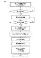
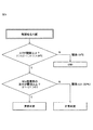
図3は、ECU7によって実行される、吸入空気量最大のときのNOx浄化率算出工程を示すフローチャートである。図4は、触媒温度最大のときのNOx浄化率算出工程を示すフローチャートである。図5は、得られたNOx浄化率に基づいて触媒劣化を診断する工程を示すフローチャートである。 FIG. 3 is a flow chart showing the NOx purification rate calculation process executed by the ECU 7 at the maximum intake air amount. FIG. 4 is a flowchart showing the NOx purification rate calculation process when the catalyst temperature is maximum. FIG. 5 is a flowchart showing steps of diagnosing catalyst deterioration based on the obtained NOx purification rate.
吸入空気量最大のときのNOx浄化率算出工程を説明すると、まず、図3に示すように、空気量センサ6により吸入空気量を確認する。そして吸入空気量が最大のときの値をGa(η1)に設定する。次いでGa(η1)におけるNOx浄化率(η1)を算出する。このNOx浄化率は、NOxセンサ5によって測定された入ガスと出ガス中のNOx濃度から、下式によって求める。
NOx浄化率=[(入ガスNOx濃度−出ガスNOx濃度)/入ガスNOx濃度]×100
ここで、入ガスNOx濃度−出ガスNOx濃度はNSR触媒に吸蔵されたNOx濃度を意味する。
To explain the NOx purification rate calculation process when the intake air amount is maximum, first, as shown in FIG. 3, the intake air amount is confirmed by the air amount sensor 6. Then, the value when the intake air amount is maximum is set to Ga ((1). Next, the NOx purification rate (η1) in Ga (η1) is calculated. The NOx purification rate is determined by the following equation from the NOx concentration in the inflow gas and the outflow gas measured by the
NOx purification rate = [(intake gas NOx concentration-exit gas NOx concentration) / inflow gas NOx concentration] × 100
Here, the inflow gas NOx concentration-the outflow gas NOx concentration means the NOx concentration stored in the NSR catalyst.
次に、入ガス温度センサ4により入ガス温度を確認し、触媒温度(触媒中心温度)を推定する。この触媒温度は、NSR触媒の温度を直に検出する温度検出装置を用いて検出してもよい。 Next, the inflow gas temperature is confirmed by the inflow gas temperature sensor 4 to estimate the catalyst temperature (the catalyst center temperature). The catalyst temperature may be detected using a temperature detection device that directly detects the temperature of the NSR catalyst.
最後に、Ga(η1)における触媒温度をT(η1)と設定し、終了する。 Finally, the catalyst temperature in Ga (η1) is set as T (η1), and the process ends.
次に、触媒温度最大のときのNOx浄化率算出工程を説明する。まず、図4に示すように、Ga(η1)におけるNOx浄化率(η1)を算出後、入ガス温度センサ4により入ガス温度を確認し、温度低下の有無を調べ、温度低下検出されれば、入ガス温度から、触媒温度(触媒中心温度)を推定し、この時の温度を触媒温度最大値としてT(η2)に設定する。次いでT(η2)におけるNOx浄化率(η2)を、η1と同様にして算出する。さらにT(η2)における吸入空気量をGa(η2)と設定し、終了する。 Next, the NOx purification rate calculation process at the maximum catalyst temperature will be described. First, as shown in FIG. 4, after calculating the NOx purification rate (η1) in Ga (η1), the gas temperature is checked by the gas temperature sensor 4 to check whether there is a temperature drop and if a temperature drop is detected The catalyst temperature (catalyst center temperature) is estimated from the incoming gas temperature, and the temperature at this time is set to T (η 2) as the catalyst temperature maximum value. Next, the NOx purification rate (η2) at T (η2) is calculated in the same manner as η1. Further, the intake air amount at T ((2) is set to Ga (η2), and the process is ended.
最後に、触媒の劣化診断の工程を説明する。図5に示すように、触媒温度最大値であるT(η2)とGa(η1)における触媒温度をT(η1)の温度差分(ΔT)を求め、閾値より高いか否かを判断する。この閾値は、十分な触媒劣化が認められる温度差であり、あらかじめ実験により求めてECUに記憶させておく。図5では閾値が34℃であり、この温度差分が34℃より高い場合、Ga(η1)におけるNOx浄化率(η1)とT(η2)におけるNOx浄化率(η2)の差分(η1−η2)を求め、この差分が閾値(図5では0.5)より高い場合に触媒は劣化していると診断する。この閾値もあらかじめ実験により求めてECUに記憶させておく。 Finally, the process of catalyst deterioration diagnosis will be described. As shown in FIG. 5, the temperature difference (.DELTA.T) between T (.eta.1) and the catalyst temperature at T (.eta.2) which is the catalyst temperature maximum value and Ga (.eta.1) is determined, and it is judged whether it is higher than a threshold. The threshold value is a temperature difference at which sufficient catalyst deterioration is recognized, and is obtained in advance by experiment and stored in the ECU. In FIG. 5, the threshold value is 34 ° C., and when this temperature difference is higher than 34 ° C., the difference (1−1−22) between the NOx purification rate (η1) for Ga (η1) and the NOx purification rate (η2) for T (η2) If the difference is higher than the threshold (0.5 in FIG. 5), the catalyst is diagnosed as being deteriorated. This threshold is also obtained in advance by experiment and stored in the ECU.
以上のような構成により、過渡運転時において、吸入空気量、触媒温度、NOx濃度を測定することにより、ECUにおいて触媒劣化を診断することができる。 With the above-described configuration, it is possible to diagnose catalyst deterioration in the ECU by measuring the amount of intake air, the catalyst temperature, and the NOx concentration during transient operation.
触媒の調製
(下層コート用スラリーの調製)
200gのイオン交換水に、Pt量で2g分のジニトロジアンモン白金硝酸溶液と、Pd量で0.2g分の硝酸パラジウム溶液を混合させた後、65gのアルミナ粉末を撹拌しながら混合した。次いで撹拌しながら加熱し、水分がなくなるまで蒸発させた後、得られた粉末を500℃にて2時間電気炉で焼成して、PtPd担持アルミナ粉末(1)を得た。
Preparation of Catalyst (Preparation of Slurry for Lower Coat)
After mixing 2 g of a dinitrodiammon platinum nitric acid solution in an amount of Pt with a palladium nitrate solution of 0.2 g in an amount of Pd in 200 g of ion exchanged water, 65 g of alumina powder was mixed with stirring. Next, the resultant was heated with stirring and evaporated until the water content disappeared, and the obtained powder was calcined in an electric furnace at 500 ° C. for 2 hours to obtain PtPd-loaded alumina powder (1).
また、300gのイオン交換水に酢酸バリウム28.1gを溶解させた後、5%ランタン添加酸化セリウム170gを加えて、撹拌しながら加熱し、水分がなくなるまで蒸発させ、得られた粉末を500℃にて2時間電気炉で焼成して、Ba担持CeO2粉末(2)を得た。 In addition, 28.1 g of barium acetate is dissolved in 300 g of ion-exchanged water, 170 g of 5% lanthanum-added cerium oxide is added, and the mixture is heated with stirring, and evaporated until the water disappears. The resultant was calcined in an electric furnace for 2 hours to obtain Ba-loaded CeO 2 powder (2).
300gのイオン交換水に、上記で得られたPtPd担持アルミナ粉末(1)67.2g及びBa担持CeO2粉末(2)191.72gを懸濁させ、アルミナバインダーを加えて、スラリーAを調製した。 67.2 g of PtPd-supported alumina powder (1) obtained above and 191.72 g of Ba-supported CeO 2 powder (2) were suspended in 300 g of ion exchanged water, and an alumina binder was added to prepare a slurry A. .
(上層コート用スラリーの調製)
100gのイオン交換水に、Pt量で0.6g分のジニトロジアンモン白金硝酸溶液と、Pd量で0.3g分の硝酸パラジウム溶液を混合させた後、30gのアルミナ粉末を撹拌しながら混合した。次いで撹拌しながら加熱し、水分がなくなるまで蒸発させた後、得られた粉末を500℃にて2時間電気炉で焼成して、PtPd担持アルミナ粉末(3)を得た。
(Preparation of upper layer coating slurry)
After mixing a 0.6 g portion of dinitrodiammon platinum nitric acid solution in an amount of Pt and a palladium nitrate solution amount of 0.3 g in an amount of Pd in 100 g of ion exchanged water, 30 g of alumina powder was mixed while stirring. . Subsequently, the resultant was heated with stirring and evaporated until the water content disappeared, and the obtained powder was calcined in an electric furnace at 500 ° C. for 2 hours to obtain PtPd-loaded alumina powder (3).
また、100gのイオン交換水にRh量で0.3g分の硝酸ロジウム溶液を混合させた後、30gのアルミナ粉末を撹拌しながら混合した。次いで撹拌しながら加熱し、水分がなくなるまで蒸発させ、得られた粉末を500℃にて2時間電気炉で焼成して、Rh担持アルミナ粉末(4)を得た。 Further, after a rhodium nitrate solution of 0.3 g in amount of Rh was mixed with 100 g of ion exchange water, 30 g of alumina powder was mixed while stirring. Then, the mixture was heated with stirring and evaporated until the water content disappeared, and the obtained powder was calcined in an electric furnace at 500 ° C. for 2 hours to obtain Rh-supporting alumina powder (4).
また、100gのイオン交換水に酢酸バリウム12.77gを溶解させた後、5%ランタン添加酸化セリウム45gを加えて、撹拌しながら加熱し、水分がなくなるまで蒸発させ、得られた粉末を500℃にて2時間電気炉で焼成して、Ba担持CeO2粉末(5)を得た。 In addition, 12.77 g of barium acetate is dissolved in 100 g of ion-exchanged water, 45 g of 5% lanthanum-added cerium oxide is added, and the mixture is heated with stirring, and evaporated until the water disappears. The resultant was calcined in an electric furnace for 2 hours to obtain Ba-loaded CeO 2 powder (5).
300gのイオン交換水に、上記で得られたPtPd担持アルミナ粉末(3)30.9g、Rh担持アルミナ粉末(4)30.3g及びBa担持CeO2粉末(5)54.87gを懸濁させ、アルミナバインダーを加えて、スラリーBを調製した。 Suspend 30.9 g of the PtPd-supported alumina powder (3) obtained above, 30.3 g of the Rh-supported alumina powder (4), and 54.87 g of the Ba-supported CeO 2 powder (5) in 300 g of ion-exchanged water, An alumina binder was added to prepare a slurry B.
(触媒のコーティング)
コージェライト製ハニカム基材(1.38L、400セル、4ミル)の上流側の一端から上記スラリーAを用いて全長の100%にあたる部分にウォッシュコートを施し、乾燥焼成することで下層コート部を形成した。さらにスラリーBを用いて、全長の100%にあたる部分にウォッシュコートを施し、乾燥焼成することで上層コート部を形成した。
(Catalyst coating)
Using the above-mentioned slurry A from the end on the upstream side of a cordierite honeycomb substrate (1.38 L, 400 cells, 4 mils), wash coat a portion corresponding to 100% of the total length, and dry and calcinate the lower layer coated portion It formed. Furthermore, using the slurry B, a washcoat was applied to a portion corresponding to 100% of the total length, and drying and baking were performed to form an upper coat portion.
(触媒の耐久)
2Lのディーゼルエンジンを用い、触媒温度680℃、62時間にてPM再生と硫黄被毒再生処理の繰り返し処理を行い、触媒の耐久処理を行い、正常触媒を得た。一方、触媒の劣化を判定するための触媒として、上記耐久処理を行った後、さらに浄化性能が低下するまで200時間耐久を継続し、劣化触媒を得た。
(Durable catalyst)
Using a 2 L diesel engine, repeated treatment of PM regeneration and sulfur poisoning regeneration treatment was performed at a catalyst temperature of 680 ° C. for 62 hours to carry out catalyst durability treatment to obtain a normal catalyst. On the other hand, as the catalyst for determining the deterioration of the catalyst, after performing the above-mentioned durability treatment, the durability was continued for 200 hours until the purification performance was lowered, and the deteriorated catalyst was obtained.
(触媒の評価)
得られた触媒を2Lのディーゼルエンジンの排気系に装着し、FTPモードに記載される加減速運転パターンにて過渡評価を行った。センサでの劣化判断と実際の触媒性能が一致することを確認するため、エンジン出の排ガスとNSR触媒出側の排ガスに含まれるNOx濃度を、ホリバ製、MEXA9100にて計測した。
(Evaluation of catalyst)
The obtained catalyst was attached to the exhaust system of a 2 L diesel engine, and transient evaluation was performed according to the acceleration / deceleration operation pattern described in the FTP mode. In order to confirm that the deterioration judgment by the sensor matches the actual catalyst performance, the NOx concentration contained in the exhaust gas from the engine and the exhaust gas on the NSR catalyst output side was measured by Horiba MEXA 9100.
正常触媒及び劣化触媒についての測定結果を以下の表1及び2に示す。 The measurement results for the normal catalyst and the deteriorated catalyst are shown in Tables 1 and 2 below.

さらに、これらの結果を図6及び図7にまとめる。図6に示すように、正常触媒及び劣化触媒において、触媒の温度差と吸入空気量の間の関係に相違はみられなかったが、図7に示すように、劣化触媒では、NOx吸蔵還元触媒の触媒中心温度が最大のときの温度と前記吸入空気量が最大のときの前記NOx吸蔵還元触媒の触媒中心温度の差分(ΔT)が34℃以上のとき、触媒中心温度が最大のときのNOx浄化率(η2)と吸入空気量が最大のときのNOx浄化率(η1)の差分が50%以上となっていた。 Furthermore, these results are summarized in FIG. 6 and FIG. As shown in FIG. 6, in the normal catalyst and the deteriorated catalyst, no difference was found in the relationship between the temperature difference of the catalyst and the amount of intake air, but as shown in FIG. When the difference (ΔT) between the temperature when the catalyst center temperature is maximum and the catalyst center temperature of the NOx storage reduction catalyst when the intake air amount is maximum is 34 ° C. or more, NOx when the catalyst center temperature is maximum The difference between the purification rate (η2) and the NOx purification rate (η1) when the intake air amount is maximum was 50% or more.
このように、本実施例に係る触媒劣化診断装置によれば、触媒中心温度が最大のときのNOx浄化率(η2)と吸入空気量が最大のときのNOx浄化率(η1)の差分により触媒劣化を診断することができる。 As described above, according to the catalyst deterioration diagnosis device according to the present embodiment, the catalyst is determined by the difference between the NOx purification rate (.eta.2) when the catalyst center temperature is maximum and the NOx purification rate (.eta.1) when the intake air amount is maximum. Deterioration can be diagnosed.
1 内燃機関
2 NSR触媒
3 SCR触媒
4 入ガス温度センサ
5 NOxセンサ
6 空気量センサ
7 ECU
8 排気通路
1
8 Exhaust passage
Claims (6)
前記内燃機関への吸入空気量を検出する吸入空気量検出装置と、
前記NOx吸蔵還元触媒を流通する排ガスの温度を検出する排ガス温度検出装置と、
前記NOx吸蔵還元触媒に流入する排ガス及び前記NOx吸蔵還元触媒から流出する排ガスのNOxを検出し、それによってNOx浄化率を検出する、NOx浄化率検出装置と、
前記内燃機関への前記吸入空気量の流量の増加に続いて、前記NOx吸蔵還元触媒を流通する排ガスの前記温度が上昇し、それによって前記NOx吸蔵還元触媒の温度が第一の所定の閾値よりも大きく上昇するときに、このNOx吸蔵還元触媒の温度の上昇の前後の前記NOx浄化率の差を算出し、このNOx浄化率の差が第二の所定の閾値よりも大きい場合に、前記NOx吸蔵還元触媒が劣化していると診断する診断装置と
を備える劣化診断装置。 A NOx storage reduction catalyst degradation diagnosis device for purifying exhaust gas from an internal combustion engine, comprising:
An intake air amount detection device for detecting an intake air amount to the internal combustion engine;
An exhaust gas temperature detection device for detecting the temperature of the exhaust gas flowing through the NOx storage reduction catalyst;
A NOx purification rate detection device that detects NOx of exhaust gas flowing into the NOx storage reduction catalyst and exhaust gas flowing out from the NOx storage reduction catalyst, thereby detecting a NOx purification rate;
Following the increase in the flow rate of the intake air amount to the internal combustion engine, the temperature of the exhaust gas flowing through the NOx storage reduction catalyst rises, whereby the temperature of the NOx storage reduction catalyst is higher than a first predetermined threshold value When the difference between the NOx purification rates before and after the rise of the temperature of the NOx storage reduction catalyst is calculated, and the difference between the NOx purification rates is larger than a second predetermined threshold value, the NOx And a diagnostic device that diagnoses that the storage and reduction catalyst is degraded.
前記内燃機関への吸入空気量の流量の増加に続いて前記NOx吸蔵還元触媒を流通する排ガスの温度が上昇し、かつ前記内燃機関への吸入空気量の流量が最大のときの前記温度と、前記NOx吸蔵還元触媒を流通する排ガスの温度が最高になるときの前記温度との差が、所定の閾値よりも大きくなるときに、
前記内燃機関への吸入空気量の流量が最大のときのNOx浄化率と、前記NOx吸蔵還元触媒を流通する排ガスの温度が最高になるときのNOx浄化率との差を算出し、このNOx浄化率の差が所定の閾値よりも大きい場合に、前記NOx吸蔵還元触媒が劣化していると診断する、
請求項1に記載の劣化診断装置。 The diagnostic device
Following the increase of the flow rate of the intake air amount to the internal combustion engine, the temperature of the exhaust gas flowing through the NOx storage reduction catalyst rises, and the temperature when the flow rate of the intake air amount to the internal combustion engine is maximum; When the difference between the temperature of the exhaust gas flowing through the NOx storage reduction catalyst and the temperature when the temperature of the exhaust gas reaches a maximum becomes larger than a predetermined threshold value,
The difference between the NOx purification rate when the flow rate of the intake air amount to the internal combustion engine is maximum and the NOx purification rate when the temperature of the exhaust gas flowing through the NOx storage reduction catalyst is maximum is calculated, and this NOx purification Diagnosing that the NOx storage reduction catalyst is deteriorated if the difference in the rates is larger than a predetermined threshold value;
The degradation diagnostic device according to claim 1.
NOx浄化率=[(入ガスNOx濃度−出ガスNOx濃度)/入ガスNOx濃度]×100 The deterioration diagnosis device according to claim 1, wherein the NOx purification rate detection device calculates the NOx purification rate by the following formula:
NOx purification rate = [(intake gas NOx concentration-exit gas NOx concentration) / inflow gas NOx concentration] × 100
Priority Applications (2)
| Application Number | Priority Date | Filing Date | Title |
|---|---|---|---|
| JP2017104886A JP6536623B2 (en) | 2017-05-26 | 2017-05-26 | Deterioration diagnosis device for NOx storage reduction catalyst |
| US15/952,862 US10385753B2 (en) | 2017-05-26 | 2018-04-13 | Apparatus for diagnosing deterioration of NOx storage-reduction catalyst |
Applications Claiming Priority (1)
| Application Number | Priority Date | Filing Date | Title |
|---|---|---|---|
| JP2017104886A JP6536623B2 (en) | 2017-05-26 | 2017-05-26 | Deterioration diagnosis device for NOx storage reduction catalyst |
Publications (2)
| Publication Number | Publication Date |
|---|---|
| JP2018200021A JP2018200021A (en) | 2018-12-20 |
| JP6536623B2 true JP6536623B2 (en) | 2019-07-03 |
Family
ID=64400581
Family Applications (1)
| Application Number | Title | Priority Date | Filing Date |
|---|---|---|---|
| JP2017104886A Expired - Fee Related JP6536623B2 (en) | 2017-05-26 | 2017-05-26 | Deterioration diagnosis device for NOx storage reduction catalyst |
Country Status (2)
| Country | Link |
|---|---|
| US (1) | US10385753B2 (en) |
| JP (1) | JP6536623B2 (en) |
Families Citing this family (10)
| Publication number | Priority date | Publication date | Assignee | Title |
|---|---|---|---|---|
| US10920645B2 (en) * | 2018-08-02 | 2021-02-16 | Ford Global Technologies, Llc | Systems and methods for on-board monitoring of a passive NOx adsorption catalyst |
| JP2020060120A (en) * | 2018-10-09 | 2020-04-16 | 日本碍子株式会社 | Deterioration diagnosis device of catalyst and deterioration diagnosis method of catalyst |
| JP7283444B2 (en) | 2020-06-03 | 2023-05-30 | 株式会社豊田自動織機 | engine system |
| US11636870B2 (en) | 2020-08-20 | 2023-04-25 | Denso International America, Inc. | Smoking cessation systems and methods |
| US11932080B2 (en) | 2020-08-20 | 2024-03-19 | Denso International America, Inc. | Diagnostic and recirculation control systems and methods |
| US11813926B2 (en) | 2020-08-20 | 2023-11-14 | Denso International America, Inc. | Binding agent and olfaction sensor |
| US11881093B2 (en) | 2020-08-20 | 2024-01-23 | Denso International America, Inc. | Systems and methods for identifying smoking in vehicles |
| US11828210B2 (en) | 2020-08-20 | 2023-11-28 | Denso International America, Inc. | Diagnostic systems and methods of vehicles using olfaction |
| US11760170B2 (en) | 2020-08-20 | 2023-09-19 | Denso International America, Inc. | Olfaction sensor preservation systems and methods |
| US11760169B2 (en) | 2020-08-20 | 2023-09-19 | Denso International America, Inc. | Particulate control systems and methods for olfaction sensors |
Family Cites Families (10)
| Publication number | Priority date | Publication date | Assignee | Title |
|---|---|---|---|---|
| JP3799770B2 (en) * | 1997-09-18 | 2006-07-19 | トヨタ自動車株式会社 | Catalyst deterioration diagnosis device for internal combustion engine |
| JP4092485B2 (en) | 2003-04-01 | 2008-05-28 | 日産自動車株式会社 | Exhaust gas purification catalyst deterioration diagnosis device |
| JP2005330848A (en) | 2004-05-18 | 2005-12-02 | Mitsubishi Motors Corp | Catalyst degradation estimating device |
| JP4729518B2 (en) | 2007-03-07 | 2011-07-20 | トヨタ自動車株式会社 | NOx catalyst deterioration diagnosis device |
| JP5673803B2 (en) * | 2011-04-12 | 2015-02-18 | トヨタ自動車株式会社 | Selective reduction type NOx catalyst deterioration detection device |
| JP2013019401A (en) | 2011-07-14 | 2013-01-31 | Toyota Motor Corp | Catalyst deterioration determination system |
| JP5601285B2 (en) | 2011-07-19 | 2014-10-08 | トヨタ自動車株式会社 | Catalyst deterioration judgment system |
| JP2013181453A (en) | 2012-03-01 | 2013-09-12 | Toyota Motor Corp | Catalyst deterioration determination system |
| US9670812B2 (en) * | 2012-06-22 | 2017-06-06 | Toyota Jidosha Kabushiki Kaisha | Deterioration detection system for exhaust gas purification apparatus |
| JP5708593B2 (en) | 2012-08-06 | 2015-04-30 | 株式会社デンソー | Catalyst deterioration diagnosis device |
-
2017
- 2017-05-26 JP JP2017104886A patent/JP6536623B2/en not_active Expired - Fee Related
-
2018
- 2018-04-13 US US15/952,862 patent/US10385753B2/en not_active Expired - Fee Related
Also Published As
| Publication number | Publication date |
|---|---|
| US20180340459A1 (en) | 2018-11-29 |
| JP2018200021A (en) | 2018-12-20 |
| US10385753B2 (en) | 2019-08-20 |
Similar Documents
| Publication | Publication Date | Title |
|---|---|---|
| JP6536623B2 (en) | Deterioration diagnosis device for NOx storage reduction catalyst | |
| JP3430879B2 (en) | Exhaust gas purification device for internal combustion engine | |
| EP2173983B1 (en) | Exhaust gas purifying system | |
| EP3056698B1 (en) | Method for monitoring a particulate filter | |
| US20120191288A1 (en) | On-board diagnostics system and method | |
| JP6287989B2 (en) | Abnormality diagnosis device for NOx storage reduction catalyst | |
| US8794057B2 (en) | Diagnostic operation strategy for diesel oxidation catalyst aging level determination using NOx sensor NO2 interference | |
| US8839612B2 (en) | Method for operating an exhaust system of an internal combustion engine | |
| JP2007332881A (en) | Exhaust emission control device and exhaust emission control method using this device | |
| EP1064985A2 (en) | Exhaust gas purifying system | |
| GB2520174A (en) | An on-board diagnostics system for catalyzed substrate | |
| EP3382172B1 (en) | Abnormality diagnosis apparatus for exhaust gas purification apparatus | |
| JP6102908B2 (en) | Exhaust purification device deterioration diagnosis device | |
| JP7169826B2 (en) | Catalyst deterioration diagnosis system and catalyst deterioration diagnosis method | |
| EP3943721A1 (en) | Ammonia storage capacity of scr catalyst unit | |
| EP3943729A1 (en) | Methods for diagnostics and operation of an emissions aftertreatment system | |
| JP4453700B2 (en) | Exhaust gas purification device for internal combustion engine | |
| KR20200095295A (en) | After treatment system and after treatment method for lean-burn engine | |
| EP3364013A1 (en) | Internal combustion engine and control method for internal combustion engine | |
| JP2003269146A (en) | Exhaust emission control device for internal combustion engine | |
| JP6988648B2 (en) | Exhaust purification device for internal combustion engine | |
| EP3431728B1 (en) | Abnormality diagnosis system for exhaust gas purification apparatus | |
| JP4333612B2 (en) | Exhaust gas purification device and exhaust gas purification catalyst | |
| JP2003293844A (en) | Deterioration diagnosing device for oxygen concentration sensor | |
| JP2004028041A (en) | Exhaust emission control system and method |
Legal Events
| Date | Code | Title | Description |
|---|---|---|---|
| A977 | Report on retrieval |
Free format text: JAPANESE INTERMEDIATE CODE: A971007 Effective date: 20190418 |
|
| TRDD | Decision of grant or rejection written | ||
| A01 | Written decision to grant a patent or to grant a registration (utility model) |
Free format text: JAPANESE INTERMEDIATE CODE: A01 Effective date: 20190507 |
|
| A61 | First payment of annual fees (during grant procedure) |
Free format text: JAPANESE INTERMEDIATE CODE: A61 Effective date: 20190520 |
|
| R151 | Written notification of patent or utility model registration |
Ref document number: 6536623 Country of ref document: JP Free format text: JAPANESE INTERMEDIATE CODE: R151 |
|
| LAPS | Cancellation because of no payment of annual fees |