JP6536070B2 - Battery monitoring device - Google Patents
Battery monitoring device Download PDFInfo
- Publication number
- JP6536070B2 JP6536070B2 JP2015031452A JP2015031452A JP6536070B2 JP 6536070 B2 JP6536070 B2 JP 6536070B2 JP 2015031452 A JP2015031452 A JP 2015031452A JP 2015031452 A JP2015031452 A JP 2015031452A JP 6536070 B2 JP6536070 B2 JP 6536070B2
- Authority
- JP
- Japan
- Prior art keywords
- current
- voltage
- value
- battery
- measurement
- Prior art date
- Legal status (The legal status is an assumption and is not a legal conclusion. Google has not performed a legal analysis and makes no representation as to the accuracy of the status listed.)
- Expired - Fee Related
Links
- 238000012806 monitoring device Methods 0.000 title claims description 16
- 238000012545 processing Methods 0.000 claims description 132
- 238000005259 measurement Methods 0.000 claims description 104
- 230000005540 biological transmission Effects 0.000 claims description 22
- 238000004364 calculation method Methods 0.000 claims description 20
- 238000012544 monitoring process Methods 0.000 claims description 8
- 238000001514 detection method Methods 0.000 description 25
- 238000004891 communication Methods 0.000 description 18
- 238000000034 method Methods 0.000 description 16
- 238000012417 linear regression Methods 0.000 description 13
- 238000005070 sampling Methods 0.000 description 10
- 238000007599 discharging Methods 0.000 description 6
- 238000013500 data storage Methods 0.000 description 4
- 230000008054 signal transmission Effects 0.000 description 4
- 238000010586 diagram Methods 0.000 description 3
- 238000012986 modification Methods 0.000 description 2
- 230000004048 modification Effects 0.000 description 2
- 238000012360 testing method Methods 0.000 description 2
- HBBGRARXTFLTSG-UHFFFAOYSA-N Lithium ion Chemical compound [Li+] HBBGRARXTFLTSG-UHFFFAOYSA-N 0.000 description 1
- 229910001416 lithium ion Inorganic materials 0.000 description 1
- 238000007726 management method Methods 0.000 description 1
- 230000009466 transformation Effects 0.000 description 1
Images


Classifications
-
- Y—GENERAL TAGGING OF NEW TECHNOLOGICAL DEVELOPMENTS; GENERAL TAGGING OF CROSS-SECTIONAL TECHNOLOGIES SPANNING OVER SEVERAL SECTIONS OF THE IPC; TECHNICAL SUBJECTS COVERED BY FORMER USPC CROSS-REFERENCE ART COLLECTIONS [XRACs] AND DIGESTS
- Y02—TECHNOLOGIES OR APPLICATIONS FOR MITIGATION OR ADAPTATION AGAINST CLIMATE CHANGE
- Y02E—REDUCTION OF GREENHOUSE GAS [GHG] EMISSIONS, RELATED TO ENERGY GENERATION, TRANSMISSION OR DISTRIBUTION
- Y02E60/00—Enabling technologies; Technologies with a potential or indirect contribution to GHG emissions mitigation
- Y02E60/10—Energy storage using batteries
Landscapes
- Connection Of Batteries Or Terminals (AREA)
- Testing Of Short-Circuits, Discontinuities, Leakage, Or Incorrect Line Connections (AREA)
- Measurement Of Resistance Or Impedance (AREA)
- Tests Of Electric Status Of Batteries (AREA)
- Charge And Discharge Circuits For Batteries Or The Like (AREA)
- Secondary Cells (AREA)
Description
本発明は、電池監視装置に関する。 The present invention relates to a battery monitoring device.
下記特許文献1には、複数の二次電池からなる組電池と負荷とをバスバーとボルトとで接続する電池システムにおいて、ボルトによる締め付けの緩み(連結緩み)を早期に判定する技術が記載されている。この電池システムは、複数の電圧計が取得した各二次電池の端子間電圧と単一の電流計が取得した負荷電流とをパラメータ検出部に入力してデジタル信号化し、当該デジタル信号である各端子間電圧パラメータ及び電流パラメータをBMU(Battery Management Unit)に供給し、当該BMUにおいて各端子間電圧パラメータ及び電流パラメータに基づいて各ボルト接続部における接触抵抗を演算することにより結線緩みの発生を判定している。 Patent Document 1 below describes a technique for early determination of looseness (connection looseness) of tightening by bolts in a battery system in which a battery pack including a plurality of secondary batteries and a load are connected by a bus bar and a bolt. There is. In this battery system, the voltage between terminals of each secondary battery acquired by a plurality of voltmeters and the load current acquired by a single ammeter are input to the parameter detection unit to be digitized and each digital signal Inter-terminal voltage parameter and current parameter are supplied to BMU (Battery Management Unit), and occurrence of loose connection is judged by calculating contact resistance at each bolt connection based on each inter-terminal voltage parameter and current parameter in BMU doing.
ところで、上記接触抵抗を正確に評価することは結線緩みの発生を正確に判定するために必要不可欠な事項である。しかしながら、上記従来技術では、複数の電圧計からBMUまでの電圧信号伝送時間と電流計からBMUまでの電流信号伝送時間のずれを考慮していないため、接触抵抗を正確に評価することができない。 Accurately evaluating the contact resistance is an indispensable matter in order to accurately determine the occurrence of loose connection. However, in the above-mentioned prior art, the contact resistance can not be evaluated accurately because the voltage signal transmission time from the plurality of voltmeters to the BMU and the current signal transmission time from the ammeter to the BMU are not taken into consideration.
すなわち、電圧信号伝送時間と電流信号伝送時間とが所定時間ずれていた場合、BMUは異なる時間に計測された端子間電圧と負荷電流とに基づいて接触抵抗を演算することになるが、所定時間において端子間電圧あるいは負荷電流が変動した場合には、正確な接触抵抗を演算することができない。 That is, when the voltage signal transmission time and the current signal transmission time deviate from each other by a predetermined time, the BMU calculates the contact resistance based on the voltage between the terminals measured at different times and the load current. In the case where the voltage between terminals or the load current fluctuates, the accurate contact resistance can not be calculated.
本発明は、上述した事情に鑑みてなされたものであり、電池システムにおける接触抵抗を従来よりも正確に評価することを目的とするものである。 The present invention has been made in view of the above-described circumstances, and an object thereof is to evaluate contact resistance in a battery system more accurately than in the past.
上記目的を達成するために、本発明では、第1の解決手段として、電池ユニット端子と電力伝送部材とがボルト接続され、電力伝送部材を介して外部に電力を供給する電池システムの状態を監視する電池監視装置であって、電池システムの電圧を順次計測する電圧計測手段と、電池システムに流れる電流を順次計測する電流計測手段と、電流しきい値よりも小さい電流が計測される期間における電圧計測手段の計測値及び電流計測手段の計測値を除外した電圧計測手段の計測値及び電流計測手段の計測値を用いて電池ユニット端子と電力伝送部材とのボルト接続部の接触抵抗を演算する接触抵抗演算手段とを具備する、という手段を採用する。 In order to achieve the above object, according to the present invention, as a first solution, a battery unit terminal and a power transmission member are connected by bolts, and a state of a battery system supplying power to the outside through the power transmission member is monitored. A battery monitoring device that measures voltage of the battery system sequentially, current measuring device that sequentially measures the current flowing through the battery system, and voltage during a period when a current smaller than the current threshold is measured Contact that calculates the contact resistance of the bolt connection between the battery unit terminal and the power transmission member using the measurement value of the voltage measurement means excluding the measurement value of the measurement means and the measurement value of the current measurement means and the measurement value of the current measurement means And means for providing resistance calculation means.
本発明では、第2の解決手段として、上記第1の解決手段において、接触抵抗演算手段は、変化率しきい値よりも大きい変化率の電流が計測される期間における電圧計測手段の計測値及び電流計測手段の計測値を除外した電圧計測手段の計測値及び電流計測手段の計測値を用いて電池ユニット端子と電力伝送部材との接触抵抗を演算する、という手段を採用する。 In the present invention, as the second solution means, in the first solution means, the contact resistance calculation means is a measurement value of the voltage measurement means in a period during which a current of a change rate larger than the change rate threshold is measured A means is employed to calculate the contact resistance between the battery unit terminal and the power transmission member using the measurement value of the voltage measurement means excluding the measurement value of the current measurement means and the measurement value of the current measurement means.
本発明では、第3の解決手段として、上記第1または第2の解決手段において、接触抵抗演算手段は、電圧計測手段の計測値及び電流計測手段の計測値に基づいて電圧及び電流に関する回帰直線を求め、当該回帰直線の傾きに基づいて接触抵抗を求める、という手段を採用する。 In the present invention, as the third solution means, in the first or second solution means, the contact resistance calculation means is a regression line regarding voltage and current based on the measurement value of the voltage measurement means and the measurement value of the current measurement means. And the contact resistance is determined based on the slope of the regression line.
本発明では、第4の解決手段として、上記第3の解決手段において、接触抵抗演算手段は、予め電圧計測手段の計測値及び電流計測手段の計測値に基づいて基準データとして回帰直線を求め、基準データとの比較に基づいてボルト接続部の緩みを判断する、という手段を採用する。 In the present invention, as the fourth solution means, in the third solution means, the contact resistance calculation means obtains in advance a regression line as reference data based on the measurement value of the voltage measurement means and the measurement value of the current measurement means A means is employed to determine the looseness of the bolted connection based on comparison with the reference data.
本発明では、第5の解決手段として、上記第4の解決手段において、接触抵抗演算手段は、電流計測手段の計測値及び基準データに基づいて求めた電圧値と、電圧計測手段の計測値とを比較し、比較結果に基づいてボルト接続部の緩みを判断する、という手段を採用する。 In the present invention, as the fifth solution means, in the fourth solution means, the contact resistance calculation means comprises a voltage value obtained based on the measurement value of the current measurement means and the reference data, and the measurement value of the voltage measurement means. Are adopted to determine the looseness of the bolt connection based on the comparison result.
本発明では、第6の解決手段として、上記第4の解決手段において、接触抵抗演算手段は、電圧計測手段の計測値及び電流計測手段の計測値に基づいて回帰直線を求め、該回帰直線と、基準データとの傾きを比較し、比較結果に基づいてボルト接続部の緩みを判断する、という手段を採用する。 In the present invention, as a sixth solution, in the fourth solution, the contact resistance calculation means determines a regression line based on the measurement value of the voltage measurement means and the measurement value of the current measurement means, and And means for comparing inclination with reference data and judging looseness of the bolt connection based on the comparison result.
本発明では、第7の解決手段として、上記第2の解決手段において、接触抵抗演算手段は、電圧計測手段の計測値及び電流計測手段の計測値をローパスフィルタ処理することにより、電流しきい値よりも小さく、かつ、変化率しきい値よりも大きい変化率の電流が計測される期間における電圧計測手段の計測値及び電流計測手段の計測値を除外する、という手段を採用する。 In the present invention, as the seventh solution means, in the second solution means, the contact resistance calculation means performs low-pass filter processing on the measurement value of the voltage measurement means and the measurement value of the current measurement means. A means is employed which excludes the measured value of the voltage measuring means and the measured value of the current measuring means in a period during which a current smaller than the change rate and larger than the change rate threshold value is measured.
本発明では、第8の解決手段として、上記第1〜第7のいずれかの解決手段において、電池が複数の二次電池ユニットの電池ユニット端子を電力伝送部材を介してボルト接続したものである場合、電圧計測手段は、電池ユニット端子によるボルト接続部に対して設けられると共に、電池ユニット端子によるボルト接続部に対して設けられる、という手段を採用する。 In the present invention, as an eighth solution means, in any one of the first to seventh solution means, a battery has a battery unit terminal of a plurality of secondary battery units bolted through a power transmission member. In this case, the voltage measuring means is provided to the bolt connection portion by the battery unit terminal and to the bolt connection portion by the battery unit terminal.
本発明では、第9の解決手段として、上記第1〜第8のいずれかの解決手段において、電圧計測手段は、電力伝送部材による各々のボルト接続部に対して設けられ、接触抵抗演算手段は、ボルト接続部の各々について接触抵抗を演算する、という手段を採用する。 In the present invention, as a ninth solution means according to any one of the first to eighth solution means, the voltage measurement means is provided for each bolt connection portion by the power transmission member, and the contact resistance calculation means is And means for calculating the contact resistance for each of the bolt connections.
本発明によれば、接触抵抗演算手段は、電圧計測手段の計測値及び電流計測手段の計測値のうち、電流しきい値よりも小さい電流が計測される期間における電圧計測手段の計測値及び電流計測手段の計測値を除外してボルト接続部の接触抵抗を演算するので、電池システムにおける接触抵抗を従来よりも正確に評価することが可能である。すなわち、電流しきい値よりも小さい電流が計測される期間における電圧計測手段の計測値及び電流計測手段の計測値は各々に値が小さいため、電圧計測手段から接触抵抗演算手段までの計測値の伝送時間と電流計測手段から接触抵抗演算手段までの計測値の伝送時間との間にずれが生じた場合に、接触抵抗の判定に与える影響が電流が上記電流しきい値よりも大きい場合よりも大きい。また、電流しきい値よりも小さい電流が計測される期間における電圧計測手段の計測値及び電流計測手段の計測値は各々に値が小さいため、計測誤差の影響も大きい。したがって、本発明によれば、電流の大小に依らず全ての計測値を用いて接触抵抗を演算する従来技術に比較して、電池システムにおける接触抵抗を正確に評価することが可能である。 According to the present invention, the contact resistance calculation means comprises, among the measurement value of the voltage measurement means and the measurement value of the current measurement means, the measurement value of the voltage measurement means and the current during a period in which a current smaller than the current threshold is measured. Since the contact resistance of the bolt connection is calculated excluding the measurement value of the measurement means, it is possible to evaluate the contact resistance in the battery system more accurately than before. That is, since the measured value of the voltage measuring means and the measured value of the current measuring means in a period during which a current smaller than the current threshold is measured have a smaller value, the measured value from the voltage measuring means to the contact resistance calculating means is When a shift occurs between the transmission time and the transmission time of the measured value from the current measurement means to the contact resistance calculation means, the influence on the determination of the contact resistance is greater than when the current is larger than the above current threshold value large. In addition, since the measurement value of the voltage measurement means and the measurement value of the current measurement means during the period when the current smaller than the current threshold value is measured are respectively small in value, the influence of the measurement error is large. Therefore, according to the present invention, it is possible to accurately evaluate the contact resistance in the battery system as compared with the prior art in which the contact resistance is calculated using all the measurement values regardless of the magnitude of the current.
以下、図面を参照して、本発明の実施形態について説明する。
本実施形態における電池システムAは、例えば、船舶に搭載され、電力変換器Dcを介して船舶に搭載される各種負荷Ldへの放電処理や、図示しない発電機や充電器から供給される電力の充電処理を行う。
Hereinafter, embodiments of the present invention will be described with reference to the drawings.
The battery system A in the present embodiment is, for example, mounted on a ship, discharge processing to various loads Ld mounted on the ship through the power converter Dc, and power supplied from a generator and a charger (not shown). Perform charge processing.
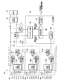
電池システムAは、図1に示すように、電池モジュールM1,M2,M3、電流センサY(電流計測手段)、電圧センサD(電圧計測手段)、バスバーBs1〜Bs4及びデータ処理部Ksを備える。なお、バスバーBs1及びバスバーBs4は、本実施形態における電力伝送部材である。また、バスバーBs2及びバスバーBs3は、本実施形態における第2電力伝送部材である。 As shown in FIG. 1, the battery system A includes battery modules M1, M2 and M3, a current sensor Y (current measurement means), a voltage sensor D (voltage measurement means), bus bars Bs1 to Bs4, and a data processing unit Ks. The bus bar Bs1 and the bus bar Bs4 are power transmission members in the present embodiment. The bus bar Bs2 and the bus bar Bs3 are a second power transmission member in the present embodiment.
電池モジュールM1,M2,M3は、二次電池ユニットU1,U2,U3を構成する電池セルb11〜b13,b21〜b23,b31〜b33各々の電圧を検出し、該電圧を示すセル電圧データを出力する。なお、電池モジュールM1,M2,M3は同じ構成であるので、詳細な説明は電池モジュールM1について行い、電池モジュールM2,M3については省略する。 Battery modules M1, M2 and M3 detect voltages of battery cells b11 to b13, b21 to b23 and b31 to b33 constituting secondary battery units U1, U2 and U3, and output cell voltage data indicating the voltages. Do. In addition, since the battery modules M1, M2, and M3 have the same configuration, the detailed description will be given for the battery module M1, and the battery modules M2 and M3 will be omitted.
電池モジュールM1は、一対の電池ユニット端子T11,T12、二次電池ユニットU1、セル電圧計測部Sk1(電圧計測手段)及び通信処理部Ts1備える。一対の電池ユニット端子T11,T12は、電池セルb11〜b13の電力を二次電池ユニットU1の外部に出力するための端子である。電池ユニット端子T11は、バスバーBs1を介して、電力変換器Dcの電池端子DT1に接続されている。一方、電池ユニット端子T12は、バスバーBs2を介して、電池モジュールM2の電池ユニット端子T21に接続されている。 The battery module M1 includes a pair of battery unit terminals T11 and T12, a secondary battery unit U1, a cell voltage measurement unit Sk1 (voltage measurement unit), and a communication processing unit Ts1. The pair of battery unit terminals T11 and T12 are terminals for outputting the power of the battery cells b11 to b13 to the outside of the secondary battery unit U1. The battery unit terminal T11 is connected to the battery terminal DT1 of the power converter Dc via the bus bar Bs1. On the other hand, the battery unit terminal T12 is connected to the battery unit terminal T21 of the battery module M2 via the bus bar Bs2.
二次電池ユニットU1は、リチウムイオン電池や鉛蓄池等の二次電池である3個の電池セルb11,b12,b13からなり、電池セルb11,b12,b13が直列に接続されるユニットである。セル電圧計測部Sk1は、電池セルb11〜b13それぞれの電圧を検出し、検出結果をデジタル変換し、電池セルb11〜b13それぞれの電圧を示すセル電圧データを通信処理部Ts1に出力する。通信処理部Ts1は、電池モジュールM2に設けられる通信処理部Ts2に接続され、セル電圧計測部Sk1から入力されるセル電圧データを通信処理部Ts2に出力する。なお、本実施形態では、電池セルb11〜b13個々の電圧を検出するセル電圧計測部Sk1を使用しているが、セル電圧計測部Sk1に代わって二次電池ユニットU1の電圧を検出するユニット電圧計測部を使用してもよい。 The secondary battery unit U1 is a unit including three battery cells b11, b12 and b13 which are secondary batteries such as lithium ion batteries and lead storage batteries, and the battery cells b11, b12 and b13 are connected in series. . The cell voltage measurement unit Sk1 detects the voltage of each of the battery cells b11 to b13, converts the detection result into a digital value, and outputs cell voltage data indicating the voltage of each of the battery cells b11 to b13 to the communication processing unit Ts1. The communication processing unit Ts1 is connected to the communication processing unit Ts2 provided in the battery module M2, and outputs the cell voltage data input from the cell voltage measurement unit Sk1 to the communication processing unit Ts2. In the present embodiment, the cell voltage measurement unit Sk1 that detects individual voltages of the battery cells b11 to b13 is used, but a unit voltage that detects the voltage of the secondary battery unit U1 instead of the cell voltage measurement unit Sk1. A measuring unit may be used.
また、電池モジュールM2において、通信処理部Ts2は、通信処理部Ts1から入力されるセル電圧データと、電池モジュールM2に設けられるセル電圧計測部Sk2から入力されると共に二次電池ユニットU2の電池セルb21〜b23それぞれの電圧を示すセル電圧データとを、電池モジュールM3に設けられる通信処理部Ts3に出力する。 Further, in the battery module M2, the communication processing unit Ts2 receives the cell voltage data input from the communication processing unit Ts1 and the cell voltage measurement unit Sk2 provided in the battery module M2, and receives the battery cells of the secondary battery unit U2. The cell voltage data indicating the voltage of each of b21 to b23 is output to the communication processing unit Ts3 provided in the battery module M3.
また、電池モジュールM3において、通信処理部Ts3は、通信処理部Ts2から入力されるセル電圧データと、電池モジュールM3に設けられるセル電圧計測部Sk3から入力される二次電池ユニットU3の電池セルb31〜b33それぞれの電圧を示すセル電圧データとを、データ処理部Ksに出力する。つまり、通信処理部Ts3は、電池セルb11〜b13,b21〜b23,b31〜b33各々の電圧を示すセル電圧データを、データ処理部Ksに順次出力する。また、電池セルb11〜b13,b21〜b23,b31〜b33は、直列に接続されている。 In the battery module M3, the communication processing unit Ts3 receives the cell voltage data input from the communication processing unit Ts2 and the battery cell b31 of the secondary battery unit U3 input from the cell voltage measurement unit Sk3 provided in the battery module M3. The cell voltage data indicating each voltage of ̃b33 is output to the data processing unit Ks. That is, the communication processing unit Ts3 sequentially outputs cell voltage data indicating the voltages of the battery cells b11 to b13, b21 to b23, and b31 to b33 to the data processing unit Ks. The battery cells b11 to b13, b21 to b23, and b31 to b33 are connected in series.
また、電池モジュールM2において、一対の電池ユニット端子T21,T22のうち、電池ユニット端子T21は、バスバーBs2を介して、電池モジュールM1の電池ユニット端子T12に接続されている。一方、電池ユニット端子T22は、バスバーBs3を介して、電池モジュールM3の電池ユニット端子31に接続されている。また、電池モジュールM3において、一対の電池ユニット端子T31,T32のうち、電池ユニット端子T31は、上述したように、バスバーBs3を介して、電池モジュールM2の電池ユニット端子T22に接続されている。一方、電池ユニット端子T32は、バスバーBs4を介して、電力変換器Dcの一対の電池端子DT1,DT2のうち、電池端子DT2に接続されている。 Further, in the battery module M2, of the pair of battery unit terminals T21 and T22, the battery unit terminal T21 is connected to the battery unit terminal T12 of the battery module M1 via the bus bar Bs2. On the other hand, the battery unit terminal T22 is connected to the battery unit terminal 31 of the battery module M3 via the bus bar Bs3. Further, in the battery module M3, of the pair of battery unit terminals T31 and T32, as described above, the battery unit terminal T31 is connected to the battery unit terminal T22 of the battery module M2 via the bus bar Bs3. On the other hand, the battery unit terminal T32 is connected to the battery terminal DT2 of the pair of battery terminals DT1, DT2 of the power converter Dc via the bus bar Bs4.
バスバーBs1(電力伝送部材)は、一端が電池モジュールM1の電池ユニット端子T11に接続され、他端が電力変換器Dcの電池端子DT1に接続される。バスバーBs2(第2電力伝送部材)は、一端が電池モジュールM1の電池ユニット端子T12に接続され、他端が電池モジュールM2の電池ユニット端子T21に接続されている。バスバーBs3(第2電力伝送部材)は、一端が電池モジュールM2の電池ユニット端子T22に接続され、他端が電池モジュールM3の電池ユニット端子T31に接続されている。バスバーBs4(電力伝送部材)は、一端が電池モジュールM3の電池ユニット端子T32に接続され、他端が電力変換器Dcの電池端子DT2に接続されている。上述した電池ユニット端子T11,T12、電池ユニット端子T21,T22、電池ユニット端子T31,T32及び電池端子DT1,DT2と、バスバーBs1〜Bs4とは、ボルトによって接続されている。 One end of the bus bar Bs1 (power transmission member) is connected to the battery unit terminal T11 of the battery module M1, and the other end is connected to the battery terminal DT1 of the power converter Dc. One end of the bus bar Bs2 (second power transmission member) is connected to the battery unit terminal T12 of the battery module M1, and the other end is connected to the battery unit terminal T21 of the battery module M2. One end of the bus bar Bs3 (second power transmission member) is connected to the battery unit terminal T22 of the battery module M2, and the other end is connected to the battery unit terminal T31 of the battery module M3. One end of the bus bar Bs4 (power transmission member) is connected to the battery unit terminal T32 of the battery module M3, and the other end is connected to the battery terminal DT2 of the power converter Dc. The battery unit terminals T11 and T12, the battery unit terminals T21 and T22, the battery unit terminals T31 and T32, the battery terminals DT1 and DT2, and the bus bars Bs1 to Bs4 are connected by bolts.
電流センサYは、電池端子DT1,DT2を介して電力変換器Dcに入力される電池セルb11〜b13,b21〜b23,b31〜b33の電流をタイムインターバルをあけて順次検出し、検出した電流を示す電流検出信号をデータ処理部Ksに出力する。電圧センサDは、電池端子DT1,DT2を介して電力変換器Dcに入力される電池セルb11〜b13,b21〜b23,b31〜b33の電圧をタイムインターバルをあけて順次検出し、検出した電圧を示す電圧検出信号をデータ処理部Ksに出力する。 The current sensor Y sequentially detects the current of the battery cells b11 to b13, b21 to b23, b31 to b33 inputted to the power converter Dc via the battery terminals DT1 and DT2 at time intervals, and detects the detected current. The current detection signal shown is output to the data processing unit Ks. The voltage sensor D sequentially detects the voltages of the battery cells b11 to b13, b21 to b23, b31 to b33 input to the power converter Dc via the battery terminals DT1 and DT2 at time intervals, and detects the detected voltages. The voltage detection signal shown is output to the data processing unit Ks.
データ処理部Ksは、アナログ入力部Ak、デジタル入力部Dk、デジタル出力部Ds及び演算処理部Mc(接触抵抗演算手段)を備える。アナログ入力部Akは、電流センサYから入力される電流検出信号及び電圧センサDから入力される電圧検出信号を、デジタル変換して、演算処理部Mcに出力する。デジタル入力部Dkは、通信処理部Ts3から入力されるセル電圧データを受信し、演算処理部Mcに出力する。デジタル出力部Dsは、演算処理部Mcから入力される演算結果データを外部の監視装置やデータ記憶装置等に出力する。 The data processing unit Ks includes an analog input unit Ak, a digital input unit Dk, a digital output unit Ds, and a calculation processing unit Mc (contact resistance calculation unit). The analog input unit Ak digitally converts a current detection signal input from the current sensor Y and a voltage detection signal input from the voltage sensor D, and outputs the digital detection signal to the arithmetic processing unit Mc. The digital input unit Dk receives cell voltage data input from the communication processing unit Ts3 and outputs the cell voltage data to the arithmetic processing unit Mc. The digital output unit Ds outputs the operation result data input from the operation processing unit Mc to an external monitoring device, a data storage device, or the like.
演算処理部Mcは、例えばCPU(Central Processing Unit)、ROM(Read Only Memory)、RAM(Random Access Memory)及びインターフェイス回路等から構成されている。なお、上記インターフェイス回路は、アナログ入力部Ak、デジタル入力部Dk、デジタル出力部Dsと電気的に接続されている。この演算処理部Mcは、アナログ入力部Akから入力される電流検出信号及び電圧検出信号や、デジタル入力部Dkから入力されるセル電圧データに基づいて所定の演算処理を実行し、演算処理によって得られる演算結果データをデジタル出力部Dsに出力する。なお、本実施形態に係る電池監視装置は、上述したセル電圧計測部Sk1,Sk2,Sk3、電流センサY、電圧センサD、データ処理部Ks及び通信処理部Ts1,Ts2,Ts3を備える。 The arithmetic processing unit Mc includes, for example, a central processing unit (CPU), a read only memory (ROM), a random access memory (RAM), an interface circuit, and the like. The interface circuit is electrically connected to the analog input unit Ak, the digital input unit Dk, and the digital output unit Ds. The arithmetic processing unit Mc executes predetermined arithmetic processing based on the current detection signal and the voltage detection signal input from the analog input unit Ak, and the cell voltage data input from the digital input unit Dk, and obtains the arithmetic processing. The calculated result data is output to the digital output unit Ds. The battery monitoring apparatus according to the present embodiment includes the cell voltage measurement units Sk1, Sk2 and Sk3, the current sensor Y, the voltage sensor D, the data processing unit Ks, and the communication processing units Ts1, Ts2 and Ts3.
次に、このように構成されたデータ処理部Ksの動作について図2〜図8を参照して説明する。
データ処理部Ksは、上述した電池ユニット端子T11,T12、電池ユニット端子T21,T22、電池ユニット端子T31,T32及び電池端子DT1,DT2と、バスバーBs1〜Bs4との結線緩みを検出するために、以下の各種動作を実行する。
Next, the operation of the data processing unit Ks configured as described above will be described with reference to FIGS.
The data processing unit Ks detects loose connections between the battery unit terminals T11 and T12, the battery unit terminals T21 and T22, the battery unit terminals T31 and T32, the battery terminals DT1 and DT2, and the bus bars Bs1 to Bs4. Execute the following various operations.
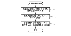
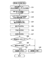
例えば、データ処理部Ksは、電池システムAの製造時に、結線緩みを検出するための基準データを取得する第1採取動作を実行する。つまり、データ処理部Ksにおいて、演算処理部Mcは、二次電池ユニットU1,U2,U3の充電率のパターンと充電電流及び放電電流のパターンとの組み合わせ毎にデータ(電圧全体値、電圧合計値及び電流全体値)を取得する。 For example, when the battery system A is manufactured, the data processing unit Ks executes a first collecting operation of acquiring reference data for detecting loose connections. That is, in the data processing unit Ks, the arithmetic processing unit Mc sets data (total voltage value, total voltage value) for each combination of the charging rate pattern of the secondary battery units U1, U2, and U3 and the charging current and discharging current patterns. And the overall current value).
なお、上記電圧全体値は、電池システムAのシステム全体の出力電圧、すなわち、電圧検出信号によって示される電圧である。また、上記電圧合計値とは、セル電圧データによって示される電池セルb11〜b13,b21〜b23,b31〜b33各々の電圧値を合計した値である。また、上記電流全体値は、電池システムAのシステム全体の出力電流、つまり電流検出信号によって示される電流である。なお、電圧合計値は、セル電圧データに基づいて演算処理部Mcにより算出される。 The total voltage value is the output voltage of the entire battery system A, that is, the voltage indicated by the voltage detection signal. Moreover, the said voltage total value is the value which totaled the voltage value of each battery cell b11-b13, b21-b23, b31-b33 shown by cell voltage data. The total current value is an output current of the entire battery system A, that is, a current indicated by the current detection signal. The total voltage value is calculated by the arithmetic processing unit Mc based on the cell voltage data.
例えば、作業者は、上述した充電率のパターンとして、二次電池ユニットU1,U2,U3の充電率を調整して95%、50%及び5%の3パターンに切り替えると共に、充電率のパターン毎に、放電電流のパターンとして、最大放電電流の10%、20%、30%、40%、50%、60%、70%、80%、90%、100%の10パターンに切り替えて放電させる。つまり、作業者は、各パターンを組み合わせた30通りの二次電池ユニットU1,U2,U3の動作状態を、各種操作によって作り出す。 For example, the worker adjusts the charging rates of the secondary battery units U1, U2, and U3 to switch to three patterns of 95%, 50%, and 5% as the charging rate patterns described above, and each charging rate pattern 10 patterns of 10%, 20%, 30%, 40%, 50%, 60%, 70%, 80%, 90%, 100% of the maximum discharge current are switched and discharged as a pattern of discharge current. That is, the worker creates the operation states of the 30 secondary battery units U1, U2, and U3 in which the patterns are combined by various operations.
また、作業者は、充電率を調整して95%、50%及び5%の3パターンに切り替えると共に、充電率のパターン毎に、充電電流として最大充電電流の10%、20%、30%、40%、50%、60%、70%、80%、90%、100%の10パターンに切り替えて充電させる。つまり、作業者は、さらに30通りの二次電池ユニットU1,U2,U3の動作状態を、各種操作によって作り出す(ステップS1)。 In addition, the operator adjusts the charge rate and switches to three patterns of 95%, 50% and 5%, and 10%, 20%, 30% of the maximum charge current as the charge current for each charge rate pattern. Switch to 10 patterns of 40%, 50%, 60%, 70%, 80%, 90% and 100% to charge. That is, the worker creates the operation states of the 30 secondary battery units U1, U2, and U3 by various operations (step S1).
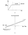
演算処理部Mcは、上述した合計60通りの組み合わせ毎に、電圧全体値、電圧合計値及び電流全体値を取得する。ここで、演算処理部Mcは、電圧全体値、電圧合計値及び電流全体値を取得する際に、電流検出信号によって示される電流全体値を監視する。そして、演算処理部Mcは、電流全体値が安定した状態になってから、電圧全体値、電圧合計値及び電流全体値を取得する。例えば、演算処理部Mcは、充電時、図3(a)に示すように電流全体値が変化し、図3(a)に示す安定状態となってから電流全体値を取得する(ステップS2)。 The arithmetic processing unit Mc acquires the total voltage value, the total voltage value, and the total current value for each of the total of 60 combinations described above. Here, when acquiring the total voltage value, the total voltage value, and the total current value, the arithmetic processing unit Mc monitors the total current value indicated by the current detection signal. Then, the arithmetic processing unit Mc acquires the overall voltage value, the total voltage value, and the overall current value after the overall current value has become stable. For example, at the time of charging, the arithmetic processing unit Mc changes the overall current value as shown in FIG. 3A and acquires the overall current value after the stable state shown in FIG. 3A (step S2). .
演算処理部Mcは、電流全体値の変化率が変化率しきい値よりも小さくなる、あるいは電流全体値の電流値が電流しきい値よりも高くなった場合に、電流全体値が安定状態になったと判断する。なお、演算処理部Mcは、電流全体値の変化率と電流全体値の電流値との両方の条件が満たされた場合に、電流全体値が安定状態になったと判断するようにしてもよい。そして、演算処理部Mcは、電流全体値が安定状態になると、その後、電流全体値に加え、電圧全体値及び電圧合計値を取得する。 If the rate of change of the overall current value becomes smaller than the rate of change threshold or the current value of the overall current value becomes higher than the current threshold, the arithmetic processing unit Mc makes the overall current value stable. I judge that it became. The arithmetic processing unit Mc may determine that the overall current value has become stable when the conditions for both the change rate of the overall current value and the current value of the overall current value are satisfied. Then, when the entire current value is in a stable state, the arithmetic processing unit Mc then acquires the entire voltage value and the total voltage value in addition to the entire current value.
また、演算処理部Mcは、作業者からの取得指示に基づいて電流全体値が安定状態になったとして、電流全体値、電圧全体値及び電圧合計値を取得するようにしてもよい。例えば、充電時、電流全体値は、放電開始から約1秒程度で安定状態となる。作業者は、電流全体値が安定状態になると、演算処理部Mcに取得指示を入力する。演算処理部Mcは、取得指示が入力されると、電流全体値、電圧全体値及び電圧合計値を取得する。なお、作業者からの取得指示は、所定の操作部あるいは、通信を介して演算処理部Mcに入力するようにすればよい。これにより、演算処理部Mcは、電流全体値の変化率が変化率しきい値よりも大きい、あるいは電流全体値の電流値が電流しきい値よりも小さい期間における電流全体値、電圧全体値及び電圧合計値を取得できる。 Further, the arithmetic processing unit Mc may acquire the entire current value, the entire voltage value, and the total voltage value on the assumption that the entire current value has become stable based on an acquisition instruction from the operator. For example, at the time of charging, the entire current value becomes stable in about one second from the start of discharge. The operator inputs an acquisition instruction to the arithmetic processing unit Mc when the entire current value becomes stable. When the acquisition instruction is input, the arithmetic processing unit Mc acquires a total current value, a total voltage value, and a total voltage value. The acquisition instruction from the worker may be input to the arithmetic processing unit Mc via a predetermined operation unit or communication. Thereby, the arithmetic processing unit Mc calculates the total current value, the total voltage value, and the total current value in a period in which the change rate of the total current value is larger than the change rate threshold or the current value of the total current value is smaller You can get the total voltage value.
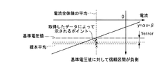
そして、演算処理部Mcは、上述した合計60通りの組み合わせに応じて取得した電圧全体値、電圧合計値及び電流全体値に基づいて線形回帰直線「y=αx+β」(図3(b)参照)を求める(ステップS3)。この線形回帰直線「y=αx+β」の「x」は「電流全体値」である。また、「y」は、「電圧合計値−電圧全体値」である。また、「α」(傾き)は、結線緩み等によって生じる接触抵抗や、バスバーBs1〜Bs4の線路抵抗を示す値である。また、「β」(切片)は、電圧センサDやセル電圧計測部Sk1による測定誤差を示す値である。演算処理部Mcは、上記線形回帰直線「y=αx+β」を基準データとして記憶する。演算処理部Mcは、上記ステップS1〜S3の処理を実行して、第1採取動作を完了する。 Then, the arithmetic processing unit Mc calculates a linear regression line “y = αx + β” based on the total voltage value, the total voltage value, and the total current value acquired according to the total of 60 combinations described above (see FIG. 3B). Are determined (step S3). “X” of this linear regression line “y = αx + β” is “total current value”. Also, "y" is "total voltage value-total voltage value". “Α” (inclination) is a value indicating the contact resistance caused by loose connection or the like, or the line resistance of the bus bars Bs1 to Bs4. Further, “β” (intercept) is a value indicating a measurement error by the voltage sensor D or the cell voltage measurement unit Sk1. The arithmetic processing unit Mc stores the linear regression line “y = αx + β” as reference data. The arithmetic processing unit Mc executes the processes of steps S1 to S3 and completes the first collecting operation.
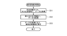
また、データ処理部Ksは、実際に運航される船舶に電池システムAが搭載され、電池セルb11〜b13,b21〜b23,b31〜b33の取り替え等によって、ボルトの取り外し及び締め直しを行った後に、基準データを取り直す第2採取動作を実行する。つまり、演算処理部Mcは、船舶の運航時に、所定の操作部に第2データ採取指示が入力されると、所定回数、データ(電圧全体値、電圧合計値及び電流全体値)を取得する。なお、船舶の運航時には、動作に応じて二次電池ユニットU1,U2,U3の放電及び充電が行われている。 In the data processing unit Ks, after the battery system A is mounted on the vessel actually operated and the bolts are removed and retightened by replacing the battery cells b11 to b13, b21 to b23, b31 to b33, etc. , The second sampling operation of retaking the reference data is executed. That is, when the second data acquisition instruction is input to the predetermined operation unit at the time of ship operation, the arithmetic processing unit Mc acquires data (total voltage value, total voltage value, and total current value) a predetermined number of times. During operation of the ship, discharge and charge of the secondary battery units U1, U2, U3 are performed according to the operation.
また、演算処理部Mcは、上記所定回数のうち、半分を、二次電池ユニットU1,U2,U3の放電時にデータを取得し(ステップS11)、一方残り半分を、充電時にデータを取得する(ステップS12)。したがって、上記所定回数は、偶数であることが望ましい。演算処理部Mcは、例えば、所定回数が100回である場合、放電時に50回データを取得し、一方、充電時に50回データを取得する。 In addition, the arithmetic processing unit Mc acquires half of the predetermined number of times when discharging the secondary battery units U1, U2, U3 (step S11), and acquires the other half when charging the data (when charging) (step S11) Step S12). Therefore, the predetermined number of times is preferably an even number. For example, when the predetermined number of times is 100, the arithmetic processing unit Mc acquires data 50 times during discharge, and acquires data 50 times during charge.
ここで、演算処理部Mcは、電圧全体値、電圧合計値及び電流全体値を取得する際に、第1採取動作のステップS2の処理同様、電流検出信号によって示される電流全体値を監視する。つまり、演算処理部Mcは、第1採取動作同様、電流全体値が安定した状態になってから、電圧全体値、電圧合計値及び電流全体値を取得する。 Here, when acquiring the overall voltage value, the total voltage value, and the overall current value, the arithmetic processing unit Mc monitors the overall current value indicated by the current detection signal as in the process of step S2 of the first sampling operation. That is, as in the first sampling operation, the arithmetic processing unit Mc acquires the overall voltage value, the total voltage value, and the overall current value after the overall current value has become stable.
そして、演算処理部Mcは、所定回数、データを取得すると、第1採取動作同様、取得したデータである電圧全体値、電圧合計値及び電流全体値に基づいて線形回帰直線「y=αx+β」を求める(ステップS13)。演算処理部Mcは、上記線形回帰直線「y=αx+β」を基準データとして記憶する。演算処理部Mcは、上記ステップS11〜S13の処理を実行して、第2採取動作を完了する。 Then, when the arithmetic processing unit Mc acquires data a predetermined number of times, as in the first sampling operation, the linear regression line “y = αx + β” is obtained based on the acquired voltage total value, voltage total value, and current total value as acquired data. It asks for (Step S13). The arithmetic processing unit Mc stores the linear regression line “y = αx + β” as reference data. The arithmetic processing unit Mc executes the processes of steps S11 to S13 and completes the second collecting operation.
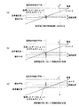
また、データ処理部Ksは、上記基準データを使用して、結線緩みを判定する第1緩み判定動作を実行する。例えば、演算処理部Mcは、船舶の運航時に、定期的に、上記第1緩み判定動作を実行する。まず、演算処理部Mcは、充電時、所定回数、結線緩みを判定するためのデータ(電圧全体値、電圧合計値及び電流全体値)を取得する(ステップS21)。ここで、演算処理部Mcは、1回の充電動作の間に、所定回数、データ(電圧全体値、電圧合計値及び電流全体値)を取得する。したがって、取得された電圧全体値、電圧合計値及び電流全体値各々は、近似した値となる。そのため、データによって示されるポイントは、図6(a)に示すように、かたまっている。 In addition, the data processing unit Ks executes a first looseness determination operation that determines loose connections using the reference data. For example, the arithmetic processing unit Mc periodically executes the first slack determination operation at the time of ship operation. First, the arithmetic processing unit Mc acquires data (entire voltage value, total voltage value, and total current value) for determining loose connections a predetermined number of times during charging (step S21). Here, the arithmetic processing unit Mc acquires data (total voltage value, total voltage value, and total current value) a predetermined number of times during one charging operation. Therefore, each of the acquired voltage overall value, voltage total value, and current overall value is an approximate value. Therefore, the points indicated by the data are concentrated as shown in FIG. 6 (a).
また、演算処理部Mcは、電圧全体値、電圧合計値及び電流全体値を取得する際に、第1採取動作同様、電流検出信号によって示される電流全体値を監視する。つまり、演算処理部Mcは、第1採取動作同様、電流全体値が安定した状態になってから、電圧全体値、電圧合計値及び電流全体値を取得する。 Further, when acquiring the total voltage value, the total voltage value, and the total current value, the arithmetic processing unit Mc monitors the total current value indicated by the current detection signal as in the first sampling operation. That is, as in the first sampling operation, the arithmetic processing unit Mc acquires the overall voltage value, the total voltage value, and the overall current value after the overall current value has become stable.
続いて、演算処理部Mcは、所定回数、データの取得が完了すると、下記式(1)に基づいて各取得データの「電圧合計値−電圧全体値」を標本とする標本平均Vavgを算出する(ステップS22)。なお、下記式(1)の値「n」は、データの個数、つまり、上記所定回数と同じ値になる。
Vavg = Σ(電圧合計値−電圧全体値)/n (1)
そして、演算処理部Mcは、下記式(2)に上記標本平均Vavgを代入して不偏分散S^2を算出する(ステップS23)。
S^2=Σ{(電圧合計値−電圧全体値)−Vavg)}^2/(n−1) (2)
Subsequently, when acquisition of data is completed a predetermined number of times, the arithmetic processing unit Mc calculates a sample average Vavg taking “voltage total value−total voltage value” of each acquired data as a specimen based on the following equation (1) (Step S22). The value “n” of the following equation (1) is the same as the number of data, that is, the predetermined number of times.
Vavg = ((total voltage value-total voltage value) / n (1)
Then, the arithmetic processing unit Mc substitutes the sample average Vavg into the following equation (2) to calculate the unbiased variance S ^ 2 (step S23).
S ^ 2 = {{(total voltage value-total voltage value)-Vavg)} ^ 2 / (n-1) (2)
そして、演算処理部Mcは、標本平均Vavg及び不偏分散S^2に基づいて下記式(3)に示す信頼区間、つまり上記標本を含む母集団の母平均の信頼区間を求める。(ステップS24)。
Vavg−k×S^2/√n≦母平均≦Vavg+k×S^2/√n (3)
なお、第1緩み判定動作では、標本の数が少ない、つまり、取得したデータの数が少ないため、上記変数「k」を信頼度(95%や99%等)に基づいてt分布から決定する。
Then, the arithmetic processing unit Mc obtains a confidence interval shown in the following equation (3) based on the sample average Vavg and the unbiased variance S ^ 2, that is, a confidence interval of the population mean of the population including the sample. (Step S24).
Vavg-k x S ^ 2 / ≦ n 母 population average Va Vavg + k x S ^ 2 / n n (3)
In the first looseness determination operation, since the number of samples is small, that is, the number of acquired data is small, the variable “k” is determined from the t distribution based on the reliability (95%, 99%, etc.) .
続いて、演算処理部Mcは、基準データ「y=αx+β」の「x」に、上記ステップS21の処理で取得した電流全体値の平均値を代入して「y」の値である基準電圧値を取得する。そして、演算処理部Mcは、基準電圧値が上記信頼区間に含まれるか否か判断する(ステップS25)。演算処理部Mcは、基準電圧値が信頼区間に含まれる場合(YESの場合)、結線緩み無しと判断する(ステップS26)。一方、演算処理部Mcは、基準電圧値が信頼区間に含まれない場合(NOの場合)、基準電圧値に対して信頼区間が負側に存在するか否か判定する(ステップS27)。 Subsequently, the arithmetic processing unit Mc substitutes the average value of the entire current values acquired in the process of step S21 into “x” of the reference data “y = αx + β” to obtain a reference voltage value which is a value of “y”. To get Then, the arithmetic processing unit Mc determines whether or not the reference voltage value is included in the confidence interval (step S25). If the reference voltage value is included in the confidence interval (in the case of YES), the arithmetic processing unit Mc determines that there is no loose connection (step S26). On the other hand, when the reference voltage value is not included in the confidence section (in the case of NO), the arithmetic processing unit Mc determines whether the confidence section exists on the negative side with respect to the reference voltage value (step S27).
基準電圧値に対して信頼区間が負側に存在する(図6(b)参照)ということは、結線緩み等による接触抵抗が増加して、電圧全体値が大きくなっていることを示している。つまり、演算処理部Mcは、電圧全体値が結線緩み等によって大きくなることで、基準電圧値に対して信頼区間が負側に存在するか否か判定している。演算処理部Mcは、基準電圧値に対して信頼区間が負側に存在する場合(YESの場合)、結線緩みが有ると判断する(ステップS28)。 The fact that the confidence interval exists on the negative side with respect to the reference voltage value (see FIG. 6 (b)) indicates that the contact resistance due to loose connections etc. increases and the overall voltage value increases. . That is, the calculation processing unit Mc determines whether the confidence interval exists on the negative side with respect to the reference voltage value by the entire voltage value becoming large due to loose connection or the like. If the confidence interval is on the negative side with respect to the reference voltage value (in the case of YES), the arithmetic processing unit Mc determines that there is loose connection (step S28).
一方、演算処理部Mcは、基準電圧値に対して信頼区間が負側に存在しない場合(NOの場合)、上記ステップS26の処理において、結線緩み無しと判断する。そして、演算処理部Mcは、結線緩みの有りあるいは無しの判断結果を、外部の監視装置やデータ記憶装置等に出力する。演算処理部Mcは、上記ステップS21〜S28の処理を実行して、第1緩み判定動作を完了する。 On the other hand, when the confidence interval does not exist on the negative side with respect to the reference voltage value (in the case of NO), the arithmetic processing unit Mc determines that there is no loose connection in the process of step S26. Then, the arithmetic processing unit Mc outputs the determination result of presence or absence of loose connection to an external monitoring device, a data storage device, or the like. The arithmetic processing unit Mc executes the processes of steps S21 to S28 to complete the first looseness determination operation.
また、上記第1緩み判定動作では、上記ステップS21の処理において、充電時にデータを取得しているが、充電時ではなく、放電時に、データを取得するようにしてもよい。その場合、演算処理部Mcは、上記ステップS27の処理において、基準電圧値に対して信頼区間が正側に存在するか否か判定し、基準電圧値に対して信頼区間が正側に存在する場合(図6(c)参照)、上記ステップS28の処理において、結線緩みが有ると判断する。 In the first looseness determination operation, data is acquired at the time of charging in the process of step S21. However, data may be acquired at the time of discharging instead of charging. In that case, the arithmetic processing unit Mc determines whether or not the confidence interval exists on the positive side with respect to the reference voltage value in the process of step S27, and the confidence interval exists on the positive side with respect to the reference voltage value. In the case (see FIG. 6C), it is determined in the process of step S28 that there is loose connection.
また、電池セルb11〜b13,b21〜b23,b31〜b33の取り替え等によって、ボルトの取り外し及び締め直しを行った後に、基準データを取り直す第2採取動作を実行する前に、例えば、上記第1緩み判定動作を行うことで、ボルトの締め直し判定を行うようにしてもよい。その際、結線緩み等があったとしても発火のおそれのない低い電流を充電あるいは放電して、上記第1緩み判定動作を行うことで、結線緩みを判断するようにしてもよい。 In addition, after removing and retightening the bolts by replacing the battery cells b11 to b13, b21 to b23, b31 to b33, etc., before performing the second collecting operation for reading the reference data, for example, The bolt retightening determination may be performed by performing the looseness determination operation. At this time, the loose connection may be determined by charging or discharging a low current that does not have a possibility of ignition even if there is loose connection etc. and performing the first looseness determination operation.
さらに、上記第1緩み判定動作では、基準電圧に対して信頼区間が負側に存在するか否かに基づいて結線緩みの有り無しを判定しているが、他の方法によって判断するようにしてもよい。例えば、演算処理部Mcは、下記式(11)に基づいて結線緩みの有り無しを判定するようにしてもよい。
Vavg≦基準電圧値−Verror (11)
Furthermore, in the first looseness determination operation described above, the presence or absence of loose connection is determined based on whether or not the confidence interval exists on the negative side with respect to the reference voltage. It is also good. For example, the arithmetic processing unit Mc may determine whether or not the connection is loose based on the following equation (11).
Vavg ≦ reference voltage value − Verror (11)
上記Verrorは、予め実施された試験等に基づいて求められた値である。つまり、演算処理部Mcは、「Vavg(標本平均)」が「基準電圧値−Verror」以下であるか否か判定する。「Vavg」が「基準電圧値−Verror」以下である(図7参照)ということは、結線緩み等による接触抵抗が増加して、電圧全体値が大きくなっていることを示している。つまり、演算処理部Mcは、電圧全体値が、結線緩み等によって大きくなることで、「Vavg」が「基準電圧値−Verror」以下となっているか否か判定している。演算処理部Mcは、「Vavg」が「基準電圧値−Verror」以下である場合、結線緩みが有ると判断する。一方、演算処理部Mcは、「Vavg」が「基準電圧値−Verror」以下でない場合、結線緩みが無いと判断する。また、充電時ではなく、放電時に、データを取得する場合、下記式(12)に基づいて結線緩みの有り無しを判定するようにしてもよい。
Vavg≧基準電圧値+Verror (12)
つまり、演算処理部Mcは、「Vavg」が「基準電圧値+Verror」以上である場合、結線緩みが有ると判断する。
The above-mentioned Verror is a value obtained based on a test performed beforehand. That is, the arithmetic processing unit Mc determines whether "Vavg (sample average)" is equal to or less than "reference voltage value-Verror". The fact that "Vavg" is less than or equal to "reference voltage value-Verror" (see FIG. 7) indicates that the contact resistance due to loose connections etc. is increased, and the overall voltage value is increased. That is, the arithmetic processing unit Mc determines whether "Vavg" is equal to or less than "reference voltage value-Verror" by the whole voltage value becoming large due to loose connection or the like. If "Vavg" is equal to or less than "reference voltage value-Verror", the arithmetic processing unit Mc determines that there is loose connection. On the other hand, when “Vavg” is not “reference voltage value−Verror” or less, the arithmetic processing unit Mc determines that there is no loose connection. In addition, when data is acquired at the time of discharge, not at the time of charge, the presence or absence of loose connection may be determined based on the following equation (12).
Vavg 基準 reference voltage + Verror (12)
That is, when “Vavg” is “reference voltage value + Verror” or more, the arithmetic processing unit Mc determines that there is loose connection.
また、データ処理部Ksは、第1緩み判定動作に代わって、第1緩み判定動作と異なる第2緩み判定動作を実行するようにしてもよい。例えば、演算処理部Mcは、船舶の運航時に、定期的に、上記第2緩み判定動作を実行する。 Further, the data processing unit Ks may execute a second looseness determination operation different from the first looseness determination operation, instead of the first looseness determination operation. For example, the arithmetic processing unit Mc periodically executes the second slack determination operation at the time of ship operation.
まず、演算処理部Mcは、船舶の運航時に、所定回数、結線緩みを判定するためのデータ(電圧全体値、電圧合計値及び電流全体値)を取得する。なお、船舶の運航時には、動作に応じて二次電池ユニットU1,U2,U3の放電及び充電が行われている。 First, the arithmetic processing unit Mc acquires data (total voltage value, total voltage value, and total current value) for determining loose connections a predetermined number of times at the time of ship operation. During operation of the ship, discharge and charge of the secondary battery units U1, U2, U3 are performed according to the operation.
また、演算処理部Mcは、上記所定回数のうち、半分を、二次電池ユニットU1,U2,U3の放電時にデータを取得し(ステップS31)、一方残り半分を、充電時にデータを取得する(ステップS32)。したがって、上記所定回数は、偶数であることが望ましい。演算処理部Mcは、例えば、所定回数が100回である場合、放電時に50回データを取得し、一方、充電時に50回データを取得する。 Further, the arithmetic processing unit Mc acquires half of the predetermined number of times when discharging the secondary battery units U1, U2, U3 (step S31), and acquires the other half when charging the data (when charging) (step S31) Step S32). Therefore, the predetermined number of times is preferably an even number. For example, when the predetermined number of times is 100, the arithmetic processing unit Mc acquires data 50 times during discharge, and acquires data 50 times during charge.
ここで、演算処理部Mcは、電圧全体値、電圧合計値及び電流全体値を取得する際に、第1採取動作のステップS2の処理同様、電流検出信号によって示される電流全体値を監視する。つまり、演算処理部Mcは、第1採取動作同様、電流全体値が安定した状態になってから、電圧全体値、電圧合計値及び電流全体値を取得する。そして、演算処理部Mcは、上記ステップS31及びステップS32の処理を所定の複数回繰り返す(ステップS33)。つまり、演算処理部Mcは、上記ステップS31〜S33の処理によって、所定回数、データを取得する動作を、所定の複数回繰り返す。 Here, when acquiring the overall voltage value, the total voltage value, and the overall current value, the arithmetic processing unit Mc monitors the overall current value indicated by the current detection signal as in the process of step S2 of the first sampling operation. That is, as in the first sampling operation, the arithmetic processing unit Mc acquires the overall voltage value, the total voltage value, and the overall current value after the overall current value has become stable. Then, the arithmetic processing unit Mc repeats the process of the step S31 and the step S32 a predetermined number of times (step S33). That is, the processing unit Mc repeats the operation of acquiring data a predetermined number of times a predetermined number of times by the processes of steps S31 to S33.
続いて、演算処理部Mcは、上記ステップS31及びステップS32の処理を所定の複数回繰り返してデータの取得が完了すると、下記式(21)に基づいて各取得データから線形回帰直線「y=Cx+E」を求め、該線形回帰直線からボルトの緩み等が原因の接触抵抗を示す傾き「C」を取得する(ステップS34)。つまり、上記線形回帰直線「y=Cx+E」は、上記ステップS31及びステップS32の処理を繰り返した回数分だけ線形回帰直線「y=Cx+E」を取得するので、回数分の傾き「C」を取得できる。
そして、演算処理部Mcは、下記式(21)に基づいて「C」を標本とする標本平均Cavgを算出する(ステップS35)。なお、下記式(21)の値「m」は、データの個数、つまり、上記所定回数と同じ値になる。
Cavg = ΣC/m (21)
そして、演算処理部Mcは、下記式(22)に上記標本平均Cavgを代入して不偏分散S^2を算出する(ステップS36)。
S^2=Σ{(C−Cavg)}^2/(m−1) (22)
Subsequently, when the arithmetic processing unit Mc repeats the processes of steps S31 and S32 a predetermined number of times and data acquisition is completed, a linear regression line “y = Cx + E is obtained from each acquired data based on the following equation (21). Is obtained from the linear regression line, and a slope "C" indicating contact resistance caused by loose bolt etc. is obtained (step S34). That is, since the linear regression line "y = Cx + E" is acquired by the number of times of repeating the process of the step S31 and the step S32, the linear regression line of "y = Cx + E" can be acquired. .
Then, the arithmetic processing unit Mc calculates a sample average Cavg in which "C" is a sample based on the following equation (21) (step S35). The value “m” in the following equation (21) is the same as the number of data, that is, the predetermined number of times.
Cavg = CC / m (21)
Then, the arithmetic processing unit Mc substitutes the sample average Cavg into the following equation (22) to calculate the unbiased variance S ^ 2 (step S36).
S ^ 2 = Σ {(C-Cavg)} ^ 2 / (m-1) (22)
そして、演算処理部Mcは、標本平均Cavg及び不偏分散S^2に基づいて下記式(23)に示す上記標本を含む母集団の母平均の信頼区間を求める。(ステップS37)。
Cavg−k×S^2/√m≦母平均≦Cavg+k×S^2/√m (22)
なお、第2緩み判定動作では、標本の数が少ない、つまり、取得したデータの数が少ないため、上記変数「k」を信頼度(95%や99%等)に基づいてt分布から決定する。
Then, the arithmetic processing unit Mc obtains the confidence interval of the population mean of the population including the above-mentioned sample shown in the following equation (23) based on the sample average Cavg and the unbiased variance S ^ 2. (Step S37).
Cavg−k × S ^ 2 / √m ≦ population average ≦ Cavg + k × S ^ 2 / √m (22)
In the second looseness determination operation, since the number of samples is small, that is, the number of acquired data is small, the variable “k” is determined from the t distribution based on the reliability (95%, 99%, etc.) .
続いて、演算処理部Mcは、基準データ「y=αx+β」の傾き「α」(すなわち基準データの接触抵抗)が上記信頼区間に含まれるか否か判断する(ステップS38)。演算処理部Mcは、傾き「α」が信頼区間に含まれる場合(YESの場合)、結線緩み無しと判断する(ステップS39)。一方、演算処理部Mcは、傾き「α」が信頼区間に含まれない場合(NOの場合)、傾き「α」に対して信頼区間が大きい側に存在するか否か判定する(ステップS40)。 Subsequently, the arithmetic processing unit Mc determines whether the inclination “α” of the reference data “y = αx + β” (that is, the contact resistance of the reference data) is included in the above-mentioned confidence interval (step S38). If the inclination “α” is included in the confidence section (in the case of YES), the arithmetic processing unit Mc determines that there is no loose connection (step S39). On the other hand, when the inclination “α” is not included in the confidence section (in the case of NO), the arithmetic processing unit Mc determines whether or not the confidence section is larger than the inclination “α” (step S40). .
傾き「α」に対して信頼区間が大きい側に存在するということは、結線緩み等による接触抵抗が増加していることを示している。つまり、演算処理部Mcは、接触抵抗が増加することで、傾き「α」に対して信頼区間が大きい側に存在するか否か判定する。演算処理部Mcは、傾き「α」に対して信頼区間が大きい側に存在する場合には、結線緩み有りと判断する(ステップS41)。 The fact that the confidence interval is larger with respect to the inclination “α” indicates that the contact resistance due to loose connection or the like is increased. That is, as the contact resistance increases, the arithmetic processing unit Mc determines whether the confidence interval is present on the larger side with respect to the inclination “α”. The arithmetic processing unit Mc determines that the connection is loosened when the confidence interval is larger than the inclination “α” (step S41).
一方、演算処理部Mcは、「α」に対して信頼区間が大きい側に存在しない場合には、結線緩み無しと判断する。そして、演算処理部Mcは、結線緩みの有りあるいは無しの判断結果を、外部の監視装置やデータ記憶装置等に出力する。演算処理部Mcは、上記ステップS31〜S41の処理を実行して、第2緩み判定動作を完了する。 On the other hand, when the confidence interval does not exist on the side where the confidence interval is larger than “α”, the computation processing unit Mc determines that the connection is not loosened. Then, the arithmetic processing unit Mc outputs the determination result of presence or absence of loose connection to an external monitoring device, a data storage device, or the like. Arithmetic processing unit Mc executes the processes of steps S31 to S41 and completes the second looseness determination operation.
また、電池セルb11〜b13,b21〜b23,b31〜b33の取り替え等によって、ボルトの取り外し及び締め直しを行った後に、基準データを取り直す第2採取動作を実行する前に、例えば、上記第2緩み判定動作を行うことで、ボルトの締め直し判定を行うようにしてもよい。その際、結線緩み等があったとしても発火のおそれのない低い電流を充電あるいは放電して、上記第2緩み判定動作を行うことで、結線緩みを判断するようにしてもよい。 In addition, after removing and retightening the bolts by replacing the battery cells b11 to b13, b21 to b23, b31 to b33, etc., for example, before performing the second collecting operation for recollecting the reference data, for example, The bolt retightening determination may be performed by performing the looseness determination operation. At this time, the loose connection may be determined by charging or discharging a low current that does not have a possibility of ignition even if there is loose connection etc. and performing the second looseness determination operation.
さらに、上記第2緩み判定動作では、傾き「α」に対して信頼区間が大きい側に存在するか否かに基づいて結線緩みの有り無しを判定しているが、他の方法によって判断するようにしてもよい。例えば、演算処理部Mcは、下記式(31)に基づいて結線緩みの有り無しを判定するようにしてもよい。
Cavg≧Cerror (31)
Furthermore, in the second looseness determination operation described above, the presence or absence of loose connection is determined based on whether or not the confidence interval is on the larger side with respect to the inclination “α”. You may For example, the arithmetic processing unit Mc may determine presence or absence of connection looseness based on the following equation (31).
Cavg C Cerror (31)
上記Cerrorは、予め実施された試験等に基づいて求められた値である。つまり、演算処理部Mcは、「Cavg(標本平均)」が「Cerror」以上であるか否か判定する。「Cavg」が「Cerror」以上であるということは、結線緩み等による接触抵抗が増加していることを示している。つまり、演算処理部Mcは、結線緩み等によって接触抵抗が大きくなることで、「Cavg」が「Cerror」以上となっているか否か判定している。 The above-mentioned Cerror is a value obtained based on a test performed beforehand. That is, the arithmetic processing unit Mc determines whether "Cavg (sample average)" is equal to or more than "Cerror". The fact that "Cavg" is greater than "Cerror" indicates that the contact resistance due to loose connections etc. is increased. That is, the arithmetic processing unit Mc determines whether “Cavg” is equal to or more than “Cerror” by the increase in the contact resistance due to loose connection or the like.
演算処理部Mcは、「Cavg」が「Cerror」以上である場合、結線緩みが有ると判断する。一方、演算処理部Mcは、「Cavg」が「Cerror」以下でない場合、結線緩みが無いと判断する。また、所定の複数回、ステップS31,S32の処理を繰り返してデータを取得し、このデータに基づいて「Cavg(標本平均)」を求めているが、1回の上記ステップS31及びステップS32の処理で得られるデータの線形回帰直線「y=Cx+E」の傾き「C」と「Cerror」とを比較して、結線緩みの有り無しを判断するようにしてもよい。 If “Cavg” is “Cerror” or more, the arithmetic processing unit Mc determines that there is a loose connection. On the other hand, when “Cavg” is not “Cerror” or less, the arithmetic processing unit Mc determines that there is no loose connection. Also, although the processing of steps S31 and S32 is repeated a predetermined number of times to acquire data, and "Cavg (sample average)" is obtained based on this data, one processing of the above steps S31 and S32 is performed. The slope “C” of the linear regression line “y = Cx + E” of the data obtained in the above may be compared with “Cerror” to determine the presence or absence of loose connections.
このような本実施形態によれば、演算処理部Mcは、電圧センサD、電流センサY及びセル電圧計測部Sk1,Sk2,Sk3の計測値(電圧全体値、電流全体値及びセル電圧)のうち、所定の電流しきい値よりも小さい電流が計測される期間における電圧全体値、電流全体値及びセル電圧を除外する、つまり、電流全体値が安定した状態になってから、電圧全体値、電圧合計値及び電流全体値を取得し、線形回帰直線を求める(つまり接触抵抗を求める)ので、電池システムAにおける接触抵抗を従来よりも正確に評価することが可能である。 According to the present embodiment, the arithmetic processing unit Mc is a part of the measurement values (total voltage value, total current value, and cell voltage) of the voltage sensor D, the current sensor Y, and the cell voltage measurement units Sk1, Sk2, and Sk3. Excluding the total voltage value, the total current value, and the cell voltage during a period when a current smaller than a predetermined current threshold is measured, that is, after the total current value becomes stable, the total voltage value, voltage Since the total value and the overall current value are obtained and the linear regression line is determined (that is, the contact resistance is determined), the contact resistance in the battery system A can be evaluated more accurately than in the past.
すなわち、電流しきい値よりも小さい電流が計測される期間における電圧全体値、電流全体値及びセル電圧は各々に値が小さいため、セル電圧計測部Sk1,Sk2,Sk3から演算処理部Mcまでのデータの伝送時間と、電圧センサD及び電流センサYら演算処理部Mcまでの伝送時間との間にずれが生じた場合に、接触抵抗の判定に与える影響が電流が上記電流しきい値よりも大きい場合よりも大きい。また、電流しきい値よりも小さい電流が計測される期間における電圧全体値、電流全体値及びセル電圧は各々に値が小さいため、計測誤差の影響も大きい。 That is, since the whole voltage value, the whole current value, and the cell voltage in the period in which the current smaller than the current threshold is measured are respectively smaller, the values from cell voltage measuring units Sk1, Sk2, Sk3 to operation processing unit Mc If a shift occurs between the data transmission time and the transmission time to the voltage sensor D and the current sensor Y, etc., the influence of the current on the determination of the contact resistance is higher than the current threshold. Larger than large. In addition, since the overall voltage value, the overall current value, and the cell voltage in a period in which a current smaller than the current threshold is measured are respectively small, the influence of the measurement error is large.
したがって、本実施形態によれば、電流の大小に依らず全ての計測値を用いて接触抵抗を演算する従来技術に比較して、電池システムAにおける接触抵抗を正確に評価することが可能である。 Therefore, according to the present embodiment, it is possible to accurately evaluate the contact resistance in the battery system A, as compared with the prior art in which the contact resistance is calculated using all the measured values regardless of the magnitude of the current. .
以上、本発明の実施形態について説明したが、本発明は上記実施形態に限定されることなく、例えば以下のような変形が考えられる。
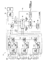
(1)上記実施形態は、図1に示す構成となっているが、本発明はこれに限定されない。例えば、図9に示すように、線路電圧計測部Rk1,Rk2,Rk3,Rk4を備えるようにしてもよい。線路電圧計測部Rk1,Rk2,Rk3,Rk4は、バスバーBs1〜Bs4各々のボルト接続部に対して設けられ、電池ユニット端子T11,T12,T21,T22,T31,T32及び電池端子DT1,DT2を介して、バスバーBs1〜Bs4を流れる電力の電圧(つまりバスバーBs1〜Bs4の両端電圧)を検出し、検出結果をデジタル変換し、線路電圧データを通信処理部Ts1,Ts2,Ts3に出力する。通信処理部Ts1,Ts2,Ts3に出力される線路電圧データは、セル電圧データと同様、通信処理部Ts1,Ts2,Ts3を介して、演算処理部Mcに出力される。演算処理部Mcは、ボルト接続部各々における接触抵抗を求め、結線緩みが発生している場所を特定できる。また、図10のように、線路電圧計測部Rk1,Rk2,Rk3,Rk4に代わって、アナログである線路電圧検出信号を出力する線路電圧センサsd1,sd2,sd3,sd4を備えることも考えられる。線路電圧センサsd1,sd2,sd3,sd4は、線路電圧検出信号をアナログ入力部Akに出力する。アナログ入力部Akは、線路電圧検出信号をデジタル変換して、演算処理部Mcに出力する。演算処理部Mcは、ボルト接続部各々における接触抵抗を求め、結線緩みが発生している場所を特定できる。また、上記実施形態では、演算処理部Mcが、電圧検出信号、電流検出信号及びセル電圧データに基づいて上述した第1採取動作、第2採取動作、第1緩み判定動作及び第2緩み判定動作を行っているが、上述した動作を行わず、外部の監視装置やデータ記憶装置等に電圧検出信号、電流検出信号及びセル電圧データを出力し、外部に上述した動作を実行させるようにしてもよい。
As mentioned above, although embodiment of this invention was described, this invention is not limited to the said embodiment, For example, the following deformation | transformation can be considered.
(1) The above embodiment is configured as shown in FIG. 1, but the present invention is not limited to this. For example, as shown in FIG. 9, line voltage measurement units Rk1, Rk2, Rk3 and Rk4 may be provided. Line voltage measurement units Rk1, Rk2, Rk3, Rk4 are provided for the bolt connection portions of bus bars Bs1 to Bs4, respectively, through battery unit terminals T11, T12, T21, T22, T22, T31, T32 and battery terminals DT1, DT2. Thus, the voltage of the power flowing through the bus bars Bs1 to Bs4 (that is, the voltage across the bus bars Bs1 to Bs4) is detected, the detection result is converted to digital, and the line voltage data is output to the communication processing units Ts1, Ts2 and Ts3. The line voltage data output to the communication processing units Ts1, Ts2, and Ts3 are output to the arithmetic processing unit Mc via the communication processing units Ts1, Ts2, and Ts3, as in the cell voltage data. The arithmetic processing unit Mc can determine the contact resistance at each of the bolt connection portions, and can specify the place where the loose connection occurs. Further, as shown in FIG. 10, it is also conceivable to provide line voltage sensors sd1, sd2, sd3, sd4 which output analog line voltage detection signals in place of the line voltage measurement units Rk1, Rk2, Rk3, Rk4. The line voltage sensors sd1, sd2, sd3, sd4 output a line voltage detection signal to the analog input unit Ak. The analog input unit Ak converts the line voltage detection signal into a digital signal, and outputs the digital signal to the arithmetic processing unit Mc. The arithmetic processing unit Mc can determine the contact resistance at each of the bolt connection portions, and can specify the place where the loose connection occurs. In the above embodiment, the arithmetic processing unit Mc performs the first sampling operation, the second sampling operation, the first slack determination operation, and the second slack determination operation described above based on the voltage detection signal, the current detection signal, and the cell voltage data. Although the above operation is not performed, the voltage detection signal, the current detection signal, and the cell voltage data are output to an external monitoring device, a data storage device, etc., and the above operation is performed outside. Good.
(2)上記実施形態では、電池セルb11〜b13,b21〜b23,b31〜b33から構成される二次電池ユニットU1,U2,U3がバスバーBs2,バスバーBs3を介して接続されることで1つの電池を構成し、電池セルb11〜b13,b21〜b23,b31〜b33各々がセル電圧計測部Sk1,Sk2,Sk3によって電圧が計測される構成となっているが、本発明はこれに限定されない。例えば、電力変換器Dcに接続される1つの電池に対して、セル電圧計測部Sk1,Sk2,Sk3を設けない。一方、演算処理部Mcは、電圧センサDからの電圧検出信号によって示される電圧全体値と、電流センサYからの電流検出信号によって示される電圧全体値とに基づいてバスバーBs1やバスバーBs4のボルトの接続部の接触抵抗を算出するようにしてもよい。 (2) In the above embodiment, the secondary battery units U1, U2 and U3 configured of the battery cells b11 to b13, b21 to b23, and b31 to b33 are connected via the bus bar Bs2 and the bus bar Bs3. The battery is configured, and each of the battery cells b11 to b13, b21 to b23, and b31 to b33 has a configuration in which the voltage is measured by the cell voltage measurement units Sk1, Sk2, and Sk3, but the present invention is not limited thereto. For example, the cell voltage measurement units Sk1, Sk2, and Sk3 are not provided for one battery connected to the power converter Dc. On the other hand, based on the overall voltage value indicated by the voltage detection signal from the voltage sensor D and the overall voltage value indicated by the current detection signal from the current sensor Y, the arithmetic processing unit Mc uses the voltage of the bus bar Bs1 or the bus bar Bs4. The contact resistance of the connection may be calculated.
(3)上記実施形態では、電圧全体値、電圧合計値及び電流全体値に基づいて線形回帰直線を求めているが、これは得られるデータ(電圧全体値、電圧合計値及び電流全体値)にばらつきがあるためである。例えば、演算処理部Mcは、電圧全体値、電圧合計値及び電流全体値を、ローパスフィルタ処理することにより、電流しきい値よりも小さく、かつ、変化率しきい値よりも大きい変化率の電流全体値が計測される期間における電圧全体値、電圧合計値及び電流全体値を除外するようにしてもよい。ローパスフィルタ処理によってデータのばらつきが低減されるため、ローパスフィルタ処理を施されたデータをそのまま使用して接触抵抗を求めた場合でも、誤差を小さくすことができる。 (3) In the above embodiment, the linear regression line is obtained based on the entire voltage value, the total voltage value, and the total current value, but this is the data obtained (total voltage value, total voltage value and total current value) It is because there is variation. For example, the arithmetic processing unit Mc performs low-pass filter processing on the entire voltage value, the total voltage value, and the entire current value, so that the current whose change rate is smaller than the current threshold and greater than the change rate threshold The total voltage value, total voltage value, and total current value may be excluded during the period when the total value is measured. Since the variation in data is reduced by the low pass filter processing, the error can be reduced even when the contact resistance is determined using the data subjected to the low pass filter processing as it is.
(4)上記実施形態では、3個の電池モジュールM1〜M3の各々に対して3個の電池セルb11〜b13,b21〜b23,b31〜b33を備える例を挙げたが、電池モジュールや電池セルの個数が限定されることはない。 (4) In the above embodiment, an example in which three battery cells b11 to b13, b21 to b23 and b31 to b33 are provided for each of three battery modules M1 to M3 has been described. The number of is not limited.
A 電池システム
Ak アナログ入力部
b11〜b13 電池セル
b21〜b23 電池セル
b31〜b33 電池セル
Bs1〜Bs4 バスバー(電力伝送部材、第2電力伝送部材)
D 電圧センサ(電圧計測手段)
Dc 電力変換器
Dk デジタル入力部
Ds デジタル出力部
DT1,DT2 電池端子
Ks データ処理部
Ld 負荷
M1,M2,M3 電池モジュール
Mc 演算処理部(接触抵抗演算手段)
Rk1,Rk2,Rk3,Rk4 線路電圧計測部(電圧計測手段)
sd1,sd2,sd3,sd4 線路電圧センサ(電圧計測手段)
Sk1,Sk2,Sk3 セル電圧計測部(電圧計測手段)
T11,T12 電池ユニット端子
T21,T22 電池ユニット端子
T31,T32 電池ユニット端子
Ts1,Ts2,Ts3 通信処理部
U1,U2,U3 二次電池ユニット
Y 電流センサ(電流計測手段)
A Battery system Ak Analog input section b11 to b13 battery cell b21 to b23 battery cell b31 to b33 battery cell Bs1 to Bs4 bus bar (power transmission member, second power transmission member)
D Voltage sensor (voltage measurement means)
Dc Power Converter Dk Digital Input Ds Digital Output DT1, DT2 Battery Terminal Ks Data Processor Ld Load M1, M2, M3 Battery Module Mc Arithmetic Processor (Contact Resistance Calculator)
Rk1, Rk2, Rk3, Rk4 Line voltage measurement unit (voltage measurement means)
sd1, sd2, sd3, sd4 line voltage sensor (voltage measurement means)
Sk1, Sk2, Sk3 Cell voltage measurement unit (voltage measurement means)
T11, T12 Battery unit terminals T21, T22 Battery unit terminals T31, T32 Battery unit terminals Ts1, Ts2, Ts3 Communication processing unit U1, U2, U3 Secondary battery unit Y Current sensor (current measurement means)
Claims (8)
前記電池システムの電圧を順次計測する電圧計測手段と、
前記電池システムに流れる電流を順次計測する電流計測手段と、
電流しきい値よりも小さい前記電流が計測される期間かつ変化率しきい値よりも大きい変化率の前記電流が計測される期間における前記電圧計測手段の計測値及び前記電流計測手段の計測値を除外した前記電圧計測手段の計測値及び前記電流計測手段の計測値を用いて前記電池ユニット端子と前記電力伝送部材とのボルト接続部の接触抵抗を演算する接触抵抗演算手段と
を具備することを特徴とする電池監視装置。 A battery monitoring device, wherein a battery unit terminal and a power transmission member are connected by bolts, and monitoring a state of a battery system that supplies power to the outside through the power transmission member,
Voltage measuring means for sequentially measuring the voltage of the battery system;
Current measuring means for sequentially measuring the current flowing through the battery system;
The measured value of the voltage measuring means and the measured value of the current measuring means in the period in which the current smaller than the current threshold is measured and in the period in which the current of the change rate larger than the change rate threshold is measured Providing contact resistance calculation means for calculating the contact resistance of the bolt connection portion between the battery unit terminal and the power transmission member using the measurement value of the excluded voltage measurement means and the measurement value of the current measurement means Battery monitoring device that features.
前記電圧計測手段は、前記電池ユニット端子によるボルト接続部に対して設けられることを特徴とする請求項1〜6のいずれか一項に記載の電池監視装置。 In the case where the battery system is formed by bolting battery unit terminals of a plurality of secondary battery units via a power transmission member,
The battery monitoring device according to any one of claims 1 to 6, wherein the voltage measuring unit is provided to a bolt connection portion by the battery unit terminal.
前記接触抵抗演算手段は、前記ボルト接続部の各々について接触抵抗を演算することを特徴とする請求項1〜7のいずれか一項に記載の電池監視装置。 The voltage measuring means is provided for each of the bolt connections by the power transfer member,
The battery monitoring device according to any one of claims 1 to 7, wherein the contact resistance calculation means calculates the contact resistance for each of the bolt connection parts.
Priority Applications (1)
| Application Number | Priority Date | Filing Date | Title |
|---|---|---|---|
| JP2015031452A JP6536070B2 (en) | 2015-02-20 | 2015-02-20 | Battery monitoring device |
Applications Claiming Priority (1)
| Application Number | Priority Date | Filing Date | Title |
|---|---|---|---|
| JP2015031452A JP6536070B2 (en) | 2015-02-20 | 2015-02-20 | Battery monitoring device |
Publications (2)
| Publication Number | Publication Date |
|---|---|
| JP2016153731A JP2016153731A (en) | 2016-08-25 |
| JP6536070B2 true JP6536070B2 (en) | 2019-07-03 |
Family
ID=56760622
Family Applications (1)
| Application Number | Title | Priority Date | Filing Date |
|---|---|---|---|
| JP2015031452A Expired - Fee Related JP6536070B2 (en) | 2015-02-20 | 2015-02-20 | Battery monitoring device |
Country Status (1)
| Country | Link |
|---|---|
| JP (1) | JP6536070B2 (en) |
Families Citing this family (1)
| Publication number | Priority date | Publication date | Assignee | Title |
|---|---|---|---|---|
| US11201478B2 (en) | 2016-09-13 | 2021-12-14 | Sanyo Electric Co., Ltd. | Management device and power supply system for improved cell voltage detection accuracy |
Family Cites Families (7)
| Publication number | Priority date | Publication date | Assignee | Title |
|---|---|---|---|---|
| JPH05266756A (en) * | 1992-03-18 | 1993-10-15 | Ngk Insulators Ltd | Detector for contact failure in disconnector |
| US6160402A (en) * | 1998-08-28 | 2000-12-12 | Motorola, Inc. | Method and apparatus for determining contact resistance |
| JP5390779B2 (en) * | 2008-03-12 | 2014-01-15 | エスペック株式会社 | Connection quality inspection device and connection quality inspection method |
| TWI398660B (en) * | 2010-02-10 | 2013-06-11 | Chung Shan Inst Of Science | Detecting device and detecting method for monitoring battery module |
| JP5145380B2 (en) * | 2010-07-06 | 2013-02-13 | 三菱重工業株式会社 | Battery system |
| JP2012169244A (en) * | 2011-01-26 | 2012-09-06 | Toyota Motor Corp | Battery manufacturing method, and nut fastening device |
| JP2012225692A (en) * | 2011-04-15 | 2012-11-15 | Nippon Soken Inc | Abnormal contact detecting device |
-
2015
- 2015-02-20 JP JP2015031452A patent/JP6536070B2/en not_active Expired - Fee Related
Also Published As
| Publication number | Publication date |
|---|---|
| JP2016153731A (en) | 2016-08-25 |
Similar Documents
| Publication | Publication Date | Title |
|---|---|---|
| EP1463144B1 (en) | Method for judging state of assembled battery | |
| EP3992648B1 (en) | Apparatus and method for diagnosing battery | |
| JP5777303B2 (en) | Battery deterioration detection device, battery deterioration detection method and program thereof | |
| EP2551686B1 (en) | Charge state estimation apparatus | |
| JP5349810B2 (en) | Storage device abnormality detection device, method, and program | |
| US20140084867A1 (en) | Secondary battery device and battery capacity estimation system | |
| EP3379278A1 (en) | Battery energy store | |
| CA2300455C (en) | Fault determination apparatus and fault determination method for a battery set | |
| EP3940404B1 (en) | Battery resistance diagnosis device and method | |
| EP2963432A1 (en) | Device for assessing extent of degradation in secondary cell | |
| JP7515956B2 (en) | Battery diagnostic device and method | |
| KR20020064998A (en) | System and method for determining battery state-of-health | |
| KR20160110211A (en) | Battery remaining power predicting device and battery pack | |
| JP4818808B2 (en) | Battery pack state measuring device, battery pack deterioration judgment method and battery pack deterioration judgment program | |
| JP2007309839A (en) | Battery pack state measuring device, battery pack deterioration judgment method and battery pack deterioration judgment program | |
| KR20160080802A (en) | Apparatus and Method for estimating resistance of battery pack | |
| JP2015069964A (en) | Abnormality determination device | |
| EP4092805A1 (en) | Device, measurement device, method, and measurement method | |
| CN114879066A (en) | Battery pack consistency evaluation method and system | |
| CN114503392B (en) | Determination device involving multiple batteries, power storage system, determination method, and nonvolatile storage medium | |
| JP6536070B2 (en) | Battery monitoring device | |
| US20240195198A1 (en) | Information processing device, information processing method, computer program product, and information processing system | |
| JP2007311255A (en) | Battery pack state measuring device, battery pack deterioration judgment method and battery pack deterioration judgment program | |
| EP3812779B1 (en) | Analyzing electrical impedance measurements of an electrochemical battery | |
| JP2005195604A (en) | Abnormality determination device and abnormality determination method for battery pack |
Legal Events
| Date | Code | Title | Description |
|---|---|---|---|
| A621 | Written request for application examination |
Free format text: JAPANESE INTERMEDIATE CODE: A621 Effective date: 20171221 |
|
| A977 | Report on retrieval |
Free format text: JAPANESE INTERMEDIATE CODE: A971007 Effective date: 20181005 |
|
| A131 | Notification of reasons for refusal |
Free format text: JAPANESE INTERMEDIATE CODE: A131 Effective date: 20181023 |
|
| RD03 | Notification of appointment of power of attorney |
Free format text: JAPANESE INTERMEDIATE CODE: A7423 Effective date: 20181109 |
|
| A521 | Request for written amendment filed |
Free format text: JAPANESE INTERMEDIATE CODE: A523 Effective date: 20181217 |
|
| A131 | Notification of reasons for refusal |
Free format text: JAPANESE INTERMEDIATE CODE: A131 Effective date: 20190129 |
|
| A521 | Request for written amendment filed |
Free format text: JAPANESE INTERMEDIATE CODE: A523 Effective date: 20190227 |
|
| TRDD | Decision of grant or rejection written | ||
| A01 | Written decision to grant a patent or to grant a registration (utility model) |
Free format text: JAPANESE INTERMEDIATE CODE: A01 Effective date: 20190507 |
|
| A61 | First payment of annual fees (during grant procedure) |
Free format text: JAPANESE INTERMEDIATE CODE: A61 Effective date: 20190520 |
|
| R151 | Written notification of patent or utility model registration |
Ref document number: 6536070 Country of ref document: JP Free format text: JAPANESE INTERMEDIATE CODE: R151 |
|
| LAPS | Cancellation because of no payment of annual fees |