JP6535821B2 - Additional processing head and processing machine - Google Patents
Additional processing head and processing machine Download PDFInfo
- Publication number
- JP6535821B2 JP6535821B2 JP2018538808A JP2018538808A JP6535821B2 JP 6535821 B2 JP6535821 B2 JP 6535821B2 JP 2018538808 A JP2018538808 A JP 2018538808A JP 2018538808 A JP2018538808 A JP 2018538808A JP 6535821 B2 JP6535821 B2 JP 6535821B2
- Authority
- JP
- Japan
- Prior art keywords
- laser beam
- ring
- laser light
- lens
- work
- Prior art date
- Legal status (The legal status is an assumption and is not a legal conclusion. Google has not performed a legal analysis and makes no representation as to the accuracy of the status listed.)
- Active
Links
- 238000012545 processing Methods 0.000 title claims description 156
- 239000000843 powder Substances 0.000 claims description 91
- 239000000463 material Substances 0.000 claims description 85
- 230000007246 mechanism Effects 0.000 claims description 58
- 230000003287 optical effect Effects 0.000 claims description 30
- 238000003860 storage Methods 0.000 claims description 13
- 230000010355 oscillation Effects 0.000 claims description 9
- 230000008859 change Effects 0.000 claims description 8
- 238000007599 discharging Methods 0.000 claims description 5
- 230000001678 irradiating effect Effects 0.000 claims description 4
- 239000000155 melt Substances 0.000 claims description 4
- 230000015572 biosynthetic process Effects 0.000 claims description 3
- 230000007423 decrease Effects 0.000 claims description 3
- 238000000034 method Methods 0.000 description 14
- 230000001681 protective effect Effects 0.000 description 12
- 239000000654 additive Substances 0.000 description 11
- 230000000996 additive effect Effects 0.000 description 11
- 238000000151 deposition Methods 0.000 description 10
- 230000008569 process Effects 0.000 description 8
- 238000009826 distribution Methods 0.000 description 7
- 238000010586 diagram Methods 0.000 description 4
- 238000009792 diffusion process Methods 0.000 description 4
- 238000012986 modification Methods 0.000 description 4
- 230000004048 modification Effects 0.000 description 4
- 239000013307 optical fiber Substances 0.000 description 4
- 238000011144 upstream manufacturing Methods 0.000 description 4
- 238000003754 machining Methods 0.000 description 3
- 238000004519 manufacturing process Methods 0.000 description 3
- 239000012159 carrier gas Substances 0.000 description 2
- 230000008021 deposition Effects 0.000 description 2
- 238000002844 melting Methods 0.000 description 2
- 230000008018 melting Effects 0.000 description 2
- 238000003801 milling Methods 0.000 description 2
- 230000002093 peripheral effect Effects 0.000 description 2
- 229910001069 Ti alloy Inorganic materials 0.000 description 1
- XAGFODPZIPBFFR-UHFFFAOYSA-N aluminium Chemical compound [Al] XAGFODPZIPBFFR-UHFFFAOYSA-N 0.000 description 1
- 229910052782 aluminium Inorganic materials 0.000 description 1
- 238000013459 approach Methods 0.000 description 1
- 230000002902 bimodal effect Effects 0.000 description 1
- 238000004891 communication Methods 0.000 description 1
- 230000008602 contraction Effects 0.000 description 1
- -1 for example Substances 0.000 description 1
- 229910001026 inconel Inorganic materials 0.000 description 1
- 238000009434 installation Methods 0.000 description 1
- 238000003475 lamination Methods 0.000 description 1
- 238000012423 maintenance Methods 0.000 description 1
- 238000010309 melting process Methods 0.000 description 1
- 238000005457 optimization Methods 0.000 description 1
- 238000007500 overflow downdraw method Methods 0.000 description 1
- 238000003672 processing method Methods 0.000 description 1
- 239000010935 stainless steel Substances 0.000 description 1
- 229910001220 stainless steel Inorganic materials 0.000 description 1
Images


Classifications
-
- B—PERFORMING OPERATIONS; TRANSPORTING
- B29—WORKING OF PLASTICS; WORKING OF SUBSTANCES IN A PLASTIC STATE IN GENERAL
- B29C—SHAPING OR JOINING OF PLASTICS; SHAPING OF MATERIAL IN A PLASTIC STATE, NOT OTHERWISE PROVIDED FOR; AFTER-TREATMENT OF THE SHAPED PRODUCTS, e.g. REPAIRING
- B29C64/00—Additive manufacturing, i.e. manufacturing of three-dimensional [3D] objects by additive deposition, additive agglomeration or additive layering, e.g. by 3D printing, stereolithography or selective laser sintering
- B29C64/10—Processes of additive manufacturing
- B29C64/141—Processes of additive manufacturing using only solid materials
- B29C64/153—Processes of additive manufacturing using only solid materials using layers of powder being selectively joined, e.g. by selective laser sintering or melting
-
- B—PERFORMING OPERATIONS; TRANSPORTING
- B22—CASTING; POWDER METALLURGY
- B22F—WORKING METALLIC POWDER; MANUFACTURE OF ARTICLES FROM METALLIC POWDER; MAKING METALLIC POWDER; APPARATUS OR DEVICES SPECIALLY ADAPTED FOR METALLIC POWDER
- B22F10/00—Additive manufacturing of workpieces or articles from metallic powder
- B22F10/20—Direct sintering or melting
- B22F10/25—Direct deposition of metal particles, e.g. direct metal deposition [DMD] or laser engineered net shaping [LENS]
-
- B—PERFORMING OPERATIONS; TRANSPORTING
- B22—CASTING; POWDER METALLURGY
- B22F—WORKING METALLIC POWDER; MANUFACTURE OF ARTICLES FROM METALLIC POWDER; MAKING METALLIC POWDER; APPARATUS OR DEVICES SPECIALLY ADAPTED FOR METALLIC POWDER
- B22F10/00—Additive manufacturing of workpieces or articles from metallic powder
- B22F10/30—Process control
- B22F10/36—Process control of energy beam parameters
- B22F10/368—Temperature or temperature gradient, e.g. temperature of the melt pool
-
- B—PERFORMING OPERATIONS; TRANSPORTING
- B22—CASTING; POWDER METALLURGY
- B22F—WORKING METALLIC POWDER; MANUFACTURE OF ARTICLES FROM METALLIC POWDER; MAKING METALLIC POWDER; APPARATUS OR DEVICES SPECIALLY ADAPTED FOR METALLIC POWDER
- B22F12/00—Apparatus or devices specially adapted for additive manufacturing; Auxiliary means for additive manufacturing; Combinations of additive manufacturing apparatus or devices with other processing apparatus or devices
- B22F12/40—Radiation means
- B22F12/44—Radiation means characterised by the configuration of the radiation means
-
- B—PERFORMING OPERATIONS; TRANSPORTING
- B22—CASTING; POWDER METALLURGY
- B22F—WORKING METALLIC POWDER; MANUFACTURE OF ARTICLES FROM METALLIC POWDER; MAKING METALLIC POWDER; APPARATUS OR DEVICES SPECIALLY ADAPTED FOR METALLIC POWDER
- B22F12/00—Apparatus or devices specially adapted for additive manufacturing; Auxiliary means for additive manufacturing; Combinations of additive manufacturing apparatus or devices with other processing apparatus or devices
- B22F12/50—Means for feeding of material, e.g. heads
- B22F12/53—Nozzles
-
- B—PERFORMING OPERATIONS; TRANSPORTING
- B22—CASTING; POWDER METALLURGY
- B22F—WORKING METALLIC POWDER; MANUFACTURE OF ARTICLES FROM METALLIC POWDER; MAKING METALLIC POWDER; APPARATUS OR DEVICES SPECIALLY ADAPTED FOR METALLIC POWDER
- B22F3/00—Manufacture of workpieces or articles from metallic powder characterised by the manner of compacting or sintering; Apparatus specially adapted therefor ; Presses and furnaces
- B22F3/10—Sintering only
- B22F3/105—Sintering only by using electric current other than for infrared radiant energy, laser radiation or plasma ; by ultrasonic bonding
-
- B—PERFORMING OPERATIONS; TRANSPORTING
- B22—CASTING; POWDER METALLURGY
- B22F—WORKING METALLIC POWDER; MANUFACTURE OF ARTICLES FROM METALLIC POWDER; MAKING METALLIC POWDER; APPARATUS OR DEVICES SPECIALLY ADAPTED FOR METALLIC POWDER
- B22F3/00—Manufacture of workpieces or articles from metallic powder characterised by the manner of compacting or sintering; Apparatus specially adapted therefor ; Presses and furnaces
- B22F3/12—Both compacting and sintering
- B22F3/16—Both compacting and sintering in successive or repeated steps
-
- B—PERFORMING OPERATIONS; TRANSPORTING
- B23—MACHINE TOOLS; METAL-WORKING NOT OTHERWISE PROVIDED FOR
- B23K—SOLDERING OR UNSOLDERING; WELDING; CLADDING OR PLATING BY SOLDERING OR WELDING; CUTTING BY APPLYING HEAT LOCALLY, e.g. FLAME CUTTING; WORKING BY LASER BEAM
- B23K26/00—Working by laser beam, e.g. welding, cutting or boring
- B23K26/02—Positioning or observing the workpiece, e.g. with respect to the point of impact; Aligning, aiming or focusing the laser beam
- B23K26/06—Shaping the laser beam, e.g. by masks or multi-focusing
- B23K26/073—Shaping the laser spot
- B23K26/0734—Shaping the laser spot into an annular shape
-
- B—PERFORMING OPERATIONS; TRANSPORTING
- B23—MACHINE TOOLS; METAL-WORKING NOT OTHERWISE PROVIDED FOR
- B23K—SOLDERING OR UNSOLDERING; WELDING; CLADDING OR PLATING BY SOLDERING OR WELDING; CUTTING BY APPLYING HEAT LOCALLY, e.g. FLAME CUTTING; WORKING BY LASER BEAM
- B23K26/00—Working by laser beam, e.g. welding, cutting or boring
- B23K26/14—Working by laser beam, e.g. welding, cutting or boring using a fluid stream, e.g. a jet of gas, in conjunction with the laser beam; Nozzles therefor
- B23K26/144—Working by laser beam, e.g. welding, cutting or boring using a fluid stream, e.g. a jet of gas, in conjunction with the laser beam; Nozzles therefor the fluid stream containing particles, e.g. powder
-
- B—PERFORMING OPERATIONS; TRANSPORTING
- B23—MACHINE TOOLS; METAL-WORKING NOT OTHERWISE PROVIDED FOR
- B23K—SOLDERING OR UNSOLDERING; WELDING; CLADDING OR PLATING BY SOLDERING OR WELDING; CUTTING BY APPLYING HEAT LOCALLY, e.g. FLAME CUTTING; WORKING BY LASER BEAM
- B23K26/00—Working by laser beam, e.g. welding, cutting or boring
- B23K26/20—Bonding
- B23K26/21—Bonding by welding
-
- B—PERFORMING OPERATIONS; TRANSPORTING
- B23—MACHINE TOOLS; METAL-WORKING NOT OTHERWISE PROVIDED FOR
- B23K—SOLDERING OR UNSOLDERING; WELDING; CLADDING OR PLATING BY SOLDERING OR WELDING; CUTTING BY APPLYING HEAT LOCALLY, e.g. FLAME CUTTING; WORKING BY LASER BEAM
- B23K26/00—Working by laser beam, e.g. welding, cutting or boring
- B23K26/34—Laser welding for purposes other than joining
- B23K26/342—Build-up welding
-
- B—PERFORMING OPERATIONS; TRANSPORTING
- B29—WORKING OF PLASTICS; WORKING OF SUBSTANCES IN A PLASTIC STATE IN GENERAL
- B29C—SHAPING OR JOINING OF PLASTICS; SHAPING OF MATERIAL IN A PLASTIC STATE, NOT OTHERWISE PROVIDED FOR; AFTER-TREATMENT OF THE SHAPED PRODUCTS, e.g. REPAIRING
- B29C64/00—Additive manufacturing, i.e. manufacturing of three-dimensional [3D] objects by additive deposition, additive agglomeration or additive layering, e.g. by 3D printing, stereolithography or selective laser sintering
- B29C64/20—Apparatus for additive manufacturing; Details thereof or accessories therefor
- B29C64/205—Means for applying layers
- B29C64/209—Heads; Nozzles
-
- B—PERFORMING OPERATIONS; TRANSPORTING
- B29—WORKING OF PLASTICS; WORKING OF SUBSTANCES IN A PLASTIC STATE IN GENERAL
- B29C—SHAPING OR JOINING OF PLASTICS; SHAPING OF MATERIAL IN A PLASTIC STATE, NOT OTHERWISE PROVIDED FOR; AFTER-TREATMENT OF THE SHAPED PRODUCTS, e.g. REPAIRING
- B29C64/00—Additive manufacturing, i.e. manufacturing of three-dimensional [3D] objects by additive deposition, additive agglomeration or additive layering, e.g. by 3D printing, stereolithography or selective laser sintering
- B29C64/20—Apparatus for additive manufacturing; Details thereof or accessories therefor
- B29C64/264—Arrangements for irradiation
- B29C64/268—Arrangements for irradiation using laser beams; using electron beams [EB]
-
- B—PERFORMING OPERATIONS; TRANSPORTING
- B29—WORKING OF PLASTICS; WORKING OF SUBSTANCES IN A PLASTIC STATE IN GENERAL
- B29C—SHAPING OR JOINING OF PLASTICS; SHAPING OF MATERIAL IN A PLASTIC STATE, NOT OTHERWISE PROVIDED FOR; AFTER-TREATMENT OF THE SHAPED PRODUCTS, e.g. REPAIRING
- B29C64/00—Additive manufacturing, i.e. manufacturing of three-dimensional [3D] objects by additive deposition, additive agglomeration or additive layering, e.g. by 3D printing, stereolithography or selective laser sintering
- B29C64/30—Auxiliary operations or equipment
- B29C64/386—Data acquisition or data processing for additive manufacturing
- B29C64/393—Data acquisition or data processing for additive manufacturing for controlling or regulating additive manufacturing processes
-
- B—PERFORMING OPERATIONS; TRANSPORTING
- B33—ADDITIVE MANUFACTURING TECHNOLOGY
- B33Y—ADDITIVE MANUFACTURING, i.e. MANUFACTURING OF THREE-DIMENSIONAL [3-D] OBJECTS BY ADDITIVE DEPOSITION, ADDITIVE AGGLOMERATION OR ADDITIVE LAYERING, e.g. BY 3-D PRINTING, STEREOLITHOGRAPHY OR SELECTIVE LASER SINTERING
- B33Y30/00—Apparatus for additive manufacturing; Details thereof or accessories therefor
-
- B—PERFORMING OPERATIONS; TRANSPORTING
- B33—ADDITIVE MANUFACTURING TECHNOLOGY
- B33Y—ADDITIVE MANUFACTURING, i.e. MANUFACTURING OF THREE-DIMENSIONAL [3-D] OBJECTS BY ADDITIVE DEPOSITION, ADDITIVE AGGLOMERATION OR ADDITIVE LAYERING, e.g. BY 3-D PRINTING, STEREOLITHOGRAPHY OR SELECTIVE LASER SINTERING
- B33Y50/00—Data acquisition or data processing for additive manufacturing
- B33Y50/02—Data acquisition or data processing for additive manufacturing for controlling or regulating additive manufacturing processes
-
- G—PHYSICS
- G02—OPTICS
- G02B—OPTICAL ELEMENTS, SYSTEMS OR APPARATUS
- G02B5/00—Optical elements other than lenses
- G02B5/001—Axicons, waxicons, reflaxicons
-
- B—PERFORMING OPERATIONS; TRANSPORTING
- B33—ADDITIVE MANUFACTURING TECHNOLOGY
- B33Y—ADDITIVE MANUFACTURING, i.e. MANUFACTURING OF THREE-DIMENSIONAL [3-D] OBJECTS BY ADDITIVE DEPOSITION, ADDITIVE AGGLOMERATION OR ADDITIVE LAYERING, e.g. BY 3-D PRINTING, STEREOLITHOGRAPHY OR SELECTIVE LASER SINTERING
- B33Y10/00—Processes of additive manufacturing
-
- G—PHYSICS
- G02—OPTICS
- G02B—OPTICAL ELEMENTS, SYSTEMS OR APPARATUS
- G02B7/00—Mountings, adjusting means, or light-tight connections, for optical elements
- G02B7/02—Mountings, adjusting means, or light-tight connections, for optical elements for lenses
- G02B7/04—Mountings, adjusting means, or light-tight connections, for optical elements for lenses with mechanism for focusing or varying magnification
-
- Y—GENERAL TAGGING OF NEW TECHNOLOGICAL DEVELOPMENTS; GENERAL TAGGING OF CROSS-SECTIONAL TECHNOLOGIES SPANNING OVER SEVERAL SECTIONS OF THE IPC; TECHNICAL SUBJECTS COVERED BY FORMER USPC CROSS-REFERENCE ART COLLECTIONS [XRACs] AND DIGESTS
- Y02—TECHNOLOGIES OR APPLICATIONS FOR MITIGATION OR ADAPTATION AGAINST CLIMATE CHANGE
- Y02P—CLIMATE CHANGE MITIGATION TECHNOLOGIES IN THE PRODUCTION OR PROCESSING OF GOODS
- Y02P10/00—Technologies related to metal processing
- Y02P10/25—Process efficiency
Landscapes
- Engineering & Computer Science (AREA)
- Physics & Mathematics (AREA)
- Optics & Photonics (AREA)
- Chemical & Material Sciences (AREA)
- Materials Engineering (AREA)
- Manufacturing & Machinery (AREA)
- Mechanical Engineering (AREA)
- Plasma & Fusion (AREA)
- Health & Medical Sciences (AREA)
- Toxicology (AREA)
- Automation & Control Theory (AREA)
- General Health & Medical Sciences (AREA)
- General Physics & Mathematics (AREA)
- Powder Metallurgy (AREA)
- Laser Beam Processing (AREA)
Description
この発明は、付加加工用ヘッドおよび加工機械に関する。 The present invention relates to an additional processing head and a processing machine.
付加加工を実現するための従来の装置として、たとえば、特開2009−259860号公報(特許文献1)には、良好な加工品質で加工を行なうことを目的とした、レーザ加工装置が開示されている。 As a conventional apparatus for realizing additional processing, for example, Japanese Patent Laid-Open Publication No. 2009-259860 (Patent Document 1) discloses a laser processing apparatus for the purpose of performing processing with good processing quality. There is.
特許文献1に開示されたレーザ加工装置は、レーザビームを出射するレーザ光源と、加工対象物を保持する保持台と、レーザ光源を出射したレーザビームから、断面形状が輪帯状のレーザビームを生成し、保持台に保持された加工対象物に半径可変に入射させる光学系と、輪帯状のレーザビームの半径が変化した時に、輪帯状のレーザビームの同一方位上のピーク強度の変化を抑制する向きに、レーザ光源の出力または輪帯状のレーザビームの幅を変化させる制御装置を備える。
The laser processing apparatus disclosed in
そのほか、特開2009−186936号公報(特許文献2)、特開2008−260035号公報(特許文献3)、特開2008−134468号公報(特許文献4)、特開2012−115854号公報(特許文献5)、特開昭62−177107号公報(特許文献6)、特開昭57−102267号公報(特許文献7)および特開2004−322183号公報(特許文献8)にも、付加加工を実現するための各種装置が開示されている。 In addition, JP-A-2009-186936 (Patent Document 2), JP-A-2008-260035 (Patent Document 3), JP-A-2008-134468 (Patent Document 4), JP-A-2012-115854 (Patent Document) Reference 5), JP-A-62-177107 (Patent Document 6), JP-A-57-102267 (Patent Document 7) and JP-A-2004-322183 (Patent Document 8) also perform additional processing. Various devices for realization have been disclosed.
材料を付着することによってワークに3次元形状を作成するものとして、付加加工法(Additive manufacturing)がある。付加加工では、加工前後でワークの質量が増加する。そのような付加加工法の一例として、指向性エネルギー堆積法(Directed Energy Deposition Method)と、粉末床溶融法(Powder Bed Fusion Method)とがある。指向性エネルギー堆積法のプロセスでは、付加加工用ヘッドからワークに対して材料粉末を供給するとともに、レーザ光を照射する。粉末床溶融法のプロセスでは、粉末床の表面付近を熱により選択的に溶融・固化して積層する。 Additive manufacturing is an example of creating a three-dimensional shape on a work by attaching materials. In addition processing, the mass of the work increases before and after processing. As an example of such an additional processing method, there are a directed energy deposition method and a powder bed fusion method. In the process of the directional energy deposition method, material powder is supplied to the work from the additive processing head, and laser light is irradiated. In the powder bed melting process, heat is used to selectively melt and solidify and laminate near the surface of the powder bed.
指向性エネルギー堆積法の有利な点を挙げると、次のとおりである。
(a)粉末床溶融法と比較して、材料粉末を高速で堆積することができる。
(b)複数の材料粉末を、同時に堆積することができる。
(c)ベースとなる材料とは異なる種類の材料粉末が供給されることにより、堆積される材料を被覆することができる。
(d)付加加工用ヘッドを広域で移動させることにより、大きいサイズのワークに対して付加加工を行なうことができる。
(e)材料粉末を部分的に堆積させることが可能であるため、指向性エネルギー堆積法を用いて、金型やブレードなどを修復するプロセスに利用することができる。The advantages of the directed energy deposition method are as follows.
(A) The material powder can be deposited at a high speed as compared to the powder bed melting method.
(B) Multiple material powders can be deposited simultaneously.
(C) The material to be deposited can be coated by supplying a material powder of a type different from that of the base material.
(D) By moving the additional processing head over a wide area, additional processing can be performed on a large size work.
(E) Since it is possible to partially deposit the material powder, it can be used in a process of repairing a mold, a blade or the like using a directed energy deposition method.
他方、指向性エネルギー堆積法の不利な点を挙げると、次のとおりである。
(a)材料粉末の堆積精度が、粉末床溶融法よりも劣る。
(b)レーザ出力、材料粉末供給量、キャリアガス供給量および送り速度など、プロセスのパラメータの組み合わせが、複雑である。そのことが、これらパラメータの最適化を困難としている。On the other hand, the disadvantages of the directed energy deposition method are as follows.
(A) The deposition accuracy of the material powder is inferior to the powder bed melting method.
(B) The combination of process parameters such as laser power, material powder feed rate, carrier gas feed rate and feed rate is complex. That makes optimization of these parameters difficult.
このように指向性エネルギー堆積法は、多くの有利な点を有するが、材料粉末の利用効率は、プロセスにおけるパラメータの組み合わせに依存する。材料粉末の利用効率が低いと、以下の問題が生じる。
(a)材料粉末が高価であるため、加工チャンバに積もった材料粉末を集める装置が必要となる。集められなかった材料粉末は、廃棄されることになる。
(b)加工チャンバのメンテナンスが困難になる。材料粉末がガイドのような機構に侵入した場合、加工機械の故障の原因となる。
(c)アルミニウムのような材料粉末は、適切な処理が必要となる。Thus, although directed energy deposition has many advantages, the utilization efficiency of the material powder depends on the combination of parameters in the process. If the utilization efficiency of the material powder is low, the following problems occur.
(A) Since the material powder is expensive, an apparatus for collecting the material powder stacked in the processing chamber is required. Material powder that has not been collected will be discarded.
(B) Maintenance of the processing chamber becomes difficult. If the material powder intrudes into a mechanism such as a guide, it causes a failure of the processing machine.
(C) Material powders such as aluminum require appropriate treatment.
しかしながら、上記のとおり、指向性エネルギー堆積法では、プロセスのパラメータの組み合わせが複雑であり、また、レーザ光の外周側から材料粉末を供給すると、メルトプールの外側に材料粉末が飛散することを解消することが難しいため、材料粉末の利用効率を100%に近い状態にすることは極めて困難である。 However, as described above, in the directional energy deposition method, the combination of process parameters is complicated, and when the material powder is supplied from the outer peripheral side of the laser light, the material powder is prevented from scattering outside the melt pool. It is extremely difficult to make the utilization efficiency of the material powder close to 100% because it is difficult to do so.
一方、材料粉末の利用効率を向上させることを目的に、付加加工用ヘッドからワークに向けてリング状レーザ光を出射するとともに、材料粉末をそのリング状レーザ光の内側からワークに向けて供給する方法が考えられる。しかしながら、このような方法を用いた場合、リング状レーザ光の大きさは、レーザ光の焦点位置からの距離に応じて、その外径側および内径側の双方において変化するため、ワーク上におけるレーザ光の照射領域の大きさを自在に制御するための手段を設ける必要がある。 On the other hand, for the purpose of improving the utilization efficiency of the material powder, the additional processing head emits a ring-like laser beam toward the work and supplies the material powder toward the work from the inside of the ring-like laser beam I can think of a method. However, when such a method is used, the size of the ring-shaped laser beam changes on both the outer diameter side and the inner diameter side according to the distance from the focal position of the laser beam, so the laser on the work is It is necessary to provide means for freely controlling the size of the light irradiation area.
そこでこの発明の目的は、上記の課題を解決することであり、ワーク上におけるレーザ光の照射領域の大きさを自在に制御することが可能な付加加工用ヘッドおよび加工機械を提供することである。 Therefore, an object of the present invention is to solve the above-mentioned problems, and to provide an additional processing head and a processing machine capable of freely controlling the size of the laser light irradiation area on the work. .
この発明に従った付加加工用ヘッドは、ワークに対して材料粉末を供給するとともにレーザ光を照射することにより、付加加工を行なう付加加工用ヘッドである。付加加工用ヘッドは、レーザ光の光軸方向において対向して配置される第1アキシコンレンズおよび第2アキシコンレンズと、第1アキシコンレンズおよび第2アキシコンレンズの間に配置される凸レンズとを有し、第1アキシコンレンズに入射されたレーザ光をリング状にして第2アキシコンレンズより出射するリング状レーザ光形成部と、凸レンズをレーザ光の光軸方向に移動させる第1移動機構部と、リング状レーザ光をワークに向けて出射するレーザ光出射部と、レーザ光出射部から出射されるリング状レーザ光の内側に配置され、材料粉末を排出する排出口を有し、排出口からワークに向けて材料粉末を供給する材料供給部とを備える。 The additional processing head according to the present invention is an additional processing head that performs additional processing by supplying material powder to a work and irradiating a laser beam. The additive processing head is a convex lens disposed between the first axicon lens and the second axicon lens, which are disposed to face each other in the optical axis direction of the laser beam, and the first axicon lens and the second axicon lens. And a ring-shaped laser beam forming portion for making the laser beam incident on the first axicon lens ring-shaped and emitting the same from the second axicon lens, and moving the convex lens in the optical axis direction of the laser beam A moving mechanism unit, a laser beam emitting unit for emitting a ring-shaped laser beam toward a workpiece, and a discharge port disposed inside the ring-shaped laser beam emitted from the laser beam emitting unit for discharging a material powder And a material supply unit for supplying material powder from the discharge port toward the work.
このように構成された付加加工用ヘッドによれば、第1移動機構部による凸レンズの移動によって、レーザ光の光軸方向における第1アキシコンレンズおよび凸レンズ間の距離を変化させる。これにより、ワーク上におけるレーザ光の照射領域の大きさを自在に制御することが可能となる。 According to the additional processing head configured as described above, the distance between the first axicon lens and the convex lens in the optical axis direction of the laser beam is changed by the movement of the convex lens by the first moving mechanism. This makes it possible to freely control the size of the irradiation area of the laser beam on the work.
また好ましくは、付加加工用ヘッドは、排出口およびワークの間の距離が変化するように、材料供給部を移動させる第2移動機構部をさらに備える。 Also preferably, the additional processing head further includes a second moving mechanism that moves the material supply unit such that the distance between the discharge port and the work changes.
このように構成された付加加工用ヘッドによれば、ワーク上におけるレーザ光の照射領域と、ワークに向けて供給される材料粉末の拡散範囲とを適切に対応させることによって、ワークの付加加工を効率良く行なうことができる。 According to the additional processing head configured in this way, the additional processing of the work is performed by appropriately matching the irradiation area of the laser light on the work with the diffusion range of the material powder supplied toward the work. It can be done efficiently.
この発明に従った加工機械は、ワークの付加加工が可能な加工機械である。加工機械は、上述のいずれかに記載の付加加工用ヘッドと、付加加工用ヘッドおよびワークの少なくともいずれか一方を移動させる第3移動機構部と、第1移動機構部による凸レンズの移動、ならびに、第3移動機構部による付加加工用ヘッドおよびワークの少なくともいずれか一方の移動を制御する制御装置とを備える。制御装置は、ワークおよびレーザ光出射部間の距離、ならびに、レーザ光の光軸方向における第1アキシコンレンズおよび凸レンズ間の距離と、ワーク上に形成されるレーザ光の照射領域の大きさとの関係に関するデータを記憶する記憶部と、ワーク上に形成するレーザ光の照射領域の大きさを特定し、特定したレーザ光の照射領域を記憶部に記憶されたデータに照らし合わせることにより、ワークおよびレーザ光出射部間の距離、ならびに、レーザ光の光軸方向における第1アキシコンレンズおよび凸レンズ間の距離を決定する制御部とを含む。 The processing machine according to the present invention is a processing machine capable of additional processing of a work. The processing machine includes the additional processing head described in any of the above, a third moving mechanism unit for moving at least one of the additional processing head and the work, movement of the convex lens by the first moving mechanism unit, and And a control device that controls the movement of at least one of the additional processing head and the work by the third moving mechanism unit. The control device determines the distance between the work and the laser light emitting portion, the distance between the first axicon lens and the convex lens in the optical axis direction of the laser light, and the size of the irradiation area of the laser light formed on the work. A workpiece is specified by specifying a storage unit for storing data relating to the relationship and a size of an irradiation region of laser light formed on the workpiece, and comparing the specified irradiation region of the laser beam with the data stored in the storage unit. And a control unit that determines the distance between the laser light emitting units and the distance between the first axicon lens and the convex lens in the optical axis direction of the laser light.
このように構成された加工機械によれば、ワークおよびレーザ光出射部間の距離と、第1アキシコンレンズおよび凸レンズ間の距離とを制御することによって、ワーク上におけるレーザ光の照射領域の大きさを自在に制御することができる。 According to the processing machine configured as described above, the size of the irradiation area of the laser beam on the workpiece is controlled by controlling the distance between the workpiece and the laser beam emitting portion and the distance between the first axicon lens and the convex lens. Can be freely controlled.
また好ましくは、加工機械は、リング状レーザ光形成部に向かうレーザ光を発振するレーザ光発振装置をさらに備える。制御装置は、レーザ光発振装置において発振するレーザ光の出力をさらに制御する。制御部は、レーザ光の照射領域を変化させた場合に、レーザ光の照射領域の単位面積当たりのエネルギー密度およびメルトプールの温度が一定となるように、レーザ光の出力を決定する。 Further preferably, the processing machine further includes a laser beam oscillation device that oscillates a laser beam directed to the ring-shaped laser beam formation portion. The control device further controls the output of the laser beam oscillated in the laser beam oscillation device. The control unit determines the output of the laser beam such that the energy density per unit area of the laser beam irradiation area and the temperature of the melt pool become constant when the laser beam irradiation area is changed.
このように構成された加工機械によれば、ワーク上におけるレーザ光の照射領域を変化させた場合であっても、ワークの付加加工を安定して行なうことができる。 According to the processing machine configured as described above, the additional processing of the workpiece can be stably performed even when the irradiation area of the laser beam on the workpiece is changed.
また好ましくは、半径方向におけるリング状レーザ光の厚みは、レーザ光の光軸方向における第1アキシコンレンズおよび凸レンズ間の距離が増大するのに従って、極小値に向けて徐々に減少する第1区間と、極小値から徐々に増大する第2区間とを有するように変化する。第2区間におけるリング状レーザ光の厚みの変化の割合は、第1区間におけるリング状レーザ光の厚みの変化の割合よりも小さい。制御部は、記憶部に記憶されたデータに基づき、第2区間の範囲内において、レーザ光の光軸方向における第1アキシコンレンズおよび凸レンズ間の距離を決定する。 Preferably, the thickness of the ring-shaped laser beam in the radial direction gradually decreases toward the minimum value as the distance between the first axicon lens and the convex lens in the optical axis direction of the laser beam increases. And a second interval that gradually increases from the minimum value. The rate of change of the thickness of the ring-shaped laser beam in the second section is smaller than the rate of change of the thickness of the ring-shaped laser beam in the first section. The control unit determines the distance between the first axicon lens and the convex lens in the optical axis direction of the laser light within the range of the second section based on the data stored in the storage unit.
このように構成された加工機械によれば、リング状レーザ光の厚みをより高精度に制御することができる。 According to the processing machine configured as described above, the thickness of the ring-shaped laser beam can be controlled with higher precision.
以上に説明したように、この発明に従えば、ワーク上におけるレーザ光の照射領域の大きさを自在に制御することが可能な付加加工用ヘッドおよび加工機械を提供することができる。 As described above, according to the present invention, it is possible to provide an additional processing head and a processing machine capable of freely controlling the size of the laser light irradiation area on the work.
この発明の実施の形態について、図面を参照して説明する。なお、以下で参照する図面では、同一またはそれに相当する部材には、同じ番号が付されている。 Embodiments of the present invention will be described with reference to the drawings. In the drawings referred to below, the same or corresponding members are denoted by the same reference numerals.
図1は、この発明の実施の形態における加工機械を示す正面図である。図1中には、加工機械の外観をなすカバー体を透視することにより、加工機械の内部が示されている。図2は、図1中の加工機械において、付加加工時の加工エリア内の様子を示す斜視図である。 FIG. 1 is a front view showing a processing machine according to an embodiment of the present invention. The inside of the processing machine is shown in FIG. 1 by seeing through the cover that forms the appearance of the processing machine. FIG. 2 is a perspective view showing an appearance in a processing area at the time of additional processing in the processing machine in FIG.
図1および図2を参照して、加工機械100は、ワークの付加加工(AM(Additive manufacturing)加工)と、ワークの除去加工(SM(Subtractive manufacturing)加工)とが可能なAM/SMハイブリッド加工機である。加工機械100は、SM加工の機能として、固定工具を用いた旋削機能と、回転工具を用いたミーリング機能とを有する。
Referring to FIGS. 1 and 2, processing
まず、加工機械100の全体構造について説明すると、加工機械100は、ベッド136、第1主軸台111、第2主軸台116、工具主軸121および下刃物台131を有する。
First, the entire structure of the
ベッド136は、第1主軸台111、第2主軸台116、工具主軸121および下刃物台131を支持するためのベース部材であり、工場などの据付け面に設置されている。第1主軸台111、第2主軸台116、工具主軸121および下刃物台131は、スプラッシュガード210により区画形成された加工エリア200に設けられている。
The
第1主軸台111および第2主軸台116は、水平方向に延びるZ軸方向において、互いに対向して設けられている。第1主軸台111および第2主軸台116は、それぞれ、固定工具を用いた旋削加工時にワークを回転させるための第1主軸112および第2主軸117を有する。第1主軸112は、Z軸に平行な中心軸201を中心に回転可能に設けられ、第2主軸117は、Z軸に平行な中心軸202を中心に回転可能に設けられている。第1主軸112および第2主軸117には、ワークを着脱可能に保持するためのチャック機構が設けられている。
The
第2主軸台116は、各種の送り機構や案内機構、サーボモータなどにより、Z軸方向に移動可能に設けられている。
The
工具主軸(上刃物台)121は、回転工具を用いたミーリング加工時に回転工具を回転させる。工具主軸121は、鉛直方向に延びるX軸に平行な中心軸203を中心に回転可能に設けられている。工具主軸121には、回転工具を着脱可能に保持するためのクランプ機構が設けられている。
The tool spindle (upper tool post) 121 rotates the rotating tool at the time of milling using the rotating tool. The
工具主軸121は、図示しないコラム等によりベッド136上に支持されている。工具主軸121は、コラム等に設けられた各種の送り機構や案内機構、サーボモータなどにより、X軸方向、水平方向に延び、Z軸方向に直交するY軸方向、およびZ軸方向に移動可能に設けられている。工具主軸121に装着された回転工具による加工位置は、3次元的に移動する。工具主軸121は、さらに、Y軸に平行な中心軸204を中心に旋回可能に設けられている。
The
なお、図1中には示されていないが、第1主軸台111の周辺には、工具主軸121に装着された工具を自動交換するための自動工具交換装置と、工具主軸121に装着する交換用の工具を収容する工具マガジンとが設けられている。
Although not shown in FIG. 1, an automatic tool changer for automatically replacing the tool mounted on the
下刃物台131は、旋削加工のための複数の固定工具を装着する。下刃物台131は、いわゆるタレット形であり、複数の固定工具が放射状に取り付けられ、旋回割り出しを行なう。
The
より具体的には、下刃物台131は、旋回部132を有する。旋回部132は、Z軸に平行な中心軸206を中心に旋回可能に設けられている。中心軸206を中心にその周方向に間隔を隔てた位置には、固定工具を保持するための工具ホルダが取り付けられている。旋回部132が中心軸206を中心に旋回することによって、工具ホルダに保持された固定工具が周方向に移動し、旋削加工に用いられる固定工具が割り出される。
More specifically, the
下刃物台131は、図示しないサドル等によりベッド136上に支持されている。下刃物台131は、サドル等に設けられた各種の送り機構や案内機構、サーボモータなどにより、X軸方向およびZ軸方向に移動可能に設けられている。
The
加工機械100は、付加加工用ヘッド21をさらに有する。付加加工用ヘッド21は、ワークに対して材料粉末を供給するとともにレーザ光(レーザビーム)を照射することにより付加加工を行なう(指向性エネルギー堆積法(Directed Energy Deposition))。材料粉末としては、たとえば、ステンレス、インコネル(登録商標)またはチタン合金などを利用することができる。
The
付加加工用ヘッド21は、工具主軸121に着脱可能に設けられている。付加加工時、付加加工用ヘッド21は、工具主軸121に装着される。工具主軸121が、X軸方向、Y軸方向およびZ軸方向に移動することによって、付加加工用ヘッド21による付加加工の加工位置が3次元的に変位する。除去加工時、付加加工用ヘッド21は、工具主軸121から分離され、図示しないヘッドストッカに格納される。
The
工具主軸121には、クランプ機構が設けられており、工具主軸121に対する付加加工用ヘッド21の装着時、そのクランプ機構が動作することによって、付加加工用ヘッド21が工具主軸121に連結される。クランプ機構の一例として、バネ力によりクランプ状態を得て、油圧によりアンクランプ状態を得る機構が挙げられる。
The
加工機械100は、パウダーフィーダ70と、レーザ光発振装置76と、ケーブル24とをさらに有する。
The
パウダーフィーダ70は、付加加工に用いられる材料粉末を、加工エリア200内の付加加工用ヘッド21に向けて導入する。パウダーフィーダ70は、タンク部としてのパウダーホッパー72と、混合部71とを有する。パウダーホッパー72は、付加加工に用いられる材料粉末を収容するための密閉空間を形成する。混合部71は、パウダーホッパー72に収容された材料粉末と、材料粉末のキャリア用のガスとを混合する。
The
レーザ光発振装置76は、付加加工に用いられるレーザ光を発振する。ケーブル24は、レーザ光発振装置76から付加加工用ヘッド21に向けてレーザ光を導くための光ファイバーと、パウダーフィーダ70から付加加工用ヘッド21に向けて材料粉末を導くための配管と、これらを収容する管部材とから構成されている。
The laser
続いて、付加加工用ヘッド21の構造について詳細に説明する。図3は、図1および図2中の付加加工用ヘッドの内部構造を示す図である。
Subsequently, the structure of the
図3を参照して、付加加工用ヘッド21は、外部から導入されたレーザ光をワークに向けて出射するための光学系として、レーザ光コリメート部31と、リング状レーザ光形成部32と、レーザ光案内部33と、レーザ光出射部34とを有する。
Referring to FIG. 3, the
レーザ光コリメート部31、リング状レーザ光形成部32、レーザ光案内部33およびレーザ光出射部34は、挙げた順に、付加加工用ヘッド21におけるレーザ光の光路の上流側から下流側に並ぶ。
The laser
レーザ光コリメート部31には、ケーブル24(図1および図2を参照のこと)からのレーザ光が光ファイバー41を通じて導入される。レーザ光コリメート部31は、コリメーションレンズ42を有する。コリメーションレンズ42は、中心軸102の軸上に設けられている。レーザ光コリメート部31は、コリメーションレンズ42により光ファイバー41から入力されたレーザ光を平行光にして、リング状レーザ光形成部32に向けて送る。
Laser light from the cable 24 (see FIGS. 1 and 2) is introduced into the laser
リング状レーザ光形成部32は、アキシコンレンズ43およびアキシコンレンズ45と、凸レンズ44とを有する。アキシコンレンズ43、凸レンズ44およびアキシコンレンズ45は、挙げた順に、付加加工用ヘッド21におけるレーザ光の光路の上流側から下流側に並んで設けられている。アキシコンレンズ43、凸レンズ44およびアキシコンレンズ45は、中心軸102の軸上に設けられている。
The ring-shaped laser
アキシコンレンズ43は、円錐面からなる一方面43mと、平面からなる他方面43nとを有する。アキシコンレンズ45は、円錐面からなる一方面45mと、平面からなる他方面45nとを有する。アキシコンレンズ43およびアキシコンレンズ45は、アキシコンレンズ43の一方面43mとアキシコンレンズ45の一方面45mとが向かい合わせとなるように配置されている。凸レンズ44は、アキシコンレンズ43およびアキシコンレンズ45の間に設けられている。凸レンズ44は、平凸レンズ(片側が凸で、もう片側が平らなレンズ)であってもよいし、両凸レンズであってもよい。
The
リング状レーザ光形成部32は、レーザ光コリメート部31から入力されたレーザ光を、アキシコンレンズ43、凸レンズ44およびアキシコンレンズ45によりリング状に形成する。リング状レーザ光形成部32から出力されるレーザ光は、リング形状、言い換えれば、レーザ光の進行方向に直交する平面により切断された場合に中心軸102の軸周りで帯状に周回する形状を有する。本実施の形態では、リング状レーザ光形成部32が、レーザ光コリメート部31から入力されたレーザ光を、円形のリング形状に形成する。より具体的には、アキシコンレンズ43により、レーザ光を円形のリング状に形成し、凸レンズ44により、そのリング状レーザ光を(その厚みが小さくなるように)集光させ、アキシコンレンズ45により、リング状レーザ光を平行光にする。リング状レーザ光形成部32から出射されるリング状のレーザ光は、中心軸102を中心にしてその軸方向に進行する。
The ring-shaped laser
レーザ光案内部33は、ガイドミラー46およびガイドミラー47を有する。ガイドミラー46およびガイドミラー47は、挙げた順に、付加加工用ヘッド21におけるレーザ光の光路の上流側から下流側に並んで設けられている。ガイドミラー46は、中心軸102の軸上に設けられている。ガイドミラー46は、中心軸102に対して傾斜して設けられている。ガイドミラー47は、中心軸102に平行な中心軸101の軸上に設けられている。ガイドミラー47は、中心軸101に対して傾斜して設けられている。
The
レーザ光案内部33は、ガイドミラー46およびガイドミラー47による反射により、リング状レーザ光形成部32から入力されたリング状のレーザ光をレーザ光出射部34に向けて案内する。レーザ光案内部33から出力されるリング状のレーザ光は、中心軸101を中心にしてその軸方向に進行する。
The laser
レーザ光出射部34は、集光レンズ51および集光レンズ54と、保護レンズ56とを有する。集光レンズ51、集光レンズ54および保護レンズ56は、挙げた順に、付加加工用ヘッド21におけるレーザ光の光路の上流側から下流側に並んで設けられている。集光レンズ51、集光レンズ54および保護レンズ56は、中心軸101の軸上に設けられている。
The laser
レーザ光出射部34は、レーザ光案内部33から入力されたリング状のレーザ光をワークに向けて出射する。レーザ光出射部34は、集光レンズ51および集光レンズ54により、ワークに向けて出射されるリング状のレーザ光を集光させる。レーザ光出射部34から出射されるリング状のレーザ光は、中心軸101を中心にしてその軸方向に進行する。保護レンズ56は、付加加工用ヘッド21に内蔵されるレンズ系を外部雰囲気から保護するために設けられている。
The laser
なお、ワークに向けて出射するレーザ光の形状は、リング形状であれば特に限定されない。リング状レーザ光形成部32において各種のプリズムを用いることによって、レーザ光を種々なリング形状に形成することができる。
The shape of the laser beam emitted toward the workpiece is not particularly limited as long as it is a ring shape. By using various prisms in the ring-shaped laser
付加加工用ヘッド21は、ワークに対して材料粉末を供給するための機構として、材料粉末供給チューブ61を有する。
The
材料粉末供給チューブ61は、材料粉末を送り出し可能な管形状を有する。材料粉末供給チューブ61は、中心軸101の軸上に沿って設けられている。材料粉末供給チューブ61には、ケーブル24(図1および図2を参照のこと)からの材料粉末が導入される。材料粉末供給チューブ61は、排出口62を有する。排出口62は、材料粉末を排出する材料粉末供給チューブ61の開口部である。材料粉末供給チューブ61は、排出口62からワークに向けて材料粉末を供給する。
The material
排出口62は、レーザ光出射部34から出射されるリング状のレーザ光の内側に配置されている。排出口62は、中心軸101の軸上に配置されている。排出口62からワークに向けた材料粉末の供給と、レーザ光出射部34からワークに向けたリング状のレーザ光の出射とは、ともに中心軸101の軸上であって、共軸である。
The
排出口62は、付加加工用ヘッド21におけるレーザ光の光路上において、集光レンズ51および集光レンズ54よりも下流側に配置されている。排出口62は、付加加工用ヘッド21におけるレーザ光の光路上において、保護レンズ56よりも下流側に設けられている。
The
ガイドミラー47には、貫通孔48が形成されている。貫通孔48は、中心軸101の軸上においてガイドミラー47を貫通するように形成されている。貫通孔48は、中心軸101に直交する平面により切断された場合に、材料粉末供給チューブ61の断面よりも大きい開口面を有する。貫通孔48には、材料粉末供給チューブ61が挿通されている。
A through
集光レンズ51、集光レンズ54および保護レンズ56には、それぞれ、貫通孔52、貫通孔55および貫通孔57が形成されている。貫通孔52、貫通孔55および貫通孔57は、中心軸101の軸上において、それぞれ、集光レンズ51、集光レンズ54および保護レンズ56を貫通するように形成されている。貫通孔52、貫通孔55および貫通孔57は、中心軸101に直交する平面により切断された場合に、材料粉末供給チューブ61の断面よりも大きい開口面を有する。貫通孔52、貫通孔55および貫通孔57には、材料粉末供給チューブ61が挿通されている。
A through
付加加工用ヘッド21は、カバー体26を有する。カバー体26は、筐体形状を有し、集光レンズ51、集光レンズ54および保護レンズ56を収容する空間を形成する。カバー体26には、開口部27が形成されている。開口部27は、中心軸101の軸上に配置されている。開口部27は、付加加工時にワーク表面と対面する位置に設けられている。開口部27は、集光レンズ51、集光レンズ54および保護レンズ56を収容する空間と、外部空間との間を連通させる。リング状のレーザ光は、レーザ光出射部34から開口部27を通じて外部空間に出射される。
The
排出口62は、中心軸101の軸方向において、開口部27よりも外部空間側に突出した位置に設けられることが好ましい。この場合、排出口62をワークにより近接して配置することができる。
It is preferable that the
なお、排出口62は、中心軸101の軸方向において開口部27と重なる位置に設けられてもよいし、カバー体26内に設けられてもよい。また、排出口62の位置は、レーザ光出射部34から出射されるリング状のレーザ光の内側であれば特に限定されず、中心軸101の軸上からずれた位置であってもよい。
Note that the
図4は、付加加工時のワーク表面を示す断面図である。図5は、図4中のワーク表面を示す平面図である。 FIG. 4 is a cross-sectional view showing the workpiece surface at the time of additional processing. FIG. 5 is a plan view showing the work surface in FIG.
図4および図5を参照して、レーザ光出射部34からワーク400に向けてリング状のレーザ光311を出射することにより、ワーク表面にレーザ光照射領域312を形成する。材料粉末供給チューブ61の排出口62から材料粉末を排出することにより、ワーク400に向けて出射されるリング状のレーザ光311の内側から、レーザ光照射領域312の外周縁312pよりも内側の範囲を含むワーク表面上の領域に向けて材料粉末を供給する。
Referring to FIGS. 4 and 5, a ring-shaped
付加加工用ヘッド21が装着された工具主軸121の移動、および/または、ワーク400を保持する第1主軸台111(第1主軸112)の回転によって、付加加工用ヘッド21をワーク400に対向させつつ、付加加工用ヘッド21およびワーク400を相対的に移動させる。この際、ワーク400に向けてリング状のレーザ光311を出射する工程と、ワーク表面に向けて材料粉末を供給する工程とを同時に実行することによって、ワーク表面に材料粉末を溶着させる。
The
なお、図4中の曲線410は、ワーク表面上における正規化されたレーザ光の強度分布を示す。
A
続いて、ワーク上におけるレーザ光の照射領域の大きさを制御するための機構について説明する。 Subsequently, a mechanism for controlling the size of the irradiation area of the laser beam on the work will be described.
図3を参照して、付加加工用ヘッド21は、レンズ移動機構部(第1移動機構部)81と、チューブ移動機構部(第2移動機構部)86とを有する。
Referring to FIG. 3, the
レンズ移動機構部81は、凸レンズ44に接続されている。レンズ移動機構部81は、凸レンズ44をレーザ光の光軸方向(中心軸102の軸方向)に移動させる。
The lens moving
レンズ移動機構部81としては、凸レンズ44の移動量を制御可能なものであれば特に限定されないが、たとえば、オートフォーカスレンズにおける公知のモータ駆動を利用することができる。
The
チューブ移動機構部86は、材料粉末供給チューブ61に接続されている。チューブ移動機構部86は、その排出口62とワークとの間の距離が変化するように材料粉末供給チューブ61を移動させる。チューブ移動機構部86は、材料粉末供給チューブ61を、付加加工用ヘッド21から出射されるリング状レーザの光軸方向(中心軸101の軸方向)に移動させる。
The tube moving
チューブ移動機構部86としては、材料粉末供給チューブ61の移動量を制御可能なものであれば特に限定されないが、たとえば、モータ駆動や、油圧または空圧による駆動機構を利用することができる。材料粉末供給チューブ61には、チューブ移動機構部86による移動時にチューブの伸縮を吸収する機構(たとえば、蛇腹機構)が設けられてもよい。
The
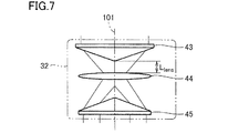
図6は、ワーク上におけるレーザ光の照射領域の大きさを示す図である。図7は、図3中の付加加工用ヘッドにおいて、凸レンズの位置を示す図である。図8は、図3中の付加加工用ヘッドにおいて、レーザ光出射部およびワーク間の位置関係を示す図である。 FIG. 6 is a view showing the size of the irradiation area of the laser beam on the work. FIG. 7 is a view showing the position of the convex lens in the additional processing head in FIG. FIG. 8 is a view showing the positional relationship between the laser beam emitting portion and the work in the additional processing head in FIG.
図6を参照して、ワーク上におけるレーザ光照射領域312の直径(外径)を、「Dring」という(以下、「リングスポット直径Dring」ともいう)。ワーク上におけるレーザ光照射領域312の半径方向における厚みを、「Lring」という(以下、「リング厚みLring」ともいう)。リングスポット直径Dringおよびリング厚みLringが決定されることによって、ワーク上におけるレーザ光照射領域312の大きさが定まる。Referring to FIG. 6, the diameter (outer diameter) of the laser
なお、図6中には、リング形状を有するレーザ光照射領域312が示されているが、ワーク上におけるレーザ光の照射領域は、円形であってもよい。
In addition, although the laser beam irradiation area |
図7を参照して、付加加工用ヘッド21のリング状レーザ光形成部32において、レーザ光の光軸方向におけるアキシコンレンズ43および凸レンズ44間の距離を、「Llens」という(以下、「レンズ間距離Llens」ともいう)。Referring to FIG. 7, the ring-like laser
レンズ間距離Llensの値は、図3中のレンズ移動機構部81による凸レンズ44の移動に伴って変化する。このとき、レーザ光の光軸方向におけるアキシコンレンズ43およびアキシコンレンズ45間の距離は、一定である。The value of the inter-lens distance L lens changes in accordance with the movement of the
図8を参照して、レーザ光出射部34(より具体的には、保護レンズ56)と、レーザ光出射部34から出射されるリング状レーザ光の焦点位置との間の距離を「Lfoc」という(以下、「焦点距離Lfoc」ともいう)。ワーク(より具体的には、付加加工が行なわれるワーク表面)と、レーザ光出射部34から出射されるリング状レーザ光の焦点位置との間の距離を「Llf−wp」という(以下、「焦点ワーク間距離Llf−wp」ともいう)。レーザ光出射部34(より具体的には、保護レンズ56)と、ワーク(より具体的には、付加加工が行なわれるワーク表面)との間の距離を「Lh−wp」という(以下、「ワーク距離Lh−wp」ともいう)。ここで、ワーク距離Lh−wp=焦点距離Lfoc−焦点ワーク間距離Llf−wpの関係が成立する。Referring to FIG. 8, the distance between the laser beam emitting unit 34 (more specifically, the protective lens 56) and the focal position of the ring-shaped laser beam emitted from the laser
材料粉末供給チューブ61の排出口62と、ワーク(より具体的には、付加加工が行なわれるワーク表面)との間の距離を「Lt−wp」という(以下、「チューブワーク間距離Lt−wp」ともいう)。チューブワーク間距離Lt−wpの値は、図3中のチューブ移動機構部86による材料粉末供給チューブ61の移動に伴って変化する。The distance between the
なお、ワーク400に向けて出射されるレーザ光は、その進行方向において、焦点位置に近づくに従って収束する収束区間と、焦点位置から遠ざかるに従って拡散する拡散区間とを有する。図8中に示す例では、ワーク400が、レーザ光の収束区間に位置決めされている。ワーク400がレーザ光の焦点位置付近に位置決めされた場合、ワーク上におけるレーザ光の照射領域が円形となる。
The laser beam emitted toward the
図9は、ワーク上におけるレーザ光の照射領域の大きさを制御するための機構を示すブロック図である。 FIG. 9 is a block diagram showing a mechanism for controlling the size of the irradiation area of laser light on the work.
図3および図6から図9を参照して、加工機械100は、制御装置91を有する。制御装置91は、典型的には、加工機械100に備え付けられる制御盤(コントロールパネル)である。
With reference to FIGS. 3 and 6 to 9, the
制御装置91は、レンズ移動機構部81による凸レンズ44の移動と、工具主軸121による付加加工用ヘッド21の移動と、第1主軸台111によるワークの移動とを制御する。制御装置91は、記憶部92と、制御部93とを有する。
The
記憶部92には、ワーク距離Lh−wpおよびレンズ間距離Llensと、ワーク上に形成されるレーザ光の照射領域の大きさ(リングスポット直径Dring、リング厚みLring)との関係に関するデータが記憶されている。The
制御部93は、ワーク上に形成するレーザ光の照射領域の大きさ(リングスポット直径Dring、リング厚みLring)を特定する。ワーク上に形成するレーザ光の照射領域の大きさの特定は、たとえば、加工機械100の操作パネルを通じてリングスポット直径Dringおよびリング厚みLringが入力されることによって行なわれる。The
制御部93は、特定したレーザ光の照射領域の大きさ(リングスポット直径Dring、リング厚みLring)を、記憶部92に記憶されたデータに照らし合わせることによって、ワーク距離Lh−wpおよびレンズ間距離Llensを決定する。The
制御部93は、決定されたワーク距離Lh−wpが得られるように、工具主軸121および第1主軸台111(第1主軸112)の少なくともいずれか一方の駆動を制御する。制御部93は、決定されたレンズ間距離Llensが得られるように、レンズ移動機構部81の駆動を制御する。The
図10は、ワーク上におけるレーザ光の照射領域の大きさを制御する方法のより具体的な例を示す図である。 FIG. 10 is a diagram showing a more specific example of the method of controlling the size of the irradiation area of the laser beam on the work.
図10を参照して、記憶部92には、リングスポット直径D1ring、D2ringおよびD3ringにおける、レンズ間距離Llensおよびリング厚みLringの関係を示すグラフ98と、リングスポット直径D1ring、D2ringおよびD3ringにおける、レンズ間距離Llensおよび焦点距離Lfocの関係を示すグラフ99とが記憶されている。Referring to FIG. 10, the
まず、制御部93は、ワーク上に形成しようとしているレーザ光の照射領域のリングスポット直径Dring(今回のケースでは、D1ring、D2ringおよびD3ringのいずれか)と、リング厚みLringとを特定する。次に、制御部93は、グラフ98を参照することにより、先のステップで特定したリングスポット直径Dringの曲線において、先のステップで特定したリング厚みLringの値に対応するレンズ間距離Llensの値を求める。First, the
次に、制御部93は、グラフ99を参照することにより、先のステップで特定したリングスポット直径Dringの曲線において、先のステップで得られたレンズ間距離Llensの値に対応する焦点距離Lfocの値を求める。次に、制御部93は、先のステップで得られた焦点距離Lfocの値に基づいて、先のステップで特定したリングスポット直径Dringの値が得られるワーク400の位置を求める。Next, the
以上のステップにより、制御部93は、ワーク上におけるレーザ光の照射領域が特定したリングスポット直径Dringおよびリング厚みLringの大きさとなる、ワーク距離Lh−wp(焦点ワーク間距離Llf−wp)と、レンズ間距離Llensとを決定する。According to the above-described steps, the
リング状レーザ光の大きさは、レーザ光の焦点位置からの距離に応じて、その外径側および内径側の双方において変化するため、単に付加加工用ヘッド21およびワーク間の距離を調整するだけでは、ワーク上におけるレーザ光の照射領域を所望の大きさに設定することができない。本実施の形態では、付加加工用ヘッド21に、凸レンズ44をレーザ光の光軸方向に移動させるレンズ移動機構部81を設けることによって、ワーク上におけるレーザ光の照射領域の大きさを自在に制御することが可能となる。
Since the size of the ring-shaped laser beam changes on both the outer diameter side and the inner diameter side according to the distance from the focal position of the laser beam, it is merely necessary to adjust the distance between the
制御装置91は、図1中のレーザ光発振装置76において発振するレーザ光の出力をさらに制御する。制御部93は、レーザ光の照射領域を変化させた場合に、レーザ光の照射領域の単位面積当たりのエネルギー密度およびメルトプールの温度が一定となるように、レーザ光発振装置76におけるレーザ光の出力を決定してもよい。
The
このような構成によれば、ワークの付加加工中にワーク上におけるレーザ光の照射領域を変化させた場合であっても、ワークに対する材料粉末の積層効率を一定に保つことができる。 According to such a configuration, even when the irradiation area of the laser beam on the work is changed during the additional processing of the work, the lamination efficiency of the material powder on the work can be kept constant.
図10中のレンズ間距離Llensおよびリング厚みLringの関係を示すグラフ98を参照して、リング厚みLringは、レンズ間距離Llensが増大するのに従って、極小値に向けて徐々に減少する第1区間96と、極小値から徐々に増大する第2区間97とを有するように変化する。ここで、第2区間97におけるリング厚みLringの変化の割合は、第1区間96におけるリング厚みLringの変化の割合よりも小さい。言い換えれば、グラフ98において、第2区間97における曲線の傾きは、第1区間96における曲線の傾きよりも緩やかである。Referring to a
このようなグラフ98において、制御部93が、特定したリング厚みLringの値に対応するレンズ間距離Llensの値を求める際に、対応するレンズ間距離Llensの値が、第1区間96および第2区間97のそれぞれに存在する場合がある。この場合に、制御部93は、第2区間97の範囲内において、対応するレンズ間距離Llensの値を決定することが好ましい。In such a
このような構成によれば、リング状レーザ光の厚み(リング厚みLring)をより高精度に制御することができる。According to such a configuration, it is possible to control the thickness (ring thickness L ring ) of the ring-shaped laser beam with higher accuracy.
なお、本発明は、制御部93が、第1区間96の範囲内において、対応するレンズ間距離Llensの値を決定することを排除していない。The present invention does not exclude that the
記憶部92には、ワーク上のスポットにおけるレーザ光の強度分布(図4中の2峰性の正規(ガウス)分布で示される曲線410)と、ワーク上に形成されるレーザ光の照射領域の大きさ(リングスポット直径Dring、リング厚みLring)との関係に関するデータが記憶されてもよい。In the
この場合に、制御部93は、ワーク上に形成するレーザ光の照射領域の大きさ(リングスポット直径Dring、リング厚みLring)を特定するに際して、ワーク上のスポットにおけるレーザ光の強度分布を考慮してもよい。制御部93は、入力されたリングスポット直径Dringに対してリング厚みLringを変化させることによって、または、入力されたリング厚みLringに対してリングスポット直径Dringを変化させることによって、ワーク上のスポットにおけるレーザ光の強度分布を制御する。In this case, when specifying the size (ring spot diameter D ring , ring thickness L ring ) of the irradiation area of the laser beam formed on the workpiece, the
図3、図8および図9を参照して、制御装置91は、チューブ移動機構部86による材料粉末供給チューブ61の移動を制御する。
Referring to FIGS. 3, 8 and 9,
チューブ移動機構部86による材料粉末供給チューブ61の移動に伴い、チューブワーク間距離Lt−wpの値が変化すると、ワーク上における材料粉末の拡散範囲が変化する。制御部93は、ワーク上におけるレーザ光の照射領域に合わせて材料粉末の拡散領域が最適化されるように、チューブ移動機構部86の駆動を制御する。このような構成によれば、ワークの付加加工をより効率的に行なうことができる。When the value of the inter-workpiece distance Lt-wp changes with the movement of the material
図11は、レーザ光の焦点距離Lfocと、チューブワーク間距離Lt−wpとの関係を示す図である。図11(A)中には、レーザ光の焦点距離Lfocが相対的に短い場合が示され、図11(B)中には、レーザ光の焦点距離Lfocが相対的に長い場合が示されている。FIG. 11 is a diagram showing the relationship between the focal length L foc of laser light and the inter- tubework distance L t-wp . FIG. 11A shows the case where the focal length L foc of the laser light is relatively short, and FIG. 11B shows the case where the focal length L foc of the laser light is relatively long. It is done.
図11を参照して、ワークへの材料粉末の付着量を増やすには、チューブワーク間距離Lt−wpが小さいことが好ましい。その一方で、材料粉末供給チューブ61の排出口62をワーク表面に近づけすぎると、材料粉末供給チューブ61の先端部がレーザ光に干渉するおそれが生じる。また、レーザ光の焦点距離Lfocの値が大きいと、レーザ光の先端角が小さくなり、材料粉末供給チューブ61の先端部がレーザ光に干渉し易くなる。Referring to FIG. 11, in order to increase the adhesion amount of the material powder to the work, it is preferable that the tubework distance Lt-wp be small. On the other hand, if the
そこで、制御部93は、図10中のグラフ99において求められるレーザ光の焦点距離Lfocの値に基づいて、材料粉末供給チューブ61とレーザ光との干渉を避けつつ、ワークへの材料粉末の付着量が最大となるように、チューブワーク間距離Lt−wpを決定してもよい。Therefore, based on the value of the focal length L foc of the laser beam determined in the
図12は、図4中の付加加工時のワーク表面の変形例を示す断面図である。図13は、図12中のワーク表面を示す平面図である。 FIG. 12 is a cross-sectional view showing a modification of the workpiece surface at the time of additional processing in FIG. FIG. 13 is a plan view showing the work surface in FIG.
図12および図13を参照して、本変形例では、ワーク400をリング状のレーザ光311の焦点位置付近に位置決めすることによって、ワーク表面に円形のレーザ光照射領域312を形成する。
Referring to FIGS. 12 and 13, in the present modification, by positioning
この際、制御部93は、ワーク表面においてトップハット形のレーザ光の強度分布(図12中の曲線420)が得られるように、レンズ移動機構部81の駆動を制御する。具体的には、ワーク400に向けて照射されるリング状のレーザ光311のリング厚みを増大させることによって、トップハット形のレーザ光の強度分布を得る。
At this time, the
上部が平坦なプロファイルのトップハット形は、上部が尖ったプロファイルのガウシアン形と比較して、レーザ光照射領域312におけるレーザ強度がより均一であるため、ワークの付加加工をより安定して行なうことができる。
The top hat shape of the flat top profile has more uniform laser intensity in the laser
以上に説明した、この発明の実施の形態における付加加工用ヘッド21および加工機械100の基本的な構造についてまとめると、本実施の形態における付加加工用ヘッド21は、ワークに対して材料粉末を供給するとともにレーザ光を照射することにより、付加加工を行なう。付加加工用ヘッド21は、レーザ光の光軸方向において対向して配置される第1アキシコンレンズとしてのアキシコンレンズ43および第2アキシコンレンズとしてのアキシコンレンズ45と、アキシコンレンズ43およびアキシコンレンズ45の間に配置される凸レンズ44とを有し、アキシコンレンズ43に入射されたレーザ光をリング状にしてアキシコンレンズ45より出射するリング状レーザ光形成部32と、凸レンズ44をレーザ光の光軸方向に移動させる第1移動機構部としてのレンズ移動機構部81と、リング状レーザ光をワークに向けて出射するレーザ光出射部34と、レーザ光出射部34から出射されるリング状レーザ光の内側に配置され、材料粉末を排出する排出口62を有し、排出口62からワークに向けて材料粉末を供給する材料供給部としての材料粉末供給チューブ61とを備える。
Summarizing the basic structure of the
また、本実施の形態における加工機械100は、ワークの付加加工が可能な加工機械である。加工機械100は、付加加工用ヘッド21と、付加加工用ヘッド21およびワークを移動させる第3移動機構部としての工具主軸121および第1主軸台111と、レンズ移動機構部81による凸レンズ44の移動、ならびに、工具主軸121および第1主軸台111による付加加工用ヘッド21およびワークの移動を制御する制御装置91とを備える。制御装置91は、ワークおよびレーザ光出射部34間の距離、ならびに、レーザ光の光軸方向におけるアキシコンレンズ43および凸レンズ44間の距離と、ワーク上に形成されるレーザ光の照射領域の大きさとの関係に関するデータを記憶する記憶部92と、ワーク上に形成するレーザ光の照射領域の大きさを特定し、特定したレーザ光の照射領域を記憶部92に記憶されたデータに照らし合わせることにより、ワークおよびレーザ光出射部34間の距離、ならびに、レーザ光の光軸方向におけるアキシコンレンズ43および凸レンズ44間の距離を決定する制御部93とを含む。
In addition, the
このように構成された、この発明の実施の形態における付加加工用ヘッド21および加工機械100によれば、ワーク上におけるレーザ光の照射領域の大きさを自在に制御することができる。
According to the
なお、本実施の形態では、付加加工および除去加工が可能な加工機械100について説明したが、本発明は、付加加工のみ可能な加工機械に適用することも可能である。
Although the
今回開示された実施の形態はすべての点で例示であって制限的なものではないと考えられるべきである。本発明の範囲は上記した説明ではなくて請求の範囲によって示され、請求の範囲と均等の意味および範囲内でのすべての変更が含まれることが意図される。 It should be understood that the embodiments disclosed herein are illustrative and non-restrictive in every respect. The scope of the present invention is shown not by the above description but by the scope of claims, and is intended to include all modifications within the scope and meaning equivalent to the scope of claims.
この発明は、主に、指向性エネルギー堆積法による付加加工に適用される。 The present invention is mainly applied to additive processing by a directed energy deposition method.
21 付加加工用ヘッド、24 ケーブル、26 カバー体、27 開口部、31 レーザ光コリメート部、32 リング状レーザ光形成部、33 レーザ光案内部、34 レーザ光出射部、41 光ファイバー、42 コリメーションレンズ、43,45 アキシコンレンズ、43m,45m 一方面、43n,45n 他方面、44 凸レンズ、46,47 ガイドミラー、48,52,55,57 貫通孔、51,54 集光レンズ、56 保護レンズ、61 材料粉末供給チューブ、62 排出口、70 パウダーフィーダ、71 混合部、72 パウダーホッパー、76 レーザ光発振装置、81 レンズ移動機構部、86 チューブ移動機構部、91 制御装置、92 記憶部、93 制御部、96 第1区間、97 第2区間、98,99 グラフ、100 加工機械、101,102,201,202,203,204,206 中心軸、111 第1主軸台、112 第1主軸、116 第2主軸台、117 第2主軸、121 工具主軸、131 刃物台、132 旋回部、136 ベッド、200 加工エリア、210 スプラッシュガード、311 レーザ光、312 レーザ光照射領域、312p 外周縁、400 ワーク、410 曲線。 21 additional processing head, 24 cable, 26 cover body, 27 opening portion, 31 laser beam collimating portion, 32 ring laser beam forming portion, 33 laser beam guiding portion, 34 laser beam emitting portion, 41 optical fiber, 42 collimation lens, 43, 45 axicon lens, 43 m, 45 m one surface, 43 n, 45 n other surface, 44 convex lens, 46, 47 guide mirror, 48, 52, 55, 55 through hole, 51, 54 condensing lens, 56 protective lens, 61 Material powder supply tube, 62 discharge port, 70 powder feeder, 71 mixing unit, 72 powder hopper, 76 laser light oscillation device, 81 lens moving mechanism unit, 86 tube moving mechanism unit, 91 control device, 92 storage unit, 93 control unit , 96 1st section, 97 2nd section, 98, 99 graph, 100 processing machine, 101, 102, 201, 202, 203, 204, 206 central axis, 111 first spindle head, 112 first spindle, 116 second spindle head, 117 second spindle, 121 tool spindle, 131 tool spindle, 132 turning part, 136 bed, 200 processing area, 210 splash guard, 311 laser light, 312 laser light irradiation area, 312p outer periphery, 400 work, 410 curve.
Claims (5)
レーザ光の光軸方向において対向して配置される第1アキシコンレンズおよび第2アキシコンレンズと、前記第1アキシコンレンズおよび前記第2アキシコンレンズの間に配置される凸レンズとを有し、前記第1アキシコンレンズに入射されたレーザ光をリング状にして前記第2アキシコンレンズより出射するリング状レーザ光形成部と、
前記凸レンズをレーザ光の光軸方向に移動させる第1移動機構部と、
リング状レーザ光をワークに向けて出射するレーザ光出射部と、
前記レーザ光出射部から出射されるリング状レーザ光の内側に配置され、材料粉末を排出する排出口を有し、前記排出口からワークに向けて材料粉末を供給する材料供給部とを備える、付加加工用ヘッド。An additional processing head that performs additional processing by supplying material powder to a workpiece and irradiating it with laser light,
It has a first axicon lens and a second axicon lens disposed opposite to each other in the optical axis direction of laser light, and a convex lens disposed between the first axicon lens and the second axicon lens. A ring-shaped laser beam forming portion configured to ring-form laser light incident on the first axicon lens and to emit the light from the second axicon lens;
A first moving mechanism that moves the convex lens in the optical axis direction of the laser beam;
A laser beam emitting unit for emitting a ring-shaped laser beam toward a work;
And a material supply unit disposed inside the ring-shaped laser light emitted from the laser light emission unit, having a discharge port for discharging the material powder, and supplying the material powder toward the work from the discharge port. Additional processing head.
請求項1または2に記載の付加加工用ヘッドと、
前記付加加工用ヘッドおよびワークの少なくともいずれか一方を移動させる第3移動機構部と、
前記第1移動機構部による前記凸レンズの移動、ならびに、前記第3移動機構部による前記付加加工用ヘッドおよびワークの少なくともいずれか一方の移動を制御する制御装置とを備え、
前記制御装置は、
ワークおよび前記レーザ光出射部間の距離、ならびに、レーザ光の光軸方向における前記第1アキシコンレンズおよび前記凸レンズ間の距離と、ワーク上に形成されるレーザ光の照射領域の大きさとの関係に関するデータを記憶する記憶部と、
ワーク上に形成するレーザ光の照射領域の大きさを特定し、特定したレーザ光の照射領域を前記記憶部に記憶されたデータに照らし合わせることにより、ワークおよび前記レーザ光出射部間の距離、ならびに、レーザ光の光軸方向における前記第1アキシコンレンズおよび前記凸レンズ間の距離を決定する制御部とを含む、加工機械。A processing machine that can perform additional processing of workpieces,
An additional processing head according to claim 1 or 2;
A third moving mechanism that moves at least one of the additional processing head and the work;
The control device controls movement of the convex lens by the first movement mechanism and movement of at least one of the additional processing head and the work by the third movement mechanism.
The controller is
The relationship between the distance between the work and the laser light emitting portion, the distance between the first axicon lens and the convex lens in the optical axis direction of the laser light, and the size of the irradiation area of the laser light formed on the work A storage unit that stores data related to
Identifying the size of the irradiation area of the laser light formed on the work, and comparing the irradiation area of the specified laser light with the data stored in the storage unit, the distance between the work and the laser light emission unit, And a control unit configured to determine a distance between the first axicon lens and the convex lens in a direction of an optical axis of laser light.
前記制御装置は、前記レーザ光発振装置において発振するレーザ光の出力をさらに制御し、
前記制御部は、レーザ光の照射領域を変化させた場合に、レーザ光の照射領域の単位面積当たりのエネルギー密度およびメルトプールの温度が一定となるように、レーザ光の出力を決定する、請求項3に記載の加工機械。The laser light oscillator further includes a laser light oscillation device that oscillates a laser light traveling toward the ring-shaped laser light formation unit,
The control device further controls the output of the laser beam oscillated in the laser beam oscillation device;
The control unit determines the output of the laser light so that the energy density per unit area of the laser light irradiation area and the temperature of the melt pool become constant when the irradiation area of the laser light is changed. A processing machine according to item 3.
前記第2区間におけるリング状レーザ光の厚みの変化の割合は、前記第1区間におけるリング状レーザ光の厚みの変化の割合よりも小さく、
前記制御部は、前記記憶部に記憶されたデータに基づき、前記第2区間の範囲内において、レーザ光の光軸方向における前記第1アキシコンレンズおよび前記凸レンズ間の距離を決定する、請求項3または4に記載の加工機械。The thickness of the ring-shaped laser beam in the radial direction gradually decreases toward the local minimum as the distance between the first axicon lens and the convex lens in the optical axis direction of the laser beam increases; It changes so as to have a second interval that gradually increases from the minimum value,
The rate of change in thickness of the ring-shaped laser beam in the second section is smaller than the rate of change in thickness of the ring-shaped laser beam in the first section,
The control unit determines the distance between the first axicon lens and the convex lens in the optical axis direction of the laser beam within the range of the second section based on the data stored in the storage unit. The processing machine according to 3 or 4.
Applications Claiming Priority (1)
| Application Number | Priority Date | Filing Date | Title |
|---|---|---|---|
| PCT/JP2017/018386 WO2018211594A1 (en) | 2017-05-16 | 2017-05-16 | Additional-processing head and processing machinery |
Publications (2)
| Publication Number | Publication Date |
|---|---|
| JP6535821B2 true JP6535821B2 (en) | 2019-06-26 |
| JPWO2018211594A1 JPWO2018211594A1 (en) | 2019-06-27 |
Family
ID=64274271
Family Applications (1)
| Application Number | Title | Priority Date | Filing Date |
|---|---|---|---|
| JP2018538808A Active JP6535821B2 (en) | 2017-05-16 | 2017-05-16 | Additional processing head and processing machine |
Country Status (4)
| Country | Link |
|---|---|
| US (1) | US11135772B2 (en) |
| EP (1) | EP3626383B1 (en) |
| JP (1) | JP6535821B2 (en) |
| WO (1) | WO2018211594A1 (en) |
Cited By (1)
| Publication number | Priority date | Publication date | Assignee | Title |
|---|---|---|---|---|
| WO2021214899A1 (en) * | 2020-04-22 | 2021-10-28 | 株式会社ニコン | Processing system |
Families Citing this family (12)
| Publication number | Priority date | Publication date | Assignee | Title |
|---|---|---|---|---|
| EP3612337B1 (en) * | 2017-04-19 | 2021-03-17 | Volvo Truck Corporation | A laser brazing system with a jig for contacting the brazing wire and for blocking a first part of a laser beam in association with a detector ;method of monitoring a laser brazing system |
| DE102017219982A1 (en) * | 2017-11-09 | 2019-05-09 | Trumpf Laser- Und Systemtechnik Gmbh | Processing machine for the layer-wise production of three-dimensional components and method for heating a powder |
| US20210170688A1 (en) * | 2018-08-27 | 2021-06-10 | Hewlett-Packard Development Company, L.P. | Modules of three-dimensional (3d) printers |
| KR102188554B1 (en) * | 2019-01-22 | 2020-12-09 | 주식회사 디이엔티 | Laser head optical axis distance adjustment device of metal 3D printer |
| US11686889B2 (en) * | 2019-02-28 | 2023-06-27 | General Electric Company | Systems and methods for direct laser melting of metals using non-diffracting laser beams |
| AT523200B1 (en) * | 2019-11-20 | 2021-10-15 | Univ Graz Tech | DEVICE FOR ADDITIVE MANUFACTURING |
| IT201900023991A1 (en) | 2019-12-13 | 2021-06-13 | Cms Spa | Work center and method for machining pieces |
| US11654512B2 (en) * | 2020-01-10 | 2023-05-23 | John Mehmet Ulgar Dogru | Apparatus and method for 3D laser printing by fusing metal wire material |
| US20230264295A1 (en) * | 2020-06-19 | 2023-08-24 | Dmg Mori Co., Ltd. | Workpiece processing method and processing machine |
| IT202100002981A1 (en) * | 2021-02-10 | 2022-08-10 | Prima Additive S R L | HEAD FOR PROCESSING AN OBJECT USING AN ADDITIVE MANUFACTURING PROCESS OF THE DED TYPE AND RELATED METHOD AND EQUIPMENT |
| CN113953531B (en) * | 2021-10-22 | 2022-07-22 | 西安交通大学 | Method for reducing powder sticking on side surface of laser additive manufacturing part |
| WO2023140326A1 (en) * | 2022-01-20 | 2023-07-27 | 国立研究開発法人物質・材料研究機構 | Method of forming single-crystal or directionally solidified three-dimensional formed objects |
Family Cites Families (18)
| Publication number | Priority date | Publication date | Assignee | Title |
|---|---|---|---|---|
| JPS57102267A (en) | 1980-12-18 | 1982-06-25 | Agency Of Ind Science & Technol | Method and apparatus for melt-spraying by laser |
| JPS62177107A (en) | 1986-01-30 | 1987-08-04 | Agency Of Ind Science & Technol | Apparatus for producing pulverized powder by laser |
| HU900200D0 (en) * | 1989-01-20 | 1990-03-28 | Mezhotras Nt Mikrokhir Glaza | Equipment for surgical treatment of ametropia |
| JPH05208258A (en) * | 1992-01-17 | 1993-08-20 | Nippon Steel Corp | Soldering device |
| FR2823688B1 (en) * | 2001-04-24 | 2003-06-20 | Commissariat Energie Atomique | DEVICE FOR FUSION OF MATERIAL BY LASER BEAM |
| JP2003251480A (en) * | 2002-03-01 | 2003-09-09 | Toyota Motor Corp | Laser cladding device and laser irradiation device |
| DE10240033B4 (en) * | 2002-08-28 | 2005-03-10 | Jenoptik Automatisierungstech | Arrangement for introducing radiant energy into a workpiece made of a weakly absorbing material |
| JP2004322183A (en) | 2003-04-28 | 2004-11-18 | Daido Castings:Kk | Build-up welding apparatus with laser beam |
| JP5184775B2 (en) | 2006-11-28 | 2013-04-17 | リコー光学株式会社 | Optical processing equipment |
| JP5007144B2 (en) | 2007-04-11 | 2012-08-22 | 株式会社ジャパンユニックス | Laser soldering equipment |
| JP4991588B2 (en) | 2008-02-08 | 2012-08-01 | リコー光学株式会社 | Condensing optical system and optical processing apparatus |
| JP2009259860A (en) | 2008-04-11 | 2009-11-05 | Sumitomo Heavy Ind Ltd | Laser processing device, and laser processing method |
| JP5074272B2 (en) * | 2008-04-15 | 2012-11-14 | 株式会社リンクスタージャパン | Processing apparatus and cutting method for brittle material substrate |
| JP5558325B2 (en) | 2010-11-30 | 2014-07-23 | Towa株式会社 | Laser processing equipment |
| GB201316815D0 (en) * | 2013-09-23 | 2013-11-06 | Renishaw Plc | Additive manufacturing apparatus and method |
| JP5805256B1 (en) * | 2014-04-07 | 2015-11-04 | ハイヤグ レーザーテクノロジー ゲーエムベーハーHIGHYAG Lasertechnologie GmbH | Optical devices for beam shaping |
| KR102280355B1 (en) * | 2014-11-14 | 2021-07-21 | 가부시키가이샤 니콘 | Shaping device and shaping method |
| US11173662B2 (en) * | 2015-12-28 | 2021-11-16 | Dmg Mori Co., Ltd. | Additive-manufacturing head, manufacturing machine, and manufacturing method |
-
2017
- 2017-05-16 JP JP2018538808A patent/JP6535821B2/en active Active
- 2017-05-16 EP EP17910234.8A patent/EP3626383B1/en active Active
- 2017-05-16 WO PCT/JP2017/018386 patent/WO2018211594A1/en unknown
- 2017-05-16 US US16/347,025 patent/US11135772B2/en active Active
Cited By (1)
| Publication number | Priority date | Publication date | Assignee | Title |
|---|---|---|---|---|
| WO2021214899A1 (en) * | 2020-04-22 | 2021-10-28 | 株式会社ニコン | Processing system |
Also Published As
| Publication number | Publication date |
|---|---|
| US20190270246A1 (en) | 2019-09-05 |
| EP3626383A1 (en) | 2020-03-25 |
| EP3626383C0 (en) | 2023-09-06 |
| WO2018211594A1 (en) | 2018-11-22 |
| US11135772B2 (en) | 2021-10-05 |
| EP3626383B1 (en) | 2023-09-06 |
| JPWO2018211594A1 (en) | 2019-06-27 |
| EP3626383A4 (en) | 2020-12-16 |
Similar Documents
| Publication | Publication Date | Title |
|---|---|---|
| JP6535821B2 (en) | Additional processing head and processing machine | |
| JP6529610B2 (en) | Additional processing head and processing machine | |
| RU2750313C2 (en) | Method for laser processing of metal material with a high level of dynamic control of the axes of movement of the laser beam along a pre-selected processing path, as well as a machine and a computer program for implementing this method | |
| CN107735209B (en) | Processing machine | |
| US10717156B2 (en) | Additive manufacturing head and manufacturing machine | |
| JP5673813B2 (en) | Laser processing machine | |
| JP2017512896A (en) | Machine tool system and method for additional machining | |
| CN108778610B (en) | Laser processing apparatus and laser processing method | |
| RU2750781C2 (en) | Method for laser processing of a metal material with control of the position of the optical axis of the laser relative to the shielding gas flow, including an installation and computer software for implementing the said method | |
| JP2015178192A (en) | Nozzle, lamination molding device, and production method of lamination molding object | |
| JP6783092B2 (en) | Additional machining heads and machining machines | |
| JP2020533176A (en) | Replaceable optical module for laser machining machines | |
| JP2021115625A (en) | Laminate molding device, laminate molding method and processing path creation method | |
| EP3556509B1 (en) | Combined processing machine with a laser beam splitter | |
| WO2022118492A1 (en) | Processing machine | |
| US20230264295A1 (en) | Workpiece processing method and processing machine | |
| JP7446843B2 (en) | Laser processing equipment, laser processing method, and article manufacturing method |
Legal Events
| Date | Code | Title | Description |
|---|---|---|---|
| A621 | Written request for application examination |
Free format text: JAPANESE INTERMEDIATE CODE: A621 Effective date: 20180724 |
|
| TRDD | Decision of grant or rejection written | ||
| A01 | Written decision to grant a patent or to grant a registration (utility model) |
Free format text: JAPANESE INTERMEDIATE CODE: A01 Effective date: 20190528 |
|
| A61 | First payment of annual fees (during grant procedure) |
Free format text: JAPANESE INTERMEDIATE CODE: A61 Effective date: 20190603 |
|
| R150 | Certificate of patent or registration of utility model |
Ref document number: 6535821 Country of ref document: JP Free format text: JAPANESE INTERMEDIATE CODE: R150 |
|
| R250 | Receipt of annual fees |
Free format text: JAPANESE INTERMEDIATE CODE: R250 |