JP6535239B2 - Toilet bowl cleaning device - Google Patents

Toilet bowl cleaning device Download PDF

Info

Publication number
JP6535239B2
JP6535239B2 JP2015135332A JP2015135332A JP6535239B2 JP 6535239 B2 JP6535239 B2 JP 6535239B2 JP 2015135332 A JP2015135332 A JP 2015135332A JP 2015135332 A JP2015135332 A JP 2015135332A JP 6535239 B2 JP6535239 B2 JP 6535239B2
Authority
JP
Japan
Prior art keywords
rib
opening
hand
washing
toilet bowl
Prior art date
Legal status (The legal status is an assumption and is not a legal conclusion. Google has not performed a legal analysis and makes no representation as to the accuracy of the status listed.)
Expired - Fee Related
Application number
JP2015135332A
Other languages
Japanese (ja)
Other versions
JP2017014862A (en
Inventor
修平 濱田
修平 濱田
雅史 深川
雅史 深川
Current Assignee (The listed assignees may be inaccurate. Google has not performed a legal analysis and makes no representation or warranty as to the accuracy of the list.)
Lixil Corp
Original Assignee
Lixil Corp
Priority date (The priority date is an assumption and is not a legal conclusion. Google has not performed a legal analysis and makes no representation as to the accuracy of the date listed.)
Filing date
Publication date
Application filed by Lixil Corp filed Critical Lixil Corp
Priority to JP2015135332A priority Critical patent/JP6535239B2/en
Publication of JP2017014862A publication Critical patent/JP2017014862A/en
Application granted granted Critical
Publication of JP6535239B2 publication Critical patent/JP6535239B2/en
Expired - Fee Related legal-status Critical Current
Anticipated expiration legal-status Critical

Links

Images

Landscapes

  • Sanitary Device For Flush Toilet (AREA)

Description

本発明は、開口部が設けられた板状部を有するタンクと、開口部を通して配置される導水管と、を備える便器洗浄装置に関する。   The present invention relates to a toilet bowl cleaning apparatus including a tank having a plate-like portion provided with an opening, and a water conduit disposed through the opening.

従来、開口部が設けられた蓋部(板状部)を有する洗浄水タンク(タンク)と、洗浄水タンクの内部に配置される給水部と、洗浄水タンクの上方に配置される手洗部と、蓋部の開口部を通して配置され給水部と手洗部とを接続する導水管と、を備える便器洗浄装置が知られている(例えば、特許文献1及び2参照)。   Conventionally, a washing water tank (tank) having a lid portion (plate-like portion) provided with an opening, a water supply portion disposed inside the washing water tank, and a hand washing portion disposed above the washing water tank There is known a toilet bowl cleaning apparatus including a water conduit disposed through an opening of a lid and connecting a water supply part and a hand washing part (see, for example, Patent Documents 1 and 2).

特開2012−225047号公報JP 2012-225047 A 特開2012−202122号公報JP 2012-202122 A

特許文献1及び2に記載の技術においては、導水管が蓋部の開口部に通して配置されるため、導水管の取り付け作業又は導水管の取り外し作業の際に、導水管が蓋部の開口部の周縁に引っ掛かって、蓋部が外れたり、導水管が擦れて破損してしまう虞がある。特に、導水管が蛇腹状に形成される場合には、導水管は、蓋部の開口部の周縁に引っ掛かりやすい。   In the techniques described in Patent Literatures 1 and 2, since the water conduit is disposed through the opening of the lid, the water conduit is open at the lid during attachment of the water conduit or removal of the water conduit. There is a possibility that the lid may come off or the water conduit may be damaged by being caught by the peripheral edge of the part. In particular, when the water conduit is formed in a bellows shape, the water conduit is likely to be caught around the opening of the lid.

本発明は、導水管が開口部の周縁に引っ掛かることを低減できる便器洗浄装置を提供することを目的とする。   An object of this invention is to provide the toilet bowl washing | cleaning apparatus which can reduce that a water pipe gets caught on the periphery of an opening part.

本発明は、便器本体と、開口部が設けられた板状部を有するタンクと、前記開口部を通して配置され、前記タンクの内部から水を導出し又は前記タンクの内部に水を導入する導水管と、を備え、前記板状部における前記開口部の周縁には、前記板状部における第1面及び/又は前記第1面と反対側の第2面において、前記開口部の貫通方向に延び且つ前記導水管を前記開口部の径方向の内側にガイドするリブ部が形成される便器洗浄装置に関する。   The present invention relates to a tank having a toilet bowl body, a plate-like portion provided with an opening, and a water conduit disposed through the opening to lead out water from the inside of the tank or introduce water into the inside of the tank. And extending in a penetrating direction of the opening on a first surface of the plate and / or a second surface opposite to the first surface on the periphery of the opening on the plate. The present invention also relates to a toilet bowl cleaning apparatus in which a rib for guiding the water conduit to the inside of the opening in the radial direction is formed.

また、前記リブ部は、前記開口部の径方向の内側に凸となる曲線部を有することが好ましい。   Moreover, it is preferable that the said rib part has a curve part which becomes convex inside the radial direction of the said opening part.

また、前記リブ部は、前記開口部の径方向に延びることが好ましい。   Preferably, the rib extends in the radial direction of the opening.

また、前記リブ部は、前記開口部の径方向の内側に延びることが好ましい。   Moreover, it is preferable that the said rib part is extended inside the radial direction of the said opening part.

また、前記リブ部を複数備え、複数の前記リブ部は、前記開口部の周縁に沿って配置され、隣り合う前記リブ部の間隔は、前記導水管の径よりも小さいことが好ましい。   In addition, it is preferable that a plurality of the rib portions be provided, the plurality of the rib portions be disposed along the periphery of the opening, and an interval between the adjacent rib portions be smaller than a diameter of the water conduit.

また、前記導水管は、外面において前記導水管が延びる方向に並んで形成される複数の凸部を有する蛇腹状に形成されることが好ましい。   Further, it is preferable that the water conduit be formed in a bellows shape having a plurality of convex portions formed in the outer surface in a direction in which the water conduit extends.

また、前記リブ部は、前記開口部の径方向の内側に延びており、前記リブ部における前記開口部の貫通方向の長さは、前記導水管における隣り合う前記凸部の間隔よりも長いことが好ましい。   Further, the rib portion extends inward in the radial direction of the opening portion, and a length of the rib portion in the penetration direction of the opening portion is longer than a distance between the adjacent convex portions in the water conduit. Is preferred.

本発明によれば、導水管が開口部の周縁に引っ掛かることを低減できる便器洗浄装置を提供することができる。   ADVANTAGE OF THE INVENTION According to this invention, the toilet bowl washing | cleaning apparatus which can reduce that a water pipe gets caught on the periphery of an opening can be provided.

本発明の一実施形態に係る便器洗浄装置100の側面図である。It is a side view of the toilet bowl cleaning device 100 concerning one embodiment of the present invention. 本発明の一実施形態に係る便器洗浄装置100の正面図である。It is a front view of the toilet bowl cleaning apparatus 100 which concerns on one Embodiment of this invention. 洗浄水タンク20及び手洗い側給水配管33の構成を示す斜視図である。It is a perspective view which shows the structure of the flush water tank 20 and the hand-washing side water supply piping 33. As shown in FIG. 蓋部22に手洗い側給水配管33が通る状態を示す斜視図である。It is a perspective view which shows the state which the hand-washing side water supply piping 33 passes to the cover part 22. FIG. 蓋部22に手洗い側給水配管33が通る状態を示す平面図である。It is a top view which shows the state which the hand-washing side water supply piping 33 passes to the cover part 22. FIG. 図5のA−A線断面図である。It is the sectional view on the AA line of FIG. 図5のB−B線断面図である。It is the BB sectional drawing of FIG.

以下、本発明の便器洗浄装置100の好ましい実施形態について、図面を参照しながら説明する。
まず、本発明の一実施形態に係る便器洗浄装置100の全体構成について、図1〜図3を参照しながら説明する。
Hereinafter, a preferred embodiment of the toilet bowl cleaning device 100 of the present invention will be described with reference to the drawings.
First, the whole structure of the toilet bowl cleaning apparatus 100 which concerns on one Embodiment of this invention is demonstrated, referring FIGS. 1-3.

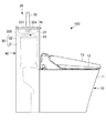
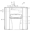
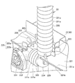
本実施形態の便器洗浄装置100は、図1及び図2に示すように、便器10と、タンクとしての洗浄水タンク20と、手洗い器30と、収納部40と、を備える。
便器10は、便器本体11と、この便器本体11の上部に便器本体11に対して開閉可能に取り付けられる便座12及び便蓋13と、を含んで構成される。
The toilet bowl cleaning device 100 according to the present embodiment, as shown in FIGS. 1 and 2, includes a toilet bowl 10, a flush water tank 20 as a tank, a hand-washer 30, and a storage unit 40.
The toilet bowl 10 includes a toilet body 11, and a toilet seat 12 and a toilet lid 13 which are attached to the upper portion of the toilet body 11 so as to be able to open and close with respect to the toilet body 11.

収納部40は、便器10の後方に配置され、後述する洗浄水タンク20及び各種の配管等を収納する。また、この収納部40の上部には手洗い器30が設けられる。収納部40は、例えば、便器洗浄装置100を設置するトイレルームの一の壁面に沿うように配置される。   The storage unit 40 is disposed at the rear of the toilet bowl 10, and stores the flush water tank 20 and various pipes, which will be described later. In addition, a hand-washer 30 is provided at the top of the storage unit 40. The storage unit 40 is disposed, for example, along one wall surface of the toilet room in which the toilet bowl cleaning device 100 is installed.

手洗い器30は、後述する洗浄水タンク20の上方に配置される。この手洗い器30は、手洗い鉢31と、手洗い吐水管32と、を備える。   The handwasher 30 is disposed above the flush water tank 20 described later. The hand-washer 30 includes a hand-washing pot 31 and a hand-washing spout 32.

手洗い鉢31は、手洗い吐水管32から吐出される手洗い水を受ける。この手洗い鉢31の底部には、排水口(図示せず)が形成されている。排水口(図示せず)は、洗浄水タンク20に排水する。   The hand basin 31 receives the hand wash water discharged from the hand wash spout tube 32. A drain (not shown) is formed at the bottom of the hand-washing pot 31. A drain (not shown) drains to the flush water tank 20.

手洗い吐水管32は、手洗い鉢31から起立するように配置される。この手洗い吐水管32の先端部は、下方に開口している。
手洗い吐水管32の基端部32aは、手洗い側給水配管33(導水管)を介して洗浄水タンク20の内部に配置される給水部(図示せず)に接続される。給水部(図示せず)は、外部から供給される水を給水し、洗浄水タンク20の水位に応じて給水を行うボールタップ(図示せず)などを備えている。
The hand wash and discharge pipe 32 is arranged to stand upright from the hand wash pot 31. The tip of the hand wash and discharge pipe 32 opens downward.
The base end 32 a of the hand-washing water discharge pipe 32 is connected to a water supply portion (not shown) disposed inside the flush water tank 20 via the hand-washing side water supply pipe 33 (water guiding pipe). The water supply unit (not shown) is provided with a ball tap (not shown) that supplies water supplied from the outside and supplies water according to the water level of the flush water tank 20.

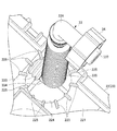
手洗い側給水配管33は、手洗い器30と給水部(図示せず)とを接続し、給水部(図示せず)から供給される水を手洗い器30に導く。手洗い側給水配管33は、図3に示すように、後述する洗浄水タンク20の導出口224を通して配置され、洗浄水タンク20の内部から水を導出する。   The hand-washing side water supply pipe 33 connects the hand-washer 30 and a water supply part (not shown), and guides the water supplied from the water supply part (not shown) to the hand-washer 30. As shown in FIG. 3, the hand-washing side water supply pipe 33 is disposed through an outlet port 224 of the washing water tank 20 described later, and draws water from the inside of the washing water tank 20.

手洗い側給水配管33は、図3〜図6に示すように、洗浄水タンク20の内部に配置された給水部(図示せず)から手洗い器30に向かって順に、図6に示すように、タンク接続部331、第1屈曲部332、第1蛇腹構成部333、第2屈曲部334及び第2蛇腹構成部335の順に連続して接続され、図4及び図5に示すように、第2蛇腹構成部335から、第3屈曲部336及び手洗い器接続部337の順に連続して接続されている。   As shown in FIG. 3 to FIG. 6, the hand-washing side water supply pipe 33 is, as shown in FIG. 6, sequentially from the water supply section (not shown) disposed inside the wash water tank 20 toward the handwasher 30 as shown in FIG. The tank connection portion 331, the first bending portion 332, the first bellows forming portion 333, the second bending portion 334, and the second bellows forming portion 335 are connected in series in this order, as shown in FIGS. The third bending portion 336 and the hand-washer connection portion 337 are connected in series from the bellows configuration portion 335 in this order.

タンク接続部331は、図6に示すように、洗浄水タンク20の内部に配置される。タンク接続部43は、手洗い側給水配管33の上流側の端部を構成し、洗浄水タンク20の内部に配置される給水部(図示せず)に接続される。   The tank connection part 331 is arrange | positioned inside the wash water tank 20, as shown in FIG. The tank connection portion 43 constitutes an end portion on the upstream side of the hand-washing side water supply pipe 33, and is connected to a water supply portion (not shown) disposed inside the flush water tank 20.

第1屈曲部332は、図6に示すように、略L字状に形成され、洗浄水タンク20の内部に配置される。第1屈曲部332は、一端がタンク接続部331に接続され、一端から水平方向に延び所定位置で水平方向の所定方向に屈曲されて他端まで延び、他端が第1蛇腹構成部333の一端に接続される。   As shown in FIG. 6, the first bent portion 332 is formed in a substantially L shape, and is disposed inside the flush water tank 20. The first bending portion 332 has one end connected to the tank connection portion 331, extends horizontally from one end, is bent in a predetermined direction in the horizontal direction at a predetermined position, and extends to the other end, and the other end of the first bellows component 333 Connected to one end.

第1蛇腹構成部333は、図6に示すように、洗浄水タンク20の内部に配置され、水平方向に直線状に延びるように形成される。第1蛇腹構成部333は、一端が第1屈曲部332の他端に接続され、他端が第2屈曲部334の一端に接続される。   As shown in FIG. 6, the first bellows component 333 is disposed inside the washing water tank 20 and formed to extend linearly in the horizontal direction. One end of the first bellows component 333 is connected to the other end of the first bending portion 332, and the other end is connected to one end of the second bending portion 334.

第2屈曲部334は、図6に示すように、略L字状に形成され、洗浄水タンク20の内部に配置される。第2屈曲部334は、一端が第1蛇腹構成部333の他端に接続され、一端から水平方向に延び所定位置で垂直方向に屈曲されて他端まで延び、他端が第2蛇腹構成部335の一端に接続される。   As shown in FIG. 6, the second bent portion 334 is formed in a substantially L shape, and is disposed inside the flush water tank 20. The second bending portion 334 has one end connected to the other end of the first bellows forming portion 333 and extends horizontally from one end and bent in a vertical direction at a predetermined position to extend to the other end, and the other end forms the second bellows forming portion It is connected to one end of 335.

第2蛇腹構成部335は、図4に示すように、垂直方向に直線状に延び、蓋部22に形成される導出口224(後述)を通るように配置される。第2蛇腹構成部335は、蓋部22に形成される導出口224を介して、洗浄水タンク20の内部と外部と亘って配置されている。第2蛇腹構成部335は、一端が第2屈曲部334の他端に接続され、他端が第3屈曲部336の一端に接続される。   As shown in FIG. 4, the second bellows component 335 extends linearly in the vertical direction, and is disposed to pass through an outlet 224 (described later) formed in the lid 22. The second bellows forming portion 335 is disposed across the inside and the outside of the flush water tank 20 via the outlet port 224 formed in the lid 22. One end of the second bellows configuration portion 335 is connected to the other end of the second bending portion 334, and the other end is connected to one end of the third bending portion 336.

第3屈曲部336は、図4に示すように、略L字状に形成され、洗浄水タンク20の外部に配置される。第3屈曲部336は、一端が第2蛇腹構成部335の他端に接続され、一端から垂直方向に延び所定位置で水平方向に屈曲されて他端まで延び、他端が手洗い器接続部337を構成する。手洗い器接続部337は、手洗い側給水配管33の下流側の端部を構成し、手洗い吐水管32の基端部に接続される。   As shown in FIG. 4, the third bent portion 336 is formed in a substantially L shape, and is disposed outside the flush water tank 20. The third bending portion 336 has one end connected to the other end of the second bellows configuration portion 335, extends vertically from one end, is horizontally bent at a predetermined position and extends to the other end, and the other end connects the handwasher connection portion 337 Configure The hand-washer connection portion 337 constitutes the downstream end of the hand-washing side water supply pipe 33, and is connected to the proximal end of the hand-washing water discharge pipe 32.

第1蛇腹構成部333及び第2蛇腹構成部335は、柔軟性を有し、山折り部及び谷折り部が繰り返されて形成された蛇腹状に構成される。本実施形態においては、第1蛇腹構成部333及び第2蛇腹構成部335における蛇腹構成部の山折り部を山状凸部(凸部)331aともいう(図6及び図7参照)。複数の山状凸部331aは、第1蛇腹構成部333及び第2蛇腹構成部335の外面において、手洗い側給水配管33が延びる方向に並んで形成される。これにより、第1蛇腹構成部333及び第2蛇腹構成部335は、屈曲及び伸縮自在に構成される。   The first bellows component 333 and the second bellows component 335 have flexibility, and are formed in a bellows shape in which a mountain fold and a valley fold are repeated. In the present embodiment, the mountain-folded portion of the bellows forming portion in the first bellows forming portion 333 and the second bellows forming portion 335 is also referred to as a mountain-like convex portion (convex portion) 331a (see FIGS. 6 and 7). The plurality of mountain-shaped convex portions 331 a are formed in the outer surface of the first bellows forming portion 333 and the second bellows forming portion 335 in a direction in which the hand-washing side water supply pipe 33 extends. Thus, the first bellows component 333 and the second bellows component 335 are configured to be bendable and stretchable.

手洗い側給水配管33を手洗い器30に取り付ける場合には、タンク接続部331(図6参照)を洗浄水タンク20の内部に配置した給水部(図示せず)に接続した図3に示す状態から、手洗い側給水配管33を、第2蛇腹構成部335の所定部分において屈曲させて、図1及び図2に示すように、手洗い側給水配管33の手洗い器接続部337を手洗い吐水管32の基端部32aに取り付ける。その後、ナット部34によりこれらの接続部分を締め付けることで、手洗い側給水配管33と洗浄水タンク20の内部に配置される給水部(図示せず)とが接続される。   When the hand-washing side water supply pipe 33 is attached to the hand-washing machine 30, the state shown in FIG. 3 in which the tank connection portion 331 (see FIG. 6) is connected to the water supply portion (not shown) disposed inside the wash water tank 20 The hand-washing water supply pipe 33 is bent at a predetermined portion of the second bellows-constituting portion 335 so that the hand-washing water connection pipe 337 of the hand-washing water supply pipe 33 can be Attach to end 32a. Thereafter, by tightening these connection portions by the nut portion 34, the hand-washing side water supply pipe 33 and the water supply portion (not shown) disposed inside the flush water tank 20 are connected.

洗浄水タンク20は、図1及び図2に示すように、便器10の後方かつ上方に配置され、便器本体11を洗浄する洗浄水を貯留する。洗浄水タンク20は、手洗い器30の下方に配置される。この洗浄水タンク20は、図3に示すように、上面が開口したタンク本体21と、このタンク本体21の上面に配置され、タンク本体21の上面を覆う蓋部22(板状部)と、を備える。   As shown in FIGS. 1 and 2, the flush water tank 20 is disposed at the rear and upper side of the toilet bowl 10 and stores flush water for flushing the toilet body 11. The flush water tank 20 is disposed below the handwasher 30. As shown in FIG. 3, the flush water tank 20 includes a tank body 21 having an open upper surface, and a cover 22 (plate-like portion) disposed on the upper surface of the tank body 21 and covering the upper surface of the tank body 21. Equipped with

タンク本体21の内部には、給水部(図示せず)が配置される。洗浄水タンク20は、タンク本体21の内部に給水部(図示せず)が設置された後、蓋部22によりタンク本体21の上面が塞がれて、組み立てられる。   A water supply unit (not shown) is disposed inside the tank body 21. After the water supply unit (not shown) is installed inside the tank body 21, the flush water tank 20 is assembled by closing the upper surface of the tank body 21 by the lid 22.

蓋部22は、タンク本体21の上面に配置され、タンク本体21の上面を覆う。この蓋部22は、図3に示すように、蓋本体221と、外側周壁部222と、導入部223と、開口部としての導出口224と、を備える。   The lid 22 is disposed on the upper surface of the tank body 21 and covers the upper surface of the tank body 21. As shown in FIG. 3, the lid portion 22 includes a lid main body 221, an outer peripheral wall portion 222, an introducing portion 223, and an outlet port 224 as an opening.

蓋本体221は、板状に形成され、タンク本体21の上面の開口を覆う。
外側周壁部222は、蓋本体221の周縁の近傍に設けられ、蓋本体221の上面から上方に立ち上がる。外側周壁部222は、蓋本体221の全周に亘って設けられる。
The lid main body 221 is formed in a plate shape, and covers the opening of the upper surface of the tank main body 21.
The outer peripheral wall portion 222 is provided in the vicinity of the peripheral edge of the lid main body 221, and rises upward from the upper surface of the lid main body 221. The outer peripheral wall portion 222 is provided over the entire circumference of the lid main body 221.

導入部223は、手洗い器30からの排水が導入される。導入部223は、図3に示すように、蓋本体221に形成される。導入部223は、導入凹部223aと、立ち上がり周壁部223bと、を有する。導入凹部223aの底部側には、導入口(図示せず)が設けられている。   The drainage from the hand-washing machine 30 is introduced into the introduction part 223. The introduction portion 223 is formed in the lid main body 221 as shown in FIG. The introducing portion 223 has an introducing recess 223a and a rising peripheral wall 223b. An inlet (not shown) is provided on the bottom side of the introduction recess 223a.

立ち上がり周壁部223bは、導入凹部223aの周囲において、蓋本体211の上面から方形筒状に立ち上がって形成される。
導入凹部223aには、手洗い器30からの排水が導入される。
The rising peripheral wall portion 223 b is formed to rise in a rectangular cylindrical shape from the upper surface of the lid main body 211 around the introduction concave portion 223 a.
The drainage from the hand-washing machine 30 is introduced into the introduction recess 223a.

導出口224は、図3に示すように、蓋本体221における導入部223よりも背面側に形成される。この導出口224には、手洗い側給水配管33が挿通される。   As shown in FIG. 3, the outlet port 224 is formed on the back side of the introduction portion 223 of the lid main body 221. The hand-washing side water supply pipe 33 is inserted into the outlet port 224.

導出口224は、略円形形状で、蓋本体221を貫通して形成される。導出口224には、導水管としての手洗い側給水配管33の第2蛇腹構成部335が通される。   The outlet port 224 has a substantially circular shape and is formed penetrating the lid main body 221. The second bellows configuration portion 335 of the hand-washing side water supply pipe 33 as a water conduit is passed through the outlet port 224.

導出口224の径は、手洗い側給水配管33の第2蛇腹構成部335の径よりも僅かに大きく形成される。導出口224に第2蛇腹構成部335が通された場合には、導出口224と第2蛇腹構成部335との間には、隙間が形成される。導出口224と第2蛇腹構成部335との間の隙間からは、蓋部22の上面に溜まった結露水等が、洗浄水タンク20の内部に流入される。   The diameter of the outlet port 224 is formed to be slightly larger than the diameter of the second bellows component 335 of the hand-washing side water supply pipe 33. When the second bellows component 335 is passed through the outlet 224, a gap is formed between the outlet 224 and the second bellows component 335. Condensed water or the like accumulated on the upper surface of the lid 22 flows into the cleaning water tank 20 from the gap between the outlet 224 and the second bellows component 335.

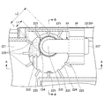
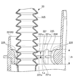
蓋本体221における導出口224の周縁には、図4〜図6に示すように、複数のリブ部225が形成される。複数のリブ部225は、それぞれ、板状に形成される。複数のリブ部225は、それぞれ、蓋本体221の表面(第1面)221a及び裏面(第1面と反対の第2面)221bにおいて、導出口224の貫通方向に延びる。   As shown in FIGS. 4 to 6, a plurality of rib portions 225 are formed on the peripheral edge of the outlet port 224 in the lid main body 221. The plurality of rib portions 225 are each formed in a plate shape. The plurality of rib portions 225 respectively extend in the penetrating direction of the outlet port 224 on the surface (first surface) 221 a and the back surface (second surface opposite to the first surface) 221 b of the lid main body 221.

リブ部225は、導出口224の径方向に延び、かつ、導出口224の径方向の内側に延びる。導出口224の径方向は、導出口224の接線に直交する方向である。本実施形態においては、リブ部225が複数設けられており、複数のリブ部225は、導出口224の周縁において、周方向に並んで、放射状に配置される。   The rib portion 225 extends in the radial direction of the outlet port 224 and extends inward in the radial direction of the outlet port 224. The radial direction of the outlet port 224 is a direction orthogonal to the tangent of the outlet port 224. In the present embodiment, a plurality of rib portions 225 are provided, and the plurality of rib portions 225 are radially arranged side by side in the circumferential direction at the periphery of the outlet port 224.

リブ部225は、それぞれ、導出口224の周方向に視た場合に、図6に示すように、蓋本体221の表面221a及び裏面221bに亘って延びる略半円状に形成される。複数のリブ部225は、図6に示すように、それぞれ、蓋本体221の表面221aから垂直方向の上方側に立ち上がる上方側リブ225a(リブ部)と、蓋本体221の裏面221bから垂直方向の下方側に立ち上がる下方側リブ225b(リブ部)とを有する。上方側リブ225a及び下方側リブ225bは、蓋本体221における導出口224を跨いで連続して形成される。上方側リブ225a及び下方側リブ225bは、手洗い側給水配管33(第2蛇腹構成部335)を導出口224の径方向の内側にガイドする。   When viewed in the circumferential direction of the outlet port 224, each of the rib portions 225 is formed in a substantially semicircular shape extending across the surface 221a and the back surface 221b of the lid main body 221, as shown in FIG. As shown in FIG. 6, the plurality of rib portions 225 are, respectively, an upper side rib 225 a (rib portion) rising upward from the surface 221 a of the lid main body 221 in the vertical direction, and a vertical direction from the back surface 221 b of the lid main body 221. And a lower side rib 225b (rib portion) rising downward. The upper side rib 225a and the lower side rib 225b are continuously formed across the outlet 224 in the lid main body 221. The upper side rib 225 a and the lower side rib 225 b guide the hand-washing side water supply pipe 33 (second bellows component 335) to the inside in the radial direction of the outlet port 224.

複数のリブ部225(上方側リブ225a、下方側リブ225b)は、図6に示すように、それぞれ、導出口224の径方向の内側に凸となる曲線部を有する。具体的には、本実施形態においては、複数のリブ部225は、図6に示すように、それぞれ、導出口224の内側の端部側において、上端部及び下端部の角部が、導出口224の径方向の内側に凸となるように形成された丸みを帯びたアール(R)を有している。なお、リブ部225における角部のアール(R)は、リブ部225の上端部から下端部に連続的に全てアール(R)となっていてもよく、また、上端部及び/又は下端部の部分のみがアール(R)となっていて、その他の部分が直線状になっていてもよい。   Each of the plurality of rib portions 225 (upper side rib 225a and lower side rib 225b) has a curved portion which is convex inward in the radial direction of the outlet port 224, as shown in FIG. Specifically, in the present embodiment, as shown in FIG. 6, at the inner end of the outlet 224, the corners of the upper end and the lower end of the plurality of ribs 225 are the outlet It has a rounded radius (R) formed to be convex inward in the radial direction of 224. In addition, the radius (R) of the corner in the rib portion 225 may be all rounded continuously from the upper end portion to the lower end portion of the rib portion 225, and the upper end portion and / or the lower end portion Only part may be rounded (R) and the other part may be straight.

このようにリブ部225が形成されることで、リブ部225は、蓋本体221の導出口224の周縁のエッジよりも、導出口224の内側に突出して配置される。そのため、手洗い側給水配管33の第2蛇腹構成部335は、第2蛇腹構成部335が移動しても、リブ部225に接触するため、蓋本体221における導出口224の周縁の板状の部分のエッジに接触し難い。   By forming the rib portion 225 in this manner, the rib portion 225 is disposed so as to protrude to the inside of the outlet port 224 more than the edge of the peripheral edge of the outlet port 224 of the lid main body 221. Therefore, the second bellows constituting portion 335 of the hand-washing side water supply pipe 33 contacts the rib portion 225 even if the second bellows constituting portion 335 moves, so the plate-like portion of the periphery of the outlet 224 in the lid main body 221 Hard to touch the edge of

周方向に隣り合うリブ部225の間隔L1は、図5に示すように、手洗い側給水配管33の第2蛇腹構成部335の径L2よりも小さい。具体的には、放射状に配置される複数のリブ部225において、隣り合うリブ部225の間隔は、L1である。手洗い側給水配管33の第2蛇腹構成部335の外形の直径は、L2である。そして、隣り合うリブ部225の間隔L1は、図5に示すように、手洗い側給水配管33の第2蛇腹構成部335の径L2よりも小さく設定されている。
そのため、手洗い側給水配管33が、隣り合うリブ部225に阻まれて、隣り合うリブ部225の間に入り込むことが抑制される。これにより、手洗い側給水配管33は、導出口224の周縁部に引っ掛かり難い。
The distance L1 between the rib portions 225 adjacent in the circumferential direction is smaller than the diameter L2 of the second bellows forming portion 335 of the hand-washing side water supply pipe 33, as shown in FIG. Specifically, in the plurality of rib portions 225 arranged radially, the distance between the adjacent rib portions 225 is L1. The outer diameter of the second bellows component 335 of the hand-washing water supply pipe 33 is L2. And as shown in FIG. 5, the space | interval L1 of the rib part 225 which adjoins is set smaller than the diameter L2 of the 2nd bellows structure part 335 of the hand-washing side water supply piping 33. As shown in FIG.
Therefore, it is suppressed that the hand-washing side water supply piping 33 is obstruct | occluded by the adjacent rib part 225, and entraps between the adjacent rib parts 225. As shown in FIG. Thereby, the hand-washing side water supply piping 33 is hard to be caught by the peripheral part of the outlet 224.

手洗い側給水配管33の第2蛇腹構成部335は、蛇腹状に形成される。手洗い側給水配管33の第2蛇腹構成部335の蛇腹状の部分は、導出口224の周縁部に引っ掛かり難く、蛇腹状の部分が破損し難い。   The 2nd bellows composition part 335 of hand-washing side water supply piping 33 is formed in the shape of a bellows. The bellows-like portion of the second bellows-constituting portion 335 of the hand-washing water supply pipe 33 is less likely to be caught on the peripheral portion of the outlet port 224, and the bellows-like portion is less likely to be damaged.

リブ部225における導出口224の貫通方向の長さLbは、図7に示すように、第2蛇腹構成部335を長さ方向に伸ばした状態において、第2蛇腹構成部335の隣り合う山状凸部331aの間隔Laよりも長い。「第2蛇腹構成部335を長さ方向に伸ばした状態」とは、手洗い側給水配管33の施工時に、第2蛇腹構成部335が引っ張られて長さ方向に伸びる程度の状態である。具体的には、本実施形態においては、手洗い側給水配管33の第2蛇腹構成部335は、山折り及び谷折りが交互に繰り返す蛇腹構造を有している。隣り合う山状凸部331aの間隔とは、山折り部から山折り部までの間の距離である。例えば、図7に示すように、隣り合う山状凸部331aの間隔は、Laである。リブ部225における導出口224の貫通方向の長さは、Lbである。そして、リブ部225における導出口224の貫通方向の長さLbは、図7に示すように、隣り合う山状凸部331aの間隔Laよりも長く設定されている。
そのため、リブ部225は、隣り合う山状凸部331aに阻まれて、手洗い側給水配管33の第2蛇腹構成部335における隣り合う山状凸部331aの間に、入り込むことが抑制される。そのため、手洗い側給水配管33の第2蛇腹構成部335は、導出口224に引っ掛かり難い。
The length Lb of the rib portion 225 in the penetration direction of the outlet port 224 is, as shown in FIG. 7, an adjacent mountain shape of the second bellows component 335 in a state where the second bellows component 335 is elongated in the length direction. It is longer than the interval La of the convex portions 331a. The “state in which the second bellows forming portion 335 is extended in the length direction” is a state in which the second bellows forming portion 335 is pulled to extend in the length direction when the hand-washing water supply pipe 33 is constructed. Specifically, in the present embodiment, the second bellows forming portion 335 of the hand-washing side water supply pipe 33 has a bellows structure in which mountain folding and valley folding are alternately repeated. The distance between the adjacent mountain-shaped convex portions 331 a is the distance between the mountain-folded portion and the mountain-folded portion. For example, as shown in FIG. 7, the distance between adjacent mountain-like convex portions 331 a is La. The length in the penetration direction of the outlet port 224 in the rib portion 225 is Lb. Further, as shown in FIG. 7, the length Lb of the rib portion 225 in the penetration direction of the outlet port 224 is set to be longer than the interval La between the adjacent mountain-like convex portions 331a.
Therefore, the rib portion 225 is inhibited by the adjacent mountain-shaped convex portions 331 a and is prevented from entering between the adjacent mountain-shaped convex portions 331 a in the second bellows-formed portion 335 of the hand-washing water supply pipe 33. Therefore, the second bellows constituting portion 335 of the hand-washing side water supply pipe 33 is not easily caught by the outlet port 224.

以上の洗浄水タンク20には、給水部(図示せず)を介して洗浄水が供給される。
また、タンク本体21の下部には、フロート弁(図示せず)により開閉される排水口が形成されている。そして、フロート弁を引き上げて排水口を開放することにより、タンク本体21の内部に貯留された洗浄水が排水口(図示せず)から流出して便器10に供給され、便器本体11が洗浄される。
Washing water is supplied to the washing water tank 20 described above via a water supply unit (not shown).
Further, a drain port which is opened and closed by a float valve (not shown) is formed in the lower portion of the tank body 21. Then, the float valve is pulled up and the drainage port is opened, so that the flush water stored inside the tank body 21 flows out from the drainage port (not shown) and is supplied to the toilet 10 to wash the toilet body 11. Ru.

以上説明した本実施形態の便器洗浄装置100によれば、以下のような効果を奏する。
本実施形態の便器洗浄装置100は、導出口224が設けられた蓋部22を有する洗浄水タンク20と、導出口224を通して配置され、洗浄水タンク20の内部から水を導出する手洗い側給水配管33と、を備え、蓋本体221における導出口224の周縁には、蓋本体221の表面221a及び裏面221bにおいて、導出口224の貫通方向に延び且つ手洗い側給水配管33(第2蛇腹構成部335)を導出口224の径方向の内側にガイドするリブ部225が形成される。
According to the toilet bowl cleaning device 100 of the present embodiment described above, the following effects can be obtained.
The toilet bowl cleaning apparatus 100 of the present embodiment is disposed through the flush water tank 20 having the lid portion 22 provided with the outlet port 224, and the outlet port 224, and the hand-washing side water supply pipe for extracting water from the inside of the flush water tank 20. 33, and extends in the penetrating direction of the outlet port 224 on the front surface 221a and the back surface 221b of the lid main body 221 at the peripheral edge of the outlet port 224 in the lid main body 221, The rib portion 225 is formed to guide the inside of the outlet port 224 in the radial direction.

そのため、手洗い側給水配管33は、導出口224に通して配置された場合における手洗い側給水配管33の取り付け作業又は外し作業の際に、蓋本体221における導出口224の周縁のエッジに接触よりも、上方側リブ225a又は下方側リブ225bに接触しやすい。これにより、手洗い側給水配管33は、導出口224の径方向の内側にガイドされ、蓋本体221における導出口224の周縁のエッジに接触することが低減され、導出口224の周縁に手洗い側給水配管33が引っ掛かることを低減できる。
また、導出口224の周縁に手洗い側給水配管33が引っ掛かることを低減できるため、手洗い側給水配管33の径に対応させて、導出口224の径を小さくできる。これにより、洗浄水タンク20の内部からの飛沫の飛び出しを低減できると共に、洗浄水タンク20の内部から出される騒音を低減できる。
Therefore, when the hand-washing water supply pipe 33 is disposed through the lead-out port 224, the edge of the peripheral edge of the lead-out port 224 in the lid main body 221 is contacted rather than in contact , The upper side rib 225a or the lower side rib 225b. Thereby, the hand-washing side water supply pipe 33 is guided to the inside in the radial direction of the lead-out port 224, and contact with the edge of the peripheral edge of the lead-out port 224 in the lid main body 221 is reduced. The piping 33 can be reduced.
Further, since the hand-washing side water supply pipe 33 can be prevented from being caught around the periphery of the outlet port 224, the diameter of the outlet port 224 can be made smaller corresponding to the diameter of the hand-washing side water supply pipe 33. As a result, it is possible to reduce the splashing of droplets from the inside of the flush water tank 20 and to reduce the noise emitted from the inside of the flush water tank 20.

リブ部225は、導出口224の径方向の内側に凸となる曲線部を有する。そのため、リブ部225が手洗い側給水配管33に接触しても、手洗い側給水配管33がリブ部225の曲線部に接触するため、手洗い側給水配管33が破損することを低減できる。   The rib portion 225 has a curved portion which is convex inward in the radial direction of the outlet port 224. Therefore, even if the rib portion 225 contacts the hand-washing side water supply pipe 33, the hand-washing side water supply pipe 33 contacts the curved portion of the rib portion 225, so that breakage of the hand-washing side water supply pipe 33 can be reduced.

リブ部225は、導出口224の径方向に延びている。そのため、蓋部22の蓋本体221の上面に溜まった水が、導出口224の径方向に沿って水が導かれるため、水を導出口224に流入させやすい。   The rib portion 225 extends in the radial direction of the outlet port 224. Therefore, the water collected on the upper surface of the lid main body 221 of the lid portion 22 is guided along the radial direction of the outlet port 224, so that the water can easily flow into the outlet port 224.

リブ部225は、導出口224の径方向の内側に延びている。そのため、リブ部225は、蓋部本体の導出口224の周縁の板状のエッジよりも、導出口224の径方向の内側に突出する。これにより、蓋部本体の導出口224の周縁の板状のエッジに接触せずに、リブ部225に接触する。よって、手洗い側給水配管33は、導出口224に引っ掛かり難い。   The rib portion 225 extends radially inward of the outlet port 224. Therefore, the rib portion 225 protrudes inward in the radial direction of the outlet port 224 more than the plate-like edge of the peripheral edge of the outlet port 224 of the lid body. Thereby, the rib 225 is contacted without contacting the plate-like edge of the peripheral edge of the outlet port 224 of the lid body. Therefore, the hand-washing side water supply pipe 33 is hard to be caught by the outlet 224.

隣り合うリブ部225の間隔L1は、手洗い側給水配管33の径L2よりも小さい。そのため、手洗い側給水配管33が、隣り合うリブ部225に阻まれて、隣り合うリブ部225の間に入り込むことが抑制される。これにより、手洗い側給水配管33は、導出口224の周縁部に引っ掛かり難い。   The distance L1 between the adjacent rib portions 225 is smaller than the diameter L2 of the hand-washing water supply pipe 33. Therefore, it is suppressed that the hand-washing side water supply piping 33 is obstruct | occluded by the adjacent rib part 225, and entraps between the adjacent rib parts 225. As shown in FIG. Thereby, the hand-washing side water supply piping 33 is hard to be caught by the peripheral part of the outlet 224.

手洗い側給水配管33の第2蛇腹構成部335は、蛇腹状に形成される。手洗い側給水配管33の第2蛇腹構成部335の蛇腹状の部分は、導出口224の周縁部に引っ掛かり難く、蛇腹状の部分が破損し難い。   The 2nd bellows composition part 335 of hand-washing side water supply piping 33 is formed in the shape of a bellows. The bellows-like portion of the second bellows-constituting portion 335 of the hand-washing water supply pipe 33 is less likely to be caught on the peripheral portion of the outlet port 224, and the bellows-like portion is less likely to be damaged.

リブ部225における導出口224の貫通方向の長さLaは、第2蛇腹構成部335を長さ方向に伸ばした状態において、第2蛇腹構成部335における隣り合う山状凸部331aの間隔Lbよりも長い。そのため、リブ部225は、隣り合う山状凸部331aに阻まれて、手洗い側給水配管33の第2蛇腹構成部335における隣り合う山状凸部331aの間に、入り込むことが抑制される。そのため、手洗い側給水配管33の第2蛇腹構成部335は、導出口224に引っ掛かり難い。   The length La of the lead-out port 224 in the rib portion 225 in the penetration direction is equal to the distance Lb of the adjacent convex convex portions 331 a in the second bellows constituting portion 335 in a state where the second bellows constituting portion 335 is elongated in the length direction. Too long. Therefore, the rib portion 225 is inhibited by the adjacent mountain-shaped convex portions 331 a and is prevented from entering between the adjacent mountain-shaped convex portions 331 a in the second bellows-formed portion 335 of the hand-washing water supply pipe 33. Therefore, the second bellows constituting portion 335 of the hand-washing side water supply pipe 33 is not easily caught by the outlet port 224.

以上、本発明の便器洗浄装置100の好ましい各実施形態について説明したが、本発明は、上述した実施形態に制限されるものではなく、適宜変更が可能である。
例えば、前記実施形態では、導水管を、洗浄水タンク20の内部から手洗い器30に水を導出する手洗い側給水配管33としたが、これに限らない。導水管を、洗浄水タンク20の外部から洗浄水タンク20の内部に水を導入する導水管としてもよい。
As mentioned above, although each preferable embodiment of the toilet bowl cleaning apparatus 100 of this invention was described, this invention is not restrict | limited to embodiment mentioned above, It can change suitably.
For example, in the above embodiment, the water conduit is used as the hand-washing side water supply pipe 33 for leading water from the inside of the washing water tank 20 to the hand-washing device 30, but the invention is not limited thereto. The water conduit may be a water conduit that introduces water from the outside of the flush water tank 20 to the inside of the flush water tank 20.

また、前記実施形態では、導水管を、蛇腹状の第2蛇腹構成部335で構成したが、これに限らない。例えば、導水管を、筒状のゴム管で構成してもよい。   Moreover, in the said embodiment, although the water conduit was comprised by the bellows-like 2nd bellows structure part 335, it does not restrict to this. For example, the water conduit may be constituted by a cylindrical rubber pipe.

また、前記実施形態では、蓋部をタンク本体と別体として、蓋部をタンク本体に対して取り外し可能な構成としたが、これに限らない。洗浄水タンクは一体的に形成されていてもよい。例えば、板状部を、一体的に形成された洗浄水タンクの上壁又は側壁により構成してもよい。   Moreover, in the said embodiment, although the lid part was made into another body from the tank main body and it was set as the structure which can be removed with respect to a tank main body, it does not restrict to this. The flush water tank may be integrally formed. For example, the plate-like portion may be constituted by the upper wall or the side wall of the flush water tank integrally formed.

また、前記実施形態では、上方側リブ225a及び下方側リブ225bを、蓋本体221における導出口224を跨いで連続に形成したが、これに限らない。上方側リブ225a又は下方側リブ225bのうちの一方のみを、蓋本体221の表面221a又は裏面221bに設けるように構成してもよい。   Moreover, in the said embodiment, although the upper side rib 225a and the lower side rib 225b were continuously formed straddling the outlet port 224 in the lid main body 221, it does not restrict to this. Only one of the upper side rib 225a and the lower side rib 225b may be provided on the surface 221a or the back surface 221b of the lid main body 221.

また、前記実施形態では、洗浄水タンク20を覆うカバー部材を、洗浄水タンク20が収納された収納部40と、収納部40の上部に設けられた手洗い器30の手洗い鉢31と、により構成したが、これに限らない。洗浄水タンク20を覆うカバー部材を、例えば、手洗い鉢31で構成される上部カバー部と周方向に囲む側部カバー部とが、樹脂材料により一体的に成型されるタンクカバーで構成してもよい。   Further, in the above embodiment, the cover member for covering the washing water tank 20 is configured by the storage unit 40 in which the washing water tank 20 is stored, and the hand wash bowl 31 of the handwasher 30 provided above the storage unit 40. However, it is not limited to this. Even if the cover member for covering the washing water tank 20 is constituted by, for example, a tank cover integrally molded of a resin material, the upper cover portion constituted by the hand wash pot 31 and the side cover portion surrounding in the circumferential direction Good.

10 便器
20 洗浄水タンク(タンク)
33 手洗い側給水配管(導水管)
100 便器洗浄装置
221 蓋本体(板状部)
221a 表面(第1面)
221b 裏面(第2面)
224 導出口(開口部)
225 リブ部
225a 上方側リブ(リブ部)
225b 下方側リブ(リブ部)
331a 山状凸部(凸部)
10 toilet bowl 20 flush water tank (tank)
33 Hand-washing water supply pipe (conduction pipe)
100 toilet bowl cleaning device 221 lid body (plate-like portion)
221a surface (first surface)
221b back side (second side)
224 outlet (opening)
225 rib 225a upper rib (rib)
225b Lower side rib (rib section)
331a convex (convex)

Claims (6)

便器本体と、
開口部が設けられた板状部を有するタンクと、
前記開口部を通して配置され、前記タンクの内部から水を導出し又は前記タンクの内部に水を導入する導水管と、を備え、
前記板状部における前記開口部の周縁には、前記板状部における第1面及び/又は前記第1面と反対側の第2面において、前記開口部の貫通方向に延び且つ前記導水管を前記開口部の径方向の内側にガイドするリブ部が形成され
前記リブ部は、前記開口部の周方向に厚みを有する板状に形成され、
前記リブ部を複数備え、
複数の前記リブ部は、前記開口部の周縁に沿って配置され、
隣り合う前記リブ部の間隔は、前記導水管の径よりも小さい
便器洗浄装置。
With the toilet bowl body,
A tank having a plate-like portion provided with an opening;
A conduit disposed through the opening for discharging water from the inside of the tank or introducing water into the inside of the tank;
In the periphery of the opening in the plate-like portion, the first surface of the plate-like portion and / or the second surface opposite to the first surface extends in the penetrating direction of the opening and the water conduit A rib is formed to guide radially inward of the opening ,
The rib portion is formed in a plate shape having a thickness in a circumferential direction of the opening portion,
Comprising a plurality of said ribs,
The plurality of rib portions are disposed along the periphery of the opening,
The space between the adjacent rib portions is smaller than the diameter of the water conduit .
前記リブ部は、前記開口部の径方向の内側に凸となる曲線部を有する請求項1に記載の便器洗浄装置。   The toilet bowl cleaning apparatus according to claim 1, wherein the rib portion has a curved portion which is convex inward in the radial direction of the opening. 前記リブ部は、前記開口部の径方向に延びる請求項1又は2に記載の便器洗浄装置。   The toilet bowl cleaning apparatus according to claim 1, wherein the rib extends in the radial direction of the opening. 前記リブ部は、前記開口部の径方向の内側に延びる請求項3に記載の便器洗浄装置。   The toilet bowl cleaning apparatus according to claim 3, wherein the rib extends radially inward of the opening. 前記導水管は、外面において前記導水管が延びる方向に並んで形成される複数の凸部を有する蛇腹状に形成される請求項1からのいずれかに記載の便器洗浄装置。 The toilet bowl cleaning apparatus according to any one of claims 1 to 4 , wherein the water conduit is formed in a bellows shape having a plurality of convex portions formed in a row in a direction in which the water conduit extends in the outer surface. 前記リブ部は、前記開口部の径方向の内側に延びており、
前記リブ部における前記開口部の貫通方向の長さは、前記導水管における隣り合う前記凸部の間隔よりも長い請求項に記載の便器洗浄装置。
The rib extends radially inward of the opening,
The toilet bowl cleaning apparatus according to claim 5 , wherein a length in a penetration direction of the opening in the rib portion is longer than an interval between the adjacent convex portions in the water conduit.
JP2015135332A 2015-07-06 2015-07-06 Toilet bowl cleaning device Expired - Fee Related JP6535239B2 (en)

Priority Applications (1)

Application Number Priority Date Filing Date Title
JP2015135332A JP6535239B2 (en) 2015-07-06 2015-07-06 Toilet bowl cleaning device

Applications Claiming Priority (1)

Application Number Priority Date Filing Date Title
JP2015135332A JP6535239B2 (en) 2015-07-06 2015-07-06 Toilet bowl cleaning device

Publications (2)

Publication Number Publication Date
JP2017014862A JP2017014862A (en) 2017-01-19
JP6535239B2 true JP6535239B2 (en) 2019-06-26

Family

ID=57830167

Family Applications (1)

Application Number Title Priority Date Filing Date
JP2015135332A Expired - Fee Related JP6535239B2 (en) 2015-07-06 2015-07-06 Toilet bowl cleaning device

Country Status (1)

Country Link
JP (1) JP6535239B2 (en)

Family Cites Families (3)

* Cited by examiner, † Cited by third party
Publication number Priority date Publication date Assignee Title
JPH036684Y2 (en) * 1986-02-03 1991-02-20
JPH0625197Y2 (en) * 1988-09-02 1994-07-06 株式会社ケーブイケー Waterproof structure of hose pull-out device
JP3514112B2 (en) * 1998-05-11 2004-03-31 株式会社Inax Connection structure of hand washing spout pipe in washing water tank

Also Published As

Publication number Publication date
JP2017014862A (en) 2017-01-19

Similar Documents

Publication Publication Date Title
WO2017142010A1 (en) Flush toilet
JP2015113633A5 (en)
JP2019052422A (en) Washbowl
JP6535239B2 (en) Toilet bowl cleaning device
JP4709981B2 (en) Drain trap
JP4517868B2 (en) Drain socket
JP5703824B2 (en) Drain trap
JP2011094359A (en) Drain trap
JP2018188857A (en) Drain trap
JP6326578B2 (en) Drainage member
JP2012528269A5 (en)
JP2022097731A (en) Flush toilet bowl
JP6649080B2 (en) Connection structure of hand washing spout pipe
JP6503263B2 (en) Drainage structure of bathroom
KR200479005Y1 (en) For easy cleaning drain trap drain pipe wall
JP6454841B2 (en) Drainage structure with collecting member
JP6370582B2 (en) Connection structure between tank and drain pipe
JP6242650B2 (en) Urinal spreader
JP5674231B2 (en) Flush toilet
JP6808176B2 (en) Flush toilet
JP6796799B2 (en) Flush toilet
JP2008002217A (en) Drain trap
JP6019289B2 (en) Drain trap
JP7180194B2 (en) tank equipment
JP4984324B2 (en) Drain trap

Legal Events

Date Code Title Description
A621 Written request for application examination

Free format text: JAPANESE INTERMEDIATE CODE: A621

Effective date: 20180213

A977 Report on retrieval

Free format text: JAPANESE INTERMEDIATE CODE: A971007

Effective date: 20181218

A131 Notification of reasons for refusal

Free format text: JAPANESE INTERMEDIATE CODE: A131

Effective date: 20190108

A521 Request for written amendment filed

Free format text: JAPANESE INTERMEDIATE CODE: A523

Effective date: 20190227

TRDD Decision of grant or rejection written
A01 Written decision to grant a patent or to grant a registration (utility model)

Free format text: JAPANESE INTERMEDIATE CODE: A01

Effective date: 20190528

A61 First payment of annual fees (during grant procedure)

Free format text: JAPANESE INTERMEDIATE CODE: A61

Effective date: 20190531

R150 Certificate of patent or registration of utility model

Ref document number: 6535239

Country of ref document: JP

Free format text: JAPANESE INTERMEDIATE CODE: R150

S111 Request for change of ownership or part of ownership

Free format text: JAPANESE INTERMEDIATE CODE: R313111

R350 Written notification of registration of transfer

Free format text: JAPANESE INTERMEDIATE CODE: R350

LAPS Cancellation because of no payment of annual fees