JP6019289B2 - Drain trap - Google Patents

Drain trap Download PDF

Info

Publication number
JP6019289B2
JP6019289B2 JP2012252775A JP2012252775A JP6019289B2 JP 6019289 B2 JP6019289 B2 JP 6019289B2 JP 2012252775 A JP2012252775 A JP 2012252775A JP 2012252775 A JP2012252775 A JP 2012252775A JP 6019289 B2 JP6019289 B2 JP 6019289B2
Authority
JP
Japan
Prior art keywords
cylinder member
drain
deodorizing cylinder
trap
shape
Prior art date
Legal status (The legal status is an assumption and is not a legal conclusion. Google has not performed a legal analysis and makes no representation as to the accuracy of the status listed.)
Active
Application number
JP2012252775A
Other languages
Japanese (ja)
Other versions
JP2014101644A (en
Inventor
堀江 進
進 堀江
知久 笹川
知久 笹川
原 和也
和也 原
Original Assignee
丸一株式会社
Priority date (The priority date is an assumption and is not a legal conclusion. Google has not performed a legal analysis and makes no representation as to the accuracy of the date listed.)
Filing date
Publication date
Application filed by 丸一株式会社 filed Critical 丸一株式会社
Priority to JP2012252775A priority Critical patent/JP6019289B2/en
Publication of JP2014101644A publication Critical patent/JP2014101644A/en
Application granted granted Critical
Publication of JP6019289B2 publication Critical patent/JP6019289B2/en
Active legal-status Critical Current
Anticipated expiration legal-status Critical

Links

Images

Landscapes

  • Sink And Installation For Waste Water (AREA)

Description

本発明は、排水トラップに関し、更に詳しくは、特に浴室の排水配管等において使用される、防臭筒を採用した排水トラップに関するものである。   The present invention relates to a drain trap, and more particularly to a drain trap employing a deodorizing cylinder, which is used particularly in a drain pipe of a bathroom.

従来より、洗面台、流し台、浴槽、及び浴槽など、排水を生じる機器(以下「排水機器」と記載)において、生じた排水を処理するため、機器に備えられた槽体、例えば洗面ボウルやシンク、浴槽、防水パンの底面等に排水口を設け、この排水口から下水側に排水配管を配管して、排水を、排水口から下水側に排出する方法が知られている。このような排水配管においては、下水側から臭気や害虫類が屋内側に逆流することを防止するため、通常、臭気や害虫類の逆流を防止する機能を備えた、排水トラップと呼ばれる部材を排水口等排水配管上に配置している。
一例として、図15に、特許文献1に記載された排水トラップを備えた浴室配管の従来例を示す。
Conventionally, in a device that generates drainage (hereinafter referred to as “drainage device”), such as a wash basin, a sink, a bathtub, and a bathtub, in order to treat the generated drainage, a tank provided in the device, such as a wash bowl or a sink A method is known in which a drain outlet is provided on the bottom surface of a bathtub, a waterproof pan, etc., a drain pipe is provided from the drain outlet to the sewage side, and drainage is discharged from the drain outlet to the sewage side. In such a drainage pipe, in order to prevent odors and pests from flowing backward from the sewage side to the indoor side, a member called a drainage trap having a function of preventing the backflow of odors and pests is usually drained. It is placed on the drainage piping such as the mouth.
As an example, FIG. 15 shows a conventional example of a bathroom pipe provided with a drain trap described in Patent Document 1.

図15に図示した従来例の浴室の排水配管は、以下に記載した洗い場パン、排水トラップ、パイプ管、より構成されてなる。
洗い場パンは、浴室の使用者が身体を洗う等する際に利用する防水パンであって、底面に洗い場パン上に生じた排水を排出する取付口を備えてなる。
排水トラップは、洗い場パンの下方に取り付けられる排水トラップであって、以下に記載される、トラップ本体、防臭筒部材、より構成される。
トラップ本体は、上方に排水口を、側面に排出口を、それぞれ設けたケーシングであり、その内部には、排水口からの排水を溜めるオワン部を備えてなる。
防臭筒部材は、上端は排水口に水密的に接続され、下端部分は上記オワン部内に配置される、内部を排水口からの排水が流入する略筒形状を成す部材である。
パイプ管は、硬質樹脂からなる軸方視円形を成す部材であって、直管や曲がり管等から構成され、トラップ本体の排出口から下水側の配管までを接続する。
尚、この特許文献1に記載の従来例では、排水口の形状を開口面積を確保しつつコンパクトにするため、排水口を平面視長方形形状とし、この排水口の形状に合わせて洗い場パンの取付口や防臭筒部材、またトラップ本体の形状も平面視略長方形形状としている。
The drainage pipe of the bathroom of the conventional example shown in FIG. 15 is constituted by the washing place pan, the drain trap, and the pipe pipe described below.
The washroom pan is a waterproof pan that is used when the user of the bathroom is washing the body, and has a mounting opening for discharging drainage generated on the washroom pan on the bottom surface.
The drain trap is a drain trap attached below the washing pan, and includes a trap body and a deodorizing cylinder member described below.
The trap body is a casing provided with a drain port on the upper side and a discharge port on the side surface. The trap body has an Owan portion for collecting drainage from the drain port.
The deodorizing cylinder member is a member having a substantially cylindrical shape in which the upper end is connected to the drain port in a watertight manner and the lower end portion is disposed in the Owan portion, and the drainage from the drain port flows into the inside.
The pipe pipe is a member made of hard resin and having a circular shape in an axial direction, and is constituted by a straight pipe, a bent pipe, or the like, and connects from the discharge port of the trap body to the sewage side pipe.
In the conventional example described in Patent Document 1, in order to make the shape of the drain port compact while ensuring the opening area, the drain port has a rectangular shape in plan view, and the washing pan is attached in accordance with the shape of the drain port. The shape of the mouth, the deodorizing cylinder member, and the trap body are also substantially rectangular in plan view.

上記のように構成された、特許文献1の従来例に記載された排水トラップは、以下のようにして洗い場パンに施工される。
まず、トラップ本体の排出口を、パイプ管を介して下水側の配管に接続する。この時は自然勾配によって、排出口から床下配管まで排水が流れるような下り勾配を設定する。次に、洗い場パンの取付口に、トラップ本体の排水口を接続固定する。最後に、排水口に防臭筒部材を、防臭筒部材の下端がオワン部内に配置されるように接続して、従来例の排水トラップ配管の接続が完了する。
The drain trap described in the conventional example of Patent Document 1 configured as described above is applied to a washing place pan as follows.
First, the discharge port of the trap body is connected to the sewage side pipe through a pipe pipe. At this time, a descending slope is set so that the drainage flows from the outlet to the underfloor pipe by a natural slope. Next, the drain outlet of the trap body is connected and fixed to the attachment hole of the washing area pan. Finally, the deodorizing cylinder member is connected to the drain outlet so that the lower end of the deodorizing cylinder member is disposed in the Owan portion, and the connection of the drain trap pipe of the conventional example is completed.

上記のように構成された従来の排水トラップにおいて、洗い場パン上に排水が生じると、排水は、排水口から、防臭筒部材内部を通過し、オワン部内に溜まる。更に排水が流れると、オワン部の上縁から溢れ出て、トラップ本体内部を通過し、排出口からパイプ管を介して下水側に排出される。
ここで、下水側から屋内側である排水口に至るまでの流路上に、オワン部内に溜まった排水によって、排水の流路が常に満水状態となる部分が生じる。この満水状態の流路を、下水側の臭気や害虫類は通過できないため、下水側の臭気や害虫類が屋内側に侵入することが防止される。
このように、下水など下流側から、臭気や害虫類が屋内など上流側に逆流することを防ぐ機能を「トラップ機能」と呼ぶ。またオワン部内に溜まった排水を「封水」、配管の排水を溜めてトラップ機能を生じさせる部分を「封水部」と呼ぶ。
In the conventional drain trap configured as described above, when drainage is generated on the washing place pan, the drainage passes through the inside of the deodorizing cylinder member from the drainage port and accumulates in the Owan portion. When the drainage further flows, it overflows from the upper edge of the Owan portion, passes through the inside of the trap body, and is discharged from the discharge port to the sewage side through the pipe pipe.
Here, on the flow path from the sewage side to the drain outlet on the indoor side, there is a portion where the flow path of the drainage is always full due to the drainage accumulated in the Owan part. Since the sewage-side odors and pests cannot pass through this full flow path, the sewage-side odors and pests are prevented from entering the indoor side.
In this way, the function of preventing odors and pests from flowing backward from the downstream side such as sewage to the upstream side such as indoors is called a “trap function”. Also, the drainage accumulated in the Owan part is called “sealing water”, and the part that collects the drainage of the pipe and causes a trap function is called “sealing part”.

特開2012−180653号JP 2012-180653 A

排水トラップの、排水が流入する排水口は、回転ロックによる接続構造の都合などから平面視円形形状を成すものが殆どであったが、開口面積を確保しつつコンパクトにする、また意匠性を高める等の目的から、特許文献1に記載の従来例のように、非円形形状、例えば平面視長方形形状の排水口と、それに合致する防臭筒部材が採用される場合が増加している。
このような、非円形形状を成す排水口と防臭筒部材を水密的に接続する場合、接続の方法は幾つか提案されているが、構造の簡易さ等から、防臭筒部材の側面にパッキングを環状に配置した上で、排水口にパッキングを介して防臭筒部材を嵌合させて水密的に接続する方法が採用される場合が多い。
しかしながら、このような側面方向で水密的な接続を行うような方法では、以下に記載するような問題が生じる場合があった。
通常、トラップ本体や防臭筒部材は、ABSやポリエチレンなど硬質の樹脂にて成型される。このため、強い応力を受けると排水トラップの各部材は弾性変形により撓みを生じる場合がある。
排水トラップの排水口と防臭筒部材の接続のように、水密的な接続を行うため、パッキングやパッキングを挟んで対向する他の部材に強い圧力で当接する必要がある構造では、当接の圧力によって樹脂が弾性変形してしまい、充分な圧力を持って部材とパッキング(又はパッキングを介して部材同士)が当接できなくなる場合があった。
このようにして樹脂部材に弾性変形が生じ、充分な圧力を持って部材とパッキング(又はパッキングを介して部材同士が)が当接できなくなると、不充分な圧力での当接部分に隙間が生じ、この隙間部分から排水や臭気が洩れてしまう、といった問題があった。
本発明は上記問題点に鑑み発明されたものであって、平面視非円形形状を成す排水口と防臭筒部材を採用し、両者が側面部分にて水密的に接続するように構成されている排水トラップにおいて、部材の弾性変形による漏水や臭気の漏れを防止した排水トラップを提供するためのものである。
Most drain outlets of drain traps have a circular shape in plan view due to the connection structure of the rotation lock, etc., but make the opening area compact and enhance the design. For these purposes, as in the conventional example described in Patent Document 1, there is an increasing number of cases where a non-circular drainage outlet having a rectangular shape, for example, a rectangular shape in plan view, and a deodorizing cylinder member that matches the drainage outlet are employed.
When such a non-circular drainage port and a deodorizing cylinder member are connected in a watertight manner, several connection methods have been proposed, but packing is provided on the side surface of the deodorizing cylinder member for simplicity of structure. In many cases, a method is adopted in which a deodorizing cylinder member is fitted into a drain outlet through a packing and connected in a watertight manner after being arranged in an annular shape.
However, in such a method that performs watertight connection in the lateral direction, problems as described below may occur.
Usually, the trap body and the deodorizing cylinder member are molded from a hard resin such as ABS or polyethylene. For this reason, when receiving a strong stress, each member of the drain trap may be bent due to elastic deformation.
In order to make a watertight connection, such as the connection between the drain outlet of the drain trap and the deodorizing cylinder member, in the structure where it is necessary to abut against the packing or other member facing the packing with a strong pressure, the abutting pressure As a result, the resin is elastically deformed, and the member and the packing (or the members through the packing) cannot be brought into contact with each other with sufficient pressure.
In this way, when the resin member is elastically deformed and the member and the packing (or the members through the packing) cannot contact each other with sufficient pressure, there is a gap in the contact portion with insufficient pressure. There was a problem that drainage and odor leaked from this gap.
The present invention has been invented in view of the above-described problems, and employs a drain port and a deodorizing cylinder member having a non-circular shape in plan view, and is configured such that both are connected in a watertight manner at a side surface portion. In the drain trap, the drain trap is provided to prevent leakage of water and odor due to elastic deformation of members.

請求項1に記載の本発明は、上方に流入口2を、側面に排出口3を、それぞれ設けたケーシングであるトラップ本体1と、トラップ本体1内部に備えられた、流入口2からの排水を溜めるオワン部4と、流入口2に対し水密的に接続するように設けられた、排水が流入する排水口5と、略筒形状を成す部材であって、上方は排水口5に水密的に接続され、下端部分は上記オワン部4内に配置される、内部を排水口5からの排水が流入する防臭筒部材6と、から構成される排水トラップにおいて、
上記防臭筒部材6を、筒形状部分の側面において、排水口5と水密的に接続するように構成すると共に、防臭筒部材6の水密に接続する部分において、防臭筒部材6及び排水口5を、防臭筒部材6の軸方向視非円形の略同一形状とし、且つ少なくとも長辺の一つ以上に、防臭筒部材6又は排水口5のいずれか一方より、防臭筒部材6又は排水口5の他方に向かって膨出する膨出形状を設けたことを特徴とする、排水トラップである。
尚、ここで言う「防臭筒部材及び排水口の長辺」という表現は、「防臭筒部材及び排水口を形成する辺のうち、最も短い辺以外の辺」という意味を表す表現である。
The present invention described in claim 1 includes a trap body 1 that is a casing provided with an inlet 2 on the upper side and an outlet 3 on a side surface, and drainage from the inlet 2 provided inside the trap body 1. Is a water-tight connection to the inflow port 2, the drainage port 5 into which the drainage flows, and a substantially cylindrical member, the upper part being watertight to the drainage port 5. In the drain trap comprised of the deodorizing cylinder member 6 into which the drainage from the drainage port 5 flows inside, the lower end portion being disposed in the Owan portion 4,
The deodorizing cylinder member 6 is configured so as to be watertightly connected to the drainage port 5 on the side surface of the cylindrical portion, and the deodorizing cylinder member 6 and the drainage port 5 are connected to the watertight connection of the deodorizing cylinder member 6. The deodorizing cylinder member 6 has substantially the same non-circular shape when viewed in the axial direction, and at least one of the long sides has at least one of the deodorizing cylinder member 6 and the drainage port 5 and the deodorization cylinder member 6 or the drainage port 5. It is a drainage trap provided with the bulging shape which bulges toward the other.
Note that the expression “the long sides of the deodorizing cylinder member and the drain outlet” referred to here is an expression representing the meaning of “sides other than the shortest side among the sides forming the deodorizing cylinder member and the drain outlet”.

請求項2に記載の本発明は、上方に流入口2を、側面に排出口3を、それぞれ設けたケーシングであるトラップ本体1と、トラップ本体1内部に備えられた、流入口2からの排水を溜めるオワン部4と、流入口2に対し水密的に接続するように設けられた、排水が流入する排水口5と、略筒形状を成す部材であって、上方は排水口5に水密的に接続され、下端部分は上記オワン部4内に配置される、内部を排水口5からの排水が流入する防臭筒部材6と、から構成される排水トラップにおいて、
上記防臭筒部材6を、筒形状部分の側面において、排水口5と水密的に接続するように構成すると共に、防臭筒部材6の水密に接続する部分において、防臭筒部材6及び排水口5を、防臭筒部材6の軸方向視複数の頂点を有する非円形の略同一形状とし、且つ少なくとも頂点間の一つ以上の辺に、防臭筒部材6又は排水口5のいずれか一方より、防臭筒部材6又は排水口5の他方に向かって膨出する膨出形状を設けたことを特徴とする、排水トラップである。
The present invention according to claim 2 is a trap body 1 which is a casing provided with an inlet 2 on the upper side and an outlet 3 on a side surface, and drainage from the inlet 2 provided inside the trap body 1. Is a water-tight connection to the inflow port 2, the drainage port 5 into which the drainage flows, and a substantially cylindrical member, the upper part being watertight to the drainage port 5. In the drain trap comprised of the deodorizing cylinder member 6 into which the drainage from the drainage port 5 flows inside, the lower end portion being disposed in the Owan portion 4,
The deodorizing cylinder member 6 is configured so as to be watertightly connected to the drainage port 5 on the side surface of the cylindrical portion, and the deodorizing cylinder member 6 and the drainage port 5 are connected to the watertight connection of the deodorizing cylinder member 6. The deodorizing cylinder member 6 has a substantially non-circular shape having a plurality of vertices as viewed in the axial direction, and at least one or more sides between the vertices from either the deodorizing cylinder member 6 or the drainage port 5. The drain trap is characterized by having a bulging shape that bulges toward the other of the member 6 or the drain port 5.

請求項3に記載の本発明は、上記膨出形状を、辺自体に設けた、膨出形状としての略円弧形状としたことを特徴とする、段落0008又は段落0009に記載の排水トラップである。   The present invention described in claim 3 is the drain trap according to paragraph 0008 or paragraph 0009, wherein the bulging shape is a substantially arc shape as the bulging shape provided on the side itself. .

請求項4に記載の本発明は、上記防臭筒部材6及び排水口5の、両者が水密的に接続する部分の形状を、
防臭筒部材6の筒部分の軸方向視略長方形形状とし、この略長方形形状の長辺部分に膨出形状を設けたことを特徴とする、段落0008乃至段落0010のいずれか一つに記載の排水トラップである。
In the present invention according to claim 4, the shape of the part where both the deodorizing cylinder member 6 and the drain port 5 are connected in a watertight manner,
Paragraph 0008 to Paragraph 0010, characterized in that the cylinder portion of the deodorizing cylinder member 6 has a substantially rectangular shape when viewed in the axial direction, and a bulging shape is provided on the long side portion of the substantially rectangular shape. It is a drain trap.

請求項5に記載の本発明は、上記排水トラップの防臭筒部材6において、防臭筒部材6の変形を防止する形状保持構造を備えたことを特徴とする、段落0008乃至段落0011のいずれか一つに記載の排水トラップである。   According to a fifth aspect of the present invention, in any one of the paragraphs 0008 to 0011, the deodorizing cylinder member 6 of the drain trap is provided with a shape retaining structure that prevents the deformation of the deodorizing cylinder member 6. It is a drainage trap described in one.

請求項6に記載の本発明は、上記排水トラップの防臭筒部材6において、防臭筒部材6の変形を防止する形状保持構造を、防臭筒部材6の筒形状部分の内部を結ぶ支持リブ6bとしたことを特徴とする、段落0012に記載の排水トラップである。   In the deodorizing cylinder member 6 of the drain trap, the present invention described in claim 6 includes a support rib 6b that connects a shape holding structure that prevents the deformation of the deodorizing cylinder member 6 to the inside of the cylindrical portion of the deodorizing cylinder member 6. The drainage trap according to paragraph 0012, wherein

請求項7に記載の本発明は、上記排水トラップの防臭筒部材6において、防臭筒部材6の変形を防止する形状保持構造を、防臭筒部材6の側面に設けた、折れ曲がり部6cとしたことを特徴とする、段落0012に記載の排水トラップである。   In the deodorizing cylinder member 6 of the drain trap, the present invention described in claim 7 is configured such that the shape holding structure for preventing the deformation of the deodorizing cylinder member 6 is a bent portion 6c provided on the side surface of the deodorizing cylinder member 6. The drain trap according to paragraph 0012, characterized in that

請求項8に記載の本発明は、上記排水トラップにおいて、流入口2と排水口5を兼用したことを特徴とする、段落0008乃至段落0014のいずれか一つに記載の排水トラップである。   The present invention according to claim 8 is the drainage trap according to any one of paragraphs 0008 to 0014, wherein the drainage trap is used as both the inflow port 2 and the drainage port 5.

請求項1、請求項2に記載の本発明では、排水口及び防臭筒部材の接続箇所が軸方向視非円形形状の場合に、防臭筒部材又は排水口のいずれか一方より、防臭筒部材又は排水口の他方に向かって膨出する膨出形状を設けたことで、部材の弾性変形を防止し、排水口及び防臭筒部材の水密的な接続を行うことができる。
請求項3に記載の本発明では、膨出形状の具体的形状を明確にすることができる。
請求項4に記載の本発明では、排水口及び防臭筒部材の両者が水密的に接続する部分の具体的形状を明確にすることができる。
請求項5に記載の本発明では、防臭筒部材に形状保持構造を備えたことによって、弾性変形をより確実に防止することができる。
請求項6、請求項7に記載の本発明では、上記形状保持構造の具体的構成を明確にすることができる。
請求項8に記載の本発明では、上記形状保持構造の具体的構成を明確にすることができる。
In this invention of Claim 1, Claim 2, when the connection location of a drain port and a deodorizing cylinder member is non-circular shape seeing in the axial direction, from either one of a deodorizing cylinder member or a drain port, a deodorizing cylinder member or By providing a bulging shape that bulges toward the other side of the drain port, elastic deformation of the member can be prevented, and the drain port and the deodorizing cylinder member can be connected in a watertight manner.
In this invention of Claim 3, the specific shape of a bulging shape can be clarified.
In this invention of Claim 4, the specific shape of the part which both a drain outlet and a deodorizing cylinder member connect watertightly can be clarified.
In this invention of Claim 5, an elastic deformation can be prevented more reliably by providing the shape retention structure in the deodorizing cylinder member.
In the present invention described in claims 6 and 7, the specific configuration of the shape retaining structure can be clarified.
In this invention of Claim 8, the specific structure of the said shape maintenance structure can be clarified.

第一実施例の排水配管の断面図である。It is sectional drawing of the drain piping of a 1st Example. 図1の排水トラップの一部を切り欠きした斜視図である。It is the perspective view which notched a part of drain trap of FIG. 第一実施例の排水トラップの部材構成を示す断面図である。It is sectional drawing which shows the member structure of the drain trap of 1st Example. 図3の排水トラップの部材構成を示す一部を切り欠きした斜視図である。It is the perspective view which notched a part which shows the member structure of the drain trap of FIG. 第一実施例の防臭筒部材を示す断面図である。It is sectional drawing which shows the deodorizing cylinder member of a 1st Example. 第二実施例の排水配管の断面図である。It is sectional drawing of the drain piping of a 2nd Example. 図6の排水トラップの一部を切り欠きした斜視図である。It is the perspective view which notched some drain traps of FIG. 第二実施例の排水トラップの部材構成を示す断面図である。It is sectional drawing which shows the member structure of the drain trap of 2nd Example. 図8の排水トラップの部材構成を示す一部を切り欠きした斜視図である。It is the perspective view which notched a part which shows the member structure of the drain trap of FIG. 第二実施例の防臭筒部材を示す断面図である。It is sectional drawing which shows the deodorizing cylinder member of a 2nd Example. 他の実施例の防臭筒部材を示す斜視図である。It is a perspective view which shows the deodorizing cylinder member of another Example. 図11実施例の防臭筒部材の平面図である。It is a top view of the deodorizing cylinder member of FIG. 11 Example. 他の実施例の防臭筒部材を示す斜視図である。It is a perspective view which shows the deodorizing cylinder member of another Example. 図13の実施例の防臭筒部材の平面図である。It is a top view of the deodorizing cylinder member of the Example of FIG. 従来の排水トラップを示す斜視図である。It is a perspective view which shows the conventional drain trap.

以下に、本発明の第一実施例について、図面を参照しつつ説明する。
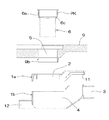
図1乃至図5に図示した第一実施例の排水トラップは、浴室の排水配管に採用される排水トラップに関するものであって、以下に記載した浴槽7、浴槽パン8、洗い場パン9、排水トラップ、エルボ部材10、パイプ管P、等より構成されてなる。
浴槽7は、上方に開口した直方体形状の槽体であって、底面に浴槽7内部に生じた排水を排出する浴槽排水口7aと、この浴槽排水口7aからの排水をエルボ部材10に接続する排水栓部材7bを備えてなる。
浴槽パン8は、上記浴槽7を載置する防水パンであって、底面に浴槽パン8上に生じた排水を排出する浴槽パン排水口8aを備えてなる。
洗い場パン9は、浴室の使用者が身体を洗う等する際に利用する防水パンであって、底面に洗い場パン9上に生じた排水を排出する取付口9aを備えてなる。
排水トラップは、洗い場パン9の下方に取り付けられる排水装置であって、以下に記載される、トラップ本体1、防臭筒部材6、より構成される。
トラップ本体1は、以下に記載する、本体上部1a、本体下部1bの2つの部材の組み合わせによって構成される部材である。本体上部1a、本体下部1bを組み合わせたトラップ本体1の状態では、上方に流入口2と兼用した排水口5を、側面に排出口3を、それぞれ設けたケーシングであり、その内部には、排水口5からの排水を溜めるオワン部4を備えてなる。また、側面のオワン部4に連通する位置に、エルボ部材10を接続する枝管部12を備えてなる。
更にトラップ本体1を構成する本体上部1a、本体下部1bの各部材について以下に詳述する。
本体上部1aは、平面視略長方形形状を成す板状の部材で、周縁には、図3に示したように本体下部1b上縁の外側面部分を覆う受け部11を設けてなる。また、上面には排水口5を備えてなる。
排水口5は平面視略長方形形状を成す部材であって、長方形形状の長辺に当たる2つの辺は排水口5の中心から外方向、即ち排水口5の周縁方向に向かって略円弧状に膨出する膨出形状を設けてなる。
略長方形形状の短辺に当たる辺は直線形状を備えてなる。
また、短辺と円弧形状を備えた長辺との交差部分は小径の円弧形状、いわゆるR形状を形成してなる。
略長方形形状を成す排水口5の、円弧形状を備えた長辺と、直線形状を成す短辺について、直線形状を成す短辺に対し、長辺に備えられた円弧形状(またはその円弧形状の延長線)は正接しておらず、両者の交差部分には頂点が形成されている。即ち、長辺部分は、排水口5の中心から排水口5の内周面に向かって、隣接する辺に正接しない、膨出形状としての円弧形状を備えてなる。
尚、排水口5の、円弧形状を備えた長辺と、直線形状を成す短辺とが交差する頂点部分には、小径の円弧、いわゆるR形状を構成してなる。
本体下部1bは、平面視略長方形形状を成す上方に開口した箱状の部材で、開口の周縁は本体上部1aの受け部11に嵌め込まれるように構成されてなる。また側面に、下水側への配管接続を行うパイプ管Pが接続される排出口3が設けられてなる。また、本体下部1bを成す箱体は、底面が排出口3に向かって昇り勾配となる傾斜面を設けてなり、本体下部1bの側面及び底面と傾斜面によって、使用時にトラップ本体1の排水溜まり部分となるオワン部4を形成する。また、側面のオワン部4に連通する位置に、エルボ部材10を接続する枝管部12を備えてなる。
本体上部1aと下部は、本体上部1aの受け部11、または本体下部1bの周縁に接着剤を用い、本体上部1aと本体下部1bを貼り合わせることでトラップ本体1として完成する。トラップ本体1は、通常の使用においては、本実施例を含め、本体上部1aと本体下部1bとを接着し、トラップ本体1として完成させた状態で、施工現場などに納入される。
防臭筒部材6は、上端は排水口5に水密的に接続され、下端部分はオワン部4内に配置される、内部を排水口5からの排水が流入する軸方向視略長方形の筒形状を成す部材である。
更に詳述すると、防臭筒部材6は、図5に示したように、上方の外側面に、排水口5の内側面と全周に渡って水密的に接続する接続部6aを備えてなる。該接続部6aは、ゴムなどの弾性素材からなるシール部材である環状パッキングPKを備え、防臭筒部材6の軸方向視(即ち平面視)、環状パッキングPKを介して排水口5に略同一形状となる略長方形形状、即ち排水口5の中心から排水口5の内周面に向かって、隣接する辺に正接しない、円弧形状を成す膨出形状を備えた長辺と、この円弧形状に正接しない直線形状を成す短辺を備えてなる。
尚、防臭筒部材6及び排水口5の、円弧形状を備えた長辺と、直線形状を成す短辺とが交差する頂点部分には、小径の円弧、いわゆるR形状を構成してなる。
また、防臭筒部材6は、防臭筒部材6の変形を防止する形状保持構造として、以下に詳述する支持リブ6b及び折れ曲がり部6cを備えてなる。
支持リブ6bは、防臭筒部材6の筒形状部分の内部、詳しくは長辺の円弧部分の中央部分同士を結ぶように設けられたリブ片である。
折れ曲がり部6cは、図3、図4に示したように、防臭筒部材6の円弧形状を成す側面であって、接続部6aよりも下方に設けた、断面視内側に向けて2度屈曲する曲がり部分である。この折れ曲がり部6cよりも下方では、防臭筒部材6は、軸方向視直線形状の辺に囲まれた、ほぼ正確な長方形形状を成し、円弧形状を成す膨出形状を備えない。
防臭筒部材6の接続部6aの外側面と、排水口5に設けられた円弧形状を成す膨出部分において、膨出の程度については特に限定する物ではないが、弾性変形を防止する機能と、開口面積を確保しつつコンパクトにする、また意匠性を高める等の目的との兼ね合いから、円弧の横幅(図5のL1で示した長さ)と、円弧の膨出の幅(図5のL2で示した、円弧の横幅Aに垂直な長さ)との比率が、円弧の横幅:円弧の膨出の幅=15乃至25:1程度になるよう設定すると好適である。本第一実施例では、円弧の横幅:円弧の膨出の幅=20:1程度に設定してなる。
尚、図5(a)は第一実施例の防臭筒部材6の断面図であり、図5(b)は図5(a)のA−A’断面図である。
尚、上記したように、排水口5の内側面、及び防臭筒部材6の接続部6aにおいては、排水口5の中心から排水口5の内側面に向かって、膨出形状として隣接する辺に正接しない略円弧形状を設けてなると共に、隣接する辺の交差部分、つまり頂点部分に小径の円弧、いわゆるR形状を設けることで、隣接する辺同士がR形状に対して正接するように構成してなる。この頂点部分に設けたR形状は、あくまでも隣接する辺同士の頂点の角を無くし、使用者の使用感の向上等を図る為の構造であって、R形状を設けることによって頂点が失われるものではない。
よって、この第一実施例の排水トラップは、防臭筒部材6の水密に接続する部分において、防臭筒部材6及び排水口5を、防臭筒部材6の軸方向視非円形の略同一形状とし、且つ二つある長辺の両方に、防臭筒部材6より、排水口5の内周面に向かって膨出する、円弧形状からなる膨出形状を設けてなる、と言える。
また、この第一実施例の排水トラップは、防臭筒部材6の水密に接続する部分において、防臭筒部材6及び排水口5を、防臭筒部材6の軸方向視複数の頂点を有する非円形の略同一形状とし、且つ頂点間となる2つの長辺に、防臭筒部材6より、排水口5の内周面に向かって膨出する円弧形状からなる膨出形状を設けてなる、と言える。
エルボ部材10は、浴槽パン排水口8aに取り付けられ、浴槽パン8の下方に備えられる排水装置であって、浴槽排水口7a及び浴槽パン排水口8aからの排水が流入すると共に、内部の排水を、洗い場パン9に取り付けられる排水トラップに流入させる。
パイプ管Pは、硬質樹脂からなる軸方視円形を成す部材であって、直管や曲がり管等から構成され、トラップ本体1の排出口3から下水側の配管までを接続する。
Below, the 1st example of the present invention is described, referring to drawings.
The drain trap of the first embodiment shown in FIG. 1 to FIG. 5 relates to a drain trap employed in a bathroom drain pipe, and includes a bathtub 7, a bathtub pan 8, a wash basin 9 and a drain trap described below. , Elbow member 10, pipe pipe P, and the like.
The bathtub 7 is a rectangular parallelepiped tank body that opens upward, and connects the elbow member 10 with drainage from the bathtub drainage port 7a that discharges drainage generated inside the bathtub 7 on the bottom surface. A drain plug member 7b is provided.
The bathtub pan 8 is a waterproof pan on which the bathtub 7 is placed, and is provided with a bathtub pan drain port 8a for discharging drainage generated on the bathtub pan 8 on the bottom surface.
The washing place pan 9 is a waterproof pan that is used when a user of the bathroom is washing the body, and has a mounting opening 9a for discharging drainage generated on the washing place pan 9 on the bottom surface.
The drainage trap is a drainage device attached below the washing place pan 9, and includes a trap body 1 and a deodorizing cylinder member 6 described below.
The trap body 1 is a member configured by a combination of two members, a main body upper portion 1a and a main body lower portion 1b, described below. In the state of the trap body 1 in which the main body upper portion 1a and the main body lower portion 1b are combined, the casing is provided with a drain port 5 that is also used as the inlet 2 and a discharge port 3 on the side surface. An Owan portion 4 for collecting drainage from the mouth 5 is provided. Moreover, the branch pipe part 12 which connects the elbow member 10 is provided in the position connected to the Owan part 4 of a side surface.
Further, each member of the main body upper part 1a and the main body lower part 1b constituting the trap main body 1 will be described in detail below.
The main body upper portion 1a is a plate-like member having a substantially rectangular shape in plan view, and a receiving portion 11 that covers the outer surface portion of the upper edge of the main body lower portion 1b is provided on the periphery as shown in FIG. In addition, a drain port 5 is provided on the upper surface.
The drain port 5 is a member having a substantially rectangular shape in plan view, and two sides corresponding to the long sides of the rectangular shape swell in a substantially arc shape from the center of the drain port 5 outward, that is, toward the peripheral edge of the drain port 5. A bulging shape is provided.
The side corresponding to the short side of the substantially rectangular shape has a linear shape.
Further, the intersection between the short side and the long side having an arc shape forms a small-diameter arc shape, a so-called R shape.
About the long side provided with the circular arc shape and the short side forming the linear shape of the drainage port 5 having a substantially rectangular shape, the arc shape provided on the long side (or the arc shape of the circular shape) is compared with the short side forming the linear shape. The extension line is not tangent, and a vertex is formed at the intersection of the two. That is, the long side portion has an arc shape as a bulging shape that does not tangent to an adjacent side from the center of the drain port 5 toward the inner peripheral surface of the drain port 5.
Note that a small-diameter arc, a so-called R-shape, is formed at the apex portion of the drain port 5 where the long side having the arc shape and the short side having the linear shape intersect.
The main body lower part 1b is a box-like member opened upward in a substantially rectangular shape in plan view, and the periphery of the opening is configured to be fitted into the receiving part 11 of the main body upper part 1a. Moreover, the discharge port 3 to which the pipe pipe P which performs piping connection to the sewage side is connected is provided on the side surface. Further, the box constituting the main body lower portion 1b is provided with an inclined surface whose bottom surface is inclined upward toward the discharge port 3, and the trap body drainage pool is used during use by the side surface, the bottom surface and the inclined surface of the main body lower portion 1b. The Owan part 4 which becomes a part is formed. Moreover, the branch pipe part 12 which connects the elbow member 10 is provided in the position connected to the Owan part 4 of a side surface.
The main body upper part 1a and the lower part are completed as the trap main body 1 by bonding the main body upper part 1a and the main body lower part 1b by using an adhesive on the periphery of the receiving part 11 of the main body upper part 1a or the lower part of the main body 1b. In normal use, the trap main body 1 is delivered to a construction site or the like in a state in which the main body upper portion 1a and the main body lower portion 1b are bonded and completed as the trap main body 1 including this embodiment.
The deodorizing cylinder member 6 has a substantially rectangular cylindrical shape as viewed in the axial direction in which drainage from the drainage port 5 flows into the inside where the upper end is connected to the drainage port 5 in a watertight manner and the lower end part is disposed in the Owan part 4. It is a member to be formed.
More specifically, as shown in FIG. 5, the deodorizing cylinder member 6 is provided with a connection portion 6 a that is watertightly connected to the inner side surface of the drain outlet 5 over the entire outer periphery on the upper outer surface. The connecting portion 6a includes an annular packing PK that is a sealing member made of an elastic material such as rubber, and has substantially the same shape as the drain port 5 through the annular packing PK when viewed in the axial direction (that is, in plan view) of the deodorizing cylinder member 6. A substantially rectangular shape, that is, a long side having a bulging shape that forms an arc shape that does not tangent to an adjacent side from the center of the drain port 5 toward the inner peripheral surface of the drain port 5, and a tangent to the arc shape It has a short side that does not form a straight line.
In addition, a small-diameter circular arc, a so-called R shape is formed at the apex portion of the deodorizing cylinder member 6 and the drain port 5 where the long side having the arc shape and the short side forming the linear shape intersect.
Moreover, the deodorizing cylinder member 6 is provided with the support rib 6b and the bending part 6c which are explained in full detail below as a shape maintenance structure which prevents a deformation | transformation of the deodorizing cylinder member 6. FIG.
The support rib 6b is a rib piece provided so as to connect the inside of the cylindrical portion of the deodorizing cylinder member 6, specifically, the central portions of the long-side arc portions.
As shown in FIGS. 3 and 4, the bent portion 6 c is a side surface that forms an arc shape of the deodorizing cylinder member 6, and is bent twice toward the inner side in a sectional view provided below the connecting portion 6 a. It is a bent part. Below the bent portion 6c, the deodorizing cylinder member 6 has a substantially accurate rectangular shape surrounded by the sides of the linear shape in the axial direction, and does not have a bulging shape that forms an arc shape.
In the outer surface of the connecting portion 6a of the deodorizing cylinder member 6 and the bulging portion having an arc shape provided in the drain port 5, the degree of bulging is not particularly limited, but the function of preventing elastic deformation The width of the arc (the length indicated by L1 in FIG. 5) and the width of the bulge of the arc (in FIG. 5) are taken into consideration for the purpose of making the opening area compact and improving the design. It is preferable that the ratio of the arc length to the width A of the arc indicated by L2 is set so that the arc width: the bulge width of the arc = 15 to 25: 1. In the first embodiment, the horizontal width of the arc: the bulge width of the arc is set to about 20: 1.
5A is a cross-sectional view of the deodorizing cylinder member 6 of the first embodiment, and FIG. 5B is a cross-sectional view taken along line AA ′ of FIG. 5A.
In addition, as mentioned above, in the inner surface of the drain port 5 and the connection part 6a of the deodorizing cylinder member 6, it is on the side adjacent as a bulging shape from the center of the drain port 5 toward the inner surface of the drain port 5. A substantially arc shape that is not tangent is provided, and an adjacent side is tangent to the R shape by providing a small-diameter arc, that is, a so-called R shape, at the intersection of adjacent sides, that is, the apex portion. It becomes. The R shape provided at the apex portion is a structure for eliminating the corners of the apexes between adjacent sides to improve the user's feeling of use, and the apex is lost by providing the R shape. is not.
Therefore, in the drain trap of this first embodiment, the deodorizing cylinder member 6 and the drain port 5 are formed in substantially the same shape in a non-circular view in the axial direction of the deodorizing cylinder member 6, In addition, it can be said that both of the two long sides are provided with a bulging shape having an arc shape that bulges from the deodorizing cylinder member 6 toward the inner peripheral surface of the drain port 5.
Further, the drain trap of the first embodiment is a non-circular shape having a plurality of vertices as viewed in the axial direction of the deodorizing cylinder member 6 at the portion where the deodorizing cylinder member 6 is connected in a watertight manner. It can be said that the bulging shape which consists of the circular arc shape which bulges from the deodorizing cylinder member 6 toward the inner peripheral surface of the drain port 5 is provided on the two long sides between the apexes.
The elbow member 10 is a drainage device that is attached to the bathtub pan drainage port 8a and is provided below the bathtub pan 8. The drainage from the bathtub drainage port 7a and the bathtub pan drainage port 8a flows in and drains the internal drainage. Then, it flows into a drain trap attached to the washing place pan 9.
The pipe P is a member made of a hard resin and having a circular shape in the axial direction, and is composed of a straight pipe, a bent pipe, or the like, and connects the discharge port 3 of the trap body 1 to the sewage side pipe.

上記のように構成された浴室の排水配管の各部材は、以下のようにして洗い場パン9に施工される。尚、本体上部1aと本体下部1bは、工場等にて接着にて接続され、トラップ本体1として構成されているものとする。
まず、トラップ本体1の排出口3を、パイプ管Pを介して下水側の配管に接続する。この時は自然勾配によって、排出口3から床下配管まで排水が流れるような下り勾配を設定する。またエルボ部材10をトラップ本体1の枝管部12に接続する。次に、洗い場パン9の取付口9aにトラップ本体1の排水口5を、浴槽パン8の浴槽パン排水口8aにエルボ部材10を、それぞれ接続固定する。また、浴槽パン8に浴槽7を配置し、排水栓部材7bをエルボ部材10と接続する。
最後に、排水口5に防臭筒部材6を、防臭筒部材6の下端がオワン部4内に配置されるように接続して、本実施例の排水トラップ配管の接続が完了する。
Each member of the bathroom drain pipe configured as described above is applied to the washing place pan 9 as follows. The main body upper portion 1a and the main body lower portion 1b are connected by bonding at a factory or the like and configured as a trap main body 1.
First, the discharge port 3 of the trap body 1 is connected to the sewage side pipe through the pipe pipe P. At this time, a descending gradient is set such that drainage flows from the discharge port 3 to the underfloor piping by a natural gradient. Further, the elbow member 10 is connected to the branch pipe portion 12 of the trap body 1. Next, the drain port 5 of the trap body 1 is connected and fixed to the attachment port 9 a of the washing pan 9, and the elbow member 10 is connected and fixed to the bathtub pan drain port 8 a of the bathtub pan 8. Further, the bathtub 7 is disposed on the bathtub pan 8, and the drain plug member 7 b is connected to the elbow member 10.
Finally, the deodorizing cylinder member 6 is connected to the drain port 5 so that the lower end of the deodorizing cylinder member 6 is disposed in the Owan portion 4, and the connection of the drain trap pipe of this embodiment is completed.

上記のように構成された第一実施例の排水トラップにおいて、浴槽7内に排水が生じると、排水は、浴槽排水口7aから、排水栓部材7bを介してエルボ部材10内部に流れ込み、更に排水トラップのオワン部4内に流入する。更に排水が流れると、オワン部4の上縁即ち傾斜面の上縁から排水が溢れ出て、排出口3からパイプ管Pを介して下水側に排出される。
また、浴槽パン8上に排水が生じると、排水は、浴槽パン排水口8aから、エルボ部材10内部に流れ込み、更に排水トラップのオワン部4内に流入する。更に排水が流れると、オワン部4の上縁即ち傾斜面の上縁から排水が溢れ出て、排出口3からパイプ管Pを介して下水側に排出される。
また、洗い場パン9上に排水が生じると、排水は、排水口5から、防臭筒部材6内部を通過し、オワン部4内に溜まる。更に排水が流れると、オワン部4の上縁即ち傾斜面の上縁から排水が溢れ出て、排出口3からパイプ管Pを介して下水側に排出される。
ここで、下水側から屋内側である排水口5に至るまでの流路上に、オワン部4内に溜まった排水によって、排水の流路が常に満水状態となる部分が生じる。この満水状態によって、下水側の臭気や害虫類が屋内側に侵入することが防止される。
In the drain trap of the first embodiment configured as described above, when drainage occurs in the bathtub 7, the drainage flows from the bathtub drain port 7a into the elbow member 10 through the drain plug member 7b, and further drains. It flows into the Owan part 4 of the trap. When the drainage further flows, the drainage overflows from the upper edge of the Owan portion 4, that is, the upper edge of the inclined surface, and is discharged from the discharge port 3 to the sewage side through the pipe pipe P.
When drainage is generated on the bathtub pan 8, the drainage flows into the elbow member 10 from the bathtub pan drainage port 8a and further flows into the Owan portion 4 of the drain trap. When the drainage further flows, the drainage overflows from the upper edge of the Owan portion 4, that is, the upper edge of the inclined surface, and is discharged from the discharge port 3 to the sewage side through the pipe pipe P.
Further, when drainage is generated on the washing place pan 9, the drainage passes through the inside of the deodorizing cylinder member 6 from the drain outlet 5 and accumulates in the Owan portion 4. When the drainage further flows, the drainage overflows from the upper edge of the Owan portion 4, that is, the upper edge of the inclined surface, and is discharged from the discharge port 3 to the sewage side through the pipe pipe P.
Here, on the flow path from the sewage side to the drain port 5 on the indoor side, a portion where the drainage flow path is always full is generated by the waste water accumulated in the Owan portion 4. This full water condition prevents sewage-side odors and pests from entering the indoor side.

上記のように構成された従来の排水トラップにおいては、以下に記載した各構成により、防臭筒部材6を排水口5に接続する際、防臭筒部材6の特に接続部6aが弾性変形を生じることが防止される。
構成1.図5に有るように、長辺となる面に備えられた円弧形状からなる膨出部分によって、防臭筒部材6の辺自体が、当接が行われる方向に対し、反対方向に窪みにくい形状、即ち弾性変形を生じにくい形状となる。このため、防臭筒部材6の接続部6aが弾性変形を生じることが防止される。
構成2.図4、図5に有るように、防臭筒部材6の筒形状部分の内部、詳しくは長辺の円弧部分の中央部分同士を結ぶように、支持リブ6b部分を設けた為、支持リブ6bによって接続された、向かい合う面同士がお互いに支え合うように作用する。このため、防臭筒部材6の接続部6aが弾性変形を生じることが防止される。
構成3.図4、図5に有るように、長辺となる面に備えられた折れ曲がり部6c分が、長辺部分を成す面に対し撓みを防止する柱として機能する。このため、防臭筒部材6の接続部6aが弾性変形を生じることが防止される。
In the conventional drain trap configured as described above, when the deodorizing cylinder member 6 is connected to the drain port 5, the connecting portion 6a of the deodorizing cylinder member 6 is particularly elastically deformed by the following configurations. Is prevented.
Configuration 1. As shown in FIG. 5, the side of the deodorizing cylinder member 6 is not easily recessed in the opposite direction with respect to the direction in which the side is contacted by the bulging portion having an arc shape provided on the long side surface, That is, the shape is less likely to cause elastic deformation. For this reason, it is prevented that the connection part 6a of the deodorizing cylinder member 6 produces elastic deformation.
Configuration 2. As shown in FIGS. 4 and 5, since the support rib 6b portion is provided so as to connect the inside of the cylindrical portion of the deodorizing cylinder member 6, specifically, the center portions of the arc portions of the long sides, the support rib 6b Connected, facing surfaces act to support each other. For this reason, it is prevented that the connection part 6a of the deodorizing cylinder member 6 produces elastic deformation.
Configuration 3. As shown in FIGS. 4 and 5, the bent portion 6 c provided on the long side surface functions as a column that prevents bending of the long side portion. For this reason, it is prevented that the connection part 6a of the deodorizing cylinder member 6 produces elastic deformation.

次に、本発明の第二実施例について、図面を参照しつつ説明する。
図6乃至図10に図示した第二実施例の排水トラップは、浴室の排水配管に採用される排水トラップに関するものであって、以下に記載した浴槽7、浴槽パン8、洗い場パン9、排水トラップ、エルボ部材10、パイプ管P、等より構成されてなる。
浴槽7は、上方に開口した直方体形状の槽体であって、底面に浴槽7内部に生じた排水を排出する浴槽排水口7aと、この浴槽排水口7aからの排水をエルボ部材10に接続する排水栓部材7bを備えてなる。
浴槽パン8は、上記浴槽7を載置する防水パンであって、底面に浴槽パン8上に生じた排水を排出する浴槽パン排水口8aを備えてなる。
洗い場パン9は、浴室の使用者が身体を洗う等する際に利用する防水パンであって、底面に洗い場パン9上に生じた排水を排出する排水口5を備え、また排水口5の下方周縁に、トラップ本体1の流入口2と水密的に接続するためのガイド筒9bを備えてなる。
更に、以下に排水口5について詳述する。
排水口5は平面視略鄭方形形状を成す部材であって、正方形形状の4つの各辺に、排水口5の中心から外方向、即ち排水口5の周縁方向に向かって略円弧状に膨出する膨出形状を設けてなる。
また、各辺の交差部分となる頂点には小径の円弧形状、いわゆるR形状を形成してなる。
排水トラップは、洗い場パン9の下方に取り付けられる排水装置であって、以下に記載される、トラップ本体1、防臭筒部材6、より構成される。
トラップ本体1は、以下に記載する、本体上部1a、本体下部1bの2つの部材の組み合わせによって構成される部材である。本体上部1a、本体下部1bを組み合わせたトラップ本体1の状態では、上方に洗い場パン9の排水口5下方に設けたガイド筒9bに水密的に接続される流入口2を、側面に排出口3を、それぞれ設けたケーシングであり、その内部には、排水口5からの排水を溜めるオワン部4を備えてなる。また、側面のオワン部4に連通する位置に、エルボ部材10を接続する枝管部12を備えてなる。
更にトラップ本体1を構成する本体上部1a、本体下部1bの各部材について以下に詳述する。
本体上部1aは、平面視略長方形形状を成す板状の部材で、周縁には、図8に示したように本体下部1b上縁の外側面部分を覆う受け部11を設けてなる。また、上面にはガイド部に水密的に接続される流入口2を備えてなる。
本体下部1bは、平面視略長方形形状を成す上方に開口した箱状の部材で、開口の周縁は本体上部1aの受け部11に嵌め込まれるように構成されてなる。また側面に、下水側への配管接続を行うパイプ管Pが接続される排出口3が設けられてなる。また、本体下部1bを成す箱体は、底面が排出口3に向かって昇り勾配となる傾斜面を設けてなり、本体下部1bの側面及び底面と傾斜面によって、使用時にトラップ本体1の排水溜まり部分となるオワン部4を形成する。また、側面のオワン部4に連通する位置に、エルボ部材10を接続する枝管部12を備えてなる。
本体上部1aと下部は、本体上部1aの受け部11、または本体下部1bの周縁に接着剤を用い、本体上部1aと本体下部1bを貼り合わせることでトラップ本体1として完成する。トラップ本体1は、通常の使用においては、本実施例を含め、本体上部1aと本体下部1bとを接着し、トラップ本体1として完成させた状態で、施工現場などに納入される。
防臭筒部材6は、上端は排水口5に水密的に接続され、下端部分はオワン部4内に配置される、内部を排水口5からの排水が流入する軸方向視略正方形形状の筒形状を成す部材である。
更に詳述すると、防臭筒部材6は、上方の外側面に、洗い場パン9の排水口5の内側面と全周に渡って水密的に接続する接続部6aを備えてなる。該接続部6aは、ゴムなどの弾性素材からなるシール部材である環状パッキングPKを備え、防臭筒部材6の軸方向視(即ち平面視)、環状パッキングPKを介して排水口5に略同一形状となる略正方形形状、即ち排水口5の周縁方向に向かって略円弧状に膨出する膨出形状を設けてなる。
尚、各辺の交差部分となる頂点には小径の円弧形状、いわゆるR形状を形成してなる。
また、防臭筒部材6は、防臭筒部材6の変形を防止する形状保持構造として、以下に詳述する折れ曲がり部6cを備えてなる。
折れ曲がり部6cは、図8、図9に示したように、防臭筒部材6の円弧形状を成す側面であって、接続部6aよりも下方に設けた、断面視内側に向けて2度屈曲する曲がり部分である。この折れ曲がり部6cよりも下方では、防臭筒部材6は、軸方向視直線形状の辺に囲まれた、ほぼ正確な長方形形状を成し、円弧形状を成す膨出形状を備えない。
防臭筒部材6の接続部6aの外側面と、排水口5に設けられた円弧形状を成す膨出部分において、膨出の程度については特に限定する物ではないが、弾性変形を防止する機能と、開口面積を確保しつつコンパクトにする、また意匠性を高める等の目的との兼ね合いから、円弧の横幅(図10のL1で示した長さ)と、円弧の膨出の幅(図10のL2で示した長さ)との比率が、円弧の横幅:円弧の膨出の幅=15乃至25:1程度になるよう設定すると好適である。本第二実施例では、円弧の横幅:円弧の膨出の幅=20:1程度に設定してなる。
尚、図10(a)は第二実施例の防臭筒部材6の断面図であり、図10(b)は図10(a)のB−B’断面図である。
尚、上記したように、排水口5の内側面、及び防臭筒部材6の接続部6aにおいては、排水口5の中心から排水口5の内側面に向かって、膨出形状として隣接する辺に正接しない略円弧形状を設けてなると共に、隣接する辺の交差部分、つまり頂点部分に小径の円弧、いわゆるR形状を設けることで、隣接する辺同士がR形状に対して正接するように構成してなる。この頂点部分に設けたR形状は、あくまでも隣接する辺同士の頂点の角を無くし、使用者の使用感の向上等を図る為の構造であって、R形状を設けることによって頂点が失われるものではない。
よって、この第二実施例の排水トラップは、防臭筒部材6の水密に接続する部分において、防臭筒部材6及び排水口5を、防臭筒部材6の軸方向視複数の頂点を有する非円形の略同一形状とし、且つ頂点間となる4つの辺それぞれに、防臭筒部材6より、排水口5の内周面に向かって膨出する円弧形状からなる膨出形状を設けてなる、と言える。
エルボ部材10は、浴槽パン排水口8aに取り付けられ、浴槽パン8の下方に備えられる排水装置であって、浴槽排水口7a及び浴槽パン排水口8aからの排水が流入すると共に、内部の排水を、洗い場パン9に取り付けられる排水トラップに流入させる。
パイプ管Pは、硬質樹脂からなる軸方視円形を成す部材であって、直管や曲がり管等から構成され、トラップ本体1の排出口3から下水側の配管までを接続する。
Next, a second embodiment of the present invention will be described with reference to the drawings.
The drain trap of the second embodiment shown in FIGS. 6 to 10 relates to a drain trap adopted for a drain pipe of a bathroom, and includes a bathtub 7, a bathtub pan 8, a washing place pan 9, and a drain trap described below. , Elbow member 10, pipe pipe P, and the like.
The bathtub 7 is a rectangular parallelepiped tank body that opens upward, and connects the elbow member 10 with drainage from the bathtub drainage port 7a that discharges drainage generated inside the bathtub 7 on the bottom surface. A drain plug member 7b is provided.
The bathtub pan 8 is a waterproof pan on which the bathtub 7 is placed, and is provided with a bathtub pan drain port 8a for discharging drainage generated on the bathtub pan 8 on the bottom surface.
The wash basin 9 is a waterproof pan that is used when a user of the bathroom is washing the body. The wash basin 9 includes a drain outlet 5 for discharging drainage generated on the wash basin 9 on the bottom surface. A guide tube 9b for watertight connection with the inlet 2 of the trap body 1 is provided on the periphery.
Further, the drain port 5 will be described in detail below.
The drainage port 5 is a member having a substantially rectangular shape in plan view, and swells in a substantially arc shape from the center of the drainage port 5 toward the outer side, that is, the peripheral direction of the drainage port 5, on each of the four sides of the square shape. A bulging shape is provided.
In addition, a small-diameter arc shape, a so-called R shape, is formed at the apex at the intersection of each side.
The drainage trap is a drainage device attached below the washing place pan 9, and includes a trap body 1 and a deodorizing cylinder member 6 described below.
The trap body 1 is a member configured by a combination of two members, a main body upper portion 1a and a main body lower portion 1b, described below. In the state of the trap body 1 in which the main body upper part 1a and the main body lower part 1b are combined, the inlet 2 connected to the guide tube 9b provided below the drain hole 5 of the washing pan 9 is connected to the upper side, and the outlet 3 is connected to the side. Each of the casings is provided with an Owan portion 4 for storing drainage from the drainage port 5 therein. Moreover, the branch pipe part 12 which connects the elbow member 10 is provided in the position connected to the Owan part 4 of a side surface.
Further, each member of the main body upper part 1a and the main body lower part 1b constituting the trap main body 1 will be described in detail below.
The main body upper portion 1a is a plate-like member having a substantially rectangular shape in plan view, and a receiving portion 11 is provided on the periphery to cover the outer surface portion of the upper edge of the main body lower portion 1b as shown in FIG. Moreover, the upper surface is provided with the inflow port 2 connected to the guide part in a watertight manner.
The main body lower part 1b is a box-like member opened upward in a substantially rectangular shape in plan view, and the periphery of the opening is configured to be fitted into the receiving part 11 of the main body upper part 1a. Moreover, the discharge port 3 to which the pipe pipe P which performs piping connection to the sewage side is connected is provided on the side surface. Further, the box constituting the main body lower portion 1b is provided with an inclined surface whose bottom surface is inclined upward toward the discharge port 3, and the trap body drainage pool is used during use by the side surface, the bottom surface and the inclined surface of the main body lower portion 1b. The Owan part 4 which becomes a part is formed. Moreover, the branch pipe part 12 which connects the elbow member 10 is provided in the position connected to the Owan part 4 of a side surface.
The main body upper part 1a and the lower part are completed as the trap main body 1 by bonding the main body upper part 1a and the main body lower part 1b by using an adhesive on the periphery of the receiving part 11 of the main body upper part 1a or the lower part of the main body 1b. In normal use, the trap main body 1 is delivered to a construction site or the like in a state in which the main body upper portion 1a and the main body lower portion 1b are bonded and completed as the trap main body 1 including this embodiment.
The deodorizing cylinder member 6 has an upper end connected to the drain port 5 in a watertight manner, and a lower end portion disposed in the Owan portion 4. The cylindrical shape in the axial direction in which drainage from the drain port 5 flows into the interior is provided. It is the member which comprises.
More specifically, the deodorizing cylinder member 6 is provided with a connecting portion 6a that is watertightly connected to the inner side surface of the drain outlet 5 of the washing pan 9 over the entire circumference on the upper outer surface. The connecting portion 6a includes an annular packing PK that is a sealing member made of an elastic material such as rubber, and has substantially the same shape as the drain port 5 through the annular packing PK when viewed in the axial direction (that is, in plan view) of the deodorizing cylinder member 6. A substantially square shape, that is, a bulging shape that bulges in a substantially arc shape toward the periphery of the drain port 5 is provided.
In addition, a small-diameter circular arc shape, a so-called R shape is formed at the vertex that is an intersection of each side.
Moreover, the deodorizing cylinder member 6 is provided with the bending part 6c explained in full detail below as a shape maintenance structure which prevents a deformation | transformation of the deodorizing cylinder member 6. FIG.
As shown in FIGS. 8 and 9, the bent portion 6 c is a side surface forming an arc shape of the deodorizing cylinder member 6, and is bent twice toward the inner side in cross section provided below the connecting portion 6 a. It is a bent part. Below the bent portion 6c, the deodorizing cylinder member 6 has a substantially accurate rectangular shape surrounded by the sides of the linear shape in the axial direction, and does not have a bulging shape that forms an arc shape.
In the outer surface of the connecting portion 6a of the deodorizing cylinder member 6 and the bulging portion having an arc shape provided in the drain port 5, the degree of bulging is not particularly limited, but the function of preventing elastic deformation The width of the arc (the length indicated by L1 in FIG. 10) and the width of the bulge of the arc (in FIG. 10) are taken into account for the purpose of making the opening area compact and improving the design. It is preferable that the ratio with the length indicated by L2 is set so that the horizontal width of the arc: the bulge width of the arc = 15 to 25: 1. In the second embodiment, the horizontal width of the arc: the bulge width of the arc is set to about 20: 1.
10A is a sectional view of the deodorizing cylinder member 6 of the second embodiment, and FIG. 10B is a sectional view taken along the line BB ′ of FIG. 10A.
In addition, as mentioned above, in the inner surface of the drain port 5 and the connection part 6a of the deodorizing cylinder member 6, it is on the side adjacent as a bulging shape from the center of the drain port 5 toward the inner surface of the drain port 5. A substantially arc shape that is not tangent is provided, and an adjacent side is tangent to the R shape by providing a small-diameter arc, that is, a so-called R shape, at the intersection of adjacent sides, that is, the apex portion. It becomes. The R shape provided at the apex portion is a structure for eliminating the corners of the apexes between adjacent sides to improve the user's feeling of use, and the apex is lost by providing the R shape. is not.
Therefore, the drain trap of this second embodiment is a non-circular shape having a plurality of vertices in the axial direction of the deodorizing cylinder member 6 at the portion where the deodorizing cylinder member 6 is connected to the water tight. It can be said that each of the four sides that are substantially the same shape and between the apexes is provided with a bulging shape that is an arc shape that bulges from the deodorizing cylinder member 6 toward the inner peripheral surface of the drain port 5.
The elbow member 10 is a drainage device that is attached to the bathtub pan drainage port 8a and is provided below the bathtub pan 8. The drainage from the bathtub drainage port 7a and the bathtub pan drainage port 8a flows in and drains the internal drainage. Then, it flows into a drain trap attached to the washing place pan 9.
The pipe P is a member made of a hard resin and having a circular shape in the axial direction, and is composed of a straight pipe, a bent pipe, or the like, and connects the discharge port 3 of the trap body 1 to the sewage side pipe.

上記のように構成された浴室の排水配管の各部材は、以下のようにして洗い場パン9に施工される。尚、本体上部1aと本体下部1bは、工場等にて接着にて接続され、トラップ本体1として構成されているものとする。
まず、トラップ本体1の排出口3を、パイプ管Pを介して下水側の配管に接続する。この時は自然勾配によって、排出口3から床下配管まで排水が流れるような下り勾配を設定する。またエルボ部材10をトラップ本体1の枝管部12に接続する。次に、洗い場パン9の排水口5にガイド筒9bを挿入するようにしてトラップ本体1の流入口2を、浴槽パン8の浴槽パン排水口8aにエルボ部材10を、それぞれ水密的に接続固定する。また、浴槽パン8に浴槽7を配置し、排水栓部材7bをエルボ部材10と接続する。
最後に、洗い場パン9に設けた排水口5に、防臭筒部材6を、防臭筒部材6の下端がオワン部4内に配置されるように接続して、本実施例の排水トラップ配管の接続が完了する。
Each member of the bathroom drain pipe configured as described above is applied to the washing place pan 9 as follows. The main body upper portion 1a and the main body lower portion 1b are connected by bonding at a factory or the like and configured as a trap main body 1.
First, the discharge port 3 of the trap body 1 is connected to the sewage side pipe through the pipe pipe P. At this time, a descending gradient is set such that drainage flows from the discharge port 3 to the underfloor piping by a natural gradient. Further, the elbow member 10 is connected to the branch pipe portion 12 of the trap body 1. Next, the inlet tube 2 of the trap body 1 is inserted and the elbow member 10 is connected and fixed in a watertight manner so that the guide tube 9 b is inserted into the drain port 5 of the washing pan 9 and the bathtub pan drain port 8 a of the bathtub pan 8. To do. Further, the bathtub 7 is disposed on the bathtub pan 8, and the drain plug member 7 b is connected to the elbow member 10.
Finally, the deodorizing cylinder member 6 is connected to the drain port 5 provided in the washing area pan 9 so that the lower end of the deodorizing cylinder member 6 is disposed in the Owan portion 4, and the drain trap pipe of this embodiment is connected. Is completed.

上記のように構成された第二実施例の排水トラップは、段落0020に記載した第一実施例の排水トラップと同様の方法にて使用することができる。   The drain trap of the second embodiment configured as described above can be used in the same manner as the drain trap of the first embodiment described in paragraph 0020.

上記のように構成された第二実施例の排水トラップにおいては、以下に記載した各構成により、防臭筒部材6を排水口5に接続する際、防臭筒部材6の特に接続部6aが弾性変形を生じることが防止される。
構成1.図10に有るように、防臭筒部材6の各面に備えられた円弧形状からなる膨出部分によって、防臭筒部材6の辺自体が、当接が行われる方向に対し、反対方向に窪みにくい形状、即ち弾性変形を生じにくい形状となる。このため、防臭筒部材6の接続部6aが弾性変形を生じることが防止される。
構成2.図9、図10に有るように、防臭筒部材6の各側面に備えられた折れ曲がり部6c分が、各側面に対し撓みを防止する柱として機能する。このため、防臭筒部材6の接続部6aが弾性変形を生じることが防止される。
In the drain trap of the second embodiment configured as described above, when the deodorizing cylinder member 6 is connected to the drain port 5, the connection portion 6 a of the deodorizing cylinder member 6 is particularly elastically deformed by each configuration described below. Is prevented.
Configuration 1. As shown in FIG. 10, the sides of the deodorizing cylinder member 6 are not easily recessed in the opposite direction to the direction in which the contact is made by the bulged portions formed by arcs provided on each surface of the deodorizing cylinder member 6. It becomes a shape, that is, a shape that hardly causes elastic deformation. For this reason, it is prevented that the connection part 6a of the deodorizing cylinder member 6 produces elastic deformation.
Configuration 2. As shown in FIGS. 9 and 10, the bent portions 6 c provided on the respective side surfaces of the deodorizing cylinder member 6 function as columns that prevent the side surfaces from bending. For this reason, it is prevented that the connection part 6a of the deodorizing cylinder member 6 produces elastic deformation.

本発明の実施例は以上のようであるが、本発明は上記実施例に限定される物ではなく、主旨を変更しない範囲において自由に変更が可能である。
例えば、上記実施例では、排水機器を浴室の洗い場パン9とし、排水トラップを洗い場パン9の排水口5に取り付けられる排水トラップとしているが、本発明はこれに限定されるものではなく、洗面台、流し台、浴槽7、洗濯機パン等様々な排水機器に採用することができる。また、上記実施例では、膨出形状を全て円弧形状として構成してなるが、本発明はこれに限定されるものではなく、図11乃至図12に示した防臭筒部材6のように、接続部6aを短い直線の集合からなる膨出形状等、様々な形状の膨出形状によって接続部6aの撓みを防止するように構成することができる。
また、上記実施例では、膨出形状は、排水口5の中心から排水口5の内周面方向に向かって膨出するようにして設けられてなるが、本発明は上記実施例に限定されるものではなく、図13乃至図14に示した実施例の接続部6aのように、排水口5の内周面方向から、排水口5の中心方向に向かって膨出するように構成しても良い。この場合は、防臭筒部材6の膨出形状より若干排水口5の膨出形状がより排水口5の中心側に突出するように構成することで、防臭筒部材6の辺自体が、当接が行われる方向に対し、充分に強い圧力にて当接することができるようになり、防臭筒部材6の接続部6aと排水口5との接続を良好に行うことができる(図11乃至図14の図示においては環状パッキングPKは省略している。また、図5、図10乃至図14においては防臭筒部材6の図示のみ行っているが、各防臭筒部材6の接続部6aに対応する排水口5の内周面の形状は、施工完了時の防臭筒部材6の軸方向視において、防臭筒部材6の接続部6aの外側面に若干の幅を持たせた上で合致する形状である)。
また、上記第二実施例では、排水口5はトラップ本体1で無く洗い場パン9上に設けられ、この洗い場パン9の排水口5と排水トラップの流入口2とが水密的に接続することで、排水トラップのトラップ機能を確保している(当然ながら、排水口5と流入口2が水密的に接続する必要がある)。このように、必要に応じて、排水口5が設けられる部材や位置を排水トラップ以外の場所に変更し、意匠性や配置レイアウトを適宜調整しても良い。
The embodiments of the present invention are as described above. However, the present invention is not limited to the above-described embodiments, and can be freely changed without departing from the scope of the present invention.
For example, in the above embodiment, the drainage device is the bathroom wash basin pan 9 and the drain trap is a drain trap attached to the drain outlet 5 of the wash basin 9, but the present invention is not limited to this, and the washstand It can be used for various drainage devices such as sinks, bathtubs 7 and washing machine pans. Moreover, in the said Example, although the bulging shape is comprised as an arc shape altogether, this invention is not limited to this, It connects like the deodorizing cylinder member 6 shown in FIG. 11 thru | or FIG. The part 6a can be configured to prevent the connection part 6a from being bent by various bulging shapes such as a bulging shape formed of a set of short straight lines.
Moreover, in the said Example, although the bulging shape is provided so that it may bulge from the center of the drain port 5 toward the internal peripheral surface direction of the drain port 5, this invention is limited to the said Example. It is not a thing, but it is configured to bulge from the inner peripheral surface direction of the drainage port 5 toward the center of the drainage port 5 as in the connection portion 6a of the embodiment shown in FIGS. Also good. In this case, the side of the deodorizing cylinder member 6 is in contact with the bulging shape of the deodorizing cylinder member 6 so that the bulging shape of the drainage port 5 slightly protrudes toward the center of the drainage port 5 than the bulging shape of the deodorization cylinder member 6 Can be abutted with a sufficiently strong pressure in the direction in which the deodorization is performed, and the connection portion 6a of the deodorizing cylinder member 6 and the drain port 5 can be well connected (FIGS. 11 to 14). 5 and 10 to 14, only the deodorizing cylinder member 6 is illustrated, but the drainage corresponding to the connecting portion 6a of each deodorizing cylinder member 6 is omitted. The shape of the inner peripheral surface of the mouth 5 is a shape that matches with the outer surface of the connecting portion 6a of the deodorizing cylinder member 6 having a slight width when viewed in the axial direction of the deodorizing cylinder member 6 at the completion of construction. ).
In the second embodiment, the drainage port 5 is provided not on the trap body 1 but on the washing place pan 9, and the drainage port 5 of the washing place pan 9 and the inflow port 2 of the drainage trap are connected in a watertight manner. The trap function of the drain trap is secured (of course, the drain port 5 and the inflow port 2 need to be watertightly connected). As described above, the design and layout may be adjusted as appropriate by changing the member and position where the drain port 5 is provided to a place other than the drain trap.

1 トラップ本体 1a 本体上部
1b 本体下部 2 流入口
3 排出口 4 オワン部
5 排水口 6 防臭筒部材
6a 接続部 6b 支持リブ
6c 折れ曲がり部 7 浴槽
7a 浴槽排水口 7b 排水栓部材
8 浴槽パン 8a 浴槽パン排水口
9 洗い場パン 9a 取付口
9b ガイド筒 10 エルボ部材
11 受け部 12 枝管部
P パイプ管 PK 環状パッキング
DESCRIPTION OF SYMBOLS 1 Trap main body 1a Main body upper part 1b Main body lower part 2 Inlet 3 Outlet 4 Owan part 5 Drain outlet 6 Deodorant cylinder member 6a Connection part 6b Support rib 6c Bending part 7 Bathtub 7a Bath drain outlet 7b Drain plug member 8 Bath pan 8a Bath pan Drain port 9 Washing pan 9a Mounting port 9b Guide tube 10 Elbow member 11 Receiving part 12 Branch pipe part P Pipe pipe PK Annular packing

Claims (8)

上方に流入口2を、側面に排出口3を、それぞれ設けたケーシングであるトラップ本体1と、
トラップ本体1内部に備えられた、流入口2からの排水を溜めるオワン部4と、
流入口2に対し水密的に接続するように設けられた、排水が流入する排水口5と、
略筒形状を成す部材であって、上方は排水口5に水密的に接続され、下端部分は上記オワン部4内に配置される、内部を排水口5からの排水が流入する防臭筒部材6と、
から構成される排水トラップにおいて、
上記防臭筒部材6を、筒形状部分の側面において、排水口5と水密的に接続するように構成すると共に、
防臭筒部材6の水密に接続する部分において、防臭筒部材6及び排水口5を、防臭筒部材6の軸方向視非円形の略同一形状とし、
且つ少なくとも長辺の一つ以上に、
防臭筒部材6又は排水口5のいずれか一方より、防臭筒部材6又は排水口5の他方に向かって膨出する膨出形状を設けたことを特徴とする、排水トラップ。
A trap body 1 which is a casing provided with an inlet 2 on the upper side and an outlet 3 on a side surface;
An Owan portion 4 provided inside the trap body 1 for collecting drainage from the inlet 2;
A drain outlet 5 provided for watertight connection to the inflow port 2 and into which drainage flows;
It is a member having a substantially cylindrical shape, the upper part is watertightly connected to the drain port 5, and the lower end portion is disposed in the Owan part 4, and the deodorizing cylinder member 6 into which drainage from the drain port 5 flows inside. When,
In a drain trap composed of
The deodorizing cylinder member 6 is configured to be watertightly connected to the drain outlet 5 on the side surface of the cylindrical portion,
In the portion of the deodorizing cylinder member 6 that is connected in a watertight manner, the deodorizing cylinder member 6 and the drain port 5 have substantially the same shape that is non-circular in the axial direction of the deodorizing cylinder member 6,
And at least one of the long sides,
A drainage trap having a bulging shape that bulges from either one of the deodorizing cylinder member 6 or the drain port 5 toward the other of the deodorizing cylinder member 6 or the drain port 5.
上方に流入口2を、側面に排出口3を、それぞれ設けたケーシングであるトラップ本体1と、
トラップ本体1内部に備えられた、流入口2からの排水を溜めるオワン部4と、
流入口2に対し水密的に接続するように設けられた、排水が流入する排水口5と、
略筒形状を成す部材であって、上方は排水口5に水密的に接続され、下端部分は上記オワン部4内に配置される、内部を排水口5からの排水が流入する防臭筒部材6と、
から構成される排水トラップにおいて、
上記防臭筒部材6を、筒形状部分の側面において、排水口5と水密的に接続するように構成すると共に、
防臭筒部材6の水密に接続する部分において、防臭筒部材6及び排水口5を、防臭筒部材6の軸方向視複数の頂点を有する非円形の略同一形状とし、
且つ少なくとも頂点間の一つ以上の辺に、
防臭筒部材6又は排水口5のいずれか一方より、防臭筒部材6又は排水口5の他方に向かって膨出する膨出形状を設けたことを特徴とする、排水トラップ。
A trap body 1 which is a casing provided with an inlet 2 on the upper side and an outlet 3 on a side surface;
An Owan portion 4 provided inside the trap body 1 for collecting drainage from the inlet 2;
A drain outlet 5 provided for watertight connection to the inflow port 2 and into which drainage flows;
It is a member having a substantially cylindrical shape, the upper part is watertightly connected to the drain port 5, and the lower end portion is disposed in the Owan part 4, and the deodorizing cylinder member 6 into which drainage from the drain port 5 flows inside. When,
In a drain trap composed of
The deodorizing cylinder member 6 is configured to be watertightly connected to the drain outlet 5 on the side surface of the cylindrical portion,
In the portion of the deodorizing cylinder member 6 that is connected to the watertight, the deodorizing cylinder member 6 and the drain port 5 are substantially the same non-circular shape having a plurality of vertices in the axial direction of the deodorizing cylinder member 6,
And at least on one or more sides between vertices,
A drainage trap having a bulging shape that bulges from either one of the deodorizing cylinder member 6 or the drain port 5 toward the other of the deodorizing cylinder member 6 or the drain port 5.
上記膨出形状を、辺自体に設けた、膨出形状としての略円弧形状としたことを特徴とする、請求項1又は請求項2に記載の排水トラップ。   The drainage trap according to claim 1 or 2, wherein the bulging shape is a substantially arc shape as a bulging shape provided on the side itself. 上記防臭筒部材6及び排水口5の、両者が水密的に接続する部分の形状を、
防臭筒部材6の筒部分の軸方向視略長方形形状とし、この略長方形形状の長辺部分に膨出形状を設けたことを特徴とする、請求項1乃至請求項3のいずれか一つに記載の排水トラップ。
The shape of the part which both the said deodorizing cylinder member 6 and the drain outlet 5 connect watertightly,
The odor preventing cylinder member 6 has a substantially rectangular shape as viewed in the axial direction, and a bulging shape is provided on a long side portion of the substantially rectangular shape, according to any one of claims 1 to 3. Drain trap as described.
上記排水トラップの防臭筒部材6において、防臭筒部材6の変形を防止する形状保持構造を備えたことを特徴とする、請求項1乃至請求項4のいずれか一つに記載の排水トラップ。   The drain trap according to any one of claims 1 to 4, wherein the deodorizing cylinder member (6) of the drain trap is provided with a shape retaining structure for preventing the deformation of the deodorizing cylinder member (6). 上記排水トラップの防臭筒部材6において、防臭筒部材6の変形を防止する形状保持構造を、防臭筒部材6の筒形状部分の内部を結ぶ支持リブ6bとしたことを特徴とする、請求項5に記載の排水トラップ。   6. The deodorizing cylinder member 6 of the drain trap, wherein the shape retaining structure for preventing the deformation of the deodorizing cylinder member 6 is a support rib 6b that connects the inside of the cylindrical portion of the deodorizing cylinder member 6. Drain trap as described in. 上記排水トラップの防臭筒部材6において、防臭筒部材6の変形を防止する形状保持構造を、防臭筒部材6の側面に設けた、折れ曲がり部6cとしたことを特徴とする、請求項5に記載の排水トラップ。   6. The deodorizing cylinder member 6 of the drain trap, wherein the shape retaining structure for preventing the deformation of the deodorizing cylinder member 6 is a bent portion 6c provided on a side surface of the deodorizing cylinder member 6. Drain trap. 上記排水トラップにおいて、流入口2と排水口5を兼用したことを特徴とする、請求項1乃至請求項7のいずれか一つに記載の排水トラップ。   The drain trap according to any one of claims 1 to 7, wherein the drain trap serves as both the inflow port 2 and the drain port 5.
JP2012252775A 2012-11-16 2012-11-16 Drain trap Active JP6019289B2 (en)

Priority Applications (1)

Application Number Priority Date Filing Date Title
JP2012252775A JP6019289B2 (en) 2012-11-16 2012-11-16 Drain trap

Applications Claiming Priority (1)

Application Number Priority Date Filing Date Title
JP2012252775A JP6019289B2 (en) 2012-11-16 2012-11-16 Drain trap

Publications (2)

Publication Number Publication Date
JP2014101644A JP2014101644A (en) 2014-06-05
JP6019289B2 true JP6019289B2 (en) 2016-11-02

Family

ID=51024389

Family Applications (1)

Application Number Title Priority Date Filing Date
JP2012252775A Active JP6019289B2 (en) 2012-11-16 2012-11-16 Drain trap

Country Status (1)

Country Link
JP (1) JP6019289B2 (en)

Families Citing this family (1)

* Cited by examiner, † Cited by third party
Publication number Priority date Publication date Assignee Title
JP7249480B2 (en) * 2018-11-28 2023-03-31 丸一株式会社 drain trap

Family Cites Families (6)

* Cited by examiner, † Cited by third party
Publication number Priority date Publication date Assignee Title
JP3856574B2 (en) * 1997-10-15 2006-12-13 育實 太田 Drain trap.
JP3569842B2 (en) * 2000-02-24 2004-09-29 丸一株式会社 Drainage trap and bathroom structure using drainage trap
JP2002310119A (en) * 2001-04-09 2002-10-23 Maruichi Kk Connecting mechanism
JP4779079B2 (en) * 2001-04-09 2011-09-21 丸一株式会社 Drain trap
JP5348715B2 (en) * 2008-12-26 2013-11-20 積水ホームテクノ株式会社 Drain trap
JP2012180653A (en) * 2011-02-28 2012-09-20 Maruichi Corp Attaching structure of deodorization pipe in drain trap

Also Published As

Publication number Publication date
JP2014101644A (en) 2014-06-05

Similar Documents

Publication Publication Date Title
JP5756938B2 (en) Drainage pipes and drainage traps for drainage equipment
JP2014084699A (en) Check valve member
JP2011094359A (en) Drain trap
JP2014101644A (en) Drain trap
JP7249480B2 (en) drain trap
JP2008196169A (en) Drain trap
JP4388441B2 (en) Bathroom drain piping
JP6060327B2 (en) Drain trap
JP6019287B2 (en) Drain trap
JP4797205B2 (en) Drain trap
JP6326578B2 (en) Drainage member
JP6194507B2 (en) Sealed drain trap
JP3569842B2 (en) Drainage trap and bathroom structure using drainage trap
JP2006124958A (en) Vanity unit
JP7276735B2 (en) Drainage device
JP4984324B2 (en) Drain trap
JP2008013948A (en) Drain trap
JP6464398B2 (en) Drainage device mounting structure
JP7008937B2 (en) Drain trap
JP4206437B2 (en) Drainage equipment
JP4344789B2 (en) Drain trap piping
JP2008291540A (en) Drain trap
JP2004044318A (en) Draining device
JP6019286B2 (en) Bathroom drain piping
JP4595871B2 (en) Drain trap

Legal Events

Date Code Title Description
A621 Written request for application examination

Free format text: JAPANESE INTERMEDIATE CODE: A621

Effective date: 20151112

A977 Report on retrieval

Free format text: JAPANESE INTERMEDIATE CODE: A971007

Effective date: 20160614

TRDD Decision of grant or rejection written
A01 Written decision to grant a patent or to grant a registration (utility model)

Free format text: JAPANESE INTERMEDIATE CODE: A01

Effective date: 20160719

A61 First payment of annual fees (during grant procedure)

Free format text: JAPANESE INTERMEDIATE CODE: A61

Effective date: 20160726

R150 Certificate of patent or registration of utility model

Ref document number: 6019289

Country of ref document: JP

Free format text: JAPANESE INTERMEDIATE CODE: R150

R250 Receipt of annual fees

Free format text: JAPANESE INTERMEDIATE CODE: R250

R250 Receipt of annual fees

Free format text: JAPANESE INTERMEDIATE CODE: R250

R250 Receipt of annual fees

Free format text: JAPANESE INTERMEDIATE CODE: R250