JP6534412B2 - Liquid ejection apparatus and ink jet printer equipped with the same - Google Patents
Liquid ejection apparatus and ink jet printer equipped with the same Download PDFInfo
- Publication number
- JP6534412B2 JP6534412B2 JP2017075040A JP2017075040A JP6534412B2 JP 6534412 B2 JP6534412 B2 JP 6534412B2 JP 2017075040 A JP2017075040 A JP 2017075040A JP 2017075040 A JP2017075040 A JP 2017075040A JP 6534412 B2 JP6534412 B2 JP 6534412B2
- Authority
- JP
- Japan
- Prior art keywords
- drive signal
- sub
- pressure chamber
- liquid
- drive
- Prior art date
- Legal status (The legal status is an assumption and is not a legal conclusion. Google has not performed a legal analysis and makes no representation as to the accuracy of the status listed.)
- Expired - Fee Related
Links
Images


Classifications
-
- B—PERFORMING OPERATIONS; TRANSPORTING
- B41—PRINTING; LINING MACHINES; TYPEWRITERS; STAMPS
- B41J—TYPEWRITERS; SELECTIVE PRINTING MECHANISMS, i.e. MECHANISMS PRINTING OTHERWISE THAN FROM A FORME; CORRECTION OF TYPOGRAPHICAL ERRORS
- B41J2/00—Typewriters or selective printing mechanisms characterised by the printing or marking process for which they are designed
- B41J2/005—Typewriters or selective printing mechanisms characterised by the printing or marking process for which they are designed characterised by bringing liquid or particles selectively into contact with a printing material
- B41J2/01—Ink jet
- B41J2/015—Ink jet characterised by the jet generation process
- B41J2/04—Ink jet characterised by the jet generation process generating single droplets or particles on demand
- B41J2/045—Ink jet characterised by the jet generation process generating single droplets or particles on demand by pressure, e.g. electromechanical transducers
- B41J2/04501—Control methods or devices therefor, e.g. driver circuits, control circuits
- B41J2/04541—Specific driving circuit
-
- B—PERFORMING OPERATIONS; TRANSPORTING
- B41—PRINTING; LINING MACHINES; TYPEWRITERS; STAMPS
- B41J—TYPEWRITERS; SELECTIVE PRINTING MECHANISMS, i.e. MECHANISMS PRINTING OTHERWISE THAN FROM A FORME; CORRECTION OF TYPOGRAPHICAL ERRORS
- B41J2/00—Typewriters or selective printing mechanisms characterised by the printing or marking process for which they are designed
- B41J2/005—Typewriters or selective printing mechanisms characterised by the printing or marking process for which they are designed characterised by bringing liquid or particles selectively into contact with a printing material
- B41J2/01—Ink jet
- B41J2/015—Ink jet characterised by the jet generation process
- B41J2/04—Ink jet characterised by the jet generation process generating single droplets or particles on demand
- B41J2/045—Ink jet characterised by the jet generation process generating single droplets or particles on demand by pressure, e.g. electromechanical transducers
- B41J2/04501—Control methods or devices therefor, e.g. driver circuits, control circuits
- B41J2/04588—Control methods or devices therefor, e.g. driver circuits, control circuits using a specific waveform
-
- B—PERFORMING OPERATIONS; TRANSPORTING
- B41—PRINTING; LINING MACHINES; TYPEWRITERS; STAMPS
- B41J—TYPEWRITERS; SELECTIVE PRINTING MECHANISMS, i.e. MECHANISMS PRINTING OTHERWISE THAN FROM A FORME; CORRECTION OF TYPOGRAPHICAL ERRORS
- B41J2/00—Typewriters or selective printing mechanisms characterised by the printing or marking process for which they are designed
- B41J2/005—Typewriters or selective printing mechanisms characterised by the printing or marking process for which they are designed characterised by bringing liquid or particles selectively into contact with a printing material
- B41J2/01—Ink jet
- B41J2/015—Ink jet characterised by the jet generation process
- B41J2/04—Ink jet characterised by the jet generation process generating single droplets or particles on demand
- B41J2/045—Ink jet characterised by the jet generation process generating single droplets or particles on demand by pressure, e.g. electromechanical transducers
- B41J2/04501—Control methods or devices therefor, e.g. driver circuits, control circuits
- B41J2/04573—Timing; Delays
-
- B—PERFORMING OPERATIONS; TRANSPORTING
- B41—PRINTING; LINING MACHINES; TYPEWRITERS; STAMPS
- B41J—TYPEWRITERS; SELECTIVE PRINTING MECHANISMS, i.e. MECHANISMS PRINTING OTHERWISE THAN FROM A FORME; CORRECTION OF TYPOGRAPHICAL ERRORS
- B41J2/00—Typewriters or selective printing mechanisms characterised by the printing or marking process for which they are designed
- B41J2/005—Typewriters or selective printing mechanisms characterised by the printing or marking process for which they are designed characterised by bringing liquid or particles selectively into contact with a printing material
- B41J2/01—Ink jet
- B41J2/015—Ink jet characterised by the jet generation process
- B41J2/04—Ink jet characterised by the jet generation process generating single droplets or particles on demand
- B41J2/045—Ink jet characterised by the jet generation process generating single droplets or particles on demand by pressure, e.g. electromechanical transducers
- B41J2/04501—Control methods or devices therefor, e.g. driver circuits, control circuits
- B41J2/04581—Control methods or devices therefor, e.g. driver circuits, control circuits controlling heads based on piezoelectric elements
-
- B—PERFORMING OPERATIONS; TRANSPORTING
- B41—PRINTING; LINING MACHINES; TYPEWRITERS; STAMPS
- B41J—TYPEWRITERS; SELECTIVE PRINTING MECHANISMS, i.e. MECHANISMS PRINTING OTHERWISE THAN FROM A FORME; CORRECTION OF TYPOGRAPHICAL ERRORS
- B41J2/00—Typewriters or selective printing mechanisms characterised by the printing or marking process for which they are designed
- B41J2/005—Typewriters or selective printing mechanisms characterised by the printing or marking process for which they are designed characterised by bringing liquid or particles selectively into contact with a printing material
- B41J2/01—Ink jet
- B41J2/015—Ink jet characterised by the jet generation process
- B41J2/04—Ink jet characterised by the jet generation process generating single droplets or particles on demand
- B41J2/045—Ink jet characterised by the jet generation process generating single droplets or particles on demand by pressure, e.g. electromechanical transducers
- B41J2/04501—Control methods or devices therefor, e.g. driver circuits, control circuits
- B41J2/04593—Dot-size modulation by changing the size of the drop
Landscapes
- Particle Formation And Scattering Control In Inkjet Printers (AREA)
Description
本発明は、液体吐出装置およびそれを備えたインクジェットプリンタに関する。 The present invention relates to a liquid ejection apparatus and an inkjet printer provided with the same.
従来から、液体が貯留される圧力室と、圧力室の一部を区画する区画板と、区画板に連結されたアクチュエータと、圧力室に連通するノズルと、アクチュエータに駆動信号を供給することによりアクチュエータを駆動する制御装置と、を備えた液体吐出装置が知られている。このような液体吐出装置は、例えば、液体としてインクを吐出するインクジェットプリンタなどに設けられている。 Conventionally, by supplying a drive signal to a pressure chamber in which liquid is stored, a partition plate that partitions a portion of the pressure chamber, an actuator connected to the partition plate, a nozzle communicating with the pressure chamber, and the actuator There is known a liquid discharge apparatus including a control device for driving an actuator. Such a liquid ejection apparatus is provided, for example, in an ink jet printer or the like which ejects ink as a liquid.
上記液体吐出装置を備えたインクジェットプリンタでは、制御装置がアクチュエータに駆動パルス信号(以下、駆動パルスという)を供給すると、アクチュエータが変形し、それに伴って区画板が変形する。これにより、圧力室の容積が増加または減少し、圧力室内のインクの圧力が変化する。この圧力の変化に伴い、ノズルからインクが吐出される。吐出されたインクは液滴(インク滴)となって飛翔し、記録紙などの記録媒体に着弾する。その結果、記録紙上に1つのドットが形成される。そして、このようなドットを記録紙上に多数形成することにより、画像などが形成される。 In the ink jet printer provided with the liquid discharge device, when the control device supplies a drive pulse signal (hereinafter referred to as a drive pulse) to the actuator, the actuator is deformed, and the partition plate is accordingly deformed. As a result, the volume of the pressure chamber increases or decreases, and the pressure of the ink in the pressure chamber changes. With the change in pressure, ink is ejected from the nozzles. The ejected ink flies as droplets (ink droplets) and lands on a recording medium such as recording paper. As a result, one dot is formed on the recording sheet. Then, by forming a large number of such dots on the recording paper, an image or the like is formed.
ドットのサイズ(例えば直径)を調整できれば、記録紙上に高画質の画像を形成することができる。しかし、上記のようなインクジェットプリンタでは、1つの駆動パルスで安定的に吐出することができる液滴の液量に限界がある。1つの駆動パルスだけでは、異なるサイズのドットを形成することは難しい。例えば特許文献1には、マルチドット方式によってドットのサイズを調整する方法が開示されている。マルチドット方式では、記録紙上に1つのドットを形成するための時間として予め設定された時間(以下、駆動周期という)内に、複数の駆動パルスを含む駆動信号を生成し、その駆動信号に含まれる1つまたは2つ以上の駆動パルスをアクチュエータに対して選択的に供給する。例えば相対的に大きなドットは、1駆動周期内で時系列的に2つ以上の液滴を吐出させ、これらを記録紙に着弾する前にマージ(合体)させることで形成することができる。
If the size (for example, the diameter) of the dots can be adjusted, high quality images can be formed on the recording paper. However, in the ink jet printer as described above, there is a limit to the liquid amount of droplets which can be stably discharged by one drive pulse. It is difficult to form dots of different sizes with only one drive pulse. For example,
本発明者の検討によれば、上記構成を例えば業務用の大判プリンタに適用する場合などに、更なる改善の余地が認められた。すなわち、大判プリンタでは、家庭用プリンタに比べて、より速い印刷速度で、より大きなドット(例えばインク質量が15ng以上のドット)を形成する必要がある。しかしながら、1駆動周期内で時系列的に2つ以上の液滴を吐出させて比較的大きなドットを形成するとき、先の液滴を吐出させてから次の液滴を吐出させるまでの時間を適切に設定しなければ、液滴の吐出が不安定になる虞がある。 According to the study of the inventor of the present invention, there is room for further improvement when the above configuration is applied to, for example, a large format printer for business use. That is, in a large format printer, it is necessary to form larger dots (for example, dots having an ink mass of 15 ng or more) at a higher printing speed than home printers. However, when discharging two or more droplets in time series in one drive cycle to form a relatively large dot, the time from the discharge of the first droplet to the discharge of the next droplet If the setting is not made properly, there is a possibility that the discharge of the droplet becomes unstable.
本発明はかかる点に鑑みてなされたものであり、その目的は、所望の大きさの液滴を安定的に吐出することができる液体吐出装置を提供することである。また、他の目的は、上記液体吐出装置を備えたインクジェットプリンタを提供することである。 The present invention has been made in view of the foregoing, and an object thereof is to provide a liquid discharge apparatus capable of stably discharging a droplet of a desired size. Another object of the present invention is to provide an ink jet printer provided with the above-mentioned liquid discharge device.
本発明者は、安定して液滴が吐出されるように、先の液滴を吐出させてから次の液滴を吐出させるまでの時間を予め設定したとしても、液体吐出装置の作動状況によっては、次の液滴が吐出されるタイミングに若干のバラツキが生じることに気が付いた。ここで、上記時間が変動すると、ノズルから吐出される液滴の吐出量や吐出速度が変動することに着目し、次の液滴が吐出されるタイミングにバラツキが生じたとしても、ノズルから吐出される液滴の吐出量や吐出速度の変動の比較的小さい範囲を特定した。このようにして、所望の大きさの液滴を安定的に吐出することができるようにした。 Even if the time until the next droplet is discharged after discharging the first droplet is set in advance so that the droplet is stably discharged, the inventor of the present invention depends on the operating condition of the liquid discharge device. Noted that there was some variation in the timing at which the next drop was ejected. Here, if the above-mentioned time fluctuates, noting that the discharge amount and discharge speed of the liquid droplets discharged from the nozzles fluctuate, even if the next liquid droplet discharge timing varies, discharge from the nozzles The relatively small range of fluctuation of the discharge amount and discharge speed of the droplet to be In this way, droplets of a desired size can be stably ejected.
本発明に係る液体吐出装置は、液体を吐出する液体吐出ヘッドと、前記液体吐出ヘッドを制御する制御装置と、を備え、前記液体吐出ヘッドは、内部に液体が貯留される圧力室が形成されたケースと、前記ケースに設けられ、前記圧力室の一部を区画する区画板と、前記区画板に連結され、電気信号が供給されると変形するアクチュエータと、前記ケースに形成され、前記圧力室と連通するノズルと、を備え、前記制御装置は、駆動周期毎に、前記圧力室を膨張および収縮させることにより第1の液滴を吐出するための第1駆動パルスを含む第1サブ駆動信号と、前記圧力室を膨張および収縮させることにより第2の液滴を吐出するための第2駆動パルスを含む第2サブ駆動信号と、前記圧力室を膨張および収縮させることにより第3の液滴を吐出するための第3駆動パルスを含み、前記第2サブ駆動信号の後方に位置する第3サブ駆動信号と、を有するメイン駆動信号を生成する駆動信号生成回路と、前記駆動信号生成回路が生成する前記メイン駆動信号の一部または全部を前記アクチュエータに供給する駆動信号供給回路と、を備え、前記駆動信号供給回路は、前記アクチュエータに対して前記第1サブ駆動信号および前記第2サブ駆動信号を供給せずかつ前記第3サブ駆動信号を供給する第1ドット形成部と、前記アクチュエータに対して前記第1サブ駆動信号を供給せずかつ前記第2サブ駆動信号および前記第3サブ駆動信号を供給する第2ドット形成部と、前記アクチュエータに対して前記第1サブ駆動信号および前記第2サブ駆動信号および第3サブ駆動信号を供給する第3ドット形成部と、を備え、前記液体吐出ヘッドのヘルムホルツ固有振動周期をTcとしたときに、前記第3駆動パルスは、前記第2駆動パルスの開始からp×Tc(ただし、pは2より大きい値である。)後のタイミングで開始される。 A liquid discharge apparatus according to the present invention comprises a liquid discharge head for discharging a liquid, and a control device for controlling the liquid discharge head, wherein the liquid discharge head is formed with a pressure chamber in which the liquid is stored. A case, a dividing plate provided in the case for dividing a part of the pressure chamber, an actuator connected to the dividing plate and deformed when an electric signal is supplied, and the pressure formed in the case A nozzle in communication with the chamber, wherein the control device performs a first sub-drive including a first drive pulse for discharging a first droplet by expanding and contracting the pressure chamber at each drive cycle. A signal, a second sub drive signal including a second drive pulse for discharging a second droplet by expanding and contracting the pressure chamber, and a third liquid by expanding and contracting the pressure chamber drop A drive signal generation circuit that generates a main drive signal including a third drive pulse for discharging, and a third sub drive signal located behind the second sub drive signal; and the drive signal generation circuit And a drive signal supply circuit for supplying a part or all of the main drive signal to the actuator, wherein the drive signal supply circuit transmits the first sub drive signal and the second sub drive signal to the actuator. A first dot forming unit that supplies the third sub drive signal without supplying the third sub drive signal, and does not supply the first sub drive signal to the actuator and the second sub drive signal and the third sub drive signal A second dot forming unit for supplying the first sub drive signal and the second sub drive signal and the third sub drive signal to the actuator. A third dot formation portion, and when the Helmholtz natural vibration period of the liquid discharge head is Tc, the third drive pulse is p × Tc from the start of the second drive pulse (where p is 2) It is a larger value.) It is started at the later timing.
本発明の液体吐出装置によると、第3駆動パルスは、第2駆動パルスの開始からp×Tc(ただし、pは2より大きい値である。)後のタイミングで開始される。即ち、第3駆動パルスは、第2駆動パルスの開始から2Tcより遅いタイミングで開始される。ここで、2Tcより早いタイミングでは第2駆動パルスに基づいて第2液滴が吐出されたときに発生した振動が十分に減衰していないため、ノズルから吐出される液滴の吐出量や吐出速度の変動が比較的大きい。一方、2Tcより遅いタイミングでは第2駆動パルスに基づいて第2液滴が吐出されたときに発生した振動が適度に減衰しているため、ノズルから吐出される液滴の吐出量や吐出速度の変動が比較的小さい。このため、液体吐出装置の作動状況によって、設定したp×Tcに対して第3駆動パルスの開始のタイミングがわずかに前後することがあっても、ノズルから吐出される液滴の吐出量や吐出速度の変動を小さく抑えることができる。このように、第3駆動パルスの開始のタイミングを2Tcより早いタイミングにした場合と比較して、所望の大きさの液滴を安定的に吐出することができる。また、第2ドットを形成する場合に加え、第3ドットを形成する場合にも安定吐出の電圧マージンを十分に確保することができる。 According to the liquid discharge apparatus of the present invention, the third drive pulse is started at a timing after p × Tc (where p is a value larger than 2) from the start of the second drive pulse. That is, the third drive pulse is started at a timing later than 2Tc from the start of the second drive pulse. Here, since the vibration generated when the second droplet is discharged based on the second drive pulse is not sufficiently attenuated at timing earlier than 2Tc, the discharge amount and discharge speed of the droplet discharged from the nozzle are Fluctuation is relatively large. On the other hand, at the timing later than 2Tc, the vibration generated when the second droplet is discharged based on the second drive pulse is appropriately attenuated, so the discharge amount and discharge speed of the droplet discharged from the nozzle The fluctuation is relatively small. Therefore, even if the start timing of the third drive pulse slightly fluctuates with respect to the set p × Tc depending on the operating condition of the liquid discharge device, the discharge amount or discharge of the droplet discharged from the nozzle It is possible to keep the speed fluctuation small. As described above, it is possible to stably discharge a droplet of a desired size, as compared with the case where the timing of the start of the third driving pulse is earlier than 2Tc. Further, in addition to the case of forming the second dot, the voltage margin for stable discharge can be sufficiently secured also in the case of forming the third dot.
本発明によれば、所望の大きさの液滴を安定的に吐出することができる液体吐出装置を提供することができる。 According to the present invention, it is possible to provide a liquid discharge apparatus capable of stably discharging a droplet of a desired size.
以下、図面を参照しながら、本発明に係る液体吐出装置およびそれを備えたインクジェットプリンタの実施形態について説明する。ここで説明される実施形態は、当然ながら特に本発明を限定することを意図したものではない。また、同じ作用を奏する部材・部位には同じ符号を付し、重複する説明は省略または簡略化する。 Hereinafter, with reference to the drawings, embodiments of a liquid ejection device according to the present invention and an inkjet printer provided with the same will be described. The embodiments described herein are, of course, not intended to specifically limit the present invention. In addition, the same reference numerals are given to the members and portions that exert the same action, and the overlapping description will be omitted or simplified.
図1は、一実施形態に係るインクジェットプリンタ10(以下、プリンタ10とする。)の斜視図である。図2は、プリンタ10の主要部を表す正面図である。図1および図2において、符号LおよびRは、それぞれ左および右を示している。符号FおよびRrは、それぞれ前および後を示している。後述する吐出ヘッド25(図2参照)は左方および右方に移動可能である。記録紙5は、前方および後方に搬送可能である。本実施形態では、吐出ヘッド25の移動方向を主走査方向Yといい、記録紙5の搬送方向を副走査方向Xという。ここでは、主走査方向Yは左右方向に対応し、副走査方向Xは前後方向に対応する。主走査方向Yと副走査方向Xとは直交している。ただし、これらは説明の便宜上の方向に過ぎず、プリンタ10の設置態様を何ら限定するものではない。
FIG. 1 is a perspective view of an inkjet printer 10 (hereinafter referred to as the printer 10) according to an embodiment. FIG. 2 is a front view showing the main part of the
プリンタ10は、記録紙5に印刷を行う。記録紙5は記録媒体の一例であり、インクが吐出される対象物の一例である。なお、記録媒体には、普通紙などの紙類はもちろんのこと、ポリ塩化ビニル(polyvinyl chloride、PVC)やポリエステルなどの樹脂材料、アルミニウム、鉄、木材などの各種の材料からなる記録媒体が含まれる。
The
図2に示すように、プリンタ10は、ケーシング12と、ケーシング12内に配置されたガイドレール13とを備えている。ガイドレール13は、左右方向(即ち主走査方向Y)に延びている。ガイドレール13には、インクを吐出する吐出ヘッド25が設けられたキャリッジ11が係合している。キャリッジ11は、キャリッジ移動機構18によって、ガイドレール13に沿って左右方向に往復移動する。キャリッジ移動機構18は、ガイドレール13の左端側および右端側に配置されたプーリ29b、29aを有している。プーリ29aにはキャリッジモータ18aが連結されている。なお、キャリッジモータ18aはプーリ29bに連結されていてもよい。プーリ29aは、キャリッジモータ18aによって駆動される。両プーリ29a、29bには、それぞれ無端状のベルト16が巻き掛けられている。キャリッジ11はベルト16に固定されている。プーリ29a,29bが回転してベルト16が走行すると、キャリッジ11が左右方向に移動する。
As shown in FIG. 2, the
プリンタ10は、大判のインクジェットプリンタであり、例えば家庭用の卓上型プリンタと比べて大きい。解像度との兼ね合いもあるが、スループットを向上する観点からは、キャリッジ11の走査速度が速めに設定されることがある。例えば走査速度は、駆動周波数16kHz程度で、概ね1300〜1400mm/s程度に設定され得る。
The
記録紙5は、紙送り機構(図示せず)によって、紙送り方向に搬送される。ここでは、紙送り方向は前後方向(即ち副走査方向X)のことである。ケーシング12内には、記録紙5が載置されるプラテン14が設けられている。プラテン14にはグリッドローラ(図示せず)が設けられている。グリッドローラの上方にはピンチローラ(図示せず)が設けられている。グリッドローラはフィードモータ(図示せず)に連結されている。グリッドローラはフィードモータによって駆動され、回転する。グリッドローラとピンチローラとの間に記録紙5が挟まれた状態でグリッドローラが回転すると、記録紙5は前後方向に搬送される。
The recording paper 5 is transported in the paper transport direction by a paper transport mechanism (not shown). Here, the paper feeding direction is the front-rear direction (that is, the sub-scanning direction X). In the
プリンタ10は、複数のインクカートリッジ21を備えている。それら複数のインクカートリッジ21には、色の異なるインクが貯留されている。例えば、プリンタ10は、それぞれシアンインク、マゼンタインク、イエローインク、ブラックインク、ホワイトインクを貯留する5つのインクカートリッジ21を備えている。
The
吐出ヘッド25は、各色のインク毎に設けられている。各色の吐出ヘッド25とインクカートリッジ21とは、インク供給路22により接続されている。インク供給路22は、インクカートリッジ21から吐出ヘッド25へインクを供給するインク流路である。インク供給路22は、例えば可撓性を有するチューブにより構成されている。インク供給路22には、送液ポンプ23が設けられている。ただし、送液ポンプ23は必ずしも必要ではなく、省略することも可能である。インク供給路22の一部は、ケーブル類保護案内装置17により覆われている。
The
図3に示すように、プリンタ10は、液体吐出装置20を備えている。液体吐出装置20は、吐出ヘッド25と、吐出ヘッド25の動作を制御する制御装置28とを備えている。
As shown in FIG. 3, the
吐出ヘッド25は、液体(典型的にはインク)を吐出する。吐出ヘッド25は、液体吐出ヘッドの一例である。吐出ヘッド25は、記録紙5に向かってインクを吐出し、記録紙5上にインクのドットを形成するものである。このドットが多数並べられることにより、記録紙5上に画像などが形成される。吐出ヘッド25は、記録紙5と対向する側の面(本実施形態では吐出ヘッド25の下面)に、インクを吐出するための複数のノズル35(図4参照)を備えている。
The
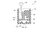
図4は、吐出ヘッド25の1つのノズル35近傍における部分断面図である。吐出ヘッド25は、開口31aを有する中空のケース31と、開口31aを塞ぐようにケース31に取り付けられた区画板32とを備えている。ケース31には、内部にインクが貯留される圧力室33が形成されている。区画板32は圧力室33の一部を区画している。区画板32は、圧力室33の内側および外側に弾性変形可能なものである。区画板32は、圧力室33の容積を増加および減少させるように変形可能に構成されている。区画板32は、典型的には樹脂フィルムである。
FIG. 4 is a partial cross-sectional view in the vicinity of one
ケース31の側壁には、インクが流入するインク流入口34が形成されている。なお、インク流入口34は圧力室33とつながっていればよく、インク流入口34の位置は何ら限定されない。圧力室33には、インク流入口34を通じてインクカートリッジ21からインクが供給され、一時的に所定量のインクが貯留される。ノズル35は、ケース31の下面31bに形成されている。ノズル35は、圧力室33と連通している。ノズル35は記録紙5に向かって液滴(インク滴)を吐出する。ノズル35内部のインクの液面(自由表面)がメニスカス35aを形成している。
An
圧力室33は、ヘルムホルツ固有振動周期Tcを有している。ヘルムホルツ固有振動周期Tcは、圧力室33を構成する各構成要素、例えばケース31や区画板32の材質や大きさ、形状、構成部材の配置位置、ノズル35の開口面積、インクの物性(例えば粘度)などによって一義的に特定される。ヘルムホルツ固有振動周期Tcは、インク吐出時の吐出ヘッド25に固有の振動周期である。ヘルムホルツ固有振動周期Tcは、例えば数μs〜数十μs程度(例えば6μs程度)の振動周期である。インク滴を吐出した後の圧力室33には、この振動周期をもった残留振動が生じることとなる。
The
区画板32の圧力室33側と反対側の面には、圧電素子36が連結されている。圧電素子36の一部は、ケース31に設けられた固定部材39に固定されている。圧電素子36は、アクチュエータを構成している。圧電素子36は、フレキシブルケーブル37を介して制御装置28に接続されている。圧電素子36には、フレキシブルケーブル37を介して電気信号が供給される。本実施形態において、圧電素子36は、圧電材料と導電層とを交互に積層した積層体である。圧電素子36は、制御装置28から電気信号を受けると膨張または収縮し、区画板32を圧力室33の外側または内側に弾性変形させるように機能する。ここでは、縦振動モードのピエゾ素子(PZT)を採用している。縦振動モードのPZTは、上記積層方向に伸縮自在であり、例えば放電すると収縮し、充電すると伸長するようになっている。ただし、圧電素子36の形式は特に限定されない。
A
このような構成の吐出ヘッド25では、例えば圧電素子36の電位を基準電位から下降させることによって、圧電素子36が収縮する。すると、これに追従して区画板32が初期位置から圧力室33の外側に弾性変形し、圧力室33が膨張する。なお、圧力室33が膨張するとは、区画板32の変形により圧力室33の容積が大きくなることをいう。次いで、圧電素子36の電位を上昇させることによって、圧電素子36が積層方向に伸長する。これにより、区画板32が圧力室33の内側に弾性変形し、圧力室33が収縮する。なお、圧力室33が収縮するとは、区画板32の変形により圧力室33の容積が小さくなることをいう。このような圧力室33の膨張および収縮により、圧力室33内の圧力が変動する。この圧力室33内の圧力変動によって、圧力室33内のインクが加圧され、インク滴となってノズル35から吐出される。その後、圧電素子36の電位を基準電位に戻すことにより、区画板32が初期位置に復帰して、圧力室33が膨張する。このとき、インク流入口34から圧力室33内にインクが流入する。
In the
制御装置28は、キャリッジ移動機構18のキャリッジモータ18aと、紙送り機構のフィードモータと、送液ポンプ23と、吐出ヘッド25とに対して、通信可能に接続されている。制御装置28は、これらの動作を制御する。制御装置28は、典型的にはコンピュータである。制御装置28は、例えば、ホストコンピュータ等の外部機器からの印刷データ等を受信するインターフェイス(I/F)と、制御プログラムの命令を実行する中央演算処理装置(CPU)と、CPUが実行するプログラムを格納したROMと、プログラムを展開するワーキングエリアとして使用されるRAMと、上記プログラムや各種データを格納するメモリなどの記憶装置とを備えている。
The
図3に示すように、制御装置28は、吐出ヘッド25を駆動するためのメイン駆動信号を生成する駆動信号生成回路41と、駆動信号生成回路41が生成するメイン駆動信号の一部または全部を吐出ヘッド25の各圧電素子36に供給する駆動信号供給回路42とを備えている。なお、以下の説明では、吐出ヘッド25の圧電素子36のことをアクチュエータ36と称する。駆動信号供給回路42がアクチュエータ36に供給する信号のことを、供給信号と称する。詳細は後述するが、供給信号は、駆動信号生成回路41が生成するメイン駆動信号の一部または全部からなる信号である。
As shown in FIG. 3, the
駆動信号生成回路41および駆動信号供給回路42のハードウェア構成は何ら限定されない。駆動信号生成回路41および駆動信号供給回路42のハードウェア構成には、周知のもの(例えば、特開2014−162221号公報に開示されたハードウェア構成)を利用することができるので、ここではその説明は省略する。
The hardware configuration of the drive
駆動信号生成回路41が生成するメイン駆動信号には、複数の駆動パルスが含まれる。詳細には、上記メイン駆動信号には、第1サブ駆動信号と、第2サブ駆動信号と、第3サブ駆動信号とが含まれる。第1サブ駆動信号、第2サブ駆動信号および第3サブ駆動信号は、それぞれ少なくとも1つの駆動パルスを含む。駆動信号供給回路42は、それら第1〜第3サブ駆動信号のうち1つまたは2つ以上のサブ駆動信号を選択し、アクチュエータ36に供給する。アクチュエータ36に供給するサブ駆動信号を適宜選択することにより、1駆動周期中に吐出ヘッド25のノズル35から吐出されるインクの液量を変更することができる。これにより、記録紙5上に形成されるインクのドットのサイズを変更することができる。本実施形態に係るプリンタ10では、サイズの異なる3種類のドットを形成することができる。以下の説明ではこれら3種類のドットのことを、サイズの小さい方から順に、第1ドット(小ドット)、第2ドット(中ドット)、第3ドット(大ドット)と称することとする。例えば、小ドットはインク質量が凡そ8ng〜凡そ10ngであり、中ドットはインク質量が凡そ12ng〜凡そ16ngであり、大ドットはインク質量が凡そ20ng〜凡そ24ngである。
The main drive signal generated by the drive
図3に示すように、駆動信号供給回路42は、第1ドット形成部42a、第2ドット形成部42bおよび第3ドット形成部42cを有している。駆動信号供給回路42は、第1ドットを形成するときに、アクチュエータ36に対して上記メイン駆動信号の一部である第1サブ駆動信号および第2サブ駆動信号を供給せずかつ上記メイン駆動信号の他の一部である第3サブ駆動信号を供給する第1ドット形成部42aとして機能する。駆動信号供給回路42は、第2ドットを形成するときに、アクチュエータ36に対して第1サブ駆動信号を供給せずかつ第2サブ駆動信号および第3サブ駆動信号を供給する第2ドット形成部42bとして機能する。駆動信号供給回路42は、第3ドットを形成するときに、アクチュエータ36に対して第1サブ駆動信号、第2サブ駆動信号および第3サブ駆動信号を供給する第3ドット形成部42cとして機能する。
As shown in FIG. 3, the drive
図5は、駆動信号生成回路41が生成するメイン駆動信号Wの波形図である。横軸tは時間を表し、縦軸Vは電位を表す。txは1駆動周期を表す。駆動信号生成回路41は、図5に示すようなメイン駆動信号Wを駆動周期毎に繰り返し生成するように構成されている。
FIG. 5 is a waveform diagram of the main drive signal W generated by the drive
図5に示すように、メイン駆動信号Wは、第1サブ駆動信号W1と、第2サブ駆動信号W2と、第3サブ駆動信号W3とを有する。第3サブ駆動信号W3は、メイン駆動信号Wの最後部に位置する。第2サブ駆動信号W2は、第1サブ駆動信号W1の後方に位置する。第3サブ駆動信号W3は、第2サブ駆動信号W2の後方に位置する。 As shown in FIG. 5, the main drive signal W includes a first sub drive signal W1, a second sub drive signal W2, and a third sub drive signal W3. The third sub drive signal W3 is located at the end of the main drive signal W. The second sub drive signal W2 is located behind the first sub drive signal W1. The third sub drive signal W3 is located behind the second sub drive signal W2.
第1サブ駆動信号W1は、第1駆動パルスP1および第5駆動パルスP5を含む。第5駆動パルスP5は第1駆動パルスP1の前方に位置する。第5駆動パルスP5は、電位がV0からV1に降下する放電波形要素T51と、電位がV1に維持される放電維持波形要素T52と、電位がV1からV0に上昇する充電波形要素T53とからなっている。第1駆動パルスP1は、電位がV0からV4に降下する放電波形要素T11と、電位がV4に維持される放電維持波形要素T12と、電位がV4からVmに上昇する充電波形要素T13と、電位がVmに維持される放電維持波形要素T14と、電位がVmからV0に上昇する充電波形要素T15とからなっている。 The first sub drive signal W1 includes a first drive pulse P1 and a fifth drive pulse P5. The fifth drive pulse P5 is located in front of the first drive pulse P1. The fifth drive pulse P5 includes a discharge waveform element T51 whose potential drops from V0 to V1, a discharge sustaining waveform element T52 whose potential is maintained at V1, and a charge waveform element T53 whose potential rises from V1 to V0. ing. The first drive pulse P1 includes a discharge waveform element T11 whose potential falls from V0 to V4, a discharge sustaining waveform element T12 whose potential is maintained at V4, a charge waveform element T13 whose potential rises from V4 to Vm, and a potential The discharge sustaining waveform element T14 is maintained at Vm, and the charging waveform element T15 whose potential rises from Vm to V0.
第2サブ駆動信号W2は、第2駆動パルスP2を含む。第2駆動パルスP2は、電位がV0からV2に降下する放電波形要素T21と、電位がV2に維持される放電維持波形要素T22と、電位がV2からV0に上昇する充電波形要素T23とからなっている。 The second sub drive signal W2 includes a second drive pulse P2. The second drive pulse P2 includes a discharge waveform element T21 whose potential drops from V0 to V2, a discharge sustaining waveform element T22 whose potential is maintained at V2, and a charge waveform element T23 whose potential rises from V2 to V0. ing.
第3サブ駆動信号W3は、第3駆動パルスP3および第4駆動パルスP4を含む。第3駆動パルスP3は第4駆動パルスP4より前に位置する。第3駆動パルスP3は、電位がV0からV1に降下する放電波形要素T31と、電位がV1に維持される放電維持波形要素T32と、電位がV1からV0に上昇する充電波形要素T33とからなっている。第4駆動パルスP4は、電位がV0からV3に降下する放電波形要素T41と、電位がV3に維持される放電維持波形要素T42と、電位がV3からV5に上昇する充電波形要素T43と、電位がV5に維持される充電維持波形要素T44と、電位がV5からV0に降下する放電波形要素T45とからなっている。なお、本実施形態では、V5>V0>Vm>V1>V2>V3>V4である。ただし、Vm、V1、V2、V3およびV4の相互の大小関係は特に限定されない。 The third sub drive signal W3 includes a third drive pulse P3 and a fourth drive pulse P4. The third drive pulse P3 is positioned before the fourth drive pulse P4. The third driving pulse P3 includes a discharge waveform element T31 whose potential drops from V0 to V1, a discharge sustaining waveform element T32 whose potential is maintained at V1, and a charge waveform element T33 whose potential rises from V1 to V0. ing. The fourth drive pulse P4 has a discharge waveform element T41 whose potential drops from V0 to V3, a discharge sustaining waveform element T42 whose potential is maintained at V3, a charge waveform element T43 whose potential rises from V3 to V5, and a potential Is maintained at V5, and a discharge waveform element T45 whose potential drops from V5 to V0. In the present embodiment, V5> V0> Vm> V1> V2> V3> V4. However, the mutual magnitude relationship between Vm, V1, V2, V3 and V4 is not particularly limited.
第1駆動パルスP1、第2駆動パルスP2、第3駆動パルスP3、第4駆動パルスP4および第5駆動パルスP5は、圧力室33の容積をいったん増加させてから減少させる(圧力室33をいったん膨張させてから収縮させる)駆動パルスである。言い換えると、第1駆動パルスP1〜第5駆動パルスP5は、圧力室33をいったん減圧させてから加圧させる駆動パルスである。第1駆動パルスP1〜第5駆動パルスP5は、それぞれ第1の液滴〜第5の液滴を吐出するための駆動パルスである。
The first drive pulse P1, the second drive pulse P2, the third drive pulse P3, the fourth drive pulse P4, and the fifth drive pulse P5 temporarily increase and then decrease the volume of the pressure chamber 33 (the
本実施形態では、第3駆動パルスP3の駆動の開始タイミングΔT1が、第2駆動パルスP2の開始からp×Tc(pは2より大きい値)後に設定されている。図6に示すように、1Tc<ΔT1<2Tcの領域では、Tcの変動に対して吐出量の変動が大きい。このため、予め設定したΔT1が液体吐出装置20の作動状況によって変動した場合(例えば、設定したΔT1に対して0.5μs〜1μs程度前後にずれた場合)に、吐出量のバラツキが大きくなってしまう。また、ΔT1=1TcまたはΔT1=2Tcのときには、吐出量が極大値をとるが、安定吐出の電圧マージンを確保することが困難である。一方、2Tc<ΔT1の領域では、Tcの変動に対して吐出量の変動が比較的小さい。このため、吐出量のバラツキを抑制することができる。上記pは、例えば、2より大きく2.5より小さいとよい。これにより、メイン駆動信号Wの全体の波形長を短くすることができるため、駆動周波数を高めることができ、高速印刷を実現することができる。また、上記pは、例えば、2.25より大きく2.75より小さいとよい。2.25Tc<ΔT1<2.75Tcの領域では、Tcの変動に対して吐出量の変動が特に小さいため、予め設定したΔT1が液体吐出装置20の作動状況によって変動したとしても、吐出量のバラツキをより抑制することができる。なお、本明細書において「p×Tc」とは、理論上のp×Tcに厳密に一致する場合に限らず、Tcの揺らぎや誤差などを許容し得るものである。例えば、「p×Tc」は、理論上のp×Tc−(1/6)×Tc〜p×Tc+(1/6)×Tcの範囲内の値であってよく、好ましくは理論上のp×Tc−(1/10)×Tc〜p×Tc+(1/10)×Tcの範囲内の値である。なお、図6に示す例は、ヘルムホルツ固有振動周期Tc=6μsの吐出ヘッドを備えたプリンタがΔT1として、0.83Tc、1.00Tc、1.17Tc、1.33Tc、1.50Tc、1.67Tc、1.83Tc、2.00Tc、2.17Tc、2.21Tc、2.25Tc、2.29Tc、2.33Tc、2.42Tc、2.50Tc、2.58Tc、2.67Tc、2.83Tc、3.00Tcの各時間において、第2ドット(中ドット)を形成するときのノズルから吐出されるインク量(吐出量:n/g)とインク吐出速度(吐出速度:m/s)との関係を示したグラフである。
In the present embodiment, the drive start timing ΔT1 of the third drive pulse P3 is set after p × Tc (p is a value larger than 2) from the start of the second drive pulse P2. As shown in FIG. 6, in the region of 1Tc <ΔT1 <2Tc, the fluctuation of the ejection amount is large relative to the fluctuation of Tc. For this reason, when the preset ΔT1 fluctuates depending on the operating condition of the liquid ejection device 20 (for example, when it is deviated by about 0.5 μs to 1 μs with respect to the set ΔT1), the variation of the discharge amount becomes large I will. In addition, when ΔT1 = 1Tc or ΔT1 = 2Tc, the discharge amount has a maximum value, but it is difficult to secure a voltage margin for stable discharge. On the other hand, in the region of 2Tc <ΔT1, the fluctuation of the ejection amount is relatively small with respect to the fluctuation of Tc. For this reason, the variation in the discharge amount can be suppressed. The p may be, for example, greater than 2 and less than 2.5. Thus, the entire waveform length of the main drive signal W can be shortened, so that the drive frequency can be increased, and high speed printing can be realized. Also, the above p may be, for example, greater than 2.25 and less than 2.75. In the region of 2.25Tc <ΔT1 <2.75Tc, the fluctuation of the ejection amount is particularly small with respect to the fluctuation of Tc, so even if ΔT1 set in advance fluctuates depending on the operating condition of the
第2駆動パルスP2の充電波形要素T23における電位の変化量ΔV2(V0−V2)は、第3駆動パルスP3の充電波形要素T33における電位の変化量ΔV3(V0−V1)と同じかそれよりも大きく設定されている。これにより、第3の液滴は、第2の液滴と同等かそれ以下のスピードで吐出されるようになっている。本実施形態では、(V0−V2)=1.2(V0−V1)程度に設定され、第2の液滴が第3の液滴の概ね1.2倍程度のスピードで吐出されるようになっている。特に限定されないが、メニスカス35aの振動を小さく抑える観点からは、(V0−V2)が概ね(V0−V1)の2倍以下であるとよい。
The amount of change in potential ΔV2 (V0-V2) of the charging waveform element T23 of the second drive pulse P2 is the same as or more than the amount of change ΔV3 (V0-V1) of the potential in the charging waveform element T33 of the third drive pulse P3. It is set large. Thereby, the third droplet is ejected at a speed equal to or less than that of the second droplet. In the present embodiment, (V0−V2) = 1.2 (V0−V1) or so is set so that the second droplet is ejected at approximately 1.2 times the speed of the third droplet. It has become. Although not particularly limited, it is preferable that (V0-V2) is approximately twice or less of (V0-V1) from the viewpoint of suppressing the vibration of the
本実施形態では、第1駆動パルスP1、第2駆動パルスP2、第3駆動パルスP3、第4駆動パルスP4および第5駆動パルスP5の放電時間(即ち放電と放電維持の合計時間)が、それぞれ、吐出ヘッド25のヘルムホルツ固有振動周期Tcの1/2に設定されている。即ち、図5に示すように、放電波形要素T51の開始時間をt1とし、放電維持波形要素T52の終了時間をt2としたときに、t1とt2とは、次式(1):t2−t1=(1/2)×Tc;を満たすように設定されている。放電波形要素T11の開始時間をt3とし、放電維持波形要素T12の終了時間をt4としたときに、t3とt4とは、次式(2):t4−t3=(1/2)×Tc;を満たすように設定されている。放電波形要素T21の開始時間をt5とし、放電維持波形要素T22の終了時間をt6としたときに、t6とt5とは、次式(3):t6−t5=(1/2)×Tc;を満たすように設定されている。放電波形要素T31の開始時間をt7とし、放電維持波形要素T32の終了時間をt8としたときに、t7とt8とは、次式(4):t8−t7=(1/2)×Tc;を満たすように設定されている。放電波形要素T41の開始時間をt9とし、放電維持波形要素T42の終了時間をt10としたときに、t9とt10とは、次式(5):t10−t9=(1/2)×Tc;を満たすように設定されている。このように、第1駆動パルスP1〜第5駆動パルスP5は、圧力室33の膨張している状態が(1/2)×Tcの時間持続されるように構成されている。
In the present embodiment, the discharge time of the first drive pulse P1, the second drive pulse P2, the third drive pulse P3, the fourth drive pulse P4, and the fifth drive pulse P5 (that is, the total time of discharge and discharge maintenance) is each And 1/2 of the Helmholtz natural vibration period Tc of the
図7Aに示すように、アクチュエータ36は、放電によって電圧値が下降すると収縮し、充電によって電圧値が上昇すると伸長する。圧力室33は、アクチュエータ36が収縮すると膨張し、アクチュエータ36が伸長すると収縮する。このため、上記式(1)におけるt2−t1、上記式(2)におけるt4−t3、上記式(3)におけるt6−t5、上記式(4)におけるt8−t7および上記式(5)におけるt10−t9は、圧力室33の膨張状態を維持する時間を表している。アクチュエータ36の収縮によって、圧力室33には、図7Bに破線で示すようなヘルムホルツ固有振動周期Tcのヘルムホルツ固有振動が生じる。ここで、上記式(1)〜式(5)を満たすタイミングでアクチュエータ36を収縮状態から伸長状態へと切り替えることにより、図7Bに実線で示すように、圧力室33のヘルムホルツ固有振動の振幅を増大させることができる。このように圧力室33の膨張収縮をヘルムホルツ固有振動に同期させることで、インク吐出を安定化させると共に、より小さい駆動電圧で相対的に大きなインク滴を吐出することができる。その結果、記録紙5上に大きなドットを精度よく形成することができる。
As shown in FIG. 7A, the
本実施形態では、第4駆動パルスP4の駆動の開始タイミングΔT2が、第3駆動パルスP3の開始からn×Tc(n≧2)後に設定されている。即ち、ヘルムホルツ固有振動周期Tcで振動している圧力室33が膨張し始めるタイミングで第4駆動パルスP4を開始する。これにより、ヘルムホルツ固有振動周期Tcで膨張している圧力室33の振動を打ち消す(キャンセルする)動作が防止され、吐出安定性を向上することができる。その結果、記録紙5上の所定の位置に安定した大きさのドットを形成することができる。なお、本明細書において「n×Tc」とは、理論上のn×Tcに厳密に一致する場合に限らず、Tcの揺らぎや誤差などを許容し得るものである。例えば、「n×Tc」は、理論上のn×Tc−(1/6)×Tc〜n×Tc+(1/6)×Tcの範囲内の値であってよく、好ましくは理論上のn×Tc−(1/10)×Tc〜n×Tc+(1/10)×Tcの範囲内の値である。
In the present embodiment, the drive start timing ΔT2 of the fourth drive pulse P4 is set n × Tc (n ≧ 2) after the start of the third drive pulse P3. That is, the fourth drive pulse P4 is started at the timing when the
ここで、上記第4駆動パルスP4の開始のタイミングを、第3駆動パルスP3の開始から2Tc以降、つまり、n≧2とする効果について説明する。第3の液滴を吐出した後の圧力室33には、アクチュエータ36の圧力変動が残留する。これにより、ノズル35のメニスカス35aは、圧力室33の側に大きく引き込まれた状態となる。メニスカス35aは、ノズル35の開口部の側へ継時的に回復し、上記引き込み量が少しずつ減少する。図7Cに示すように、メニスカス35aの引き込み量が大きなTc後の状態で第4駆動パルスP4を開始すると、第3の液滴吐出後から第4の液滴吐出開始までの時間間隔が短いため、所謂、引きうちの状態となり、第4の液滴の液量が少なくなってしまう。また、ノズル35近傍の流路抵抗が増大して、第4の液滴の吐出後にサテライトの速度が低下し易くなる。その結果、ミストが発生し易くなる。
Here, the effect of setting the timing of the start of the fourth drive pulse P4 to 2Tc or later from the start of the third drive pulse P3, that is,
第4駆動パルスP4の開始を2Tc以降(つまりn≧2)とすることで、メニスカス35aがノズル35の開口部の側に所定量以上回復した状態で、第4の液滴を吐出することができる。したがって、Tc経過後に第4駆動パルスP4を開始する場合と比べて、第4の液滴の液量を大きくすることができる。また、第3駆動パルスP3と第4駆動パルスP4との間隔が広がり、第3駆動パルスP3によって増大した圧力室33のヘルムホルツ振動が時間経過により収束してゆく。このため、圧力室33の収縮度合いが小さくなり、ノズル35を通過する単位時間当たりのインク量が減る。その結果、ノズル35近傍の流路抵抗も小さくなり、サテライトの速度を上昇させることができる。これにより、サテライト滴やミストの発生を抑制すると共に、第3の液滴と同等かそれ以上の吐出量で第4の液滴を安定的に吐出することができる。nの値は、例えば図1に示すような業務用の大判プリンタの場合にあっては、概ね10以下、典型的には7以下、好ましくは5以下、より好ましくは3以下、特にはn=2であるとよい。
By setting the start of the fourth driving pulse P4 to 2 Tc or later (that is, n ≧ 2), the fourth droplet can be discharged in a state where the
本実施形態では、第4駆動パルスP4によって吐出される第4の液滴が第3駆動パルスP3によって吐出される第3の液滴以上の速さになるように設定されている。即ち、第4駆動パルスP4の充電波形要素T43における電位の変化量(V5−V3)は、第3駆動パルスP3の充電波形要素T33における電位の変化量(V0−Vl)よりも大きく設定されている。これにより、第3の液滴と第4の液滴とを記録紙5上に着弾する前に(言い換えると飛翔中に)的確にマージさせることができる。また、長いサテライト滴やミストの発生をより良く抑制することもできる。 In the present embodiment, the fourth droplet ejected by the fourth drive pulse P4 is set to be faster than the third droplet ejected by the third drive pulse P3. That is, the amount of change in potential (V5-V3) of the charge waveform element T43 of the fourth drive pulse P4 is set larger than the amount of change (V0-Vl) of the potential in the charge waveform element T33 of the third drive pulse P3. There is. By this, it is possible to properly merge the third droplet and the fourth droplet before landing on the recording paper 5 (in other words, during the flight). In addition, the generation of long satellite droplets and mist can be better suppressed.
図8は、第1ドット(小ドット)を形成するときにアクチュエータ36に供給される供給信号を表している。アクチュエータ36に第3駆動パルスP3が供給されると、圧力室33の容積はいったん増加してから減少し、ノズル35から第3の液滴を吐出する動作が1回行われる。続いてアクチュエータ36に第4駆動パルスP4が供給されると、圧力室33の容積は、再びいったん増加してから減少し、ノズル35から第4の液滴を吐出する動作が1回行われる。すなわち、アクチュエータ36に第3駆動パルスP3および第4駆動パルスP4が供給されると、ノズル35から第3の液滴および第4の液滴を吐出する動作が行われる。第3の液滴と第4の液滴とは、記録紙5上に着弾する前にマージされる。
FIG. 8 shows the supply signal supplied to the
図9は、第2ドット(中ドット)を形成するときにアクチュエータ36に供給される供給信号を表している。アクチュエータ36に第2駆動パルスP2が供給されると、圧力室33の容積はいったん増加してから減少し、ノズル35から第2の液滴を吐出する動作が1回行われる。続いてアクチュエータ36に第3駆動パルスP3および第4駆動パルスP4が供給されると、圧力室33の容積は、再びいったん増加してから減少し、ノズル35から第3の液滴および第4の液滴を吐出する動作がそれぞれ1回行われる。すなわち、アクチュエータ36に第2駆動パルスP2〜第4駆動パルスP4が供給されると、ノズル35から第2の液滴〜第4の液滴を吐出する動作が行われる。第2の液滴〜第4の液滴は、記録紙5上に着弾する前にマージされる。
FIG. 9 shows the supply signal supplied to the
図10は、第3ドット(大ドット)を形成するときにアクチュエータ36に供給される供給信号を表している。アクチュエータ36に第5駆動パルスP5が供給されると、圧力室33の容積はいったん増加してから減少し、ノズル35から第5の液滴を吐出する動作が1回行われる。続いてアクチュエータ36に第1駆動パルスP1が供給されると、圧力室33の容積は、再びいったん増加してから減少し、ノズル35から第1の液滴を吐出する動作が1回行われる。さらに、アクチュエータ36に第2駆動パルスP2、第3駆動パルスP3および第4駆動パルスP4が供給されると、圧力室33の容積は、再びいったん増加してから減少し、ノズル35から第2の液滴、第3の液滴および第4の液滴を吐出する動作がそれぞれ1回行われる。すなわち、アクチュエータ36に第1駆動パルスP1〜第5駆動パルスP5が供給されると、ノズル35から第1の液滴〜第5の液滴を吐出する動作が行われる。第1の液滴〜第5の液滴は、記録紙5上に着弾する前にマージされる。
FIG. 10 shows the supply signal supplied to the
このように、プリンタ10では、第2ドットおよび第3ドットを形成するときに、第3駆動パルスP3の駆動の開始タイミングΔT1が、第2駆動パルスP2の開始からp×Tc(pは2より大きい値)後に設定されている。このため、液体吐出装置20の作動状況によって第3駆動パルスP3の駆動の開始タイミングがΔT1に対して前後するような場合であっても、インク吐出量のバラツキを抑制することができ、安定的に第2ドットおよび第3ドットを吐出することができる。
As described above, in the
以上のように、本実施形態の液体吐出装置20によると、第3駆動パルスP3は、第2駆動パルスP2の開始からΔT1(=p×Tc:pは2より大きい値である)後のタイミングで開始される。即ち、第3駆動パルスP3は、第2駆動パルスP2の開始から2Tcより遅いタイミングで開始される。ここで、2Tcより早いタイミングでは第2駆動パルスP2に基づいて第2液滴が吐出されたときに発生した振動が十分に減衰していないため、ノズル35から吐出される液滴の吐出量や吐出速度の変動が比較的大きい。一方、2Tcより遅いタイミングでは第2駆動パルスP2に基づいて第2液滴が吐出されたときに発生した振動が適度に減衰しているため、ノズル35から吐出される液滴の吐出量や吐出速度の変動が比較的小さい。このため、液体吐出装置20の作動状況によって、設定したΔT1に対して第3駆動パルスP3の開始のタイミングがわずかに前後することがあっても、ノズル35から吐出される液滴の吐出量や吐出速度の変動を小さく抑えることができる。このように、第3駆動パルスP3の開始のタイミングを2Tcより早いタイミングにした場合と比較して、所望の大きさの液滴(ここでは第2ドットおよび第3ドット)を安定的に吐出することができる。
As described above, according to the
また、第2ドットを形成する場合に加え、第3ドットを形成する場合にも安定吐出の電圧マージンを十分に確保することができる。より詳細には、第2ドットを形成する際には、第3駆動パルスP3の前に第2駆動パルスP2があるため、ΔT1=p×Tc(pは1以上の整数)のとき、第3の液滴は第2駆動パルスP2によって加速し、さらに加速した第3の液滴によって第4の液滴は第1ドットを形成するとき以上に加速する。ここで、pの値が小さいほど第3の液滴および第4の液滴の加速が大きくなる。このため、吐出速度や吐出量が増大し、吐出曲り等の不具合を誘発し得るメニスカス溢れが生じやすくなる(即ち電圧マージンも狭くなる)。上記不具合の発生を抑制するためには、ΔT1の値をできるだけ大きくすることが好ましく、波形長を考慮すると第2駆動パルスP2の振動が適度に減衰した2Tcより遅いタイミングがより好ましい。さらに、吐出量が増えるほど(即ち駆動パルスP2の前に位置する駆動パルスが増えるほど)メニスカス溢れの発生が起きやすくなる。このため、第2ドットを形成するときの安定吐出を実現するためにより広い電圧マージンを確保することによって、第3ドットを形成するときの吐出不安定の発生をより抑制することができる。 Further, in addition to the case of forming the second dot, the voltage margin for stable discharge can be sufficiently secured also in the case of forming the third dot. More specifically, since the second drive pulse P2 precedes the third drive pulse P3 when forming the second dot, the third operation is performed when ΔT1 = p × Tc (p is an integer of 1 or more). The droplet is accelerated by the second driving pulse P2, and the accelerated third droplet accelerates the fourth droplet more than when forming the first dot. Here, the smaller the value of p, the larger the acceleration of the third droplet and the fourth droplet. As a result, the ejection speed and the ejection amount increase, and it becomes easy to cause meniscus overflow that can cause problems such as ejection bending (that is, the voltage margin also becomes narrow). In order to suppress the occurrence of the above-mentioned failure, it is preferable to increase the value of ΔT1 as much as possible, and in consideration of the waveform length, it is more preferable to have a timing later than 2Tc where the vibration of the second drive pulse P2 is moderately attenuated. Furthermore, as the ejection amount increases (that is, as the drive pulse positioned before the drive pulse P2 increases), the occurrence of meniscus overflow is more likely to occur. Therefore, by securing a wider voltage margin to realize stable discharge when forming the second dot, it is possible to further suppress the occurrence of discharge instability when forming the third dot.
本実施形態の液体吐出装置20では、pは、2より大きく2.5より小さくてもよい。これにより、メイン駆動信号Wの全体の波形長を短くすることができるため、駆動周波数を高めることができ、高速印刷を実現することができる。
In the
本実施形態の液体吐出装置20では、pは、例えば、2.25より大きく2.75より小さくてもよい。2.25Tc<ΔT1<2.75Tcの領域では、Tcの変動に対して吐出量の変動が特に小さいため、予め設定したΔT1が液体吐出装置20の作動状況によって変化したとしても、吐出量のバラツキをより抑制することができる。
In the
本実施形態の液体吐出装置20では、第2駆動パルスP2の中間電位V0から第2最小電位V2までの電位の変化量をΔV2とし、第3駆動パルスP3の中間電位V0から第3最小電位V1までの電位の変化量をΔV3としたときに、ΔV2とΔV3とが、ΔV2≧ΔV3を満たすように構成されている。これにより、第3の液滴は、第2の液滴と同等かそれ以下のスピードで吐出される。これにより、第2ドットを形成する場合に加え、第3ドットを形成する場合にも安定吐出の電圧マージンをよりよく確保することができる。
In the
本実施形態の液体吐出装置20では、第3駆動パルスP3および第4駆動パルスP4において、圧力室33を(1/2)×Tcのタイミングで膨張状態から収縮に切り替える。これにより、第3駆動パルスP3および第4駆動パルスP4が、圧力室33のヘルムホルツ固有振動周期Tcを増幅させるように作用する。その結果、液滴の吐出安定性を高めると共に、圧力室33の膨張収縮量が増して、より大きな液滴を吐出することができる。また、液体吐出装置20では、第4駆動パルスP4の開始のタイミングを第3駆動パルスP3の開始からn×Tc(n≧2)後とする。これにより、第3の液滴吐出後のメニスカス35aの引き込み量が適度に低減され、液量の多い大きな第4の液滴を安定的に吐出することができる。さらに、液体吐出装置20では、第4の液滴が第3の液滴以上の速さで吐出される。このため、第3の液滴と第4の液滴とが的確にマージされる。また、第4の液滴の吐出速度が速められることで、サテライト滴やミストの発生を高度に抑制することができる。
In the
本実施形態の液体吐出装置20では、第1駆動パルスP1において、圧力室33を(1/2)×Tcのタイミングで膨張状態から収縮に切り替える。これにより、第1駆動パルスP1が、圧力室33のヘルムホルツ固有振動周期Tcを増幅させるように作用する。その結果、液滴の吐出安定性を高めると共に、圧力室33の膨張収縮量が増して、より大きな第1の液滴を吐出することができる。
In the
本実施形態の液体吐出装置20では、第2駆動パルスP2において、圧力室33を(1/2)×Tcのタイミングで膨張状態から収縮に切り替える。これにより、より大きな第2の液滴を吐出することができる。
In the
本実施形態の液体吐出装置20では、第5駆動パルスP5において、圧力室33を(1/2)×Tcのタイミングで膨張状態から収縮に切り替える。これにより、より大きな第5の液滴を吐出することができる。
In the
以上、本発明の好適な実施形態について説明した。しかし、上述の各実施形態は例示に過ぎず、本発明は他の種々の形態で実施することができる。 The preferred embodiment of the present invention has been described above. However, the above-described embodiments are merely illustrative, and the present invention can be embodied in other various forms.
上記した各実施形態では、アクチュエータ36は縦振動モードの圧電素子であったが、これには限定されない。アクチュエータ36は横振動モードの圧電素子であってもよい。また、アクチュエータ36は、圧電素子に限らず、例えば磁歪素子等であってもよい。
In each of the embodiments described above, the
上記した各実施形態では、液体がインクであったが、これには限定されない。液体吐出装置20が吐出する液体は、例えば樹脂材料や、溶質と溶媒とを含む各種液状組成物(例えば洗浄液)などであってもよい。
In each of the embodiments described above, the liquid is ink, but is not limited thereto. The liquid ejected by the
上記した実施形態では、吐出ヘッドがプリンタ10に搭載される吐出ヘッド25であったが、これには限定されない。吐出ヘッドは、例えばインクジェット方式を採用する種々の製造装置や、マイクロピペットなどの計測器具などに搭載することができ、各種用途で使用可能である。
Although the discharge head is the
上記した実施形態では、第1サブ駆動信号W1が2つの駆動パルスを含み、第2サブ駆動信号W2が1つの駆動信号を含み、第3サブ駆動信号W3が2つの駆動パルスを含んでいたがこれに限定されない。第1サブ駆動信号W1は1または3以上の駆動パルスを含んでいてもよいし、第2サブ駆動信号W2は2以上の駆動パルスを含んでいてもよいし、第3サブ駆動信号W3は1または3以上の駆動パルスを含んでいてもよい。 In the embodiment described above, the first sub drive signal W1 includes two drive pulses, the second sub drive signal W2 includes one drive signal, and the third sub drive signal W3 includes two drive pulses. It is not limited to this. The first sub drive signal W1 may include one or more drive pulses, the second sub drive signal W2 may include two or more drive pulses, and the third sub drive signal W3 may be one. Alternatively, three or more drive pulses may be included.
上記した実施形態では、メイン駆動信号Wは第1サブ駆動信号W1、第2サブ駆動信号W2および第3サブ駆動信号W3を有していたが、これに限定されない。メイン駆動信号Wは、2つのサブ駆動信号のみを有していてもよいし、4以上のサブ駆動信号を有していてもよい。 In the above-described embodiment, the main drive signal W includes the first sub drive signal W1, the second sub drive signal W2, and the third sub drive signal W3. However, the present invention is not limited to this. The main drive signal W may have only two sub drive signals or may have four or more sub drive signals.
10 プリンタ(インクジェットプリンタ)
20 液体吐出装置
25 吐出ヘッド(液体吐出ヘッド)
28 制御装置
32 区画板
33 圧力室
35 ノズル
36 圧電素子(アクチュエータ)
41 駆動信号生成回路
42 駆動信号供給回路
42a 第1ドット形成部
42b 第2ドット形成部
42c 第3ドット形成部
10 Printer (ink jet printer)
20
28
41 Drive
Claims (8)
前記液体吐出ヘッドを制御する制御装置と、を備え、
前記液体吐出ヘッドは、
内部に液体が貯留される圧力室が形成されたケースと、
前記ケースに設けられ、前記圧力室の一部を区画する区画板と、
前記区画板に連結され、電気信号が供給されると変形するアクチュエータと、
前記ケースに形成され、前記圧力室と連通するノズルと、を備え、
前記制御装置は、
駆動周期毎に、前記圧力室を膨張および収縮させることにより第1の液滴を吐出するための第1駆動パルスを含む第1サブ駆動信号と、前記圧力室を膨張および収縮させることにより第2の液滴を吐出するための第2駆動パルスを含む第2サブ駆動信号と、前記圧力室を膨張および収縮させることにより第3の液滴を吐出するための第3駆動パルスを含み、前記第2サブ駆動信号の後方に位置する第3サブ駆動信号と、を有するメイン駆動信号を生成する駆動信号生成回路と、
前記駆動信号生成回路が生成する前記メイン駆動信号の一部または全部を前記アクチュエータに供給する駆動信号供給回路と、を備え、
前記駆動信号供給回路は、
前記アクチュエータに対して前記第1サブ駆動信号および前記第2サブ駆動信号を供給せずかつ前記第3サブ駆動信号を供給する第1ドット形成部と、
前記アクチュエータに対して前記第1サブ駆動信号を供給せずかつ前記第2サブ駆動信号および前記第3サブ駆動信号を供給する第2ドット形成部と、
前記アクチュエータに対して前記第1サブ駆動信号および前記第2サブ駆動信号および前記第3サブ駆動信号を供給する第3ドット形成部と、を備え、
前記液体吐出ヘッドのヘルムホルツ固有振動周期をTcとしたときに、
前記第3駆動パルスは、前記第2駆動パルスの開始からp×Tc(ただし、pは2.25より大きく2.75より小さい値である。)後のタイミングで開始される、液体吐出装置。 A liquid discharge head for discharging a liquid;
A controller for controlling the liquid discharge head;
The liquid discharge head is
A case in which a pressure chamber in which liquid is stored is formed;
A partition plate provided in the case and partitioning a part of the pressure chamber;
An actuator connected to the partition plate and deformed when an electrical signal is supplied;
A nozzle formed in the case and in communication with the pressure chamber;
The controller is
A second sub drive signal including a first drive pulse for discharging a first droplet by expanding and contracting the pressure chamber for each drive cycle, and a second sub-drive signal by expanding and contracting the pressure chamber. A second sub-driving signal including a second driving pulse for discharging a second liquid droplet, and a third driving pulse for discharging a third liquid droplet by expanding and contracting the pressure chamber; A drive signal generation circuit generating a main drive signal having a third sub drive signal located behind the two sub drive signals;
And a drive signal supply circuit for supplying a part or all of the main drive signal generated by the drive signal generation circuit to the actuator.
The drive signal supply circuit
A first dot formation unit that supplies the third sub drive signal without supplying the first sub drive signal and the second sub drive signal to the actuator;
A second dot forming unit that does not supply the first sub drive signal to the actuator and supplies the second sub drive signal and the third sub drive signal;
And a third dot forming unit for supplying the first sub-driving signal and the second sub-driving signal and the third sub-drive signal to the actuator,
When the Helmholtz natural vibration period of the liquid discharge head is Tc,
The liquid discharge device, wherein the third drive pulse is started at a timing after p × Tc (where p is a value larger than 2.25 and smaller than 2.75 ) from the start of the second drive pulse.
前記液体吐出ヘッドを制御する制御装置と、を備え、
前記液体吐出ヘッドは、
内部に液体が貯留される圧力室が形成されたケースと、
前記ケースに設けられ、前記圧力室の一部を区画する区画板と、
前記区画板に連結され、電気信号が供給されると変形するアクチュエータと、
前記ケースに形成され、前記圧力室と連通するノズルと、を備え、
前記制御装置は、
駆動周期毎に、前記圧力室を膨張および収縮させることにより第1の液滴を吐出するための第1駆動パルスを含む第1サブ駆動信号と、前記圧力室を膨張および収縮させることにより第2の液滴を吐出するための第2駆動パルスを含む第2サブ駆動信号と、前記圧力室を膨張および収縮させることにより第3の液滴を吐出するための第3駆動パルスを含み、前記第2サブ駆動信号の後方に位置する第3サブ駆動信号と、を有するメイン駆動信号を生成する駆動信号生成回路と、
前記駆動信号生成回路が生成する前記メイン駆動信号の一部または全部を前記アクチュエータに供給する駆動信号供給回路と、を備え、
前記駆動信号供給回路は、
前記アクチュエータに対して前記第1サブ駆動信号および前記第2サブ駆動信号を供給せずかつ前記第3サブ駆動信号を供給する第1ドット形成部と、
前記アクチュエータに対して前記第1サブ駆動信号を供給せずかつ前記第2サブ駆動信号および前記第3サブ駆動信号を供給する第2ドット形成部と、
前記アクチュエータに対して前記第1サブ駆動信号および前記第2サブ駆動信号および前記第3サブ駆動信号を供給する第3ドット形成部と、を備え、
前記液体吐出ヘッドのヘルムホルツ固有振動周期をTcとしたときに、
前記第3駆動パルスは、前記第2駆動パルスの開始からp×Tc(ただし、pは2より大きい値である。)後のタイミングで開始され、
前記第1駆動パルスは、第1の時間の間に中間電位から第1最小電位まで下降する第1電位下降波形を含み、
前記第2駆動パルスは、第2の時間の間に中間電位から第2最小電位まで下降する第2電位下降波形を含み、
前記第3駆動パルスは、第3の時間の間に中間電位から第3最小電位まで下降する第3電位下降波形を含み、
前記第2駆動パルスの前記中間電位から前記第2最小電位までの電位の変化量をΔV2とし、前記第3駆動パルスの前記中間電位から前記第3最小電位までの電位の変化量をΔV3としたときに、前記ΔV2と前記ΔV3とが、ΔV2≧ΔV3を満たすように構成されている、液体吐出装置。 A liquid discharge head for discharging a liquid;
A controller for controlling the liquid discharge head;
The liquid discharge head is
A case in which a pressure chamber in which liquid is stored is formed;
A partition plate provided in the case and partitioning a part of the pressure chamber;
An actuator connected to the partition plate and deformed when an electrical signal is supplied;
A nozzle formed in the case and in communication with the pressure chamber;
The controller is
A second sub drive signal including a first drive pulse for discharging a first droplet by expanding and contracting the pressure chamber for each drive cycle, and a second sub-drive signal by expanding and contracting the pressure chamber. A second sub-driving signal including a second driving pulse for discharging a second liquid droplet, and a third driving pulse for discharging a third liquid droplet by expanding and contracting the pressure chamber; A drive signal generation circuit generating a main drive signal having a third sub drive signal located behind the two sub drive signals;
And a drive signal supply circuit for supplying a part or all of the main drive signal generated by the drive signal generation circuit to the actuator.
The drive signal supply circuit
A first dot formation unit that supplies the third sub drive signal without supplying the first sub drive signal and the second sub drive signal to the actuator;
A second dot forming unit that does not supply the first sub drive signal to the actuator and supplies the second sub drive signal and the third sub drive signal;
And a third dot formation unit that supplies the first sub drive signal, the second sub drive signal, and the third sub drive signal to the actuator.
When the Helmholtz natural vibration period of the liquid discharge head is Tc,
The third drive pulse is started at a timing after p × Tc (where p is a value larger than 2) from the start of the second drive pulse,
The first drive pulse includes a first potential falling waveform which falls from an intermediate potential to a first minimum potential during a first time,
The second drive pulse includes a second potential falling waveform which falls from an intermediate potential to a second minimum potential during a second time,
The third drive pulse includes a third potential falling waveform which falls from an intermediate potential to a third minimum potential during a third time,
The amount of change in potential from the intermediate potential to the second minimum potential of the second drive pulse is ΔV2, and the amount of change in potential from the intermediate potential of the third drive pulse to the third minimum potential is ΔV3 Occasionally, the [Delta] V2 and said .DELTA.V3 is configured so as to satisfy the [Delta] V2 ≧ .DELTA.V3, liquid-dispensing device.
前記第3駆動パルスは、前記第3最小電位を所定の時間維持する第3最小電位維持波形と、前記第3最小電位から前記中間電位まで上昇する第3電位復帰波形をさらに含む、請求項2に記載の液体吐出装置。 The second drive pulse further includes a second minimum potential maintaining waveform for maintaining the second minimum potential for a predetermined time, and a second potential return waveform for rising from the second minimum potential to the intermediate potential,
The third drive pulse further comprises a third potential minimum maintenance waveform for maintaining the third potential minimum predetermined time, the third potential return waveform rising from the third minimum potential to the intermediate potential, according to claim 2 The liquid ejection device according to claim 1.
前記液体吐出ヘッドを制御する制御装置と、を備え、
前記液体吐出ヘッドは、
内部に液体が貯留される圧力室が形成されたケースと、
前記ケースに設けられ、前記圧力室の一部を区画する区画板と、
前記区画板に連結され、電気信号が供給されると変形するアクチュエータと、
前記ケースに形成され、前記圧力室と連通するノズルと、を備え、
前記制御装置は、
駆動周期毎に、前記圧力室を膨張および収縮させることにより第1の液滴を吐出するための第1駆動パルスを含む第1サブ駆動信号と、前記圧力室を膨張および収縮させることにより第2の液滴を吐出するための第2駆動パルスを含む第2サブ駆動信号と、前記圧力室を膨張および収縮させることにより第3の液滴を吐出するための第3駆動パルスを含み、前記第2サブ駆動信号の後方に位置する第3サブ駆動信号と、を有するメイン駆動信号を生成する駆動信号生成回路と、
前記駆動信号生成回路が生成する前記メイン駆動信号の一部または全部を前記アクチュエータに供給する駆動信号供給回路と、を備え、
前記駆動信号供給回路は、
前記アクチュエータに対して前記第1サブ駆動信号および前記第2サブ駆動信号を供給せずかつ前記第3サブ駆動信号を供給する第1ドット形成部と、
前記アクチュエータに対して前記第1サブ駆動信号を供給せずかつ前記第2サブ駆動信号および前記第3サブ駆動信号を供給する第2ドット形成部と、
前記アクチュエータに対して前記第1サブ駆動信号および前記第2サブ駆動信号および前記第3サブ駆動信号を供給する第3ドット形成部と、を備え、
前記液体吐出ヘッドのヘルムホルツ固有振動周期をTcとしたときに、
前記第3駆動パルスは、前記第2駆動パルスの開始からp×Tc(ただし、pは2より大きい値である。)後のタイミングで開始され、
前記第3サブ駆動信号は、前記第3駆動パルスより後方に位置し、前記圧力室を膨張および収縮させることにより第4の液滴を吐出するための第4駆動パルスを含み、
前記第3駆動パルスは、前記圧力室の膨張している状態が(1/2)×Tcの時間持続されるように構成され、
前記第4駆動パルスは、前記第3駆動パルスの開始からn×Tc(ただし、nは2以上の整数である。)後のタイミングで開始され、前記圧力室の膨張している状態が(1/2)×Tcの時間持続され、前記第4の液滴が前記第3の液滴以上の速さで吐出されるように構成されている、液体吐出装置。 A liquid discharge head for discharging a liquid;
A controller for controlling the liquid discharge head;
The liquid discharge head is
A case in which a pressure chamber in which liquid is stored is formed;
A partition plate provided in the case and partitioning a part of the pressure chamber;
An actuator connected to the partition plate and deformed when an electrical signal is supplied;
A nozzle formed in the case and in communication with the pressure chamber;
The controller is
A second sub drive signal including a first drive pulse for discharging a first droplet by expanding and contracting the pressure chamber for each drive cycle, and a second sub-drive signal by expanding and contracting the pressure chamber. A second sub-driving signal including a second driving pulse for discharging a second liquid droplet, and a third driving pulse for discharging a third liquid droplet by expanding and contracting the pressure chamber; A drive signal generation circuit generating a main drive signal having a third sub drive signal located behind the two sub drive signals;
And a drive signal supply circuit for supplying a part or all of the main drive signal generated by the drive signal generation circuit to the actuator.
The drive signal supply circuit
A first dot formation unit that supplies the third sub drive signal without supplying the first sub drive signal and the second sub drive signal to the actuator;
A second dot forming unit that does not supply the first sub drive signal to the actuator and supplies the second sub drive signal and the third sub drive signal;
And a third dot formation unit that supplies the first sub drive signal, the second sub drive signal, and the third sub drive signal to the actuator.
When the Helmholtz natural vibration period of the liquid discharge head is Tc,
The third drive pulse is started at a timing after p × Tc (where p is a value larger than 2) from the start of the second drive pulse,
The third sub drive signal is positioned rearward of the third drive pulse, and includes a fourth drive pulse for discharging a fourth droplet by expanding and contracting the pressure chamber,
The third driving pulse is configured to maintain the expanded state of the pressure chamber for a time of (1/2) × Tc,
The fourth drive pulse is started at a timing after n × Tc (where n is an integer of 2 or more) from the start of the third drive pulse, and the pressure chamber is in an expanded state (1 / 2) × a duration of Tc, the fourth droplet is configured to be discharged by the third liquid drops faster than the liquid discharge device.
前記第5駆動パルスは、前記圧力室の膨張している状態が(1/2)×Tcの時間持続されるように構成されている、請求項1から6のいずれか一項に記載の液体吐出装置。 The first sub drive signal includes a fifth drive pulse for discharging a fifth droplet by expanding and contracting the pressure chamber,
The liquid according to any one of claims 1 to 6 , wherein the fifth drive pulse is configured such that the expanded state of the pressure chamber is sustained for a time of (1/2) x Tc. Discharge device.
Priority Applications (2)
| Application Number | Priority Date | Filing Date | Title |
|---|---|---|---|
| JP2017075040A JP6534412B2 (en) | 2017-04-05 | 2017-04-05 | Liquid ejection apparatus and ink jet printer equipped with the same |
| US15/922,950 US10214010B2 (en) | 2017-04-05 | 2018-03-16 | Liquid discharge device and inkjet printer including the same |
Applications Claiming Priority (1)
| Application Number | Priority Date | Filing Date | Title |
|---|---|---|---|
| JP2017075040A JP6534412B2 (en) | 2017-04-05 | 2017-04-05 | Liquid ejection apparatus and ink jet printer equipped with the same |
Publications (2)
| Publication Number | Publication Date |
|---|---|
| JP2018176457A JP2018176457A (en) | 2018-11-15 |
| JP6534412B2 true JP6534412B2 (en) | 2019-06-26 |
Family
ID=63709870
Family Applications (1)
| Application Number | Title | Priority Date | Filing Date |
|---|---|---|---|
| JP2017075040A Expired - Fee Related JP6534412B2 (en) | 2017-04-05 | 2017-04-05 | Liquid ejection apparatus and ink jet printer equipped with the same |
Country Status (2)
| Country | Link |
|---|---|
| US (1) | US10214010B2 (en) |
| JP (1) | JP6534412B2 (en) |
Families Citing this family (2)
| Publication number | Priority date | Publication date | Assignee | Title |
|---|---|---|---|---|
| DE112017005559T5 (en) * | 2016-12-02 | 2019-07-18 | Fujifilm Corporation | Image recording apparatus and method |
| WO2020202245A1 (en) | 2019-03-29 | 2020-10-08 | コニカミノルタ株式会社 | Method of driving inkjet head, and inkjet recording device |
Family Cites Families (8)
| Publication number | Priority date | Publication date | Assignee | Title |
|---|---|---|---|---|
| JP3264422B2 (en) | 1996-09-09 | 2002-03-11 | セイコーエプソン株式会社 | Driving apparatus and driving method for inkjet print head |
| US6488349B1 (en) * | 1999-09-21 | 2002-12-03 | Matsushita Electric Industrial Co., Ltd. | Ink-jet head and ink-jet type recording apparatus |
| US7988247B2 (en) * | 2007-01-11 | 2011-08-02 | Fujifilm Dimatix, Inc. | Ejection of drops having variable drop size from an ink jet printer |
| US8353567B1 (en) * | 2010-09-08 | 2013-01-15 | Hewlett-Packard Development Company, L.P. | Drive waveform generation |
| JP5334271B2 (en) * | 2011-06-03 | 2013-11-06 | 富士フイルム株式会社 | Liquid ejection head drive device, liquid ejection device, and ink jet recording apparatus |
| JP5905806B2 (en) * | 2012-09-24 | 2016-04-20 | 富士フイルム株式会社 | Method for driving liquid discharge head and image forming apparatus |
| JP6079301B2 (en) | 2013-02-28 | 2017-02-15 | 株式会社リコー | Image forming apparatus and head drive control method |
| JP6005616B2 (en) * | 2013-09-30 | 2016-10-12 | 富士フイルム株式会社 | Inkjet head correction method and inkjet recording apparatus |
-
2017
- 2017-04-05 JP JP2017075040A patent/JP6534412B2/en not_active Expired - Fee Related
-
2018
- 2018-03-16 US US15/922,950 patent/US10214010B2/en not_active Expired - Fee Related
Also Published As
| Publication number | Publication date |
|---|---|
| JP2018176457A (en) | 2018-11-15 |
| US20180290445A1 (en) | 2018-10-11 |
| US10214010B2 (en) | 2019-02-26 |
Similar Documents
| Publication | Publication Date | Title |
|---|---|---|
| JP6644537B2 (en) | Liquid ejection device and ink jet recording device provided with the same | |
| JP4321563B2 (en) | Liquid ejecting apparatus and method for controlling liquid ejecting apparatus | |
| JP2014019050A (en) | Ink jet recording device and method for driving ink jet recording head | |
| JP6764237B2 (en) | How to generate a drive signal for a liquid discharge device | |
| JP6644538B2 (en) | Liquid ejection device and ink jet recording device provided with the same | |
| JP4257547B2 (en) | Manufacturing method and driving method of liquid jet head | |
| JP6534412B2 (en) | Liquid ejection apparatus and ink jet printer equipped with the same | |
| JP2020044666A (en) | Liquid ejection head, liquid ejection recording apparatus, and drive signal generation system | |
| JP2019084782A (en) | Liquid discharge device and ink jet printer equipped with the same | |
| JP2010167724A (en) | Liquid jetting apparatus | |
| JP2013248750A (en) | Liquid ejecting apparatus, and control method of the same | |
| JP6660234B2 (en) | Liquid ejection device and ink jet recording device provided with the same | |
| JP2011088346A (en) | Liquid jet apparatus, and method for controlling liquid jet apparatus | |
| JP6542274B2 (en) | Liquid ejection apparatus and ink jet printer equipped with the same | |
| JP2014188713A (en) | Liquid jet device | |
| JP7184670B2 (en) | LIQUID EJECTOR AND INKJET PRINTER INCLUDING THE SAME | |
| JP2020023058A (en) | LIQUID DISCHARGE DEVICE AND INK JET PRINTER HAVING THE SAME | |
| JP2020082433A (en) | Liquid discharge device and ink jet printer equipped therewith | |
| JP6855107B2 (en) | Liquid discharge device and inkjet printer equipped with it | |
| US10449761B2 (en) | Liquid ejection device and inkjet printer including the same | |
| JP6540302B2 (en) | Ink jet recording apparatus and ink jet recording method | |
| JP6051610B2 (en) | Liquid ejecting apparatus and method for controlling liquid ejecting apparatus | |
| JP2020001332A (en) | Liquid injection head, liquid injection recording device and drive method of liquid injection head | |
| JP2018083389A (en) | Liquid ejecting apparatus and inkjet printer provided with the same | |
| JP2025149676A (en) | Liquid ejection device and method for driving the liquid ejection device |
Legal Events
| Date | Code | Title | Description |
|---|---|---|---|
| A131 | Notification of reasons for refusal |
Free format text: JAPANESE INTERMEDIATE CODE: A131 Effective date: 20181127 |
|
| A521 | Request for written amendment filed |
Free format text: JAPANESE INTERMEDIATE CODE: A523 Effective date: 20190122 |
|
| TRDD | Decision of grant or rejection written | ||
| A01 | Written decision to grant a patent or to grant a registration (utility model) |
Free format text: JAPANESE INTERMEDIATE CODE: A01 Effective date: 20190528 |
|
| A61 | First payment of annual fees (during grant procedure) |
Free format text: JAPANESE INTERMEDIATE CODE: A61 Effective date: 20190528 |
|
| R150 | Certificate of patent or registration of utility model |
Ref document number: 6534412 Country of ref document: JP Free format text: JAPANESE INTERMEDIATE CODE: R150 |
|
| LAPS | Cancellation because of no payment of annual fees |