JP6533643B2 - Microprocessor and electronic device using the same - Google Patents
Microprocessor and electronic device using the same Download PDFInfo
- Publication number
- JP6533643B2 JP6533643B2 JP2014051308A JP2014051308A JP6533643B2 JP 6533643 B2 JP6533643 B2 JP 6533643B2 JP 2014051308 A JP2014051308 A JP 2014051308A JP 2014051308 A JP2014051308 A JP 2014051308A JP 6533643 B2 JP6533643 B2 JP 6533643B2
- Authority
- JP
- Japan
- Prior art keywords
- rename
- data
- renaming
- checkpoint
- rob
- Prior art date
- Legal status (The legal status is an assumption and is not a legal conclusion. Google has not performed a legal analysis and makes no representation as to the accuracy of the status listed.)
- Active
Links
- 230000003068 static effect Effects 0.000 claims description 37
- 238000004891 communication Methods 0.000 claims description 10
- 230000004044 response Effects 0.000 claims description 9
- 238000013507 mapping Methods 0.000 claims description 7
- 238000001514 detection method Methods 0.000 claims 1
- 238000010586 diagram Methods 0.000 description 17
- 238000000034 method Methods 0.000 description 11
- 101150073133 Cpt1a gene Proteins 0.000 description 10
- 230000008569 process Effects 0.000 description 5
- 230000008901 benefit Effects 0.000 description 3
- 230000007423 decrease Effects 0.000 description 3
- 230000001934 delay Effects 0.000 description 3
- 239000004065 semiconductor Substances 0.000 description 3
- 238000011010 flushing procedure Methods 0.000 description 2
- GWAOOGWHPITOEY-UHFFFAOYSA-N 1,5,2,4-dioxadithiane 2,2,4,4-tetraoxide Chemical compound O=S1(=O)CS(=O)(=O)OCO1 GWAOOGWHPITOEY-UHFFFAOYSA-N 0.000 description 1
- 238000013459 approach Methods 0.000 description 1
- 230000005540 biological transmission Effects 0.000 description 1
- 101150043789 cpt2 gene Proteins 0.000 description 1
- 238000012986 modification Methods 0.000 description 1
- 230000004048 modification Effects 0.000 description 1
- 238000012545 processing Methods 0.000 description 1
- 238000011084 recovery Methods 0.000 description 1
Images


Classifications
-
- G—PHYSICS
- G06—COMPUTING; CALCULATING OR COUNTING
- G06F—ELECTRIC DIGITAL DATA PROCESSING
- G06F9/00—Arrangements for program control, e.g. control units
- G06F9/06—Arrangements for program control, e.g. control units using stored programs, i.e. using an internal store of processing equipment to receive or retain programs
- G06F9/22—Microcontrol or microprogram arrangements
-
- G—PHYSICS
- G06—COMPUTING; CALCULATING OR COUNTING
- G06F—ELECTRIC DIGITAL DATA PROCESSING
- G06F9/00—Arrangements for program control, e.g. control units
- G06F9/06—Arrangements for program control, e.g. control units using stored programs, i.e. using an internal store of processing equipment to receive or retain programs
- G06F9/30—Arrangements for executing machine instructions, e.g. instruction decode
- G06F9/30098—Register arrangements
-
- G—PHYSICS
- G06—COMPUTING; CALCULATING OR COUNTING
- G06F—ELECTRIC DIGITAL DATA PROCESSING
- G06F9/00—Arrangements for program control, e.g. control units
- G06F9/06—Arrangements for program control, e.g. control units using stored programs, i.e. using an internal store of processing equipment to receive or retain programs
- G06F9/30—Arrangements for executing machine instructions, e.g. instruction decode
- G06F9/38—Concurrent instruction execution, e.g. pipeline or look ahead
- G06F9/3836—Instruction issuing, e.g. dynamic instruction scheduling or out of order instruction execution
- G06F9/3838—Dependency mechanisms, e.g. register scoreboarding
- G06F9/384—Register renaming
-
- G—PHYSICS
- G06—COMPUTING; CALCULATING OR COUNTING
- G06F—ELECTRIC DIGITAL DATA PROCESSING
- G06F9/00—Arrangements for program control, e.g. control units
- G06F9/06—Arrangements for program control, e.g. control units using stored programs, i.e. using an internal store of processing equipment to receive or retain programs
- G06F9/30—Arrangements for executing machine instructions, e.g. instruction decode
- G06F9/38—Concurrent instruction execution, e.g. pipeline or look ahead
- G06F9/3854—Instruction completion, e.g. retiring, committing or graduating
- G06F9/3856—Reordering of instructions, e.g. using queues or age tags
-
- G—PHYSICS
- G06—COMPUTING; CALCULATING OR COUNTING
- G06F—ELECTRIC DIGITAL DATA PROCESSING
- G06F9/00—Arrangements for program control, e.g. control units
- G06F9/06—Arrangements for program control, e.g. control units using stored programs, i.e. using an internal store of processing equipment to receive or retain programs
- G06F9/30—Arrangements for executing machine instructions, e.g. instruction decode
- G06F9/38—Concurrent instruction execution, e.g. pipeline or look ahead
- G06F9/3861—Recovery, e.g. branch miss-prediction, exception handling
- G06F9/3863—Recovery, e.g. branch miss-prediction, exception handling using multiple copies of the architectural state, e.g. shadow registers
Landscapes
- Engineering & Computer Science (AREA)
- Software Systems (AREA)
- Theoretical Computer Science (AREA)
- Physics & Mathematics (AREA)
- General Engineering & Computer Science (AREA)
- General Physics & Mathematics (AREA)
- Retry When Errors Occur (AREA)
- Advance Control (AREA)
- Executing Machine-Instructions (AREA)
Description
本発明は半導体装置に関し、さらに具体的には、電子機器の動作を制御するマイクロプロセッサ及びこのようなマイクロプロセッサを使用する電子機器に関する。 The present invention relates to a semiconductor device, and more particularly to a microprocessor that controls the operation of an electronic device and an electronic device that uses such a microprocessor.
中央処理装置(Central Processing Unit:以下、CPU)として公知されたCPUは、命令語を実行することによって動作する。
一部命令語はブランチングポイントを発生させ、実行の1つの経路が他の経路に優先して選択される。
仮にマイクロプロセッサが選択する経路に対する正確な推論的な予測(speculative prediction)を実行し、その経路にしたがって予め命令語(instruction)を実行すれば、マイクロプロセッサは向上した速度を有することができる。
A CPU known as a central processing unit (CPU) operates by executing instruction words.
Some instruction words generate branching points, and one path of execution is selected in preference to other paths.
The microprocessor can have an improved speed if it performs accurate speculative prediction for the path chosen by the microprocessor and pre-executes instructions according to that path.
このようなCPUは、非順次的(out−of−order)CPUとして知られている。しかし、予測ミスが生じれば、速度増加の長所が無くなり、復旧が要求される。
非順次的CPUの課題は、書込み後書込み(WAW:Write−After−Write)と書込み後読出し(WAR:Write−After−Read)のような危険要素である。
このような危険要素は、レジスター再命名(rename)によって防止され得り、これは再命名されたソース及び目的地レジスターを持続的に把握する再命名テーブルの助けによって実現可能である。
Such CPUs are known as out-of-order CPUs. However, if a misprediction occurs, the advantage of speed increase is lost and recovery is required.
The problems with non-sequential CPUs are hazards such as Write-After-Write (WAW) and Write-After-Read (WAR).
Such a risk factor can be prevented by register renaming, which can be achieved with the help of a renaming table that keeps track of the renamed source and destination registers.
しかし、再命名の問題は、予測ミスブランチの命令語が存在する時毎に、再命名テーブルが完全にフラッシュ(flush)されなければならないことである。
フラッシュは、ブランチが非順次的に実行され得るので、誤りを予測されたブランチの命令語より古い命令語が再書込み(rewrite)を待機することができるという点で問題である。
このような古い命令語に対する再命名情報(rename information)は再命名テーブルに再構成されなければならない。
However, the problem with renaming is that the renaming table must be flushed every time there is a mispredicted branch instruction word.
Flushing is a problem in that branches can be executed non-sequentially, so that instruction words older than the ones of the branch whose error was predicted can wait for rewrite.
Such renaming information for old command words must be reconstructed in the renaming table.
このような問題は遅延として現われる。
再構成過程の間に再命名ロジックは、パイプのフロントエンドが再命名のために新しい命令語を伝送することを停止しなければならない。このような停止は遅延をもたらし、ブランチの予測ミスに対するペナルティー(penalty)であるとすることができる。
このようなペナルティーは再構成遅延のみならず、リダイレクション(redirection)遅延及びパイプフロントエンドの深さによって決定される。
Such problems appear as delays.
During the reconfiguration process, the renaming logic must stop the front end of the pipe from transmitting a new instruction word for renaming. Such outages introduce delays and can be penalty for branch misprediction.
Such penalties are determined not only by the reconfiguration delay but also by the redirection delay and the depth of the pipe front end.
このような遅延を減少させるために、再命名パイプライン(rename pipeline)の一部として、ディスパッチ段階の以前に実行されるチェックポインティングスキーム(check−pointing scheme)が提案された。
このスキームで、各ブランチの命令語は新しいチェックポイントウインドウを開始する。
しかしながら、このようなアプローチは、機械で許諾されて進行中である(in−flight)ブランチが存在して、多いチェックポイントが要求されるので、高級な領域にあるという短所がある。
In order to reduce such delays, a check-pointing scheme that is implemented prior to the dispatch phase has been proposed as part of the rename pipeline.
In this scheme, each branch's instruction starts a new checkpoint window.
However, such an approach has the disadvantage that it is in a high-class area, since there are machine-licensed and in-flight branches and many checkpoints are required.
本発明は、上記従来のマイクロプロセッサにおける問題点に鑑みてなされたものであって、本発明の目的は、動作速度が改善されたマイクロプロセッサを提供することにある。 The present invention has been made in view of the above-mentioned problems with the conventional microprocessor, and it is an object of the present invention to provide a microprocessor with improved operating speed.
上記目的を達成するためになされた本発明によるマイクロプロセッサは、再命名データ(rename data)を格納する再命名テーブルと、ディスパッチャー(dispatcher)と、前記ディスパッチャーから受信した再命名データを格納するチェックポイントテーブル(Check Point Table:CPT)と、リオーダーバッファ(Re−Order Buffer:ROB)エントリを含むリオーダーバッファとを有し、前記再命名テーブルがフラッシュ(flush)されれば、前記再命名テーブルは、前記チェックポイントテーブルに格納された前記再命名データを利用して再構成(rebuild)され、前記リオーダーバッファエントリのグループは、リオーダーバッファチェックポイントウインドウとして定義され、前記リオーダーバッファチェックポイントウインドウと、前記チェックポイントテーブルとの間のマッピングは、固定された静的関係(static relationship)に従うものであり、
前記再命名テーブルは、静的関係の側面で許諾される場合のみ、前記チェックポイントテーブルに格納された前記再命名データを利用して再構成されることを特徴とする。
The microprocessor according to the present invention, which has been made to achieve the above object, has a rename table storing rename data, a dispatcher, and a checkpoint storing the rename data received from the dispatcher. If the table (Check Point Table: CPT) and the reorder buffer including Re-Order Buffer (ROB) entries are included and the renaming table is flushed, the renaming table is Rebuilding is performed using the renaming data stored in the checkpoint table, and the group of reorder buffer entries is used as a reorder buffer checkpoint window. The mapping between the reorder buffer checkpoint window and the checkpoint table is in accordance with a fixed static relationship, as defined.
The renaming table may be reconstructed using the renaming data stored in the check point table only when a static relationship is permitted .
予測ミス(mis−prediction)を感知するためのブランチ実行ロジック(branch execution logic)をさらに有し、前記予測ミスが感知されたことに応答して、前記再命名テーブルはフラッシュされることが好ましい。
再命名データを生成する再命名器(renamer)をさらに有し、前記再命名テーブルは、前記再命名器から前記再命名データを受信することが好ましい。
クロックサイクルを定義するパルスを出力するクロックをさらに有し、前記再命名テーブルの再構成において、1つの前記チェックポイントテーブルから前記再命名テーブルへの再命名データのコピーは、前記クロックサイクルの中の1つのサイクル内で行われるものであることが好ましい。
Prediction miss (mis-prediction) further branch execution logic for sensing (branch execution logic) to have, in response to said misprediction is sensed, it is preferable that the rename table is flushed .
Preferably, the method further comprises a renamer for generating rename data, wherein the rename table receives the rename data from the rename device.
The clock further includes a clock for outputting a pulse defining a clock cycle, and in the reconfiguration of the rename table, copying of rename data from one of the checkpoint tables to the rename table is performed during the clock cycle. it is not preferable are those carried out in one cycle.
また、上記目的を達成するためになされた本発明によるマイクロプロセッサは、命令語をマイクロオペレーション(micro−ops)にデコーディングするデコーダーと、前記マイクロオペレーションを実行する実行ユニットと、前記マイクロオペレーションにしたがって再命名データを生成する再命名器と、再命名テーブルと、前記再命名データのチェックポイントされたバーション(check−pointed version)を格納するチェックポイントテーブル(CPT)と、前記マイクロオペレーションから生成されたリオーダーバッファ(Re−order Buffer:ROB)データを格納するリオーダーバッファエントリを有するリオーダーバッファとを有し、前記再命名テーブルは、前記再命名データを格納するものであり、かつ、所定の条件が成立した場合には、前記再命名データが前記再命名テーブルからフラッシュされるものであり、前記リオーダーバッファデータは、再構成再命名データを含み、前記リオーダーバッファエントリのグループは、リオーダーバッファチェックポイントウインドウとして定義され、前記リオーダーバッファチェックポイントウインドウと、前記チェックポイントテーブルの間のマッピングは、固定された静的関係に従うものであり、前記静的関係の側面で許諾される場合のみ前記再命名データの前記チェックポイントされたバーションが前記チェックポイントテーブルから前記再命名テーブルにコピーされ、さらに、前記再命名テーブルにコピーされるべき再命名データのうち、残余のものが存在する場合には、前記再構成再命名データの少なくとも一部分が前記リオーダーバッファから前記再命名テーブルにコピーされることによって、前記再命名テーブルに格納された再命名データが前記再命名テーブルからフラッシュされた場合、再命名データを前記再命名テーブルに再格納することができることを特徴とする。 The microprocessor according to the present invention, which has been made to achieve the above object, further comprises a decoder for decoding an instruction word into micro-ops, an execution unit for executing the micro-op, and the micro-op. A rename table for generating rename data, a rename table, a checkpoint table (CPT) for storing a check-pointed version of the rename data, and and reorder buffer (re-order buffer: ROB) and a reorder buffer having a reorder buffer entry for storing data, the rename table to store the rename data The renaming data is flushed from the renaming table if a predetermined condition is met, and the reorder buffer data includes renaming renaming data; A group of order buffer entries is defined as a reorder buffer checkpoint window, and the mapping between the reorder buffer checkpoint window and the checkpoint table follows a fixed static relationship, the static The checkpointed version of the renaming data is copied from the checkpoint table to the renaming table only if permitted in the relationship aspect of the renaming data of the renaming table. If there are remaining items, Renaming is carried out when renaming data stored in the renaming table is flushed from the renaming table by copying at least a portion of the reconfiguration renaming data from the reorder buffer to the renaming table. Data may be restored to the rename table.
付加的なチェックポイントテーブルをさらに有し、前記リオーダーバッファエントリは、前記チェックポイントテーブル又は前記付加的なチェックポイントテーブルにマッピングされることが好ましい。
再命名データが前記再命名テーブルからフラッシュされる場合、リオーダーバッファエントリのリオーダーバッファ再構成ウインドウが定義され、前記リオーダーバッファから前記再命名テーブルにコピーされる前記再構成再命名データの部分は、前記リオーダーバッファ再構成ウインドウ内に存在することが好ましい。
Further comprising a pressurized checkpoints table with the reorder buffer entries are preferably mapped to the check point table or said additional check point table.
When renaming data is flushed from the renaming table, a reorder buffer reconfiguring window of reorder buffer entries is defined, and a portion of the renaming renaming data copied from the reorder buffer to the renaming table Are preferably present in the reorder buffer reconfiguration window.
また、上記目的を達成するためになされた本発明によるマイクロプロセッサは、マイクロオペレーション(micro−ops)にしたがって再命名データを生成する再命名器と、前記再命名データを格納する再命名テーブルと、前記マイクロオペレーションから生成され再構成再命名データを格納するリオーダーバッファデータを格納するリオーダーバッファ(Re−Order Buffer:ROB)と、前記再命名データのチェックポイントされたバーションを格納する2つ以上のチェックポイントテーブル(Check Point Table:CPT)とを有し、前記リオーダーバッファと前記2つ以上のチェックポイントテーブルとの間には、静的関係(static relationship)を有し、前記2つ以上のチェックポイントテーブルは、前記静的関係にしたがって各々チェックポイントされた再命名データを格納し、前記再命名テーブルに格納された再命名データが、前記再命名デーブルからフラッシュされる場合に、必要であれば、前記リオーダーバッファから前記再命名テーブルにコピーされる再構成再命名データと、前記静的関係の観点から許容されるのであれば、前記2つ以上のチェックポイントテーブルの少なくともいずれかから前記再命名テーブルにコピーされる再命名データの前記チェックポイントされたバージョンの間に重複がないようにしつつ、前記コピーを行うことにより、再命名データを前記再命名テーブルに格納されることを特徴とする。
Also, a microprocessor according to the present invention made to achieve the above object comprises: a renamer for generating rename data according to micro-ops; a rename table for storing the rename data; Re-order buffer (ROB) for storing reorder buffer data generated from the micro operation and storing reconstruction renaming data, and two for storing a checkpointed version of the renaming data Having the above check point table (CPT), and having a static relationship between the reorder buffer and the two or more check point tables, Check above The point table stores the renaming data checkpointed according to the static relationship , and is necessary if the renaming data stored in the renaming table is flushed from the renaming table. For example, reconfiguration renaming data copied from the reorder buffer to the renaming table, and from the at least one of the two or more checkpoint tables, if permitted from the viewpoint of the static relationship. Renaming data is stored in the renaming table by performing the copying while ensuring that there is no duplication between the checkpointed versions of the renaming data copied to the renaming table. Do.
前記マイクロオペレーションを実行ユニットに発送する(dispatching)ディスパッチャーをさらに有し、前記チェックポイントテーブルは、前記ディスパッチャーから前記再命名データの前記チェックポイントされたバーションを受信することが好ましい。
前記マイクロオペレーションの実行において、予測ミスを感知するためのブランチ実行ロジックをさらに含み、前記予測ミスが感知されたことに応答して、前記再命名データは、前記再命名テーブルからラッシュされることが好ましい。
クロックサイクルを定義するパルスを出力するクロックをさらに含み、前記再命名データの前記チェックポイントされたバーションが、前記クロックサイクル中の1つのサイクル内で前記チェックポイントテーブルから前記再命名テーブルにコピーされることが好ましい。
The system preferably further comprises a dispatcher for dispatching the micro-operations to an execution unit , wherein the checkpoint table receives the checkpointed version of the rename data from the dispatcher.
The execution of the micro-operation may further include branch execution logic for sensing a misprediction, and the rename data may be flushed from the rename table in response to the misprediction being sensed. preferable.
The method further includes a clock outputting a pulse defining a clock cycle, wherein the checkpointed version of the rename data is copied from the checkpoint table to the rename table within one cycle during the clock cycle. Is preferred.
上記目的を達成するためになされた本発明による電子機器は、バス(Bus)と、前記バスに接続されたインターフェイスであって、通信ネットワークにデータを伝送し、前記通信ネットワークからデータを受信するように構成された前記インターフェイスと、前記バスに接続された入出力装置と、前記バスに接続され、前記入出力装置を通じてアクセス可能であるユーザーデータ又は命令語を格納するよう構成されたメモリと、前記バスに接続され、前記命令語を利用するよう構成されたコントローラとを有し、前記コントローラは、少なくとも1つのマイクロプロセッサを含み、前記マイクロプロセッサは、再命名データを格納する再命名テーブルと、ディスパッチャーと、チェックポイントテーブル(Check Point Table:CPT)と、リオーダーバッファ(Re−Order Buffer:ROB)エントリを含むリオーダーバッファとを含み、前記リオーダーバッファエントリのグループはリオーダーバッファチェックポイントウインドウ(checkpoint window)として定義され、前記リオーダーバッファチェックポイントウインドウと、前記チェックポイントテーブルの間のマッピングは、固定された静的関係に従うものであり、前記再命名テーブルがフラッシュされれば、前記再命名テーブルは、前記チェックポイントテーブルに格納された前記再命名データを利用して再構成され、前記再命名テーブルは、静的関係の側面で許諾される場合のみ、前記チェックポイントテーブルに格納された前記再命名データを利用して再構成されることを特徴とする。 An electronic device according to the present invention made to achieve the above object is a bus and an interface connected to the bus, for transmitting data to a communication network and receiving data from the communication network. said interface configured to, input and output devices connected to said bus, is connected to the bus, a memory configured to store user data or instruction word is accessible through the input device, the A controller connected to the bus and configured to utilize the command, the controller including at least one microprocessor, the microprocessor including a rename table for storing rename data, and a dispatcher And the Check Point Table (Check Point Tabl : And CPT), the reorder buffer (Re-Order Buffer: ROB) and a reorder buffer that includes an entry group of the reorder buffer entry is defined as the reorder buffer checkpoint window (checkpoint window), the Li The mapping between the order buffer checkpoint window and the checkpoint table follows a fixed static relationship, and the rename table is stored in the checkpoint table if the rename table is flushed And the renaming table is reconstructed using the renaming data stored in the checkpoint table only when the renaming table is licensed in a static relationship aspect. composed And wherein the door.
前記インターフェイスは、無線であり、前記通信ネットワークも無線であることが好ましい。
予測ミスを感知するためのブランチ実行ロジックをさらに有し、前記予測ミスが感知されたことに応答して前記再命名テーブルは、フラッシュされることが好ましい。
再命名データを生成する再命名器をさらに有し、前記再命名テーブルは、前記再命名器から前記再命名データを受信することが好ましい。
クロックサイクルを定義するパルスを出力するクロックをさらに有し、前記再命名テーブルの再構成において、1つの前記チェックポイントテーブルから前記再命名テーブルへの再命名データのコピーは、前記クロックサイクルの中の1つのサイクル内で行われるものであることが好ましい。
The interface is a wireless, it is not preferable the communication network also wireless.
Further comprising a branch execution logic for sensing a prediction miss, wherein the rename table in response to the misprediction is sensed, the flash are preferably.
It is preferable to further have a renamer that generates rename data, and the rename table receives the rename data from the renamer.
The clock further includes a clock for outputting a pulse defining a clock cycle, and in the reconfiguration of the rename table, copying of rename data from one of the checkpoint tables to the rename table is performed during the clock cycle. it is not preferable are those carried out in one cycle.
本発明に係るマイクロプロセッサ及びこれを使用した電子機器によれば、再命名テーブルを再構成するのに要求される時間を減少させ、動作速度を改善することができるという効果がある。 According to the microprocessor of the present invention and the electronic device using the same, the time required to reconstruct the rename table can be reduced, and the operation speed can be improved.
次に、本発明に係るマイクロプロセッサ及びこれを使用した電子機器を実施するための形態の具体例を図面を参照しながら説明する。 Next, specific examples of the microprocessor and the electronic device using the same according to the present invention will be described with reference to the drawings.
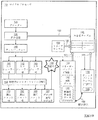
図1は、本発明の実施形態にしたがって作られたマイクロプロセッサ110の構成要素を示すブロック図である。
マイクロプロセッサ110は命令語を受信し、この命令語をマイクロオペレーション(以下、micro−ops)として知られるマイクロ命令語(micro−operation)にデコーディングするデコーダー120を含む。
FIG. 1 is a block diagram illustrating components of a microprocessor 110 made in accordance with an embodiment of the present invention.
The microprocessor 110 includes a
マイクロプロセッサ110は、また「micro−ops」を実行する1つ以上の実行ユニットを含む。
図1では、3つの実行ユニット、即ち、実行ユニット−A(151)、実行ユニット−B(152)、実行ユニット−C(153)が示される。但し、ユニットの名は例示として示したものであり、本発明の技術的思想はこれに限定されない。
The microprocessor 110 also includes one or more execution units that execute "micro-ops".
In FIG. 1, three execution units are shown: Execution Unit-A (151), Execution Unit-B (152), Execution Unit-C (153). However, the names of the units are shown as examples, and the technical idea of the present invention is not limited thereto.
デコーダー120と実行ユニット(151、152、153)とはパイプ(pipe)と呼ばれる部分の一部分であり、このパイプは付加的な構成要素を含む。
このような付加的な構成要素の中の1つは、結局のところ、「micro−ops」を実行ユニットに発送する(dispatching)ように提供されるディスパッチャー140である。
図1の例で、ディスパッチングは、3つのスケジューラー、即ち、スケジューラー−A(141)、スケジューラー−B(142)、及びスケジューラー−C(143)の中の1つの直前で実行される。
スケジューラーは、「micro−ops」を実行ユニット(151、152、153)に伝送する。この実行ユニットは物理的レジスターファイルPRF(Physical Register File)150からソースを読み出して、「micro−ops」を実行する。当業者は上述した内容がパイプの構造に対する一実施形態に過ぎなく、他の構造が可能であることを明確に理解できる。
The
One such additional component is, eventually, a
In the example of FIG. 1, dispatching is performed immediately before one of three schedulers: scheduler-A (141), scheduler-B (142), and scheduler-C (143).
The scheduler transmits "micro-ops" to the execution units (151, 152, 153). This execution unit reads the source from the physical register file PRF (Physical Register File) 150 and executes "micro-ops". Those skilled in the art can clearly understand that the contents described above are only one embodiment for the structure of the pipe, and that other structures are possible.
マイクロプロセッサ110は、再命名器(renamer)130を付加的に含み、この再命名器はデコーダー120から「micro−ops」を受信する。
再命名器130は、「micro−ops」にしたがって再命名データを生成する。
マイクロプロセッサ110は、さらに再命名テーブル136を含む。
再命名(rename)テーブル136は、再命名データを格納し、矢印(符号135)にしたがって再命名器130から受信する。
The microprocessor 110 additionally includes a
The
The microprocessor 110 further includes a rename table 136.
The rename table 136 stores rename data and receives from the
マイクロプロセッサ110は、リオーダーバッファ(Re−Order Buffer:以下、ROB)160を含む。
ROB160は、図1に個別的に開示していないROBエントリを含む。
以下で詳述するが、ROB160は、各々ROBエントリの中で可変的な1つのエントリをポインティングするリタイアポインター(Retire Pointer)とフラッシュポインター(Flush Ponter)を含む。
ROB160は循環されることもあり(circular)、循環されないこともあり得る。
The microprocessor 110 includes a re-order buffer (hereinafter, ROB) 160.
The
As described in detail below, the
ROBエントリは、「micro−ops」から生成されたROBデータ162を格納するためのものである。
一実施形態においては、各ROBエントリは、1つの「micro−ops」を格納するが、他の実施形態では、さらに多い「micro−ops」が1つのROBエントリに格納され得る。
ROBデータ162は、望ましくは、再命名テーブル136に格納された再命名データに応答する再構成再命名データ182を含む。
図1の実施形態でROBデータ162は、ディスパッチャー140から受信する。
The ROB entry is for storing
In one embodiment, each ROB entry stores one "micro-ops", but in other embodiments, more "micro-ops" may be stored in one ROB entry.
The
マイクロプロセッサ110は、チェックポイントテーブル(Check−Point table:以下、CPT)170をさらに含む。
CPTに対して可能である具現化は、以下でさらに詳細に敍述する。
CPT170は、再命名テーブル136とその広さが同一である。
CPT170は、図1に個別的には示さなかったがCPTエントリを有する。
CPTエントリの個数は、再命名テーブル136の個数と同一であり、これはCPTが再命名テーブル136のような深さ(depth)を有することを意味する。
CPTエントリの数はCPT深さを定義する。
The microprocessor 110 further includes a Check-Point table (hereinafter referred to as CPT) 170.
Possible implementations for CPT are described in more detail below.
The
The number of CPT entries is the same as the number of rename tables 136, which means that the CPT has a depth like the rename table 136.
The number of CPT entries defines the CPT depth.
CPTエントリは、再命名テーブル136に格納された再命名データのチェックポイントされたバーション180を格納する。
再命名データのチェックポイントされたバーション180は、再命名データを生成する任意のバーションであるか、或いは、再命名データそれ自体であり、このような場合、再命名データはCPT170に格納されるので、チェックポイントされた再命名データ(check−pointed rename data)180と称される。
図1の実施形態で、再命名データのチェックポイントされたバーション180は、ディスパッチャー140から受信する。
The CPT entry stores a
The
In the embodiment of FIG. 1, a
以下でより詳細に説明するように、ROBチェックポイントウインドウは、ROBチェックポイントウインドウがROBエントリに対して固定される静的関係(符号188)にしたがってCPTにマッピングされる。
静的関係(符号188)は、以下で詳述するように、固定される。
このような方式でROBエントリに新しい「micro−ops」が割り当てられれば、選択されたCPTエントリは、「micro−ops」が目的地を有する場合、「micro−ops」に対する目的地再命名情報(destination rename information)としてアップデートされる。
As described in more detail below, the ROB checkpoint window is mapped to CPT according to the static relationship (188) in which the ROB checkpoint window is fixed for ROB entries.
The static relationship (code 188) is fixed as detailed below.
If a new "micro-ops" is assigned to the ROB entry in this manner, the selected CPT entry will have destination renaming information ("micro-ops") if the "micro-ops" has a destination. Updated as destination rename information).
上述したように、再命名テーブル136はフラッシュ(flush)される。より正確には、これは再命名テーブルに格納された再命名データがフラッシュされたことを意味する。
図1の実施形態で、マイクロプロセッサ110は、ブランチ実行ロジック157を含む。
ブランチ実行ロジック157は、フラッグ(符号190)で示される「micro−ops」の実行の中の予測ミス(符号190)を感知することができる。
再命名テーブル136は、予測ミス(符号190)の感知に応答してフラッシュされる。
As mentioned above, the rename table 136 is flushed. More precisely, this means that the renaming data stored in the renaming table has been flushed.
In the embodiment of FIG. 1, microprocessor 110 includes
The
The rename table 136 is flushed in response to sensing a misprediction (code 190).
再命名テーブル136がフラッシュされれば、以後、再構成することができる。
再構成の目的のために、マイクロプロセッサ110は、リタイアチェックポイントデータ(retire check−point data)を格納するリタイアテーブル138を包含することができる。
リタイアチェックポイントデータは、再構成の開始過程で矢印(符号139)にしたがって再命名テーブル136にコピーされ得る。
再構成の目的のために、フラッシュされた再命名データは、リタイアテーブルからの初期コピーを追加的に、データの2つのデータソース(data of sources)から再命名テーブル136に再格納することができる。
Once the rename table 136 is flushed, it can be reconfigured thereafter.
For purposes of reconfiguration, microprocessor 110 may include a retire table 138 that stores retire check-point data.
Retire checkpoint data may be copied to the rename table 136 according to the arrow (reference numeral 139) at the start of reconstruction.
For purposes of reconstruction, the flushed renaming data can be restored to the renaming table 136 from two data of sources in addition to the initial copy from the retirement table .
最初に、再命名データのチェックポイントされたバーション180は、矢印(符号175)にしたがって多量流入(mass importation)の形態にてCPT170から再命名テーブル136にコピーされ得る。
多量流入は、以下で説明するように、静的関係(符号188)の観点から許諾される場合、同時に生じるコピーで具現され得る。
第2に、ROBデータ162内の再構成再命名データ182の少なくとも一部分は、矢印(符号160)にしたがってROB160から再命名テーブル136にコピーされ、これは“walking the ROB”としても公知されたプロセスである。
Initially, a
The mass inflow may be embodied in simultaneously occurring copies if permitted from the perspective of the static relationship (code 188), as described below.
Second, at least a portion of the
上述したように、CPT170に対する多数の可能である具現化があり得る。
このような具現化は、プロセッサ時間を倹約するために、矢印(符号165)のコピーが成される間に、矢印(符号175)の同時コピーを経て再構成の目的のために具現することができることを分かる。実施形態は以下で記述する。
As mentioned above, there may be many possible implementations for
Such an implementation may be implemented for the purpose of reconstruction via simultaneous copying of the arrow (175) while copying of the arrow (165) is made, in order to conserve processor time. I know what I can do. Embodiments are described below.
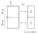
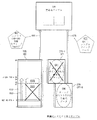
図2A、図2Bは、ROBの一部分のみがCPTにマッピングされる実施形態を説明するための図である。
より具体的には、ROB260は、ROB“0”から“95”に命名された96個のエントリを有する。
ROB260は、ROBエントリの中で任意の数を有することができる。そして、1つのCPTが提供される。
FIGS. 2A and 2B are diagrams for describing an embodiment in which only a part of ROB is mapped to CPT.
More specifically,
The
さらに、ROBチェックポイントウインドウは、ROB260に定義されることができ、エントリの任意の数からなされたグループであり得る。
この場合、ROBチェックポイントウインドウは、ROBエントリ“0”から“47”になされたグループである。
何らかのグループであることとは関係なく、ROBチェックポイントウインドウは、96個のROBチェックポイントウインドウに対して固定される。
このように、静的関係(符号288−1)は、ROB、より具体的にはROBチェックポイントウインドウが、CPT270にマッピングされる方法を示す。
このマッピングは、しばしば連関(association)であると称される。
本実施形態で、ROB260の中でROBエントリ“48”から“95”まではCPT270にマッピングされない。
Further, the ROB checkpoint window may be defined in
In this case, the ROB checkpoint window is a group formed from ROB entries "0" to "47".
The ROB checkpoint window is fixed relative to the 96 ROB checkpoint windows, regardless of being a group.
Thus, the static relationship (symbol 288-1) indicates how ROBs, and more specifically, ROB checkpoint windows are mapped to
This mapping is often referred to as association.
In the present embodiment, ROB entries “48” to “95” in the
再構成の目的のために、特定構成要素はそれ自体が格納されたROBエントリ又は連関されたCPTから再構成テーブルに再格納することができる。
仮にCPTからのコピーが許容されれば、この過程はより早くなり得る。
適用可能である静的関係(この実施形態で、符号288−1)は、ROB260からのみでなく、CPT270からも再構成をしなければならないか否か、及びどの程度に再構成しなければならないかに対して部分的に関与する。
実際には、静的関係(符号288−1)の観点から許諾されることによって、CPT270からのコピーが行われる。
許諾される場合に対する実施形態を以後に開示する。
For the purpose of reconstruction, a particular component can be restored to the reconstruction table from the ROB entry itself or the associated CPT.
This process can be faster if copying from CPT is allowed.
The applicable static relationship (in this embodiment, 288-1 in this embodiment) should and should be reconfigured not only from
In practice, copying from the
An embodiment for the permitted case will be disclosed hereinafter.
図2Aの実施形態が好ましいものではないかどうかに関係なく、すべてのROBエントリがCPTにマッピングされるROBチェックポイントウインドウの部分ではない。
したがって、ROB260がウォーキング(walking)されなければならないさらに多いシナリオが存在し、このようなシナリオは以下でより詳細に説明される。
Regardless of whether the embodiment of FIG. 2A is not preferred, not all ROB entries are part of the ROB checkpoint window that is mapped to CPT.
Thus, there are many more scenarios in which the
一実施形態において、付加的なCPT、即ち図1に示したCPT170、又は図2Aに示したCPT270に、付加的なCPTが提供される。
図2Aとは異なり、すべてのROBエントリが、上述されたCPT又は付加的なCPTにマッピングされる。
図2B、図2Cを参照して、2つの実施形態を開示する。
In one embodiment, additional CPTs are provided, namely,
Unlike in FIG. 2A, all ROB entries are mapped to the CPT or additional CPTs described above.
Two embodiments are disclosed with reference to FIGS. 2B and 2C.
図2Bは、ROB260と同様に96個のROBエントリを有するROB261を示す。
ROB261は、2つの静的ROBチェックポイントウインドウ、即ち“0”から“47”のROBエントリを含むウインドウ、ROBエントリ“48”から“95”を含むウインドウに分けられる。
また、2つのCPT、即ち、CPT−0(271)及びCPT−1(272)が存在する。
CPT(271、272)は、再命名テーブルの深さと同一の深さを有する。
図2Bの実施形態で、ROBチェックポイントウインドウ−0とCPT271との間の連関と、ROBチェックポイントウインドウ−1とCPT272との間の連関に、図に示す静的関係(符号288−2)が存在する。
FIG. 2B shows an
The
Also, there are two CPTs, CPT-0 (271) and CPT-1 (272).
The CPT (271, 272) has the same depth as the rename table depth.
In the embodiment of FIG. 2B, the static relationship (symbol 288-2) shown in the figure is the relationship between
図2Cは、96つのエントリを有するROB263を開示する。
また、各々ROB263のROBチェックポイントウインドウに対応する4つのCPT、即ちCPT−0(273)、CPT−1(274)、CPT−2(275)、及びCPT−3(276)が存在する。
発明を実施するために要求されるものではないが、4つのROBチェックポイントウインドウの各々は同一の深さを有する。
静的関係(符号288−3)は、静的関係(符号288−2)と同様に、固定された一対一の連関関係のグループに対するものである。
以下と合わせて、大部分の場合、図2Cの実施形態は、4つのCPTを有するので、単なる2つを有する時とは異なり、再命名テーブルを再構成するのに要求されるサイクルの数が減少することを分かる。
FIG. 2C discloses an ROB 263 having 96 entries.
Also, there are four CPTs, CPT-0 (273), CPT-1 (274), CPT-2 (275), and CPT-3 (276), each corresponding to the ROB checkpoint window of ROB 263.
Although not required to practice the invention, each of the four ROB checkpoint windows has the same depth.
The static relationship (symbol 288-3) is similar to the static relationship (symbol 288-2), and is for a fixed group of one-to-one relationships.
Together with the following, in most cases the embodiment of FIG. 2C has four CPTs, so unlike the case with just two, the number of cycles required to reconstruct the rename table is We know that it decreases.
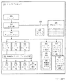
図3A、図3B、図3Cは、本発明の本実施形態によって作られたサンプルマイクロプロセッサに対するサンプルシークェンスを説明するためのブロック図である。
マイクロプロセッサ310は、デコーダー320、再命名器330、再命名テーブル336、リタイアテーブル338、ディスパッチャー340、スケジューラー(341、342、343)、物理的レジスターファイル(PRF)350、実行ユニット(351、352、353)、ブランチ実行ロジック357、及びROB360を含み、これは図1と同様の構成要素を参照して説明される。
FIGS. 3A, 3B and 3C are block diagrams illustrating sample sequences for a sample microprocessor made in accordance with this embodiment of the invention.
The microprocessor 310 includes a
ROB360は、ROBデータ162と同様のROBデータ362を格納する。
ROBデータ362は、再構成再命名データ182と同様の再構成再命名データ382を含む。
また、マイクロプロセッサ310は、ROB360と静的関係を有する2つのCPT、即ち、CPT−0(370)及びCPT−1(371)を含む。
CPT−0(370)及びCPT−1(371)は、図2Bの静的関係(符号288−2)と同様の静的関係を有する。
CPT−0(370)及びCPT−1(371)は静的関係にしたがって各々チェックポイントされた再命名データ380、381を格納する。
The
The
Also, microprocessor 310 includes two CPTs that have a static relationship with ROB 360: CPT-0 (370) and CPT-1 (371).
CPT-0 (370) and CPT-1 (371) have the same static relationship as the static relationship (symbol 288-2) of FIG. 2B.
CPT-0 (370) and CPT-1 (371) store the
図3Aで、マイクロプロセッサ310は、ノーマル動作を実行する。
命令語はパイプを通じてデコーダー320から受信され、実行ユニット(351、352、353)で実行される。
図3Bで、フラッグとして示す予測ミス(符号390)が感知される。
その結果、再命名テーブル336はフラッシュ(符号392)され、コメントによって示される。
図3Cで、コメント「再成」(符号393)によって示すように、再命名テーブル336は再構成される。
その結果、コメント「停止」(符号391)が示すようにパイプのフロントエンドで停止が発生する。
In FIG. 3A, microprocessor 310 performs a normal operation.
The instruction word is received from the
In FIG. 3B, a misprediction (code 390), shown as a flag, is sensed.
As a result, the rename table 336 is flushed (392) and indicated by the comment.
The rename table 336 is reconfigured, as shown by the comment "reconstruction" (symbol 393) in FIG. 3C.
As a result, a stop occurs at the front end of the pipe as indicated by the comment "stop" (reference numeral 391).
再構成は次のように実行される。
最初に、リタイアチェックポイントが矢印(符号339)にしたがってリタイアテーブル338からコピーされる。
再構成は、2つの他のソースから来るデータによって実行される。
チェックポイントされた再命名データ(380、381)は、適用可能である静的関係の観点から許諾された場合、矢印(符号375、376)にしたがってコピーされる。
そして、再命名データ382は矢印(符号365)にしたがってROB360をウォーキング(walking)することによってコピーされる。
Reconfiguration is performed as follows.
First, retire checkpoints are copied from the retire table 338 according to the arrows (339).
Reconfiguration is performed by data coming from two other sources.
Checkpointed rename data (380, 381) is copied according to the arrows (
Then, the
しかし、一部の特別な場合には以下のサンプルシナリオに開示するように、2つのソースの中で1つのソースは関与しないことがあり得る。
マイクロプロセッサ310は、一般的に、図に示さなかったクロックを含む。
クロックは、クロックサイクルを定義するパルスを出力する。
クロックサイクルは、本発明の長所を評価する良い方法である。実施形態を以下に説明する。
However, one source may not be involved in the two sources, as disclosed in the sample scenario below in some special cases.
The microprocessor 310 generally includes a clock not shown.
The clock outputs a pulse that defines a clock cycle.
Clock cycles are a good way to evaluate the advantages of the present invention. Embodiments are described below.
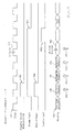
図4は、図3Cでのような再命名テーブルを再構成することに対する相対的なタイミングパルス図である。
クロックサイクル412は、シングルパルス(single pulse)で示すNサイクルのグループ415を含む。数字“N”は後で詳細に説明する。
図4では予測ミスを感知し、以後のペナルティー(penalties)を説明する。
FIG. 4 is a relative timing pulse diagram for reconstructing the rename table as in FIG. 3C.
FIG. 4 detects a misprediction and explains the subsequent penalty.
パルス492はコメント(符号392)による再命名テーブル336のフラッシング(flushing)に対応する。
延長された停止パルス491はコメント(符号391)による、パイプ(pipe)が停止された時間に対応する。
パルス491の持続は、予測ミスに対する時間ペナルティー及び以後のマイクロプロセッサの動作性能減少と関連する。
パルス491とサイクルのグループ415で、仮に“N”が大きければ、ペナルティーはさらに大きい。
パルス493Aとパルス493Bは、コメント(符号393)に対応して各々再構成の開始と終了を示す。
The
The
The duration of the
At
一般的に、再命名サイクル436は、サイクル439、サイクル475、サイクル476、N個のサイクルのグループ465を含む。
サイクル439は、矢印(符号339)の動作実行の際に、リタイアチェックポイントをコピーするためのものである。
サイクル475は、矢印(符号375)にしたがってCPTから同時にコピーするためのものである。
サイクル476は、矢印(符号376)にしたがって他の同時コピーに関するものである。
Generally, rename
A
The
N個のサイクルのグループ465は、矢印(符号365)にしたがってROBをウォーキング(walking)するためのものである。
サイクルのグループ415と同様に、サイクル465は1つで図に示している。
但し、これは例示的なものであり、サイクルのグループ415とサイクル465とはN値を有することもあり得る。
矢印(符号339、375、376、365)は理解の便宜を助けるために図4で適切な位置で反復される。
しかし、具体的に、再命名サイクル436の一部は、毎度は包含されない。
いずれかが含まれ、いずれかが含まれないかに関する問題は予測ミスが感知され、以後の再命名テーブルがフラッシュされる時点で定義されるシナリオによる。具体的な動作のシナリオは図4を参照して説明する。
A
As with group of
However, this is an example, and the group of
Arrows (339, 375, 376, 365) are repeated at appropriate locations in FIG. 4 to aid in ease of understanding.
However, specifically, part of the
The question of whether one is included and not included depends on the scenario being defined when a misprediction is detected and a subsequent rename table is flushed. A specific operational scenario is described with reference to FIG.
最初に、シナリオを理解するために、ROB再構成ウインドウは、再命名テーブルがフラッシュされる時、定義されたと認識されなければならない。
ROB再構成ウインドウは、リタイアポインターから開始し、フラッシュポインターが1つ先行するところで終了するROBエントリを有する。
ROB再構成ウインドウ内のROBエントリは、再命名テーブルに再格納される必要があると定義され、再格納は、1つ又はそれ以上のCPTからの同時のコピー動作又はROBをウォーキング(walking)する動作のいずれか1つによって実行される。
各場合において、ROBから再命名テーブルにコピーされる再構成再命名データの部分はROB再構成ウインドウ内に属する。
First, in order to understand the scenario, the ROB reconfiguration window should be recognized as defined when the rename table is flushed.
The ROB reconstruction window has an ROB entry starting from the retire pointer and ending one flash pointer ahead.
ROB entries in the ROB reconfiguration window are defined as needing to be stored back in the renaming table, which walks in parallel copying operations or ROBs from one or more CPTs. Performed by any one of the actions.
In each case, the portion of the reconfiguration rename data copied from the ROB to the rename table belongs within the ROB reconfiguration window.
シナリオは、再命名テーブルがフラッシュされる時毎に異なり、ROB再構成ウインドウは一般的に互に異なるROBエントリのセットを包含する。
異なるシナリオ自体は、ROB再構成ウインドウが以前に言及されたROBチェックポイントウインドウの深さと関連して、どのようにして異なる大きさを有するのかを検証する。
また以下のシナリオの一側面は、CPTテーブルが同時に再命名テーブルにコピーされることが許諾されるか否か、又はROBをワーキング(walking)することによって同一の内容がコピーされるか否かを判断することに連関する。
The scenario is different each time the renaming table is flushed, and the ROB reassembly window generally contains a different set of ROB entries.
The different scenarios themselves verify how the ROB reconstruction window has different sizes in relation to the depth of the ROB checkpoint window mentioned previously.
Also, one aspect of the following scenario is whether the CPT table is permitted to be copied to the rename table at the same time, or whether the same content is copied by walking the ROB. It relates to making a judgment.
このようなシナリオの多様な例を説明する。
シナリオの説明をするために、ROB360とCPT(370、371)とが図2Bで示したものと同様なものが使用されたと仮定する。
さらに、静的関係(符号288−2)と同様のROBチェックポイントウインドウとCPT(370、371)を示す波括弧によって示される静的関係が適用される。
Various examples of such scenarios are described.
To illustrate the scenario, assume that
Furthermore, the static relationship indicated by the ROB checkpoint window and the CPT (370, 371) similar to the static relationship (symbol 288-2) is applied.
図5は、本発明からの有利な結果がない第1サンプルシナリオに対する、図3Cの構成要素を示す図である。
CPT−0(370)はチェックポイントされた再命名データ580を格納し、CPT−1(371)はチェックポイントされた再命名データ581を格納する。
矢印で示したROB再構成ウインドウ563は、リタイアポインターが示すROBエントリ“15”で始めて、フラッシュポインターが示すROBエントリ“38”より1つ小さいROBエントリ“37”で終了する。
ROB再構成ウインドウ563内のROBデータ562は、CPT(370、371)からの同時コピー又は直接的にROB360をウォーキングすることによって再命名テーブル336に再格納される再構成再命名データ582を含む。
FIG. 5 is a diagram showing the components of FIG. 3C for a first sample scenario without advantageous results from the present invention.
CPT-0 (370) stores checkpointed rename
The
The
本実施形態で、ROB再構成ウインドウ563は全て、ROBエントリ“0”から“47”になされたROBチェックポイントウインドウ内にある。
このように、チェックポイントされた再命名データ581は、図で線を引いて消されたように、要求されない。
さらに、ROBエントリ“38”で“47”までのコンテンツはフラッシュされ、したがってチェックポイントされた再命名データ580は、CPT−0(370)が全て再命名テーブル336にコピーされるので、再構成プロセスの一部として再命名テーブルにコピーされない。
このように、チェックポイントされた再命名データ580もやはり、図で線を引いて消されたように要求されない。
したがって、コメント(符号567)によって、すべてのROBエントリ“15”〜“37”内の再構成再命名データ582は矢印(符号565)にしたがって、即ち、ROB360をウォーキングすることによって再格納される。
In this embodiment, the
Thus,
In addition, the ROB entry "38" up to "47" is flushed, so the
Thus,
Therefore, according to the comment (symbol 567), the
したがって、コメント(符号567)に対して、ROBエントリ“15”〜“37”内の再構成再命名データ582は矢印(符号565)にしたがって、例えばROB360をウォーキングすることによって、再格納される。
言い換えれば、図5のCPTは、再構成のために使用されなく、したがって、本発明は図5のシナリオでは長所を提供しない。
図5のシナリオに対して図4を簡略的に参照すれば、再命名サイクル475と再命名サイクル476とは全て包含しなく、数字“N”は最大“m”であり、ここで、“m”はこのようなシナリオの下でROB360がウォーキングされることができる最も多い段階の数を示す。
停止パルス491の期間は本発明ではない状態では減少しない。このようなことは残るシナリオ例では適用されない。
Therefore, with respect to the comment (symbol 567), the
In other words, the CPT of FIG. 5 is not used for reconstruction, so the present invention does not provide the advantages in the scenario of FIG.
Referring briefly to FIG. 4 for the scenario of FIG. 5, the renaming
The duration of the
図6は、第2サンプルシナリオのための図3Cの構成要素を示す図である。
CPT−0(370)はチェックポイントされた再命名データ部分680を格納し、CPT−1(371)はチェックポイントされた再命名データ部分681を格納する。
ROB360内のROB再構成ウインドウ663は“15”から“54”のROBエントリに掛かっている。
ROB再構成ウインドウ663内で、ROBデータ662は、再命名テーブル336に再格納される再構成再命名データの一部分(682A、682B)を含む。
再構成再命名データをROB360内の所定部分(682A、682B)に分割したことがROBチェックポイントの境界で発生したことにより理解できる。
実際に、“15”から“47”のROBエントリはチェックポイントされた再命名データ部分680にマッピングされ、“48”から“54”のROBエントリはチェックポイントされた再命名データ部分681にマッピングされる。
FIG. 6 is a diagram showing the components of FIG. 3C for a second sample scenario.
CPT-0 (370) stores the checkpointed
The
Within the
It can be understood that the division of the reconstruction rename data into predetermined parts (682A, 682B) in the
In fact, ROB entries "15" to "47" are mapped to the checkpointed
チェックポイントされた再命名データ部分680は使用可能であり、コメント(符号677)によって、矢印(符号675)にしたがって再格納される。
したがって、再構成再命名データ部分682Aは必要としないようになって、示したように図で線を引いたように消される。
しかし、チェックポイントされた再命名データ部分681は、図5でと同様の理由で使用されないので、図に線を引いて示したように消される。
コメント(符号667)によって、“48”から“54”のROBエントリ内の再構成再命名データ部分682BはROB360をウォーキング(walking)することによって矢印(符号665)にしたがって再格納される。
The checkpointed
Thus, the reconfiguration
However, since the checkpointed
The comment (code 667) causes the reconfiguration
図4を参照すれば、矢印(符号675)にしたがって再格納することは、1つのクロックパルス475内で発生し、クロックパルス476内では存在しない。
“N”は“m”より小さく、“0”より大きく、停止パルス491の持続期間は本発明によって減少される。
図6のシナリオでの再構成は、図5に比べてさらに多いデータをコピーことを要求するように見えるが、本発明の技術的思想によれば、より短い時間の所要ですむ。
Referring to FIG. 4, restoration according to arrow (675) occurs within one
"N" is less than "m" and greater than "0", and the duration of the
The reconstruction in the scenario of FIG. 6 appears to require copying more data than in FIG. 5, but according to the technical idea of the present invention it takes less time.
図7は、第3サンプルシナリオのための図3Cの構成要素を示す図である。
CPT−0(370)はチェックポイントされた再命名データ部分780を格納し、CPT−1(371)はチェックポイントされた再命名データ部分781を格納する。
ROB再構成ウインドウ763は“80”のROBエントリから始めて、“95”のROBエントリから“0”のROBエントリを経て、“9”のROBエントリまで続ける。
FIG. 7 is a diagram showing the components of FIG. 3C for a third sample scenario.
CPT-0 (370) stores the checkpointed
The
これは、ROB360がROBデータを循環キュー(circular queue)内に格納することを、囲むような矢印(符号768)によって示している。
ROBデータ部分762Aは再構成再命名データ部分782Aを含み、ROBデータ部分762Bは再構成再命名データ部分782Bを含む。
“80”から“95”のROBエントリはチェックポイントされた再命名データ部分781にマッピングされ、“0”から“9”のROBエントリはチェックポイントされた再命名データ部分780にマッピングされる。
This is illustrated by the circling arrows (symbol 768) that the
The
ROB entries "80" to "95" are mapped to the checkpointed
チェックポイントされた再命名データ部分781は使用可能であり、コメント(符号777)によって、矢印(符号776)にしたがって再格納される。
したがって、再構成再命名データ部分782Aは必要がなくなって、図に線を引いて示したように消される。
しかし、チェックポイントされた再命名データ部分780は、図5でと同様の理由で使用できなくなり、コメント(符号767)によって、再構成再命名データ782Bが矢印(符号765)にしたがってROB360をウォーキング(walking)して再格納される。
The checkpointed
Thus, the reconfiguration
However, the checkpointed
図4を参照すれば、矢印(符号776)にしたがって再格納することは1つのクロックパルス476内で発生し、クロックパルス475内では存在しない。
“N”は“0”より大きく、“m”より小さく、停止パルス491の持続期間は本発明によって最少化される。
Referring to FIG. 4, restoration according to arrow (776) occurs within one
"N" is greater than "0" and less than "m", and the duration of the
図8は、第4サンプルシナリオに対する図3Cの構成要素を示す図である。
CPT−0(370)はチェックポイントされた再命名データ部分880を格納し、CPT−1(371)はチェックポイントされた再命名データ部分881を格納する。
ROB再構成ウインドウ863はROBエントリ“80”で始めて、ROBエントリ“95”でROBエントリ“0”を含んで、ROBエントリ“74”まで続けることを図に示す。
FIG. 8 shows the components of FIG. 3C for the fourth sample scenario.
CPT-0 (370) stores the checkpointed
The
ROBデータ部分862Aは再構成再命名データ部分882Aを含み、ROBデータ部分862Bは再構成再命名データ部分882Bを含み、ROBデータ部分862Cは再構成再命名データ部分882Cを含む。
ROBエントリ“80”〜“95”及び“48”〜“74”はチェックポイントされた再命名データ部分881にマッピングされ、ROBエントリ“0”〜“47”はチェックポイントされた再命名データ部分880にマッピングされる。
The
ROB entries "80" to "95" and "48" to "74" are mapped to checkpointed
チェックポイントされた再命名データ部分880は使用可能であり、コメント(符号877)に対して、矢印(符号875)にしたがって再格納される。
したがって、再構成再命名データ部分(882B)は、図で線を引いて消されたように必要としない。
しかし、チェックポイントされた再命名データ部分881は使用可能でない。
したがって、コメント(符号867)によって、再構成再命名データ部分882A及び882Cは矢印(符号865)にしたがって、即ちROB360をウォーキングすることによって再格納される。
The checkpointed
Thus, the reconfiguration rename data portion (882B) does not need to be delineated in the figure.
However, the checkpointed
Thus, according to the comment (code 867), the reconfiguration
図4を参照すれば、クロックパルス476が存在しない間に、1つのクロックパルス475で矢印(符号875)にしたがって、再格納が実行される。
“N”は“0”よりは大きく、“m”よりは小さく、本発明によって停止パルス491は減少される。
Referring to FIG. 4, while the
"N" is greater than "0" and less than "m", and the
図9は、第5シナリオに対する図3Cの構成要素を示す図である。
CPT−0(370)はチェックポイントされた再命名データ部分980を格納し、CPT−1(371)はチェックポイントされた再命名データ部分981を格納する。
ROB再構成ウインドウ963はROBエントリ“0”〜“48”に掛かっている。
ROBデータ962は再構成再命名データ982を含む。
言い換えれば、ROBエントリ“0”〜“47”はROBチェックポイントウインドウの下の部分に正確に包含される。これは特別な場合であり、統計的に小さい頻度で発生する。
FIG. 9 shows the components of FIG. 3C for the fifth scenario.
CPT-0 (370) stores the checkpointed
The
In other words, ROB entries "0" to "47" are correctly included in the lower part of the ROB checkpoint window. This is a special case and occurs statistically less frequently.
チェックポイントされた再命名データ部分980は使用可能であり、コメント(符号977)によって、矢印(符号975)にしたがって再格納される。
したがって、再構成再命名データ部分982は図で線を引いて消されたように必要としない。
さらに、このシナリオでコメント(符号967)によってROB360のウォーキングは無く、何らかの再構成再命名データもROB360から再命名テーブル336にコピーされない。従って、チェックポイントされた再命名データ部分981もやはり線を引いて消されたように必要としない。
The checkpointed
Thus, the reconfiguration
Furthermore, in this scenario there is no
図4を参照すれば、クロックパルス476が存在しない間に、1つのクロックパルス475で矢印(符号975)にしたがって、再格納が実行される。
“N”は“0”になり、パルス415、465のグループはない。本発明によって停止パルス491は減少される。
Referring to FIG. 4, while
"N" becomes "0" and there is no group of
図10は、本発明の実施形態による半導体装置と共に動作するシステムを含む電子機器を示すブロック図である。
システム1000は、PDA(personal digital assistant)、ラップトップコンピュータ、モバイルコンピュータ、ウェブタブレット、無線フォン、携帯電話機、デジタル音楽再生器、有線又は無線電気装置、又は少なくとも前記の機器の中で2つ以上を含む複合電子装置内で使用され得る。
FIG. 10 is a block diagram illustrating an electronic device that includes a system that operates with a semiconductor device according to an embodiment of the present invention.
The
システム1000は、コントローラ1010、キーパッド(keypad)、キーボード(keyboard)、ディスプレイのような入出力装置1020、メモリ1030、バス1050を通じて互に通信するインターフェイス1040を包含する。
コントローラ1010は、例えば、本発明の実施形態にしたがって製造された少なくとも1つのマイクロプロセッサ、デジタル信号プロセッサ、マイクロコントローラのようなものを包含する。
The
メモリ1030は、コントローラ810によって使用される命令語及び/又は入出力装置を経てアクセス可能であるユーザーデータを格納する。
システム(或いは電子機器)1000は、通信ネットワークを通じてデータを伝送するか、或いは受信するユーザーインターフェイス1040を使用する。
伝送動作は、例えば、ケーブル、USBインターフェイスのような有線を経由することがあり得る。他の例として、通信ネットワークは無線であり、インターフェイス1040は無線であり、例えば、アンテナ、無線送受信機のようなものであり得る。
System (or electronics) 1000 uses a
The transmission operation may be via, for example, a wired connection such as a cable or USB interface. As another example, the communication network may be wireless, and the
システム(或いは電子機器)1000は、CDMA、GSM(登録商標)、NADC、E−TDMA、WCDMA(登録商標)、CDMA2000、Wi−Fi、Muni Wi−Fi、Bluetooth(登録商標)、DECT(登録商標)、Wireless USB、Flash−OFDM、IEEE 802.20、GPRS、iBurst(登録商標)、WiBro、WiMAX(登録商標)、WiMAX(登録商標)−Advanced、UMTS−TDD、HSPA、EVDO、LTEAdvanced、MMDSのような通信システムの通信インターフェイスプロトコル内で使用され得る。 The system (or electronic device) 1000 may be CDMA, GSM (registered trademark), NADC, E-TDMA, WCDMA (registered trademark), CDMA2000, Wi-Fi, Muni Wi-Fi, Bluetooth (registered trademark), DECT (registered trademark) ), Wireless USB, Flash-OFDM, IEEE 802.20, GPRS, iBurst (registered trademark), WiBro, WiMAX (registered trademark), WiMAX (registered trademark)-Advanced, UMTS-TDD, HSPA, EVDO, LTE Advanced, MMDS, Such may be used within the communication interface protocol of a communication system.
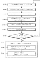
図11は、本発明の実施形態によるマイクロプロセッサの動作方法を説明するためのフローチャートである。
フローチャート1100の動作方法は、上述した実施形態、マイクロプロセッサ、電子装置によって実行される。
FIG. 11 is a flow chart for explaining the operation method of the microprocessor according to the embodiment of the present invention.
The method of operation of flowchart 1100 may be performed by the embodiments, microprocessors, and electronic devices described above.
まず、S1110段階にて、命令語を「micro−ops」にデコーディングする。
次に、S1120段階にて、再命名データが「micro−ops」によって発生する。
次に、S1130段階にて、再命名データを再命名テーブルに格納する。
First, in step S1110, the instruction word is decoded into "micro-ops".
Next, in step S1120, rename data is generated by "micro-ops".
Next, in step S1130, the rename data is stored in the rename table.
次に、S1140段階にて、再命名データのチェックポイントされたバーションをCPTに格納する。
次に、S1150段階にて、「micro−ops」から発生されたROBデータをROBに格納する。
ROBデータは必要である場合、結局のところ再命名テーブルを再構成するために使用される再構成再命名データを包含することができる。ROBはCPTと静的関係を維持する。
次に、S1160段階にて、「micro−ops」が実行される。
Next, in step S1140, the checkpointed version of the renaming data is stored in the CPT.
Next, in step S1150, ROB data generated from "micro-ops" is stored in ROB.
The ROB data can eventually include the reconfiguration rename data used to reconstruct the rename table, if needed. ROB maintains a static relationship with CPT.
Next, "micro-ops" is executed in step S1160.
次に、S1170段階にて、再命名テーブルがフラッシュされたか否かを判断する。
言い換えれば、再命名データは再命名テーブルからフラッシュされる。
仮に「いいえ」であれば、S1110段階にもどる。
一実施形態において、再命名テーブルは上述したように予測ミスを感知することに応答してフラッシュされる。
仮に再命名テーブルがフラッシュされたら(「はい」であれば)、以後のS1180段階にしたがって、再命名データを再命名テーブルに再格納する。即ち、再命名テーブルが再構成される。
Next, in step S1170, it is determined whether the rename table has been flushed.
In other words, rename data is flushed from the rename table.
If "no", the process returns to step S1110.
In one embodiment, the rename table is flushed in response to sensing a misprediction as described above.
If the rename table is flushed (if yes), the rename data is restored to the rename table according to the subsequent step S1180. That is, the rename table is reconfigured.
S1180段階は、S1182段階及びS1184段階の中で少なくとも1つを含む。
S1180段階で、ROBエントリのROB再構成ウインドウは再命名テーブルがフラッシュされた時、定義される。
ROB再構成ウインドウ内のこのようなROBエントリの再構成再命名データは、S1182段階によって、又はS1184段階によって再命名テーブルに再格納される。
Operation S1180 includes at least one of operation S1182 and operation S1184.
At step S1180, the ROB reconfiguration window of the ROB entry is defined when the rename table is flushed.
The reconfiguration rename data of such ROB entry in the ROB reconfiguration window is restored to the rename table by step S1182 or by step S1184.
S1182段階にて、再命名データのチェックポイントされたバーションは、仮にS1150段階の静的関係によって許諾されれば、CPTから再命名テーブルにコピーする。
一実施形態において、再命名データのチェックポイントされたバーションは1つのクロックサイクル内でコピーされる。
At S1182, the checkpointed version of the renaming data is copied from the CPT to the Renaming Table, if permitted by the static relationship of S1150.
In one embodiment, the checkpointed version of the rename data is copied in one clock cycle.
S1184段階にて、再構成再命名データはROBから再命名テーブルにコピーする。
望ましくは、これはS1182段階によってカバーされないで残ることに対して実行され、ROBをウォーキング(walking)することによって実行される。
At step S1184, reconfiguration rename data is copied from the ROB to the rename table.
Desirably, this is performed for remaining uncovered by step S1182 and is performed by walking the ROB.
なお、上述した動作の順序は例示的なものであり、本発明の技術的思想はこれに限定されない。例えば、上述した動作方法の順序は固定されたものでなく、本発明の技術的思想の他の実施形態にしたがって異なる順序によって実行することもできる。
さらに、他の実施形態で、新しい段階が追加されたり、各段階が修正されるか、或いは削除されることもあり得る。
In addition, the order of the operation | movement mentioned above is an illustration, The technical thought of this invention is not limited to this. For example, the order of operation methods described above is not fixed, and may be performed in a different order according to other embodiments of the inventive concept.
Furthermore, in other embodiments, new stages may be added, or each stage may be modified or deleted.
尚、本発明は、上述の実施形態に限られるものではない。本発明の技術的範囲から逸脱しない範囲内で多様に変更実施することが可能である。 The present invention is not limited to the above-described embodiment. Various modifications can be made without departing from the technical scope of the present invention.
110、310 マイクロプロセッサ
120、320 デコーダー
130、330 再命名器(renamer)
136、336 再命名テーブル
138、338 リタイアテーブル
140、340 ディスパッチャー
141〜143、341〜343 スケジューラー(A〜C)
150、350 物理的レジスターファイル(PRF)
151〜153、351〜353 実行ユニット(A〜C)
157、357 ブランチ実行ロジック
160、360 リオーダーバッファ(ROB)
162、362 ROBデータ
170、370、371 チェックポイントテーブル(CPT)
180 再命名データのチェックポイントされたバーション
182、382 再構成再命名データ
380、381 チェックポイントされた再命名データ
110, 310
136, 336 Renaming Table 138, 338 Retirement Table 140, 340
150, 350 Physical Register File (PRF)
151 to 153, 351 to 353 execution units (A to C)
157, 357
162, 362
180 Checkpointed version of renaming
Claims (16)
ディスパッチャー(dispatcher)と、
前記ディスパッチャーから受信した再命名データを格納するチェックポイントテーブル(Check Point Table:CPT)と、
リオーダーバッファ(Re−Order Buffer:ROB)エントリを含むリオーダーバッファとを有し、
前記再命名テーブルがフラッシュ(flush)されれば、前記再命名テーブルは、前記チェックポイントテーブルに格納された前記再命名データを利用して再構成(rebuild)され、
前記リオーダーバッファエントリのグループは、リオーダーバッファチェックポイントウインドウとして定義され、
前記リオーダーバッファチェックポイントウインドウと、前記チェックポイントテーブルとの間のマッピングは、固定された静的関係(static relationship)に従うものであり、
前記再命名テーブルは、静的関係の側面で許諾される場合のみ、前記チェックポイントテーブルに格納された前記再命名データを利用して再構成されることを特徴とするマイクロプロセッサ。 A renaming table for storing renaming data (rename data);
Dispatcher (dispatcher),
A Check Point Table (CPT) for storing renaming data received from the dispatcher;
And a reorder buffer (Re-Order Buffer: ROB) entry.
If the renaming table is flushed, the renaming table is rebuilt using the renaming data stored in the checkpoint table,
The group of reorder buffer entries is defined as a reorder buffer checkpoint window,
The mapping between the reorder buffer checkpoint window and the checkpoint table follows a fixed static relationship:
A microprocessor characterized in that the rename table is reconstructed using the rename data stored in the checkpoint table only when licensed in the aspect of static relationship .
前記予測ミスが感知されたことに応答して、前記再命名テーブルはフラッシュされることを特徴とする請求項1に記載のマイクロプロセッサ。 It further comprises branch execution logic to sense mis-prediction,
The microprocessor of claim 1, wherein the rename table is flushed in response to the misprediction being sensed.
前記再命名テーブルは、前記再命名器から前記再命名データを受信することを特徴とする請求項1に記載のマイクロプロセッサ。 It further has a renamer that generates rename data,
The microprocessor according to claim 1, wherein the rename table receives the rename data from the renamer.
前記再命名テーブルの再構成において、1つの前記チェックポイントテーブルから前記再命名テーブルへの再命名データのコピーは、前記クロックサイクルの中の1つのサイクル内で行われるものであることを特徴とする請求項1に記載のマイクロプロセッサ。 It further comprises a clock which outputs a pulse defining a clock cycle,
In the reconfiguration of the rename table, copying of rename data from one checkpoint point table to the rename table is performed in one cycle of the clock cycle. The microprocessor according to claim 1.
前記マイクロオペレーションを実行する実行ユニットと、
前記マイクロオペレーションにしたがって再命名データを生成する再命名器と、
再命名テーブルと、
前記再命名データのチェックポイントされたバーション(check−pointed version)を格納するチェックポイントテーブル(CPT)と、
前記マイクロオペレーションから生成されたリオーダーバッファ(Re−order Buffer:ROB)データを格納するリオーダーバッファエントリを有するリオーダーバッファとを有し、
前記再命名テーブルは、前記再命名データを格納するものであり、かつ、所定の条件が成立した場合には、前記再命名データが前記再命名テーブルからフラッシュされるものであり、
前記リオーダーバッファデータは、再構成再命名データを含み、
前記リオーダーバッファエントリのグループは、リオーダーバッファチェックポイントウインドウとして定義され、
前記リオーダーバッファチェックポイントウインドウと、前記チェックポイントテーブルの間のマッピングは、固定された静的関係に従うものであり、
前記静的関係の側面で許諾される場合のみ前記再命名データの前記チェックポイントされたバーションが前記チェックポイントテーブルから前記再命名テーブルにコピーされ、さらに、前記再命名テーブルにコピーされるべき再命名データのうち、残余のものが存在する場合には、前記再構成再命名データの少なくとも一部分が前記リオーダーバッファから前記再命名テーブルにコピーされることによって、
前記再命名テーブルに格納された再命名データが前記再命名テーブルからフラッシュされた場合、再命名データを前記再命名テーブルに再格納することができることを特徴とするマイクロプロセッサ。 A decoder for decoding instruction words into micro-ops;
An execution unit that executes the micro-operations;
A renamer that generates rename data according to the micro-operations;
Renaming table,
A checkpoint table (CPT) for storing a checked-pointed version of the renamed data;
And a reorder buffer having a reorder buffer entry for storing re-order buffer (ROB) data generated from the micro operation.
The renaming table stores the renaming data , and the renaming data is flushed from the renaming table when a predetermined condition is satisfied.
The reorder buffer data includes reconfiguration rename data,
The group of reorder buffer entries is defined as a reorder buffer checkpoint window,
The mapping between the reorder buffer checkpoint window and the checkpoint table follows a fixed static relationship,
The checkpointed version of the renaming data is copied from the checkpoint table to the renaming table only if permitted in the static relationship aspect, and further renaming should be copied to the renaming table At least a portion of the reconfiguration rename data is copied from the reorder buffer to the rename table, if the remaining one of the naming data is present,
A microprocessor characterized in that, when the rename data stored in the rename table is flushed from the rename table, the rename data can be restored to the rename table.
前記リオーダーバッファエントリは、前記チェックポイントテーブル又は前記付加的なチェックポイントテーブルにマッピングされることを特徴とする請求項5に記載のマイクロプロセッサ。 It additionally has an additional checkpoint table,
The microprocessor according to claim 5 , wherein the reorder buffer entry is mapped to the checkpoint table or the additional checkpoint table.
前記リオーダーバッファから前記再命名テーブルにコピーされる前記再構成再命名データの部分は、前記リオーダーバッファ再構成ウインドウ内に存在することを特徴とする請求項5に記載のマイクロプロセッサ。 If renaming data is flushed from the renaming table, a reorder buffer reassembly window of reorder buffer entries is defined,
6. The microprocessor according to claim 5 , wherein a portion of the reconfiguration rename data copied from the reorder buffer to the rename table is present in the reorder buffer reconfiguration window.
前記再命名データを格納する再命名テーブルと、
前記マイクロオペレーションから生成され再構成再命名データを格納するリオーダーバッファデータを格納するリオーダーバッファ(Re−Order Buffer:ROB)と、
前記再命名データのチェックポイントされたバーションを格納する2つ以上のチェックポイントテーブル(Check Point Table:CPT)とを有し、
前記リオーダーバッファと前記2つ以上のチェックポイントテーブルとの間には、静的関係(static relationship)を有し、前記2つ以上のチェックポイントテーブルは、前記静的関係にしたがって各々チェックポイントされた再命名データを格納し、
前記再命名テーブルに格納された再命名データが、前記再命名デーブルからフラッシュされる場合に、
必要であれば、前記リオーダーバッファから前記再命名テーブルにコピーされる再構成再命名データと、前記静的関係の観点から許容されるのであれば、前記2つ以上のチェックポイントテーブルの少なくともいずれかから前記再命名テーブルにコピーされる再命名データの前記チェックポイントされたバージョンの間に重複がないようにしつつ、前記コピーを行うことにより、再命名データを前記再命名テーブルに格納されることを特徴とするマイクロプロセッサ。 A renamer that generates rename data according to micro-ops,
A renaming table for storing the renaming data;
A re-order buffer (ROB) for storing re-order buffer data generated from the micro-operation and storing reconstruction renaming data;
Having two or more Check Point Tables (CPTs) storing checkpointed versions of the renaming data;
There is a static relationship between the reorder buffer and the two or more checkpoint tables, and the two or more checkpoint tables are each checkpointed according to the static relationship. Store the renamed data,
If the renaming data stored in the renaming table is flushed from the renaming table:
Reconfiguration Renaming data copied from the reorder buffer to the renaming table, if necessary, and at least one of the two or more checkpoint tables, if permitted from the viewpoint of the static relationship The renaming data is stored in the renaming table by performing the copying while ensuring that there is no duplication between the checkpointed versions of the renaming data copied from the corpora to the renaming table. A microprocessor characterized by
前記チェックポイントテーブルは、前記ディスパッチャーから前記再命名データの前記チェックポイントされたバーションを受信することを特徴とする請求項5又は8記載のマイクロプロセッサ。 Further comprising a dispatcher for dispatching said micro-operations to an execution unit ;
9. A microprocessor as claimed in claim 5 or 8 , wherein the checkpoint table receives the checkpointed version of the rename data from the dispatcher.
前記予測ミスが感知されたことに応答して、前記再命名データは、前記再命名テーブルからフラッシュされることを特徴とする請求項5又は8に記載のマイクロプロセッサ。 Further including branch execution logic for detecting mispredictions in the execution of said micro-operations;
9. The microprocessor according to claim 5 , wherein said rename data is flushed from said rename table in response to said misprediction being sensed.
前記再命名データの前記チェックポイントされたバーションが、前記クロックサイクル中の1つのサイクル内で前記チェックポイントテーブルから前記再命名テーブルにコピーされることを特徴とする請求項5又は8記載のマイクロプロセッサ。 Further including a clock that outputs a pulse defining a clock cycle,
9. A micro according to claim 5 or 8 , characterized in that said checkpointed version of said renaming data is copied from said checkpoint table to said renaming table within one cycle during said clock cycle. Processor.
前記バスに接続されたインターフェイスであって、通信ネットワークにデータを伝送し、前記通信ネットワークからデータを受信するように構成された前記インターフェイスと、
前記バスに接続された入出力装置と、
前記バスに接続され、前記入出力装置を通じてアクセス可能であるユーザーデータ又は命令語を格納するよう構成されたメモリと、
前記バスに接続され、前記命令語を利用するよう構成されたコントローラとを有し、
前記コントローラは、少なくとも1つのマイクロプロセッサを含み、
前記マイクロプロセッサは、再命名データを格納する再命名テーブルと、
ディスパッチャーと、
チェックポイントテーブル(Check Point Table:CPT)と、
リオーダーバッファ(Re−Order Buffer:ROB)エントリを含むリオーダーバッファとを含み、
前記リオーダーバッファエントリのグループはリオーダーバッファチェックポイントウインドウ(checkpoint window)として定義され、
前記リオーダーバッファチェックポイントウインドウと、前記チェックポイントテーブルの間のマッピングは、固定された静的関係に従うものであり、
前記再命名テーブルがフラッシュされれば、前記再命名テーブルは、前記チェックポイントテーブルに格納された前記再命名データを利用して再構成され、
前記再命名テーブルは、静的関係の側面で許諾される場合のみ、前記チェックポイントテーブルに格納された前記再命名データを利用して再構成されることを特徴とする電子機器。 And a bus
An interface connected to the bus, the interface configured to transmit data to a communication network and receive data from the communication network;
An input / output device connected to the bus;
A memory connected to the bus and configured to store user data or instructions accessible through the input / output device;
A controller connected to the bus and configured to utilize the command word;
The controller includes at least one microprocessor,
The microprocessor is provided with a rename table for storing rename data;
With the dispatcher
Check Point Table (Check Point Table: CPT),
And a reorder buffer (Re-Order Buffer: ROB) entry.
The group of reorder buffer entries is defined as a reorder buffer checkpoint window,
The mapping between the reorder buffer checkpoint window and the checkpoint table follows a fixed static relationship,
If the rename table is flushed, the rename table is reconfigured using the rename data stored in the checkpoint table ,
The electronic device according to claim 1, wherein the rename table is reconstructed using the rename data stored in the checkpoint table only when a static relationship is permitted .
前記予測ミスが感知されたことに応答して前記再命名テーブルは、フラッシュされることを特徴とする請求項12に記載の電子機器。 It also has branch execution logic to detect mispredictions,
The electronic device of claim 12 , wherein the rename table is flushed in response to the detection of the misprediction.
前記再命名テーブルは、前記再命名器から前記再命名データを受信することを特徴とする請求項12に記載の電子機器。 It further has a renamer that generates rename data,
The electronic device of claim 12 , wherein the rename table receives the rename data from the renamer.
前記再命名テーブルの再構成において、1つの前記チェックポイントテーブルから前記再命名テーブルへの再命名データのコピーは、前記クロックサイクルの中の1つのサイクル内で行われるものであることを特徴とする請求項12に記載の電子機器。 It further comprises a clock which outputs a pulse defining a clock cycle,
In the reconfiguration of the rename table, copying of rename data from one checkpoint point table to the rename table is performed in one cycle of the clock cycle. The electronic device according to claim 12 .
Applications Claiming Priority (2)
| Application Number | Priority Date | Filing Date | Title |
|---|---|---|---|
| US13/831,522 | 2013-03-14 | ||
| US13/831,522 US9448800B2 (en) | 2013-03-14 | 2013-03-14 | Reorder-buffer-based static checkpointing for rename table rebuilding |
Publications (2)
| Publication Number | Publication Date |
|---|---|
| JP2014179098A JP2014179098A (en) | 2014-09-25 |
| JP6533643B2 true JP6533643B2 (en) | 2019-06-19 |
Family
ID=51419120
Family Applications (1)
| Application Number | Title | Priority Date | Filing Date |
|---|---|---|---|
| JP2014051308A Active JP6533643B2 (en) | 2013-03-14 | 2014-03-14 | Microprocessor and electronic device using the same |
Country Status (5)
| Country | Link |
|---|---|
| US (2) | US9448800B2 (en) |
| JP (1) | JP6533643B2 (en) |
| KR (1) | KR102021957B1 (en) |
| CN (1) | CN104050132B (en) |
| DE (1) | DE102014103283A1 (en) |
Families Citing this family (5)
| Publication number | Priority date | Publication date | Assignee | Title |
|---|---|---|---|---|
| KR20030032598A (en) * | 2001-10-16 | 2003-04-26 | 손규석 | Supporting Stuff that make a hand free while Suckling |
| US9448800B2 (en) * | 2013-03-14 | 2016-09-20 | Samsung Electronics Co., Ltd. | Reorder-buffer-based static checkpointing for rename table rebuilding |
| US10877768B1 (en) | 2019-09-06 | 2020-12-29 | Microsoft Technology Licensing, Llc | Minimizing traversal of a processor reorder buffer (ROB) for register rename map table (RMT) state recovery for interrupted instruction recovery in a processor |
| US11061677B1 (en) * | 2020-05-29 | 2021-07-13 | Microsoft Technology Licensing, Llc | Recovering register mapping state of a flushed instruction employing a snapshot of another register mapping state and traversing reorder buffer (ROB) entries in a processor |
| US11113068B1 (en) * | 2020-08-06 | 2021-09-07 | Microsoft Technology Licensing, Llc | Performing flush recovery using parallel walks of sliced reorder buffers (SROBs) |
Family Cites Families (32)
| Publication number | Priority date | Publication date | Assignee | Title |
|---|---|---|---|---|
| US5694564A (en) * | 1993-01-04 | 1997-12-02 | Motorola, Inc. | Data processing system a method for performing register renaming having back-up capability |
| US5630149A (en) * | 1993-10-18 | 1997-05-13 | Cyrix Corporation | Pipelined processor with register renaming hardware to accommodate multiple size registers |
| EP0779577B1 (en) * | 1993-10-18 | 2002-05-22 | VIA-Cyrix, Inc. | Micoprocessor pipe control and register translation |
| WO1996025705A1 (en) * | 1995-02-14 | 1996-08-22 | Fujitsu Limited | Structure and method for high-performance speculative execution processor providing special features |
| US5822574A (en) * | 1995-04-12 | 1998-10-13 | Advanced Micro Devices, Inc. | Functional unit with a pointer for mispredicted resolution, and a superscalar microprocessor employing the same |
| US5809268A (en) * | 1995-06-29 | 1998-09-15 | International Business Machines Corporation | Method and system for tracking resource allocation within a processor |
| DE69814415T2 (en) * | 1997-01-29 | 2004-03-11 | Advanced Micro Devices, Inc., Sunnyvale | ROW-ORIENTED REORDER MEMORY FOR SUPER-SCALAR MICROPROCESSOR |
| US6026477A (en) * | 1997-12-31 | 2000-02-15 | Intel Corporation | Branch recovery mechanism to reduce processor front end stall time by providing path information for both correct and incorrect instructions mixed in the instruction pool |
| US6742112B1 (en) | 1999-12-29 | 2004-05-25 | Intel Corporation | Lookahead register value tracking |
| US6629233B1 (en) * | 2000-02-17 | 2003-09-30 | International Business Machines Corporation | Secondary reorder buffer microprocessor |
| US6349361B1 (en) | 2000-03-31 | 2002-02-19 | International Business Machines Corporation | Methods and apparatus for reordering and renaming memory references in a multiprocessor computer system |
| US7969451B2 (en) * | 2003-03-27 | 2011-06-28 | International Business Machines Corporation | Method and apparatus for dynamically sizing color tables |
| US7711932B2 (en) | 2003-12-02 | 2010-05-04 | Intel Corporation | Scalable rename map table recovery |
| US20060149931A1 (en) | 2004-12-28 | 2006-07-06 | Akkary Haitham | Runahead execution in a central processing unit |
| US7526583B2 (en) | 2005-06-23 | 2009-04-28 | International Business Machines Corporation | Method and apparatus to launch write queue read data in a microprocessor recovery unit |
| US20070043934A1 (en) * | 2005-08-22 | 2007-02-22 | Intel Corporation | Early misprediction recovery through periodic checkpoints |
| US7747841B2 (en) * | 2005-09-26 | 2010-06-29 | Cornell Research Foundation, Inc. | Method and apparatus for early load retirement in a processor system |
| US7809926B2 (en) | 2006-11-03 | 2010-10-05 | Cornell Research Foundation, Inc. | Systems and methods for reconfiguring on-chip multiprocessors |
| US7613908B2 (en) | 2007-02-23 | 2009-11-03 | Intel Corporation | Selective hardware lock disabling |
| US20190065160A1 (en) * | 2007-11-07 | 2019-02-28 | Haitham Akkary | Pre-post retire hybrid hardware lock elision (hle) scheme |
| US8320372B2 (en) | 2008-06-23 | 2012-11-27 | Alcatel Lucent | Processing of packet fragments |
| US20090327661A1 (en) | 2008-06-30 | 2009-12-31 | Zeev Sperber | Mechanisms to handle free physical register identifiers for smt out-of-order processors |
| US9672019B2 (en) | 2008-11-24 | 2017-06-06 | Intel Corporation | Systems, apparatuses, and methods for a hardware and software system to automatically decompose a program to multiple parallel threads |
| US8301849B2 (en) | 2009-12-23 | 2012-10-30 | Intel Corporation | Transactional memory in out-of-order processors with XABORT having immediate argument |
| US9052890B2 (en) * | 2010-09-25 | 2015-06-09 | Intel Corporation | Execute at commit state update instructions, apparatus, methods, and systems |
| US8549504B2 (en) | 2010-09-25 | 2013-10-01 | Intel Corporation | Apparatus, method, and system for providing a decision mechanism for conditional commits in an atomic region |
| US20120079245A1 (en) | 2010-09-25 | 2012-03-29 | Cheng Wang | Dynamic optimization for conditional commit |
| US20140365749A1 (en) * | 2011-12-29 | 2014-12-11 | Venkateswara R. Madduri | Using a single table to store speculative results and architectural results |
| US20130173885A1 (en) * | 2011-12-30 | 2013-07-04 | Advanced Micro Devices, Inc. | Processor and Methods of Adjusting a Branch Misprediction Recovery Mode |
| US9672044B2 (en) * | 2012-08-01 | 2017-06-06 | Nxp Usa, Inc. | Space efficient checkpoint facility and technique for processor with integrally indexed register mapping and free-list arrays |
| US9448800B2 (en) * | 2013-03-14 | 2016-09-20 | Samsung Electronics Co., Ltd. | Reorder-buffer-based static checkpointing for rename table rebuilding |
| KR102010317B1 (en) * | 2013-03-14 | 2019-08-13 | 삼성전자주식회사 | Reorder-buffer-based dynamic checkpointing for rename table rebuilding |
-
2013
- 2013-03-14 US US13/831,522 patent/US9448800B2/en active Active
- 2013-03-14 US US13/831,488 patent/US9448799B2/en active Active
- 2013-12-20 KR KR1020130160346A patent/KR102021957B1/en active IP Right Grant
-
2014
- 2014-03-12 DE DE102014103283.7A patent/DE102014103283A1/en active Pending
- 2014-03-14 CN CN201410097564.1A patent/CN104050132B/en active Active
- 2014-03-14 JP JP2014051308A patent/JP6533643B2/en active Active
Also Published As
| Publication number | Publication date |
|---|---|
| CN104050132A (en) | 2014-09-17 |
| US20140281414A1 (en) | 2014-09-18 |
| KR102021957B1 (en) | 2019-09-17 |
| JP2014179098A (en) | 2014-09-25 |
| US9448799B2 (en) | 2016-09-20 |
| KR20140113306A (en) | 2014-09-24 |
| US9448800B2 (en) | 2016-09-20 |
| CN104050132B (en) | 2018-10-19 |
| DE102014103283A1 (en) | 2014-09-18 |
| US20140281393A1 (en) | 2014-09-18 |
Similar Documents
| Publication | Publication Date | Title |
|---|---|---|
| JP6533643B2 (en) | Microprocessor and electronic device using the same | |
| US10810014B2 (en) | Method and apparatus for guest return address stack emulation supporting speculation | |
| US9298497B2 (en) | Computer processor providing exception handling with reduced state storage | |
| TWI416407B (en) | Method for performing fast conditional branch instructions and related microprocessor and computer program product | |
| TWI470547B (en) | Out-of-order execution microprocessor and operation method thereof | |
| JP5904993B2 (en) | Method, system, and computer program for debugging multithreaded code | |
| US10372447B2 (en) | Selecting processing based on expected value of selected character | |
| CN105005463A (en) | Computer processor with generation renaming | |
| US6971000B1 (en) | Use of software hint for branch prediction in the absence of hint bit in the branch instruction | |
| US20180253303A1 (en) | String sequence operations with arbitrary terminators | |
| KR20190038989A (en) | System and method for merging divide and multiply-subtract operations | |
| US9594564B2 (en) | Arithmetic processing device and control method of arithmetic processing device | |
| US8037366B2 (en) | Issuing instructions in-order in an out-of-order processor using false dependencies | |
| WO2019094492A1 (en) | System and method of vliw instruction processing using reduced-width vliw processor | |
| KR20220065048A (en) | decompress the queue | |
| KR102010317B1 (en) | Reorder-buffer-based dynamic checkpointing for rename table rebuilding | |
| US20130019085A1 (en) | Efficient Recombining for Dual Path Execution | |
| Celio et al. | Riscv-boom documentation | |
| US20240264839A1 (en) | Macro-Op Fusion for Pipelined Architectures | |
| US11537402B1 (en) | Execution elision of intermediate instruction by processor | |
| US20230122466A1 (en) | Cache coherence validation using delayed fulfillment of l2 requests | |
| Lazzaro | Computer Architecture and Engineering | |
| CN112130905A (en) | Computing device and computing system | |
| Mutlu | 18-447: Computer Architecture, Lecture 13: Out-of-Order Execution |
Legal Events
| Date | Code | Title | Description |
|---|---|---|---|
| A621 | Written request for application examination |
Free format text: JAPANESE INTERMEDIATE CODE: A621 Effective date: 20161227 |
|
| A977 | Report on retrieval |
Free format text: JAPANESE INTERMEDIATE CODE: A971007 Effective date: 20180116 |
|
| A131 | Notification of reasons for refusal |
Free format text: JAPANESE INTERMEDIATE CODE: A131 Effective date: 20180313 |
|
| A521 | Request for written amendment filed |
Free format text: JAPANESE INTERMEDIATE CODE: A523 Effective date: 20180612 |
|
| A131 | Notification of reasons for refusal |
Free format text: JAPANESE INTERMEDIATE CODE: A131 Effective date: 20180911 |
|
| A521 | Request for written amendment filed |
Free format text: JAPANESE INTERMEDIATE CODE: A523 Effective date: 20181205 |
|
| TRDD | Decision of grant or rejection written | ||
| A01 | Written decision to grant a patent or to grant a registration (utility model) |
Free format text: JAPANESE INTERMEDIATE CODE: A01 Effective date: 20190514 |
|
| A61 | First payment of annual fees (during grant procedure) |
Free format text: JAPANESE INTERMEDIATE CODE: A61 Effective date: 20190527 |
|
| R150 | Certificate of patent or registration of utility model |
Ref document number: 6533643 Country of ref document: JP Free format text: JAPANESE INTERMEDIATE CODE: R150 |
|
| R250 | Receipt of annual fees |
Free format text: JAPANESE INTERMEDIATE CODE: R250 |
|
| R250 | Receipt of annual fees |
Free format text: JAPANESE INTERMEDIATE CODE: R250 |