JP6532657B2 - MRI apparatus - Google Patents
MRI apparatus Download PDFInfo
- Publication number
- JP6532657B2 JP6532657B2 JP2014156067A JP2014156067A JP6532657B2 JP 6532657 B2 JP6532657 B2 JP 6532657B2 JP 2014156067 A JP2014156067 A JP 2014156067A JP 2014156067 A JP2014156067 A JP 2014156067A JP 6532657 B2 JP6532657 B2 JP 6532657B2
- Authority
- JP
- Japan
- Prior art keywords
- pulse
- correction value
- value
- output value
- unit
- Prior art date
- Legal status (The legal status is an assumption and is not a legal conclusion. Google has not performed a legal analysis and makes no representation as to the accuracy of the status listed.)
- Active
Links
Images


Classifications
-
- G—PHYSICS
- G01—MEASURING; TESTING
- G01R—MEASURING ELECTRIC VARIABLES; MEASURING MAGNETIC VARIABLES
- G01R33/00—Arrangements or instruments for measuring magnetic variables
- G01R33/20—Arrangements or instruments for measuring magnetic variables involving magnetic resonance
- G01R33/44—Arrangements or instruments for measuring magnetic variables involving magnetic resonance using nuclear magnetic resonance [NMR]
- G01R33/48—NMR imaging systems
- G01R33/54—Signal processing systems, e.g. using pulse sequences ; Generation or control of pulse sequences; Operator console
- G01R33/56—Image enhancement or correction, e.g. subtraction or averaging techniques, e.g. improvement of signal-to-noise ratio and resolution
- G01R33/565—Correction of image distortions, e.g. due to magnetic field inhomogeneities
- G01R33/5659—Correction of image distortions, e.g. due to magnetic field inhomogeneities caused by a distortion of the RF magnetic field, e.g. spatial inhomogeneities of the RF magnetic field
-
- G—PHYSICS
- G01—MEASURING; TESTING
- G01R—MEASURING ELECTRIC VARIABLES; MEASURING MAGNETIC VARIABLES
- G01R33/00—Arrangements or instruments for measuring magnetic variables
- G01R33/20—Arrangements or instruments for measuring magnetic variables involving magnetic resonance
- G01R33/28—Details of apparatus provided for in groups G01R33/44 - G01R33/64
- G01R33/32—Excitation or detection systems, e.g. using radio frequency signals
- G01R33/36—Electrical details, e.g. matching or coupling of the coil to the receiver
- G01R33/3614—RF power amplifiers
-
- G—PHYSICS
- G01—MEASURING; TESTING
- G01R—MEASURING ELECTRIC VARIABLES; MEASURING MAGNETIC VARIABLES
- G01R33/00—Arrangements or instruments for measuring magnetic variables
- G01R33/20—Arrangements or instruments for measuring magnetic variables involving magnetic resonance
- G01R33/28—Details of apparatus provided for in groups G01R33/44 - G01R33/64
- G01R33/32—Excitation or detection systems, e.g. using radio frequency signals
- G01R33/36—Electrical details, e.g. matching or coupling of the coil to the receiver
- G01R33/3621—NMR receivers or demodulators, e.g. preamplifiers, means for frequency modulation of the MR signal using a digital down converter, means for analog to digital conversion [ADC] or for filtering or processing of the MR signal such as bandpass filtering, resampling, decimation or interpolation
-
- G—PHYSICS
- G01—MEASURING; TESTING
- G01R—MEASURING ELECTRIC VARIABLES; MEASURING MAGNETIC VARIABLES
- G01R33/00—Arrangements or instruments for measuring magnetic variables
- G01R33/20—Arrangements or instruments for measuring magnetic variables involving magnetic resonance
- G01R33/44—Arrangements or instruments for measuring magnetic variables involving magnetic resonance using nuclear magnetic resonance [NMR]
- G01R33/48—NMR imaging systems
- G01R33/58—Calibration of imaging systems, e.g. using test probes, Phantoms; Calibration objects or fiducial markers such as active or passive RF coils surrounding an MR active material
- G01R33/583—Calibration of signal excitation or detection systems, e.g. for optimal RF excitation power or frequency
Description
本発明の一態様としての実施形態は、MRI装置に関する。 An embodiment as one aspect of the present invention relates to an MRI apparatus.
磁気共鳴イメージング(MRI:Magnetic Resonance Imaging)装置は、静磁場中に置かれた被検体の原子核スピンをラーモア周波数のRFパルスで磁気的に励起し、この励起に伴って発生するMR信号から画像を再構成する撮像法である。RFパルスは静磁場によって同一方向にそろえられた原子核スピンの回転方向を変化させ(以下、回転角をフリップ角と呼ぶ)、MR信号は励起された被検体の原子核スピンが回復するときに発生する。したがって、MRI装置では、被検体を励起するために、フリップ角が所望の角度となる強度のRFパルスを照射する。このフリップ角は、画質を左右するパラメータの一つであり、必要なRFパルス強度は、たとえば、被検体やRFコイルの位置関係によって変化する。 A magnetic resonance imaging (MRI) apparatus magnetically excites nuclear spins of an object placed in a static magnetic field with an RF pulse of Larmor frequency, and an image is generated from an MR signal generated along with the excitation. It is an imaging method to reconstruct. The RF pulse changes the rotational direction of nuclear spins aligned in the same direction by the static magnetic field (hereinafter, the rotation angle is called flip angle), and the MR signal is generated when the nuclear spins of the excited object are recovered. . Therefore, in the MRI apparatus, in order to excite the subject, an RF pulse of an intensity at which the flip angle is a desired angle is irradiated. The flip angle is one of the parameters that affect the image quality, and the required RF pulse intensity changes depending on, for example, the positional relationship between the object and the RF coil.
しかしながら、RFパルスの出力はRFパルスを増幅するRFアンプのゲイン変動の影響を受けて変動する。 However, the output of the RF pulse fluctuates under the influence of the gain fluctuation of the RF amplifier that amplifies the RF pulse.
たとえば、RFアンプのゲインは温度変化によって影響を受ける。そのため装置の温度が一定以上に上昇または下降した場合に、空冷または水冷により温度を調整するフィードバック制御機構を備えている。しかしながら、このフィードバック制御機構は、温度が所定の閾値を超える場合に動作するため、装置内の温度は閾値として設定した上限値と下限値の間で変動する。RFアンプ内部では出力と入力との差からゲインの調整を行っているが、この制御自体もRFアンプの温度による変動と同期して影響を受けるため、RFアンプの最終出力であるRFパルス強度は温度によって変動してしまう。 For example, the gain of the RF amplifier is affected by temperature changes. Therefore, a feedback control mechanism is provided which adjusts the temperature by air cooling or water cooling when the temperature of the device rises or falls above a certain level. However, since this feedback control mechanism operates when the temperature exceeds a predetermined threshold, the temperature in the apparatus fluctuates between the upper limit and the lower limit set as the threshold. Although the gain is adjusted from the difference between the output and the input inside the RF amplifier, this control itself is also affected synchronously with the temperature fluctuation of the RF amplifier, so the RF pulse intensity which is the final output of the RF amplifier is It fluctuates with temperature.
このように、RFパルス強度は、スキャン実行中に刻々と変化する。近年、様々な撮像プロトコルがあり、撮像時間が長くなる場合は上述のような温度によるRFパルス強度の不安定性が画質に影響を与え、アーチファクトの原因となってしまう。 Thus, the RF pulse intensity changes every moment during the scan. In recent years, there are various imaging protocols, and when the imaging time becomes long, the instability of the RF pulse intensity due to the temperature as described above affects the image quality and causes an artifact.
そこで、所望のRFパルス強度を出力できるMRI装置が要望されている。 Therefore, there is a demand for an MRI apparatus capable of outputting a desired RF pulse intensity.
本実施形態に係るMRI装置は、パルスシーケンスに規定されたRFパルス列を順次発生させるRFパルス発生器と、前記RFパルス発生器から順次入力されるRFパルスを夫々増幅する増幅部と、増幅後のRFパルスが前記増幅部から出力される毎に、当該増幅後のRFパルスのピーク出力値を取得するピーク値取得部と、前記増幅後のRFパルスのピーク出力値と基準ピーク出力値とに基づいて、補正値を算出する補正値算出部と、前記RFパルス列に含まれる後段のRFパルスであって、前記増幅部に入力される前のRFパルスに前記補正値を即時に適用する補正部と、を備え、前記補正値算出部は、前記基準ピーク出力値として、前記RFパルス列の先頭のRFパルスのピーク出力値を設定するものである。 The MRI apparatus according to the present embodiment includes an RF pulse generator that sequentially generates an RF pulse train defined in a pulse sequence, an amplification unit that respectively amplifies an RF pulse sequentially input from the RF pulse generator, and an amplified unit. each time the RF pulse is outputted from the amplifying unit, based on the relevant peak value acquiring unit that acquires a peak output value of the RF pulse after amplification, peak power value of the RF pulse and the reference peak power value after the amplification A correction value calculation unit that calculates a correction value, and a correction unit that immediately applies the correction value to an RF pulse before the input to the amplification unit, which is an RF pulse in a subsequent stage included in the RF pulse train The correction value calculation unit sets a peak output value of an RF pulse at the head of the RF pulse train as the reference peak output value .
以下、MRI装置の実施の形態について添付図面を参照して説明する。 Hereinafter, an embodiment of an MRI apparatus will be described with reference to the attached drawings.
(1)構成
図1は、MRI装置のハードウェア構成を示す概略図である。図1に示したMRI装置10は、大きく撮像システム11と制御システム12とから構成される。
(1) Configuration FIG. 1 is a schematic view showing a hardware configuration of an MRI apparatus. The
撮像システム11は、静磁場磁石21、傾斜磁場コイル22、傾斜磁場電源装置23、寝台24、寝台制御部25、送信コイル26、増幅部27、受信コイル28a〜28e、受信部29、およびシーケンサ30(シーケンスコントローラー)を備える。
The
静磁場磁石21は、架台(図示しない)の最外部に中空の円筒形状に形成されており、内部空間に一様な静磁場を発生する。静磁場磁石21としては、たとえば永久磁石あるいは超伝導磁石等が使用される。
The static
傾斜磁場コイル22は、中空の円筒形状に形成されており、静磁場磁石21の内側に配置される。傾斜磁場コイル22は、互いに直交するX、Y、Zの各軸にそれぞれ対応するコイルが組み合わされて形成されている。3つのコイルは傾斜磁場電源装置23から個別に電流供給を受けて、X、Y、Zの各軸に沿って磁場強度が変化する傾斜磁場を発生させる。なお、Z軸方向は、静磁場と同方向とする。傾斜磁場電源装置23は、シーケンサ30から送られるパルスシーケンス実行データに基づいて、傾斜磁場コイル22に電流を供給する。
The gradient
ここで、傾斜磁場コイル22によって発生する傾斜磁場にはリードアウト用傾斜磁場Gr、位相エンコード用傾斜磁場Geおよびスライス選択用傾斜磁場Gsがある。リードアウト用傾斜磁場Grは、空間的位置に応じてMR信号の周波数を変化させるために利用される。位相エンコード用傾斜磁場Geは、空間的位置に応じてMR信号の位相を変化させるために利用される。スライス選択用傾斜磁場Gsは、任意に撮像断面を決めるために利用される。たとえば、アキシャル断面のスライスを取得する場合は、図1に示したX、Y、Zの各軸を、リードアウト用傾斜磁場Gr、位相エンコード用傾斜磁場Ge、スライス選択用傾斜磁場Gsにそれぞれ対応させる。
Here, the gradient magnetic field generated by the gradient
寝台24は、被検体Pが載置される天板24aを備えている。寝台24は、後述する寝台制御部25による制御のもと、天板24aを、被検体Pが載置された状態で傾斜磁場コイル22の空洞(撮像口)内へ挿入する。通常、この寝台24は、長手方向が静磁場磁石21の中心軸と平行になるように設置される。
The
寝台制御部25は、シーケンサ30による制御のもと、寝台24を駆動して、天板24aを長手方向および上下方向へ移動する。
The
送信コイル26は、傾斜磁場コイル22の内側に配置されており、増幅部27から高周波(RF:radio Frequency)信号の供給を受けて、RF磁場を発生する。送信コイル26は受信コイルとしても使用され、全身用RFコイルとも呼ばれる。
The
増幅部27は、シーケンサ30から送られるパルスシーケンス実行データに基づいて、ラーモア周波数に対応するRFパルスを増幅し、送信コイル26に送信する。増幅部27の構成については後述する。
The
受信コイル28a〜28eは、傾斜磁場コイル22の内側に配置されており、RFパルスの送信に応答して被検体Pから放射されるMR信号を受信する。ここで、受信コイル28a〜28eは、それぞれ、被検体Pから発せられたMR信号をそれぞれ受信する複数の要素コイルを有するアレイコイルであり、各要素コイルによってMR信号が受信されると、受信されたMR信号を受信部29へ出力する。
The receiving
受信コイル28aは、被検体Pの頭部に装着される頭部用のコイルである。また、受信コイル28b,28cは、それぞれ、被検体Pの背中と天板24aとの間に配置される脊椎用のコイルである。また、受信コイル28d,28eは、それぞれ、被検体Pの腹側に装着される腹部用のコイルである。また、MRI装置10は、送受信兼用のコイルを備えてもよい。
The
受信部29は、シーケンサ30から送られるパルスシーケンス実行データに基づいて、受信コイル28a〜28eから出力されるMR信号に基づいてMR信号データを生成する。また、受信部29は、MR信号データを生成すると、そのMR信号データをシーケンサ30を介して制御システム12に送信する。
The
なお、受信部29は、受信コイル28a〜28eが有する複数の要素コイルから出力されるMR信号を受信するための複数の受信チャンネルを有している。そして、受信部29は、撮像に用いる要素コイルが制御システム12から通知された場合には、通知された要素コイルから出力されたMR信号が受信されるように、通知された要素コイルに対して受信チャンネルを割り当てる。
The
シーケンサ30は、傾斜磁場電源装置23、寝台制御部25、増幅部27、受信部29、および制御システム12と接続される。シーケンサ30は、図示しないプロセッサ、たとえばCPU(central processing unit)およびメモリを備えており、傾斜磁場電源装置23、寝台制御部25、増幅部27、および受信部29を駆動させるために必要な制御情報、たとえば傾斜磁場電源装置23に印加すべきパルス電流の強度や印加時間、印加タイミング等の動作制御情報を記述したパルスシーケンス実行データを記憶する。
The
また、シーケンサ30は、記憶した所定のパルスシーケンス実行データに従って寝台制御部25を駆動させることによって、天板24aを架台に対してZ方向に進退させる。さらに、シーケンサ30は、記憶した所定のパルスシーケンス実行データに従って傾斜磁場電源装置23、増幅部27、および受信部29を駆動させることによって、架台内にX軸傾斜磁場Gx、Y軸傾斜磁場Gy,Z軸傾斜磁場GzおよびRFパルスを発生させる。
Further, the
制御システム12は、MRI装置10の全体制御や、データ収集、画像再構成などを行う。制御システム12は、インターフェース部31、データ収集部32、データ処理部33、記憶部34、表示部35、入力部36、および制御部37を有する。
The
インターフェース部31は、シーケンサ30を介して撮像システム11の傾斜磁場電源装置23、寝台制御部25、増幅部27、および受信部29に接続されており、これらの接続された各部と制御システム12との間で授受される信号の入出力を制御する。
The
データ収集部32は、インターフェース部31を介して、受信部29から送信されるMR信号データを収集する。データ収集部32は、MR信号データを収集すると、収集したMR信号データを記憶部34に記憶させる。
The
データ処理部33は、記憶部34に記憶されているMR信号データに対して、後処理すなわちフーリエ変換等の再構成処理を施すことによって、被検体P内における所望核スピンのスペクトラムデータあるいは画像データを生成する。また、データ処理部33は、位置決め画像の撮像が行われる場合には、受信コイル28a〜28eが有する複数の要素コイルそれぞれによって受信されたMR信号に基づいて、要素コイルの配列方向におけるMR信号の分布を示すプロファイルデータを要素コイル毎に生成する。そして、データ処理部33は、生成した各種データを記憶部34に格納する。
The
記憶部34は、データ収集部32によって収集されたMR信号データと、データ処理部33によって生成された画像データ等を、被検体P毎に記憶する。
The
表示部35は、データ処理部33によって生成されたスペクトラムデータあるいは画像データ等の各種の情報を表示する。表示部35としては、液晶表示器等の表示デバイスを利用可能である。
The
入力部36は、操作者から各種操作や情報入力を受け付ける。入力部36としては、マウスやトラックボール等のポインティングデバイス、モード切替スイッチ等の選択デバイス、あるいはキーボード等の入力デバイスを適宜に利用可能である。
The
制御部37は、図示していないCPUやメモリ等を有し、上述した各部を制御することによってMRI装置10を総括的に制御する。
The
図2は、実施形態に係るMRI装置10の機能構成例を主に示す機能ブロック図である。図2が示すようにMRI装置10の増幅部27はシーケンサ30からの制御によりRFパルスを増幅し、送信コイル26に出力する。増幅部27は、RFパルス発生器41、D/A(digital to analog)変換器42、RFアンプ43、方向性結合器44、検波器45、A/D(analog to digital)変換器46、ピーク値取得部47、補正値算出部48、補正値記憶部49、基準パルス記憶部51、補正部52、冷却装置53を有する。そのうち、RFパルス発生器41、ピーク値取得部47、補正値算出部48、補正値記憶部49、基準パルス記憶部51、補正部52は増幅部27において図示していないCPUやメモリ等によりデジタル処理で実現される機能である。
FIG. 2 is a functional block diagram mainly showing a functional configuration example of the
RFパルス発生器41は、第1のRFパルスを時系列で発生させる。あるいは、複数の異なる出力値の第1のRFパルスを繰り返し発生させる。RFパルス発生器41は、シーケンサ30の制御に従って周波数変換前の基準となるRFパルス(第1のRFパルス)を発生させる。シーケンサ30に記憶されたパルスシーケンス実行データは撮像のタイムチャートであり、RFパルスの出力タイミングや強度などの情報を備えている。RFパルス発生器41で発生する第1のRFパルスは、たとえば、sinc関数を包絡線とする信号である。RFパルス発生器41で時系列に発生する第1のRFパルスについては後述する。
The
D/A変換器42は、RFパルス発生器41で発生した第1のRFパルスをアナログ信号に変換する。アナログ変換されたラーモア周波数に周波数変換され、RFアンプ43で増幅される。
The D /
RFアンプ43は、第1のRFパルスを増幅し第2のRFパルスを出力する。RFアンプ43は第1のRFパルスを所望の電力に増幅する。RFアンプ43は扱う電力が大きく発熱量が大きい装置であり、水や空気などによる冷却装置53を備えている。しかしながら、上述したとおり、RFアンプ43の冷却装置53は温度が所定の閾値を超える場合に動作するため、RFアンプ43内の温度は閾値として設定した上限値と下限値の間で変動する。したがって、RFアンプ43により出力されるRFパルスの強度は、RFアンプ43の温度変動によって変動する。
The
方向性結合器44は、RFアンプ43と送信コイル26との間に配役される高周波デバイスである。RFアンプ43から送信コイル26に伝送される第2のRFパルスを所要の結合度(カップリング係数)で減衰させて取り出し、検波器45に送る。
The
検波器45は、送信コイル26に伝送される第2のRFパルスを検波し、A/D変換機46に出力する。
The
A/D変換器46は、検波器45で検波された第2のRFパルスをデジタル変換する。
The A /
ピーク値取得部47は、第2のRFパルスのピーク出力値を取得する。
The peak
補正値算出部48は、所定の基準パルスに対応するピーク出力値を基準ピーク出力値とし、基準ピーク出力値と第2のRFパルスのピーク出力値との差から補正値を算出する。補正値算出部48での補正値算出方法については後述する。
The correction
補正値記憶部49は、補正値算出部48で算出された補正値を記憶する。また、複数の異なる出力値毎に算出された補正値を記憶する。補正値記憶部49で記憶される補正値については後述する。
The correction
基準パルス記憶部51は、基準RFパルスのピーク出力値を予め記憶している。また、パルスシーケンスの種類毎に基準パルスのピーク出力値を記憶する。
The reference
補正部52は、RFパルス発生器41で発生する第1のRFパルスの出力を補正値により補正する。
The
(2)動作
増幅部27から出力された第2のRFパルスのうち、いずれかを基準パルスとし、基準パルスの後に出力された第2のRFパルスと比較して補正値を算出する方法を「第1の実施形態」とし、基準パルスを予め記憶しておき、記憶した基準パルスと出力した第2のRFパルスとを比較して補正値を算出する方法を「第2の実施形態」として動作を説明する。
(2) Operation One of the second RF pulses output from the
(第1の実施形態)
第1の実施形態は、増幅部27から出力された第2のRFパルスのうち、いずれかを基準パルスとし、基準パルスの後に出力された第2のRFパルスと比較して補正値を算出する方法に関する。
First Embodiment
In the first embodiment, one of the second RF pulses output from the
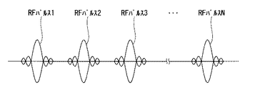
図3は、第1の実施形態に係るRFパルスの第1の送信順序を説明する図である。図3は同じ強度のRFパルスが連続して送信される例を示している。図3の左からRFパルス1、RFパルス2、RFパルス3...RFパルスNが順に送信され、N回のRFパルスが送信される例を示している。それぞれのRFパルスはパルスシーケンス実行データに規定された所定の間隔毎に出力される。
FIG. 3 is a diagram for explaining a first transmission order of RF pulses according to the first embodiment. FIG. 3 shows an example in which RF pulses of the same intensity are transmitted continuously.
以下、図3に示したRFパルスの出力順序に基づいて第1の実施形態に係る動作を説明する。 The operation according to the first embodiment will be described below based on the output order of the RF pulses shown in FIG.
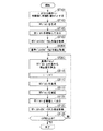
図4は、第1の実施形態に係る動作の一例を示すフローチャートである。 FIG. 4 is a flowchart showing an example of the operation according to the first embodiment.
ST101では、シーケンサ30がパルスシーケンス実行データからパルス出力順序を取得する。図3に示したN回のRFパルスを順に出力する場合、パルス出力順序iの初期値を1、終値をNとして、iが1ずつ増加する。
In ST101, the
ST103では、RFパルス発生器41がRFパルスを発生させる。
In ST103, the
ST105では、RFアンプ43がRFパルスを増幅し送信コイル26に出力する。
At ST 105, the
ST107では、ピーク値取得部47が送信されたRFパルスのピーク出力値を取得する。
In ST107, the peak
ST109では、補正値算出部48がRFパルスが2回以上送信されたかを判断する。補正値算出部48は、たとえば、ピーク値取得部47で取得されたピーク値が2つ以上存在する場合、2回以上送信されたと判断する。2回以上送信されたと判断された場合(Yes)は、ST113以降で補正値が算出される。一方、2回以上送信されていないと判断された場合(No)は、ST103で次の順序のRFパルスが生成される。
In ST109, the correction
ST111では、補正値算出部48おいて最初に送信されるRFパルスを基準パルスとして、基準パルスのピーク出力値と、基準パルスの後に送信されたRFパルスのピーク出力値との差を求め、補正値を算出する。
In ST111, using the RF pulse transmitted first in the correction
図3の例を用いて具体的に説明すると、RFパルス1が送信されるとピーク値取得部47によりピーク出力値1が取得される。補正値算出部48は、RFパルス1のピーク出力値1しか存在しないため(ST109No)、補正値の算出は行わない。次に送信されるRFパルス2が送信されるとピーク値取得部47によりピーク出力値2が取得される。この場合、RFパルス1のピーク出力値1とRFパルス2のピーク出力値2が存在するため(ST109Yes)、補正値算出部48は補正値を算出できる。
If it demonstrates concretely using the example of FIG. 3, when
たとえば、RFパルス1のピーク出力値1をA1、RFパルス2のピーク出力値2をA2とすると、補正値Cは下記の式により求められる。
補正値C=A1/A2・・・(1)
For example, assuming that the
Correction value C = A1 / A2 (1)
上述の式により求めた補正値をRFパルスに乗じて、振幅値(ピーク値)を補正することができる。補正値算出部48で補正値が算出されたら、算出された補正値により次に発生するRFパルスの補正を行う。
The amplitude value (peak value) can be corrected by multiplying the RF pulse by the correction value obtained by the above equation. After the correction value is calculated by the
ST115では、シーケンサ30が次の順序(i+1)のRFパルスを発生させるよう、RFパルス発生器41に指示する。図3の例では、RFパルス3が出力される。
In ST115, the
ST117では、RFパルス発生器41がRFパルスを発生させる。
At ST117, the
ST119では、補正部52がRFパルス発生器41で発生したRFパルスを補正する。
In ST119, the
ST121では、補正したRFパルスを増幅して送信コイル26に出力する。 In ST121, the corrected RF pulse is amplified and output to the transmission coil.
ST123では、ピーク値取得部47が送信されたRFパルスのピーク出力値を取得する。
In ST123, the peak
ST125では、シーケンサ30がパルスシーケンス実行データに設定されたRFパルスがすべて送信されたか否かが判断される。設定されたRFパルスがすべて送信されていない場合(ST125No)、基準パルスのピーク出力値と新たに取得されたピーク出力値との差から補正値が算出される(ST113)。具体的には、図3のRFパルス3のピーク出力値と、基準パルスに設定されたRFパルス1のピーク出力値とから補正値が算出される。一方、設定されたRFパルスがすべて送信された場合(ST125Yes)、すなわち、図3の例でRFパルスNまで送信された場合は処理が終了する。
At ST125, it is determined whether all the RF pulses set in the pulse sequence execution data by the
上述のように、出力されたRFパルス(図3の例ではRFパルス1)を基準パルスとして、基準パルスの後に出力されたRFパルスのピーク出力値と、基準パルスのピーク出力値とを比較し補正値を算出することで、新たに出力されるRFパルスを補正する。
As described above, using the output RF pulse (
このように、基準パルスに基づいて出力されるRFパルスを補正することにより、基準パルス以降のRFパルスの出力がRFアンプ43の温度変化によるゲイン変動で変化することを抑制することができ、所望の出力のRFパルスを送信することができる。また、RFパルスを基準パルスと同じ強度で出力することができるため、RFパルス強度のムラが低減し、取得した画像のアーチファクトを予防することができる。
As described above, by correcting the RF pulse output based on the reference pulse, it is possible to suppress the change of the output of the RF pulse after the reference pulse due to the gain fluctuation due to the temperature change of the
なお、図4のフローチャートの例では、撮像プロトコル毎に設定されたパルスシーケンス単位で基準パルスを設定する例を示したが、基準パルスの設定はパルスシーケンス単位に限られない。たとえば、1つの検査は複数の撮像プロトコルから成り、複数のパルスシーケンスが実行される。そこで、検査単位で基準パルスを設定してもよい。また、被検体毎に基準パルスを設定してもよいし、所定の間隔で基準パルスを設定してもよい。 In the example of the flowchart of FIG. 4, the reference pulse is set in units of pulse sequences set for each imaging protocol, but the setting of reference pulses is not limited to the unit of pulse sequences. For example, one exam consists of multiple imaging protocols and multiple pulse sequences are performed. Therefore, the reference pulse may be set in inspection units. Also, a reference pulse may be set for each subject, or may be set at a predetermined interval.
また、基準パルスと最初の補正値を算出するためのRFパルスは、撮像に使用しない補正用のパルスとして出力されてもよい。このように補正後のRFパルスのみを使用することで、より安定したRFパルスの出力により画像を取得することが可能である。 Further, the RF pulse for calculating the reference pulse and the first correction value may be output as a correction pulse not used for imaging. By using only the corrected RF pulse in this manner, it is possible to acquire an image with more stable RF pulse output.
図3および図4では、出力されるRFパルスが1種類の場合を説明した。しかしながら、撮像プロトコルによっては複数の強度のRFパルスが送信される。たとえば、スピンエコー(SE:spin echo)法では、90°励起パルスと、180°再収束パルスの2種類のRFパルス強度のRFパルスを使用する。このようなパルスシーケンスでは、それぞれのRFパルスを上述の方法で補正する。 In FIG. 3 and FIG. 4, the case where one type of RF pulse was output was demonstrated. However, depending on the imaging protocol, multiple intensities of RF pulses may be transmitted. For example, spin echo (SE: spin echo) method uses RF pulses of two types of RF pulse strength: 90 ° excitation pulse and 180 ° refocusing pulse. In such a pulse sequence, each RF pulse is corrected in the manner described above.
図5は、第1の実施形態に係るRFパルスの第2の送信順序を説明する図である。図5は、左から、RFパルスAとRFパルスBの2種類が順番に送信される例を示しており、たとえば、90°励起パルスと、180°再収束パルスの2種類のRFパルス強度のRFパルスを送信する場合に当てはまる。 FIG. 5 is a diagram for explaining a second transmission order of RF pulses according to the first embodiment. FIG. 5 shows an example in which two types of RF pulse A and RF pulse B are transmitted in order from the left, and for example, two types of RF pulse strengths of 90 ° excitation pulse and 180 ° refocusing pulse are shown. This is the case when transmitting an RF pulse.
図5は、左からRFパルスA1、RFパルスB1、RFパルスA2、RFパルスB2、RFパルスA3、RFパルスB3...RFパルスAN、RFパルスBNが順に送信され、RFパルスAとRFパルスBがN回ずつ送信される例を示している。 FIG. 5 shows, from the left, an RF pulse A1, an RF pulse B1, an RF pulse A2, an RF pulse B2, an RF pulse A3, an RF pulse B3. . . An example is shown in which an RF pulse AN and an RF pulse BN are sequentially transmitted, and an RF pulse A and an RF pulse B are transmitted N times each.
図5のように異なる強度のRFパルスが送信される場合は、それぞれのパルスについてピーク値が取得され、それぞれのパルスについて基準パルスが設定され、補正値が算出される。具体的には、図5の例では、RFパルスA1とRFパルスB1が基準パルスとして設定される。基準パルスの後に出力されるRFパルスA2のピーク出力値と基準パルス(RFパルスA1)のピーク出力値とを比較し、補正値CA1を算出する。同様に、RFパルスB2のピーク出力値と基準パルス(RFパルスB1)のピーク出力値とを比較し、補正値CB1を算出する。算出された補正値CA1でRFパルスA3を補正し、補正値CB1でRFパルスB3を補正する。 When RF pulses of different intensities are transmitted as shown in FIG. 5, peak values are obtained for each pulse, a reference pulse is set for each pulse, and a correction value is calculated. Specifically, in the example of FIG. 5, the RF pulse A1 and the RF pulse B1 are set as reference pulses. The peak output value of the RF pulse A2 output after the reference pulse is compared with the peak output value of the reference pulse (RF pulse A1) to calculate a correction value CA1. Similarly, the peak output value of the RF pulse B2 and the peak output value of the reference pulse (RF pulse B1) are compared to calculate the correction value CB1. The RF pulse A3 is corrected by the calculated correction value CA1, and the RF pulse B3 is corrected by the correction value CB1.
このように同じ強度のパルス同士を比較して、それぞれのパルス強度で補正値を算出し、新たに出力される同じ強度のパルスを補正する。 As described above, the pulses having the same intensity are compared with each other, the correction value is calculated with each pulse intensity, and the newly output pulse having the same intensity is corrected.
図5では、補正値算出部48が、それぞれのパルス種別(たとえば、90°励起パルスと180°再収束パルス)を区別可能な場合を例示しているが、たとえば、パルス強度の差からパルス種別を区別することができる。しかしながらパルス種別が異なる場合であっても、パルス強度が近いRFパルスが出力される場合、ピーク出力値だけでは異なるパルスであるか判断できない場合がある。一方、シーケンサ30に記憶されているパルスシーケンス実行データを用いれば、出力されるパルス強度やタイミングなどを判別することができる。また、パルスシーケンス実行データを使用しなくとも、入力部36などから、ユーザがパルスの種類数や出力順序などを入力することで、それぞれのパルスを区別することができる。このように、補正値算出部48はそれぞれのパルスを区別可能な場合のみ補正値を算出するようにしてもよい。また、補正部49は、それぞれのパルスを区別できないとき、誤った補正を回避するため補正を実行しないようにしてもよい。
Although FIG. 5 exemplifies a case where the correction
また、RFパルスの出力間隔が所定の閾値より大きい場合、補正部49は、補正を実行しないようにしてもよい。RFパルスの出力間隔が大きい場合、補正値を算出したタイミングと、補正対象のRFパルスを出力するタイミングとでは状況が異なる場合がある。たとえば、RFパルス強度がRFアンプ43により十分に増幅されず、基準パルスの強度より小さかった場合、補正値は強度を大きくするように設定される。次に出力される補正対象のRFパルス強度がRFアンプ43により所望のゲインより大きく増幅された場合、補正値はRFパルスを大きくするように設定されているため、所望のゲインよりかなり大きく出力されてしまう。このような補正が繰り返されると、RFパルスは徐々に大きくなり、最後には発振する。補正部52は発振が発生しないように、RFパルスの出力間隔が所定の閾値より大きい場合は補正を行わないようにしてもよい。
In addition, when the output interval of the RF pulse is larger than the predetermined threshold, the
このように、送信コイル26に出力されたRFパルス強度に基づいて補正値を算出し、RFアンプ43に入力されるRFパルスを補正することで、スキャン中に刻々と変化するRFアンプ43の温度による影響を受けないフィードバック制御を行うことができる。
As described above, the correction value is calculated based on the RF pulse intensity output to the
(第2の実施形態)
第2の実施形態は、基準パルスを予め記憶しておき、記憶した基準パルスと出力した第2のRFパルスとを比較して補正値を算出する方法に関する。
Second Embodiment
The second embodiment relates to a method of storing a reference pulse in advance and comparing the stored reference pulse with the output second RF pulse to calculate a correction value.
図6は、第2の実施形態に係る動作の一例を示すフローチャートである。図4のフローチャートと同一の処理については同一の符号を付して説明を省略する。 FIG. 6 is a flowchart showing an example of the operation according to the second embodiment. The same processes as those in the flowchart of FIG.
ST201では、補正値算出部48が基準パルス記憶部51から基準パルスのピーク出力値を取得する。基準パルスのピーク出力値は、たとえば、パルスシーケンス実行データに設定されたRFパルス強度などから計算された予測値である。
In ST201, the correction
ST203では、補正値算出部48が、基準パルスのピーク出力値と、送信コイル26に送信されたRFパルスのピーク出力値の差から補正値を算出する。
In ST203, the correction
たとえば、図3のようにRFパルスが出力される場合、基準パルスのピーク出力値とRFパルス1のピーク出力値とから最初の補正値を算出することができる。第1の実施形態では一番初めに実際に出力されたRFパルスが異常値である場合、その後の補正は異常値に基づいて実施されるため適当でない。第2の実施形態では、基準パルスを予め記憶しておくため、たとえば、正常な条件で取得した値を基準パルスとして設定することもでき、誤った補正を回避することができる。
For example, when the RF pulse is output as shown in FIG. 3, the first correction value can be calculated from the peak output value of the reference pulse and the peak output value of the
また、図5で示すように異なるRFパルス強度を出力する場合も、それぞれの強度の基準パルスを記憶しておくことで補正することができる。さらに、撮像プロトコル毎に使用するRFパルスは異なるため、撮像プロトコル毎に規定されたパルスシーケンス実行データに応じて、基準パルスを記憶していてもよい。 In addition, as shown in FIG. 5, even when different RF pulse intensities are output, correction can be performed by storing reference pulses of the respective intensities. Furthermore, since the RF pulses used for each imaging protocol are different, reference pulses may be stored according to pulse sequence execution data defined for each imaging protocol.
なお、第1の実施形態や第2の実施形態で算出される補正値は、補正値記憶部49に記憶しておいてもよい。
The correction value calculated in the first embodiment or the second embodiment may be stored in the correction
図7は、第1の実施形態に係る補正値テーブルを説明する図である。図7の表は、RFパルス強度の違うパルス種別毎に「校正時補正値」、「動作中補正値」が記憶されている。「校正時補正値」は、検査前に行われる自動パワー制御により設定されたゲインのことである。「実行中補正値」は、上述の実施形態で算出される補正値のことである。 FIG. 7 is a diagram for explaining the correction value table according to the first embodiment. In the table of FIG. 7, “calibration correction value” and “operation correction value” are stored for each pulse type having different RF pulse intensity. The “calibration correction value” is a gain set by automatic power control performed before inspection. The "correction value during execution" is the correction value calculated in the above-described embodiment.
図7の例では、RFパルス種別が90°パルスの場合、校正時補正値は0.9、動作中補正値は0.8である。同様にRFパルス種別が180°パルスの場合は、校正時補正値は、1.2、動作中補正値は1.8である。RFパルス種別がα°パルスの場合は校正時補正値は、1.1、動作中補正値は1.3である。 In the example of FIG. 7, when the RF pulse type is a 90 ° pulse, the calibration correction value is 0.9, and the in-operation correction value is 0.8. Similarly, when the RF pulse type is a 180 ° pulse, the correction value at calibration is 1.2 and the correction value during operation is 1.8. When the RF pulse type is α ° pulse, the calibration correction value is 1.1, and the in-operation correction value is 1.3.
RFパルスはパルス種別毎に標準的なゲインを予め備えており、検査前の自動パワー制御により補正され、さらに本実施形態で算出される補正値が算出されている場合は、動作中補正値によって補正される。パルス種別毎の標準的ゲインは、パルス種別毎に設定されていてもよいし、あるパルス種別を基準として設定されていてもよい。パルス種別毎の設定は、MRI装置10毎に予め設定されていてもよいし、据え付け時などにMRI装置10で測定した結果を設定してもよい。
The RF pulse has a standard gain in advance for each pulse type, is corrected by automatic power control before the test, and if the correction value calculated in this embodiment is calculated, the operating correction value is used. It is corrected. The standard gain for each pulse type may be set for each pulse type, or may be set based on a certain pulse type. The setting for each pulse type may be set in advance for each
補正値記憶部49は、補正値算出部48で補正値が算出されるたびに補正値を更新してもよいし、算出されたすべての補正値を記憶していてもよい。
The correction
このように補正値を記憶しておくことで、たとえば、第2の実施形態で用いる基準パルスの予測値の算出に使用できる。また、継時的に補正値を蓄積することで、RFアンプ43の冷却装置53の点検に使用することもできる。上述のように取得した補正値は、RFアンプ43の冷却装置53の外から取得される情報であり、冷却装置53の影響を受けない数値である。したがって、冷却装置53自体で取得される情報で異常を発見できない場合でも、補正値の推移を分析することで異常を発見することが可能となる。
By storing the correction value in this manner, it can be used, for example, to calculate the predicted value of the reference pulse used in the second embodiment. Further, by accumulating the correction value over time, it can also be used for inspection of the
以上説明した少なくともひとつの実施形態のMRI装置によれば、所望のRFパルス強度を出力できる。 According to the MRI apparatus of at least one embodiment described above, desired RF pulse intensity can be output.
本発明のいくつかの実施形態を説明したが、これらの実施形態は、例として提示したものであり、発明の範囲を限定することは意図していない。これら実施形態は、その他の様々な形態で実施されることが可能であり、発明の要旨を逸脱しない範囲で、種々の省略、置き換え、変更を行うことができる。これら実施形態やその変形は、発明の範囲や要旨に含まれると同様に、特許請求の範囲に記載された発明とその均等の範囲に含まれるものである。 While certain embodiments of the present invention have been described, these embodiments have been presented by way of example only, and are not intended to limit the scope of the invention. These embodiments can be implemented in other various forms, and various omissions, replacements, and modifications can be made without departing from the scope of the invention. These embodiments and modifications thereof are included in the invention described in the claims and the equivalents thereof as well as included in the scope and the gist of the invention.
10 MRI装置
11 撮像システム
12 制御システム
21 静磁場磁石
22 傾斜磁場コイル
23 傾斜磁場電源装置
24 寝台
24a 天板
25 寝台制御部
26 送信コイル
27 増幅部
28a〜e 受信コイル
29 受信部
30 シーケンサ
31 インターフェース部
32 データ収集部
33 データ処理部
34 記憶部
35 表示部
36 入力部
37 制御部
41 RFパルス発生器
42 D/A変換器
43 RFアンプ
44 方向性結合器
45 検波器
46 A/D変換器
47 ピーク値取得部
48 補正値算出部
49 補正値記憶部
51 基準パルス記憶部
52 補正部
53 冷却装置
DESCRIPTION OF
Claims (13)
前記RFパルス発生器から順次入力されるRFパルスを夫々増幅する増幅部と、
増幅後のRFパルスが前記増幅部から出力されるごとに、当該増幅後のRFパルスのピーク出力値を取得するピーク値取得部と、
前記増幅後のRFパルスのピーク出力値と基準ピーク出力値とに基づいて、補正値を算出する補正値算出部と、
前記RFパルス列に含まれる後段のRFパルスであって、前記増幅部に入力される前のRFパルスに前記補正値を即時に適用する補正部と、
を備え、
前記補正値算出部は、
前記基準ピーク出力値として、前記RFパルス列の先頭のRFパルスのピーク出力値を設定する、
MRI装置。 An RF pulse generator that sequentially generates an RF pulse train defined in the pulse sequence;
An amplification unit configured to respectively amplify RF pulses sequentially input from the RF pulse generator;
A peak value acquisition unit that acquires a peak output value of the amplified RF pulse each time the amplified RF pulse is output from the amplification unit;
A correction value calculation unit that calculates a correction value based on the peak output value of the amplified RF pulse and the reference peak output value;
A correction unit that immediately applies the correction value to an RF pulse at a subsequent stage included in the RF pulse train and before being input to the amplification unit;
Equipped with
The correction value calculation unit
The peak output value of the first RF pulse of the RF pulse train is set as the reference peak output value.
MRI device.
前記RFパルス発生器から順次入力されるRFパルスを夫々増幅する増幅部と、
増幅後のRFパルスが前記増幅部から出力されるごとに、当該増幅後のRFパルスのピーク出力値を取得するピーク値取得部と、
前記増幅後のRFパルスのピーク出力値と基準ピーク出力値とに基づいて、補正値を算出する補正値算出部と、
前記RFパルス列に含まれる後段のRFパルスであって、前記増幅部に入力される前のRFパルスに前記補正値を即時に適用する補正部と、
を備え、
前記補正値算出部は、
前記パルスシーケンスを実行中の所定の期間毎に前記基準ピーク出力値を更新する、
MRI装置。 An RF pulse generator that sequentially generates an RF pulse train defined in the pulse sequence;
An amplification unit configured to respectively amplify RF pulses sequentially input from the RF pulse generator;
A peak value acquisition unit that acquires a peak output value of the amplified RF pulse each time the amplified RF pulse is output from the amplification unit;
A correction value calculation unit that calculates a correction value based on the peak output value of the amplified RF pulse and the reference peak output value;
A correction unit that immediately applies the correction value to an RF pulse at a subsequent stage included in the RF pulse train and before being input to the amplification unit;
Equipped with
The correction value calculation unit
Updating the reference peak output value at predetermined intervals during execution of the pulse sequence;
MRI device.
前記RFパルス発生器から順次入力されるRFパルスを夫々増幅する増幅部と、
増幅後のRFパルスが前記増幅部から出力されるごとに、当該増幅後のRFパルスのピーク出力値を取得するピーク値取得部と、
前記増幅後のRFパルスのピーク出力値と基準ピーク出力値とに基づいて、補正値を算出する補正値算出部と、
前記RFパルス列に含まれる後段のRFパルスであって、前記増幅部に入力される前のRFパルスに前記補正値を即時に適用する補正部と、
を備え、
前記補正値算出部は、
前記増幅部から出力された増幅後のRFパルスのうち、いずれかを基準パルスに設定し、前記基準パルスのピーク出力値と、前記基準パルスの後に前記増幅部から出力された増幅後のRFパルスのピーク出力値との差から前記補正値を算出する、
MRI装置。 An RF pulse generator that sequentially generates an RF pulse train defined in the pulse sequence;
An amplification unit configured to respectively amplify RF pulses sequentially input from the RF pulse generator;
A peak value acquisition unit that acquires a peak output value of the amplified RF pulse each time the amplified RF pulse is output from the amplification unit;
A correction value calculation unit that calculates a correction value based on the peak output value of the amplified RF pulse and the reference peak output value;
A correction unit that immediately applies the correction value to an RF pulse at a subsequent stage included in the RF pulse train and before being input to the amplification unit;
Equipped with
The correction value calculation unit
One of the amplified RF pulses output from the amplification unit is set as a reference pulse, and the peak output value of the reference pulse and the amplified RF pulse output from the amplification unit after the reference pulse Calculating the correction value from the difference between the
MRI device.
前記RFパルス発生器から順次入力されるRFパルスを夫々増幅する増幅部と、
増幅後のRFパルスが前記増幅部から出力されるごとに、当該増幅後のRFパルスのピーク出力値を取得するピーク値取得部と、
前記増幅後のRFパルスのピーク出力値と基準ピーク出力値とに基づいて、補正値を算出する補正値算出部と、
前記RFパルス列に含まれる後段のRFパルスであって、前記増幅部に入力される前のRFパルスに前記補正値を即時に適用する補正部と、
基準パルスの前記基準ピーク出力値を予め記憶している基準パルス記憶部と、
を備え、
前記補正値算出部は、
前記増幅後のRFパルスのピーク出力値と、前記基準パルス記憶部に記憶された前記基準ピーク出力値との差から前記補正値を算出する、
MRI装置。 An RF pulse generator that sequentially generates an RF pulse train defined in the pulse sequence;
An amplification unit configured to respectively amplify RF pulses sequentially input from the RF pulse generator;
A peak value acquisition unit that acquires a peak output value of the amplified RF pulse each time the amplified RF pulse is output from the amplification unit;
A correction value calculation unit that calculates a correction value based on the peak output value of the amplified RF pulse and the reference peak output value;
A correction unit that immediately applies the correction value to an RF pulse at a subsequent stage included in the RF pulse train and before being input to the amplification unit;
A reference pulse storage unit in which the reference peak output value of the reference pulse is stored in advance;
Equipped with
The correction value calculation unit
The correction value is calculated from the difference between the peak output value of the amplified RF pulse and the reference peak output value stored in the reference pulse storage unit.
MRI device.
前記補正値算出部は、前記第1出力値のRFパルス及び前記第2出力値のRFパルスのそれぞれに対応する第1基準ピーク出力値及び第2基準ピーク出力値を設定し、
前記基準パルス記憶部は、前記第1基準ピーク出力値及び前記第2基準ピーク出力値を予め記憶し、
前記補正値算出部は、前記基準パルス記憶部に記憶された前記第1基準ピーク出力値及び前記第2基準ピーク出力値を用いる、
請求項4記載のMRI装置。 The RF pulse generator generates the RF pulse train including an RF pulse of a first output value and an RF pulse of a second output value, and inputs the RF pulse train to the amplification unit.
The correction value calculation unit sets a first reference peak output value and a second reference peak output value corresponding to each of the RF pulse of the first output value and the RF pulse of the second output value,
The reference pulse storage unit stores in advance the first reference peak output value and the second reference peak output value,
The correction value calculation unit uses the first reference peak output value and the second reference peak output value stored in the reference pulse storage unit.
The MRI apparatus according to claim 4.
請求項4記載のMRI装置。 The reference pulse storage unit stores the reference peak output value for each type of pulse sequence.
The MRI apparatus according to claim 4.
前記RFパルス発生器から順次入力されるRFパルスを夫々増幅する増幅部と、
増幅後のRFパルスが前記増幅部から出力されるごとに、当該増幅後のRFパルスのピーク出力値を取得するピーク値取得部と、
前記増幅後のRFパルスのピーク出力値と基準ピーク出力値とに基づいて、補正値を算出する補正値算出部と、
前記RFパルス列に含まれる後段のRFパルスであって、前記増幅部に入力される前のRFパルスに前記補正値を即時に適用する補正部と、
を備え、
前記RFパルス発生器は、
第1出力値のRFパルスと第2出力値のRFパルスとを含む前記RFパルス列を発生させて前記増幅部に入力し、
前記補正値算出部は、
前記第1出力値のRFパルス及び前記第2出力値のRFパルスのそれぞれに対応する第1基準ピーク出力値及び第2基準ピーク出力値を設定し、前記第1出力値のRFパルスに対応する増幅後のRFパルスのピーク出力値と、前記第1基準ピーク出力値との差から第1の補正値を算出し、前記第2出力値のRFパルスに対応する増幅後のRFパルスのピーク出力値と、前記第2基準ピーク出力値との差から第2の補正値を算出し、
前記補正部は、
前記第1の補正値を前記RFパルス列に含まれる後段のRFパルスであって、前記増幅部に入力される前の前記第1出力値のRFパルスに適用し、前記第2の補正値を前記RFパルス列に含まれる後段のRFパルスであって、前記増幅部に入力される前の前記第2出力値のRFパルスに適用する、
MRI装置。 An RF pulse generator that sequentially generates an RF pulse train defined in the pulse sequence;
An amplification unit configured to respectively amplify RF pulses sequentially input from the RF pulse generator;
A peak value acquisition unit that acquires a peak output value of the amplified RF pulse each time the amplified RF pulse is output from the amplification unit;
A correction value calculation unit that calculates a correction value based on the peak output value of the amplified RF pulse and the reference peak output value;
A correction unit that immediately applies the correction value to an RF pulse at a subsequent stage included in the RF pulse train and before being input to the amplification unit;
Equipped with
The RF pulse generator is
Generating an RF pulse train including an RF pulse of a first output value and an RF pulse of a second output value, and inputting the RF pulse train to the amplification unit;
The correction value calculation unit
A first reference peak output value and a second reference peak output value corresponding to each of the RF pulse of the first output value and the RF pulse of the second output value are set, and correspond to the RF pulse of the first output value. A first correction value is calculated from the difference between the peak output value of the amplified RF pulse and the first reference peak output value, and the peak output of the amplified RF pulse corresponding to the RF pulse of the second output value Calculating a second correction value from the difference between the value and the second reference peak output value;
The correction unit is
The first correction value is applied to an RF pulse of a later stage included in the RF pulse train, the RF pulse of the first output value before being input to the amplification unit, and the second correction value is the second correction value. The present invention is applied to an RF pulse of a second stage included in an RF pulse train and before being input to the amplification unit.
MRI device.
請求項7に記載のMRI装置。 The correction value calculation unit sets one of the peak output values of the amplified RF pulse corresponding to the RF pulse of the first output value as the first reference peak output value, and the RF of the second output value. Setting one of the peak output values of the amplified RF pulse corresponding to the pulse to the second reference peak output value;
The MRI apparatus according to claim 7.
前記RFパルス発生器から順次入力されるRFパルスを夫々増幅する増幅部と、
増幅後のRFパルスが前記増幅部から出力されるごとに、当該増幅後のRFパルスのピーク出力値を取得するピーク値取得部と、
前記増幅後のRFパルスのピーク出力値と基準ピーク出力値とに基づいて、補正値を算出する補正値算出部と、
前記RFパルス列に含まれる後段のRFパルスであって、前記増幅部に入力される前のRFパルスに前記補正値を即時に適用する補正部と、
を備え、
前記補正値算出部は、
複数の撮像プロトコルを備えた1つの検査毎、または撮像プロトコル毎に前記基準ピーク出力値を設定する、
MRI装置。 An RF pulse generator that sequentially generates an RF pulse train defined in the pulse sequence;
An amplification unit configured to respectively amplify RF pulses sequentially input from the RF pulse generator;
A peak value acquisition unit that acquires a peak output value of the amplified RF pulse each time the amplified RF pulse is output from the amplification unit;
A correction value calculation unit that calculates a correction value based on the peak output value of the amplified RF pulse and the reference peak output value;
A correction unit that immediately applies the correction value to an RF pulse at a subsequent stage included in the RF pulse train and before being input to the amplification unit;
Equipped with
The correction value calculation unit
Setting the reference peak output value for each examination with a plurality of imaging protocols or for each imaging protocol,
MRI device.
前記RFパルス発生器から順次入力されるRFパルスを夫々増幅する増幅部と、
増幅後のRFパルスが前記増幅部から出力されるごとに、当該増幅後のRFパルスのピーク出力値を取得するピーク値取得部と、
前記増幅後のRFパルスのピーク出力値と基準ピーク出力値とに基づいて、補正値を算出する補正値算出部と、
前記RFパルス列に含まれる後段のRFパルスであって、前記増幅部に入力される前のRFパルスに前記補正値を即時に適用する補正部と、
を備え、
前記補正値算出部は、
前記増幅部から連続して出力される2つのRFパルスの出力間隔が第1の期間より短いとき、および前記第1の期間より長い第2の期間より長いとき、の少なくとも一方のときは、前記増幅部に入力される前のRFパルスに対する前記補正値の適用を行わない、
MRI装置。 An RF pulse generator that sequentially generates an RF pulse train defined in the pulse sequence;
An amplification unit configured to respectively amplify RF pulses sequentially input from the RF pulse generator;
A peak value acquisition unit that acquires a peak output value of the amplified RF pulse each time the amplified RF pulse is output from the amplification unit;
A correction value calculation unit that calculates a correction value based on the peak output value of the amplified RF pulse and the reference peak output value;
A correction unit that immediately applies the correction value to an RF pulse at a subsequent stage included in the RF pulse train and before being input to the amplification unit;
Equipped with
The correction value calculation unit
When at least one of an output interval of two RF pulses continuously output from the amplification unit is shorter than a first period and a second period longer than the first period, The application of the correction value to the RF pulse before being input to the amplification unit is not performed.
MRI device.
請求項1乃至10のいずれか1項に記載のMRI装置。 The correction unit applies the correction value in units of RF pulses defined in the pulse sequence.
The MRI apparatus according to any one of claims 1 to 10 .
前記補正値算出部は、前記補正値を算出するたびに前記補正値記憶部に記憶された前記補正値を更新する、
請求項1乃至請求項11のいずれか1項に記載のMRI装置。 It further comprises a correction value storage unit for storing the correction value calculated by the correction value calculation unit,
The correction value calculation unit updates the correction value stored in the correction value storage unit each time the correction value is calculated.
The MRI apparatus according to any one of claims 1 to 11 .
前記補正値記憶部は、前記第1基準ピーク出力値のRFパルスに対応する補正値及び前記第2基準ピーク出力値のRFパルスに対応する補正値をそれぞれ記憶する、
請求項7または8に記載のMRI装置。 It further comprises a correction value storage unit for storing the correction value calculated by the correction value calculation unit,
The correction value storage unit stores a correction value corresponding to an RF pulse of the first reference peak output value and a correction value corresponding to an RF pulse of the second reference peak output value.
An MRI apparatus according to claim 7 or 8.
Priority Applications (2)
| Application Number | Priority Date | Filing Date | Title |
|---|---|---|---|
| JP2014156067A JP6532657B2 (en) | 2014-07-31 | 2014-07-31 | MRI apparatus |
| US14/793,964 US10353042B2 (en) | 2014-07-31 | 2015-07-08 | MRI apparatus |
Applications Claiming Priority (1)
| Application Number | Priority Date | Filing Date | Title |
|---|---|---|---|
| JP2014156067A JP6532657B2 (en) | 2014-07-31 | 2014-07-31 | MRI apparatus |
Publications (3)
| Publication Number | Publication Date |
|---|---|
| JP2016032528A JP2016032528A (en) | 2016-03-10 |
| JP2016032528A5 JP2016032528A5 (en) | 2017-08-03 |
| JP6532657B2 true JP6532657B2 (en) | 2019-06-19 |
Family
ID=55179800
Family Applications (1)
| Application Number | Title | Priority Date | Filing Date |
|---|---|---|---|
| JP2014156067A Active JP6532657B2 (en) | 2014-07-31 | 2014-07-31 | MRI apparatus |
Country Status (2)
| Country | Link |
|---|---|
| US (1) | US10353042B2 (en) |
| JP (1) | JP6532657B2 (en) |
Families Citing this family (2)
| Publication number | Priority date | Publication date | Assignee | Title |
|---|---|---|---|---|
| JP6688638B2 (en) * | 2016-03-10 | 2020-04-28 | キヤノンメディカルシステムズ株式会社 | Magnetic resonance imaging equipment |
| CN112285620A (en) * | 2019-07-24 | 2021-01-29 | 通用电气精准医疗有限责任公司 | RF transmission system and method, MRI system and pre-scanning method thereof, and storage medium |
Family Cites Families (10)
| Publication number | Priority date | Publication date | Assignee | Title |
|---|---|---|---|---|
| US4739268A (en) * | 1987-01-21 | 1988-04-19 | Kabushiki Kaisha Toshiba | RF pulse control system for a magnetic resonance imaging transmitter |
| JP3142613B2 (en) * | 1991-10-14 | 2001-03-07 | ジーイー横河メディカルシステム株式会社 | RF drive circuit in MR device |
| JPH06319716A (en) | 1993-05-14 | 1994-11-22 | Toshiba Corp | Mri apparatus |
| JPH11290288A (en) | 1998-04-09 | 1999-10-26 | Toshiba Corp | Magnetic resonance diagnostic instrument |
| JP2006153461A (en) * | 2004-11-25 | 2006-06-15 | Hitachi Ltd | Nuclear magnetic resonance measuring device |
| CN101675354A (en) * | 2007-05-04 | 2010-03-17 | 皇家飞利浦电子股份有限公司 | The RF transmitter that is used for MRI with digital feedback |
| JP5122864B2 (en) * | 2007-05-21 | 2013-01-16 | ジーイー・メディカル・システムズ・グローバル・テクノロジー・カンパニー・エルエルシー | RF coil drive circuit and MRI apparatus |
| JP5535489B2 (en) * | 2009-01-30 | 2014-07-02 | ジーイー・メディカル・システムズ・グローバル・テクノロジー・カンパニー・エルエルシー | Magnetic resonance imaging system |
| JP5542591B2 (en) * | 2009-11-12 | 2014-07-09 | 株式会社東芝 | Magnetic resonance imaging apparatus and magnetic resonance imaging method |
| JP6042148B2 (en) * | 2011-11-22 | 2016-12-14 | 東芝メディカルシステムズ株式会社 | Magnetic resonance imaging system |
-
2014
- 2014-07-31 JP JP2014156067A patent/JP6532657B2/en active Active
-
2015
- 2015-07-08 US US14/793,964 patent/US10353042B2/en active Active
Also Published As
| Publication number | Publication date |
|---|---|
| US10353042B2 (en) | 2019-07-16 |
| US20160033609A1 (en) | 2016-02-04 |
| JP2016032528A (en) | 2016-03-10 |
Similar Documents
| Publication | Publication Date | Title |
|---|---|---|
| JP5686660B2 (en) | Magnetic resonance imaging apparatus and method | |
| JP6407590B2 (en) | MRI equipment | |
| US10191131B2 (en) | Medical imaging apparatus having multiple subsystems, and operating method therefor | |
| US9933498B2 (en) | Magnetic resonance imaging apparatus and apparatus for measuring radio frequency output for the same | |
| JP7123595B2 (en) | Magnetic resonance imaging equipment and medical processing equipment | |
| KR20160038796A (en) | Operation of a medical imaging examination device comprising a plurality of subsystems | |
| KR101713650B1 (en) | Operation of a medical imaging examination device comprising a plurality of subsystems | |
| US10359487B2 (en) | Zero echo time MR imaging | |
| US9400318B2 (en) | Method for determining a control sequence with parallel transmission | |
| US10732243B2 (en) | Method and apparatus for optimization of a time progression of a magnetic resonance control sequence | |
| US20160038054A1 (en) | Method and apparatus to acquire magnetic resonance images in a session, with acquisition of a consistently valid reference scan | |
| JP2009006132A (en) | Magnetic resonance imaging apparatus | |
| CN107209235B (en) | Automatic impedance adjustment for multi-channel RF coil assembly | |
| JP6495057B2 (en) | MRI apparatus and imaging time reduction method | |
| JP6532657B2 (en) | MRI apparatus | |
| US9575146B2 (en) | Method of characterizing | |
| US20150177354A1 (en) | Magnetic resonance method and apparatus for obtaining a scout scan of a patient containing a metallic implant | |
| US20150309139A1 (en) | Method and magnetic resonance apparatus for slice-selective magnetic resonance imaging | |
| JP6407552B2 (en) | Magnetic resonance imaging system | |
| JP6621978B2 (en) | MRI equipment | |
| US20180088200A1 (en) | Method and magnetic resonance apparatus for distortion correction of acquired scan data of an examination object | |
| US10634755B2 (en) | Method and apparatus for generating corrected magnetic resonance measurement data | |
| JP5558783B2 (en) | Magnetic resonance imaging system | |
| JP6218551B2 (en) | MRI equipment | |
| CN117008031A (en) | Correction method of magnetic resonance imaging system and magnetic resonance imaging system |
Legal Events
| Date | Code | Title | Description |
|---|---|---|---|
| A711 | Notification of change in applicant |
Free format text: JAPANESE INTERMEDIATE CODE: A711 Effective date: 20160511 |
|
| A521 | Written amendment |
Free format text: JAPANESE INTERMEDIATE CODE: A523 Effective date: 20170620 |
|
| A621 | Written request for application examination |
Free format text: JAPANESE INTERMEDIATE CODE: A621 Effective date: 20170620 |
|
| A977 | Report on retrieval |
Free format text: JAPANESE INTERMEDIATE CODE: A971007 Effective date: 20180228 |
|
| A131 | Notification of reasons for refusal |
Free format text: JAPANESE INTERMEDIATE CODE: A131 Effective date: 20180306 |
|
| A521 | Written amendment |
Free format text: JAPANESE INTERMEDIATE CODE: A523 Effective date: 20180501 |
|
| A131 | Notification of reasons for refusal |
Free format text: JAPANESE INTERMEDIATE CODE: A131 Effective date: 20181002 |
|
| A521 | Written amendment |
Free format text: JAPANESE INTERMEDIATE CODE: A523 Effective date: 20181130 |
|
| TRDD | Decision of grant or rejection written | ||
| A01 | Written decision to grant a patent or to grant a registration (utility model) |
Free format text: JAPANESE INTERMEDIATE CODE: A01 Effective date: 20190423 |
|
| A61 | First payment of annual fees (during grant procedure) |
Free format text: JAPANESE INTERMEDIATE CODE: A61 Effective date: 20190522 |
|
| R150 | Certificate of patent or registration of utility model |
Ref document number: 6532657 Country of ref document: JP Free format text: JAPANESE INTERMEDIATE CODE: R150 |