JP6530159B2 - Adhesive dispensing system with metering system comprising variable frequency drive and closed loop feedback control - Google Patents
Adhesive dispensing system with metering system comprising variable frequency drive and closed loop feedback control Download PDFInfo
- Publication number
- JP6530159B2 JP6530159B2 JP2013141229A JP2013141229A JP6530159B2 JP 6530159 B2 JP6530159 B2 JP 6530159B2 JP 2013141229 A JP2013141229 A JP 2013141229A JP 2013141229 A JP2013141229 A JP 2013141229A JP 6530159 B2 JP6530159 B2 JP 6530159B2
- Authority
- JP
- Japan
- Prior art keywords
- hot melt
- melt adhesive
- flow rate
- pump
- adhesive
- Prior art date
- Legal status (The legal status is an assumption and is not a legal conclusion. Google has not performed a legal analysis and makes no representation as to the accuracy of the status listed.)
- Expired - Fee Related
Links
Images


Classifications
-
- B—PERFORMING OPERATIONS; TRANSPORTING
- B05—SPRAYING OR ATOMISING IN GENERAL; APPLYING FLUENT MATERIALS TO SURFACES, IN GENERAL
- B05C—APPARATUS FOR APPLYING FLUENT MATERIALS TO SURFACES, IN GENERAL
- B05C11/00—Component parts, details or accessories not specifically provided for in groups B05C1/00 - B05C9/00
- B05C11/10—Storage, supply or control of liquid or other fluent material; Recovery of excess liquid or other fluent material
- B05C11/1002—Means for controlling supply, i.e. flow or pressure, of liquid or other fluent material to the applying apparatus, e.g. valves
- B05C11/1007—Means for controlling supply, i.e. flow or pressure, of liquid or other fluent material to the applying apparatus, e.g. valves responsive to condition of liquid or other fluent material
- B05C11/1013—Means for controlling supply, i.e. flow or pressure, of liquid or other fluent material to the applying apparatus, e.g. valves responsive to condition of liquid or other fluent material responsive to flow or pressure of liquid or other fluent material
-
- B—PERFORMING OPERATIONS; TRANSPORTING
- B05—SPRAYING OR ATOMISING IN GENERAL; APPLYING FLUENT MATERIALS TO SURFACES, IN GENERAL
- B05C—APPARATUS FOR APPLYING FLUENT MATERIALS TO SURFACES, IN GENERAL
- B05C11/00—Component parts, details or accessories not specifically provided for in groups B05C1/00 - B05C9/00
- B05C11/10—Storage, supply or control of liquid or other fluent material; Recovery of excess liquid or other fluent material
- B05C11/1044—Apparatus or installations for supplying liquid or other fluent material to several applying apparatus or several dispensing outlets, e.g. to several extrusion nozzles
-
- B—PERFORMING OPERATIONS; TRANSPORTING
- B05—SPRAYING OR ATOMISING IN GENERAL; APPLYING FLUENT MATERIALS TO SURFACES, IN GENERAL
- B05C—APPARATUS FOR APPLYING FLUENT MATERIALS TO SURFACES, IN GENERAL
- B05C11/00—Component parts, details or accessories not specifically provided for in groups B05C1/00 - B05C9/00
- B05C11/10—Storage, supply or control of liquid or other fluent material; Recovery of excess liquid or other fluent material
- B05C11/1042—Storage, supply or control of liquid or other fluent material; Recovery of excess liquid or other fluent material provided with means for heating or cooling the liquid or other fluent material in the supplying means upstream of the applying apparatus
-
- B—PERFORMING OPERATIONS; TRANSPORTING
- B05—SPRAYING OR ATOMISING IN GENERAL; APPLYING FLUENT MATERIALS TO SURFACES, IN GENERAL
- B05C—APPARATUS FOR APPLYING FLUENT MATERIALS TO SURFACES, IN GENERAL
- B05C5/00—Apparatus in which liquid or other fluent material is projected, poured or allowed to flow on to the surface of the work
- B05C5/001—Apparatus in which liquid or other fluent material is projected, poured or allowed to flow on to the surface of the work incorporating means for heating or cooling the liquid or other fluent material
-
- Y—GENERAL TAGGING OF NEW TECHNOLOGICAL DEVELOPMENTS; GENERAL TAGGING OF CROSS-SECTIONAL TECHNOLOGIES SPANNING OVER SEVERAL SECTIONS OF THE IPC; TECHNICAL SUBJECTS COVERED BY FORMER USPC CROSS-REFERENCE ART COLLECTIONS [XRACs] AND DIGESTS
- Y02—TECHNOLOGIES OR APPLICATIONS FOR MITIGATION OR ADAPTATION AGAINST CLIMATE CHANGE
- Y02P—CLIMATE CHANGE MITIGATION TECHNOLOGIES IN THE PRODUCTION OR PROCESSING OF GOODS
- Y02P70/00—Climate change mitigation technologies in the production process for final industrial or consumer products
- Y02P70/10—Greenhouse gas [GHG] capture, material saving, heat recovery or other energy efficient measures, e.g. motor control, characterised by manufacturing processes, e.g. for rolling metal or metal working
Description
本発明は、包括的には、ホットメルト接着剤吐出機器に関し、より詳細には、ホットメルト接着剤吐出システムとともに用いる計量システムに関する。 The present invention relates generally to hot melt adhesive dispensing equipment, and more particularly to a metering system for use with a hot melt adhesive dispensing system.
ホットメルト接着剤システムは、製造及び包装において多くの用途を有する。例えば、熱可塑性ホットメルト接着剤が、カートン封止、ケース封止、トレイ形成、パレット固定、おむつ製造を含む不織布用途、及び多くの他の用途に使用されている。通常、ホットメルト接着剤は、接着剤溶融装置のタンク又はホッパ等の接着剤供給部内に収容されているか又は接着剤供給部から供給される。ホットメルト接着剤は、加熱され、溶融され、カートン、ケース又は他の物体若しくは基材にホットメルト接着剤を塗布する吐出ガン又は他のアプリケータ(塗布装置)等のディスペンサ(吐出装置)に圧送される。接着剤供給部に関して、タンク式溶融装置並びに格子液だめ式溶融装置を含む種々のタイプの溶融装置が開発されている。タンク式溶融装置では、加熱素子が、タンクの1つ又は複数の表面の温度及びタンク内部のホットメルト接着剤の温度を上げる。格子液だめ式溶融装置では、タンク又はホッパを通って移動するホットメルト接着剤が、加熱素子の格子の上で加熱され、格子から同様に加熱されている液だめへ進むにつれて溶融される。マニホールドを用いて、液体ホットメルト接着剤を複数の流れにするように方向付け、複数のホースを通して複数のディスペンサへ送出する。加熱器は、通常、接着剤供給部(タンク、格子、液だめ等)、マニホールド、ホース及びディスペンサを含む、ホットメルト接着剤システムの幾つかの構成部材に熱的に接続される。加熱器は、ホットメルト接着剤を適切な接着剤粘度及び接着剤温度に維持する。 Hot melt adhesive systems have many uses in manufacturing and packaging. For example, thermoplastic hot melt adhesives are used for carton sealing, case sealing, tray formation, pallet fastening, non-woven applications including diaper manufacturing, and many other applications. Typically, the hot melt adhesive is contained within or supplied from an adhesive supply such as a tank or hopper of the adhesive melting apparatus. The hot melt adhesive is heated, melted, and pumped to a dispenser such as a dispensing gun or other applicator that applies the hot melt adhesive to a carton, case or other object or substrate. Be done. With respect to the adhesive supply, various types of melting devices have been developed, including tank-type melting devices as well as lattice liquid-type melting devices. In a tank-type melter, the heating element raises the temperature of one or more surfaces of the tank and the temperature of the hot melt adhesive inside the tank. In a grate melter, a hot melt adhesive moving through a tank or hopper is heated above the grate of heating elements and melted as it travels from the grate to a similarly heated reservoir. A manifold is used to direct the liquid hot melt adhesive into multiple streams and deliver it through multiple hoses to multiple dispensers. The heater is usually thermally connected to several components of the hot melt adhesive system, including adhesive supplies (tanks, grids, sumps, etc.), manifolds, hoses and dispensers. The heater maintains the hot melt adhesive at the appropriate adhesive viscosity and temperature.
加えて、ホットメルト接着剤システムにおいて使用するための種々のタイプのポンプが開発されている。例えば、ピストンポンプが、ピストンを用いて油圧プランジャを移動させ、この油圧プランジャにより液体ホットメルト接着剤がホットメルト接着剤システム内を押し流される。また、液体ホットメルト接着剤を正確に計量する歯車ポンプが、逆回転歯車を用いて容積式移送をもたらす。ポンプは、液体ホットメルト接着剤を、ホットメルト接着剤システム内を通して移動させる。これは、液体ホットメルト接着剤を、ホースを通して移動させること及び物体に塗布するためにディスペンサへ移動させることを含む。 In addition, various types of pumps have been developed for use in hot melt adhesive systems. For example, a piston pump uses a piston to move a hydraulic plunger that forces liquid hot melt adhesive to flow through the hot melt adhesive system. Also, a gear pump that accurately meters the liquid hot melt adhesive provides positive displacement transfer using counter-rotating gears. The pump moves the liquid hot melt adhesive through the hot melt adhesive system. This involves moving the liquid hot melt adhesive through a hose and moving it to a dispenser for application to an object.
ホットメルト接着剤吐出システムにおけるホットメルト接着剤の流量を監視又は制御する計量システムが開発されている。一般的な従来の計量システムでは、例えば、1つ又は複数の材料供給ポンプを用いて、ホットメルト接着剤を圧送するとともに塗布地点に送出する。例えば、ホットメルト接着剤の供給部において又は供給部付近(ホットメルト接着剤を収容する液だめ付近等)に概ね位置決めされるとともに、排出ポンプと呼ばれる1つの材料供給ポンプが、当該技術分野において遠隔計量ステーションと呼ばれる場合がある下流側計量ステーションに加圧ホットメルト接着剤を供給する。幾つかの場合では、ホットメルト接着剤の流れを、ホースを通してディスペンサに送出するために複数の流れに分流するマニホールドが、遠隔計量ステーションに備わっている。ホットメルト接着剤を圧送する上で役立つ別の材料供給ポンプが、遠隔計量ステーションに備わっていてもよいし、又は、排出ポンプと遠隔計量ステーションとの間に備わっていてもよい。2つのポンプを有するそのような構成では、排出ポンプを閉ループフィードバックシステムに連結することができるのに対し、下流側材料供給ポンプを開ループフィードバックシステムに連結することができる。 Metering systems have been developed to monitor or control the flow of hot melt adhesive in a hot melt adhesive dispensing system. In a typical prior art metering system, for example, one or more material supply pumps are used to pump and deliver the hot melt adhesive to the application point. For example, one material supply pump, generally positioned at or near the supply of the hot melt adhesive (e.g., near a reservoir containing the hot melt adhesive), is referred to as remote in the art. The pressurized hot melt adhesive is supplied to a downstream weighing station, which may be referred to as a weighing station. In some cases, a remote metering station is provided with a manifold that divides the flow of hot melt adhesive into multiple streams for delivery through a hose to a dispenser. Another material supply pump may be provided at the remote metering station, or may be provided between the discharge pump and the remote metering station, which serves to pump the hot melt adhesive. In such an arrangement having two pumps, the discharge pump can be coupled to the closed loop feedback system, while the downstream material supply pump can be coupled to the open loop feedback system.
一般的に、閉ループフィードバックシステムは、出力に影響を及ぼす変数を調整するためにプロセス出力のフィードバックを用いるプロセス制御法である。対照的に、開ループフィードバックシステムは、出力フィードバックを用いないプロセス制御法である。例えば、上述した従来の計量システムでは、排出ポンプは、排出ポンプからの流量を測定する下流側流量センサすなわち計量器に連結することができる。測定された流量は、排出ポンプに連結されたコントローラによって考慮され、コントローラは、測定された流量に応じて排出ポンプを調整する。例えば、コントローラは、排出ポンプからのホットメルト接着剤の流量を変更するために、排出ポンプが動作する速度を増減させることができる。下流側材料供給ポンプは、閉ループフィードバックシステムに必ずしも連結されない場合があり、その場合、下流側材料供給ポンプからの流れは測定されず、ポンプは、測定された流量に応じて調整されない。下流側材料供給ポンプからの出力流量が測定されないことによって、下流側材料供給ポンプから塗布地点へと流れるホットメルト接着剤の実際の流量に関する情報が収集されない。 In general, a closed loop feedback system is a process control method that uses process output feedback to adjust variables that affect the output. In contrast, open loop feedback systems are process control methods that do not use output feedback. For example, in the conventional metering system described above, the discharge pump can be coupled to a downstream flow sensor or meter that measures the flow from the discharge pump. The measured flow rate is taken into account by the controller coupled to the discharge pump, and the controller adjusts the discharge pump according to the measured flow rate. For example, the controller can increase or decrease the speed at which the discharge pump operates to change the flow rate of hot melt adhesive from the discharge pump. The downstream material feed pump may not necessarily be connected to the closed loop feedback system, in which case the flow from the downstream material feed pump is not measured and the pump is not adjusted according to the measured flow rate. By not measuring the output flow rate from the downstream material feed pump, no information is collected about the actual flow rate of the hot melt adhesive flowing from the downstream material feed pump to the application point.
閉ループフィードバックシステムを有する下流側材料供給ポンプを備える計量システムも開発されている。そのようなシステムでは、下流側材料供給ポンプのための閉ループフィードバックシステムを提供する補助コントローラ及び/又は他の補助部品が、接着剤吐出システムに導入される。例えば、ホットメルト接着剤流の流量を測定する補助センサが、材料供給ポンプに導入されるか又は材料供給ポンプの下流に導入され得る。この測定値は、補助コントローラへ送られる。補助コントローラは、次に、下流側材料供給ポンプを制御するホットメルト接着剤システムの他の制御部品と通信する。これらの他の制御部品は、次に、測定された流量がより厳密に目標流量に一致するように材料供給ポンプを調整する。補助コントローラすなわち補助部品は、計量システムに付け加えられる場合、ホットメルト接着剤吐出システムの計量システムを含む主要部品とは別個の追加の部材内に収容される。 A metering system has also been developed which comprises a downstream material feed pump with a closed loop feedback system. In such systems, an auxiliary controller and / or other auxiliary components that provide a closed loop feedback system for the downstream material supply pump are introduced into the adhesive dispensing system. For example, an auxiliary sensor that measures the flow rate of the hot melt adhesive flow can be introduced to the material supply pump or introduced downstream of the material supply pump. This measurement is sent to the auxiliary controller. The auxiliary controller then communicates with other control components of the hot melt adhesive system that controls the downstream material supply pump. These other control components then adjust the material supply pump so that the measured flow rate more closely matches the target flow rate. The supplemental controller or components, when added to the metering system, are contained within additional components separate from the main components including the metering system of the hot melt adhesive dispensing system.
他の計量システムでは、特にホットメルト接着剤の供給部が塗布地点の近くにある(例えば、離間が10メートル未満である)状況において、単一の材料供給ポンプしか使用されない。 In other metering systems, only a single material supply pump is used, particularly in situations where the supply of hot melt adhesive is close to the application point (e.g. less than 10 meters apart).
したがって、上述した欠点のうちの1つ又は複数に対処するホットメルト接着剤吐出ユニット及びこのホットメルト接着剤吐出ユニットとともに用いる計量システムが必要とされている。 Thus, there is a need for a hot melt adhesive dispensing unit and metering system for use with the hot melt adhesive dispensing unit that addresses one or more of the above mentioned disadvantages.
本発明の実施の形態は、ホットメルト接着剤吐出ユニット及びこのホットメルト接着剤吐出ユニットとともに用いられる計量システムに関する。特に、ホットメルト接着剤を複数の流れに分流するマニホールドへ供給源から当該接着剤を前進させるのに用いるポンプのための閉ループフィードバックシステムを提供する計量システムを開示する。閉ループフィードバックシステムに関連する機能部が、ホットメルト接着剤システムの主要部品に組み込まれており、補助部品が必要とされない。 Embodiments of the present invention relate to a hot melt adhesive dispensing unit and a metering system for use with the hot melt adhesive dispensing unit. In particular, a metering system is disclosed that provides a closed loop feedback system for a pump used to advance the adhesive from a source to a manifold that diverts hot melt adhesive into multiple streams. The functionality associated with the closed loop feedback system is incorporated into the main components of the hot melt adhesive system and no auxiliary components are required.
本発明の一実施の形態によれば、ホットメルト接着剤吐出ユニットは、固体又は半固体ホットメルト接着剤を収納する接着剤供給部と、前記接着剤供給部に連結され、前記固体又は半固体ホットメルト接着剤を溶融して液体ホットメルト接着剤にする接着剤供給部加熱器と、前記接着剤供給部に接続され、前記液体ホットメルト接着剤を受け取るとともに該液体ホットメルト接着剤を複数の流れに分流するマニホールドとを備える。上記ホットメルト接着剤吐出ユニットは、前記液体ホットメルト接着剤の複数の流れのうちの少なくとも1つの流れの流量を測定して流量情報を生成する流量センサと、該マニホールドに接続され、ポンプモータを含み、液体ホットメルト接着剤を前記接着剤供給部から前記マニホールドに圧送するポンプと、前記流量情報を受け取るように前記流量センサに接続されるとともに、前記ポンプモータの速度を制御するように該ポンプモータに接続される可変周波数駆動部とを更に備える。 According to one embodiment of the present invention, the hot melt adhesive dispensing unit is connected to an adhesive supply unit for containing a solid or semi-solid hot melt adhesive, and the adhesive supply unit, and the solid or semi-solid An adhesive supply heater for melting a hot melt adhesive into a liquid hot melt adhesive, and a plurality of liquid hot melt adhesives connected to the adhesive supply and receiving the liquid hot melt adhesive. And a manifold diverted to the flow. The hot melt adhesive discharge unit is connected to a flow rate sensor that measures flow rate of at least one flow of the plurality of flows of the liquid hot melt adhesive to generate flow rate information; and a pump motor connected to the manifold A pump for pumping liquid hot melt adhesive from the adhesive supply to the manifold, connected to the flow sensor to receive the flow information, and controlling the speed of the pump motor And a variable frequency drive connected to the motor.
本発明の別の実施の形態によれば、ホットメルト接着剤吐出ユニット用の計量システムは、ホットメルト接着剤を複数の流れに分流するマニホールドと、ホットメルト接着剤を前記ホットメルト接着剤吐出ユニットのタンクから前記マニホールドへ圧送するポンプと、前記ポンプに連結されたポンプモータと、前記計量システムにおけるホットメルト接着剤の流量を測定する流量センサと、前記ポンプモータを制御するように前記ポンプモータ及び前記流量センサと直接通信する可変周波数駆動部とを備える。 According to another embodiment of the present invention, a metering system for a hot melt adhesive dispensing unit comprises a manifold for diverting the hot melt adhesive into a plurality of streams; and the hot melt adhesive dispensing unit A pump for pumping from the tank to the manifold, a pump motor connected to the pump, a flow sensor for measuring the flow rate of the hot melt adhesive in the metering system, the pump motor to control the pump motor and And a variable frequency drive in direct communication with the flow sensor.
閉ループフィードバックシステムを計量システムに実装することによって、流量情報を収集するとともにホットメルト接着剤システムの他の制御部品と通信する別個の補助コントローラを用いることがなくなる。むしろ、流量センサにより収集した流量情報は、ポンプモータを制御する装置へ直接供給され、それによって、閉ループフィードバックシステムを提供する。接着剤吐出システムにおける部品の数を減らすことに加えて、計量システムは、別個の補助コントローラを用いる接着剤吐出システムと比較して接着剤吐出システムのコストを低減させる。さらに、別個の補助コントローラを排除することによって、閉ループフィードバックシステムにおいて用いられる装置の数が減り、流量測定値が収集される時とポンプ又はポンプモータが調整される時との間の遅れ時間が短くなり、それによって、システム応答が改善される。 By implementing a closed loop feedback system in the metering system, it is not necessary to use a separate auxiliary controller to collect flow rate information and to communicate with other control components of the hot melt adhesive system. Rather, the flow information collected by the flow sensor is provided directly to the device that controls the pump motor, thereby providing a closed loop feedback system. In addition to reducing the number of parts in the adhesive dispensing system, the metering system reduces the cost of the adhesive dispensing system as compared to an adhesive dispensing system that uses a separate auxiliary controller. Furthermore, by eliminating a separate auxiliary controller, the number of devices used in the closed loop feedback system is reduced and the lag time between when the flow measurement is collected and when the pump or pump motor is adjusted is short System response is improved.
本発明の様々な更なる特徴及び利点は、添付の図面と併せて例示の実施形態の以下の詳細な説明を検討すれば、当業者にはより明らかとなるであろう。 Various additional features and advantages of the present invention will become more apparent to those skilled in the art upon review of the following detailed description of the illustrated embodiments in conjunction with the accompanying drawings.
本明細書に引用されるとともに本明細書の一部をなす添付の図面は、本発明の実施形態を示し、前述した本発明の概説及び以下で述べる実施形態の詳細な説明とともに、本発明の原理を説明する役割を果たす。 BRIEF DESCRIPTION OF THE DRAWINGS The accompanying drawings, which are incorporated in and constitute a part of this specification, illustrate embodiments of the present invention and, together with the general description of the invention set forth above and the detailed description of the embodiments set forth below: It serves to explain the principle.
図面を参照すると、本発明の機能部が、ホットメルト接着剤システム10に関して示されている。ここで図示及び記載されているホットメルト接着剤システム10は、単なる例示にすぎず、本発明は、他のホットメルト接着剤システムに等しく適用可能であることが理解されるであろう。例えば、ホットメルト接着剤システム10は、接着剤供給部としてタンク式溶融装置を備えるが、本発明は、格子液だめ式溶融装置を備えるホットメルト接着剤システムにも適用可能である。
Referring to the drawings, the features of the present invention are shown with respect to a hot melt
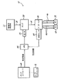
図1に最もよく見られるように、ホットメルト接着剤システム10は、固体又は半固体ホットメルト接着剤24aを収納するとともに溶融する接着剤供給部(タンク)22と、接着剤供給部22に接続されるマニホールド26と、コントローラ28と、ユーザインタフェース29とを備える吐出ユニット20を含む。溶融時、固体又は半固体ホットメルト接着剤24aは、液体ホットメルト接着剤24に変化する。接着剤供給部22は、側壁30と、取外し可能なカバー31と、接着剤供給部22内のホットメルト接着剤24a及び液体ホットメルト接着剤24を溶融及び加熱する1つ又は複数の接着剤供給部加熱器34を含む基部32とを備える。基部32は、接着剤供給部22と一体となっており、1つ又は複数の加熱器34を収容している。基部32付近の出口36は、マニホールド26の入口40につながる通路38につながっている。
As best seen in FIG. 1, the hot melt
図示のように、マニホールド26は、接着剤供給部22の側壁30に取り付けられている。縦型に配置されたピストンポンプ(図示されている)又は歯車ポンプ等のポンプ58は、マニホールド26に連結されて、液体ホットメルト接着剤24を接着剤供給部22からマニホールド26へ圧送し、そこで、液体ホットメルト接着剤24は、複数の別個の流れに分流される。ポンプ58は、ポンプモータ59に連結されている(図2)。ポンプ58、そのポンプモータ59及びマニホールド26は、ホットメルト接着剤システム10における液体ホットメルト接着剤24の流量を制御する計量システム37の機能部であり、これについては、ホットメルト接着剤システム10の概説後に以下でより詳細に説明する。図1は、マニホールド26に物理的に近接した接着剤供給部22を示しているが、ホットメルト接着剤の供給源がマニホールドから物理的に遠い他の構成も可能であり、そのような構成では、2つ以上のポンプを用いて、ホットメルト接着剤を供給源から最終的な塗布地点に向けて移動させることができることが理解されるであろう。接着剤供給部22がマニホールド26に物理的に近接している場合の計量システム37に関連する機能部は、図2に示されており、その一方、接着剤供給部22がマニホールド26から遠い場合の別の計量システム37’に関連する機能部は、図3に示されている。
As shown, the manifold 26 is attached to the sidewall 30 of the
マニホールド26は、複数の出口ポート44を含み、これらの出口ポート44には、1つ又は複数の接着剤ガン48、50へ液体ホットメルト接着剤24を供給するためにガン48、50に取り付けられた加熱ホース46が取り付けられている。加熱ホース46のそれぞれは、ホース46内の適切な温度を維持するホース加熱器46aに連結されている。図2及び図3に概略的に示されているように、マニホールド26は、加熱ホース46によってガン48、50へ搬送される流れをもたらす。ガン48、50は、物体(図示せず)へ液体ホットメルト接着剤24を吐出/塗布する1つ又は複数の接着剤吐出モジュール54を備える。接着剤吐出モジュール54は、ガン加熱器53を有するガン本体51に取り付けられており、フレーム52に支持されている。図1に示されているホットメルト接着剤システム10は、吐出ユニット20のそれぞれの側に1つずつ配置されている2つのガン48、50を備えるが、異なる数のガン、吐出モジュール及び他の構成を用いることもできる。
The manifold 26 includes a plurality of outlet ports 44 attached to the
マニホールド26は、接着剤供給部加熱器34とは別個のマニホールド加熱器56を備え、このマニホールド加熱器56は、加熱器コントローラ28によって独立して制御することができる。接着剤供給部22及びマニホールド26を加熱するのに単一の加熱器を用いることもできることが理解されるであろう。
The manifold 26 includes a manifold heater 56 separate from the adhesive supply heater 34, which can be independently controlled by the
ホットメルト接着剤システム10の加熱機能部に関して、加熱器コントローラ28は、接着剤供給部加熱器34、マニホールド加熱器56、ホース加熱器46a及びガン加熱器53を含む加熱器に電気的に接続されている。加熱器コントローラ28は、また、ホットメルト接着剤システム10における種々の温度センサに接続され、これらの温度センサは、接着剤供給部加熱器34、マニホールド加熱器56、ホース加熱器46a及びガン加熱器53に連結され、又は、それらの中に含めることができる。加熱器コントローラ28は、接着剤供給部加熱器34、マニホールド加熱器56、ホース加熱器46a及びガン加熱器53を独立して監視及び調整して、接着剤供給部22内に収納されている固体又は半固体ホットメルト接着剤24aを溶融し、また、(溶融した)液体ホットメルト接着剤24の温度を維持して、ガン48、50へ供給され接着剤吐出モジュール54によって吐出される液体ホットメルト接着剤24の適切な粘性を確保する。概して、加熱器コントローラ28は、温度センサから温度情報を受け取り、接着剤供給部加熱器34、マニホールド加熱器56、ホース加熱器46a及びガン加熱器53を含むホットメルト接着剤システム10内の加熱器のうちのいずれか又は全てを制御する等の加熱器温度制御命令を送る。加熱器制御命令は、接着剤供給部加熱器34、マニホールド加熱器56、ホース加熱器46a及びガン加熱器53を含む加熱器の温度を増減すること等によって調整する。
With respect to the heating function of the hot melt
ユーザインタフェース29は、加熱器コントローラ28に連結されており、使用者にホットメルト接着剤システム10の加熱機能についての情報及び加熱機能に対する制御を提供する。例えば、ユーザインタフェース29は、接着剤温度、加熱器温度等に関する情報を提示する。ユーザインタフェース29は、また、ホットメルト接着剤システム10の加熱に関連したパラメータを調整する制御部も備える。
The
また、図2を参照すると、計量システム37に関連する追加の機能部及び計量システム37の制御部に関連する追加の機能部が開示されている。ここでも同様に、ポンプ58は、液体ホットメルト接着剤24を、接着剤供給部22からマニホールド26へ前進させ、マニホールド26で、液体ホットメルト接着剤24は、複数の流れに分流される。マニホールド26は、液体ホットメルト接着剤24がマニホールド26を通る流量を測定する流量センサ64を備える。流量センサ64は、流量情報を生成する。例えば、流量センサ64は、液体ホットメルト接着剤24の流れにより回転するマニホールド26内の軸の回転を測定するエンコーダであってもよい。本発明に適した流量センサを備える例示的なマニホールドは、オハイオ州ウェストレイク所在のノードソンコーポレーションによりTRUFLOWという商品名で販売されている。別の例示的なマニホールドは、米国特許第6,857,441号に開示されており、この米国特許の開示内容は、この引用により本明細書の一部をなすものとする。当然のことながら、他のマニホールド、流量センサ又は流量測定装置を用いることができ、本明細書に記載されているマニホールド26及びセンサ64の具体的な形態は、単なる例示を提示している。加えて、圧力センサを流量センサ64の代わりに又は流量センサ64と併せて用いることもできる。流量センサ64は、これから説明するように、ポンプ58に連結される閉ループフィードバックシステムの一部である。
Also, referring to FIG. 2, additional features associated with the weighing
ポンプ58に連結されているポンプモータ59を制御する可変周波数駆動部(VFD)66は、計量システム37に備わっている。特に、インバータと呼ばれる場合もある可変周波数駆動部は、電気モータへ供給される電力の周波数又は電圧を制御することによってモータの回転速度を制御するシステムである。VFD66は、モータ59と通信してモータ59を制御し、本明細書に開示されている機能を達成するのに必要なハードウェア及びソフトウェアを含む。特に、VFD66は、モータ59のモータ速度を制御又は調整することができ、このモータ速度は、ポンプ58が液体ホットメルト接着剤24をホットメルト接着剤システム10内に通して圧送すなわち前進させるときの流量に影響を及ぼす。したがって、VFD66は、モータ59を制御することによって、ポンプ58により圧送される液体ホットメルト接着剤24の流量を制御する。VFD66は、また、流量センサ64と通信し、特に、流量センサ64から測定された流量情報を受け取る。
A variable frequency drive (VFD) 66 that controls the
ポンプコントローラ68は、計量システム37が設けられており、ポンプコントローラ68は、機械制御を行うように設計されており、ホットメルト接着剤システムにおける圧送の開始態様のための機能部、停止態様のための機能部及び制御態様のための機能部を備える。特に、ポンプコントローラ68は、VFD66と通信する、すなわちVFD66を制御する。ポンプコントローラ68は、計量システム37の目標接着剤流量に関連する設定点情報等の種々の制御情報をVFD66に提供する。例えば、ホットメルト接着剤システム10を通る液体ホットメルト接着剤24の流量は、特定のポンプモータ速度と関連付けられることが知られているかもしれない。操作時、コントローラ68は、制御情報をVFD66へ送り、それによって、VFD66は、目標接着剤流量に関連付けられたポンプモータ速度で動作させるようにポンプモータ59を制御する。
The
ポンプコントローラ68は、また、使用者にホットメルト接着剤システム10の圧送機能についての情報及び圧送機能に対する制御を提供するユーザインタフェース70に連結されている。ユーザインタフェース70は、接着剤流量、モータ速度及びホットメルト接着剤システム10の他の圧送に関連したパラメータに関する情報を提示する。ユーザインタフェース70は、また、ホットメルト接着剤システム10の圧送に関連したパラメータを調整する制御を提供する。例えば、使用者は、ユーザインタフェース70を使用して目標接着剤流量又は他の制御情報を設定することができる。
The
VFD66は、測定された流量情報を流量センサ64から受け取るとともに制御情報をポンプコントローラ68から受け取ることに加え、測定された流量情報と制御情報とを比較するように構成されている。この比較に応じて、VFDは、モータ制御命令を生成及び実行するか、又は、モータ59に供給される電力の周波数若しくは電圧を制御すること等によって、モータを別様に制御又は調整する。次に、ポンプ58は、制御命令に関連付けられた目標接着剤流量に一致又は厳密に一致する(又は近似する)液体ホットメルト接着剤24の(流量センサ64によって測定された)流量をもたらすように制御又は調整される。液体ホットメルト接着剤24の流量を測定することによって、また、測定された流量情報を考慮してポンプ58(そのモータ59を含む)を調整することによって、閉ループ接着剤流量フィードバックシステムが提供される。
The VFD 66 is configured to receive measured flow information from the
本明細書に開示されているように、閉ループフィードバックシステムを計量システム37に実装することによって、流量情報を収集するとともにホットメルト接着剤システムの他の制御部品と通信する別個の補助コントローラを用いることがなくなる。むしろ、流量センサ64が収集した流量情報は、VFD66へ直接供給され、VFD66は、ポンプモータ59を制御し、それによって、閉ループフィードバックシステムを提供する。開示されている計量システム及び構成は、接着剤吐出システムにおける部材の数を減らすことに加え、ホットメルト接着剤システムの主要部品とは別個の部品内に収容されている別個の補助コントローラを用いる接着剤吐出システムと比較して接着剤吐出システムのコストを低減させる。さらに、別個の補助コントローラを排除することによって、閉ループフィードバックシステムにおいて用いられる装置の数が減り、そのため、流量測定値が収集される時とポンプ又はポンプモータが調整される時との間の遅れ時間が短くなる。
Using a separate auxiliary controller that collects flow rate information and communicates with other control components of the hot melt adhesive system by implementing a closed loop feedback system in the
次に、図3を参照すると、接着剤供給部22がマニホールド26から物理的に遠い場合の計量システム37’が示されている。そのような状況では、2つ以上のポンプを用いて、接着剤をホットメルト接着剤システム内で前進させることができる。例えば、排出ポンプ72は、液体ホットメルト接着剤24を接着剤供給部22からポンプ58へ向けて前進させ、このポンプ58は、液体ホットメルト接着剤24をマニホールド26へ前進させる。既に説明したように、閉ループフィードバックシステムは、ポンプ58のために提供される。排出ポンプ72は、任意選択的に、開ループフィードバックシステム又は閉ループフィードバックシステムに連結することができる。幾つかの実施形態において、排出ポンプ72からの液体ホットメルト接着剤24の流量を測定する流量センサは、排出ポンプ72の下流に備わっているものとすることができる。所望に応じて、そのような流量センサは、流量情報をVFD66へ提供することができ、VFD66は、排出ポンプ72に連結されたモータを制御することができる。そのような構成では、VFD66は、また、排出ポンプ72に関する制御命令を受け取り、制御命令に関連付けられた目標接着剤流量に一致又は厳密に一致する液体ホットメルト接着剤24の流量をもたらすように排出ポンプ72を制御し、それによって、排出ポンプ72のための閉ループフィードバックシステムを提供する。VFD66は、上記に開示したものと一貫した幾つかのポンプモータを制御するのに必要なハードウェア及びソフトウェアを含むように変更することができる。代替的には、排出ポンプ72の下流の流量センサは、VFD66以外のコントローラに連結することができる。
Referring now to FIG. 3, the metering system 37 'is shown when the
本発明をその特定の実施形態の記載によって説明し、また、それらの実施形態をかなり詳細に記載してきたが、添付の特許請求の範囲の範囲をそのような詳細に制限又はいかようにも限定することを意図するものではない。本明細書中に説明されている種々の特徴は、単独で又は任意の組合せで用いることができる。更なる利点及び変更は、当業者には容易に明らかであろう。したがって、本発明は、より広範なその態様において、特定の詳細、代表的な装置及び方法、並びに図示及び記載されている説明的な例に限定されない。したがって、包括的な本発明の概念の範囲又は精神から逸脱することなくそのような詳細から逸脱することができる。 While the present invention has been described in terms of the specific embodiments thereof and the embodiments have been described in considerable detail, the scope of the appended claims is limited or not limited to such details. It is not intended to do. The various features described herein may be used alone or in any combination. Additional advantages and modifications will be readily apparent to those skilled in the art. Accordingly, the invention in its broader aspects is not limited to the specific details, representative apparatus and method, and illustrative examples shown and described. Accordingly, departures may be made from such details without departing from the scope or spirit of the general inventive concept.
Claims (7)
固体又は半固体ホットメルト接着剤を収納する接着剤供給部と、
前記接着剤供給部に連結され、前記固体又は半固体ホットメルト接着剤を溶融して液体ホットメルト接着剤にする接着剤供給部加熱器と、
前記接着剤供給部に接続され、前記液体ホットメルト接着剤を受け取るとともに前記液体ホットメルト接着剤を複数の流れに分流するマニホールドと、
前記マニホールドにより分流された前記液体ホットメルト接着剤の複数の流れのうちの少なくとも1つの流れの流量を前記マニホールドにおいて測定し、流量情報を生成する流量センサと、
前記マニホールドに接続され、ポンプモータを含み、前記液体ホットメルト接着剤を前記接着剤供給部から前記マニホールドへ圧送するポンプと、
前記流量センサと直接通信し、前記流量情報を受け取る可変周波数駆動部と、
前記可変周波数駆動部へ制御情報を提供するコントローラと、
を備え、
前記可変周波数駆動部は、前記ポンプモータに接続され、前記制御情報および前記流量情報を用いて前記ポンプモータの速度を調整するホットメルト接着剤吐出ユニット。 A hot melt adhesive dispensing unit,
An adhesive supply containing a solid or semi-solid hot melt adhesive;
An adhesive supply heater coupled to the adhesive supply for melting the solid or semi-solid hot melt adhesive into a liquid hot melt adhesive;
A manifold connected to the adhesive supply for receiving the liquid hot melt adhesive and diverting the liquid hot melt adhesive into a plurality of streams;
A flow rate sensor that measures the flow rate of at least one of the plurality of flows of the liquid hot melt adhesive diverted by the manifold in the manifold and generates flow rate information;
A pump connected to the manifold, including a pump motor, for pumping the liquid hot melt adhesive from the adhesive supply to the manifold;
A variable frequency drive in direct communication with the flow sensor and receiving the flow information;
A controller for providing control information to the variable frequency drive unit;
Equipped with
The variable frequency drive unit is connected to the pump motor, and adjusts the speed of the pump motor using the control information and the flow rate information.
前記可変周波数駆動部は、前記液体ホットメルト接着剤の前記流量が前記目標流量に近づくように前記ポンプモータの前記速度を調整する請求項1に記載のホットメルト接着剤吐出ユニット。 The control information includes a target flow rate,
The hot melt adhesive discharge unit according to claim 1, wherein the variable frequency drive unit adjusts the speed of the pump motor such that the flow rate of the liquid hot melt adhesive approaches the target flow rate.
液体ホットメルト接着剤を複数の流れに分流するマニホールドと、
前記液体ホットメルト接着剤を前記ホットメルト接着剤吐出ユニットの接着剤供給部から前記マニホールドへ圧送するポンプと、
前記ポンプに連結されたポンプモータと、
前記計量システムにおける前記マニホールドにより分流された前記液体ホットメルト接着剤の複数の流れの流量を前記マニホールドにおいて測定し、流量情報を生成する流量センサと、
前記流量センサと直接通信し、前記流量情報を受け取る可変周波数駆動部と、
前記可変周波数駆動部へ制御情報を提供するコントローラと、
を備え、
前記可変周波数駆動部は、前記ポンプモータに接続され、前記制御情報および前記流量情報を用いて前記ポンプモータの速度を調整する計量システム。 A metering system for a hot melt adhesive dispensing unit, comprising:
A manifold for diverting liquid hot melt adhesive into multiple streams;
A pump for pumping the liquid hot melt adhesive from the adhesive supply portion of the hot melt adhesive discharge unit to the manifold;
A pump motor coupled to the pump;
A flow rate sensor that measures flow rates of the plurality of flows of the liquid hot melt adhesive diverted by the manifold in the metering system in the manifold and generates flow rate information;
A variable frequency drive in direct communication with the flow sensor and receiving the flow information;
A controller for providing control information to the variable frequency drive unit;
Equipped with
The metering system, wherein the variable frequency drive unit is connected to the pump motor and adjusts the speed of the pump motor using the control information and the flow rate information.
前記可変周波数駆動部は、前記液体ホットメルト接着剤の前記流量が前記目標流量に近づくように前記液体ホットメルト接着剤の前記流量を調整するために前記ポンプモータを制御する請求項6に記載の計量システム。 The control information includes a target flow rate,
The variable frequency drive unit according to claim 6, wherein the pump motor is controlled to adjust the flow rate of the liquid hot melt adhesive so that the flow rate of the liquid hot melt adhesive approaches the target flow rate. Weighing system.
Applications Claiming Priority (2)
| Application Number | Priority Date | Filing Date | Title |
|---|---|---|---|
| US13/548,543 | 2012-07-13 | ||
| US13/548,543 US9296009B2 (en) | 2012-07-13 | 2012-07-13 | Adhesive dispensing system having metering system including variable frequency drive and closed-loop feedback control |
Publications (2)
| Publication Number | Publication Date |
|---|---|
| JP2014018798A JP2014018798A (en) | 2014-02-03 |
| JP6530159B2 true JP6530159B2 (en) | 2019-06-12 |
Family
ID=48625924
Family Applications (1)
| Application Number | Title | Priority Date | Filing Date |
|---|---|---|---|
| JP2013141229A Expired - Fee Related JP6530159B2 (en) | 2012-07-13 | 2013-07-05 | Adhesive dispensing system with metering system comprising variable frequency drive and closed loop feedback control |
Country Status (7)
| Country | Link |
|---|---|
| US (1) | US9296009B2 (en) |
| EP (1) | EP2684615B1 (en) |
| JP (1) | JP6530159B2 (en) |
| CN (1) | CN103537408B (en) |
| BR (1) | BR102013018054A2 (en) |
| ES (1) | ES2659919T3 (en) |
| MX (1) | MX345468B (en) |
Families Citing this family (14)
| Publication number | Priority date | Publication date | Assignee | Title |
|---|---|---|---|---|
| CN105592938B (en) * | 2013-10-04 | 2018-10-12 | 伊利诺斯工具制品有限公司 | Method and device for loading, melting and from fluid delivery system trandfer fluid |
| US10046351B2 (en) | 2014-07-14 | 2018-08-14 | Graco Minnesota Inc. | Material dispense tracking and control |
| RU2670604C9 (en) * | 2015-04-21 | 2018-11-22 | Телефонактиеболагет Лм Эрикссон (Пабл) | Method and apparatus for monitoring quality of radiocommunication line |
| US20160332186A1 (en) * | 2015-05-13 | 2016-11-17 | David Richards | Hot-Melt Apparatus and Method |
| JP6602579B2 (en) * | 2015-07-15 | 2019-11-06 | ルネサスエレクトロニクス株式会社 | Semiconductor device and system |
| CN105772327A (en) * | 2016-03-22 | 2016-07-20 | 上海市勤昌织带厂 | Improved cold glue spraying system of KDF2 forming machine |
| CN105642505A (en) * | 2016-03-25 | 2016-06-08 | 青岛喜乐途轮胎科技有限公司 | Novel automatic bi-component mixed tire glue sprayer |
| ES2948112T3 (en) * | 2016-04-04 | 2023-08-31 | Nordson Corp | System and procedure for monitoring a flow rate of liquid adhesive |
| US11618051B2 (en) * | 2016-10-30 | 2023-04-04 | Nordson Corporation | Systems and methods of controlling adhesive application |
| RU2753092C2 (en) | 2016-11-14 | 2021-08-11 | Флюид Хэндлинг ЭлЭлСи | Pump control based on cloud technologies and personalized hydraulic system components |
| DE202016107242U1 (en) * | 2016-12-21 | 2018-03-22 | Nordson Corp. | Sensor device for determining a mass flow of a liquid hot melt adhesive |
| KR20210137461A (en) * | 2019-03-15 | 2021-11-17 | 노드슨 코포레이션 | Hot Melt Adhesive Foam Dispensing System |
| DE102019121347A1 (en) * | 2019-08-07 | 2021-02-11 | Atlas Copco Ias Gmbh | Monitoring process and application device for multi-component viscous material |
| MX2023003554A (en) | 2020-09-29 | 2023-06-07 | C3 Corp | Hotmelt application system and process. |
Family Cites Families (31)
| Publication number | Priority date | Publication date | Assignee | Title |
|---|---|---|---|---|
| US3887110A (en) * | 1970-09-10 | 1975-06-03 | Upjohn Co | Dispensing methods and apparatus |
| US4682710A (en) * | 1986-04-15 | 1987-07-28 | Nordson Corporation | Multi-station viscous liquid distribution system |
| DD252642A1 (en) * | 1986-09-08 | 1987-12-23 | Kyffhaeuserhuette Maschf | DEVICE FOR CONSTANTING A SUPPLY QUANTITY, PREFERABLY FOR PRESSURE-RELATED EQUIPMENT |
| CA1300088C (en) * | 1986-10-30 | 1992-05-05 | Richard P. Price | Apparatus and method for dispensing fluid materials |
| US4795314A (en) * | 1987-08-24 | 1989-01-03 | Cobe Laboratories, Inc. | Condition responsive pump control utilizing integrated, commanded, and sensed flowrate signals |
| US4821922A (en) * | 1987-10-29 | 1989-04-18 | Nordson Corporation | Thermoplastic melting apparatus with a level indicator |
| DE4128390C1 (en) * | 1991-08-27 | 1992-12-24 | Loewe Pumpenfabrik Gmbh, 2120 Lueneburg, De | Rapid control appts. for fluid supply installation - has controller connected via digital communication line to pump motor regulators which provide setting signals for frequency converters |
| US5775542A (en) * | 1995-06-07 | 1998-07-07 | Watson Machinery Internationl | Self contained drum dumping and hot melt holding tank and method of unloading, melting and dispensing a slug of hot melt material |
| JP2835593B2 (en) * | 1996-02-27 | 1998-12-14 | メルト技研株式会社 | Hot melt gun dispensing device |
| JPH1128410A (en) * | 1997-07-14 | 1999-02-02 | Meruto Giken Kk | Device for melting and supplying hot melt adhesive |
| AU2001229664A1 (en) | 2000-01-19 | 2001-07-31 | Illinois Tool Works Inc. | Thermoplastic adhesive |
| US6423366B2 (en) * | 2000-02-16 | 2002-07-23 | Roll Coater, Inc. | Strip coating method |
| EP1337349B1 (en) | 2000-12-01 | 2011-03-09 | Henkel AG & Co. KGaA | Device for regulated application of adhesives and/or sealants |
| US7048964B2 (en) * | 2000-12-08 | 2006-05-23 | Ged Integrated Solutions, Inc. | Controlled dispensing of material |
| US6630028B2 (en) * | 2000-12-08 | 2003-10-07 | Glass Equipment Development, Inc. | Controlled dispensing of material |
| ATE375576T1 (en) | 2001-05-11 | 2007-10-15 | Roper Pump Company | IMPROVED FLUID COUNTER DEVICE |
| IL149873A0 (en) | 2001-05-31 | 2002-11-10 | Dana Corp | Method for performing a magnetic pulse welding operation |
| WO2003037527A1 (en) * | 2001-10-29 | 2003-05-08 | Nordson Corporation | Hot melt adhesive system having centralized manifold and zone heating capability |
| US6836616B2 (en) * | 2002-02-14 | 2004-12-28 | Valco Cincinnati, Inc. | Molten material application machine |
| US20050230423A1 (en) * | 2004-04-14 | 2005-10-20 | Riney John M | Applicators for liquid hot melt adhesive and methods of applying liquid hot melt adhesive |
| US8019479B2 (en) * | 2004-08-26 | 2011-09-13 | Pentair Water Pool And Spa, Inc. | Control algorithm of variable speed pumping system |
| US7874808B2 (en) * | 2004-08-26 | 2011-01-25 | Pentair Water Pool And Spa, Inc. | Variable speed pumping system and method |
| DE102007010768B4 (en) | 2006-03-08 | 2012-03-29 | Itt Manufacturing Enterprises, Inc. | Method for optimizing valve position and pump speed in a valve system with PID control without the use of external signals |
| JP4344381B2 (en) * | 2006-12-27 | 2009-10-14 | 中外炉工業株式会社 | Coating liquid supply device |
| US7874456B2 (en) * | 2007-02-12 | 2011-01-25 | Illinois Tool Works Inc. | Modular system for delivering hot melt adhesive or other thermoplastic materials, and pressure control system therefor |
| US8774972B2 (en) * | 2007-05-14 | 2014-07-08 | Flowserve Management Company | Intelligent pump system |
| US20090087319A1 (en) | 2007-09-27 | 2009-04-02 | Liquidynamics, Inc. | Pump system including a variable frequency drive controller |
| US20090200245A1 (en) * | 2008-02-08 | 2009-08-13 | Steinbrueck Brett D | System for Controlling Water in an Aquatic Facility |
| US20090294470A1 (en) * | 2008-05-27 | 2009-12-03 | Neogas Inc. | Variable Frequency Drive for Gas Dispensing System |
| US20100038292A1 (en) * | 2008-08-15 | 2010-02-18 | H2O, Inc. | Apparatus for Desalination and Pressure Washing |
| EP2404679B1 (en) | 2010-07-07 | 2017-08-30 | Henkel AG & Co. KGaA | Delivery unit for an application system |
-
2012
- 2012-07-13 US US13/548,543 patent/US9296009B2/en active Active
-
2013
- 2013-06-17 EP EP13172311.6A patent/EP2684615B1/en not_active Not-in-force
- 2013-06-17 ES ES13172311.6T patent/ES2659919T3/en active Active
- 2013-07-05 JP JP2013141229A patent/JP6530159B2/en not_active Expired - Fee Related
- 2013-07-10 MX MX2013008033A patent/MX345468B/en active IP Right Grant
- 2013-07-12 CN CN201310293570.XA patent/CN103537408B/en not_active Expired - Fee Related
- 2013-07-15 BR BR102013018054A patent/BR102013018054A2/en active Search and Examination
Also Published As
| Publication number | Publication date |
|---|---|
| US9296009B2 (en) | 2016-03-29 |
| ES2659919T3 (en) | 2018-03-20 |
| MX345468B (en) | 2017-02-01 |
| BR102013018054A2 (en) | 2015-10-20 |
| EP2684615B1 (en) | 2017-12-13 |
| CN103537408B (en) | 2017-11-14 |
| EP2684615A1 (en) | 2014-01-15 |
| JP2014018798A (en) | 2014-02-03 |
| CN103537408A (en) | 2014-01-29 |
| MX2013008033A (en) | 2014-01-17 |
| US20140014686A1 (en) | 2014-01-16 |
Similar Documents
| Publication | Publication Date | Title |
|---|---|---|
| JP6530159B2 (en) | Adhesive dispensing system with metering system comprising variable frequency drive and closed loop feedback control | |
| EP2684614A1 (en) | Hot melt dispensing unit and method with integrated flow control | |
| EP0599104B1 (en) | Method and apparatus for compensating for changes in viscosity in a two-component dispensing system | |
| CN101646503B (en) | Device and method for dosing foamed compounds | |
| US7441568B2 (en) | Rechargeable dispensing head | |
| US20130112711A1 (en) | Direct air motor driven pump to dispense valve | |
| TW201330937A (en) | Hot melting system | |
| KR20140099883A (en) | Melting system | |
| US20130112280A1 (en) | Automatic gate valve for hot melt adhesive lines | |
| TW201325735A (en) | Hot melt dispensing system with heated accumulator | |
| US20190232309A1 (en) | Applicator having active backpressure control devices | |
| JP5952297B2 (en) | Device for intermittently applying a liquid or paste-like medium on the coating surface | |
| WO2013070739A1 (en) | Hot melt tank and check valve | |
| TW201513941A (en) | Spray system pressure and ratio control | |
| JP2009082917A (en) | Pump assembly for measuring two components | |
| EP3799614A1 (en) | Device and method to produce instant hot water | |
| US20060065671A1 (en) | Self-contained adhesive metering apparatus | |
| WO2014065835A1 (en) | Pressure relief for adhesive dispensing systems | |
| EP2911799A1 (en) | Power management for hot melt dispensing systems | |
| TW201434538A (en) | Variable orifice outlet assembly |
Legal Events
| Date | Code | Title | Description |
|---|---|---|---|
| A621 | Written request for application examination |
Free format text: JAPANESE INTERMEDIATE CODE: A621 Effective date: 20160704 |
|
| A977 | Report on retrieval |
Free format text: JAPANESE INTERMEDIATE CODE: A971007 Effective date: 20170210 |
|
| A131 | Notification of reasons for refusal |
Free format text: JAPANESE INTERMEDIATE CODE: A131 Effective date: 20170404 |
|
| A521 | Request for written amendment filed |
Free format text: JAPANESE INTERMEDIATE CODE: A523 Effective date: 20170703 |
|
| A02 | Decision of refusal |
Free format text: JAPANESE INTERMEDIATE CODE: A02 Effective date: 20180109 |
|
| A521 | Request for written amendment filed |
Free format text: JAPANESE INTERMEDIATE CODE: A523 Effective date: 20180509 |
|
| A911 | Transfer to examiner for re-examination before appeal (zenchi) |
Free format text: JAPANESE INTERMEDIATE CODE: A911 Effective date: 20180517 |
|
| A912 | Re-examination (zenchi) completed and case transferred to appeal board |
Free format text: JAPANESE INTERMEDIATE CODE: A912 Effective date: 20180713 |
|
| A521 | Request for written amendment filed |
Free format text: JAPANESE INTERMEDIATE CODE: A523 Effective date: 20190308 |
|
| A61 | First payment of annual fees (during grant procedure) |
Free format text: JAPANESE INTERMEDIATE CODE: A61 Effective date: 20190516 |
|
| R150 | Certificate of patent or registration of utility model |
Ref document number: 6530159 Country of ref document: JP Free format text: JAPANESE INTERMEDIATE CODE: R150 |
|
| LAPS | Cancellation because of no payment of annual fees |