JP6527770B2 - Regulator for gas fuel supply - Google Patents
Regulator for gas fuel supply Download PDFInfo
- Publication number
- JP6527770B2 JP6527770B2 JP2015140664A JP2015140664A JP6527770B2 JP 6527770 B2 JP6527770 B2 JP 6527770B2 JP 2015140664 A JP2015140664 A JP 2015140664A JP 2015140664 A JP2015140664 A JP 2015140664A JP 6527770 B2 JP6527770 B2 JP 6527770B2
- Authority
- JP
- Japan
- Prior art keywords
- valve
- valve body
- holding
- regulator
- holding member
- Prior art date
- Legal status (The legal status is an assumption and is not a legal conclusion. Google has not performed a legal analysis and makes no representation as to the accuracy of the status listed.)
- Active
Links
Images


Classifications
-
- G—PHYSICS
- G05—CONTROLLING; REGULATING
- G05D—SYSTEMS FOR CONTROLLING OR REGULATING NON-ELECTRIC VARIABLES
- G05D16/00—Control of fluid pressure
- G05D16/04—Control of fluid pressure without auxiliary power
- G05D16/06—Control of fluid pressure without auxiliary power the sensing element being a flexible membrane, yielding to pressure, e.g. diaphragm, bellows, capsule
- G05D16/063—Control of fluid pressure without auxiliary power the sensing element being a flexible membrane, yielding to pressure, e.g. diaphragm, bellows, capsule the sensing element being a membrane
- G05D16/0675—Control of fluid pressure without auxiliary power the sensing element being a flexible membrane, yielding to pressure, e.g. diaphragm, bellows, capsule the sensing element being a membrane the membrane acting on the obturator through a lever
- G05D16/0683—Control of fluid pressure without auxiliary power the sensing element being a flexible membrane, yielding to pressure, e.g. diaphragm, bellows, capsule the sensing element being a membrane the membrane acting on the obturator through a lever using a spring-loaded membrane
- G05D16/0688—Control of fluid pressure without auxiliary power the sensing element being a flexible membrane, yielding to pressure, e.g. diaphragm, bellows, capsule the sensing element being a membrane the membrane acting on the obturator through a lever using a spring-loaded membrane characterised by the form of the obturator
-
- F—MECHANICAL ENGINEERING; LIGHTING; HEATING; WEAPONS; BLASTING
- F02—COMBUSTION ENGINES; HOT-GAS OR COMBUSTION-PRODUCT ENGINE PLANTS
- F02M—SUPPLYING COMBUSTION ENGINES IN GENERAL WITH COMBUSTIBLE MIXTURES OR CONSTITUENTS THEREOF
- F02M21/00—Apparatus for supplying engines with non-liquid fuels, e.g. gaseous fuels stored in liquid form
- F02M21/02—Apparatus for supplying engines with non-liquid fuels, e.g. gaseous fuels stored in liquid form for gaseous fuels
- F02M21/0218—Details on the gaseous fuel supply system, e.g. tanks, valves, pipes, pumps, rails, injectors or mixers
- F02M21/023—Valves; Pressure or flow regulators in the fuel supply or return system
- F02M21/0239—Pressure or flow regulators therefor
-
- F—MECHANICAL ENGINEERING; LIGHTING; HEATING; WEAPONS; BLASTING
- F16—ENGINEERING ELEMENTS AND UNITS; GENERAL MEASURES FOR PRODUCING AND MAINTAINING EFFECTIVE FUNCTIONING OF MACHINES OR INSTALLATIONS; THERMAL INSULATION IN GENERAL
- F16K—VALVES; TAPS; COCKS; ACTUATING-FLOATS; DEVICES FOR VENTING OR AERATING
- F16K1/00—Lift valves or globe valves, i.e. cut-off apparatus with closure members having at least a component of their opening and closing motion perpendicular to the closing faces
- F16K1/16—Lift valves or globe valves, i.e. cut-off apparatus with closure members having at least a component of their opening and closing motion perpendicular to the closing faces with pivoted closure-members
- F16K1/18—Lift valves or globe valves, i.e. cut-off apparatus with closure members having at least a component of their opening and closing motion perpendicular to the closing faces with pivoted closure-members with pivoted discs or flaps
- F16K1/20—Lift valves or globe valves, i.e. cut-off apparatus with closure members having at least a component of their opening and closing motion perpendicular to the closing faces with pivoted closure-members with pivoted discs or flaps with axis of rotation arranged externally of valve member
- F16K1/2007—Lift valves or globe valves, i.e. cut-off apparatus with closure members having at least a component of their opening and closing motion perpendicular to the closing faces with pivoted closure-members with pivoted discs or flaps with axis of rotation arranged externally of valve member specially adapted operating means therefor
-
- F—MECHANICAL ENGINEERING; LIGHTING; HEATING; WEAPONS; BLASTING
- F16—ENGINEERING ELEMENTS AND UNITS; GENERAL MEASURES FOR PRODUCING AND MAINTAINING EFFECTIVE FUNCTIONING OF MACHINES OR INSTALLATIONS; THERMAL INSULATION IN GENERAL
- F16K—VALVES; TAPS; COCKS; ACTUATING-FLOATS; DEVICES FOR VENTING OR AERATING
- F16K1/00—Lift valves or globe valves, i.e. cut-off apparatus with closure members having at least a component of their opening and closing motion perpendicular to the closing faces
- F16K1/16—Lift valves or globe valves, i.e. cut-off apparatus with closure members having at least a component of their opening and closing motion perpendicular to the closing faces with pivoted closure-members
- F16K1/18—Lift valves or globe valves, i.e. cut-off apparatus with closure members having at least a component of their opening and closing motion perpendicular to the closing faces with pivoted closure-members with pivoted discs or flaps
- F16K1/20—Lift valves or globe valves, i.e. cut-off apparatus with closure members having at least a component of their opening and closing motion perpendicular to the closing faces with pivoted closure-members with pivoted discs or flaps with axis of rotation arranged externally of valve member
- F16K1/2042—Special features or arrangements of the sealing
-
- F—MECHANICAL ENGINEERING; LIGHTING; HEATING; WEAPONS; BLASTING
- F16—ENGINEERING ELEMENTS AND UNITS; GENERAL MEASURES FOR PRODUCING AND MAINTAINING EFFECTIVE FUNCTIONING OF MACHINES OR INSTALLATIONS; THERMAL INSULATION IN GENERAL
- F16K—VALVES; TAPS; COCKS; ACTUATING-FLOATS; DEVICES FOR VENTING OR AERATING
- F16K1/00—Lift valves or globe valves, i.e. cut-off apparatus with closure members having at least a component of their opening and closing motion perpendicular to the closing faces
- F16K1/32—Details
- F16K1/34—Cutting-off parts, e.g. valve members, seats
- F16K1/36—Valve members
-
- Y—GENERAL TAGGING OF NEW TECHNOLOGICAL DEVELOPMENTS; GENERAL TAGGING OF CROSS-SECTIONAL TECHNOLOGIES SPANNING OVER SEVERAL SECTIONS OF THE IPC; TECHNICAL SUBJECTS COVERED BY FORMER USPC CROSS-REFERENCE ART COLLECTIONS [XRACs] AND DIGESTS
- Y02—TECHNOLOGIES OR APPLICATIONS FOR MITIGATION OR ADAPTATION AGAINST CLIMATE CHANGE
- Y02T—CLIMATE CHANGE MITIGATION TECHNOLOGIES RELATED TO TRANSPORTATION
- Y02T10/00—Road transport of goods or passengers
- Y02T10/10—Internal combustion engine [ICE] based vehicles
- Y02T10/30—Use of alternative fuels, e.g. biofuels
-
- Y—GENERAL TAGGING OF NEW TECHNOLOGICAL DEVELOPMENTS; GENERAL TAGGING OF CROSS-SECTIONAL TECHNOLOGIES SPANNING OVER SEVERAL SECTIONS OF THE IPC; TECHNICAL SUBJECTS COVERED BY FORMER USPC CROSS-REFERENCE ART COLLECTIONS [XRACs] AND DIGESTS
- Y10—TECHNICAL SUBJECTS COVERED BY FORMER USPC
- Y10T—TECHNICAL SUBJECTS COVERED BY FORMER US CLASSIFICATION
- Y10T137/00—Fluid handling
- Y10T137/2496—Self-proportioning or correlating systems
- Y10T137/2559—Self-controlled branched flow systems
- Y10T137/2574—Bypass or relief controlled by main line fluid condition
- Y10T137/2605—Pressure responsive
- Y10T137/2607—With pressure reducing inlet valve
- Y10T137/261—Relief port through common sensing means
-
- Y—GENERAL TAGGING OF NEW TECHNOLOGICAL DEVELOPMENTS; GENERAL TAGGING OF CROSS-SECTIONAL TECHNOLOGIES SPANNING OVER SEVERAL SECTIONS OF THE IPC; TECHNICAL SUBJECTS COVERED BY FORMER USPC CROSS-REFERENCE ART COLLECTIONS [XRACs] AND DIGESTS
- Y10—TECHNICAL SUBJECTS COVERED BY FORMER USPC
- Y10T—TECHNICAL SUBJECTS COVERED BY FORMER US CLASSIFICATION
- Y10T137/00—Fluid handling
- Y10T137/7722—Line condition change responsive valves
- Y10T137/7781—With separate connected fluid reactor surface
- Y10T137/7793—With opening bias [e.g., pressure regulator]
- Y10T137/7822—Reactor surface closes chamber
- Y10T137/783—Reactor operatively connected to valve by mechanical movement
-
- Y—GENERAL TAGGING OF NEW TECHNOLOGICAL DEVELOPMENTS; GENERAL TAGGING OF CROSS-SECTIONAL TECHNOLOGIES SPANNING OVER SEVERAL SECTIONS OF THE IPC; TECHNICAL SUBJECTS COVERED BY FORMER USPC CROSS-REFERENCE ART COLLECTIONS [XRACs] AND DIGESTS
- Y10—TECHNICAL SUBJECTS COVERED BY FORMER USPC
- Y10T—TECHNICAL SUBJECTS COVERED BY FORMER US CLASSIFICATION
- Y10T137/00—Fluid handling
- Y10T137/7722—Line condition change responsive valves
- Y10T137/7781—With separate connected fluid reactor surface
- Y10T137/7793—With opening bias [e.g., pressure regulator]
- Y10T137/7831—With mechanical movement between actuator and valve
Landscapes
- Engineering & Computer Science (AREA)
- General Engineering & Computer Science (AREA)
- Mechanical Engineering (AREA)
- Physics & Mathematics (AREA)
- Chemical & Material Sciences (AREA)
- Fluid Mechanics (AREA)
- General Physics & Mathematics (AREA)
- Automation & Control Theory (AREA)
- Oil, Petroleum & Natural Gas (AREA)
- Combustion & Propulsion (AREA)
- General Chemical & Material Sciences (AREA)
- Chemical Kinetics & Catalysis (AREA)
- Control Of Fluid Pressure (AREA)
Description
本発明は、圧力容器から送出されたLPG(液化石油ガス)やCNG(圧縮天然ガス)のような高圧のガス燃料を所定圧力に減圧させてミキサまたはインジェクタに送出するために用いられるガス燃料供給用のレギュレータに関するものである。 The present invention is a gas fuel supply used to depressurize high pressure gas fuel such as LPG (liquefied petroleum gas) or CNG (compressed natural gas) delivered from a pressure vessel to a predetermined pressure and deliver it to a mixer or injector Regulator for the
従来、LPGやCNGなどのガス燃料をエンジンに供給する際に、圧力容器に充填した高圧で液状のガス燃料をレギュレータで大気圧程度の低圧に減圧調整し、これをミキサまたはインジェクタに送り、吸気管路からガスエンジンに供給している。 Conventionally, when gas fuel such as LPG or CNG is supplied to the engine, the high pressure liquid gas fuel filled in the pressure vessel is depressurized to a low pressure of about atmospheric pressure by a regulator and sent to a mixer or injector. It supplies the gas engine from the pipeline.
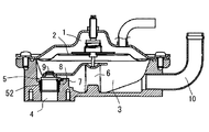
そして、前記レギュレータによるガス燃料の調圧制御は、例えば特開2003−232265号公報などに提示されており、図6に示すように、大気側に連通した背圧室1側とダイヤフラム2で区画された調圧室3への燃料導入口4に弁5を設置し、背圧室1側の大気圧に対応して設置された制御圧セットバネ6で荷重されたダイヤフラム2の往復変位動作をピン7により回動可能に支持された弁レバー8で伝達して弁5を開閉させることにより行っている。
The regulation control of gas fuel by the regulator is disclosed in, for example, Japanese Patent Laid-Open No. 2003-232265, and as shown in FIG. The
ところで、このガス燃料供給用のレギュレータの弁5は、図7および図8に示すように、燃料導入口4の出口に設置された全体が筒状で頂部の開口縁を弁シート51とする弁座52と、前記弁シート51に密に接する円板状の当り面53を有する弁体54により構成され、製品の組立ごとにリーク量を管理した後、弁体54を前記弁座52側にピン7により回動可能に支持された弁レバー8に保持部材9を介して接着剤82により接着することにより支持するものである。
By the way, as shown in FIG. 7 and FIG. 8, the
そのため、組み付け後の再組み付けや弁体54などの交換を行うと予め調整してあった弁体54と弁座52との相対関係が失われてしまい規定のシール性能が確保できなくなるという問題がある。
Therefore, there is a problem that the relative relationship between the
そこで、従来、例えば図8に示すように、前記弁体54への接触する底部を半円球とした保持部材9を使用して弁体54を保持部材9に対して自由接続(弁体54の中心において全周囲方向に傾動可能に取り付ける)として前記弁レバー8による弁体54の動きに応じて弁座52との相対的な傾きを自動補正させる弁5が提示されている。
Therefore, conventionally, for example, as shown in FIG. 8, the
しかしながら、前記自動調整式の弁5は、微少流量域、即ち、弁体54の開度が少ない状態において、弁体54の着座性の不安定が微少圧力の制御性を悪化させ、また、弁体54がフリー状態にあることから弁体54が不安定となり信頼性に欠けるなどの問題がある。
However, in the case of the self-adjusting
本発明は、前記従来のガス燃料供給用のレギュレータの弁が有する問題点を解決して、弁体と弁座との相対位置関係を自動補正可能にするとともに弁体が常時安定した弁座への着座性を発揮することができるガス燃料供給用のレギュレータを提供することを課題とする。 The present invention solves the problems of the valve of the above-mentioned conventional regulator for gas fuel supply and enables automatic correction of the relative positional relationship between the valve body and the valve seat and the valve seat is always stable. It is an object of the present invention to provide a regulator for gas fuel supply which can exhibit the seating performance of the vehicle.
前記課題を解決するためになされた本発明は、大気側に連通した背圧室側とダイヤフラムで区画された調圧室への燃料導入口に配置された円形筒状の弁座に当接する円形の弁体を保持する保持部材をピンにより回動可能に支持された弁レバーに連結し、前記背圧室側の大気圧に対応して設置された制御圧セットバネで荷重された前記ダイヤフラムの往復変位動作により生じる前記弁レバーの揺動により開閉する弁を有するガス燃料供給用のレギュレータにおいて、前記弁体を保持する保持部材が、前記弁体の頂面に接する底部を半円球にするとともに中心に前記弁体に形成した通孔に連通するとともに軸線方向の所定の位置に固定凹部を形成した保持部材本体と、全体が弾性材により形成された所定径を有する軸状で基端に係止部を突設させるとともに軸部の軸線方向所定位置に前記保持部材本体に形成した通孔に形成した固定凹部に嵌合する固定凸部を膨出した固着部材とからなり、前記互いに重ねた弁体と保持部材本体の中心において連通する通孔に前記固着部材を弁体の底面側から前記固定凸部が前記固定凹部に嵌合するまで差し込み、前記固着部材の前記係止部と前記固定凸部により前記弁体を保持部材に保持させていることを特徴とする。 The present invention, which has been made to solve the above problems, has a circular shape in contact with a circular cylindrical valve seat disposed at a back pressure chamber side communicating with the atmosphere side and a fuel inlet port to a pressure regulating chamber partitioned by a diaphragm. The holding member holding the valve body of the valve is connected to a valve lever rotatably supported by a pin, and reciprocation of the diaphragm loaded by a control pressure set spring installed corresponding to the atmospheric pressure on the back pressure chamber side In a regulator for gas fuel supply having a valve which is opened and closed by swinging of the valve lever generated by a displacement operation, a holding member for holding the valve body makes a bottom portion contacting the top surface of the valve body a semicircular ball. A holding member main body which communicates with the through hole formed in the valve body at the center and has a fixed recess formed at a predetermined position in the axial direction, and an axial shape having a predetermined diameter entirely formed of an elastic material. Make stop part project And a fixing member in which a fixing convex portion fitted in a fixing recess formed in the through hole formed in the holding member main body at a predetermined position in the axial direction of the shaft portion is expanded, and the valve body and the holding member main body overlapped with each other The fixed member is inserted into the through hole communicating at the center of the valve from the bottom side of the valve until the fixed protrusion fits into the fixed recess, and the locking member of the fixed member and the fixed protrusion form the valve Is held by the holding member.
本発明によると、保持部材は前記図9に示した従来例のように、前記保持部材本体の弁体への接触する底部を半円球としたことから弁体を保持部材に対して自由接続(弁体の中心において前周囲方向に傾動可能に取り付ける)として前記弁レバーによる弁体の動きに応じて弁座との相対的な傾きを自動補正させることができることはいうまでもなく、保持部材と弁体とが弾性を有する軸部材により互いに連結保持されているので弁座の弁シートに対して弁レバーが傾いた場合にも弁体は弾性を有する固着部材が軸線を曲げて保持部材の底部である球面に沿って稼働することで弁座の弁シートに着座した状態を保つことになる。 According to the present invention, as in the conventional example shown in FIG. 9, the holding member is a semi-spherical bottom portion of the holding member main body in contact with the valve body, so that the valve body can be freely connected to the holding member. It goes without saying that relative inclination with the valve seat can be automatically corrected according to the movement of the valve body by the valve lever as (pivotably mounted in the center of the valve body in the forward circumferential direction). Since the valve body and the valve body are mutually connected and held by the elastic shaft member, even when the valve lever is inclined with respect to the valve seat of the valve seat, the fixing member having the elastic body bends the axis and the holding member By operating along the spherical surface which is the bottom part, it will stay seated on the valve seat of the valve seat.
そのため、弁の開度が少ない状態において、弁体の着座性の不安定が微少圧力の制御性を悪化させ、また、弁体がフリー状態にあることから弁体が不安定となり信頼性に欠けるなどの従来の問題点が解消される。 Therefore, in the state where the opening degree of the valve is small, the instability of the seating property of the valve body deteriorates the controllability of the minute pressure, and the valve body becomes unstable due to the free state and the reliability is poor. And other conventional problems are eliminated.
更に、本発明において、前記固着部材の前記係止部の頂面に前記弁体の底面における前記弁座の弁シートへの着座面を覆う弾性材からなる膜体を一体的に拡設させた場合には、シール性の向上を図った弁体を安価に提供することができる。 Furthermore, in the present invention, a membrane body made of an elastic material covering the seating surface of the valve seat on the valve seat on the bottom surface of the valve body is integrally expanded on the top surface of the locking portion of the fixing member. In such a case, it is possible to inexpensively provide a valve body in which sealing performance is improved.
本発明によれば、組み付け後の再組み付けや弁体などの交換を行っても調整してある弁体と弁座との相対関係を失うことがなく、規定のシール性能を確保することができるばかりか、常に、弁体の着座性が安定しており、信頼性に優れた弁を有するガス燃料供給用のレギュレータを提供することができるものである。 According to the present invention, it is possible to ensure a prescribed sealing performance without losing the relative relationship between the adjusted valve body and the valve seat even after reassembling after assembly or replacing the valve body etc. Besides, it is always possible to provide a regulator for gas fuel supply which has a stable seating property of the valve body and has a highly reliable valve.
以下に、本発明の好ましい実施の形態について図面を参照して詳細に説明する。 Hereinafter, preferred embodiments of the present invention will be described in detail with reference to the drawings.
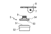
図1乃至図4は本発明である燃料供給装置の好ましい実施の形態を示すものであり、全体の構成は前記図6に示した従来例とほぼ同様で図1に示すように、大気側に連通した背圧室1側とダイヤフラム2で区画された調圧室3への燃料導入口4に弁5を設置し、背圧室1側の大気圧に対応して設置された制御圧セットバネ6で荷重されたダイヤフラム2の往復変位動作をピン7により回動可能に支持された弁レバー8で伝達して保持部材9を介して弁5を開閉させることにより前記弁5が配置される燃料導入口4から導入したLPG(液化石油ガス)、CNG(圧縮天然ガス)などのガス燃料を調圧室3で大気圧程度に減圧調整し、エンジンに供給する際に燃料出口10から排出してミキサまたはインジェクタに送り、吸気管路からガスエンジンに供給するものである。
1 to 4 show a preferred embodiment of the fuel supply system according to the present invention, and the whole construction is substantially the same as that of the prior art shown in FIG. 6, and as shown in FIG. A control pressure set
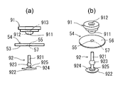
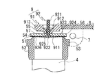
本実施の形態において最も特徴的である弁5は、図2および図3に示すように、燃料導入口4の出口に設置される全体が筒状で頂部の開口縁を弁シート51とする弁座52と、前記弁シート51に密に接する円板状の当り面53を有する弁体54を有し、特に、弁体54の中心には所定径を有する通孔55が貫通、形成されている。
The
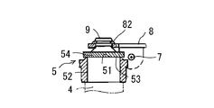
また、前記弁体54を前記ダイヤフラム2の往復変位動作をピン7により回動可能に支持された弁レバー8に接続するための弁体54の保持部材9が、前記弁体54の頂面56に接して配置されるとともに前記弁レバー8に連結される保持部材本体91と、前記弁体54と保持部材本体91とを固着する固着部材92とから構成される。
Further, the
前記保持部材本体91は、底部911を半円球にするとともに中心に前記弁体54に形成した通孔55に連通する通孔912が形成されているとともに通孔912における軸線方向の所定の位置に固定凹部913が形成されている。
The holding member
一方、保持部材本体91と弁体54とを固着する固着部材92は、全体が例えば適宜硬質のNBR(ニトリルブタジエンゴム)のような耐油性、耐摩耗性、耐老化性、耐引裂性などに優れたゴム材のような弾性材により形成された所定径を有する軸状で軸部921の基端に皿状の係止部922を突設させるとともに軸部921の軸線方向所定位置に前記保持部材本体91の通孔912に形成した固定凹部913に嵌合する固定凸部923が膨出されている。
On the other hand, the
そして、互いに重ねた弁体54と保持部材本体91の中心において互いに連通する通孔55,912に固着部材92を弁体54の底面(当り面53)側から差し込み固定凸部923を固定凹部913に嵌合させ、弁体54を保持部材9に保持させる。
Then, the
本発明によると、保持部材は前記図9に示した従来例のように、保持部材本体91の弁体54へ接触する底部911を半円球としたことから弁体54を保持部材9に対して自由接続(弁体54の中心において全周囲方向に傾動可能に取り付ける)として連結した弁レバー8による弁体54の動きに応じて弁座52との相対的な傾きを自動補正させることができることはいうまでもなく、保持部材本体91と弁体54とが弾性を有する固着部材92により互いに連結保持されている。
According to the present invention, as in the conventional example shown in FIG. 9, since the
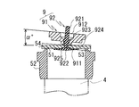
従って、図4に示すように、弁座52の弁シート51に対して弁レバー8が傾いた場合にも弁体54は弾性を有する固着部材92が軸線を曲げて保持部材本体91の底部911である球面に沿って稼働することで弁座52の弁シート51に着座した状態を保つことになる。
Therefore, as shown in FIG. 4, even when the
そのため、弁5の開度が少ない状態において、弁体54の着座性の不安定が微少圧力の制御性を悪化させ、また、弁体54がフリー状態にあることから生じる弁体54が不安定となり信頼性に欠けるなどの従来の問題点が解消される。
Therefore, in the state where the opening degree of the
更に、本実施の形態では、固着部材92の係止部922の頂面924における軸部921の周囲に円柱状の拡張部925が形成されているとともに弁体54の当り面53に前記拡張部925が嵌挿される嵌挿凹部57が形成されており、両者が嵌合することで弁体54と固着部材92とがより一体的に固着されるようになっている。
Furthermore, in the present embodiment, a cylindrical expanded
尚、本実施の形態において、前記保持部材本体91と弁体54とを固着する固着部材92の硬度は、弁体54が弁座52に着座するときの弁体54と弁座52との傾き度(図示するα°)を生じた際に前記弁レバー8を付勢する制御圧セットバネ6の押し付け力によって完全着座するように屈曲可能且つ弁体54を弁座52に密着させることが可能な硬さと柔軟性が発揮可能な範囲に設定され、制御圧セットバネ6の荷重、固着部材92の軸径、弁体54の位置や弁レバー8の形状や取り付け位置などを考慮して設定される。
In the present embodiment, the hardness of the
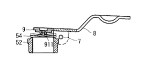
また、図5は本発明の異なる実施の形態を示すものであり、全体の構造及び作用・効果は前記図1乃至図4に示した実施の形態とほぼ同様であるが、固着部材92の係止部922の頂面924に弁体54の底面における弁座の弁シート51を覆う弾性材からなる膜体926が一体的に拡設されている。
FIG. 5 shows another embodiment of the present invention, and the overall structure, operation and effects are substantially the same as those of the embodiment shown in FIGS. A
本実施の形態では、シール性の向上を図った弁体を安価に提供することができる。 In the present embodiment, it is possible to inexpensively provide a valve body in which sealing performance is improved.
1 背圧室、2 ダイヤフラム、3 調圧室、4 燃料導入口、5 弁、6 制御圧セットバネ、7 ピン、8 弁レバー、9 保持部材、10 燃料出口、51 弁シート、52 弁座、53 当り面、54 弁体、55 通孔、56 頂面、57 嵌挿凹部、91 保持部材本体、92 固着部材、911 底部、912 通孔、913 固定凹部、921 軸部、922 係止部、923 固定凸部、924 頂面、925 拡張部
DESCRIPTION OF SYMBOLS 1
Claims (3)
Priority Applications (2)
| Application Number | Priority Date | Filing Date | Title |
|---|---|---|---|
| JP2015140664A JP6527770B2 (en) | 2015-07-14 | 2015-07-14 | Regulator for gas fuel supply |
| US15/209,736 US10120395B2 (en) | 2015-07-14 | 2016-07-13 | Gas-fuel-supply regulator |
Applications Claiming Priority (1)
| Application Number | Priority Date | Filing Date | Title |
|---|---|---|---|
| JP2015140664A JP6527770B2 (en) | 2015-07-14 | 2015-07-14 | Regulator for gas fuel supply |
Publications (2)
| Publication Number | Publication Date |
|---|---|
| JP2017020456A JP2017020456A (en) | 2017-01-26 |
| JP6527770B2 true JP6527770B2 (en) | 2019-06-05 |
Family
ID=57775781
Family Applications (1)
| Application Number | Title | Priority Date | Filing Date |
|---|---|---|---|
| JP2015140664A Active JP6527770B2 (en) | 2015-07-14 | 2015-07-14 | Regulator for gas fuel supply |
Country Status (2)
| Country | Link |
|---|---|
| US (1) | US10120395B2 (en) |
| JP (1) | JP6527770B2 (en) |
Families Citing this family (4)
| Publication number | Priority date | Publication date | Assignee | Title |
|---|---|---|---|---|
| KR102331425B1 (en) | 2016-05-25 | 2021-11-25 | 스웨이지락 캄파니 | Valves with self-aligning stem tips |
| EP3418635B1 (en) * | 2017-06-20 | 2021-05-19 | Honeywell Technologies Sarl | Gas valve and gas control device |
| US11047501B2 (en) * | 2017-07-14 | 2021-06-29 | Robertshaw Controls Company | Normally open gas valve |
| US11873915B1 (en) * | 2021-12-30 | 2024-01-16 | United States Of America As Represented By The Administrator Of Nasa | Poppet valve with pivotable seal |
Family Cites Families (11)
| Publication number | Priority date | Publication date | Assignee | Title |
|---|---|---|---|---|
| US1293227A (en) * | 1916-05-27 | 1919-02-04 | Arthur L Smyly | Fluid-pressure governor. |
| US1618396A (en) * | 1924-04-08 | 1927-02-22 | Adolph Mueller | Gas-pressure regulator |
| US1950120A (en) * | 1931-05-23 | 1934-03-06 | Garnet W Mckee | Regulator |
| US2215419A (en) * | 1936-03-20 | 1940-09-17 | Sprague Meter Company | Gas regulator |
| US2263581A (en) * | 1940-01-22 | 1941-11-25 | Reynolds Gas Regulator Company | Gas regulator |
| US3339581A (en) * | 1965-06-15 | 1967-09-05 | Textron Inc | Fluid pressure regulator valve |
| JPS533448B2 (en) * | 1974-01-12 | 1978-02-07 | ||
| DE19509943A1 (en) * | 1995-03-18 | 1996-09-19 | Stihl Maschf Andreas | Diaphragm carburettor for IC engine |
| JP2003232265A (en) | 2002-02-12 | 2003-08-22 | Nikki Co Ltd | Gas fuel supply regulator |
| US7219689B2 (en) * | 2004-11-09 | 2007-05-22 | The Gsi Group, Inc. | Automatically flushing water regulator for animal watering systems |
| US8695629B2 (en) * | 2011-12-09 | 2014-04-15 | Cheng-Sheng Hsiao | Manually operable gas regulator |
-
2015
- 2015-07-14 JP JP2015140664A patent/JP6527770B2/en active Active
-
2016
- 2016-07-13 US US15/209,736 patent/US10120395B2/en not_active Expired - Fee Related
Also Published As
| Publication number | Publication date |
|---|---|
| JP2017020456A (en) | 2017-01-26 |
| US10120395B2 (en) | 2018-11-06 |
| US20170017244A1 (en) | 2017-01-19 |
Similar Documents
| Publication | Publication Date | Title |
|---|---|---|
| JP6527770B2 (en) | Regulator for gas fuel supply | |
| CN102042126B (en) | Gas fuel supply apparatus | |
| KR101238566B1 (en) | Gas fuel supply apparatus | |
| CN111561592A (en) | Regulator | |
| CA2953094C (en) | Structure and method for fastening ball seat for ball valve, trunnion-type ball valve, and hydrogen station using said valve | |
| KR102024517B1 (en) | trunnion ball valve | |
| JP2021025540A (en) | Ball valve | |
| US10216202B2 (en) | Pressure regulating valve | |
| JP2019015181A (en) | Regulator for gas fuel supply | |
| US10817002B2 (en) | Gas valve and gas control device | |
| JP2018156259A (en) | Pressure regulating valve | |
| US20190145352A1 (en) | Fuel supply device with inlet valve | |
| EP1967727A3 (en) | Fuel injector with improved implementation of a control valve for controlling an injection needle | |
| JP2015210746A (en) | Pressure reduction valve | |
| KR200449630Y1 (en) | Automotive shut-off device for valve assembly of LP containers | |
| JP4989676B2 (en) | Pressure regulating valve | |
| JP3254764U (en) | pressure regulator | |
| JP7053280B2 (en) | Valve device | |
| JP7112282B2 (en) | fluid control valve | |
| JP2021014847A (en) | Pressure control unit and fuel supply system | |
| JP4393369B2 (en) | Pressure regulator | |
| JP2017157119A (en) | Pressure regulating valve | |
| KR101414534B1 (en) | Vaporizer | |
| JP2014229265A (en) | Pressure adjustment valve | |
| JP6494456B2 (en) | Governor |
Legal Events
| Date | Code | Title | Description |
|---|---|---|---|
| A621 | Written request for application examination |
Free format text: JAPANESE INTERMEDIATE CODE: A621 Effective date: 20180703 |
|
| A977 | Report on retrieval |
Free format text: JAPANESE INTERMEDIATE CODE: A971007 Effective date: 20190411 |
|
| TRDD | Decision of grant or rejection written | ||
| A01 | Written decision to grant a patent or to grant a registration (utility model) |
Free format text: JAPANESE INTERMEDIATE CODE: A01 Effective date: 20190417 |
|
| A61 | First payment of annual fees (during grant procedure) |
Free format text: JAPANESE INTERMEDIATE CODE: A61 Effective date: 20190513 |
|
| R150 | Certificate of patent or registration of utility model |
Ref document number: 6527770 Country of ref document: JP Free format text: JAPANESE INTERMEDIATE CODE: R150 |
|
| R250 | Receipt of annual fees |
Free format text: JAPANESE INTERMEDIATE CODE: R250 |
|
| R250 | Receipt of annual fees |
Free format text: JAPANESE INTERMEDIATE CODE: R250 |
|
| R250 | Receipt of annual fees |
Free format text: JAPANESE INTERMEDIATE CODE: R250 |
|
| R250 | Receipt of annual fees |
Free format text: JAPANESE INTERMEDIATE CODE: R250 |
|
| R250 | Receipt of annual fees |
Free format text: JAPANESE INTERMEDIATE CODE: R250 |