JP6526185B2 - Loudspeaker with reduced audio coloration caused by surface reflections - Google Patents
Loudspeaker with reduced audio coloration caused by surface reflections Download PDFInfo
- Publication number
- JP6526185B2 JP6526185B2 JP2017517245A JP2017517245A JP6526185B2 JP 6526185 B2 JP6526185 B2 JP 6526185B2 JP 2017517245 A JP2017517245 A JP 2017517245A JP 2017517245 A JP2017517245 A JP 2017517245A JP 6526185 B2 JP6526185 B2 JP 6526185B2
- Authority
- JP
- Japan
- Prior art keywords
- cabinet
- transducer
- sound
- transducers
- loudspeaker
- Prior art date
- Legal status (The legal status is an assumption and is not a legal conclusion. Google has not performed a legal analysis and makes no representation as to the accuracy of the status listed.)
- Active
Links
- 230000002829 reductive effect Effects 0.000 title description 18
- 238000001914 filtration Methods 0.000 claims description 30
- 230000001154 acute effect Effects 0.000 claims description 8
- 238000005304 joining Methods 0.000 claims description 3
- 230000000087 stabilizing effect Effects 0.000 claims 1
- 230000000694 effects Effects 0.000 description 22
- 230000005236 sound signal Effects 0.000 description 9
- 238000005192 partition Methods 0.000 description 7
- 230000004044 response Effects 0.000 description 7
- 238000013459 approach Methods 0.000 description 5
- 238000010586 diagram Methods 0.000 description 5
- 239000000463 material Substances 0.000 description 5
- 230000001413 cellular effect Effects 0.000 description 4
- 230000006870 function Effects 0.000 description 4
- 230000000670 limiting effect Effects 0.000 description 4
- 238000000034 method Methods 0.000 description 4
- 230000002745 absorbent Effects 0.000 description 3
- 239000002250 absorbent Substances 0.000 description 3
- 239000002184 metal Substances 0.000 description 3
- 229910001092 metal group alloy Inorganic materials 0.000 description 3
- 230000009467 reduction Effects 0.000 description 3
- 101710097688 Probable sphingosine-1-phosphate lyase Proteins 0.000 description 2
- 101710105985 Sphingosine-1-phosphate lyase Proteins 0.000 description 2
- 101710122496 Sphingosine-1-phosphate lyase 1 Proteins 0.000 description 2
- 230000008901 benefit Effects 0.000 description 2
- 230000003111 delayed effect Effects 0.000 description 2
- 230000007774 longterm Effects 0.000 description 2
- 238000010295 mobile communication Methods 0.000 description 2
- 239000007787 solid Substances 0.000 description 2
- 239000011358 absorbing material Substances 0.000 description 1
- 238000003491 array Methods 0.000 description 1
- 230000002238 attenuated effect Effects 0.000 description 1
- 230000006399 behavior Effects 0.000 description 1
- 238000013500 data storage Methods 0.000 description 1
- 230000007423 decrease Effects 0.000 description 1
- 230000003247 decreasing effect Effects 0.000 description 1
- 230000001934 delay Effects 0.000 description 1
- 230000001066 destructive effect Effects 0.000 description 1
- 238000009792 diffusion process Methods 0.000 description 1
- 239000006260 foam Substances 0.000 description 1
- 238000004519 manufacturing process Methods 0.000 description 1
- 238000004377 microelectronic Methods 0.000 description 1
- 238000012986 modification Methods 0.000 description 1
- 230000004048 modification Effects 0.000 description 1
- 229920000642 polymer Polymers 0.000 description 1
- 230000008569 process Effects 0.000 description 1
- 238000012545 processing Methods 0.000 description 1
- 230000005855 radiation Effects 0.000 description 1
- 230000002441 reversible effect Effects 0.000 description 1
- 238000000263 scanning probe lithography Methods 0.000 description 1
- 230000013707 sensory perception of sound Effects 0.000 description 1
- 239000000725 suspension Substances 0.000 description 1
Images


Classifications
-
- H—ELECTRICITY
- H04—ELECTRIC COMMUNICATION TECHNIQUE
- H04R—LOUDSPEAKERS, MICROPHONES, GRAMOPHONE PICK-UPS OR LIKE ACOUSTIC ELECTROMECHANICAL TRANSDUCERS; DEAF-AID SETS; PUBLIC ADDRESS SYSTEMS
- H04R1/00—Details of transducers, loudspeakers or microphones
- H04R1/20—Arrangements for obtaining desired frequency or directional characteristics
- H04R1/22—Arrangements for obtaining desired frequency or directional characteristics for obtaining desired frequency characteristic only
- H04R1/28—Transducer mountings or enclosures modified by provision of mechanical or acoustic impedances, e.g. resonator, damping means
- H04R1/2807—Enclosures comprising vibrating or resonating arrangements
- H04R1/2811—Enclosures comprising vibrating or resonating arrangements for loudspeaker transducers
-
- H—ELECTRICITY
- H04—ELECTRIC COMMUNICATION TECHNIQUE
- H04R—LOUDSPEAKERS, MICROPHONES, GRAMOPHONE PICK-UPS OR LIKE ACOUSTIC ELECTROMECHANICAL TRANSDUCERS; DEAF-AID SETS; PUBLIC ADDRESS SYSTEMS
- H04R1/00—Details of transducers, loudspeakers or microphones
- H04R1/02—Casings; Cabinets ; Supports therefor; Mountings therein
- H04R1/025—Arrangements for fixing loudspeaker transducers, e.g. in a box, furniture
-
- H—ELECTRICITY
- H04—ELECTRIC COMMUNICATION TECHNIQUE
- H04R—LOUDSPEAKERS, MICROPHONES, GRAMOPHONE PICK-UPS OR LIKE ACOUSTIC ELECTROMECHANICAL TRANSDUCERS; DEAF-AID SETS; PUBLIC ADDRESS SYSTEMS
- H04R1/00—Details of transducers, loudspeakers or microphones
- H04R1/20—Arrangements for obtaining desired frequency or directional characteristics
- H04R1/22—Arrangements for obtaining desired frequency or directional characteristics for obtaining desired frequency characteristic only
- H04R1/26—Spatial arrangements of separate transducers responsive to two or more frequency ranges
-
- H—ELECTRICITY
- H04—ELECTRIC COMMUNICATION TECHNIQUE
- H04R—LOUDSPEAKERS, MICROPHONES, GRAMOPHONE PICK-UPS OR LIKE ACOUSTIC ELECTROMECHANICAL TRANSDUCERS; DEAF-AID SETS; PUBLIC ADDRESS SYSTEMS
- H04R1/00—Details of transducers, loudspeakers or microphones
- H04R1/20—Arrangements for obtaining desired frequency or directional characteristics
- H04R1/22—Arrangements for obtaining desired frequency or directional characteristics for obtaining desired frequency characteristic only
- H04R1/28—Transducer mountings or enclosures modified by provision of mechanical or acoustic impedances, e.g. resonator, damping means
- H04R1/2803—Transducer mountings or enclosures modified by provision of mechanical or acoustic impedances, e.g. resonator, damping means for loudspeaker transducers
-
- H—ELECTRICITY
- H04—ELECTRIC COMMUNICATION TECHNIQUE
- H04R—LOUDSPEAKERS, MICROPHONES, GRAMOPHONE PICK-UPS OR LIKE ACOUSTIC ELECTROMECHANICAL TRANSDUCERS; DEAF-AID SETS; PUBLIC ADDRESS SYSTEMS
- H04R1/00—Details of transducers, loudspeakers or microphones
- H04R1/20—Arrangements for obtaining desired frequency or directional characteristics
- H04R1/22—Arrangements for obtaining desired frequency or directional characteristics for obtaining desired frequency characteristic only
- H04R1/28—Transducer mountings or enclosures modified by provision of mechanical or acoustic impedances, e.g. resonator, damping means
- H04R1/2869—Reduction of undesired resonances, i.e. standing waves within enclosure, or of undesired vibrations, i.e. of the enclosure itself
- H04R1/2876—Reduction of undesired resonances, i.e. standing waves within enclosure, or of undesired vibrations, i.e. of the enclosure itself by means of damping material, e.g. as cladding
- H04R1/288—Reduction of undesired resonances, i.e. standing waves within enclosure, or of undesired vibrations, i.e. of the enclosure itself by means of damping material, e.g. as cladding for loudspeaker transducers
-
- H—ELECTRICITY
- H04—ELECTRIC COMMUNICATION TECHNIQUE
- H04R—LOUDSPEAKERS, MICROPHONES, GRAMOPHONE PICK-UPS OR LIKE ACOUSTIC ELECTROMECHANICAL TRANSDUCERS; DEAF-AID SETS; PUBLIC ADDRESS SYSTEMS
- H04R1/00—Details of transducers, loudspeakers or microphones
- H04R1/20—Arrangements for obtaining desired frequency or directional characteristics
- H04R1/32—Arrangements for obtaining desired frequency or directional characteristics for obtaining desired directional characteristic only
- H04R1/40—Arrangements for obtaining desired frequency or directional characteristics for obtaining desired directional characteristic only by combining a number of identical transducers
- H04R1/403—Arrangements for obtaining desired frequency or directional characteristics for obtaining desired directional characteristic only by combining a number of identical transducers loud-speakers
-
- H—ELECTRICITY
- H04—ELECTRIC COMMUNICATION TECHNIQUE
- H04R—LOUDSPEAKERS, MICROPHONES, GRAMOPHONE PICK-UPS OR LIKE ACOUSTIC ELECTROMECHANICAL TRANSDUCERS; DEAF-AID SETS; PUBLIC ADDRESS SYSTEMS
- H04R3/00—Circuits for transducers, loudspeakers or microphones
- H04R3/12—Circuits for transducers, loudspeakers or microphones for distributing signals to two or more loudspeakers
- H04R3/14—Cross-over networks
-
- H—ELECTRICITY
- H04—ELECTRIC COMMUNICATION TECHNIQUE
- H04R—LOUDSPEAKERS, MICROPHONES, GRAMOPHONE PICK-UPS OR LIKE ACOUSTIC ELECTROMECHANICAL TRANSDUCERS; DEAF-AID SETS; PUBLIC ADDRESS SYSTEMS
- H04R2201/00—Details of transducers, loudspeakers or microphones covered by H04R1/00 but not provided for in any of its subgroups
- H04R2201/40—Details of arrangements for obtaining desired directional characteristic by combining a number of identical transducers covered by H04R1/40 but not provided for in any of its subgroups
- H04R2201/401—2D or 3D arrays of transducers
Description
本出願は、2014年9月30日出願の米国特許仮出願第62/057,992号の利益を主張し、本出願はこの仮特許出願を参照により本明細書に組み込む。 This application claims the benefit of US Provisional Patent Application No. 62 / 057,992, filed on September 30, 2014, which is incorporated herein by reference.
ラウドスピーカが置かれている表面からの反射によって引き起こされる効果を低減するラウドスピーカが開示される。一実施形態では、ラウドスピーカは、反射面、例えば、テーブル面又は床面に置かれるベースプレートから特定距離内に位置する個々のトランスデューサを有し、それによって、トランスデューサからの反射音及び直接音の進行距離は、ほぼ同等になる。他の実施形態もまた記載されている。 A loudspeaker is disclosed that reduces the effects caused by reflections from the surface on which the loudspeaker is placed. In one embodiment, the loudspeaker comprises individual transducers located within a specific distance from a reflective surface, for example a base plate placed on a table or floor surface, whereby the progression of reflected and direct sound from the transducers The distances will be approximately equal. Other embodiments are also described.
ラウドスピーカは、音を聴取エリア内に出力するためにコンピュータ及び家電によって使用される場合がある。ラウドスピーカは、スピーカキャビネット内に配置された複数の電気音響トランスデューサから構成され得る。スピーカキャビネットは、テーブル面などの硬い反射面に設置され得る。トランスデューサがテーブル面に近接している場合、テーブル面からの反射により、聴取者に対して望ましくないコムフィルタリング効果が引き起こされる場合がある。反射経路は音の直接経路より長いので、反射音は、直接音より遅く到達する場合がある。反射音は、(遅延によって引き起こされる)2つの音の間の位相差に基づいて(聴取者の耳で)直接音と強め合う干渉又は弱め合う干渉を引き起こす場合がある。 Loudspeakers may be used by computers and appliances to output sound into the listening area. The loudspeaker may consist of a plurality of electroacoustic transducers arranged in a loudspeaker cabinet. The speaker cabinet may be installed on a hard reflective surface such as a table surface. If the transducer is close to the table surface, reflections from the table surface may cause undesirable comb filtering effects for the listener. Because the reflection path is longer than the direct path of sound, the reflected sound may arrive later than the direct sound. The reflected sound may cause constructive or destructive interference with the direct sound (at the listener's ear) based on the phase difference between the two sounds (caused by the delay).
この背景の部分で説明する取り組み方は、遂行可能な取り組み方ではあるが、必ずしも以前に考案され又は遂行されたことのある取り組み方とは限らない。したがって、特に断りのない限り、本節で説明する取り組み方のいずれも、ただ単に本節に含まれているからというだけで、先行技術であるとみなすべきではない。 The approaches described in this background section are approaches that can be performed, but not necessarily approaches that have been previously conceived or accomplished. Thus, unless specifically stated otherwise, none of the approaches described in this section should be regarded as prior art merely because it is included in this section.
一実施形態では、ラウドスピーカは、キャビネット内の平面内に整列されたトランスデューサの環を備えている。一実施形態では、ラウドスピーカは、トランスデューサがすべて複製であり、それぞれが同じ周波数範囲内の音を生成するアレイであるように設計されてもよい。他の実施形態では、ラウドスピーカは、すべてのトランスデューサが同じ周波数範囲内で作動するように設計されているわけではないマルチウェイスピーカであってもよい。ラウドスピーカは、キャビネットの下端と連結されたベースプレートを含んでもよい。ベースプレートは、テーブル面、又は別の表面(例えば、床)の上に着座している間に、キャビネットが簡単に転倒しないように、ラウドスピーカに安定性を付与する大きさの固体平坦構造体とすることができる。トランスデューサの環は、キャビネットの底部でベースプレートから所定距離内に位置してもよいし、(ベースプレートが使用されず、キャビネットの下端がテーブル面又は床の上に置かれる場合には)テーブル面又は床から所定距離内に位置してもよい。トランスデューサは、直立しているトランスデューサと比較して、トランスデューサからの音のテーブル面又は床から反射によって引き起こされるコムフィルタリングを低減するように、下端に向かって下向きに所定鋭角で傾けてもよい。 In one embodiment, the loudspeaker comprises an annulus of transducers aligned in a plane in the cabinet. In one embodiment, the loudspeakers may be designed such that the transducers are all duplicates, each being an array producing sound in the same frequency range. In other embodiments, the loudspeakers may be multi-way speakers, not all transducers are designed to operate within the same frequency range. The loudspeaker may include a base plate coupled to the lower end of the cabinet. The base plate is a solid flat structure sized to provide stability to the loudspeaker so that the cabinet does not easily tip over while seated on a table surface or another surface (e.g. floor) can do. The transducer ring may be located within a predetermined distance from the base plate at the bottom of the cabinet or (if the base plate is not used and the lower end of the cabinet is placed on a table surface or floor) a table surface or floor It may be located within a predetermined distance from The transducer may be inclined downward towards the lower end at a predetermined acute angle so as to reduce comb filtering caused by reflections from the table surface or floor of the sound from the transducer as compared to an upright transducer.
トランスデューサによって放出される音は、トランスデューサからの直接音とともに聴取者の耳に到達する前に、キャビネットが置かれているベースプレート又は他の反射面から反射される場合がある。所定距離は、反射音経路及び直接音経路が同様となることを確実にするように選択され得、それによって聴取者が知覚できるコムフィルタリング効果が低減される。一部の実施形態では、所定距離は、対応するトランスデューサの大きさ若しくは寸法に基づいて、又はトランスデューサによって放出されるオーディオ周波数の組に基づいて選択され得る。 The sound emitted by the transducer may be reflected from a base plate or other reflective surface on which the cabinet is placed, before reaching the listener's ear with the direct sound from the transducer. The predetermined distance may be selected to ensure that the reflected sound path and the direct sound path are similar, thereby reducing the comb filtering effect that the listener can perceive. In some embodiments, the predetermined distance may be selected based on the size or dimensions of the corresponding transducer or based on the set of audio frequencies emitted by the transducer.
一実施形態では、この所定距離は、トランスデューサをキャビネットの下端に向かって下向きに傾けることによって達成され得る。この回転又は傾斜は、所定距離が望ましくない共鳴を引き起こさずに達成されるような値の範囲内とすることができる。一実施形態では、トランスデューサを、鋭角に、例えば、キャビネットの下端に対して(あるいは、ベースプレートが使用される場合は、ベースプレートに対して)37.5°〜42.5°に回転又は傾斜した。 In one embodiment, this predetermined distance may be achieved by tilting the transducer downward toward the lower end of the cabinet. This rotation or tilting can be in the range of values such that the predetermined distance is achieved without causing unwanted resonances. In one embodiment, the transducer was rotated or tilted at an acute angle, for example 37.5 ° to 42.5 ° with respect to the lower end of the cabinet (or alternatively, if a base plate is used, relative to the base plate).
別の実施形態では、所定距離は、ホーンを使用することによって達成することができる。ホーンは、トランスデューサからの音を、下端に近接して位置するキャビネット内の音出力開口部に向けることができる。したがって、開口部の中心が、音が聴取エリア内に伝播できる地点であるので、この場合の所定距離は、開口部の中心と、テーブル面、床又はベースプレートとの間とすることができる。ホーンの使用によって、所定距離は、トランスデューサ自体を下端又はベースプレートに近接するよう移動又は配置する必要はなく、短くすることができる。 In another embodiment, the predetermined distance can be achieved by using a horn. The horn can direct the sound from the transducer to a sound output opening in the cabinet located close to the lower end. Thus, since the center of the opening is the point at which sound can propagate into the listening area, the predetermined distance in this case can be between the center of the opening and the table surface, floor or base plate. By use of the horn, the predetermined distance can be shortened without having to move or position the transducer itself close to the lower end or the base plate.
上述したように、本明細書に記載するラウドスピーカは、従来のラウドスピーカより改善された性能を示すことができる。特に、本明細書に記載するラウドスピーカは、1)トランスデューサの垂直(高さ)又は回転調整によってトランスデューサを、ラウドスピーカが置かれ得る反射面(例えば、ベースプレート又は直接、テーブル面若しくは床の上)の近くに移動すること、あるいは、2)ホーン及び反射面から所定距離にあるキャビネット内の開口部を使用することにより、音が反射面に近接する聴取エリア内に解放されるように、トランスデューサによって生成された音を案内することによって、聴取者が知覚するコムフィルタリング効果を低減できる。反射面とトランスデューサによって放出される音が聴取エリア内に解放される地点との間の距離を縮小することによって、音の反射経路を縮小し、直接音に対して遅延した反射音によって引き起こされるコムフィルタリング効果を低減することができる。したがって、図示及び記載されたラウドスピーカは、重大なオーディオカラーレーションが反射音によって引き起こされることなく、反射面上に設置され得る。 As mentioned above, the loudspeakers described herein can exhibit improved performance over conventional loudspeakers. In particular, the loudspeakers described herein are: 1) a transducer by the vertical (height) or rotational adjustment of the transducer, a reflective surface on which the loudspeaker may be placed (eg, base plate or directly, on a table or floor) (2) by means of a transducer so that the sound is released in the listening area close to the reflective surface, by moving close to the 2nd, or 2) using an opening in the cabinet at a predetermined distance from the horn and the reflective surface By guiding the generated sound, the comb filtering effect perceived by the listener can be reduced. By reducing the distance between the reflective surface and the point at which the sound emitted by the transducer is released into the listening area, the reflection path of the sound is reduced and the comb caused by the reflected sound delayed relative to the direct sound Filtering effects can be reduced. Thus, the illustrated and described loudspeakers can be placed on the reflective surface without significant audio coloration being caused by the reflected sound.
上記概要には、本発明のすべての態様の網羅的なリストを挙げてはいない。本発明には、前述でまとめた種々の態様のすべての好適な組合せから実施可能なすべてのシステム及び方法が含まれ、並びに以下の「発明を実施するための形態」で開示されるもの、特に本願とともに提出された「特許請求の範囲」において指摘されるものが含まれると考えられる。かかる組合せには、上記概要では具体的に説明されていない特定の利点がある。 The above summary does not provide an exhaustive list of all aspects of the invention. The present invention includes all systems and methods that can be implemented from all suitable combinations of the various aspects summarized above, and those disclosed in the following "forms for carrying out the invention", in particular It is believed that what is pointed out in the "claims" filed with the present application is included. Such combinations have certain advantages not specifically described in the summary above.
本発明の実施形態を、限定としてではなく例として、添付図面の図に示し、図面中、同様の参照符号は同様の要素を示す。本開示での、本発明の「an」又は「1つの」実施形態への言及は、必ずしも同じ実施形態に対するものではなく、それらは、少なくとも1つを意味していることに留意されたい。また、図面を簡潔にし、その総数を減らすために、与えられた図面は、本発明の一実施形態より多くの特徴を図示するために使用してもよく、必ずしも図面の中のすべての要素が与えられた実施形態に対して必要とされなくてもよい。 Embodiments of the invention are illustrated by way of example and not by way of limitation in the figures of the accompanying drawings in which like references indicate similar elements. It should be noted that references in the present disclosure to the "an" or "one" embodiments of the present invention are not necessarily to the same embodiment and that they mean at least one. Also, to simplify the drawings and reduce their total number, the drawings given may be used to illustrate more features of one embodiment of the invention, and not all elements in the drawings are necessarily It may not be required for a given embodiment.
以下、いくつかの実施形態について、添付の図面を参照しながら説明する。詳細について多く説明されるが、当然のことながら、本発明のいくつかの実施形態は、これらの詳細なしに実施してよい。他の例では、本説明の理解を不明瞭にすることがないように、周知の回路、構造及び技術について、詳細には示されていない。 Hereinafter, some embodiments will be described with reference to the attached drawings. Although many details are described, it will be appreciated that some embodiments of the present invention may be practiced without these details. In other instances, well known circuits, structures and techniques have not been shown in detail in order not to obscure the understanding of the present description.
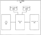
図1は、オーディオ受信機103、ラウドスピーカ105及び聴取者107を有する聴取エリア100の図を示す。オーディオ受信機103は、ラウドスピーカ105に連結でき、ラウドスピーカ105内の個々のトランスデューサ109を駆動して種々の音声ビームパターンを聴取エリア100内に放出することができる。一実施形態では、ラウドスピーカ105は、サウンドプログラムコンテンツ片の個々のチャネルを表すビームパターンを生成するように構成されてもよく、ラウドスピーカアレイとして駆動されることになる。例えば、(アレイとしての)ラウドスピーカ105は、サウンドプログラムコンテンツ片(例えば、楽曲又は動画用オーディオトラック)用の左前チャネル、右前チャネル及び前中央チャネルを表すビームパターンを生成することができる。ラウドスピーカ105は、キャビネット111を有し、トランスデューサ109は、図示されるようにベースプレート113が連結される、キャビネット111の底部102内に収容される。
FIG. 1 shows a diagram of a
図2Aは、一実施形態に係るオーディオ受信機103のコンポーネント図を示す。オーディオ受信機103は、ラウドスピーカ105内の1つ以上のトランスデューサ109を駆動可能な任意の電子デバイスとすることができる。例えば、オーディオ受信機103は、デスクトップコンピュータ、ラップトップコンピュータ、タブレット型コンピュータ、ホームシアタ受信機、セットトップボックス又はスマートフォンとすることができる。オーディオ受信機103は、ハードウェアプロセッサ201とメモリユニット203とを備えることができる。
FIG. 2A shows a component diagram of an
プロセッサ201及びメモリユニット203は、オーディオ受信機103の種々の機能及び動作を実施するのに必要な動作を行うプログラマブルデータ処理コンポーネント及びデータ記憶装置の任意の適切な組み合わせを一般的に示すのにここでは使用される。プロセッサ201は、スマートフォンに主に見られるアプリケーションプロセッサであってよく、メモリユニット203は、超小型電子技術による不揮発性ランダムアクセスメモリを示してもよい。オペレーティングシステムは、オーディオ受信機103の種々の機能に固有のアプリケーションプログラムとともにメモリユニット203に記憶される場合があり、これらのプログラムは、オーディオ受信機103の種々の機能を実行するために、プロセッサ201によって走らされるか、又は実行される。
オーディオ受信機103は、外部デバイス又はリモートデバイスから複数のオーディオ信号を受信する1つ以上のオーディオ入力205を備えることができる。例えば、オーディオ受信機103は、オーディオ信号をリモートサーバーからのストリーミングメディアサービスの一部として受信することができる。その代わりに、プロセッサ201は、ローカルに記憶された音楽又は動画ファイルをデコードして、オーディオ信号を取得することができる。オーディオ信号は、サウンドプログラムコンテンツ片(例えば、楽曲又は動画用オーディオトラック)の1つ以上のチャネルを表すことができる。例えば、マルチチャネルサウンドプログラムコンテンツ片の単一のチャネルに対応する単一の信号がオーディオ受信機103の入力205によって受信でき、この場合、複数の入力が、このコンテンツ片に対する複数のチャネルを受信するのに必要とされる場合がある。別の実施例では、単一の信号が、(サウンドプログラムコンテンツ片の)複数のチャネルに対応してもよいし、(サウンドプログラムコンテンツ片の)複数のチャネルをその中にエンコードしているか、又はその中に多重化していてもよい。
一実施形態では、オーディオ受信機103は、外部デバイス又はリモートデバイスから1つ以上のデジタルオーディオ信号を受信するデジタルオーディオ入力205Aを備えることができる。例えば、オーディオ入力205Aは、TOSLINKコネクタとしてもよいし、デジタル無線インターフェース(例えば、無線ローカルエリアネットワーク(WLAN)アダプタ又はBluetooth(登録商標)アダプタ)としてもよい。一実施形態では、オーディオ受信機103は、外部デバイスから1つ以上のアナログオーディオ信号を受信するアナログオーディオ入力205Bを備えることができる。例えば、オーディオ入力205Bは、ワイヤ又はコンジットを受容し、かつそれに対応するアナログ信号を受信するように設計された、バインディングポスト、ファーンスタッククリップ又はホノプラグとすることができる。
In one embodiment, the
一実施形態では、オーディオ受信機103は、ラウドスピーカ105と通信するためのインターフェース207を備えることができる。インターフェース207は、図1に示すように、ラウドスピーカ105と通信するために有線媒体(例えば、コンジット又はワイヤ)を利用することができる。別の実施形態では、インターフェース207は、ラウドスピーカ105と無線接続を通じて通信することができる。例えば、ネットワークインターフェース207は、IEEE802.11系規格、IEEE802.3、移動通信用のセルラーグローバルシステム(GSM)規格、セルラー符号分割多元接続(CDMA)規格、ロングタームエボリューション(LTE)規格、及び/又はBluetooth(登録商標)規格を含む、ラウドスピーカ105と通信するための1つ以上の無線プロトコル及び無線規格を利用することができる。
In one embodiment, the
図2Bに示すように、ラウドスピーカ105は、トランスデューサ駆動信号をオーディオ受信機103から対応するインターフェース213を通じて受信することができる。インターフェース207と同様に、インターフェース213は、IEEE802.11系規格、IEEE802.3、移動通信用のセルラーグローバルシステム(GSM)規格、セルラー符号分割多元接続(CDMA)規格、ロングタームエボリューション(LTE)規格、及び/又はBluetooth(登録商標)規格を含む、1つ以上の有線プロトコル及び有線規格、並びに/又は1つ以上の無線プロトコル及び無線規格を利用することができる。一部の実施形態では、駆動信号は、デジタル形式で受信されるので、トランスデューサ109を駆動するため、この場合、ラウドスピーカ105は、各トランスデューサ109を駆動するために駆動信号を増幅する前に駆動信号をアナログ形式に変換するために、パワーアンプ211の前に連結されたデジタルアナログ変換器(DAC)209を備えることができる。
As shown in FIG. 2B, the
オーディオ受信機103とは別個のものとして説明及び図示されたが、一部の実施形態では、オーディオ受信機103の1つ以上のコンポーネントは、ラウドスピーカ105内に集積されてもよい。例えば、後述するように、ラウドスピーカ105はまた、そのキャビネット111内に、ハードウェアプロセッサ201と、メモリユニット203と、1つ以上のオーディオ入力205とを備えることもできる。
Although described and illustrated as being separate from the
図1に示すように、ラウドスピーカ105は、スピーカキャビネット111内に複数のトランスデューサ109を収容し、複数のトランスデューサ109は、互いに対して環状構成で整列されてもよく、それによってラウドスピーカアレイを形成してもよい。特に、図示されるキャビネット111は円筒形であるが、他の実施形態では、キャビネット111は、多面体、切頭台、円錐、角錐、三角柱、六角柱、球形、円錐台形状又は任意の他の同様の形状を含む任意の形状とすることができる。キャビネット111は、少なくとも部分的に中空であってもよく、またトランスデューサ109をその内面又は外面上に搭載できるようにしてもよい。キャビネット111は、金属、金属合金、プラスチックポリマー又はこれらの一部の組み合わせを含む任意の好適な材料から作ることができる。
As shown in FIG. 1, the
図1及び図2Bに示すように、ラウドスピーカ105は、多数のトランスデューサ109を備えることができる。トランスデューサ109は、フルレンジドライバ、ミッドレンジドライバ、サブウーファー、ウーファー及びツイータの任意の組み合わせとすることができる。トランスデューサ109のそれぞれは、概して円筒状の磁気ギャップを通して軸方向に動くようにダイヤフラムに取り付けられたワイヤのコイル(例えば、ボイスコイル)を制約するフレキシブルサスペンションを介して、剛性バスケット又はフレームに接続されたダイヤフラム又はコーンを有してもよい。電気オーディオ信号がボイスコイルに印加されると、電流によってボイスコイル内に磁界が作り出され、可変電磁石となる。コイルとトランスデューサ109の磁気システムとが相互作用し、コイル(及び、したがって、取り付けられたコーン)を前後に動かす機械力が発生し、これにより、オーディオ受信機103などのオーディオ源から来る、印加された電気オーディオ信号の制御の下で音を再生する。電磁力学ラウドスピーカドライバがトランスデューサ109として使用されるものとして説明されているが、当業者は、圧電ドライバ、平面電磁ドライバ及び静電ドライバなどの他の種類のラウドスピーカドライバも可能であることを認識するであろう。
As shown in FIGS. 1 and 2B, the
それぞれのトランスデューサ109は、オーディオ源(例えば、オーディオ受信機103)から受信した個別かつ分離したオーディオ信号に応じて音を生成するように独立して個別に駆動されてもよい。トランスデューサ109の整列に関する知識を有し、異なるパラメータ及び設定(相対遅延及び相対エネルギーレベルを含む)に応じて独立して個別にトランスデューサ109を駆動させることで、ラウドスピーカ105は、オーディオ受信機103により出力されるサウンドプログラムコンテンツ片の各チャネルを正確に表す多くの指向性又はビームパターンを生成するようにアレイとして配置され、駆動され得る。例えば、一実施形態では、ラウドスピーカ105は、図3に示す1つ以上の指向性パターンを生成するようにアレイとして配置及び駆動されてもよい。ラウドスピーカ105によって生成された同時指向性パターンは、形状が異なるだけでなく、方向が異なってもよい。例えば、異なる指向性パターンは、聴取エリア100内の異なる方向に向けられてもよい。所望の指向性パターンを生成するのに必要なトランスデューサ駆動信号は、ビーム形成プロセスを実行するプロセッサ201(図2A参照)によって生成され得る。
Each
システムは、ラウドスピーカアレイの一部として配置及び駆動され得る多数のトランスデューサ109に関連付けて上記に説明してきたが、システムはまた、(キャビネット111に収容された)単一のトランスデューサのみで作動してもよい。このため、下記の説明では、時々、アレイとして構成及び駆動されるラウドスピーカ105に言及するが、一部の実施形態では、非アレイラウドスピーカが本明細書に記載する同様の方法で構成又は使用され得る。
Although the system has been described above in connection with a number of
上記に図示及び説明したように、ラウドスピーカ105は、アレイとして駆動されるように配置されたトランスデューサ109の単一の環を備えることができる。一実施形態では、トランスデューサ109の環内の各トランスデューサ109は、同じ種類又はモデル、例えば、複製とすることができる。トランスデューサ109の環は、音を環から「外向きに」放出するように配向され得、また、各トランスデューサ109がテーブル面から、又はラウドスピーカ105のベースプレート113の上面から垂直に等距離になるように、水平面に沿って(又は水平面内に置かれて)整列され得る。水平面に沿って整列されたトランスデューサ109の単一の環を備えることによって、ラウドスピーカ105によって放出された音の垂直制御は限定される場合がある。例えば、対応するトランスデューサ109に対するビーム形成パラメータ及び設定を調整することによって、トランスデューサ109の環によって放出された音を、水平方向に制御することができる。この制御により、水平面又は水平軸に沿った図3に示す指向性パターンを生成することが可能になる場合がある。しかしながら、トランスデューサ109の積層された複数の環がないため、この音の方向制御は、この水平面に限定される場合がある。したがって、ラウドスピーカ105によって垂直方向(水平軸又は水平面に垂直)に生成された音波は、限定されずに外向きに広がることができる。
As shown and described above, the
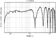
例えば、図4に示すように、トランスデューサ109によって放出された音は、最小限しか限定されずに垂直に拡散され得る。このシナリオでは、聴取者107の頭又は耳は、ラウドスピーカ105内のトランスデューサ109の環に対して約1mで、20°の角度で位置している。ラウドスピーカ105からの音の拡散には、1)下向きに、ラウドスピーカ105が設置されたテーブル面へ放出された音、及び2)直接、聴取者107に放出された音が含まれ得る。テーブル面に向かって放出された音は、テーブル面の表面から、聴取者107に向かって反射されることになる。したがって、ラウドスピーカ105からの反射音及び直接音の両方が、聴取者107によって感知される場合がある。反射経路は間接的であり、その結果、この実施例では直接経路より長くなるので、コムフィルタリング効果が聴取者107によって検出又は知覚され得る。コムフィルタリング効果は、同一であるが位相差を有する信号が加算されたときに生じる周波数応答におけるピーク及びトラフが創出されることとして定義され得る。望ましくないカラーレーションがされた音が、これらの信号の加算から生じ得る。例えば、図5は、ラウドスピーカ105に対して1mで、20°で(即ち、図4に示す聴取者107の位置で)検出された音に対する対数音圧対周波数のグラフを示す。このコムフィルタリング効果を示す1組のバンプ即ちピーク及びノッチ即ちトラフが、図5に示すグラフで観察される場合がある。バンプは、反射音が直接音と同相である場合の周波数に対応することがあり、ノッチは、反射音が直接音と位相がずれている場合の周波数に対応することがある。
For example, as shown in FIG. 4, the sound emitted by the
これらのバンプ及びノッチは、仰角又は角度(度)の変化とともに移動し得る。なぜなら、聴取者107の移動に基づいて、直接音と反射音との間の経路長差が急激に変化するためである。例えば、聴取者107は、図4に示す20°の仰角の代わりに、図6に示すように聴取者107がラウドスピーカ105に対して30度の角度又は仰角になるように立つことがある。30度の角度(仰角)で計測した音圧対周波数が、図7に示される。音圧対周波数の挙動におけるバンプ及びノッチは、仰角が変わるとともに移動するのが分かり、これは、異なる角度から目撃された図5及び図7のコムフィルタリング効果を示す図8の等高線グラフに図示される。より暗い陰影をもつ領域は高いSPL(バンプ)を表すが、より明るい陰影をもつ領域は低いSPL(ノッチ)を表す。バンプ及びノッチは、聴取者107がラウドスピーカ105に対する角度/位置を変えるにつれて、周波数にわたってシフトする。したがって、聴取者107がラウドスピーカ105に対して垂直方向に移動するにつれて、この聴取者107による音の知覚が変化する。聴取者107の移動中、又は異なる仰角での音において一貫性を欠くことは、望ましくない場合がある。
These bumps and notches may move with changes in elevation or angle (degrees). This is because, based on the movement of the
上記したように、コムフィルタリング効果は、反射音が聴取者107に行く途中で進行しなければならない距離が長いことによって引き起こされる反射音と直接音との間の位相差によって誘発される。コムフィルタリングに基づいた聴取者107に知覚可能なオーディオカラーレーションを低減するため、反射音と直接音との間の距離を短くしてもよい。例えば、トランスデューサ109の環は、トランスデューサ109によって放出される音が、テーブル面又は別の反射面での反射される前に、より短い距離又は最小限の距離しか進行しないように配向されてもよい。このように距離が縮小されると、直接音と反射音との間の遅延が短くなり、結果として聴取者107が最も位置しそうな位置/角度における音がより一貫したものとなる。トランスデューサ109からの反射経路と直接経路との間の差を最小化する技法を、例として以下に詳細に説明する。
As mentioned above, the comb filtering effect is induced by the phase difference between the reflected sound and the direct sound caused by the long distance the reflected sound must travel on its way to the
図9Aは、図4に示すラウドスピーカ105内のトランスデューサ109と比較して、集積されたラウドスピーカ109がキャビネット111の上面より、その底部の近くに移動したラウドスピーカ105を示す。一実施形態では、トランスデューサ109は、ラウドスピーカ105のキャビネット111の下端に固定されたベースプレート113に近接して位置してもよい。ベースプレート113は、ラウドスピーカ105がテーブル又は別の表面(例えば、床)に据えられている間、ラウドスピーカ105に安定性を付与する大きさの固体平坦構造体とすることができ、それによってキャビネット111を直立したままとすることができる。一部の実施形態では、ベースプレート113は、音がベースプレート113から反射できるよう、トランスデューサ109によって放出された音を受けるような大きさとすることができる。例えば、図9Aに示すように、トランスデューサ109によって下向きに向けられた音は、ラウドスピーカ109が置かれているテーブル面からではなく、ベースプレート113から反射され得る。ベースプレート113は、キャビネット111の底部102、例えば、直接その下端と連結されるものとして記載されてもよく、キャビネットの側壁の最も外側の垂直投影を越えて外側に延在してもよい。キャビネット111より直径が大きいものとして示されているが、一部の実施形態では、ベースプレート113は、キャビネット111と同じ直径とすることができる。これらの実施形態では、キャビネット111の底部102は、内側に(例えば、底部がベースプレート113に達するまで)湾曲又は切断されてもよく、またトランスデューサ109は、図1に示すようにキャビネット111の底部102のこの湾曲又は切り欠き部分内に位置してもよい。
FIG. 9A shows the
一部の実施形態では、発泡体などの吸収性材料901がベースプレート113の周りに、又はトランスデューサ109の周りに設置されてもよい。例えば、図9Cに示すように、スロット903を、トランスデューサ109とベースプレート113との間においてキャビネット111内に形成してもよい。スロット903内の吸収性材料901は、聴取者107と反対の方向にベースプレート113から反射された音の量を低減することができる(さもなければ、その音は、その後、キャビネット111から反射され、聴取者107に向かって戻ってくることになる)。一部の実施形態では、スロット903は、キャビネット111のベースの周りでキャビネット111を取り囲んでもよく、更に音の反射を低減するように特定の周波数範囲で共鳴を提供するように同調されてもよい。一部の実施形態では、スロット903は、更にキャビネット111からの音反射を除去すべく、特定の周波数範囲で音を抑制するように設計された吸収性材料901で被覆された共鳴器を形成してもよい。
In some embodiments, an
一実施形態では、図9D、図9Eに示すように、スクリーン905は、トランスデューサ109の下方に設置されてもよい。本実施形態では、スクリーン905は、トランスデューサ109によって放出された音用のローパスフィルタとして機能する有孔メッシュ(例えば、金属、金属合金又はプラスチック)とすることができる。特に、図9Dに最もよく示されるように、スクリーン905は、(図9Cに示すスロット903と同様に)ベースプレート113とトランスデューサ109との間のキャビネット111の下にキャビティ907を作り出すことができる。トランスデューサ109によって放出され、キャビネット111から反射する高周波数音は、スクリーン905によって減衰でき、聴取エリア100内に通過するのを防止できる。一実施形態では、スクリーン905の多孔性は、聴取エリア100に自由に入り得る周波数に限定するように調整され得る。
In one embodiment, as shown in FIGS. 9D and 9E, the
一実施形態では、トランスデューサ109のダイヤフラムの中心と反射面(例えば、ベースプレートの上面)との間の垂直距離Dは、図9Bに示すように8.0mm〜13.0mmとすることができる。例えば、一部の実施形態では、距離Dは、8.5mmとすることができるが、他の実施形態では、距離Dは11.5mm(又は、8.5mm〜11.5mmの間の任意の場所)とすることができる。他の実施形態では、距離Dは、4.0mm〜20.0mmとすることができる。図9A及び図9Bに示すように、音が反射される表面(例えば、ベースプレート113、又はベースプレート113が設けられていない他の場合といった、テーブル面又は床面自体)から近接に(即ち、距離D)位置させることによって、ラウドスピーカ105は、縮小された反射音の経路長を呈することができる。このように縮小された反射音の経路により、結果として、キャビネット111内に集積されたトランスデューサ109から発生する音に対して、反射音の経路長と直接音の経路長との差が低減される(例えば、反射音経路距離−直接音経路距離の差は、ゼロに近づく)。このように反射経路と直接経路との間の長さの差を最小化又は少なくとも低減することによって、結果的に、図10A及び図10Bのグラフに示すように音がより一貫したもの(例えば、一貫した周波数応答又は振幅応答)にすることができる。特に、図10A及び図10Bの両図におけるバンプ及びノッチは、大きさが減少し、かなり右に、人間の知覚限界の近くに移動した(例えば、あるバンプ及びノッチは10kHz超に移動している)。こうして、聴取者107によって知覚されるコムフィルタリング効果を低減できる。
In one embodiment, the vertical distance D between the center of the diaphragm of the
図9A〜図9Cでは単一のトランスデューサ109について考察及び図示したが、一部の実施形態では、複数のトランスデューサ109(例えば、トランスデューサのアレイ)の環状構成内の各トランスデューサ109は、キャビネット111の側部又は面に沿って、同様に配置されてもよい。これらの実施形態では、トランスデューサ109の環は、上記したように水平面に沿って整列されてもよいし、水平面内に置かれてもよい。
While FIGS. 9A-9C are discussed and illustrated for a
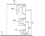
一部の実施形態では、距離D又は距離Dに使用される値の範囲は、対応するトランスデューサ109の半径(例えば、トランスデューサ109のダイヤフラムの半径)又はトランスデューサ109に使用される周波数範囲に基づいて選択され得る。特に、高周波数音は、反射によって引き起こされるコムフィルタリングにより影響されやすい場合がある。したがって、高周波数を生成するトランスデューサ109は、(低周波数音を生成するトランスデューサ109と比較して)その反射をより厳密に低減するために、より短い距離Dを必要とする場合がある。例えば、図11Aは、第1の組の周波数用に使用/設計された第1のトランスデューサ109A、第2の組の周波数用に使用/設計された第2のトランスデューサ109B、及び第3の組の周波数用に使用/設計された第3のトランスデューサ109Cを有するマルチウェイスピーカ105を示す。例えば、第1のトランスデューサ109Aは、高周波数成分(例えば、5kHz〜10kHz)用に使用/設計され得、第2のトランスデューサ109Bは、中間周波数成分(例えば、1kHz〜5kHz)用に使用/設計され得、また、第3のトランスデューサ109Cは、低周波数成分(例えば、100Hz〜1kHz)用に使用/設計され得る。トランスデューサ109A、109B、109Cのそれぞれのこれらの周波数範囲は、ラウドスピーカ105内に集積された1組のフィルタを使用して強制され得る。第1のトランスデューサ109Aによって生成された音波に対する波長は、トランスデューサ109B及び109Cによって生成された音波の波長より短いので、トランスデューサ109Aに関連付けられた距離DAは、トランスデューサ109B及び109Cにそれぞれ関連付けられた距離DB及びDCより短くなってもよい(例えば、トランスデューサ109B及び109Cは、コムフィルタリングに関連付けられたノッチが動作帯域幅内に入らずに、ラウドスピーカ105が置かれる反射面からより遠くに位置してもよい)。したがって、コムフィルタリング効果を低減するのに必要なトランスデューサ109と反射面との間の距離Dは、トランスデューサ109の大きさ/直径及び/又はトランスデューサ109によって再生されることを意図する周波数に基づくことができる。
In some embodiments, the range of values used for distance D or distance D is selected based on the radius of the corresponding transducer 109 (eg, the radius of the diaphragm of transducer 109) or the frequency range used for
単一のトランスデューサ109A、109B及び109Cで示されているが、図11Aに示すマルチウェイスピーカ105は、トランスデューサ109A、109B及び109Cのそれぞれの環を備えることができる。トランスデューサ109A、109B及び109Cの環それぞれは、別個の水平面内に整列され得る。
While shown with
更に、図11Aでは異なる3種類のトランスデューサ109A、109B及び109Cを備えるもの(即ち、3−ウェイラウドスピーカ105)として示されるが、他の実施形態では、ラウドスピーカ105は、任意の数の異なる種類のトランスデューサ109を備えることができる。特に、ラウドスピーカ105は、図11Bに示すようにN−ウェイアレイとすることができ、この場合、Nは1以上の整数である。図11Aと同様に、図11Bに示す本実施形態では、トランスデューサ109A〜109Nの各環と関連付けられた距離DA〜DNは、トランスデューサ109A〜109Nの大きさ/直径及び/又はトランスデューサ109A〜109Nによって再生されることを意図する周波数に基づくことができる。
Furthermore, although FIG. 11A is shown as comprising three
トランスデューサ109の中心と反射面との間を短い距離D(即ち、上記範囲内の値)にすることは、半径の小さいトランスデューサ109に対しては、トランスデューサ109を反射面の近くに移動させる(即ち、トランスデューサ109をキャビネット111に沿ってベースプレート113のより近くになるように配置する)ことによって達成できる場合があるが、トランスデューサ109が大きくなるにつれて、距離Dの値を所定の範囲内にすることができるかどうかは、困難又は不可能になる場合がある。例えば、トランスデューサ109の半径がDの閾値より大きい場合(例えば、閾値が12.0mmであり、トランスデューサ109の半径が13.0mmである)、単にトランスデューサ109を垂直方向にキャビネット111の面に沿って反射面のより近くまで移動するだけでは、Dの閾値を達成するのは不可能であろう。これらの状況では、後述するようにDの閾値を達成するために、更なる移動の自由度を採用してもよい。
A short distance D between the center of the
一部の実施形態では、ラウドスピーカ105内のトランスデューサ109の向きは、更に、トランスデューサ109と反射面との間の距離Dを縮小し、反射音経路を縮小し、結果として、反射音経路と直接音経路との差を低減するように調整され得る。例えば、図12は、一実施形態に係るラウドスピーカ105の側面図を示す。図9のラウドスピーカ105と同様に、図12に示すラウドスピーカ105は、キャビネット111の底部内又はその底部の周りで、ベースプレート113の近くに位置するトランスデューサ109の環を備える。トランスデューサ109の環は、図13の上から見た切断図に示すように、隣接する各対のトランスデューサ109の間隔を等しくして、キャビネット111の周囲を取り囲むことができる(あるいは、その周囲と同軸とすることができる)。
In some embodiments, the orientation of the
図12に示す例示的なラウドスピーカ105では、トランスデューサ109は、キャビネット111の底部102内に搭載されることによって、ベースプレート113に近接して位置する。本実施例の底部は、図示されるように円錐台形であり、上側ベースと下側ベースとを接合する側壁を有し、上側ベースは下側ベースより大きく、またベースプレート113は、図示されるように下側ベースと連結されている。この場合、トランスデューサ109のそれぞれは、側壁内の各開口部内に搭載されるものとして記載されてもよく、それによって、そのダイヤフラムがキャビネット111の本質的に外側にあるか、又はキャビネット111の外側から見通し線に沿って少なくともはっきりと見える。なお、示された距離Dはダイヤフラムの中心(例えば、外面の中心)からベースプレート113の上面まで下った垂直距離である。(底部102の)側壁は、その中に形成された多数の開口部を有し、それらは、環状構成で配置され、トランスデューサ109がそれぞれ搭載されている。図9A及び図9Bに関連して上記で述べたように、トランスデューサ109を、トランスデューサ109からの音が反射される表面の近くに位置決めすることによって、例えば、角度シータを制限しつつ距離Dを最小化することによってである。
In the
図14bを参照すると、角度シータは、同図に示すように、つまり、1)トランスデューサ109のダイヤフラムの平面、例えば、ダイヤフラムの周辺部がある平面と、2)テーブル面、あるいは、ベースプレート113が使用される場合は、ベースプレート113の上面に接する水平面との間の角度として定義され得る。トランスデューサ109のそれぞれの角度シータは、図14aに示すトランスデューサ109の直立配置と比較して、反射音の経路と直接音の経路との差を低減できるように、特定の範囲に制限され得る。下向きに傾けていないトランスデューサ109が図14Aに示されており、この場合、直立している、即ち、聴取者107に「直接対向する」ものとして記載され得、少なくとも90度の角度シータと、トランスデューサ109の中心と下方の反射面(例えば、テーブル面又はベースプレート113の上面)との距離D1を定義している。図14Bに示すように、トランスデューサ109を下向きに鋭角シータ(θ)で傾けると、トランスデューサ109の中心と反射面との距離D2(D2<D1)となる。したがって、トランスデューサ109を「前方に」その最下点の周りに回転(傾斜又は枢動)させることによって、そのダイヤフラムが反射面により一層向けられ、(ダイヤフラムの最下縁部は、図14Aと図14Bとの間に、例えば、反射面にできるだけ近くに固定されたままであるので)トランスデューサ109と反射面との距離Dが減少する。上記で述べたように、Dの縮小により、直接音の経路と反射音の経路との差が低減され、結果としてコムフィルタリングによって引き起こされるオーディオカラーレーションが低減される。反射音の経路の縮小は、図14Cで示され、回転していないトランスデューサ109からの実線は、角度シータθで傾斜されたトランスデューサ109からの破線より長くなる。こうして、更に距離D(例えば、トランスデューサ109の中心とベースプレート113又はキャビネット111の下の他の反射面のいずれかとの間の距離)を縮小し、結果として、反射経路を縮小するため、トランスデューサ109を、上述し図12にも示したように、ベースプレート113に向かって下向きに傾けることができる。
Referring to FIG. 14b, the angle theta is used as shown in the figure: 1) the plane of the diaphragm of the
上記したように、距離Dは、トランスデューサ109のそれぞれのダイヤフラムと反射面(例えば、ベースプレート113)との間の垂直距離である。一部の実施形態では、この距離Dは、ダイヤフラムの中心から反射面まで測定されてもよい。突出したダイヤフラムと平坦なダイヤフラムの両方で図示したが、一部の実施形態では、逆ダイヤフラム(inverted diaphragm)を使用してもよい。これらの実施形態では、距離Dは、逆ダイヤフラムの中心から、又はダイヤフラムの平面への法線に沿ってダイヤフラムの平面上に投影された中心から測定してもよく、この場合、ダイヤフラム平面は、ダイヤフラムの周辺部がある平面とすることができる。トランスデューサと関連付けられた別の平面は、(そのダイヤフラムの逆湾曲にかかわりなく)トランスデューサ109の前面によって定義された平面とすることができる。
As noted above, the distance D is the vertical distance between the respective diaphragm of the
トランスデューサ109を傾斜又は回転すると、距離Dが縮小され、それに対応して反射音経路が縮小され得るが、トランスデューサ109を反射面に向かって過度に回転すると、別個の所望しない効果が生じる場合がある。特に、トランスデューサ109を閾値を越えて回転させると、反射面又はキャビネット111から反射してトランスデューサ109に向かって戻る音によって共鳴が生じる場合がある。したがって、確実に、所望しない共鳴に遭遇しないように回転の下限を採用してもよい。例えば、トランスデューサ109は、30.0°〜50.0°の間で回転又は傾斜されてもよい(例えば、図14Bにおいて上記で定義したθは、30.0°〜50.0°とすることができる)。一実施形態では、トランスデューサ109は、37.5°〜42.5°の間で回転され得る(例えば、θは、37.5°〜42.5°とすることができる)。他の実施形態では、トランスデューサ109は、39.0°〜41.0°の間で回転され得る。トランスデューサ109の回転の角度シータは、トランスデューサ109に対する所望の距離又は閾値距離Dに基づいてもよい。
Tilting or rotating the
図15Aは、ラウドスピーカ105から1m離れて、水平から20°上向きである(図4参照)、直接経路に沿った(聴取者107の)位置で検出された音に対する対数音圧対周波数のグラフを示す。特に、図15Aのグラフは、トランスデューサ109の回転角度シータを45°にした図12に示すラウドスピーカ105によって放出された音を表す。このグラフでは、音声レベルは、可聴範囲内(即ち、20Hz〜10kHz)で比較的一貫している。同様に、単一のトランスデューサ109の図15Bの等高線グラフによれば、聴取者107が位置することになるほとんどの角度に対して垂直方向において比較的一貫している。例えば、聴取者107が0°である垂直位置(聴取者107がラウドスピーカ105のすぐ前に着座している)、及び45°〜60°の間の垂直位置(聴取者107がラウドスピーカ105の近くに立っている)に対して線形応答が図15Bの等高線グラフに示されている。特に、この等高線グラフのノッチは、可聴範囲の外側にほとんど移動しているか、又は聴取者107が位置しそうにない垂直角度まで移動している(例えば、聴取者107は、垂直角度90°でラウドスピーカ105のすぐ上方に立つことはないであろう)。
FIG. 15A is a graph of log sound pressure versus frequency for sound detected at a location (of the listener 107) along the direct path, 1 m away from the
上記で述べたように、トランスデューサ109を回転すると、トランスデューサ109の中心と反射面(例えば、ベースプレート113)との間の距離Dを短くすることができる。一部の実施形態では、回転角度又は回転範囲は、トランスデューサ109の周波数の組及びその大きさ又は直径に基づいて設定され得る。例えば、より大きいトランスデューサ109は、波長のより大きな音波を生成することができる。したがって、これらのより大きなトランスデューサ109に対するコムフィルタリングを緩和するのに必要な距離Dは、より小さいトランスデューサ109に対するコムフィルタリングを緩和するのに必要な距離Dより長くなる場合がある。これらのより大きなトランスデューサ109に対する距離Dは、より小さなトランスデューサ109と比較して長くなるので、この長い距離Dを達成するのに必要とされる、トランスデューサが傾斜される対応角度θは、過度な回転(又は過度な傾斜)を回避するために、長くなる(より少ない傾斜又は回転が必要とされる)場合がある。したがって、トランスデューサ109に対する回転角度θは、トランスデューサ109のダイヤフラムの大きさ又は直径及びトランスデューサ109によって出力されるのを所望される周波数の組に基づいて選択され得る。
As mentioned above, rotating the
上記したように、トランスデューサ109を、ラウドスピーカ105のキャビネット111の面に沿って位置決めするとともに傾けることにより、反射音経路の距離を縮小でき、反射音経路と直接音経路との差を低減でき、その結果、コムフィルタリング効果を低減できる。一部の実施形態では、コムフィルタリングを更に低減するためにホーンを利用することもできる。かかる実施形態では、ホーンにより、音がラウドスピーカ105のキャビネット111(内の開口部)から抜け出す(その後、聴取者107に向かって各直接経路及び反射経路に沿って移動する)地点を調整することができる。特に、音がキャビネット111から解放され聴取エリア100内に入る地点は、ラウドスピーカ105の製造中に反射面(例えば、ベースプレート113)に近接するように構成され得る。いくつかの異なるホーンの構成を以下に説明する。これらの構成のそれぞれは、依然としてコムフィルタリング効果を低減するとともに、ラウドスピーカ105用の小さいキャビネット111を維持しながら、より大きなトランスデューサ109(例えば、直径がより大きなダイヤフラム)、又はより数の多い、若しくはより少ないトランスデューサ109の使用を可能にすることができる。
As described above, by positioning and tilting the
図16Aは、ホーン115を有し、ベースプレート113を有しないラウドスピーカ105のキャビネット111の側切断図を示す。図16Bは、環状構成で配置された複数のトランスデューサ109を有するアレイとして構成され、アレイとして駆動されるように構成された図16Aのラウドスピーカ105の立面図又は斜視図を示す。この実施例では、トランスデューサ109は、(キャビネット111の側壁内の開口部内ではなく)キャビネット111の更に内部に、又はキャビネット111内に搭載又は配置され、ホーン115は、トランスデューサ109のダイヤフラムをキャビネット111の音出力開口部117に音響的に接続するように設けられている。トランスデューサ109がキャビネット111の側壁内の開口部内に搭載され、外側から見える図9Dの実施形態と対照的に、キャビネット111の外側から図16A、図16Bにおけるトランスデューサ109への「見通し線」が存在しない。ホーン115は、トランスデューサ109から下向きに、開口部117まで延在し、開口部117は、テーブル面又は床にあるキャビネット111の底部102の勾配側壁内に形成されている。本実施例では、底部102は円錐台形である。ホーン115は、トランスデューサ109からの音を、開口部117が位置するキャビネット111の側壁の内面に向けて、その地点で、その後、音は開口部117を通じて聴取エリア内に解放される。図示されるように、トランスデューサは依然としてキャビネット111の上端よりキャビネット111の下端に近い場合があるが、トランスデューサ109は、図12の実施形態と対照的に、(下端より上の)上昇位置にある。それにもかかわらず、トランスデューサ109によって放出された音は、依然としてキャビネット111から、真下の反射面に「近接した」又は十分近い地点で解放され得る。これは、音がそれ自体がベースプレート113に近接して位置決めされた開口部117から解放されるからである。一部の実施形態では、開口部117は、(距離Dはダイヤフラムとキャビネット111の下方の反射面との間を測定したものであった)図9B、図12、図14Bの実施形態に関連して上記したのと同じ垂直距離Dを得るように位置決め及び配向され得る。ここでホーンの実施形態については、所定の垂直距離D(開口部117の中心から垂直に下ってキャビネット111が置かれているテーブル面又は床まで)は、例えば、8.0mm〜13.0mmの間とすることができる。ここでホーンの実施形態の場合では、距離Dは、(図14Bの回転又は傾斜角度シータと類似して)部分的に開口部117を傾斜させることによって、例えば、開口部117が形成された(キャビネット111の)円錐台形の底部102の側壁の角度又は勾配を適切に定義することによって得られる場合がある。
FIG. 16A shows a side cutaway view of the
ホーン115及び開口部117は、トランスデューサ109によって生成された音に適応する種々の大きさに形成され得る。一実施形態では、ラウドスピーカ105内の複数のトランスデューサ109は、キャビネット111内に対応するホーン115及び開口部117を有して同様に構成され、アレイとして一体に構成され、また、アレイとして駆動されるように構成されてもよい。各トランスデューサ109からの音は、キャビネット111の下方の反射面(例えば、テーブル面若しくはキャビネット111が置かれている床又はベースプレート113)から所定距離Dにおいてキャビネット111から解放される。この距離Dは、開口部117の中心から(垂直下向きに)反射面まで測定され得る。音はこのようにベースプレート113に近接して放出されているので、反射音は、上記したように直接音の経路と同様の経路に沿って進行することができる。特に、開口部117から短い距離進行しただけで反射されるので、反射音の経路と直接音の経路における差は小さくでき、結果として、聴取者107に知覚できるコムフィルタリング効果が低減される。例えば、図16A及び図16Bに示すラウドスピーカ105に対応する図17の等高線グラフは、図8に示すコムフィルタリング効果と比較して、周波数及び垂直角度(聴取者107のあり得る垂直位置を規定する角度)にわたって滑らかで一貫したレベル差を示す。
The
図18は、別のホーンの実施形態に係るラウドスピーカ105のキャビネット111の切断図を示す。本実施例では、トランスデューサ109は、キャビネット111の側壁に、又はそれを貫通して搭載されるが、(例えば、図9Dの実施形態のように外側ではなく)内側に向けられている。換言すれば、ダイヤフラムの前方面は、キャビネット111内に対向している。対応するホーン115は、トランスデューサ109のダイヤフラムの前面にそれぞれ音響的に結合され、対応する開口部117まで各曲線に沿って下向きに延在する。本実施形態では、トランスデューサ109は、第1の方向に対向するが、ホーン115Aの湾曲により、音を開口部117から放出することができ、開口部117は、音を聴取エリア100内に第2の方向(第1の方向とは異なる)で放出するように向けられている。本実施形態におけるキャビネット111の開口部117は、図16A、図16Bのホーンの実施形態と関連して上記したのと同じように位置決め及び配向され得る。また、位相プラグ119が、高周波数音をリダイレクトし、反射及び打ち消しを回避するよう、図示されるように、トランスデューサ109とその各開口部117との間の音響経路内に追加され得る。図18のラウドスピーカ105に対応する図19の等高線グラフは、図8に示す望ましくないコムフィルタリング効果と比較して、周波数及び垂直聴取位置(垂直方向角度)にわたって滑らかで一貫したレベル差を示す。
FIG. 18 shows a cutaway view of the
図20は、更に別の実施形態に係るラウドスピーカ105のキャビネット111の切断図を示す。本実施例では、トランスデューサ109はまた、キャビネット111内に搭載されるが、(トランスデューサ109がキャビネット111の側壁に搭載され得る図18の実施形態のように横方向ではなく)下向きに向けられている。この配置により、図18の実施形態のホーンより短いホーン115を使用することを可能にすることができる。図21の等高線グラフに示すように、より短いホーン115は、やはり(上記した)ホーン115を使用する他の実施形態と比較して、本実施形態による円滑な応答に寄与することができる。一実施形態では、ホーン115の長さは、20.0mm〜45.0mmとすることができる。本実施形態におけるキャビネット111の開口部117はまた、キャビネット111の円錐台形の底部102の勾配側壁に形成されてもよく、反射面、例えばベースプレート113の上面に対してより短い距離Dを得るために、図16A、16Bのホーンの実施形態と関連して上記したのと同じに位置決め及び配向されてもよい。
FIG. 20 shows a cutaway view of a
図22は、更に別の実施形態に係るラウドスピーカ105のキャビネット111の切断図を示す。本実施例では、トランスデューサ109のそれぞれは、例えば、図20と同様に、キャビネット111内に搭載されるが、(各トランスデューサ109から放出された音を各開口部117に向ける)ホーン115は、図20のホーンより長く、かつより細くなる。一部の実施形態では、各トランスデューサ109それぞれに対して1つ以上のヘルムホルツ共鳴器121(例えば、800Hz共鳴器、3kHz共鳴器又は両方)の組み合わせを、位相プラグ119とともに使用することができる。共鳴器121は、音を吸収し反射を低減するために、ホーン115に沿って又は開口部117のすぐ外側に整列され得る。図23の等高線グラフに示すように、本実施形態のより長くより細いホーン115は、800Hz及び3kHzヘルムホルツ共鳴器121とともに、(垂直方向における様々な角度で)滑らかな周波数応答をもたらすことができる。
FIG. 22 shows a cutaway view of a
図24は、別の実施形態に係るラウドスピーカ105のキャビネット111内の、組み合わせトランスデューサ109とその位相プラグ119の切断図又は断面図を示す。本実施形態では、位相プラグ119は、各トランスデューサ109に隣接して設置され、かかる組み合わせトランスデューサ109及び位相プラグ119はそれぞれ、図示されるように完全にキャビネット111(の側壁の内側)内に位置することができる。一実施形態では、キャビネット111の外面に、又はベースプレート113にも連結された遮蔽デバイス2401が、トランスデューサ109に対して定位置に位相プラグ119を保持することができる。遮蔽デバイス2401は、キャビネット111の周辺部又は周囲の周りに延在でき、全トランスデューサ109(例えば、ラウドスピーカアレイの場合)の全位相プラグ119を保持するよう機能する環を形成する。位相プラグ119は、中心ハブ2405から延在するいくつかのフィン2403として形成されてもよい。フィン2403は、音を、(フィン2403のうち隣接するフィン間の空間を通じて)対応するトランスデューサ109のダイヤフラムから遮蔽デバイス2401内に形成された開口2407まで案内することができる。したがって、位相プラグ119は、音をトランスデューサ109から開口2407まで通すことができるように、図示されるようにトランスデューサ109のダイヤフラムを含むトランスデューサ109を囲むように成形され得る。やはり音をトランスデューサ109から開口部117までそれぞれ案内することによって、本実施形態の位相プラグ119はまた、トランスデューサ109の実効的な音声放射エリアを反射面(例えば、ラウドスピーカ105が置かれているベースプレート113又はテーブル面)の近くに配置することができる。上記で述べたように、トランスデューサ109の音声放射エリア又は音放射面を反射面の近くに位置決めすることによって、本実施形態におけるラウドスピーカ105は、反射音経路と直接音経路との差を低減でき、次いでコムフィルタリング効果を低減することができる。
FIG. 24 shows a cutaway or cross-sectional view of the
ここで、図25を参照すると、本実施形態では、ラウドスピーカ105は、仕切り2501を有する。仕切り2501は、剛性材料(例えば、金属、金属合金又はプラスチック)から作られてもよく、部分的にトランスデューサ109をブロックするようにキャビネット111の外面からキャビネット111の底部102の上に延在する(図25の仕切り2501によってブロックされることになる、キャビネット111の底部102とその中のトランスデューサ109の一例を示す図12を参照)。本実施例における仕切り2501は、(まっすぐ下向きに延在する)単純な円筒形であるが、その代わりに、キャビネット111を取り囲み、部分的にトランスデューサ109のそれぞれをブロックするように、異なる湾曲形状、例えば、スカート又はカーテンのような波状を有することができる。一実施形態では、仕切り2501は、図示されるように、その湾曲側壁に形成された多数の穴2503を含むことができ、それらは、種々な所望の周波数の音を通過させることができる大きさとすることができる。例えば、ベースプレート113から最も遠くに位置する穴2503の1つのグループ又はサブセットは、低周波数音(例えば、100Hz〜1kHz)を通過させることができる大きさとすることができるが、低周波数穴の下方にある穴2503の別のグループ又はサブセットは、中間周波数音(例えば、1kHz〜5kHz)を通過させることができる大きさとすることができる。本実施形態では、高周波数音は、仕切り2501の下端とベースプレート113との間に作り出された隙間2505の間を通過することができる。したがって、高周波数成分は、この成分を隙間2505に制限することによって、ベースプレート113の近くに押し込まれる。高周波数成分のベースプレート113(即ち、反射地点)の近くへの移動により、反射音経路が縮小され、結果として、上記で述べたように、特にこの形態のオーディオカラーレーションの影響を受けやすい高周波数成分に対するコムフィルタリングの知覚性は低減される。
Here, referring to FIG. 25, in the present embodiment, the
ここで、図26A、図26Bを参照すると、これらは、本発明の更に別の実施形態によるラウドスピーカ105のマルチウェイウェイバージョン又はアレイバージョンにおける音響ディバイダ2601の使用を図示する。ディバイダ2601は、図26Bの側面図に最もよく見られるように、キャビネット111の底部102をベースプレート113に接合する壁を形成する平坦片とすることができる。ディバイダ2601は、トランスデューサ109で始まり、長さ方向外向きに、例えば、(キャビネット111の垂直長手方向軸が走るキャビネットの中心から延びる半径rによって与えられた水平長さまで、延在する(図26b参照))。ディバイダ2601は、図示されるように、キャビネット111の最も外側の側壁によって画定される垂直境界に達する必要はない。トランスデューサ109の両側上の1対の隣接ディバイダ2601は、キャビネット111の底部102の表面及びベースプレートの上面とともに、トランスデューサ109用のホーンのように働くことができる。
Referring now to FIGS. 26A, 26B, these illustrate the use of
上述したように、本明細書に記載するラウドスピーカ105は、アレイとして構成及び駆動されると、従来のアレイより改善された性能をもたらす。特に、本明細書に提供されたラウドスピーカ105は、1)トランスデューサ109の垂直又は回転調整によってトランスデューサ109を反射面(例えば、ベースプレート113、又はテーブル面)の近くに移動することによって、又は、2)トランスデューサ109によって生成される音を、ホーン115及び反射面から所定距離にある開口部117を使用することによって反射面に近接する聴取エリア100内に解放されるように案内することのいずれかによって、聴取者107が知覚するコムフィルタリング効果を低減する。反射面とトランスデューサ109によって放出される音が聴取エリア100内に解放される地点との間の距離を縮小することによって、結果として音の反射経路を縮小し、直接音に対して遅延した反射音によって引き起こされるコムフィルタリング効果を低減する。したがって、図示及び記載されたラウドスピーカ105は、重大なオーディオカラーレーションが反射音によって引き起こされることなく、反射面上に設置され得る。
As mentioned above, the
また上記したように、環状に配置されたトランスデューサ109のアレイを使用することで、ラウドスピーカ105によって生成された音の水平制御を提供するのを助けることができる。特に、ラウドスピーカ105によって生成された音は、水平面内に十分に定義された音声ビームの形成を助けることができる。この水平制御は、トランスデューサ109をキャビネット111の下の音反射面に近接して位置決めすることによって提供される(図面に示された等高線グラフによって明示されたように)改善された垂直制御と組み合わせて、ラウドスピーカ105が音の多軸制御を提供するのを可能にする。しかしながら、多数のトランスデューサ109と関連して上記したが、一部の実施形態では、単一のトランスデューサ109がキャビネット111内で使用されてもよい。これらの実施形態では、ラウドスピーカ105は、アレイの代わりに、ワンウェイ又はマルチウェイスピーカとなることが理解される。単一のトランスデューサ109を有するラウドスピーカ105は依然として、上記したようにトランスデューサ109の注意深い設置及び配向によって音の垂直制御を提供することができる。
Also, as noted above, the use of an array of annularly arranged
特定の実施形態について説明し添付の図面に示してきたが、当然のことながら、このような実施形態は大まかな発明を単に例示するものであってそれを限定するものではなく、また、本発明は図示及び説明した特定の構成及び配置には限定されない。なぜならば、他の種々の変更が当業者に想起され得るからである。したがって、説明は、限定的ではなく例示的であるとみなされる。 While specific embodiments have been described and illustrated in the accompanying drawings, it will be appreciated that such embodiments are merely illustrative of the broad invention and not limiting. Is not limited to the specific configuration and arrangement shown and described. Because other various modifications may occur to those skilled in the art. Accordingly, the description is considered to be illustrative rather than limiting.
Claims (19)
前記トランスデューサを収容するキャビネットであって、前記複数のトランスデューサが前記キャビネットと環状構成で連結され、前記環状構成は、前記複数のトランスデューサのうち各トランスデューサによって放出された音が、前記キャビネットが置かれるテーブル面又は床から所定距離で前記キャビネットから前記聴取エリア内に解放されるような構成であるキャビネットと、を備え、
前記所定距離は、4.0mm〜20.0mmであり、前記複数のトランスデューサの各トランスデューサのダイヤフラムが前記キャビネットの底部に向かって傾斜されている、ラウドスピーカ。 Multiple transducers emitting sound into the listening area;
A cabinet for accommodating the transducers, wherein the plurality of transducers are connected to the cabinet in an annular configuration, and the annular configuration is a table on which the sound emitted by each of the plurality of transducers is placed on the cabinet A cabinet configured to be released from the cabinet into the listening area at a predetermined distance from a surface or floor ,
Wherein the predetermined distance is 4.0Mm~20.0Mm, diaphragm each transducer of said plurality of transducers that are inclined towards the bottom of the cabinet, the loudspeaker.
前記キャビネットに搭載され、前記複数のトランスデューサから音を、それぞれ、前記キャビネットの前記側壁内に形成された複数の音出力開口部それぞれに案内するように連結された複数のホーンを更に備える、請求項1に記載のラウドスピーカ。 The bottom of the cabinet is frusto-conical and has a side wall joining an upper base and a lower base, the upper base is larger than the lower base, and a base plate is connected to the lower base. A speaker,
Claim further comprising: a plurality of horns mounted on the cabinet and coupled to guide sound from the plurality of transducers to respective plurality of sound output openings respectively formed in the sidewall of the cabinet. The loudspeaker according to 1.
前記トランスデューサを収容するキャビネットと、
前記キャビネットを直立位置に安定させるベースプレートであって、前記キャビネットの底部に連結されたベースプレートと、を備え、
前記複数のトランスデューサが前記キャビネットと環状構成で連結され、前記環状構成は、前記複数のトランスデューサのうち各トランスデューサによって放出された音が、前記ベースプレートから所定距離において前記キャビネットから前記聴取エリア内に解放されるような構成であり、
前記所定距離は、4.0mm〜20.0mmの間であり、
前記環状構成のトランスデューサは、各トランスデューサに対して、a)前記各トランスデューサのダイヤフラムの周辺部がある平面と、b)前記ベースプレートの上面の水平面との間で所定鋭角をなすように下向きに傾斜されている、ラウドスピーカ。 Multiple transducers emitting sound into the listening area;
A cabinet for containing the transducer;
A base plate for stabilizing the cabinet in an upright position, the base plate being connected to the bottom of the cabinet;
The plurality of transducers are coupled to the cabinet in an annular configuration, and the annular configuration is such that sound emitted by each of the plurality of transducers is released from the cabinet into the listening area at a predetermined distance from the base plate so that configuration der is,
The predetermined distance is between 4.0 mm and 20.0 mm,
The transducers in the annular configuration are inclined downward to each transducer so as to form a predetermined acute angle between: a) a plane with the periphery of the diaphragm of each transducer and b) a horizontal surface of the top surface of the base plate and that, loud speaker.
前記トランスデューサを収容するキャビネットとを備え、前記トランスデューサは前記キャビネットと連結されるとともに、前記キャビネットの上端より前記キャビネットの下端に近くにあり、前記下端は、テーブル面又は床の上に置かれるものであり、前記トランスデューサは、直立している前記トランスデューサと比較して、前記トランスデューサからの音の前記テーブル面又は床からの反射によって引き起こされるコムフィルタリングを低減するように、前記下端に向かって下向きに所定鋭角で傾けられており、
前記トランスデューサによって前記キャビネットから放出された音が、前記テーブル面又は前記床より4.0mm〜20.0mmの所定の距離にある前記聴取エリアへ向かう、ラウドスピーカ。 A transducer that emits sound into the listening area;
A cabinet for accommodating the transducer, the transducer being connected to the cabinet and being closer to a lower end of the cabinet than an upper end of the cabinet, the lower end being placed on a table surface or floor And the transducer is directed downwardly toward the lower end to reduce comb filtering caused by reflection of sound from the transducer from the table surface or floor as compared to the transducer in an upright position. It is tilted at an acute angle,
A loudspeaker , wherein the sound emitted from the cabinet by the transducer is directed to the listening area at a predetermined distance of 4.0 mm to 20.0 mm from the table surface or the floor .
前記複数のトランスデューサを収容するキャビネットであって、前記複数のトランスデューサの各トランスデューサが前記キャビネットに連結されるとともに前記キャビネットの完全に内部にあり、テーブル面又は床の上に置かれる下端を有するキャビネットと、
開口部の中心から前記キャビネットの下端が置かれる前記テーブル面又は床までの所定の垂直距離に位置決めされた前記キャビネットの側部内の開口部と、
前記複数のトランスデューサ内の一のトランスデューサからの音が前記開口部を通じて最初に前記聴取エリア内に解放されるように前記トランスデューサからの音を前記開口部まで案内するホーンと、を備えたラウドスピーカであって、
前記所定の垂直距離は、4.0mm〜20.0mmの間であり、
前記複数のトランスデューサの各トランスデューサは、環状構成で前記キャビネットの側壁内に形成された複数の開口部内にそれぞれ搭載される、ラウドスピーカ。 Multiple transducers emitting sound into the listening area;
A cabinet for housing the plurality of transducers, each transducer of said plurality of transducers located inside completely in the cabinet while being connected to the cabinet, and the cabinet having a lower end which is placed on the table surface or floor ,
An opening in the side of the cabinet positioned at a predetermined vertical distance from the center of the opening to the table surface or floor where the lower end of the cabinet is placed;
In loudspeaker and a horn for guiding to the opening the sound from the transducer to be released first in the listening area through sound the opening from one transducers in the plurality of transducers There,
The predetermined vertical distance is between 4.0 mm and 20.0 mm,
A loudspeaker, wherein each transducer of the plurality of transducers is respectively mounted in a plurality of openings formed in the sidewall of the cabinet in an annular configuration .
Applications Claiming Priority (3)
| Application Number | Priority Date | Filing Date | Title |
|---|---|---|---|
| US201462057992P | 2014-09-30 | 2014-09-30 | |
| US62/057,992 | 2014-09-30 | ||
| PCT/US2015/053025 WO2016054100A1 (en) | 2014-09-30 | 2015-09-29 | Loudspeaker with reduced audio coloration caused by reflections from a surface |
Related Child Applications (2)
| Application Number | Title | Priority Date | Filing Date |
|---|---|---|---|
| JP2018123988A Division JP6584596B2 (en) | 2014-09-30 | 2018-06-29 | Loudspeaker with reduced audio coloration caused by reflection from the surface |
| JP2018123987A Division JP6657323B2 (en) | 2014-09-30 | 2018-06-29 | Loudspeaker with reduced audio coloration caused by reflection from the surface |
Publications (2)
| Publication Number | Publication Date |
|---|---|
| JP2017536001A JP2017536001A (en) | 2017-11-30 |
| JP6526185B2 true JP6526185B2 (en) | 2019-06-05 |
Family
ID=54291705
Family Applications (5)
| Application Number | Title | Priority Date | Filing Date |
|---|---|---|---|
| JP2017517245A Active JP6526185B2 (en) | 2014-09-30 | 2015-09-29 | Loudspeaker with reduced audio coloration caused by surface reflections |
| JP2018123987A Active JP6657323B2 (en) | 2014-09-30 | 2018-06-29 | Loudspeaker with reduced audio coloration caused by reflection from the surface |
| JP2018123988A Active JP6584596B2 (en) | 2014-09-30 | 2018-06-29 | Loudspeaker with reduced audio coloration caused by reflection from the surface |
| JP2020017664A Active JP7066765B2 (en) | 2014-09-30 | 2020-02-05 | Loudspeakers with reduced audio coloration caused by surface reflections |
| JP2022073086A Pending JP2022106857A (en) | 2014-09-30 | 2022-04-27 | Loudspeaker with reduced audio coloration caused by surface reflection |
Family Applications After (4)
| Application Number | Title | Priority Date | Filing Date |
|---|---|---|---|
| JP2018123987A Active JP6657323B2 (en) | 2014-09-30 | 2018-06-29 | Loudspeaker with reduced audio coloration caused by reflection from the surface |
| JP2018123988A Active JP6584596B2 (en) | 2014-09-30 | 2018-06-29 | Loudspeaker with reduced audio coloration caused by reflection from the surface |
| JP2020017664A Active JP7066765B2 (en) | 2014-09-30 | 2020-02-05 | Loudspeakers with reduced audio coloration caused by surface reflections |
| JP2022073086A Pending JP2022106857A (en) | 2014-09-30 | 2022-04-27 | Loudspeaker with reduced audio coloration caused by surface reflection |
Country Status (6)
| Country | Link |
|---|---|
| US (5) | US10652650B2 (en) |
| EP (3) | EP3416406A1 (en) |
| JP (5) | JP6526185B2 (en) |
| KR (4) | KR101973488B1 (en) |
| CN (5) | CN108848432B (en) |
| WO (1) | WO2016054100A1 (en) |
Cited By (4)
| Publication number | Priority date | Publication date | Assignee | Title |
|---|---|---|---|---|
| US10631071B2 (en) | 2016-09-23 | 2020-04-21 | Apple Inc. | Cantilevered foot for electronic device |
| US10652650B2 (en) | 2014-09-30 | 2020-05-12 | Apple Inc. | Loudspeaker with reduced audio coloration caused by reflections from a surface |
| US10728652B2 (en) | 2014-09-30 | 2020-07-28 | Apple Inc. | Adaptive array speaker |
| US11256338B2 (en) | 2014-09-30 | 2022-02-22 | Apple Inc. | Voice-controlled electronic device |
Families Citing this family (12)
| Publication number | Priority date | Publication date | Assignee | Title |
|---|---|---|---|---|
| GB2554815B (en) * | 2016-10-03 | 2021-03-31 | Google Llc | Voice-activated electronic device assembly with separable base |
| US10531196B2 (en) * | 2017-06-02 | 2020-01-07 | Apple Inc. | Spatially ducking audio produced through a beamforming loudspeaker array |
| CN107333206B (en) * | 2017-06-12 | 2023-11-07 | 歌尔股份有限公司 | Integral sound box and control method thereof |
| USD868761S1 (en) * | 2017-08-29 | 2019-12-03 | Amazon Technologies, Inc. | Device cover |
| CN109996141A (en) * | 2018-01-03 | 2019-07-09 | 深圳市冠旭电子股份有限公司 | Speaker |
| CN108391196B (en) * | 2018-03-19 | 2021-05-07 | 深圳市冠旭电子股份有限公司 | Audio signal processing device and sound box |
| KR102519742B1 (en) | 2018-08-28 | 2023-04-11 | 삼성전자주식회사 | An electronic device including a speaker module, and a lighting device |
| KR102571518B1 (en) * | 2018-10-17 | 2023-08-28 | 삼성전자주식회사 | Electronic device including a plurality of speaker |
| JP7147584B2 (en) * | 2019-01-23 | 2022-10-05 | 浜名湖電装株式会社 | alarm sound generator |
| JP7341755B2 (en) * | 2019-07-05 | 2023-09-11 | 清水建設株式会社 | Acoustic reflector for local sound field support and local sound field support device |
| WO2021060585A1 (en) * | 2019-09-27 | 2021-04-01 | 엘지전자 주식회사 | Sound output device and image display device |
| FR3110799B1 (en) * | 2020-05-25 | 2023-06-23 | Sagemcom Broadband Sas | Generic Acoustic Enclosure |
Family Cites Families (290)
| Publication number | Priority date | Publication date | Assignee | Title |
|---|---|---|---|---|
| GB492098A (en) | 1936-03-10 | 1938-09-12 | Telefunken Gmbh | Improvements in or relating to sound radiating systems |
| US2831051A (en) | 1953-10-05 | 1958-04-15 | Edward D Teikowski | Vibrato producing loud speaker |
| US3054856A (en) | 1959-02-24 | 1962-09-18 | Arany Donald | Sound reproducing system |
| NL267133A (en) | 1960-07-15 | |||
| US3500953A (en) | 1968-12-04 | 1970-03-17 | Uolevi L Lahti | Loudspeaker system |
| US3653191A (en) | 1969-10-16 | 1972-04-04 | Gardner Denver Co | Receiver-separator unit for liquid injected gas compressor |
| JPS5249324B1 (en) | 1970-06-05 | 1977-12-16 | ||
| US3816672A (en) * | 1970-07-06 | 1974-06-11 | K Peter | Sound reproduction system |
| US3818138A (en) * | 1971-07-26 | 1974-06-18 | A Sperrazza | Barrel shaped speaker enclosure |
| JPS5136931B2 (en) | 1972-04-22 | 1976-10-13 | ||
| US3815707A (en) | 1972-12-08 | 1974-06-11 | Epicure Prod Inc | Speaker enclosure |
| DE2435944C3 (en) * | 1974-07-25 | 1985-07-18 | Poensgen, Karl Otto, 8000 München | Hi-Fi speaker box |
| US3931867A (en) | 1975-02-12 | 1976-01-13 | Electrostatic Research Corporation | Wide range speaker system |
| US4051919A (en) | 1975-12-08 | 1977-10-04 | John M. Buettner | High fidelity speaker enclosure |
| US4073365A (en) | 1977-07-11 | 1978-02-14 | Johnson Joseph W | Speaker system |
| US4348549A (en) * | 1978-02-06 | 1982-09-07 | Emmanuel Berlant | Loudspeaker system |
| US4223760A (en) * | 1978-04-24 | 1980-09-23 | Letourneau Ted L | Loudspeaker assembly |
| US4369949A (en) | 1980-05-27 | 1983-01-25 | Cbs Industries | Loudspeaker pedestal |
| JPS57132498A (en) | 1981-02-09 | 1982-08-16 | Mitsubishi Electric Corp | Low pass filter for multi-way type speaker system |
| JPS60169989U (en) | 1984-04-18 | 1985-11-11 | 株式会社明電舎 | data acquisition circuit |
| JPS60177632U (en) | 1984-04-27 | 1985-11-26 | 昭和電線電纜株式会社 | Insulated connections of power cables |
| US4673057A (en) | 1984-11-13 | 1987-06-16 | Glassco John M | Geometrical transducer arrangements |
| US4574906A (en) | 1984-11-15 | 1986-03-11 | Audio Technica U.S., Inc. | Outdoor speaker |
| US4733749A (en) * | 1986-02-26 | 1988-03-29 | Electro-Voice, Inc. | High output loudspeaker for low frequency reproduction |
| US4923031A (en) * | 1986-02-26 | 1990-05-08 | Electro-Voice, Incorporated | High output loudspeaker system |
| US4810997A (en) | 1986-03-20 | 1989-03-07 | Kabushiki Kaisha Sankyo Seiki Seisakusho | Small sound generating device |
| JPH0357323Y2 (en) | 1986-06-10 | 1991-12-26 | ||
| DE3623092C1 (en) | 1986-07-09 | 1988-02-04 | Wandel & Goltermann | Omnidirectional horn speaker |
| US4796009A (en) * | 1987-03-09 | 1989-01-03 | Alerting Communicators Of America | Electronic warning apparatus |
| FR2627341B1 (en) | 1988-02-12 | 1994-07-01 | Giusto Marc | IMPROVEMENTS ON SOUND LOUDSPEAKERS |
| DE3812244C1 (en) * | 1988-04-13 | 1989-11-09 | Honeywell-Elac-Nautik Gmbh, 2300 Kiel, De | |
| FR2632801A1 (en) | 1988-06-14 | 1989-12-15 | Voise Serge | Adapter for curvilinear acoustics |
| FI81471C (en) * | 1988-11-08 | 1990-10-10 | Timo Tarkkonen | HOEGTALARE GIVANDE ETT TREDIMENSIONELLT STEREOLJUDINTRYCK. |
| JPH02218295A (en) * | 1989-02-20 | 1990-08-30 | Canon Inc | Audio output device |
| JPH03284096A (en) | 1990-03-30 | 1991-12-13 | Matsushita Electric Works Ltd | Cabinet containing speaker |
| US5146508A (en) * | 1990-09-07 | 1992-09-08 | Federal Signal Corporation | Omindirectional modular siren |
| US5123500A (en) | 1991-03-06 | 1992-06-23 | Malhoit Thomas A | Loudspeaker enclosure |
| JPH04329799A (en) | 1991-05-02 | 1992-11-18 | Matsushita Electric Ind Co Ltd | Horn speaker |
| US5226326A (en) | 1991-05-31 | 1993-07-13 | Environmental Stress Screening Corp. | Vibration chamber |
| US5451726A (en) | 1991-06-25 | 1995-09-19 | Eclipse Research Corporation | Omnidirectional speaker system |
| US5550110A (en) | 1992-04-22 | 1996-08-27 | Warner-Lambert Company | Endothelin Antagonists II |
| CN2137848Y (en) | 1992-04-30 | 1993-07-07 | 林智文 | Two-epitaxy sound-guiding tube low voice box |
| DE69329925T2 (en) | 1992-11-18 | 2001-05-31 | Matsushita Electric Ind Co Ltd | Television receiver |
| WO1994019915A1 (en) * | 1993-02-25 | 1994-09-01 | Heinz Ralph D | Multiple-driver single horn loudspeaker |
| DE9313435U1 (en) | 1993-09-07 | 1993-12-02 | Wacker Hans Ulrich Dipl Ing | Decorative column for holding a subwoofer system |
| JPH07143588A (en) * | 1993-11-12 | 1995-06-02 | Hisaji Nakamura | Vertical array type speaker equipment |
| US5527907A (en) | 1993-11-19 | 1996-06-18 | Abbott Laboratories | Macrolide immunomodulators |
| AUPM282493A0 (en) | 1993-12-06 | 1994-01-06 | Robert Bosch (Australia) Proprietary Ltd. | A siren unit |
| US5502772A (en) * | 1994-07-18 | 1996-03-26 | Felder; Charles J. | Speaker having improved sound square, sound bank, sound angle, sound wedge and sound radiators |
| JPH0970092A (en) | 1995-09-01 | 1997-03-11 | Saalogic:Kk | Point sound source, non-oriented speaker system |
| US5704578A (en) | 1995-11-03 | 1998-01-06 | Jbl Incorporated | Front-locking swivel ball loudspeaker mount |
| DE29602961U1 (en) | 1996-02-20 | 1996-04-04 | Schlenzig Dieter | Sound-light combination device |
| JPH09271095A (en) | 1996-03-29 | 1997-10-14 | Aiwa Co Ltd | Acoustic device |
| US5684380A (en) | 1996-07-26 | 1997-11-04 | Delco Electronics Corp. | Oil cooled high power inductive coupler |
| EP0919107A1 (en) | 1996-08-12 | 1999-06-02 | CARVER, Robert Weir | High back emf, high pressure subwoofer |
| US6356642B1 (en) | 1996-12-04 | 2002-03-12 | Murata Manufacturing Co., Ltd | Multi-speaker system |
| US5995634A (en) | 1997-06-02 | 1999-11-30 | Zwolski; Scott A. | Speaker and lamp combination |
| US5875255A (en) * | 1997-08-28 | 1999-02-23 | Campbell; Paul G. | High power electroacoustic speaker system having wide band frequency response |
| US5872339A (en) | 1997-08-28 | 1999-02-16 | Hanson; Charles Anthony | High performance loudspeaker system |
| AU1173799A (en) | 1997-11-19 | 1999-06-07 | Sakuji Fukuda | Speaker system |
| US5975236A (en) * | 1998-01-08 | 1999-11-02 | Yamamoto; Shuji | Speaker assembly |
| FI981409A (en) | 1998-06-17 | 1999-12-18 | Genelec Oy | Method and apparatus for reducing acoustic reflection in a room |
| CN1181704C (en) | 1998-09-24 | 2004-12-22 | 美国技术公司 | Parametric loudspeaker with electro-acoustical disphragm transducer |
| US20020057819A1 (en) | 1998-09-25 | 2002-05-16 | Czerwinski Eugene J. | High frequency compression drivers |
| US6431308B1 (en) | 1998-12-11 | 2002-08-13 | Edward G. Vollmer | High fidelity small omnidirectional loudspeaker |
| US6411718B1 (en) * | 1999-04-28 | 2002-06-25 | Sound Physics Labs, Inc. | Sound reproduction employing unity summation aperture loudspeakers |
| AU4280100A (en) * | 1999-05-01 | 2000-11-17 | Brand Marketing & Communications Group | Loudspeaker system |
| US6343133B1 (en) | 1999-07-22 | 2002-01-29 | Alan Brock Adamson | Axially propagating mid and high frequency loudspeaker systems |
| US6570494B1 (en) | 1999-12-01 | 2003-05-27 | Kenneth Charles Leftridge, Sr. | Mosquito guard |
| IT1314660B1 (en) | 2000-03-21 | 2002-12-31 | Outline Snc Di Noselli & C | IMPROVED BROADBAND DIFFUSER WITH HIGH EFFICIENCY AND HIGH DIRECTIVITY |
| US6393131B1 (en) | 2000-06-16 | 2002-05-21 | Scott Michael Rexroat | Loudspeaker |
| US6415036B1 (en) | 2000-08-24 | 2002-07-02 | Thomson Licensing, S.A. | Apparatus for reducing vibrations generated by a loudspeaker in a television cabinet |
| US6493456B1 (en) | 2000-10-18 | 2002-12-10 | Telefonaktiebolaget L.M. Ericsson | Thin speaker assemblies including laterally offset resonator cavities and personal electronic devices including the same |
| US7433483B2 (en) | 2001-02-09 | 2008-10-07 | Thx Ltd. | Narrow profile speaker configurations and systems |
| US8477958B2 (en) | 2001-02-26 | 2013-07-02 | 777388 Ontario Limited | Networked sound masking system |
| US7046816B2 (en) * | 2001-09-18 | 2006-05-16 | Vandersteen Richard J | Coincident source stereo speaker |
| US8718310B2 (en) | 2001-10-19 | 2014-05-06 | Qsc Holdings, Inc. | Multiple aperture speaker assembly |
| KR20030033695A (en) * | 2001-10-24 | 2003-05-01 | 삼성전기주식회사 | Two-way speaker of mobile phone |
| KR100445195B1 (en) * | 2002-03-20 | 2004-08-21 | 김종성 | Omnidirectional Speaker System |
| AU2003226142A1 (en) | 2002-03-28 | 2003-10-13 | Harman International Industries, Incorporated | Horn-loaded compression driver system |
| US7106868B2 (en) | 2002-05-15 | 2006-09-12 | Siemens Vdo Automotive Inc. | Active noise control for vehicle door noise |
| EP1547435B1 (en) | 2002-09-27 | 2019-08-21 | Boston Acoustics, Inc. | Loudspeaker |
| CN2580716Y (en) | 2002-10-18 | 2003-10-15 | 祝天祥 | All point direction and horn-like speaker |
| US7463746B2 (en) | 2003-03-31 | 2008-12-09 | Bose Corporation | Narrow opening electroacoustical transducing |
| KR100526599B1 (en) | 2003-04-01 | 2005-11-08 | 삼성전자주식회사 | Speaker |
| US20040213429A1 (en) | 2003-04-23 | 2004-10-28 | Gary Seidler | Fixture mounting assembly |
| US6666296B1 (en) | 2003-05-05 | 2003-12-23 | Wayman G. Mathis | Speaker assembly |
| JP4123046B2 (en) | 2003-05-13 | 2008-07-23 | ソニー株式会社 | Speaker device |
| JP4007255B2 (en) | 2003-06-02 | 2007-11-14 | ヤマハ株式会社 | Array speaker system |
| JP3891153B2 (en) | 2003-07-31 | 2007-03-14 | ソニー株式会社 | Telephone device |
| US20070152977A1 (en) | 2005-12-30 | 2007-07-05 | Apple Computer, Inc. | Illuminated touchpad |
| KR100573731B1 (en) | 2003-10-07 | 2006-04-24 | 학교법인고려중앙학원 | Apparatus for painting road surface |
| CN2703374Y (en) | 2004-05-10 | 2005-06-01 | 陈权江 | Air defense warning loudspeaker |
| US20070041599A1 (en) * | 2004-07-27 | 2007-02-22 | Gauthier Lloyd M | Quickly Installed Multiple Speaker Surround Sound System and Method |
| WO2006016156A1 (en) * | 2004-08-10 | 2006-02-16 | 1...Limited | Non-planar transducer arrays |
| JP4354887B2 (en) | 2004-08-27 | 2009-10-28 | 株式会社カギオカ | Tandem-driven speaker device and its structure |
| JP2006109345A (en) | 2004-10-08 | 2006-04-20 | Yamaha Corp | Speaker array and speaker module |
| US7360499B1 (en) * | 2004-12-21 | 2008-04-22 | Essi Corporation | Helmholtz resonator type marine signal |
| US20060147075A1 (en) * | 2004-12-31 | 2006-07-06 | Gingko Audio | Loudspeaker comprising coaxially-disposed drivers |
| JP4513765B2 (en) | 2005-04-15 | 2010-07-28 | 日本ビクター株式会社 | Electroacoustic transducer |
| JP2006304165A (en) | 2005-04-25 | 2006-11-02 | Yamaha Corp | Speaker array system |
| JP3943113B2 (en) | 2005-04-25 | 2007-07-11 | 株式会社エヌエスイー | Speaker box |
| US10021479B1 (en) | 2005-07-07 | 2018-07-10 | Paul Michael Craig | Non-horizontal multidirectional composite speaker |
| JP4745740B2 (en) * | 2005-07-12 | 2011-08-10 | パイオニア株式会社 | Speaker device |
| WO2007028094A1 (en) | 2005-09-02 | 2007-03-08 | Harman International Industries, Incorporated | Self-calibrating loudspeaker |
| US7814220B2 (en) | 2005-09-14 | 2010-10-12 | Sony Ericsson Mobile Communications Ab | User interface for an electronic device |
| JP5028786B2 (en) | 2005-11-02 | 2012-09-19 | ヤマハ株式会社 | Sound collector |
| JP4835138B2 (en) | 2005-12-09 | 2011-12-14 | ソニー株式会社 | Speaker device |
| JP4929703B2 (en) * | 2005-12-19 | 2012-05-09 | ヤマハ株式会社 | Sound emission and collection device |
| WO2007072757A1 (en) * | 2005-12-19 | 2007-06-28 | Yamaha Corporation | Sound emission and collection device |
| JP4797617B2 (en) * | 2005-12-22 | 2011-10-19 | ヤマハ株式会社 | Sound emission and collection device |
| CN101395565B (en) | 2005-12-30 | 2012-05-30 | 苹果公司 | Hand held device operated in a different mode operation and its operation method |
| EP2651147A1 (en) * | 2006-01-26 | 2013-10-16 | NEC Corporation | Electronic device and acoustic playback method |
| EP1814354B1 (en) | 2006-01-30 | 2017-04-26 | Sony Corporation | Speaker |
| GB2435206A (en) | 2006-02-15 | 2007-08-22 | John Kalli | Vibration isolating loudspeaker foot |
| US7760899B1 (en) | 2006-02-27 | 2010-07-20 | Graber Curtis E | Subwoofer with cascaded array of drivers arranged with staggered spacing |
| US7817016B2 (en) | 2006-03-23 | 2010-10-19 | Haase Edward H | Screw-in LED light and sound bulb |
| US7606377B2 (en) | 2006-05-12 | 2009-10-20 | Cirrus Logic, Inc. | Method and system for surround sound beam-forming using vertically displaced drivers |
| WO2007141677A2 (en) * | 2006-06-09 | 2007-12-13 | Koninklijke Philips Electronics N.V. | A device for and a method of generating audio data for transmission to a plurality of audio reproduction units |
| US7621369B2 (en) | 2006-06-16 | 2009-11-24 | Graber Curtis E | Acoustic energy projection system |
| JP2008035133A (en) * | 2006-07-27 | 2008-02-14 | Kenwood Corp | Audio system and speaker system |
| US8059856B2 (en) | 2006-07-31 | 2011-11-15 | Peavey Electronics Corporation | Methods and apparatus for providing a heat sink for a loudspeaker |
| JP4867516B2 (en) * | 2006-08-01 | 2012-02-01 | ヤマハ株式会社 | Audio conference system |
| US7757376B2 (en) | 2006-09-12 | 2010-07-20 | Tdk Corporation | Method for manufacturing of a magnetic circuit |
| ATE514290T1 (en) | 2006-10-16 | 2011-07-15 | Thx Ltd | LINE ARRAY SPEAKER SYSTEM CONFIGURATIONS AND CORRESPONDING SOUND PROCESSING |
| US7506721B2 (en) * | 2006-11-10 | 2009-03-24 | Moore Dana A | Convertible folded horn enclosure |
| US20080207123A1 (en) * | 2007-02-27 | 2008-08-28 | Andersen Jorgen W | Configurable means to provide wireless module customization |
| US8081775B2 (en) * | 2007-03-09 | 2011-12-20 | Robert Bosch Gmbh | Loudspeaker apparatus for radiating acoustic waves in a hemisphere around the centre axis |
| US7876274B2 (en) | 2007-06-21 | 2011-01-25 | Apple Inc. | Wireless handheld electronic device |
| GB2450719A (en) | 2007-07-04 | 2009-01-07 | Black & Decker Inc | Power cutter with engine controller and sensor means |
| US7997772B2 (en) | 2007-08-09 | 2011-08-16 | Fasst Products, Llc | Flameless candle with multimedia capabilities |
| US8712086B2 (en) | 2007-12-27 | 2014-04-29 | Motorola Mobility Llc | Acoustic reconfiguration devices and methods |
| US8175304B1 (en) * | 2008-02-12 | 2012-05-08 | North Donald J | Compact loudspeaker system |
| US8111585B1 (en) * | 2008-02-21 | 2012-02-07 | Graber Curtis E | Underwater acoustic transducer array and sound field shaping system |
| US20100022285A1 (en) | 2008-03-03 | 2010-01-28 | Wildcharge, Inc. | Apparatus and method for retrofitting a broad range of mobile devices to receive wireless power |
| WO2013093922A2 (en) | 2011-12-21 | 2013-06-27 | Powermat Technologies Ltd. | System and method for providing wireless power transfer functionality to an electrical device |
| US9628880B2 (en) | 2008-04-07 | 2017-04-18 | Koss Corporation | Wooden or other dielectric capacitive touch interface and loudspeaker having same |
| JP4364286B1 (en) | 2008-05-26 | 2009-11-11 | 株式会社東芝 | Electronics |
| US8094861B2 (en) | 2008-06-18 | 2012-01-10 | Nien-Tzu Liu | Speaker |
| CA2731972C (en) | 2008-08-14 | 2015-05-26 | Harman International Industries, Incorporated | Phase plug and acoustic lens for direct radiating loudspeaker |
| JP2010056684A (en) | 2008-08-26 | 2010-03-11 | Yamaha Corp | Audio signal processing device, speaker device, video display device, and control method |
| US8638314B2 (en) | 2008-10-17 | 2014-01-28 | Atmel Corporation | Capacitive touch buttons combined with electroluminescent lighting |
| US8422723B2 (en) | 2008-11-19 | 2013-04-16 | Panasonic Corporation | Loudspeaker and electronic device including loudspeaker |
| GB0821327D0 (en) * | 2008-11-21 | 2008-12-31 | Airsound Llp | Apparatus for reproduction of sound |
| US20100135505A1 (en) * | 2008-12-03 | 2010-06-03 | Graebener David J | Very high intelligibility mass notofication system |
| US9696405B1 (en) | 2008-12-05 | 2017-07-04 | Bae Systems Information And Electronic Systems Integration Inc. | Acoustic hostile fire indicator |
| CN201345722Y (en) | 2008-12-15 | 2009-11-11 | 元点音响(厦门)有限公司 | Low-frequency extension unit |
| TWI478460B (en) | 2009-01-06 | 2015-03-21 | Access Business Group Int Llc | Inductive power supply |
| EP2206879B1 (en) | 2009-01-12 | 2014-02-26 | Welltec A/S | Annular barrier and annular barrier system |
| WO2010104347A2 (en) | 2009-03-11 | 2010-09-16 | 거성전자산업(주) | Ceiling-embedded-type housing |
| CN102388626B (en) * | 2009-04-10 | 2015-02-25 | 皇家飞利浦电子股份有限公司 | Audio driver |
| US8139804B2 (en) | 2009-06-24 | 2012-03-20 | Bose Corporation | Electroacoustic transducing with a bridge phase plug |
| US9084070B2 (en) | 2009-07-22 | 2015-07-14 | Dolby Laboratories Licensing Corporation | System and method for automatic selection of audio configuration settings |
| CA2768397A1 (en) | 2009-07-24 | 2011-01-27 | Access Business Group International Llc | Power supply |
| US9111521B2 (en) * | 2009-09-11 | 2015-08-18 | Bose Corporation | Modular acoustic horns and horn arrays |
| US8917896B2 (en) | 2009-09-11 | 2014-12-23 | Bose Corporation | Automated customization of loudspeakers |
| SG170641A1 (en) * | 2009-10-30 | 2011-05-30 | Dream Infotainment Resources Pte Ltd | Omnidirectional speaker |
| US7837006B1 (en) * | 2009-11-04 | 2010-11-23 | Graber Curtis E | Enhanced spectrum acoustic energy projection system |
| CN102652436A (en) | 2009-12-14 | 2012-08-29 | 松下电器产业株式会社 | Speaker retaining mechanism and television receiver comprising same |
| US8385568B2 (en) | 2010-01-06 | 2013-02-26 | Apple Inc. | Low-profile speaker arrangements for compact electronic devices |
| CN101790124B (en) | 2010-01-10 | 2012-03-28 | 广州市锐丰音响科技股份有限公司 | Novel linear medium-high frequency compressed drive |
| JP5477393B2 (en) | 2010-02-05 | 2014-04-23 | 日立金属株式会社 | Magnetic circuit for non-contact charging device, power supply device, power receiving device, and non-contact charging device |
| US8885855B2 (en) * | 2010-02-08 | 2014-11-11 | Robert Bosch Gmbh | High directivity boundary microphone |
| GB2480226B (en) * | 2010-02-17 | 2014-03-12 | Randall Decourcy Hewitt | Active bass loudspeaker system |
| TW201133188A (en) | 2010-03-23 | 2011-10-01 | Hon Hai Prec Ind Co Ltd | Power source device |
| WO2011144499A1 (en) * | 2010-05-21 | 2011-11-24 | Bang & Olufsen A/S | Circular loudspeaker array with controllable directivity |
| DE102010021879A1 (en) * | 2010-05-28 | 2011-12-01 | Frank Held | Loudspeaker device with circumferential, funnel-shaped sound outlet opening |
| JP2012004692A (en) | 2010-06-15 | 2012-01-05 | Funai Electric Co Ltd | Display device |
| GB201011714D0 (en) | 2010-07-13 | 2010-08-25 | Roberts Davies R | Loudspeaker |
| CN201814129U (en) | 2010-07-28 | 2011-05-04 | 宁波方太厨具有限公司 | Cabinet with touch sense light |
| CN201813501U (en) | 2010-08-03 | 2011-04-27 | 李沫然 | Small-sized sound box structure |
| WO2012032335A1 (en) * | 2010-09-06 | 2012-03-15 | Cambridge Mechatronics Limited | Array loudspeaker system |
| US8913755B2 (en) | 2011-02-22 | 2014-12-16 | Dennis A. Tracy | Loudspeaker amplifier integration system |
| WO2012161844A1 (en) | 2011-02-28 | 2012-11-29 | B-Squares Electrics LLC | Electronic module, control module, and electronic module set |
| JP5673810B2 (en) | 2011-05-19 | 2015-02-18 | トヨタ自動車株式会社 | Power receiving device, power transmitting device, and power transmission system |
| WO2012172812A1 (en) | 2011-06-14 | 2012-12-20 | パナソニック株式会社 | Communication apparatus |
| JP5640911B2 (en) | 2011-06-30 | 2014-12-17 | ヤマハ株式会社 | Speaker array device |
| JP5596632B2 (en) * | 2011-07-01 | 2014-09-24 | 日本電信電話株式会社 | Filter coefficient determination device, local reproduction device, filter coefficient determination method, and program |
| JP2013062580A (en) * | 2011-09-12 | 2013-04-04 | Sony Corp | Sound reproduction device and sound reproduction method |
| KR101305303B1 (en) | 2011-09-21 | 2013-09-06 | 주식회사 한림포스텍 | Wireless power transfer apparatus and method the same |
| DE102011116991B4 (en) | 2011-10-26 | 2018-12-06 | Austriamicrosystems Ag | Noise suppression system and method for noise suppression |
| US20130142371A1 (en) | 2011-12-01 | 2013-06-06 | Jason P. Martin | Detachable Audio Speakers for Portable Devices and Methods for Manufacturing such Speakers |
| CN104067631A (en) | 2011-12-14 | 2014-09-24 | 福克朗公司 | Loudspeaker housing |
| US9107003B2 (en) | 2011-12-15 | 2015-08-11 | Apple Inc. | Extended duct with damping for improved speaker performance |
| EP2798857A1 (en) * | 2011-12-30 | 2014-11-05 | Libratone A/S | Multi lobe stereo loudspeaker in one cabinet |
| US9154869B2 (en) | 2012-01-04 | 2015-10-06 | Apple Inc. | Speaker with a large volume chamber and a smaller volume chamber |
| US20140341419A1 (en) | 2012-01-09 | 2014-11-20 | Actiwave Ab | Integrated loudspeaker assemblies |
| US9230732B2 (en) | 2012-01-17 | 2016-01-05 | Texas Instruments Incorporated | Wireless power transfer |
| US10143358B2 (en) | 2012-02-07 | 2018-12-04 | Treble Innovations, Llc | System and method for a magnetic endoscope |
| US9947333B1 (en) | 2012-02-10 | 2018-04-17 | Amazon Technologies, Inc. | Voice interaction architecture with intelligent background noise cancellation |
| WO2013124883A1 (en) * | 2012-02-21 | 2013-08-29 | パイオニア株式会社 | Speaker device |
| CN202424975U (en) | 2012-02-27 | 2012-09-05 | 华为终端有限公司 | Sound box and mobile terminal equipment |
| CN102655614A (en) | 2012-03-28 | 2012-09-05 | 广州惠威电器有限公司 | Novel wireless-surrounded sound box |
| TWI433423B (en) | 2012-03-30 | 2014-04-01 | Primax Electronics Ltd | Wireless charging device |
| EP2648309B1 (en) | 2012-04-03 | 2019-04-17 | Lite-On Technology Corporation | Comb-structured shielding layer and wireless charging transmitter thereof |
| WO2013155197A1 (en) | 2012-04-11 | 2013-10-17 | Waller James K | Adaptive rail power amplifier technology |
| US20130294638A1 (en) | 2012-05-01 | 2013-11-07 | Jorn Huseby | Speaker tower |
| AU2013262488A1 (en) | 2012-05-18 | 2014-12-18 | Apple Inc. | Device, method, and graphical user interface for manipulating user interfaces based on fingerprint sensor inputs |
| US9060224B1 (en) * | 2012-06-01 | 2015-06-16 | Rawles Llc | Voice controlled assistant with coaxial speaker and microphone arrangement |
| US8971543B1 (en) | 2012-06-25 | 2015-03-03 | Rawles Llc | Voice controlled assistant with stereo sound from two speakers |
| US9173018B2 (en) * | 2012-06-27 | 2015-10-27 | Bose Corporation | Acoustic filter |
| CN103574514A (en) | 2012-08-03 | 2014-02-12 | 鸿富锦精密工业(深圳)有限公司 | LED (light-emitting diode) light guide element, LED light source module and direct type LED television |
| TWM445311U (en) * | 2012-08-22 | 2013-01-11 | Amroad Technology Inc | Removing or panel has a doorway device housing assembly |
| EP3285504B1 (en) | 2012-08-31 | 2020-06-17 | Dolby Laboratories Licensing Corporation | Speaker system with an upward-firing loudspeaker |
| US8965033B2 (en) | 2012-08-31 | 2015-02-24 | Sonos, Inc. | Acoustic optimization |
| FR2995752B1 (en) | 2012-09-18 | 2015-06-05 | Parrot | CONFIGURABLE MONOBLOC ACTIVE ACOUSTIC SPEAKER FOR ISOLATED OR PAIRED USE, WITH STEREO IMAGE ENHANCEMENT. |
| CN102868949B (en) | 2012-09-28 | 2015-08-12 | 宁波升亚电子有限公司 | Egg type 360 ° plays audio amplifier |
| CN202931513U (en) | 2012-09-28 | 2013-05-08 | 宁波升亚电子有限公司 | Egg-shaped 360-degree sound playing box |
| US9734151B2 (en) | 2012-10-31 | 2017-08-15 | Tivo Solutions Inc. | Method and system for voice based media search |
| US9179213B2 (en) | 2012-11-07 | 2015-11-03 | Long Ngoc Pham | Speaker apparatus for producing sound |
| US9544670B2 (en) | 2012-11-20 | 2017-01-10 | Logitech Europe S.A. | Covered housing |
| JP2014131096A (en) * | 2012-12-28 | 2014-07-10 | Brother Ind Ltd | Sound controller, sound control method, and sound control program |
| US20140197782A1 (en) | 2013-01-15 | 2014-07-17 | Lite-On It Corporation | Wireless charger with combined electric radiation shielding and capacitive sensing functions |
| TWI477023B (en) | 2013-01-18 | 2015-03-11 | 矽品精密工業股份有限公司 | An electronic component package and method for making the same |
| US9432757B2 (en) * | 2013-01-23 | 2016-08-30 | Mitek Corp., Inc. | Adjustable speaker rigging system |
| US20140219491A1 (en) | 2013-02-06 | 2014-08-07 | Stelle LLC | Pillar speaker |
| AU2014236806B2 (en) * | 2013-03-14 | 2016-09-29 | Apple Inc. | Acoustic beacon for broadcasting the orientation of a device |
| JP6177552B2 (en) | 2013-03-15 | 2017-08-09 | アルパイン株式会社 | Speaker device |
| US9036858B1 (en) | 2013-03-15 | 2015-05-19 | Audient, LLC | Customizable audio speaker assembly |
| US9661418B2 (en) | 2013-03-15 | 2017-05-23 | Loud Technologies Inc | Method and system for large scale audio system |
| US20140270269A1 (en) | 2013-03-18 | 2014-09-18 | Hugh C. Hsieh | Loudspeaker device |
| US9304736B1 (en) | 2013-04-18 | 2016-04-05 | Amazon Technologies, Inc. | Voice controlled assistant with non-verbal code entry |
| US9384751B2 (en) | 2013-05-06 | 2016-07-05 | Honeywell International Inc. | User authentication of voice controlled devices |
| US9113244B2 (en) | 2013-05-10 | 2015-08-18 | Harman International Industries, Inc. | Loudspeaker for eliminating a frequency response dip |
| US9942661B2 (en) | 2013-05-14 | 2018-04-10 | Logitech Europe S.A | Method and apparatus for controlling portable audio devices |
| US20140355806A1 (en) | 2013-06-03 | 2014-12-04 | Allen T. Graff | Portable Loudspeaker |
| US9036839B2 (en) | 2013-06-05 | 2015-05-19 | Harman International Industries, Inc. | Multi-way coaxial loudspeaker with magnetic cylinder |
| CN203273823U (en) | 2013-06-07 | 2013-11-06 | 深圳市日上光电股份有限公司 | Heat convection sound lamp |
| CN203368681U (en) | 2013-06-17 | 2013-12-25 | 威立达数码科技(深圳)有限公司 | Speaker box and audio playing device |
| US9640179B1 (en) | 2013-06-27 | 2017-05-02 | Amazon Technologies, Inc. | Tailoring beamforming techniques to environments |
| US20150002088A1 (en) | 2013-06-29 | 2015-01-01 | Daniel Michael D'Agostino | Wireless charging device |
| KR101395857B1 (en) | 2013-07-04 | 2014-05-16 | 주식회사 엔씨소프트 | Instant messaging service based on items of interest to users |
| US9298415B2 (en) | 2013-07-09 | 2016-03-29 | Sonos, Inc. | Systems and methods to provide play/pause content |
| CN203423797U (en) | 2013-08-02 | 2014-02-05 | 深圳市不见不散电子有限公司 | Loudspeaker provided with fixation mount |
| CN203399249U (en) | 2013-09-04 | 2014-01-15 | 江苏省盛世广宏无线科技传播有限公司 | Multimedia sound box |
| US9984583B2 (en) | 2013-09-20 | 2018-05-29 | Bose Corporation | Audio demonstration kit |
| DE102013110535B4 (en) * | 2013-09-24 | 2018-03-01 | D&B Audiotechnik Gmbh | Bass reflex speaker system with phase correction element |
| US20150139469A1 (en) | 2013-11-15 | 2015-05-21 | Innervoice Innovations Inc. | Secure Storage Device for Wireless Headsets |
| US9698999B2 (en) | 2013-12-02 | 2017-07-04 | Amazon Technologies, Inc. | Natural language control of secondary device |
| KR20150067673A (en) | 2013-12-10 | 2015-06-18 | 엘지전자 주식회사 | Wireless charging device |
| US9319782B1 (en) | 2013-12-20 | 2016-04-19 | Amazon Technologies, Inc. | Distributed speaker synchronization |
| US9148717B2 (en) | 2014-02-21 | 2015-09-29 | Alpha Audiotronics, Inc. | Earbud charging case |
| WO2015134278A1 (en) | 2014-03-03 | 2015-09-11 | Wyoming West, Llc | Rotatable speaker control with virtual detents |
| US9852844B2 (en) | 2014-03-24 | 2017-12-26 | Apple Inc. | Magnetic shielding in inductive power transfer |
| US9997836B2 (en) | 2014-04-02 | 2018-06-12 | Lg Electronics Inc. | Reradiation antenna and wireless charger |
| US20150289037A1 (en) * | 2014-04-07 | 2015-10-08 | Bose Corporation | Curvable line array |
| AU2015247869A1 (en) | 2014-04-15 | 2016-11-03 | Heartware, Inc. | Improvements in transcutaneous energy transfer systems |
| US9549237B2 (en) | 2014-04-30 | 2017-01-17 | Samsung Electronics Co., Ltd. | Ring radiator compression driver features |
| US10210885B1 (en) | 2014-05-20 | 2019-02-19 | Amazon Technologies, Inc. | Message and user profile indications in speech-based systems |
| WO2015198454A1 (en) | 2014-06-26 | 2015-12-30 | Toa 株式会社 | Speaker unit and speaker comprising that speaker unit |
| JP6210026B2 (en) | 2014-07-15 | 2017-10-11 | 株式会社Jvcケンウッド | Speaker |
| EP3210390B1 (en) | 2014-08-18 | 2022-04-13 | Apple Inc. | A rotationally symmetric speaker array |
| CN104168527B (en) | 2014-08-26 | 2017-08-18 | 歌尔股份有限公司 | Microspeaker |
| EP2995852B1 (en) | 2014-09-04 | 2019-03-13 | Harman Professional Denmark ApS | Projecting light fixture with dymamic illumination of beam shaping object |
| EP3041265B1 (en) | 2014-09-08 | 2019-12-18 | Adamson Systems Engineering Inc. | Loudspeaker with improved directional behavior and reduction of acoustical interference |
| US9913012B2 (en) * | 2014-09-12 | 2018-03-06 | Bose Corporation | Acoustic device with curved passive radiators |
| US9838789B2 (en) | 2014-09-27 | 2017-12-05 | Robert Merz | Honeycomb speaker system |
| EP3416406A1 (en) | 2014-09-30 | 2018-12-19 | Apple Inc. | Loudspeaker with reduced audio coloration caused by reflections from a surface |
| AU2017202861B2 (en) | 2014-09-30 | 2018-11-08 | Apple Inc. | Loudspeaker with reduced audio coloration caused by reflections from a surface |
| USRE49437E1 (en) | 2014-09-30 | 2023-02-28 | Apple Inc. | Audio driver and power supply unit architecture |
| US9699565B2 (en) | 2014-12-07 | 2017-07-04 | Cardas Audio Ltd. | Loudspeaker using contour field hard magnet poles and yoke construction |
| US9883265B2 (en) | 2015-01-05 | 2018-01-30 | Braven, Lc | Wireless speaker and system |
| US9479852B2 (en) | 2015-02-13 | 2016-10-25 | High Hit Enterprise Co., Ltd | Speaker's fast installation assembly |
| JP2015109705A (en) | 2015-02-25 | 2015-06-11 | ローラ 嶋本 | Speaker box and microphone stand |
| CN204482026U (en) | 2015-04-15 | 2015-07-15 | 北京尚峰云居安全技术有限公司 | A kind of sound wave disperser |
| CN204539430U (en) | 2015-04-22 | 2015-08-05 | 深圳市纳瑞电子有限公司 | Baffle Box of Bluetooth |
| CN204697267U (en) | 2015-05-18 | 2015-10-07 | Tcl通力电子(惠州)有限公司 | Fixing structure for horn and sound equipment |
| US9894428B1 (en) | 2015-05-22 | 2018-02-13 | Amazon Technologies, Inc. | Electronic device with seamless fabric assembly |
| US10027150B2 (en) | 2015-06-18 | 2018-07-17 | Serene Devices Llc | RFI/EMI shielding enclosure containing wireless charging element for personal electronic devices security |
| CN204707231U (en) | 2015-06-30 | 2015-10-14 | 深圳市朗琴音响技术有限公司 | Novel bluetooth lighting sound |
| US9536527B1 (en) | 2015-06-30 | 2017-01-03 | Amazon Technologies, Inc. | Reporting operational metrics in speech-based systems |
| CN204993788U (en) | 2015-08-04 | 2016-01-20 | 肖进财 | Portable bluetooth speaker that can wirelessly charge |
| CN204887419U (en) | 2015-08-07 | 2015-12-16 | 北京小鸟听听科技有限公司 | Dysmorphism vibrating diaphragm and audio amplifier device |
| CN205017495U (en) | 2015-08-17 | 2016-02-03 | 深圳市冠旭电子有限公司 | Blue teeth sound box |
| CN106507240A (en) | 2015-09-04 | 2017-03-15 | 音乐集团公司 | A kind of physical location of the speaker by speaker system is associated to the method for speaker identifier |
| EP3139639A1 (en) | 2015-09-04 | 2017-03-08 | Music Group IP Ltd. | Method for determining a connection order of nodes on a powered audio bus |
| CN204929156U (en) | 2015-09-10 | 2015-12-30 | 深圳市鑫豪信电子科技有限公司 | Multi -functional integrated form bluetooth sound |
| US9967649B2 (en) | 2015-09-30 | 2018-05-08 | Apple Inc. | Wireless pairing of earbuds and case |
| US10424962B2 (en) | 2015-09-30 | 2019-09-24 | Apple Inc. | Charging assembly for wireless power transfer |
| US9747814B2 (en) | 2015-10-20 | 2017-08-29 | International Business Machines Corporation | General purpose device to assist the hard of hearing |
| CN205195949U (en) | 2015-12-10 | 2016-04-27 | 邢皓宇 | Sound equipment |
| CN205249460U (en) | 2015-12-11 | 2016-05-18 | 浙江恒科实业有限公司 | Light -emitting sound box |
| CN205265897U (en) | 2015-12-28 | 2016-05-25 | 厦门臻万电子科技有限公司 | Multifunctional bluetooth sound box |
| CN205305097U (en) | 2016-01-08 | 2016-06-08 | 三威实业(珠海)有限公司 | Novel three -dimensional loudspeaker overall arrangement audio amplifier |
| CN105679232A (en) | 2016-03-28 | 2016-06-15 | 王金 | Touch control-type 3D organic light emitting display (OLED) device |
| US10206474B2 (en) | 2016-09-06 | 2019-02-19 | Apple Inc. | Inductively chargeable earbud case |
| US10834497B2 (en) | 2016-09-23 | 2020-11-10 | Apple Inc. | User interface cooling using audio component |
| US10631071B2 (en) | 2016-09-23 | 2020-04-21 | Apple Inc. | Cantilevered foot for electronic device |
| JP6866172B2 (en) | 2017-01-30 | 2021-04-28 | 三菱パワー株式会社 | Swirling combustion boiler |
| JP2018123987A (en) | 2017-01-30 | 2018-08-09 | 古河電気工業株式会社 | Vapor chamber |
-
2015
- 2015-09-29 EP EP18187453.8A patent/EP3416406A1/en active Pending
- 2015-09-29 CN CN201810753859.8A patent/CN108848432B/en active Active
- 2015-09-29 KR KR1020177011927A patent/KR101973488B1/en active IP Right Grant
- 2015-09-29 CN CN201810753858.3A patent/CN108810732B/en active Active
- 2015-09-29 CN CN201580064006.8A patent/CN107113495B/en active Active
- 2015-09-29 WO PCT/US2015/053025 patent/WO2016054100A1/en active Application Filing
- 2015-09-29 CN CN202211365446.5A patent/CN115550821A/en active Pending
- 2015-09-29 EP EP15778540.3A patent/EP3202159B1/en active Active
- 2015-09-29 KR KR1020187018986A patent/KR102049052B1/en active IP Right Grant
- 2015-09-29 CN CN202010198926.1A patent/CN111405418B/en active Active
- 2015-09-29 JP JP2017517245A patent/JP6526185B2/en active Active
- 2015-09-29 EP EP18187449.6A patent/EP3416405A1/en active Pending
- 2015-09-29 KR KR1020187018988A patent/KR101987237B1/en active IP Right Grant
- 2015-09-29 US US15/513,955 patent/US10652650B2/en active Active
- 2015-09-29 KR KR1020197034281A patent/KR102130365B1/en active IP Right Grant
-
2017
- 2017-06-14 US US15/623,028 patent/US10015584B2/en active Active
-
2018
- 2018-06-29 JP JP2018123987A patent/JP6657323B2/en active Active
- 2018-06-29 JP JP2018123988A patent/JP6584596B2/en active Active
-
2020
- 2020-02-05 JP JP2020017664A patent/JP7066765B2/en active Active
- 2020-03-18 US US16/822,474 patent/US11290805B2/en active Active
-
2022
- 2022-02-17 US US17/651,563 patent/US11818535B2/en active Active
- 2022-04-27 JP JP2022073086A patent/JP2022106857A/en active Pending
-
2023
- 2023-10-05 US US18/377,261 patent/US20240048895A1/en active Pending
Cited By (11)
| Publication number | Priority date | Publication date | Assignee | Title |
|---|---|---|---|---|
| US10652650B2 (en) | 2014-09-30 | 2020-05-12 | Apple Inc. | Loudspeaker with reduced audio coloration caused by reflections from a surface |
| US10728652B2 (en) | 2014-09-30 | 2020-07-28 | Apple Inc. | Adaptive array speaker |
| US11256338B2 (en) | 2014-09-30 | 2022-02-22 | Apple Inc. | Voice-controlled electronic device |
| US11290805B2 (en) | 2014-09-30 | 2022-03-29 | Apple Inc. | Loudspeaker with reduced audio coloration caused by reflections from a surface |
| US11818535B2 (en) | 2014-09-30 | 2023-11-14 | Apple, Inc. | Loudspeaker with reduced audio coloration caused by reflections from a surface |
| US10631071B2 (en) | 2016-09-23 | 2020-04-21 | Apple Inc. | Cantilevered foot for electronic device |
| US10771890B2 (en) | 2016-09-23 | 2020-09-08 | Apple Inc. | Annular support structure |
| US10834497B2 (en) | 2016-09-23 | 2020-11-10 | Apple Inc. | User interface cooling using audio component |
| US10911863B2 (en) | 2016-09-23 | 2021-02-02 | Apple Inc. | Illuminated user interface architecture |
| US11693487B2 (en) | 2016-09-23 | 2023-07-04 | Apple Inc. | Voice-controlled electronic device |
| US11693488B2 (en) | 2016-09-23 | 2023-07-04 | Apple Inc. | Voice-controlled electronic device |
Also Published As
Similar Documents
| Publication | Publication Date | Title |
|---|---|---|
| JP6584596B2 (en) | Loudspeaker with reduced audio coloration caused by reflection from the surface | |
| EP3202158A1 (en) | Multi-driver acoustic horn for horizontal beam control | |
| AU2020203363B2 (en) | Loudspeaker |
Legal Events
| Date | Code | Title | Description |
|---|---|---|---|
| A131 | Notification of reasons for refusal |
Free format text: JAPANESE INTERMEDIATE CODE: A131 Effective date: 20180806 |
|
| A521 | Request for written amendment filed |
Free format text: JAPANESE INTERMEDIATE CODE: A523 Effective date: 20181101 |
|
| TRDD | Decision of grant or rejection written | ||
| A01 | Written decision to grant a patent or to grant a registration (utility model) |
Free format text: JAPANESE INTERMEDIATE CODE: A01 Effective date: 20190401 |
|
| A61 | First payment of annual fees (during grant procedure) |
Free format text: JAPANESE INTERMEDIATE CODE: A61 Effective date: 20190507 |
|
| R150 | Certificate of patent or registration of utility model |
Ref document number: 6526185 Country of ref document: JP Free format text: JAPANESE INTERMEDIATE CODE: R150 |
|
| R250 | Receipt of annual fees |
Free format text: JAPANESE INTERMEDIATE CODE: R250 |
|
| R250 | Receipt of annual fees |
Free format text: JAPANESE INTERMEDIATE CODE: R250 |