JP6525731B2 - Cooking container equipped with a temperature detection unit - Google Patents
Cooking container equipped with a temperature detection unit Download PDFInfo
- Publication number
- JP6525731B2 JP6525731B2 JP2015108206A JP2015108206A JP6525731B2 JP 6525731 B2 JP6525731 B2 JP 6525731B2 JP 2015108206 A JP2015108206 A JP 2015108206A JP 2015108206 A JP2015108206 A JP 2015108206A JP 6525731 B2 JP6525731 B2 JP 6525731B2
- Authority
- JP
- Japan
- Prior art keywords
- cover
- cooking container
- cover body
- insulator
- metal
- Prior art date
- Legal status (The legal status is an assumption and is not a legal conclusion. Google has not performed a legal analysis and makes no representation as to the accuracy of the status listed.)
- Active
Links
Images


Description
本発明は、調理容器に関し、詳しくは、調理中の調理容器の温度を検出するための温度検出部を備えた調理容器に関する。 The present invention relates to a cooking vessel, and more particularly to a cooking vessel provided with a temperature detection unit for detecting the temperature of the cooking vessel during cooking.
調理容器の中には、温度検出部を備えた調理容器があり、そのような調理容器の一つに、例えば特許文献1に記載されているような調理容器がある。
Among the cooking containers is a cooking container provided with a temperature detection unit, and one of such cooking containers is, for example, a cooking container as described in
特許文献1の調理容器は、鍋と鍋の温度を検出する温度検出ユニットとを備えており、温度検出ユニットは、鍋に接触する接触部と、接触部の外方に設けられる挟持部と、挟持部を移動させ、接触部と挟持部の間隔を調整する移動手段と、挟持部を接触部方向に付勢させる付勢手段と、接触部に設けられ鍋の側面の温度を検出する温度検知手段と、温度検出手段からの出力信号を赤外線で送信する送信手段とを備え、移動手段により挟持部と接触部の間隔を調節して、鍋の側部を着脱可能に挟持するように構成されている。
The cooking container of
すなわち、特許文献1に開示されている調理容器は、調理容器の側面の温度を検出する温度センサと、温度センサからの出力信号を赤外線で送信する赤外線送信器とを備える温度検出ユニットを備えた調理容器である。
That is, the cooking container disclosed in
そして、この調理容器によれば、温度検出ユニットを鍋と着脱可能にしたため、鍋に温度検出ユニットを固定する加工が不要で、コストを削減することが可能で、さらに、挟持部を接触部側に付勢するように設けているため、接触面が鍋の外面に接触し、温度センサが鍋の正確な表面温度を検出することができるとされている。 And according to this cooking container, since the temperature detection unit was made attachable to and detachable from the pan, the process of fixing the temperature detection unit to the pan is unnecessary, and it is possible to reduce the cost. Since the contact surface is in contact with the outer surface of the pan, the temperature sensor is supposed to be able to detect the exact surface temperature of the pan.
しかしながら、特許文献1の調理容器は、温度センサが調理容器の側面の外側に当接するように構成されているので、温度センサの検出温度と調理容器に収納されている被調理物の温度との間にずれが生じやすく、当該温度センサの検出温度に基づいて調理を行うと、意図するような調理を行うことができない場合が生じ、信頼性が低いという問題点がある。
However, the cooking container of
本発明は、上記課題を解決するものであり、調理容器に収容された被調理物の温度を精度よく検出することが可能な、温度検出部を備えた調理容器を提供することを目的とする。 This invention solves the said subject, and it aims at providing the cooking container provided with the temperature detection part which can detect the temperature of the to-be-cooked material accommodated in the cooking container precisely. .
上記課題を解決するため、本発明の温度検出部を備えた調理容器は、
調理容器を加熱する加熱部と、前記加熱部の加熱力を調節する加熱力調節手段とを備える加熱調理器とともに用いられる、温度検出部を備えた調理容器であって、
第1金属からなる調理容器本体と、
前記調理容器本体に組み込まれた組込み温度検出部であって、前記調理容器本体である前記第1金属と、前記第1金属とは種類の異なる第2金属からなる第2金属体の一端とを接合することにより形成された熱電対からなる組込み温度検出部と、
前記組込み温度検出部による検出温度を前記加熱調理器の加熱力調節手段に送信する組込み温度送信部と、
前記調理容器本体の底部に形成され、下方に開口を有する、前記第2金属体を収容する収容凹部と、
前記収容凹部の前記開口を塞ぐためのカバー体と、
前記組込み温度送信部と前記調理容器本体の外周部に位置する第1中継部とを電気的に接続する第1リード線と
を備えるとともに、
前記第2金属体が、絶縁体によって前記調理容器本体および前記カバー体と電気的に絶縁された状態で、前記収容凹部に収容され、かつ、
前記第2金属体の前記一端に対する他端が、前記組込み温度送信部と電気的に接続されているとともに、
前記絶縁体が、第1絶縁体と第2絶縁体とからなり、
前記第1絶縁体と前記第2絶縁体の少なくとも一方は、前記開口が前記カバー体によって塞がれた状態であるカバー体装着状態において、前記第2金属体が前記第1絶縁体と前記第2絶縁体との間に位置するようにガイドするガイド部を備えており、
前記第2金属体は前記カバー体装着状態において、前記ガイド部材によりガイドされて、前記第1絶縁体と前記第2絶縁体との間に位置していること
を特徴としている。
In order to solve the said subject, the cooking container provided with the temperature detection part of this invention is
A cooking vessel provided with a temperature detection unit, which is used together with a heating cooker including a heating unit for heating a cooking vessel and heating power adjusting means for adjusting the heating power of the heating unit,
A cooking vessel body made of a first metal;
The built-in temperature detection unit incorporated in the cooking vessel main body, the first metal being the cooking vessel main body, and one end of a second metal body made of a second metal different in type from the first metal. A built-in temperature detection unit comprising a thermocouple formed by bonding;
A built-in temperature transmission unit that transmits the temperature detected by the built-in temperature detection unit to the heating power adjustment means of the heating cooker;
An accommodation recess formed at the bottom of the cooking vessel main body and having an opening at the lower side, which accommodates the second metal body;
A cover body for closing the opening of the housing recess;
And a first lead wire electrically connecting the built-in temperature transmission unit and a first relay unit positioned on an outer peripheral portion of the cooking vessel body.
The second metal body is accommodated in the accommodation recess in a state where the second metal body is electrically insulated from the cooking vessel main body and the cover body by an insulator;
The other end of the second metal body to the one end is electrically connected to the built-in temperature transmitter .
The insulator comprises a first insulator and a second insulator,
In a cover mounted state in which at least one of the first insulator and the second insulator is in a state where the opening is closed by the cover, the second metal body is the first insulator and the first insulator. 2) It has a guide that guides it to be located between the two insulators,
The second metal body is characterized in that the second metal body is guided by the guide member and located between the first insulator and the second insulator in the mounted state of the cover body .
また、前記カバー体装着状態において、前記カバー体が前記収容凹部側に移動しないように前記カバー体の位置を規制する移動規制部を備えていることが好ましい。 Moreover, it is preferable to provide the movement control part which controls the position of the said cover body so that the said cover body may not move to the said accommodation recessed part side in the said cover body mounting state.
また、前記カバー体装着状態において、前記カバー体が前記収容凹部から離脱しないようにするための離脱規制部を備えていることが好ましい。 Moreover, it is preferable to provide the detachment control part for preventing the said cover body from detaching from the said accommodation recessed part in the said cover body mounting state.
また、本発明にかかる、温度検出部を備えた調理容器においては、
(a)前記カバー体の外周部に、前記外周部を周回する凸条が設けられ、
前記調理容器本体の前記収容凹部の内周部に、前記内周部を周回し、前記カバー体装着状態で前記カバー体の前記凸条が嵌入する凹条が設けられているか、または、
(b)前記調理容器本体の前記収容凹部の内周部に、前記内周部を周回する凸条が設けられ、
前記カバー体の外周部に、前記外周部を周回し、前記カバー体装着状態で前記調理容器本体の前記凸条が嵌入する凹条が設けられていること
が好ましい。
Moreover, in the cooking container provided with the temperature detection part concerning this invention,
(A) The outer peripheral part of the said cover body is provided with the convex streak which encircles the said outer peripheral part,
The inner peripheral portion of the accommodation recess of the cooking container main body is provided with a concave groove which encircles the inner peripheral portion and into which the convex stripe of the cover body is fitted in the cover body mounted state, or
(B) The inner peripheral part of the said accommodation recessed part of the said cooking container main body is provided with the convex streak which goes around the said inner peripheral part,
It is preferable that the outer peripheral part of the cover body is provided with a concave line which goes around the outer peripheral part and into which the convex line of the cooking container main body is fitted in the cover body attached state.
また、(a)前記カバー体装着状態において、前記カバー体に設けられた前記凸条と、前記調理容器本体とが干渉せず、または、(b)前記カバー体装着状態において、前記調理容器本体に設けられた前記凸条と、前記カバー体とが干渉しない状態となるように、湾曲部を有する初期形態が与えられた前記カバー体を、前記収容凹部に配設し、前記湾曲部が平坦になるように前記カバー体を塑性変形させることにより、前記凸条が前記凹条に嵌入して前記カバー体装着状態がもたらされていることが好ましい。 Further, (a) in the mounted state of the cover body, the protrusion provided on the cover body does not interfere with the cooking container main body, or (b) in the mounted state of the cover body, the cooking container main body The cover provided with an initial form having a curved portion is disposed in the housing recess so that the convex bar provided on the cover and the cover do not interfere with each other, and the curved portion is flat. It is preferable that the convex strip is fitted in the concave strip by plastically deforming the cover body so that the cover body mounted state is brought about.
また、前記湾曲部が平坦になるように塑性変形することで、前記調理容器本体の前記収容凹部が前記カバー体により水密的に封止されていることが好ましい。 Moreover, it is preferable that the said accommodation recessed part of the said cooking container main body is water-tightly sealed by the said cover body by plastically deforming so that the said curved part may become flat.
本発明の温度検出部を備えた調理容器は、第1金属からなる調理容器本体と、調理容器本体に組み込まれた組込み温度検出部であって、調理容器本体である第1金属と、第1金属とは種類の異なる第2金属からなる第2金属体の一端とを接合することにより形成された熱電対からなる組込み温度検出部と、組込み温度検出部による検出温度を加熱調理器の加熱力調節手段に送信する組込み温度送信部と、調理容器本体の底部に形成され、下方に開口を有する、第2金属体を収容する収容凹部と、収容凹部の前記開口を塞ぐためのカバー体と、組込み温度送信部と調理容器本体の外周部に位置する第1中継部とを電気的に接続する第1リード線とを備え、第2金属体が、絶縁体によって調理容器本体およびカバー体と電気的に絶縁された状態で、収容凹部に収容され、かつ、第2金属体の一端に対する他端が、組込み温度送信部と電気的に接続された構成を備えているので、調理容器に収容された被調理物の温度を精度よく検出することが可能な、温度検出部を備えた調理容器を提供することが可能になる。 The cooking vessel provided with the temperature detection unit according to the present invention includes a cooking vessel main body made of a first metal, and a built-in temperature detection unit incorporated in the cooking vessel main body, the first metal being a cooking vessel main body, A built-in temperature detection unit comprising a thermocouple formed by joining one end of a second metal body made of a second metal different from metal and a heating temperature of a heating cooker detection temperature detected by the built-in temperature detection unit A built-in temperature transmitting unit for transmitting to the adjusting means, a receiving recess formed at the bottom of the cooking vessel body and having an opening at the bottom, containing the second metal body, and a cover for closing the opening of the receiving recess. A first lead wire electrically connecting the built-in temperature transmitter and the first relay located on the outer periphery of the cooking vessel main body, and the second metal body is electrically connected to the cooking vessel main body, the cover body and the electric body by the insulator. In a state of being isolated Since the other end to the one end of the second metal body is electrically connected to the built-in temperature transmitter, the temperature of the object stored in the cooking vessel is accurate. It becomes possible to provide a cooking container provided with a temperature detection unit that can be detected well.
すなわち、第1金属からなる調理容器本体と第1金属とは異なる種類の第2金属からなる第2金属体の一端とを接合した接合部を備える熱電対で、温度検出部が構成されているので、温度検出部により検出される検出温度と調理容器に収納されている被調理物の温度との間の差が小さい(被調理物の温度を精度よく検出することができる)調理容器を得ることができる。 That is, the temperature detection unit is constituted by a thermocouple having a joint portion in which the cooking vessel main body made of the first metal and one end of the second metal body made of the second metal different from the first metal are joined. Therefore, the difference between the detected temperature detected by the temperature detection unit and the temperature of the food stored in the cooking container is small (the temperature of the food can be accurately detected). be able to.
また、絶縁体が、第1絶縁体と第2絶縁体とからなり、第1絶縁体と第2絶縁体の少なくとも一方は、開口がカバー体によって塞がれた状態であるカバー体装着状態において、第2金属体が第1絶縁体と第2絶縁体との間に位置するようにガイドするガイド部を備えており、第2金属体はカバー体装着状態において、ガイド部材によりガイドされて、第1絶縁体と第2絶縁体との間に位置するようにしているので、第2金属体とカバー体および調理容器本体との電気的絶縁が確実に維持され、温度検出部による検出温度(起電力)を組込み温度送信部に一層適正に入力することができるようになる。 Further, in the cover mounted state in which the insulator is composed of the first insulator and the second insulator, and at least one of the first insulator and the second insulator has the opening closed by the cover. And a guide portion for guiding the second metal body to be positioned between the first insulator and the second insulator, the second metal body being guided by the guide member in a cover body mounted state, Since it is positioned between the first insulator and the second insulator, the electrical insulation between the second metal body and the cover body and the cooking vessel body is reliably maintained, and the temperature detected by the temperature detection unit ( EMF can be more properly input to the built-in temperature transmitter.
また、カバー体装着状態においてカバー体が収容凹部側に移動しないようにカバー体の位置を規制する移動規制部を備えた構成とした場合、カバー体のカバー体装着状態でカバー体に外力などが作用したときにも、カバー体が収容凹部側に移動して絶縁体が破損し、絶縁体による電気的絶縁が劣化することが抑制され、信頼性の高い温度検出部を備えた調理容器を提供することが可能になる。 Further, in the case where the movement restricting portion is provided to restrict the position of the cover body so that the cover body does not move to the accommodation recess side in the cover body mounted state, an external force or the like is applied to the cover body in the cover body mounted state Also when it acts, the cover moves to the accommodation recess side, the insulator is damaged, and the electrical insulation by the insulator is suppressed from deteriorating, and the cooking container provided with the highly reliable temperature detection unit is provided. It will be possible to
カバー体のカバー体装着状態において、カバー体が収容凹部から離脱しないようにするための離脱規制部を備えた構成とした場合、カバー体のカバー体装着状態でカバー体に外力などが作用したときや調理容器の温度が変化したにときにも、カバー体が収容凹部から離脱して第2金属体が露出することが抑制され、信頼性の高い温度検出部を備えた調理容器を提供することが可能になる。 In the case where the cover body mounted state of the cover body is configured to have a separation restricting portion for preventing the cover body from being separated from the accommodation recess, an external force or the like acts on the cover body in the cover body mounted state of the cover body. And also when the temperature of the cooking container changes, it is suppressed that the cover body is detached from the accommodation recess and the second metal body is exposed, and a cooking container provided with a highly reliable temperature detection unit is provided. Becomes possible.
また、(a)カバー体の外周部に、外周部を周回する凸条が設けられ、
調理容器本体の収容凹部の内周部に、内周部を周回し、カバー体装着状態でカバー体の凸条が嵌入する凹条が設けられているか、または、(b)調理容器本体の収容凹部の内周部に、内周部を周回する凸条が設けられ、カバー体の外周部に、外周部を周回し、カバー体装着状態で調理容器本体の凸条が嵌入する凹条が設けられた構成とした場合、上述の凹条と凸条を設けるだけで、複雑な構造を必要とすることなく上記離脱規制部を容易に構成することができる。
Further, (a) the outer peripheral portion of the cover body is provided with a convex rim which goes around the outer peripheral portion,
A recess is provided around the inner periphery of the storage recess of the cooking vessel main body so that the ridges of the cover fit in the cover mounted state, or (b) storage of the cooking vessel main body A ridge is provided around the inner periphery at the inner periphery of the recess, and a ridge is provided around the outer periphery at the outer periphery of the cover to allow the ridge of the cooking container to be fitted in the cover mounted state. In the case of the above configuration, it is possible to easily configure the detachment restricting portion without requiring a complicated structure only by providing the above-described concave and convex lines.
また、(a)カバー体装着状態において、カバー体に設けられた凸条と、調理容器本体とが干渉せず、または、(b)カバー体装着状態において、調理容器本体に設けられた凸条と、カバー体とが干渉しない状態となるように、湾曲部を有する初期形態が与えられたカバー体を、収容凹部に配設し、湾曲部が平坦になるように塑性変形させることにより、凸条が凹条に嵌入してカバー体装着状態がもたらされるように構成した場合、湾曲部を有する初期形態のカバー体の、湾曲部が平坦になるようにカバー体を塑性変形させるだけで、容易にカバー体装着状態とすることが可能になり、本発明をより実効あらしめることができる。 Also, (a) the cover provided on the cover does not interfere with the cooking vessel main body in the cover mounted state, or (b) the convex cover provided on the cooking container main in the cover mounted state And a cover body provided with an initial form having a curved portion so as not to interfere with the cover body is disposed in the accommodation recess and plastically deformed so that the curved portion is flat, the convex In the case where the strip is fitted into the concave line to provide the cover mounted state, it is easy to plastically deform the cover of the initial form of the cover having the curved portion so that the curved portion becomes flat. It is possible to put the cover in a mounted state, and the present invention can be implemented more effectively.
湾曲部が平坦になるように塑性変形させることで、調理容器本体の収容凹部がカバー体により水密的に封止された構成とした場合、カバー体と調理容器本体との間から収容凹部に水が浸入することを抑制、防止して、信頼性の高い温度検出部を備えた調理容器を提供することが可能になる。 When the accommodation recess of the cooking vessel main body is sealed in a watertight manner by the cover body by plastically deforming so that the curved portion becomes flat, the water from between the cover body and the cooking vessel main body to the accommodation recess is provided It becomes possible to suppress and prevent the entry of the cooking container and to provide a cooking container provided with a reliable temperature detection unit.
以下に、本発明の実施形態を示して、本発明の特徴とするところをさらに詳しく説明する。 Hereinafter, the features of the present invention will be described in more detail by showing embodiments of the present invention.
<本発明の実施形態にかかる調理容器が用いられるガスコンロの構成>
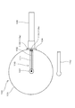
本発明の実施形態にかかる調理容器は、図1に示すようなガスコンロ(ガステーブルコンロ)Aを用いて調理を行う場合に用いられる。
すなわち、このガスコンロ(加熱調理器)Aを構成するガスコンロ本体1の上面は、トッププレート2で覆われている。また、ガスコンロAは、円筒状の外形(この実施形態では外径66mm)を有する左バーナ(コンロバーナ)31および右バーナ(コンロバーナ)32の2口のバーナ(ガスバーナ)を備えており、トッププレート2に形成したバーナ用開口(図示せず)を介して、夫々のバーナの外周に形成された炎孔部33をトッププレート2の上方に突出させている。
<Configuration of a gas stove using a cooking container according to an embodiment of the present invention>
The cooking container according to the embodiment of the present invention is used when cooking is performed using a gas stove (gas table stove) A as shown in FIG.
That is, the top surface of the gas stove
また、図1に示すように、ガスコンロAにおいて左バーナ31および右バーナ32より前方側に位置しているその前面には、使用者が手動にて左バーナ31の点消火操作を行うための左点消火操作部41および使用者が手動にて右バーナ32の点消火操作を行うための右点消火操作部42が設けられている。
この実施形態の加熱調理器においては、上述の左点消火操作部41,42が、加熱量調節指令手段(バーナ操作部)としても機能するように構成されている。
In addition, as shown in FIG. 1, on the front side of the gas stove A located on the front side with respect to the
In the heating cooker of this embodiment, the above-mentioned left point fire extinguishing
また、ガスコンロA内には、左点消火操作部41および右点消火操作部42の操作に基づいて、図4に示すように、ガス供給路8に備えるガスバルブ9の開閉および図示しないイグナイタの発停により左バーナ31および右バーナ32の点消火の制御を行い、また、ガス供給路8からの分岐路8aに備える図示しないステッピングモータ駆動による流量制御弁10の開度調節を行って左バーナ31および右バーナ32に供給されるガス量を調節して左バーナ31および右バーナ32の火力の制御を行う制御部(燃焼制御手段)(本発明における加熱部の加熱力を調節する加熱力調節手段)11を備えている。
In the gas stove A, as shown in FIG. 4 based on the operation of the left point fire extinguishing
また、ガスコンロAはガスグリル部(図示せず)を備えており、ガスコンロAの前面には、ガスグリル部の前面に備える扉(図示せず)を開閉するためのグリル取っ手44およびガスグリル部の点消火操作を行うためのグリル点消火操作部43を備えおり、ガスグリル部における調理に伴う排気はトッププレート2の後方に設けたグリル排気口45から排出されるように構成されている。
In addition, the gas stove A is equipped with a gas grill (not shown), and on the front of the gas stove A, a
トッププレート2上における左バーナ31および右バーナ32夫々の炎孔部33の周囲には、コンロバーナ(左バーナ31、右バーナ32)によって加熱される調理容器100(図3参照)を載置する五徳50が配置されている(図1)。
The cooking vessel 100 (see FIG. 3) heated by the stove burner (the
五徳50は、調理容器100(図3参照)を載置するための五徳爪51を炎孔部33の周囲に複数放射状に配置してあり、夫々の五徳爪51の下端が円環状の五徳リング52で結合されて、トッププレート2上に載置されている。
In
また、左バーナ31および右バーナ32は、調理容器100の底面と接して、調理容器(被加熱物)100の温度を検出する第1温度検出手段72を備えている。
In addition, the
第1温度検出手段72は、図示しないスプリングにより上方向に付勢されており、五徳50に調理容器100を載置することで、調理容器100の底面に第1温度検出手段72の上端が当接しながら第1温度検出手段72が図示しないスプリングによる付勢力に抗して降下する。
The first temperature detection means 72 is biased upward by a spring (not shown), and by placing the
また、このガスコンロAは、第1温度検出手段72の降下を検出するスイッチ(図示せず)を備え、五徳50に調理容器100が載置されたことを検出することができるように構成されている。つまり、このガスコンロAは、は、調理容器100の存否を検出する、調理容器存否検出手段(図示せず)を備えている。
Further, the gas stove A is provided with a switch (not shown) for detecting the drop of the first
なお、ガスコンロAは左バーナ31および右バーナ32の2つのコンロバーナを備えるものであるが、左バーナ31および右バーナ32ともに本発明の実施形態としては同様の形態を有するものであるので、以下、左バーナ31について詳しく説明する。
In addition, although the gas stove A is provided with two stove burners, the
ガスコンロAが備える左バーナ31について詳細に説明すると、図1に示すように、左バーナ(コンロバーナ)31と、手動にて操作される左点消火操作部41と、使用者による左点消火操作部41の操作によって左点消火操作部41から出力される指令に基づいて左バーナ31の点消火および火力の制御を行う制御部(燃焼制御手段)11(図4参照)を備えている。なお、点消火操作部が、後述する点消火指令手段を構成する。
The
上述の制御部(燃焼制御手段)11は、第1温度検出手段72の検出情報に基づいて左バーナ31の作動を制御するように構成されている。
The control unit (combustion control means) 11 described above is configured to control the operation of the
制御部11は、左点消火操作部41の操作によって左点消火操作部41から出力される設定火力の指令に基づいて左バーナ31の火力を手動設定火力に設定する制御を行う。
The
また、制御部11は、左バーナ31の燃焼中において第1温度検出手段72が検出する温度を、温度設定部(図示せず)にて設定された設定温度(例えば、180℃)に維持するように、左バーナ31の火力を制御する自動温度調節制御を実行する。
Further, the
<ロータリーエンコーダ(加熱量調節指令手段)>
この実施形態の、加熱量調節指令手段(バーナ操作部)としても機能する点消火操作部41にはロータリーエンコーダが用いられており、ロータリーエンコーダ(火力調節指令手段)41は、図2に示すように、正方向(時計回り)への回転操作に伴って2相のパルス信号のうちの一方(A相)のパルス信号が他方(B相)のパルス信号より位相が進み、逆方向(反時計回り)への回転操作に伴って他方(B相)のパルス信号が一方(A相)のパルス信号より位相が進む状態で、ロータリーエンコーダの回転操作に伴って互いに異なる位相の2相のパルス信号を出力するように構成されている。
<Rotary encoder (heating amount adjustment command means)>
A rotary encoder is used for the point fire extinguishing
また、この実施形態では、ロータリーエンコーダは、一周(360度)回転させたときに、A相およびB相夫々において24パルスを発生するように構成されている。 Also, in this embodiment, the rotary encoder is configured to generate 24 pulses in each of the A-phase and B-phase when it makes one rotation (360 degrees).
この実施形態では、制御部において、A相から出力されるパルスの立ち上がりエッジstを検出する回数によって、ロータリーエンコーダの回転操作量を判別する。 In this embodiment, the control unit determines the amount of rotational operation of the rotary encoder based on the number of times that the rising edge st of the pulse output from the A phase is detected.
たとえば、制御部は、A相から出力されるパルスの立ち上がりエッジstをn回検出したときには、標準バーナの火力をn段変更する指令がなされたと判断する。 For example, when detecting the rising edge st of the pulse output from the A phase n times, the control unit determines that a command to change the thermal power of the standard burner by n stages has been issued.
また、この実施形態では、制御部において、A相から出力されるパルスの立ち上がりエッジstを検出したときのB相が高レベルであるか低レベルであるかを検出し、その状態によって、ロータリーエンコーダが正方向(時計回り)に回転操作された標準バーナの火力増加指令であるのか、ロータリーエンコーダが逆方向(反時計回り)に回転操作された標準バーナの火力増加指令であるのかを判断する。 In this embodiment, the control unit detects whether the B phase is high or low when the rising edge st of the pulse output from the A phase is detected, and the rotary encoder is selected depending on the state. It is determined whether it is a heating power increase command of the standard burner rotated in the forward direction (clockwise) or a heating power increase command of the standard burner rotated in the reverse direction (counterclockwise).
さらに具体的には、制御部は、図2(a)に示すように、A相から出力されるパルスの立ち上がりエッジstを検出したときのB相が低レベルであるときには、ロータリーエンコーダが正方向(時計回り)に回転操作された標準バーナの火力増加指令であると判断し、図2(b)に示すように、A相から出力されるパルスの立ち上がりエッジstを検出したときのB相が高レベルであるときには、ロータリーエンコーダが逆方向(反時計回り)に回転操作された標準バーナの火力減少指令であると判断する。 More specifically, as shown in FIG. 2A, when the B phase at the time of detecting the rising edge st of the pulse output from the A phase is at a low level, the control unit controls the rotary encoder in the positive direction. It is determined that it is the thermal power increase command of the standard burner rotated (clockwise), and as shown in FIG. 2 (b), the B phase when the rising edge st of the pulse output from the A phase is detected When it is at the high level, it is judged that the rotary encoder is the power reduction command of the standard burner rotated in the reverse direction (counterclockwise).
上述のように、この実施形態のガスコンロAは、調理容器100を加熱する複数のコンロバーナ31,32と、コンロバーナ31,32の火力を調節する火力調節手段(流量制御弁)10と、火力調節指令手段としても機能する点消火指令手段41,42と、調理容器100の底面に当接してこの調理容器100の底面の温度を検出する第1温度検出手段72と、コンロバーナ31,32の燃焼を制御する燃焼制御手段11とを備え、燃焼制御手段11が、点消火指令手段41,42の前記燃焼開始指令に基づいて、コンロバーナ31,32の燃焼を開始し、かつ、燃焼停止指令に基づいて、コンロバーナ31,32の燃焼を停止させる燃焼制御を実行するとともに、燃焼制御手段11が、第1温度検出手段72による検出温度に基づいてコンロバーナ31,32の火力を調節するように構成されている。
As described above, the gas stove A of this embodiment includes a plurality of
<本発明の実施形態にかかる調理容器の構成>
本発明の一実施形態にかかる温度検出部を備える調理容器は、上で説明したような加熱調理器A(図1、図2、図4など参照)とともに用いられる。
<Configuration of Cooking Container according to Embodiment of the Present Invention>
The cooking container provided with the temperature detection part concerning one Embodiment of this invention is used with heating cooker A (refer FIG.1, FIG.2, FIG.4 etc.) which was demonstrated above.
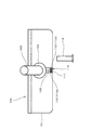
そして、この実施形態の温度検出部を備えた調理容器100は、図3に示すように、第1金属(たとえば銅)からなる調理容器本体101と、温度検出部として調理容器本体101に組み込まれる組込み温度検出部120と、組込み温度検出部120による検出温度を、上述のガスコンロ(加熱調理器)Aの加熱力調節手段(燃焼制御手段11)に送信する組込み温度送信部(RFモジュール)103とを備えている(図3)。
And the
なお、図5は、組込み温度送信部(RFモジュール)103から送信されるデータ(タグ情報)の種類を示す図である。
すなわち、組込み温度送信部(RFモジュール)103から送信されるデータ(タグ情報)は、図5では「g」に示されている組込み温度検出手段の検出温度のみではなく、「g:組込み温度検出手段の検出温度」以外にも、
a:鍋ID
b:メーカ
c:鍋の品番
d:種類(フライパン、雪平、両手鍋(浅い)、両手鍋(深い)、やかん、土鍋……など)
e:シリアル番号
f:材質、厚み、深さ、容積など
のデータが送信されるように構成されており、これらのデータが適宜用いられることで、一層的確な自動調理を行うことができるように構成されている。
FIG. 5 is a diagram showing types of data (tag information) transmitted from the built-in temperature transmission unit (RF module) 103.
That is, the data (tag information) transmitted from the built-in temperature transmission unit (RF module) 103 is not only the detection temperature of the built-in temperature detection means shown by "g" in FIG. In addition to the "detected temperature of means"
a: Pan ID
b: Maker c: Part number of pot d: Type (frying pan, snow flat, both hands pot (shallow), both hands pot (deep), kettle, clay pot ... etc.)
e: Serial number f: Data such as material, thickness, depth, volume, etc. are configured to be transmitted. By using these data as appropriate, automatic cooking can be performed more accurately. It is configured.
この実施形態にかかる調理容器100において、組込み温度検出部120は、調理容器本体101を構成する第1金属(例えば銅)と、この第1金属とは種類の異なる第2金属(例えばコンスタンタン)からなる第2金属体102の一端とが接合された接合部107を備えた熱電対から構成されている(図3、図6、図9参照)。
In the
また、組込み温度送信部(RFモジュール)103は、取っ手固定具104によって調理容器本体101に固定される取っ手105内に装着されている。
なお、取っ手固定具104と調理容器本体101との間、および、取っ手105と取っ手固定具104との間は、図示しないシール材により水密的にシールされており、組込み温度送信部(RFモジュール)103への水などの浸入を防止することができるように構成されている。
Further, the built-in temperature transmission unit (RF module) 103 is mounted in the
In addition, between the
また、調理容器100は、調理容器本体101の底部に形成され下方に開口111を有する収容凹部110(図6、図7、図8、図9、図10、図11)と、開口111を塞ぐカバー体112(図3、図6、図7、図8、図9、図11、図12参照)とを備えている。
In addition, the
そして、上述の収容凹部110は、調理容器本体101の底面から側面に回り込むように形成されており、収容凹部110には、第2金属体102が配設されている。なお、第2金属体102は、収容凹部110内に配設された絶縁体113(第1絶縁体113a、第2絶縁体113b)(図3、図6、図7、図8、図9、図10、図11参照)によって調理容器本体110およびカバー体112と電気的に絶縁されて、収容凹部110に収容されている。
なお、カバー体112は、図12(a),(b),(c)に示すように、調理容器本体101の底面から側面に回り込むように形成された収容凹部110の開口111を塞ぐことができるようにL字状に形成されているとともに、熱電対の接合部107が収容された領域を覆う部分は部分円状に形成されている。
And the above-mentioned
In addition, the
また、第2金属体102の接合部107を構成する一端に対する他端(後述の第2中継部122)が、第2リード線132によって、組込み温度送信部(RFモジュール)103に電気的に接続されている(図3)。
Further, the other end (
また、第1金属から構成された調理容器本体101の、調理容器本体101の外周部に位置する第1中継部121が、絶縁被覆された第1リード線131によって、組込み温度送信部(RFモジュール)103に電気的に接続されている(図3)。
In addition, the
この実施形態の、温度検出部を備えた調理容器100は、上述のように構成されており、調理容器本体101を構成する第1金属(銅)と、この第1金属(銅)とは異なる種類の第2金属(コンスタンタン)からなる第2金属体102の一端とを接合した接合部107を備える熱電対で、組込み温度検出部120を構成しているので、組込み温度検出部120による検出温度と調理容器100に収納されている被調理物の温度との間に生じるずれを小さくすることができる。すなわち、調理容器100に収納されている被調理物の温度を精度よく検出することができる。
The
また、この実施形態の調理容器100においては、上述のように、第2金属体102の他端である第2中継部122を、組込み温度送信部(RFモジュール)103に電気的に接続するのに絶縁被覆された第2リード線132を用いるとともに、第1金属から構成された調理容器本体101の、調理容器本体101の外周部に位置する第1中継部121を、組込み温度送信部(RFモジュール)103に電気的に接続するのに、絶縁被覆された第1リード線131を用いている。
Moreover, in the
このように、第1リード線131および第2リード線132として絶縁被覆されたリード線を用いることにより、収容凹部110の外において、1リード線131と第2リード線132とが電気的に短絡することを確実に防止することができるため、温度検出部による検出温度(起電力)が、組込み温度送信部(RFモジュール)103に適正に入力されることになる。
As described above, by using the lead wires insulated and coated as the
さらに、この実施形態の調理容器100においては、第1リード線131が調理容器本体101と同じ種類の金属(銅)で構成されているため、第1中継部121の温度と組込み温度送信部(RFモジュール)103の温度とが異なるときにも、温度検出部による検出温度(起電力)が、組込み温度送信部(RFモジュール)103に適正に入力される。
Furthermore, in the
また、第2リード線132も、第2金属体102と同じ種類の金属(コンスタンタン)で構成されている。したがって、第2中継部122の温度と組込み温度送信部(RFモジュール)103の温度とが異なる場合にも、温度検出部による検出温度(起電力)が組込み温度送信部(RFモジュール)103に適正に入力されることになり、信頼性が向上する。
The
なお、第1リード線131を、調理容器本体101を構成する第1金属(銅)と異なる種類の金属(銅以外の金属)で,また、第2リード線132を、第2金属体102を構成する第2金属(コンスタンタン)と異なる種類の金属(コンスタンタン以外の金属)で構成することも可能である。
Incidentally, the
また、この実施形態にかかる調理容器100においては、絶縁体113が、第1絶縁体113aと第2絶縁体113bから形成されており、第1絶縁体113aの一部が、開口111がカバー体112によって塞がれた状態であるカバー体装着状態(図10参照)において、第2金属体102が第1絶縁体113aと第2絶縁体113bとの間に位置するようにガイドするガイド部133を構成している(図10、図11参照)。
Moreover, in the
このように、絶縁体113にガイド部133を設けた構成とすることにより、開口111がカバー体112によって塞がれた状態において、第2金属体102と、カバー体112および調理容器本体101の間の電気的絶縁を確実に維持することが可能になり、組込み温度検出部により検出された検出温度(起電力)が組込み温度送信部(RFモジュール)103に一層適正に入力されることになり、信頼性を向上させることができる。
As described above, by providing the
また、調理容器100は、カバー体112が装着されたカバー体装着状態(図10)において、カバー体112が収容凹部110側に移動しないようにするための移動規制部141を備えている。移動規制部141は、収容凹部110の内周に設けられた段差部141aから構成されている。
Moreover, the
このように、移動規制部141を備えることにより、カバー体装着状態において、カバー体112を絶縁体13に向かって付勢するような外力などが作用した場合にも、カバー体112が収容凹部110内の絶縁体113側に移動して絶縁体113(113a,113b)が破損し、電気的絶縁が劣化することを防止することが可能になり、信頼性の高い温度検出部を備えた調理容器100を実現することができる。
As described above, by providing the
また、調理容器100は、カバー体112が装着されたカバー体装着状態(図10)において、カバー体112が収容凹部110から離脱しないようにするための離脱規制部142を備えている。
Moreover, the
この離脱規制部142は、図10に示すように、カバー体112の外周部に、当該外周部を周回するように設けられた凸条143と、収容凹部110の内周部(より具体的には,収容凹部110の一部である、カバー部材112が収容される領域の内周部)に、当該内周部を周回するように設けられた、カバー体装着状態においてカバー体112の凸条143が嵌入する凹条144とによって形成されている。
As shown in FIG. 10, the
なお、特に図示しないが、カバー体112の外周部に、当該外周部を周回するように凹条を設け、収容凹部110の内周部に、当該内周部を周回する凸条を設けることによっても離脱規制部を構成することが可能である。
Although not shown in the drawings, the outer circumferential portion of the
上述のように、離脱規制部142を備えることにより、カバー体装着状態において、カバー体112に外力などが作用したり、調理容器100の温度が変化して調理容器100自本体やカバー体112が収縮したりした場合に、カバー体112が収容凹部110から離脱して第2金属体102が露出することが抑制、防止して、信頼性の高い組込み温度検出部を備えた調理容器100を実現することができる。
As described above, by providing the
また、この実施形態にかかる調理容器100においては、カバー体112に対して、図11に示すように、その初期形態として、カバー体112が備える凸条143と、調理容器本体101の収容凹部110とが干渉しない状態となるように、湾曲部112aを有する初期形態が与えられている。
Further, in the
そして、このような初期形態を有するカバー体112を、収容凹部110を覆う位置に置いた後、プレス加工などにより、湾曲部112aが平坦になるように塑性変形させ、カバー体112の外周部の凸条143を,収容凹部110の内周部の凹条144に嵌入させて、カバー体112が,収容凹部110に装着されたカバー体装着状態が得られるように構成されている。
Then, after the
上記構成とすることにより、湾曲部112aを有する初期形態のカバー体112を、収容凹部110を覆うように配置し、その湾曲部112aが平坦になるように塑性変形させるだけで、容易かつ確実に、カバー体112により,収容凹部110が封止された状態であるカバー体装着状態とすることが可能になる。
With the above configuration, the
なお、カバー体112をプレス加工などにより押圧して、湾曲部112aが平坦になるように塑性変形させる際に、カバー体112の端縁の収容凹部110の底部側への移動(絶縁体113、第2金属体102を押圧する方向への移動)が移動規制部141によって規制されるので、湾曲部112aが平坦になるように塑性変形させるのに好都合である。
When the
また、カバー体112の外周部に、外周部を周回するように凹条を設け、収容凹部110の内周部に、内周部を周回する凸条を設けることによっても離脱規制部を構成した場合にも、湾曲部112aを有する初期形態のカバー体112を、収容凹部110を覆うように配置し、その湾曲部112aが平坦になるように塑性変形させるだけで、カバー体112の凹部に,収容凹部110の凸部が嵌入して、カバー体112により,収容凹部110が封止された状態であるカバー体装着状態とすることができる。
Further, a recess is provided on the outer peripheral portion of the
また、この場合も、カバー体112の湾曲部112aが平坦になるように塑性変形させる際に、カバー体112の端縁の収容凹部110の底部側への移動(第2金属体102を押圧する方向への移動)が移動規制部141によって規制されるので。湾曲部112aが平坦になるように塑性変形させるのに好都合である。
Also in this case, when plastic deformation is performed so that the
なお、この実施形態の調理容器100においては、カバー体112の湾曲部112aが平坦になるように塑性変形させることで、外周部に凹部または凸部を備えたカバー体112と、調理容器本体101の,内周部に凹部または凸部を備えた収容凹部110とを密着させて、収容凹部110を水密状態にすることができる(図10参照)。その結果、調理容器本体101の収容凹部110に水などが浸入することを防止することが可能で、信頼性の高い、温度検出部を備えた調理容器を得ることが可能になる。
In addition, in the
因みに、湾曲部が平坦になるように塑性変形することで、カバー体と調理容器本体とが水密的に密着するような構成を備えていない場合には、カバー体と調理容器本体との間から収容凹部に水が浸入しないように、シール部材を用いてシールを施す必要があるが、このシール部材は相当の耐熱性(調理容器本体およびカバー体と同程度の耐熱性)が必要であるのに対し、上記実施形態の調理容器では、このようなシール部材が不要であり、シール部材の耐熱性の経年劣化などに起因する収容凹部への水の浸入による性能の劣化が抑制される。 By the way, if the cover body and the cooking vessel main body do not have a configuration in which the cover body and the cooking vessel main body adhere in a watertight manner by plastic deformation so that the curved portion becomes flat, from between the cover body and the cooking vessel main body Although it is necessary to seal using a seal member so that water does not infiltrate into the housing recess, this seal member needs to have considerable heat resistance (heat resistance comparable to that of the cooking container main body and cover body) On the other hand, in the cooking container of the said embodiment, such a sealing member is unnecessary and the deterioration of the performance by the penetration of the water to the accommodation recessed part resulting from the heat-resistant deterioration etc. of a sealing member is suppressed.
<変形例>
上述の実施形態では、ガイド部を第1絶縁体に設けるようにしているが、第2絶縁体にガイド部を設けてもよく、また、場合によっては第1絶縁体と第2絶縁体の両方にガイド部を設けるように構成することも可能である。
<Modification>
In the above embodiment, the guide portion is provided in the first insulator, but the guide portion may be provided in the second insulator, and in some cases, both the first insulator and the second insulator may be provided. It is also possible to provide a guide section at
また、上述の実施形態では、第1金属を銅とし、第2金属をコンスタンタンとしたが、第1金属および第2金属の種類に特別の制約はなく、第1金属と第2金属とが異なる種類の金属であれば、第1金属および第2金属を銅やコンスタンタン以外の金属としてもよい。 In the above embodiment, although the first metal is copper and the second metal is constantan, the types of the first metal and the second metal are not particularly limited, and the first metal and the second metal are different. If it is a kind of metal, the first metal and the second metal may be copper or metals other than constantan.
本発明はさらにその他の点においても上記実施形態に限定されるものではなく、本発明の範囲内において種々の変形を加えることが可能である。 The present invention is not limited to the above embodiment in other points, and various modifications can be made within the scope of the present invention.
1 ガスコンロ本体
2 トッププレート
8 ガス供給路
9 ガスバルブ
8a 分岐路8a
10 流量制御弁
11 制御部(燃焼制御手段)
31 左バーナ(コンロバーナ)
32 右バーナ(コンロバーナ)
33 炎孔部
41 左点消火操作部
42 右点消火操作部
43 グリル点消火操作部
44 グリル取っ手
45 グリル排気口
50 五徳
51 五徳爪
52 五徳リング
72 第1温度検出手段
100 調理容器
101 調理容器本体
102 第2金属体
103 組込み温度送信部(RFモジュール)
104 取っ手固定具
105 取っ手
107 接合部
110 収容凹部
111 開口
112 カバー体
112a 湾曲部
113 絶縁体
113a 第1絶縁体
113b 第2絶縁体
120 組込み温度検出部
121 第1中継部
122 第2中継部
131 第1リード線
132 第2リード線
133 ガイド部
141 移動規制部
141a 段差部
142 離脱規制部
143 カバー体の外周部に設けられた凸条
144 収容凹部の内周部に設けられた凹条
A ガスコンロ
1 gas stove main body 2
10
31 Left burner (stove burner)
32 Right burner (stove burner)
33
DESCRIPTION OF
Claims (6)
第1金属からなる調理容器本体と、
前記調理容器本体に組み込まれた組込み温度検出部であって、前記調理容器本体である前記第1金属と、前記第1金属とは種類の異なる第2金属からなる第2金属体の一端とを接合することにより形成された熱電対からなる組込み温度検出部と、
前記組込み温度検出部による検出温度を前記加熱調理器の加熱力調節手段に送信する組込み温度送信部と、
前記調理容器本体の底部に形成され、下方に開口を有する、前記第2金属体を収容する収容凹部と、
前記収容凹部の前記開口を塞ぐためのカバー体と、
前記組込み温度送信部と前記調理容器本体の外周部に位置する第1中継部とを電気的に接続する第1リード線と
を備えるとともに、
前記第2金属体が、絶縁体によって前記調理容器本体および前記カバー体と電気的に絶縁された状態で、前記収容凹部に収容され、かつ、
前記第2金属体の前記一端に対する他端が、前記組込み温度送信部と電気的に接続されているとともに、
前記絶縁体が、第1絶縁体と第2絶縁体とからなり、
前記第1絶縁体と前記第2絶縁体の少なくとも一方は、前記開口が前記カバー体によって塞がれた状態であるカバー体装着状態において、前記第2金属体が前記第1絶縁体と前記第2絶縁体との間に位置するようにガイドするガイド部を備えており、
前記第2金属体は前記カバー体装着状態において、前記ガイド部材によりガイドされて、前記第1絶縁体と前記第2絶縁体との間に位置していること
を特徴とする、温度検出部を備えた調理容器。 A cooking vessel provided with a temperature detection unit, which is used together with a heating cooker including a heating unit for heating a cooking vessel and heating power adjusting means for adjusting the heating power of the heating unit,
A cooking vessel body made of a first metal;
The built-in temperature detection unit incorporated in the cooking vessel main body, the first metal being the cooking vessel main body, and one end of a second metal body made of a second metal different in type from the first metal. A built-in temperature detection unit comprising a thermocouple formed by bonding;
A built-in temperature transmission unit that transmits the temperature detected by the built-in temperature detection unit to the heating power adjustment means of the heating cooker ;
An accommodation recess formed at the bottom of the cooking vessel main body and having an opening at the lower side, which accommodates the second metal body;
A cover body for closing the opening of the housing recess;
And a first lead wire electrically connecting the built-in temperature transmission unit and a first relay unit positioned on an outer peripheral portion of the cooking vessel body.
The second metal body is accommodated in the accommodation recess in a state where the second metal body is electrically insulated from the cooking vessel main body and the cover body by an insulator;
The other end of the second metal body to the one end is electrically connected to the built-in temperature transmitter .
The insulator comprises a first insulator and a second insulator,
In a cover mounted state in which at least one of the first insulator and the second insulator is in a state where the opening is closed by the cover, the second metal body is the first insulator and the first insulator. 2) It has a guide that guides it to be located between the two insulators,
The temperature detection unit is characterized in that the second metal body is guided by the guide member in the mounted state of the cover body and positioned between the first insulator and the second insulator. Cooking container equipped.
前記調理容器本体の前記収容凹部の内周部に、前記内周部を周回し、前記カバー体装着状態で前記カバー体の前記凸条が嵌入する凹条が設けられているか、または、
(b)前記調理容器本体の前記収容凹部の内周部に、前記内周部を周回する凸条が設けられ、
前記カバー体の外周部に、前記外周部を周回し、前記カバー体装着状態で前記調理容器本体の前記凸条が嵌入する凹条が設けられていること
を特徴とする請求項3記載の、温度検出部を備えた調理容器。 (A) The outer peripheral part of the said cover body is provided with the convex streak which encircles the said outer peripheral part,
The inner peripheral portion of the accommodation recess of the cooking container main body is provided with a concave groove which encircles the inner peripheral portion and into which the convex stripe of the cover body is fitted in the cover body mounted state, or
(B) The inner peripheral part of the said accommodation recessed part of the said cooking container main body is provided with the convex streak which goes around the said inner peripheral part,
The outer peripheral portion of the cover member, the outer peripheral portion orbiting of claim 3, wherein the concave stripes the ridges of the cooking container body with the cover member mounted state is fitted is provided, A cooking vessel equipped with a temperature detection unit.
Priority Applications (1)
| Application Number | Priority Date | Filing Date | Title |
|---|---|---|---|
| JP2015108206A JP6525731B2 (en) | 2015-05-28 | 2015-05-28 | Cooking container equipped with a temperature detection unit |
Applications Claiming Priority (1)
| Application Number | Priority Date | Filing Date | Title |
|---|---|---|---|
| JP2015108206A JP6525731B2 (en) | 2015-05-28 | 2015-05-28 | Cooking container equipped with a temperature detection unit |
Publications (2)
| Publication Number | Publication Date |
|---|---|
| JP2016220786A JP2016220786A (en) | 2016-12-28 |
| JP6525731B2 true JP6525731B2 (en) | 2019-06-05 |
Family
ID=57746179
Family Applications (1)
| Application Number | Title | Priority Date | Filing Date |
|---|---|---|---|
| JP2015108206A Active JP6525731B2 (en) | 2015-05-28 | 2015-05-28 | Cooking container equipped with a temperature detection unit |
Country Status (1)
| Country | Link |
|---|---|
| JP (1) | JP6525731B2 (en) |
Families Citing this family (2)
| Publication number | Priority date | Publication date | Assignee | Title |
|---|---|---|---|---|
| FR3081307B1 (en) | 2018-05-25 | 2020-05-01 | Seb S.A. | COOKING CONTAINER COMPRISING A SOUND WARNING BIMETALLIC ELEMENT |
| KR20220072375A (en) * | 2020-11-25 | 2022-06-02 | 엘지전자 주식회사 | Electric kettle |
Family Cites Families (3)
| Publication number | Priority date | Publication date | Assignee | Title |
|---|---|---|---|---|
| US5441344A (en) * | 1993-10-22 | 1995-08-15 | Cook, Iii; Walter R. | Temperature measurement and display of a cooking surface |
| US9955529B2 (en) * | 2009-01-06 | 2018-04-24 | Access Business Group International Llc | Smart cookware |
| FR3004631B1 (en) * | 2013-04-18 | 2015-09-18 | Seb Sa | COOKING CONTAINER COMPRISING A TEMPERATURE SENSOR HAVING A FIXING ELEMENT |
-
2015
- 2015-05-28 JP JP2015108206A patent/JP6525731B2/en active Active
Also Published As
| Publication number | Publication date |
|---|---|
| JP2016220786A (en) | 2016-12-28 |
Similar Documents
| Publication | Publication Date | Title |
|---|---|---|
| CN106943000B (en) | A kind of temperature-sensitive cookware can be used for kinds of stove | |
| US7488920B2 (en) | Radiant heater in a cooking hob with a thermal switch | |
| JP6525731B2 (en) | Cooking container equipped with a temperature detection unit | |
| JPH01219428A (en) | Temperature sensor assembly for automatic surface device | |
| JP4193213B2 (en) | rice cooker | |
| JP4448400B2 (en) | Gas stove with thermal power control function | |
| CN103565304B (en) | Food process pot | |
| EP2708816A2 (en) | A touch-sensitive gas control system and a cam gas tap for domestic cooking appliances | |
| JP2008215741A (en) | Range hood | |
| JP5436529B2 (en) | Gas stove | |
| JP6512890B2 (en) | Gas stove | |
| JP5735937B2 (en) | Electric diaphragm valve | |
| JP2014032001A (en) | Gas cooking stove | |
| JP2021055908A (en) | Gas cooking stove system | |
| JP4451260B2 (en) | Cooker temperature detection device | |
| JP4146390B2 (en) | Cooker | |
| CN214172220U (en) | Burner and cooking utensil | |
| CN109423877A (en) | Flatiron including resistance and for cutting off the fuse to resistance power supply | |
| CN110248578A (en) | Small household appliance | |
| FR2569932A1 (en) | TEMPERATURE CONTROL DEVICE FOR A COOKING OVEN | |
| JPH0735906B2 (en) | Gas cooker with temperature sensor | |
| JPH061090Y2 (en) | Cooker heat and temperature control device | |
| JP7446083B2 (en) | Heating cooker and heating cooking system | |
| EP1865752B1 (en) | Radiant heater mounted with a thermal switch in a cooking hob | |
| JP4202155B2 (en) | Operation switch |
Legal Events
| Date | Code | Title | Description |
|---|---|---|---|
| A621 | Written request for application examination |
Free format text: JAPANESE INTERMEDIATE CODE: A621 Effective date: 20180416 |
|
| A977 | Report on retrieval |
Free format text: JAPANESE INTERMEDIATE CODE: A971007 Effective date: 20181207 |
|
| A131 | Notification of reasons for refusal |
Free format text: JAPANESE INTERMEDIATE CODE: A131 Effective date: 20181218 |
|
| A521 | Request for written amendment filed |
Free format text: JAPANESE INTERMEDIATE CODE: A523 Effective date: 20190212 |
|
| TRDD | Decision of grant or rejection written | ||
| A01 | Written decision to grant a patent or to grant a registration (utility model) |
Free format text: JAPANESE INTERMEDIATE CODE: A01 Effective date: 20190423 |
|
| A61 | First payment of annual fees (during grant procedure) |
Free format text: JAPANESE INTERMEDIATE CODE: A61 Effective date: 20190507 |
|
| R150 | Certificate of patent or registration of utility model |
Ref document number: 6525731 Country of ref document: JP Free format text: JAPANESE INTERMEDIATE CODE: R150 |
|
| R250 | Receipt of annual fees |
Free format text: JAPANESE INTERMEDIATE CODE: R250 |
|
| R250 | Receipt of annual fees |
Free format text: JAPANESE INTERMEDIATE CODE: R250 |