JP6525428B2 - Home door device - Google Patents
Home door device Download PDFInfo
- Publication number
- JP6525428B2 JP6525428B2 JP2013102211A JP2013102211A JP6525428B2 JP 6525428 B2 JP6525428 B2 JP 6525428B2 JP 2013102211 A JP2013102211 A JP 2013102211A JP 2013102211 A JP2013102211 A JP 2013102211A JP 6525428 B2 JP6525428 B2 JP 6525428B2
- Authority
- JP
- Japan
- Prior art keywords
- door
- home
- train
- passenger
- open
- Prior art date
- Legal status (The legal status is an assumption and is not a legal conclusion. Google has not performed a legal analysis and makes no representation as to the accuracy of the status listed.)
- Active
Links
Images


Landscapes
- Platform Screen Doors And Railroad Systems (AREA)
Description
本発明はホームドア装置に関し、特に、列車の各車両ドアに対応して乗降用の通路区画を形成し当該乗降用通路区画に存在する旅客等の残留を検知するのに好適なホームドア装置に関するものである。 The present invention relates to a home door apparatus, and more particularly to a home door apparatus suitable for forming a passage section for getting on and off corresponding to each vehicle door of a train and detecting a remaining passenger or the like present in the getting on / off section. It is a thing.
従来のホームドア装置は、通常、左右に開閉する可動式の一対のドア(ホームドア)を有している。この一対のドアの各々は、駅ホーム床面に固定された筐体の戸袋構造部に出し入れ自在に設けられている。ホームドア装置は、駅ホームに入線し停止する列車の各車両ドアの位置に対応して駅ホームのホーム側縁に沿って設置されている。駅ホームに停車した列車において旅客を乗降させるためにすべての車両ドアを開閉するとき、ホームドア装置のドアは、列車運行の制御システムに基づき、車両ドアの開閉動作に同期して開閉するように制御される。ホームドア装置のドアは、列車の車両ドアが開くときに同期して開き、旅客の乗降が終わり当該車両ドアを閉じるときに同期して閉じる。ホームドア装置のドアが開く(開放する)と乗降通路(乗降口)が形成され、当該ドアが閉じる(閉鎖する)と乗降通路(乗降口)がなくなる。車両ドアとホームドア装置のドアが閉じた時には、車両ドアとホームドア装置のドアの間のスペースに旅客が残留しないようにすることが、安全な列車運行上、重要である。当該スペースに旅客がいる場合には、列車は発車することはできない。そのため、従来では、図8に示すように、停車した列車100の車両ドア101とホームドア装置102のドア103との間のスペース104に残留物が存在しないことを確認するための光電センサ105等が配置される。光電センサ105等において、発光器105aと受光器105bとから構成される。発光器105aから出射された光線106は受光器105bに受光される。スペース104に旅客がいる場合には、光線106が遮られるので、これにより旅客の残留の有無を検知することができる。光線106の例としては赤外線である。
A conventional home door apparatus usually has a pair of movable doors (home doors) that open and close left and right. Each of the pair of doors is provided so as to be freely inserted into and removed from the door case structure portion of the housing fixed to the station home floor surface. The home door device is installed along the home side edge of the station home corresponding to the position of each vehicle door of the train entering and stopping at the station home. When opening and closing all the vehicle doors to get on and off the passenger in the train stopped at the station home, the door of the home door device opens and closes in synchronization with the opening and closing operation of the vehicle door based on the control system of train operation. It is controlled. The door of the home door system is synchronously opened when the train's vehicle door is opened and closed synchronously when the passenger's getting on and off is finished and the vehicle door is closed. When the door of the home door apparatus is opened (opened), a passenger passage (airport) is formed, and when the door is closed (closed), the passenger passage (airport) is eliminated. When the vehicle door and the door of the home door system are closed, it is important for safe train operation that no passengers remain in the space between the vehicle door and the door of the home door system. If there is a passenger in the space, the train can not be launched. Therefore, conventionally, as shown in FIG. 8,
また本願発明に関連する従来の文献として、ホームドア装置を開示する特許文献1が存在する。特許文献1に開示されるホームドア装置は、視覚障害者等が誤ってホームドア装置の戸袋(筐体部分)と車両との間に入り込んで取り残されるを防止するため、戸袋の車両側の壁面の部分にガイドを設けるように構成している。当該ガイドは、板状部材であり、垂直方向に備えられると共に、乗降口(乗降通路)の開放時には戸袋に直角でその先端が車両側に向かい、乗降口(乗降通路)の閉鎖時には戸袋に対して平行になるように、回転する機構部を介して設けられている。ガイドの回転動作は、ホームドア装置の開閉ドアの開閉動作に連動する連動機構によって行われる。こうして、ホームドア装置の乗降口が開放される時には、ガイドが戸袋と車両との間のスペースが塞がれる。
Further, as a conventional document related to the present invention, there is
スペース104に残留した旅客等を検知するための光電センサ105等を利用した検知装置の構成は、赤外線106等を利用するために、太陽光、雨、雪等の影響を受け、屋外に設置されたホームドア装置に適用することは困難であるという問題が提起される。また電気的な検知装置の構成や、検知装置の検知信号を処理する手段を設けることが必要となり、構成が複雑になり、コストがかかるという問題も提起する。
他方、引用文献1に開示されたホームドア装置によれば、ドアを格納する戸袋構造を有した筐体の車両側壁面を利用してガイドを設け、乗降口が開放されるときガイドを回転させることにより進入阻止部材として機能させ、視覚障害者等が筐体と車両との間のスペースに入り込むのを防止するようにしている。しかしながら、車両ドアとホームドア装置のドアが閉じたときには車両ドアと当該ドアとの間のスペースに旅客が残留するのを検知することはできない。
The configuration of the detection device using the
On the other hand, according to the home door device disclosed in
本発明の目的は、上記の課題に鑑み、停車した列車の各車両ドアに対応して乗降通路を形成するよう配置された開閉ドアを備えるホームドア装置で、開閉ドアの閉動作時に乗降通路等に存在する旅客等を確実に検出し旅客等の残留を防止することができ、太陽光等の天気等の影響を受けることなく確実に検知でき、屋外にも設置することができ、かつ簡素な構成で安価なコストで設置することができるようにしたホームドア装置を提供することにある。 An object of the present invention is, in view of the above problems, a home door apparatus provided with an open / close door arranged to form an entrance / exit passage corresponding to each vehicle door of a stopped train, the access passage etc. when closing the open / close door It is possible to reliably detect the passenger etc. who are present in the house and prevent the remaining of the passenger etc. It can be detected reliably without being affected by the weather such as sunlight etc. It can be installed outdoors and it is simple An object of the present invention is to provide a home door device which can be installed at a low cost due to its configuration.
本発明に係るホームドア装置は、上記の目的を達成するため、次のように構成される。 The home door apparatus according to the present invention is configured as follows to achieve the above object.
第1のホームドア装置(請求項1に対応)は、駅ホームに停車した列車の各車両ドアに対応して配置された開閉ドアを備えるホームドア装置において、開閉ドアは、その突き合わせ先端部に列車側への延設部を有し、当該列車側への延設部は、開動作時に旅客が移動できる乗降のための3次元的な空間としての乗降通路区画を形成し、かつ閉動作時に乗降通路区画内のいずれかの箇所に残留する物体を接触で検知可能にすることによって構成される。 The first home door apparatus (corresponding to claim 1) is a home door apparatus including an open / close door arranged corresponding to each vehicle door of a train stopped at a station home, wherein the open / close door has a butt end thereof has extended portion to the train side, extending portion to the train side forms the boarding passage section as a three-dimensional space for the passenger which passengers can move during the opening operation, and during the closing operation It is configured by making it possible to detect an object remaining in any place in the boarding section by contact.
上記のホームドア装置では、開閉するドアそのもの形状または構造として当該開閉ドアの突き合わせ先端部に旅客乗降用の通路区画を形成する列車側への延設部を設ける。当該列車側への延設部は、開動作時に開閉ドアの厚みよりも広い旅客が移動できる乗降のための3次元的な空間としての乗降通路区画を形成する。これにより、開閉ドアの閉動作時における当該列車側への延設部と通路区画の残留物との間の接触作用を利用して残留物の存在の有無を検知する。このため、ホームドア装置のドアが閉じるとき、通路区画に残留物が存する場合には接触作用に基づき確実に残留物を検知することができる。さらに物理的な接触作用に基づき残留物を検知するように構成したため、天気条件や自然条件の影響を受けることがない。 In the above-mentioned home door apparatus, an extension to the side of a train is provided as a shape or structure of the door itself to be opened and closed, forming a passage section for passenger entry and exit at the butt end of the open and close door. The extension part to the said train side forms the getting-on / off passage division as a three-dimensional space for getting-on / off in which the passenger wider than the thickness of the opening and closing door can move at the time of opening operation. Thereby, the presence or absence of a residue is detected using the contact action between the extension part to the said train side at the time of closing operation of an opening-and-closing door, and the residue of a passage section. For this reason, when the door of the home door device is closed, if there is any residue in the passage section, the residue can be reliably detected based on the contact action. Furthermore, since it was comprised so that a residue might be detected based on a physical contact action, it does not receive to the influence of weather conditions or natural conditions.
第2のホームドア装置(請求項2に対応)は、上記の構成において、好ましくは、列車側への延設部は別部材として作られ、開閉ドアの突き合わせ先端部に取り付けられることを特徴とする。 The second home door apparatus (corresponding to claim 2) is characterized in that, in the above configuration, preferably the extension to the train side is made as a separate member and attached to the butt tip of the open / close door. Do.
第3のホームドア装置(請求項3に対応)は、上記の構成において、好ましくは、列車側への延設部は、開閉ドアの突き合わせ先端部を列車側に延設して作られた部分であり、開閉ドアと一体化構造として形成されることを特徴とする。 Third home door apparatus (corresponding to claim 3), in the above configuration, preferably, the extending portion, the portion was made to extend the butt tip of the opening and closing door to the train side to the train side It is characterized in that it is formed as an integral structure with the open / close door.
第4のホームドア装置(請求項4に対応)は、上記の構成において、好ましくは、開閉ドアが閉動作したとき、列車側への延設部が乗降通路区画に残留する物体に接触した状態を、開閉ドアを閉動作させるモータに付設された動作量センサと負荷センサの各検知情報量に基づいて検知することを特徴とする。 In the above configuration, in the fourth home door apparatus (corresponding to claim 4), preferably, when the open / close door is closed , the extension portion to the train side contacts an object remaining in the entrance / exit passage section Is detected based on the amount of information detected by an operation amount sensor and a load sensor attached to a motor for closing the open / close door.
第5のホームドア装置(請求項5に対応)は、上記の構成において、好ましくは、列車側への延設部の突き合わせ先端部の表面に触覚センサを設けたことを特徴とする。 The fifth home door apparatus (corresponding to claim 5) is characterized in that, in the above configuration, a tactile sensor is provided on the surface of the butt tip of the extension part extending to the train side .
本発明によれば、駅ホームに入線し停止した列車の各車両ドアに対応して乗降通路を形成するよう配置された開閉ドアを備えるホームドア装置において、開閉ドアの形状または構造として当該開閉ドアの突き合わせ先端部に旅客が移動できる乗降のための乗降通路区画を形成する列車側への延設部を設けるようにしたため、通路区画における旅客等の残留物を通路形成との接触作用を利用して検知することができ、開閉ドアの閉動作時に乗降通路等に存在する旅客等を確実に検出し旅客等の残留を防止することができ、太陽光等の天気等の影響を受けることなく確実に検知でき、屋外にも設置することができ、かつ簡素な構成で安価なコストで設置することができるという効果が発揮される。 According to the present invention, in a home door apparatus provided with an open / close door arranged to form an entrance / exit passage corresponding to each vehicle door of a train entering and stopping at a station home, the open / close door as a shape or structure of the open / close door Since the extension to the side of the train that forms the boarding passage section for getting on and off where passengers can move is provided at the butt tip of the car , residues of passengers etc. in the passage section are utilized by making contact with the passage formation. It is possible to reliably detect the passenger etc. present in the access passage etc. at the time of closing operation of the open / close door and prevent the passenger etc. from remaining, surely without being affected by the weather such as sunlight etc. Thus, the effect of being able to be installed outdoors can be achieved, and it can be installed at a low cost with a simple configuration.
以下に、本発明の好適な実施形態(実施例)を添付図面に基づいて説明する。 Hereinafter, preferred embodiments (examples) of the present invention will be described based on the attached drawings.
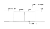
図1と図2を参照して本実施形態に係るホームドア装置の基本的な構成を説明する。ホームドア装置10では、駅ホーム11の縁に沿って所要の間隔をあけて2つのドア筐体12A,12Bが設置されている。2つのドア筐体12A,12Bは、ホーム床面に固定され、それぞれ内部にドア(ホームドア)13A,13Bを収納する戸袋構造を有し、かつドア13A,13Bを移動支持するガイド機構部と、ドア13A,13Bを移動させるドア駆動部(モータおよび駆動回路)と、ドア駆動部の動作を制御する制御部とを内蔵している。ドア13A,13Bはそれぞれドア筐体12A,12Bに形成された開口部を通して出し入れ自在となるように設けられている。図1では、左右一対のドア13A,13Bはそれぞれのドア筐体12A,12Bから出た状態であり、先端部を突き合わせることにより閉じた状態になっている。上記の構造を有するホームドア装置10について、ドア筐体12A,12Bは固定柵として機能し、ドア13A,13Bは可動柵として機能する。
The basic configuration of the home door apparatus according to the present embodiment will be described with reference to FIGS. 1 and 2. In the home door apparatus 10, two
ホームドア装置10では、列車(電車)が駅ホームに進入して停止し、対応する車両ドアが開いたときに、当該車両ドアの開動作に同期的に連動して2つのドア13A,13Bがそれぞれのドア筐体12A,12Bの中に入り、開くように動作する。これにより、ホームドア装置10において乗降通路(乗降口)が形成され、旅客は、停止した列車の車両に対して乗降を行うことができる。それ以外の場合には、原則的に、ホームドア装置10の左右一対のドア13A,13Bは図1に示すごとく閉じた状態にある。これにより、駅ホーム11にいる旅客が列車に接触したり、線路に落下するのを防止することができる。
In the home door apparatus 10, when the train (train) enters the station home and stops and the corresponding vehicle door is opened, the two
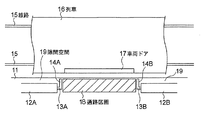
図2に示すように、本実施形態に係るホームドア装置10では、ドア13A,13Bにおける例えば突き合わせ先端部において、好ましくはL字型部14A,14Bが形成されている。このL字型部14A,14Bは、全体として矩形平板状のドア13A,13Bの先部をなす辺部の全体または一部を、車両側(または線路側)に例えば好ましくは90°の角度で折り曲げた形状に形成され、かつ車両側に所要の任意の長さとなるように形成されている。
As shown in FIG. 2, in the home door device 10 according to the present embodiment, preferably L-shaped
ドア13A,13BのL字型部14A,14Bは、ドア13A,13Bの一部として一体化した構造により形成することもできるし、既存の平板状のドア部材に対して別部材として製作した後にドア先端部に上記の取付け関係に基づいて取り付けるように構成することもできる。
The L-shaped
図3は、ホームドア装置10の開動作時の状態を示している。駅ホーム11において、線路15上において列車16が入線し停止すると、次に旅客の乗降のために列車16の各車両の車両ドア17が開く。車両ドア17が開くとき、その開動作に連動して同期的にホームドア装置10のドア13A,13Bも開く。ドア13A,13Bがそれぞれドア筐体12A,12B内に収容されるように動くと、その結果、旅客が移動できる乗降のための通路区画18が形成される。図3において、通路区画18は平面形状として示されているが、実際には、前述の通りドア13A,13Bの先端の箇所にはL字型部14A,14Bが設けられているので、両側に位置する当該L字型部14A,14Bをガイド板として、当該L字型部14A,14Bによって3次元的な空間として乗降用の旅客の通路区画18が形成されている。L字型部14A,14Bは、ドア13A,13Bのホーム側面から列車側に延びた形状で配置されているので、旅客にとって乗降用の通路を形成し、その他の隙間空間19に旅客が進入するのを規制する通路壁部材としての機能も有している。従って、列車16の車両ドア17が開きかつホームドア装置10のドア13A,13Bが開いた状態では、乗降を行う旅客は通路区画18を通って移動する。通路区画18を通過する旅客は、L字型部14A,14Bのために隙間空間19に入り込むことを阻止される。
FIG. 3 shows the state when the home door device 10 is in the opening operation. When the
上記の通り、ホームドア装置10のドア13A,13Bの各々のL字型部14A,14Bは、開動作時に乗降用の通路区画18を形成し、乗降用通路を形成する通路形成部としての機能を有している。
As described above, each L-shaped
図3に示した開動作状態で旅客の乗降が終了すると、列車16では、車両ドア17が閉じ、同時に、連動して同期的にホームドア装置10のドア13A,13Bが閉じられる。その結果、通路区画18に特に旅客等がいない場合には、ホームドア装置10の動作状態は、図2に示された閉動作状態に戻る。
When the passenger's getting on and off ends in the open operation state shown in FIG. 3, in the
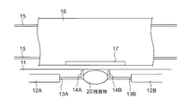
ホームドア装置10のドア13A,13Bが閉じる場合において、通路区画18に旅客等が残留していると、図4に示された状態になる。すなわち、通路区画18に旅客等20が残留していると、当該旅客等の残留物20は、左右から閉じるドア13A,13Bの先部に存するL字型部14A,14Bに挟まれる状態になる。その結果、ドア13A,13Bでは所定の閉動作完了位置まで移動していないにも拘わらず、L字型部14A,14Bは、挟み込まれた残留物20から力(あるいは接触作用)を受けることになる。そこで、例えば、この力を外的負荷として検知することにより、通路区画18での残留物20の存在(有無)を検知することができる。従って、ホームドア装置10のドア13A,13Bが有する形状または構造それ自体の接触等によって残留物の有無を検知することができ、別途の検知手段として特別に光電センサ等を設ける必要はない。またドア13A,13BのL字型部14A,14Bを利用すれば、当該L字型部14A,14Bで形成された通路区画18という2次元空間、さらにL字型部14A,14Bの高さ方向の形状等も考慮に入れると通路区画18を底面部とする3次元空間(「通路区画」の概念に含まれる)に存する残留物を検知することができるという利点を有している。すなわち、残留物の検知領域を立体的なものとして設定することができるという利点を有する。また構造物あるいは形状を利用して接触や力等の物理的媒介を利用して残留物を検知するために、太陽光、雨、雪等の影響を受けることがないという利点も有している。
When the
図5は、閉動作するドア13A,13BのL字型部14A,14Bの挟み込み作用で残留物20を検知するための検知回路を示す。検知回路21による残留物検知の回路構成には、いくつかの異なる原理を利用することができる。図5に示された検知回路21の構成は、もっとも好ましい構成として、ドア13A,13Bの各々を個別に開閉駆動するモータ22に動作量センサ(ストロークセンサや回転量センサ等)23と負荷センサ24を付設し、動作量センサ23から出力される動作量情報と負荷センサ2から出力される負荷情報を入力し、動作量情報が閉動作完了位置を示しておらずかつ設定値以上の負荷情報が発生した場合に、残留物が存在すると判断する残留物判定手段25を備えている。なお、動作量情報のみまたは負荷情報のみで残留物の存在(有無)を判断するように構成することもできる。
検知回路21の構成としては、上記の構成に限定されるものではない。例えば、その他に、L字型部14A,14Bの各々の対向表面等に圧力センサ、接触センサ、触覚センサ等を設け、これらの圧力センサ等から出力される圧力情報、接触情報等で、残留物の有無を検知するように構成することもできる。またL字型部14A,14Bに変形性が高い材質を用いて形成し、その変形量を計測することにより残留物の有無を検知するように構成することもできる。
FIG. 5 shows a detection circuit for detecting the residue 20 by the pinching action of the L-shaped
The configuration of the
次に、図6と図7を参照して通路形成部としての上記のL字型部14A,14Bの変形例、およびドア13A,13Bの変形例を説明する。
Next, with reference to FIG. 6 and FIG. 7, the modification of said L-shaped
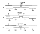
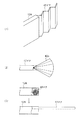
図6の(1)は、ドア13A,13Bの先部に設けられる通路形成部として、L字型部の代わりにU字型部31にすることもできる。湾曲させる方向および湾曲の程度は任意である。U字型部31によってデザイン性を高め、旅客等に対する接触・当接の関係を緩和することができる。
図6の(2)は、ドア13A,13Bにおいて車両側に延設される延設部32の角度を任意に変更した例を示す。L字型部は厳密に直角になるように形成する必要はない。この図に示した延設部32によれば、ドア13A,13Bが閉じられるとき、通路区画18に旅客がいる場合に駅ホーム11の中央側に押し出すことができるという作用を発揮する利点を有している。
図6の(3)は、ドア13A,13Bの先部に設けられる通通路形成部として、T字型部33の例を示している。このT字型部33によれば、車両側への延設部と駅ホーム中央側への延設部とを備えている。
(1) of FIG. 6 can also be made into the U-shaped part 31 instead of L-shaped part as a channel | path formation part provided in the tip part of
(2) of FIG. 6 shows the example which changed arbitrarily the angle of the extending
(3) of FIG. 6 shows an example of the T-shaped
上記の各通路形成部において、ドア13A,13Bの先部に設けられたL字型部等についての高さ方向については、隙間を作ることなく面状に作ることもできるし、さらに複数のスリット状隙間を形成して櫛形の形状に作ることができる。櫛形にするのは、変形性能を高めるためである。また少なくとも1つの孔や開口を形成して作ることもできる。軽量化のためである。
In each of the passage forming portions described above, the height direction of the L-shaped portion or the like provided at the tip of the
図7では、ホームドア装置10に装備される開閉式のドア13A,13Bの変形例を示す。
図7の(1)は、折りたたみ式の構造および形状を有するドア41の例を示す。
図7の(2)は、突き合わせの先端部に折りたたみ傘42aのような機能を有するドア42の例を示す。
図7の(3)は、通常は平面または断面の形状にて渦巻き形態を有し、内部に空気収容部を有し、圧縮空気を供給されると伸長する構造を有したドア43の例を示す。
In FIG. 7, the modification of opening-closing-
(1) of FIG. 7 shows an example of the door 41 having a foldable structure and shape.
(2) of FIG. 7 shows an example of the door 42 having a function like a
(3) of FIG. 7 has an example of a door 43 having a spiral form, usually in the shape of a plane or a cross section, having an air storage portion inside, and having a structure that expands when supplied with compressed air. Show.
以上の実施形態で説明された構成、形状、大きさおよび配置関係については本発明が理解・実施できる程度に概略的に示したものにすぎず、また数値および各構成の組成(材質)等については例示にすぎない。従って本発明は、説明された実施形態に限定されるものではなく、特許請求の範囲に示される技術的思想の範囲を逸脱しない限り様々な形態に変更することができる。 The configurations, shapes, sizes, and arrangement relationships described in the above embodiments are merely schematics to the extent that the present invention can be understood and practiced, and numerical values, compositions (materials) of each configuration, etc. Is merely an example. Therefore, the present invention is not limited to the described embodiments, and can be modified in various forms without departing from the scope of the technical idea shown in the claims.
本発明に係るホームドア装置は、駅ホーム上の旅客の安全を確保すると共に、開閉式ドアの形状または構造を改変することにより、閉動作時に乗降通路区画に残留する物体を接触作用により検知可能にする通行形成部を備える用にしたため、確実な残留物検知に利用される。 INDUSTRIAL APPLICABILITY The home door apparatus according to the present invention ensures the safety of the passenger on the station platform, and can detect the object remaining in the entrance / exit section by the contact action at the closing operation by modifying the shape or structure of the openable door. It is used for reliable residue detection because it is used to provide a traffic formation part.
10 ホームドア装置
11 駅ホーム
12A,12B ドア筐体
13A,13B ドア
14A,14B L字型部
15 線路
16 列車
17 車両ドア
18 通路区画
19 隙間空間
20 残留物
21 検知回路
22 モータ
23 動作量センサ
24 負荷センサ
25 残留物判定手段
31 U字型部
32 延設部
33 T字型部
41〜43 ドア
100 列車
101 車両ドア
102 ホームドア装置
103 ドア
104 スペース
105 光電センサ
106 光線
DESCRIPTION OF SYMBOLS 10
Claims (5)
Priority Applications (1)
| Application Number | Priority Date | Filing Date | Title |
|---|---|---|---|
| JP2013102211A JP6525428B2 (en) | 2013-05-14 | 2013-05-14 | Home door device |
Applications Claiming Priority (1)
| Application Number | Priority Date | Filing Date | Title |
|---|---|---|---|
| JP2013102211A JP6525428B2 (en) | 2013-05-14 | 2013-05-14 | Home door device |
Publications (2)
| Publication Number | Publication Date |
|---|---|
| JP2014221613A JP2014221613A (en) | 2014-11-27 |
| JP6525428B2 true JP6525428B2 (en) | 2019-06-05 |
Family
ID=52121408
Family Applications (1)
| Application Number | Title | Priority Date | Filing Date |
|---|---|---|---|
| JP2013102211A Active JP6525428B2 (en) | 2013-05-14 | 2013-05-14 | Home door device |
Country Status (1)
| Country | Link |
|---|---|
| JP (1) | JP6525428B2 (en) |
Families Citing this family (6)
| Publication number | Priority date | Publication date | Assignee | Title |
|---|---|---|---|---|
| JP6789501B2 (en) * | 2017-02-27 | 2020-11-25 | 株式会社石井鐵工所 | Platform door |
| CN108622109B (en) * | 2018-08-03 | 2023-11-17 | 北京市市政工程设计研究总院有限公司 | Platform door and train door clearance detection device |
| JP7278143B2 (en) * | 2019-04-26 | 2023-05-19 | 三菱電機株式会社 | Platform fence |
| CN110043170A (en) * | 2019-05-17 | 2019-07-23 | 中国铁路设计集团有限公司 | Tilting high platform door |
| DE102021110320B3 (en) * | 2021-04-22 | 2022-07-07 | Cambaum Gmbh | Retrofittable station canopy with integrated passenger guidance system |
| CN117465483B (en) * | 2023-12-27 | 2024-04-09 | 江苏明伟万盛科技有限公司 | Visual safety detection device for gap of rail transit platform |
Family Cites Families (4)
| Publication number | Priority date | Publication date | Assignee | Title |
|---|---|---|---|---|
| JP3278642B2 (en) * | 1998-12-01 | 2002-04-30 | 株式会社東京精密 | Safety doors and devices for manufacturing or inspecting semiconductors with safety doors |
| JP2001164833A (en) * | 1999-12-13 | 2001-06-19 | Hitachi Ltd | Platform door device |
| CA2502537C (en) * | 2005-03-30 | 2009-08-18 | Bahattin Gunes | Safety entrance norm (sen) |
| JP5030432B2 (en) * | 2006-02-09 | 2012-09-19 | 三菱重工業株式会社 | Platform fence, failure detection device for platform fence, failure detection method for platform fence |
-
2013
- 2013-05-14 JP JP2013102211A patent/JP6525428B2/en active Active
Also Published As
| Publication number | Publication date |
|---|---|
| JP2014221613A (en) | 2014-11-27 |
Similar Documents
| Publication | Publication Date | Title |
|---|---|---|
| JP6525428B2 (en) | Home door device | |
| US10494853B2 (en) | Door system with sensor unit for contactless passenger compartment monitoring | |
| JP5254566B2 (en) | Elevator door equipment | |
| KR101471544B1 (en) | Screen door opening and closing method for screen safety device on train platform | |
| CN107000772A (en) | Door system with sensor unit and communication device | |
| JP2015037988A (en) | Elevator control device and elevator system | |
| JP2012121483A5 (en) | ||
| EP2910448A1 (en) | Railroad vehicle and plug door for railroad vehicle | |
| JP2018199434A (en) | Movable platform fence and row of movable platform fence | |
| CN107208452A (en) | Wind safety door | |
| KR101901411B1 (en) | Door Assembly | |
| JP5850606B2 (en) | Gate | |
| CN101628682B (en) | Elevator door device | |
| CN204423448U (en) | A kind of parking lot card feed device | |
| JP5909254B2 (en) | Platform door device and platform door protector used therefor | |
| JP6208530B2 (en) | Home door device | |
| KR20110055026A (en) | Obstacle detection apparatus of platform screen door | |
| CN103287955B (en) | Safety apparatus for elevator entrance | |
| EP2910447A1 (en) | Railroad vehicle and plug door for railroad vehicle | |
| US8595975B2 (en) | Gateway for providing controlled access from an entrance point to an exit point | |
| JP6085457B2 (en) | Home safety fence | |
| AU2015334877A1 (en) | Door system for an elevator installation | |
| JP7321073B2 (en) | Platform door device | |
| CN103863928B (en) | Elevator doorway device | |
| JP6501335B2 (en) | Information display device for transparent area |
Legal Events
| Date | Code | Title | Description |
|---|---|---|---|
| A621 | Written request for application examination |
Free format text: JAPANESE INTERMEDIATE CODE: A621 Effective date: 20160331 |
|
| A977 | Report on retrieval |
Free format text: JAPANESE INTERMEDIATE CODE: A971007 Effective date: 20170113 |
|
| A131 | Notification of reasons for refusal |
Free format text: JAPANESE INTERMEDIATE CODE: A131 Effective date: 20170124 |
|
| A521 | Written amendment |
Free format text: JAPANESE INTERMEDIATE CODE: A523 Effective date: 20170327 |
|
| A02 | Decision of refusal |
Free format text: JAPANESE INTERMEDIATE CODE: A02 Effective date: 20170711 |
|
| A521 | Written amendment |
Free format text: JAPANESE INTERMEDIATE CODE: A523 Effective date: 20171006 |
|
| A911 | Transfer of reconsideration by examiner before appeal (zenchi) |
Free format text: JAPANESE INTERMEDIATE CODE: A911 Effective date: 20171013 |
|
| A912 | Removal of reconsideration by examiner before appeal (zenchi) |
Free format text: JAPANESE INTERMEDIATE CODE: A912 Effective date: 20171102 |
|
| A521 | Written amendment |
Free format text: JAPANESE INTERMEDIATE CODE: A523 Effective date: 20180914 |
|
| A521 | Written amendment |
Free format text: JAPANESE INTERMEDIATE CODE: A523 Effective date: 20190125 |
|
| A61 | First payment of annual fees (during grant procedure) |
Free format text: JAPANESE INTERMEDIATE CODE: A61 Effective date: 20190430 |
|
| R150 | Certificate of patent or registration of utility model |
Ref document number: 6525428 Country of ref document: JP Free format text: JAPANESE INTERMEDIATE CODE: R150 |