JP6524575B2 - lighting equipment - Google Patents

lighting equipment Download PDF

Info

Publication number
JP6524575B2
JP6524575B2 JP2014246152A JP2014246152A JP6524575B2 JP 6524575 B2 JP6524575 B2 JP 6524575B2 JP 2014246152 A JP2014246152 A JP 2014246152A JP 2014246152 A JP2014246152 A JP 2014246152A JP 6524575 B2 JP6524575 B2 JP 6524575B2
Authority
JP
Japan
Prior art keywords
power supply
supply unit
case
wiring board
printed wiring
Prior art date
Legal status (The legal status is an assumption and is not a legal conclusion. Google has not performed a legal analysis and makes no representation as to the accuracy of the status listed.)
Active
Application number
JP2014246152A
Other languages
Japanese (ja)
Other versions
JP2016110791A (en
Inventor
博司 海路
博司 海路
Current Assignee (The listed assignees may be inaccurate. Google has not performed a legal analysis and makes no representation or warranty as to the accuracy of the list.)
Panasonic Intellectual Property Management Co Ltd
Original Assignee
Panasonic Intellectual Property Management Co Ltd
Priority date (The priority date is an assumption and is not a legal conclusion. Google has not performed a legal analysis and makes no representation as to the accuracy of the date listed.)
Filing date
Publication date
Application filed by Panasonic Intellectual Property Management Co Ltd filed Critical Panasonic Intellectual Property Management Co Ltd
Priority to JP2014246152A priority Critical patent/JP6524575B2/en
Publication of JP2016110791A publication Critical patent/JP2016110791A/en
Application granted granted Critical
Publication of JP6524575B2 publication Critical patent/JP6524575B2/en
Active legal-status Critical Current
Anticipated expiration legal-status Critical

Links

Images

Description

本発明は、光源に給電して点灯させる電源装置を備えた明器具に関する。 The present invention relates to a lighting device with a power supply for lighting and power the light source.

従来例として、特許文献1記載の照明装置を例示する。この従来例は、照明台などに設置されて屋外で使用される投光器であり、照明器具、電源ユニット、電源ケーブルなどを備える。照明器具は、光源である発光ダイオード(LED)、LEDから放射される光を前方に反射する反射板、LED及び反射板を保持する器具本体、器具本体を支持する支持金具(アーム)などで構成される。   As a prior art example, the illuminating device of patent document 1 is illustrated. This conventional example is a light projector installed in a lighting stand or the like and used outdoors, and includes a lighting fixture, a power supply unit, a power cable, and the like. The luminaire comprises a light emitting diode (LED) as a light source, a reflector plate for reflecting light emitted from the LED forward, an instrument body for holding the LED and the reflector plate, and a support bracket (arm) for supporting the instrument body. Be done.

電源ユニットは、4台の電源装置、各電源装置の出力端に一端が接続された複数の電線、電源装置並びに電線の一部を収納するケースなどを有する。各電源装置は、商用の電力系統から給電線を介して給電される交流電力を直流電力に変換する電力変換回路と、当該電力変換回路を内部に収納した筐体とを有する。筐体は、金属板を加工することで扁平な矩形箱状に形成されている。   The power supply unit includes four power supply devices, a plurality of electric wires whose one end is connected to the output end of each power supply device, the power supply device, and a case for housing a part of the electric wires. Each power supply device includes a power conversion circuit that converts alternating current power supplied from a commercial power system via a feeder line into direct current power, and a housing that houses the power conversion circuit therein. The housing is formed in a flat rectangular box shape by processing a metal plate.

ケースは、前後の両端が開口した角筒状のケース本体と、ケース本体の開口を閉塞する2つの蓋部とを有する。ケース本体は、左右両側の内側面から、上下両側の内側面と対向する突条が前後方向に沿って突設されている。そして、これらの突条と上下両側の内側面との間に形成される隙間に、2枚の取付板の端部がそれぞれ係止される。   The case has a rectangular cylindrical case main body whose front and rear ends are open, and two lids closing the opening of the case main body. From the inner side surfaces of the left and right sides of the case main body, protrusions are provided in the front-rear direction so as to protrude from the upper and lower inner side surfaces. Then, the end portions of the two mounting plates are respectively locked in the gaps formed between the ridges and the inner side surfaces of the upper and lower sides.

取付板は、前後方向に長い長方形状の金属板からなる。そして、各取付板には、それぞれ2台の電源装置が、一対の取付部材を用いて前後方向に並ぶように固定される。つまり、一面側に2台の電源装置が取り付けられた取付板を前面側よりケース本体内に挿入すると、取付板の左右両端部が上側の一対の隙間若しくは下側の一対の隙間に係止される。そして、ケース本体の外側より、複数のねじでねじ止めすることにより、各取付板がケース本体に固定される。   The mounting plate is formed of a rectangular metal plate long in the front-rear direction. Then, two power supply devices are fixed to each mounting plate so as to be aligned in the front-rear direction using a pair of mounting members. That is, when the mounting plate to which two power supplies are attached on one side is inserted into the case main body from the front side, the left and right ends of the mounting plate are locked in the upper pair of gaps or the lower pair of gaps. Ru. Then, each mounting plate is fixed to the case main body by screwing with a plurality of screws from the outside of the case main body.

特開2014−183033号公報JP, 2014-183033, A

ところで、特許文献1記載の従来例(電源ユニット)では、金属製のケース本体内に、同じく金属製の筐体(電源装置)が収納されているので、小型化及び軽量化が困難である。   By the way, in the conventional example (power supply unit) described in Patent Document 1, since the metal case (power supply device) is similarly housed in the metal case main body, it is difficult to reduce the size and weight.

本発明は、上記課題に鑑みてなされたものであり、小型化及び軽量化を図ることを目的とする。   The present invention is made in view of the above-mentioned subject, and aims at attaining size reduction and weight reduction.

本発明の照明器具は、電源ユニットと、前記電源ユニットから給電されて点灯する1乃至複数の光源ユニットとを備え、前記電源ユニットは、外部から入力する電力を電力変換する1乃至複数の電源装置と、1乃至複数の前記電源装置を内部に収納するケースとを備え、1乃至複数の前記電源装置は、平板状のプリント配線板と、前記プリント配線板の片面又は両面に実装される複数の回路素子と、前記プリント配線板の片面における端部から立ち上がる壁部とを有し、前記複数の回路素子のうちで相対的に発熱量の多い特定の回路素子が前記壁部と熱的に結合されるように構成され、前記ケースは、軸方向の端に挿入口が開口した角筒状に形成されるケース本体と、前記挿入口を塞ぐ蓋部と、1乃至複数の締結部材とを有し、前記ケース本体は、内周面に一対又は複数対の溝部が設けられ、前記一対又は複数対の溝部は、前記挿入口から前記プリント配線板の端部が挿入可能であり、且つ挿入後の前記端部を厚み方向に挟み込んで支持するように構成され、前記1乃至複数の締結部材は、前記ケース本体の外側から、前記ケース本体と前記壁部とを締結するように構成され、前記電源ユニットは、前記ケース本体の軸方向を上下方向に沿わせるようにして、前記1乃至複数の光源ユニットの背面側に配置されることを特徴とする。 A luminaire according to the present invention includes a power supply unit, and one or more light source units that are supplied with power from the power supply unit and light up, and the power supply unit performs one or more power supply devices for converting power input from the outside. And a case for housing one or more of the power supply devices therein, wherein the one or more power supply devices include a flat printed wiring board and a plurality of the power supply devices mounted on one side or both sides of the printed wiring board A specific circuit element having a circuit element and a wall part rising from an end on one side of the printed wiring board and having a relatively large amount of heat generation among the plurality of circuit elements is thermally coupled to the wall part The case has a case main body formed in an angular cylindrical shape having an insertion opening at an axial end, a lid for closing the insertion opening, and one or more fastening members. And the case book The inner peripheral surface is provided with a pair or plural pairs of groove portions, and the pair or plural pairs of groove portions can be inserted into the end portion of the printed wiring board from the insertion port, and the end portion after insertion The one or more fastening members are configured to fasten the case main body and the wall portion from the outside of the case main body, and the power supply unit is configured to hold the support in the thickness direction. It is characterized in that it is disposed on the back side of the one or more light source units so that the axial direction of the case body is vertically aligned .

本発明の明器具は、小型化及び軽量化を図ることができるという効果がある。 Lighting devices of the present invention, there is an effect that it is possible to reduce the size and weight.

本発明に係る照明器具の実施形態を示す正面図である。It is a front view showing an embodiment of a lighting fixture concerning the present invention. 同上の照明器具の右側面図である。It is a right view of the lighting fixture same as the above. 同上の照明器具の後方から見た斜視図である。It is the perspective view seen from the back of the lighting fixture same as the above. 本発明に係る電源ユニットの実施形態を示し、図4Aは一方の蓋部を取り外した状態の側面図、図4Bは図4AのX−X線断面矢視図である。FIG. 4A shows an embodiment of a power supply unit according to the present invention, FIG. 4A is a side view in a state in which one lid is removed, and FIG. 4B is a sectional view taken along line XX in FIG. 4A. 同上の電源ユニットの一部省略した分解斜視図である。It is the disassembled perspective view which partially omitted the power supply unit same as the above. 同上の電源ユニットの一部省略した斜視図である。It is the perspective view which partially omitted the power supply unit same as the above.

以下、本発明に係る電源ユニットの実施形態、並びに本発明に係る照明器具の実施形態について、図面を参照して詳細に説明する。本実施形態の照明器具は、特許文献1記載の従来例と同じく、投光器を例示するが、本発明の技術思想が適用可能な照明器具は本実施形態に限定されない。   Hereinafter, an embodiment of a power supply unit according to the present invention and an embodiment of a lighting apparatus according to the present invention will be described in detail with reference to the drawings. Although the lighting fixture of this embodiment exemplifies a light projector similarly to the prior art example of patent document 1, the lighting fixture which can apply the technical thought of this invention is not limited to this embodiment.

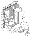
本実施形態の照明器具は、図1〜図3に示すように、複数(図示例では4つ)の光源ユニット1と、複数の光源ユニット1に給電する電源ユニット8とを備える。さらに、本実施形態の照明器具は、複数の光源ユニット1を連結する連結部材と、アーム16とを備えることが好ましい。ただし、照明器具を構成する光源ユニット1の数は4つに限定されず、1〜3つ、あるいは5つ以上でも構わない。なお、以下の説明において、特に断りの無い限り、図1において上下、左右、前後の各方向を規定し、紙面の手前側を前とする。   As shown in FIGS. 1 to 3, the lighting fixture of the present embodiment includes a plurality of (four in the illustrated example) light source units 1 and a power supply unit 8 for supplying power to the plurality of light source units 1. Furthermore, it is preferable that the lighting fixture of the present embodiment includes a connecting member that connects a plurality of light source units 1 and an arm 16. However, the number of light source units 1 constituting the lighting fixture is not limited to four, and may be one to three, or five or more. In the following description, unless otherwise noted, the upper, lower, left, and right directions in FIG. 1 are defined, and the front side of the sheet is the front.

光源ユニット1は、図2及び図3に示すように、光源に相当するLEDモジュールと、放熱部材3とを有する。LEDモジュールは、複数個の発光ダイオード(LED)と、実装基板とを有することが好ましい。LEDは、例えば、従来周知であるパッケージ型の白色LEDである。実装基板は、矩形平板状のアルミ基板で構成されることが好ましい。LEDは、実装基板の前面に、縦横に並べて実装される。また、実装基板の前面にレセプタクルコネクタが実装される。レセプタクルコネクタは、実装基板の前面に形成される配線用の導体を介して、各LEDの電極(カソード及びアノード)と電気的に接続される。   The light source unit 1 has the LED module corresponded to a light source, and the thermal radiation member 3, as shown to FIG. 2 and FIG. The LED module preferably includes a plurality of light emitting diodes (LEDs) and a mounting substrate. The LEDs are, for example, package-type white LEDs that are conventionally known. The mounting substrate is preferably configured of a rectangular flat aluminum substrate. The LEDs are mounted vertically and horizontally on the front surface of the mounting substrate. Also, the receptacle connector is mounted on the front surface of the mounting substrate. The receptacle connector is electrically connected to the electrode (cathode and anode) of each LED through a wiring conductor formed on the front surface of the mounting substrate.

放熱部材3は、図2及び図3に示すように、ベース部30、一対の縁部31、複数の放熱板32で構成されることが好ましい。なお、ベース部30、縁部31並びに放熱板32は、例えば、アルミニウム合金などの熱伝導性に優れた材料で形成されることが好ましい。ベース部30は、矩形平板状に形成される。ベース部30の前面にLEDモジュールが固定される。また、ベース部30の前面には、LEDモジュールを覆い隠すようにカバー7が取り付けられる(図1参照)。カバー7は、ポリカーボネート樹脂などの透光性を有する合成樹脂材料により、扁平な矩形の箱状に形成される。一対の縁部31は、上下方向を長手方向とする直方体状であって、ベース部30の左端縁と右端縁においてベース部30と一体に形成される。なお、縁部31の厚み(前後方向の幅)は、ベース部30の厚みよりも十分に大きく形成されている。   As shown in FIGS. 2 and 3, the heat dissipating member 3 is preferably configured by a base portion 30, a pair of edge portions 31, and a plurality of heat dissipating plates 32. In addition, it is preferable that the base part 30, the edge part 31, and the heat sink 32 are formed with the material excellent in thermal conductivity, such as aluminum alloy, for example. The base portion 30 is formed in a rectangular flat plate shape. The LED module is fixed to the front of the base 30. In addition, a cover 7 is attached to the front of the base portion 30 so as to cover the LED module (see FIG. 1). The cover 7 is formed in a flat rectangular box shape by a translucent synthetic resin material such as polycarbonate resin. The pair of edge portions 31 is a rectangular parallelepiped whose longitudinal direction is the vertical direction, and is integrally formed with the base portion 30 at the left end edge and the right end edge of the base portion 30. The thickness (the width in the front-rear direction) of the edge portion 31 is formed sufficiently larger than the thickness of the base portion 30.

連結部材は、図1〜図3に示すように、第1連結部材10、第2連結部材11、第3連結部材12並びに補助連結部材を含むことが好ましい。   It is preferable that a connection member contains the 1st connection member 10, the 2nd connection member 11, the 3rd connection member 12, and an auxiliary connection member, as shown in Drawings 1-3.

第1連結部材10は、帯状の主片100と、主片100の長手方向に沿って主片100の厚み方向に突出する補助片101とを有する(図2参照)。なお、主片100と補助片101とは、ステンレス鋼板などの金属板が長手方向に沿って折り曲げられることで一体に形成される。   The first connection member 10 has a strip-shaped main piece 100 and an auxiliary piece 101 projecting in the thickness direction of the main piece 100 along the longitudinal direction of the main piece 100 (see FIG. 2). The main piece 100 and the auxiliary piece 101 are integrally formed by bending a metal plate such as a stainless steel plate along the longitudinal direction.

また、第1連結部材10は、主片100の長手方向における両端及び中央に、それぞれ突片102、103が設けられている。ただし、中央の突片103は、両端の突片102のほぼ2倍の長さ寸法を有している。また、中央の突片103の先端が、外向きに折り曲げられている。各突片102、103には、それぞれ1つ又は2つのねじ挿通孔が設けられる(図1及び図3参照)。   Further, the first connecting member 10 is provided with protruding pieces 102 and 103 at both ends and the center in the longitudinal direction of the main piece 100, respectively. However, the central projecting piece 103 has a length twice as large as that of the projecting pieces 102 at both ends. Further, the tip of the central protrusion 103 is bent outward. Each protrusion 102, 103 is provided with one or two screw insertion holes, respectively (see FIGS. 1 and 3).

第1連結部材10は、図3に示すように、各突片102、103が、放熱部材3の縁部31にねじ止めされることで2つの光源ユニット1に取り付けられる。すなわち、各突片102、103のねじ挿通孔に挿通されるねじ104が縁部31のねじ孔にねじ込まれる。   As shown in FIG. 3, the first connection member 10 is attached to the two light source units 1 by screwing the protrusions 102 and 103 to the edge portion 31 of the heat dissipation member 3. That is, the screw 104 inserted into the screw insertion hole of each of the protrusions 102 and 103 is screwed into the screw hole of the edge portion 31.

第2連結部材11は、帯状の金属板(例えば、ステンレス鋼板など)で構成される。ただし、第2連結部材11の中央部110は、両側の端部111に対して厚み方向に突出している。中央部110には、3つのねじ挿通孔が設けられる。一方、各端部111には、2つのねじ挿通孔がそれぞれ設けられる(図3参照)。   The second connection member 11 is formed of a strip-like metal plate (for example, a stainless steel plate or the like). However, the central portion 110 of the second connection member 11 protrudes in the thickness direction with respect to the end portions 111 on both sides. The central portion 110 is provided with three screw insertion holes. On the other hand, two screw insertion holes are provided at each end 111 (see FIG. 3).

第2連結部材11は、放熱部材3の縁部31にねじ止めされることで2つの光源ユニット1に取り付けられる。すなわち、中央部110及び各端部111のねじ挿通孔に挿通されるねじ112が縁部31のねじ孔にねじ込まれる(図2参照)。   The second connection member 11 is attached to the two light source units 1 by being screwed to the edge portion 31 of the heat dissipation member 3. That is, the screw 112 inserted into the screw insertion hole of the central portion 110 and each end portion 111 is screwed into the screw hole of the edge portion 31 (see FIG. 2).

第3連結部材12は、帯状の金属板(例えば、ステンレス鋼板など)で構成される。ただし、第3連結部材12は、長手方向に沿った両端部が厚み方向に折り曲げられることで補強されている。また、第3連結部材12は、長手方向の両端にそれぞれ2つのねじ挿通孔が設けられている。これらのねじ挿通孔は、第3連結部材12の短手方向に並ぶように設けられる。第3連結部材12は、放熱部材3の縁部31にねじ止めされることで4つの光源ユニット1に取り付けられる(図1参照)。   The third connecting member 12 is formed of a strip-like metal plate (for example, a stainless steel plate or the like). However, the third connecting member 12 is reinforced by bending both ends along the longitudinal direction in the thickness direction. Further, the third connecting member 12 is provided with two screw insertion holes at both ends in the longitudinal direction. These screw insertion holes are provided to be aligned in the lateral direction of the third connecting member 12. The third connection member 12 is attached to the four light source units 1 by being screwed to the edge portion 31 of the heat dissipation member 3 (see FIG. 1).

補助連結部材は、図1〜図3に示すように、一対のアーム取付部材13と、一対の補強部材14とで構成される。アーム取付部材13は、角樋状の固定部130と、一対の取付部131と、軸受け部132とを有する。なお、固定部130と取付部131と軸受け部132とは、例えば、アルミダイカストによって一体に形成されることが好ましい。   The auxiliary connection member is constituted by a pair of arm attachment members 13 and a pair of reinforcement members 14 as shown in FIGS. 1 to 3. The arm attachment member 13 has an angular hook-shaped fixed portion 130, a pair of attachment portions 131, and a bearing portion 132. Preferably, the fixing portion 130, the mounting portion 131, and the bearing portion 132 are integrally formed by, for example, aluminum die casting.

一対の取付部131は、長尺の円錐台形状に形成され、固定部130から後方に突出する。なお、各取付部131の先端部には、雌ねじが形成されている。   The pair of attachment portions 131 are formed in a long truncated cone shape and project rearward from the fixing portion 130. A female screw is formed at the tip of each mounting portion 131.

軸受け部132は、円筒形状に形成され、一対の取付部131の間に配置されて各取付部131並びに固定部130と繋がっている。軸受け部132の中心には、ねじ孔が設けられる。   The bearing portion 132 is formed in a cylindrical shape, disposed between the pair of attachment portions 131 and connected to the attachment portions 131 and the fixing portion 130. At the center of the bearing portion 132, a screw hole is provided.

補強部材14は、図3に示すように、帯状の金属板(例えば、ステンレス鋼板など)で構成される。ただし、補強部材14は、長手方向に沿った両端部が厚み方向に折り曲げられることで補強されている。一対の補強部材14は、上下方向に並ぶように、左右両側のアーム取付部材13の取付部131に取り付けられる。すなわち、補強部材14の両端に設けられるねじ挿通孔にボルト140が挿通され、そのボルト140が取付部131の先端部の雌ねじにねじ込まれてねじ止めされる(図2及び図3参照)。   As shown in FIG. 3, the reinforcing member 14 is formed of a band-like metal plate (for example, a stainless steel plate or the like). However, the reinforcing member 14 is reinforced by bending both ends along the longitudinal direction in the thickness direction. The pair of reinforcing members 14 are attached to the attachment portions 131 of the arm attachment members 13 on the left and right sides so as to be aligned in the vertical direction. That is, the bolt 140 is inserted into the screw insertion holes provided at both ends of the reinforcing member 14, and the bolt 140 is screwed into the female screw at the tip of the mounting portion 131 and screwed (see FIGS. 2 and 3).

アーム16は、図2及び図3に示すように、固定板160と、固定板160の左右両端から斜め上向きに立ち上がる一対の立ち上げ片161と、各立ち上げ片161の先端から斜め上向きに立ち上がる支持片162とが金属板によって一体に形成されている。   As shown in FIG. 2 and FIG. 3, the arm 16 stands obliquely upward from the fixed plate 160, a pair of rising pieces 161 rising obliquely upward from the left and right ends of the fixed plate 160, and the tip of each rising piece 161. The support piece 162 is integrally formed of a metal plate.

固定板160は、略中心に円形の固定孔1601が貫通し、固定孔1601よりも後方に、固定孔1601を中心とする半円弧状の長孔1600が貫通している(図3参照)。そして、固定孔1601に挿通されるボルトと、長孔1600に挿通されるボルトとで固定板160が照明台(コンクリート製の土台)などに固定される。また、長孔1600に挿通されるボルトを緩めることにより、アーム16の向き(光源ユニット1の向き)を略180度の範囲で変更することができる。   In the fixing plate 160, a circular fixing hole 1601 penetrates substantially at the center, and a semicircular long hole 1600 centering on the fixing hole 1601 penetrates behind the fixing hole 1601 (see FIG. 3). Then, the fixing plate 160 is fixed to a lighting platform (a base made of concrete) or the like by a bolt inserted into the fixing hole 1601 and a bolt inserted into the long hole 1600. Further, by loosening the bolt inserted into the long hole 1600, the direction of the arm 16 (the direction of the light source unit 1) can be changed within a range of about 180 degrees.

各支持片162は、先端部に円形の挿通孔が貫通している。故に、挿通孔に挿通したボルト163が、アーム取付部材13の軸受け部132のねじ孔にねじ込まれることにより、連結部材で連結された4つの光源ユニット1をアーム16で回転可能に支持することができる。   Each support piece 162 has a circular insertion hole penetrating at its tip. Therefore, the four light source units 1 connected by the connecting member can be rotatably supported by the arm 16 by screwing the bolt 163 inserted into the insertion hole into the screw hole of the bearing portion 132 of the arm mounting member 13. it can.

ところで、下側の補強部材14には、配線ボックス15がねじ止めによって取り付けられる(図3参照)。   The wiring box 15 is attached to the lower reinforcing member 14 by screwing (see FIG. 3).

配線ボックス15は、金属材料によって矩形箱状に形成される。配線ボックス15内には、中継用の端子台が収納される。この端子台は、電力系統から交流電力を供給するための電源ケーブルと、電源ユニット8に前記交流電力を供給するための電源ケーブル9とを電気的に接続するように構成される。   The wiring box 15 is formed in a rectangular box shape by a metal material. A terminal block for relay is accommodated in the wiring box 15. The terminal block is configured to electrically connect a power supply cable for supplying AC power from the power system and the power supply cable 9 for supplying the AC power to the power supply unit 8.

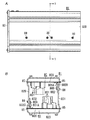
電源ユニット8は、図4A及び図4Bに示すように、2つの電源装置80と、これら2つの電源装置80を内部に収納するケース81とを備える。ただし、以下の電源ユニット8に関する説明においては、図5において、上下、左右、前後の各方向を規定する。   The power supply unit 8 includes, as shown in FIGS. 4A and 4B, two power supplies 80 and a case 81 for housing the two power supplies 80 therein. However, in the following description regarding the power supply unit 8, in FIG.

各電源装置80は、外部(電力系統)から供給される交流電力を2つの光源ユニット1に必要とされる電力(直流電力)に変換する電力変換回路を有することが好ましい。電力変換回路は、例えば、全波整流器、力率改善回路(昇圧チョッパ回路)、DC/DCコンバータ(降圧チョッパ回路)などで構成されることが好ましい。各電源ブロック80は、図4B、図5及び図6に示すように、プリント配線板800の表面に、電力変換回路を構成する多数の回路素子(回路部品)801が実装されて構成される。また、各電源ブロック80は、先端にプラグコネクタが設けられた出力ケーブルを有することが好ましい。これらの出力ケーブルは、ケース81の外に引き出され、光源ユニット1のレセプタクルコネクタと直接、若しくは別の電線ケーブルを介して、電気的に接続されることが好ましい。   Each power supply device 80 preferably includes a power conversion circuit that converts AC power supplied from the outside (power system) into power (DC power) required for the two light source units 1. The power conversion circuit preferably includes, for example, a full-wave rectifier, a power factor correction circuit (boost chopper circuit), a DC / DC converter (buck chopper circuit), and the like. As shown in FIG. 4B, FIG. 5 and FIG. 6, each power supply block 80 is configured by mounting a large number of circuit elements (circuit components) 801 constituting a power conversion circuit on the surface of a printed wiring board 800. Each power supply block 80 preferably has an output cable provided with a plug connector at its tip. These output cables are preferably drawn out of the case 81 and electrically connected to the receptacle connector of the light source unit 1 directly or through another electric wire cable.

さらに、各電源ブロック80は、プリント配線板800の片面における端部から立ち上がる壁部802を有する。壁部802は、熱の良導体である材料(例えば、アルミ若しくはアルミ合金)によって矩形平板状に形成される。また、壁部802は、長手方向に沿った一方の端縁における前端及び後端から突出する一対のL字形状の脚8020を備えることが好ましい(図4B参照)。壁部802は、これら一対の脚8020がプリント配線板800の実装面(回路素子801が実装されている面)に取り付けられることにより、前記実装面の法線方向(上下方向)に沿って起立するように設けられることが好ましい。また、壁部802は、厚み方向に貫通する複数のねじ孔8021が長手方向に並ぶように設けられることが好ましい(図5参照)。さらに、壁部802は、プリント配線板800に実装される回路素子801のうち、力率改善回路やDC/DCコンバータのスイッチング素子などに用いられる半導体素子(例えば、パワーMOSFETなど)801Aと熱的に結合される。なお、これらの半導体素子801Aは、通常、放熱器(放熱板)を有している。そして、放熱器に設けられるねじ挿通孔に挿通されるねじ803が、壁部802に設けられるねじ孔8022にねじ込まれることにより、半導体素子801Aと壁部802が熱的に結合される(図4B及び図5参照)。   Furthermore, each power supply block 80 has a wall portion 802 rising from an end on one side of the printed wiring board 800. The wall portion 802 is formed in a rectangular flat plate shape by a material (for example, aluminum or an aluminum alloy) which is a good conductor of heat. The wall portion 802 preferably includes a pair of L-shaped legs 8020 projecting from the front end and the rear end at one end along the longitudinal direction (see FIG. 4B). The wall portion 802 is erected along the normal direction (vertical direction) of the mounting surface by attaching the pair of legs 8020 to the mounting surface (surface on which the circuit element 801 is mounted) of the printed wiring board 800 Preferably, they are provided. The wall portion 802 is preferably provided such that a plurality of screw holes 8021 penetrating in the thickness direction are arranged in the longitudinal direction (see FIG. 5). Furthermore, the wall portion 802 is a semiconductor element (for example, a power MOSFET etc.) 801A used as a power factor improvement circuit or a switching element of a DC / DC converter among the circuit elements 801 mounted on the printed wiring board 800 Combined with In addition, these semiconductor elements 801A usually have a radiator (heat sink). Then, the semiconductor element 801A and the wall portion 802 are thermally coupled by screwing the screw 803 inserted through the screw insertion hole provided in the radiator into the screw hole 8022 provided in the wall portion 802 (FIG. 4B) And FIG. 5).

ケース81は、ケース本体82と、2つの蓋部83、84とを有することが好ましい(図3参照)。ケース本体82は、例えば、アルミ又はアルミ合金が押出成形されることにより、軸方向の両端が開口した角筒状に形成されることが好ましい。また、ケース本体82は、左側の側壁820の上部と下部の内側面にそれぞれ溝部85が形成されることが好ましい。さらに、ケース本体82は、右側の側壁821の上部と下部の内側面にもそれぞれ溝部85が形成されることが好ましい(図4B及び図5参照)。これらの溝部85は、ケース本体82の一方の開口端から他方の開口端まで真っ直ぐ且つ互いに平行となるように構成されることが好ましい。なお、溝部85の幅は、プリント配線板800の厚みよりも僅かに大きい程度の寸法であればよい。   The case 81 preferably includes a case body 82 and two lids 83 and 84 (see FIG. 3). The case main body 82 is preferably formed in a rectangular tube shape in which both ends in the axial direction are opened by, for example, extrusion molding of aluminum or an aluminum alloy. Preferably, in the case body 82, grooves 85 are formed on the upper and lower inner side surfaces of the left side wall 820, respectively. Furthermore, in the case body 82, it is preferable that grooves 85 be formed on the upper and lower inner side surfaces of the right side wall 821 (see FIGS. 4B and 5). The grooves 85 are preferably configured to be straight and parallel to each other from one open end of the case body 82 to the other open end. The width of the groove 85 may be a size slightly larger than the thickness of the printed wiring board 800.

また、ケース本体82の下側の側壁823の後端部には、4つのケーブル挿通孔が貫通している。これら4つのケーブル挿通孔には、それぞれ出力ケーブルが挿通され、止め金具によって出力ケーブルが側壁823に固定される。   Further, four cable insertion holes pass through the rear end portion of the lower side wall 823 of the case main body 82. An output cable is penetrated by these four cable penetration holes, respectively, and an output cable is fixed to side wall 823 by a clasp.

蓋部83、84は、例えば、アルミダイカストによって平板状に形成されることが好ましい。これら2つの蓋部83、84は、ケース本体82の軸方向の端部にそれぞれねじ止めされることにより、ケース本体82の両端の開口を閉塞するように構成されることが好ましい(図2及び図3参照)。ただし、各蓋部83、84とケース本体82の端部との間に防水パッキンが挟み込まれ、ケース本体82内への雨水の浸入が防止されることが好ましい。また、片方(前方)の蓋部84は、中央にケーブル挿通孔が貫通している。そして、このケーブル挿通孔に電源ケーブル9が挿通され、止め金具によって電源ケーブル9が蓋部84に固定される。   The lids 83 and 84 are preferably formed in a flat plate shape by aluminum die casting, for example. It is preferable that the two lids 83 and 84 be configured to close the openings at both ends of the case body 82 by being screwed to the axial ends of the case body 82 (FIG. 2 and FIG. See Figure 3). However, it is preferable that waterproof packing be sandwiched between the lids 83 and 84 and the end of the case body 82 to prevent the entry of rainwater into the case body 82. Further, the cable insertion hole penetrates to the center of the lid portion 84 on one side (front side). Then, the power supply cable 9 is inserted into the cable insertion hole, and the power supply cable 9 is fixed to the lid 84 by the fasteners.

電源ユニット8は、図2及び図3に示すように、ケース本体82の側壁823が、一対の補強部材14にねじ止めされることが好ましい。このとき、電源ユニット8は、電源ケーブル9が固定されている方の蓋部84を下、もう一方の蓋部83を上とする姿勢で補強部材14に固定されることが好ましい。   As shown in FIGS. 2 and 3, in the power supply unit 8, the side wall 823 of the case main body 82 is preferably screwed to the pair of reinforcing members 14. At this time, it is preferable that the power supply unit 8 be fixed to the reinforcing member 14 in a posture in which the cover 84 to which the power cable 9 is fixed is down and the other cover 83 is up.

次に、本実施形態の電源ユニット8の組立作業について、説明する。まず、作業者は、側壁823の4つのケーブル挿通孔にそれぞれ出力ケーブルを挿通し、2つの電源ブロック80の出力端子に、それぞれ2本ずつの出力ケーブルを電気的に接続する。なお、出力端子と出力ケーブルとの電気的な接続は、コネクタを用いた接続方式が好ましい。ただし、コネクタを用いた接続方式以外にも、端子台を用いた接続方式やはんだ付けによる接続方式でも構わない。   Next, an assembly operation of the power supply unit 8 of the present embodiment will be described. First, the operator inserts the output cables into the four cable insertion holes in the side wall 823, and electrically connects the two output cables to the output terminals of the two power supply blocks 80, respectively. The electrical connection between the output terminal and the output cable is preferably a connection method using a connector. However, other than the connection method using a connector, a connection method using a terminal block or a connection method using soldering may be used.

続いて、作業者は、一方の電源ブロック80のプリント配線板800の両端部を、ケース本体82の片側の開口から、左右両側の側壁820、821の下側の溝部85に挿入する(図5参照)。同様に、作業者は、他方の電源ブロック80のプリント配線板800の両端部を、ケース本体82の片側の開口から、左右両側の側壁820、821の上側の溝部85に挿入する。このとき、一方の電源ブロック80の壁部802が右側の側壁821に近接し、他方の電源ブロック80の壁部802が左側の側壁820に近接する。   Subsequently, the operator inserts the both ends of the printed wiring board 800 of one power supply block 80 into the lower groove 85 of the side walls 820 and 821 from the opening on one side of the case body 82 (FIG. 5). reference). Similarly, the operator inserts the both ends of the printed wiring board 800 of the other power supply block 80 from the opening on one side of the case main body 82 into the upper groove 85 of the side walls 820 and 821 on the left and right sides. At this time, the wall portion 802 of one power supply block 80 is close to the side wall 821 on the right side, and the wall portion 802 of the other power supply block 80 is close to the side wall 820 on the left side.

作業者は、ケース本体82の外から、左右両側の側壁820、821に設けられる複数の貫通孔にそれぞれねじ88を挿通し、これらのねじ88を壁部802のねじ孔8021にねじ込む。つまり、本実施形態の電源ユニット8では、各電源ブロック80の壁部802がケース本体82の側壁820、821にねじ止めされて機械的且つ熱的に結合される(図4B及び図6参照)。   From the outside of the case body 82, the worker inserts screws 88 into the plurality of through holes provided in the left and right side walls 820 and 821, and screws the screws 88 into the screw holes 8021 of the wall portion 802. That is, in the power supply unit 8 of the present embodiment, the wall portion 802 of each power supply block 80 is screwed to the side walls 820 and 821 of the case main body 82 to be mechanically and thermally coupled (see FIGS. 4B and 6). .

続いて、作業者は、蓋部84のケーブル挿通孔に挿通した電源ケーブル9を、各電源ブロック80の入力端子にそれぞれ電気的に接続する。それから、作業者は、2つの蓋部83、84をケース本体82の前端及び後端にねじ止めする。最後に、作業者は、止め金具を側壁823にねじ止めして出力ケーブルをケース本体82に固定するとともに、止め金具を蓋部84にねじ止めして電源ケーブル9をケース本体82に固定する。このようにして、電源ユニット8の組立作業が完了する。   Subsequently, the worker electrically connects the power supply cables 9 inserted through the cable insertion holes of the lid 84 to the input terminals of the respective power supply blocks 80. Then, the operator screws the two lids 83 and 84 to the front end and the rear end of the case body 82. Finally, the operator screws the fasteners to the side wall 823 to fix the output cable to the case body 82, and screws the fasteners to the lid 84 to fix the power cable 9 to the case body 82. Thus, the assembly operation of the power supply unit 8 is completed.

本実施形態の電源ユニット8は、上述のように、プリント配線板800の端部を、ケース本体82に設けられる溝部85に挿入することでケース本体82に電源ブロック80を支持させている。さらに、本実施形態の電源ユニット8は、電源ブロック80の特定の回路素子(半導体素子801A)を、壁部802を介してケース本体82に熱的に結合させている。そのため、半導体素子801Aに生じる熱は、壁部802を介してケース本体82に伝わり、ケース本体82を通して放熱される。故に、本実施形態の電源ユニット8は、電源ブロック80を収納する筐体が不要になることで小型化及び軽量化を図ることができ、且つ壁部802を介して半導体素子801Aの熱をケース本体82に伝えることで放熱性の向上を図ることができる。   As described above, the power supply unit 8 according to the present embodiment supports the power supply block 80 on the case main body 82 by inserting the end of the printed wiring board 800 into the groove 85 provided in the case main body 82. Furthermore, the power supply unit 8 of the present embodiment thermally couples a specific circuit element (semiconductor element 801A) of the power supply block 80 to the case main body 82 via the wall portion 802. Therefore, the heat generated in the semiconductor element 801A is transmitted to the case main body 82 through the wall portion 802 and dissipated through the case main body 82. Therefore, the power supply unit 8 according to the present embodiment can be reduced in size and weight by eliminating the need for a housing for housing the power supply block 80, and the heat of the semiconductor element 801A is cased through the wall portion 802. By transmitting the information to the main body 82, the heat dissipation can be improved.

また、本実施形態のように、電源ユニット8が2つの電源ブロック80を有する場合、それぞれの電源ブロック80の壁部802が、ケース本体82の複数の側壁820〜823のうちで異なる2つの側壁820、821と熱的に結合されることが好ましい。つまり、本実施形態の電源ユニット8は、2つの電源ブロック80の壁部802が同一の側壁(例えば、側壁820)と熱的に結合される場合と比較して、半導体素子801Aの熱をケース本体82から効率的に放熱させることができる。   Further, as in the present embodiment, when the power supply unit 8 includes two power supply blocks 80, the wall portion 802 of each power supply block 80 is two different side walls among the plurality of side walls 820 to 823 of the case main body 82. Preferably, it is thermally coupled to 820, 821. That is, in the power supply unit 8 of the present embodiment, the heat of the semiconductor element 801A is compared to the case where the wall portion 802 of the two power supply blocks 80 is thermally coupled to the same side wall (for example, side wall 820). Heat can be efficiently dissipated from the main body 82.

ところで、本実施形態の照明器具が照明台に設置される場合、金属製のワイヤ17の両端がそれぞれ第2連結部材11の中央部110にねじ止めされることが好ましい(図3参照)。さらに、ワイヤ17は、照明台に固定されるワイヤ受け18に支持されることが好ましい(図3参照)。つまり、アーム16が照明台から外れた場合、ワイヤ17が支持することで照明器具の落下が防止される。   By the way, when the lighting fixture of this embodiment is installed in a lighting stand, it is preferable that the both ends of the metal wire 17 are screwed in the center part 110 of the 2nd connection member 11, respectively (refer FIG. 3). Furthermore, the wire 17 is preferably supported by a wire receiver 18 fixed to the illumination table (see FIG. 3). That is, when the arm 16 is removed from the lighting stand, the wire 17 supports the falling of the lighting fixture.

上述のように本実施形態の電源ユニット8は、外部から入力する電力を電力変換する1乃至複数の電源装置(電源ブロック80)と、1乃至複数の電源装置を内部に収納するケース81とを備える。1乃至複数の電源装置は、平板状のプリント配線板800と、プリント配線板800の片面又は両面に実装される複数の回路素子801と、プリント配線板800の片面における端部から立ち上がる壁部802とを有する。複数の回路素子801のうちで相対的に発熱量の多い特定の回路素子(半導体素子801A)が壁部802と熱的に結合されるように構成される。ケース81は、挿入口が開口した筒状に形成されるケース本体82と、前記挿入口を塞ぐ蓋部83、84と、1乃至複数の締結部材(ねじ88)とを有する。ケース本体82は、内周面に一対又は複数対の溝部85が設けられる。一対又は複数対の溝部85は、前記挿入口からプリント配線板800の端部が挿入可能であり、且つ挿入後の前記端部を厚み方向に挟み込んで支持するように構成される。1乃至複数の締結部材(ねじ88)は、ケース本体82の外側から、ケース本体82と壁部802とを締結するように構成される。   As described above, the power supply unit 8 according to the present embodiment includes one or more power supply devices (power supply block 80) for converting the power input from the outside into power, and a case 81 for housing the one or more power supply devices therein. Prepare. One or more power supply devices include a flat printed wiring board 800, a plurality of circuit elements 801 mounted on one side or both sides of the printed wiring board 800, and a wall portion 802 rising from an end on one side of the printed wiring board 800. And. Of the plurality of circuit elements 801, a specific circuit element (semiconductor element 801A) that generates a relatively large amount of heat is configured to be thermally coupled to the wall portion 802. The case 81 includes a case main body 82 formed in a tubular shape with an insertion opening opened, lids 83 and 84 closing the insertion opening, and one or more fastening members (screws 88). The case body 82 is provided with a pair or a plurality of pairs of groove portions 85 on the inner peripheral surface. The pair or plural pairs of groove portions 85 are configured such that an end of the printed wiring board 800 can be inserted from the insertion port, and the end after the insertion is sandwiched and supported in the thickness direction. The one or more fastening members (screws 88) are configured to fasten the case body 82 and the wall portion 802 from the outside of the case body 82.

また、本実施形態の照明器具は、電源ユニット8と、1乃至複数の光源ユニット1とを備える。光源ユニット1は、電源ユニット8から給電されて点灯するように構成される。   Further, the lighting fixture of the present embodiment includes a power supply unit 8 and one or more light source units 1. The light source unit 1 is configured to be supplied with power from the power supply unit 8 and to be lit.

本実施形態の電源ユニット8及び照明器具は上述のように構成され、プリント配線板800の端部を溝部85に挿入することでケース本体82に電源装置(電源ブロック80)を支持させるので、電源ブロック80を収納する筐体が不要となる。また、本実施形態の電源ユニット8及び照明器具は、相対的に発熱量の多い特定の回路素子(半導体素子801A)を、壁部802を介してケース本体82と熱的に結合するので、半導体素子801Aの熱を壁部802からケース本体82に伝導させることができる。故に、本実施形態の電源ユニット8及び照明器具は、従来例と比較して、小型化及び軽量化を図ることができる。   The power supply unit 8 and the lighting apparatus of the present embodiment are configured as described above, and the power supply unit (power supply block 80) is supported by the case body 82 by inserting the end of the printed wiring board 800 into the groove 85. The housing for housing the block 80 becomes unnecessary. In addition, since the power supply unit 8 and the lighting apparatus of the present embodiment thermally couple the specific circuit element (semiconductor element 801A) having a relatively large amount of heat generation with the case main body 82 through the wall portion 802, the semiconductor The heat of the element 801A can be conducted from the wall portion 802 to the case main body 82. Therefore, the power supply unit 8 and the lighting fixture of the present embodiment can be miniaturized and reduced in weight as compared with the conventional example.

また、本実施形態の電源ユニット8は、2つの電源装置(電源ブロック80)を備えることが好ましい。本実施形態の電源ユニット8において、ケース本体82は、2対の溝部85が前記内周面に設けられることが好ましい。本実施形態の電源ユニット8において、2つの電源装置(電源ブロック80)は、壁部802が立ち上がるプリント配線板800の前記片面同士を対向させるように溝部85に支持されることが好ましい。さらに、本実施形態の電源ユニット8において、2つの電源装置(電源ブロック80)の壁部802同士が、互いにプリント配線板800に対して反対側に位置するように溝部85に支持されることが好ましい。   Moreover, it is preferable that the power supply unit 8 of this embodiment is provided with two power supply devices (power supply block 80). In the power supply unit 8 of the present embodiment, it is preferable that in the case body 82, two pairs of groove portions 85 be provided on the inner peripheral surface. In the power supply unit 8 of the present embodiment, it is preferable that the two power supply devices (power supply blocks 80) be supported by the groove 85 so that the single sides of the printed wiring board 800 from which the wall 802 rises. Furthermore, in the power supply unit 8 according to the present embodiment, the wall portions 802 of the two power supply devices (power supply block 80) are supported by the groove portions 85 so as to be opposite to each other with respect to the printed wiring board 800. preferable.

本実施形態の電源ユニット8が上述のように構成されれば、特定の回路素子(半導体素子801A)の熱をケース本体82から効率的に放熱させることができる。   If the power supply unit 8 of the present embodiment is configured as described above, the heat of the specific circuit element (semiconductor element 801A) can be efficiently dissipated from the case main body 82.

1 光源ユニット
8 電源ユニット
80 電源ブロック(電源装置)
81 ケース
85 溝部
88 ねじ(締結部材)
800 プリント配線板
801 回路素子
801A 半導体素子(特定の回路素子)
802 壁部
1 light source unit 8 power supply unit 80 power supply block (power supply unit)
81 case 85 groove 88 screw (fastening member)
800 printed wiring board 801 circuit element 801A semiconductor element (specific circuit element)
802 wall

Claims (1)

電源ユニットと、前記電源ユニットから給電されて点灯する1乃至複数の光源ユニットとを備え、
前記電源ユニットは、
外部から入力する電力を電力変換する1乃至複数の電源装置と、1乃至複数の前記電源装置を内部に収納するケースとを備え、
1乃至複数の前記電源装置は、平板状のプリント配線板と、前記プリント配線板の片面又は両面に実装される複数の回路素子と、前記プリント配線板の片面における端部から立ち上がる壁部とを有し、前記複数の回路素子のうちで相対的に発熱量の多い特定の回路素子が前記壁部と熱的に結合されるように構成され、
前記ケースは、軸方向の端に挿入口が開口した角筒状に形成されるケース本体と、前記挿入口を塞ぐ蓋部と、1乃至複数の締結部材とを有し、
前記ケース本体は、内周面に一対又は複数対の溝部が設けられ、前記一対又は複数対の溝部は、前記挿入口から前記プリント配線板の端部が挿入可能であり、且つ挿入後の前記端部を厚み方向に挟み込んで支持するように構成され、
前記1乃至複数の締結部材は、前記ケース本体の外側から、前記ケース本体と前記壁部とを締結するように構成され、
前記電源ユニットは、前記ケース本体の軸方向を上下方向に沿わせるようにして、前記1乃至複数の光源ユニットの背面側に配置されることを特徴とする照明器具。
A power supply unit; and one or more light source units that are supplied with power from the power supply unit and light up;
The power supply unit is
The apparatus includes: one or more power supply devices for converting power input from the outside; and a case internally housing the one or more power supply devices.
One or more of the power supply devices include: a flat printed wiring board; a plurality of circuit elements mounted on one side or both sides of the printed wiring board; and a wall rising from an end of the single side of the printed wiring board A specific circuit element having a relatively large amount of heat generation among the plurality of circuit elements is configured to be thermally coupled to the wall;
The case includes a case main body formed in a rectangular tube shape having an insertion opening at an end in the axial direction, a lid for closing the insertion opening, and one or more fastening members.
The case body is provided with a pair or a plurality of pairs of groove portions on the inner peripheral surface, and the pair or a plurality of pairs of groove portions can be inserted into the end of the printed wiring board from the insertion port and The end portion is configured to be sandwiched and supported in the thickness direction,
The one or more fastening members are configured to fasten the case main body and the wall portion from the outside of the case main body,
The lighting apparatus is characterized in that the power supply unit is disposed on the back side of the one or more light source units so that the axial direction of the case body is vertically aligned .
JP2014246152A 2014-12-04 2014-12-04 lighting equipment Active JP6524575B2 (en)

Priority Applications (1)

Application Number Priority Date Filing Date Title
JP2014246152A JP6524575B2 (en) 2014-12-04 2014-12-04 lighting equipment

Applications Claiming Priority (1)

Application Number Priority Date Filing Date Title
JP2014246152A JP6524575B2 (en) 2014-12-04 2014-12-04 lighting equipment

Publications (2)

Publication Number Publication Date
JP2016110791A JP2016110791A (en) 2016-06-20
JP6524575B2 true JP6524575B2 (en) 2019-06-05

Family

ID=56124611

Family Applications (1)

Application Number Title Priority Date Filing Date
JP2014246152A Active JP6524575B2 (en) 2014-12-04 2014-12-04 lighting equipment

Country Status (1)

Country Link
JP (1) JP6524575B2 (en)

Families Citing this family (2)

* Cited by examiner, † Cited by third party
Publication number Priority date Publication date Assignee Title
JP6609526B2 (en) * 2016-07-21 2019-11-20 日立グローバルライフソリューションズ株式会社 Lighting device
JP6945187B2 (en) * 2017-08-03 2021-10-06 パナソニックIpマネジメント株式会社 Manufacturing method of power supply, lighting equipment, mobile body and power supply

Family Cites Families (6)

* Cited by examiner, † Cited by third party
Publication number Priority date Publication date Assignee Title
JP3568192B2 (en) * 2000-03-21 2004-09-22 オリジン電気株式会社 Radiator and power supply
JP2008109067A (en) * 2006-09-29 2008-05-08 Toshiba Lighting & Technology Corp Printed circuit board structure, discharge lamp lighting device, and illuminator
JP2008251067A (en) * 2007-03-29 2008-10-16 Hitachi Ltd Disk array unit
JP2013131520A (en) * 2011-12-20 2013-07-04 Seiko Epson Corp Heat dissipation structure of electronic apparatus and electronic apparatus
KR101370282B1 (en) * 2012-10-30 2014-03-06 (주) 디엠라이트 Slim type led light
JP2014203720A (en) * 2013-04-08 2014-10-27 日立アプライアンス株式会社 Led lighting device

Also Published As

Publication number Publication date
JP2016110791A (en) 2016-06-20

Similar Documents

Publication Publication Date Title
JP6519769B2 (en) lighting equipment
JP6887107B2 (en) lighting equipment
JP6323780B2 (en) lighting equipment
JP6524575B2 (en) lighting equipment
JP6706793B2 (en) lighting equipment
JP2022019916A (en) Lighting fixture
KR200476822Y1 (en) Lighting lamp having light emitting diode printed circuit board module
JP2015225816A (en) Light source unit and lighting fixture
JP2017174569A (en) Light source unit and lighting fixture
JP2017073261A (en) Luminaire
JP2016110873A (en) Electrical connection device and lighting equipment using the same
JP6799811B2 (en) lighting equipment
JP7442087B2 (en) lighting equipment
JP6541062B2 (en) lighting equipment
JP6443799B2 (en) lighting equipment
JP6823290B2 (en) Emergency lighting equipment
JP5821033B2 (en) Light emitting device
JP2019129113A (en) Illuminating device
JP2018147592A (en) Luminaire
JP2017107697A (en) Light source unit and lighting fixture
JP6931833B2 (en) lighting equipment
JP7072224B2 (en) Straight tube lamp and lighting equipment
JP2017174571A (en) Light source unit and lighting fixture
JP6931834B2 (en) lighting equipment
JP6928911B2 (en) lighting equipment

Legal Events

Date Code Title Description
RD02 Notification of acceptance of power of attorney

Free format text: JAPANESE INTERMEDIATE CODE: A7422

Effective date: 20170209

A621 Written request for application examination

Free format text: JAPANESE INTERMEDIATE CODE: A621

Effective date: 20170926

A977 Report on retrieval

Free format text: JAPANESE INTERMEDIATE CODE: A971007

Effective date: 20180706

A131 Notification of reasons for refusal

Free format text: JAPANESE INTERMEDIATE CODE: A131

Effective date: 20180717

A521 Written amendment

Free format text: JAPANESE INTERMEDIATE CODE: A523

Effective date: 20180918

A131 Notification of reasons for refusal

Free format text: JAPANESE INTERMEDIATE CODE: A131

Effective date: 20190108

A521 Written amendment

Free format text: JAPANESE INTERMEDIATE CODE: A523

Effective date: 20190311

TRDD Decision of grant or rejection written
A01 Written decision to grant a patent or to grant a registration (utility model)

Free format text: JAPANESE INTERMEDIATE CODE: A01

Effective date: 20190326

A61 First payment of annual fees (during grant procedure)

Free format text: JAPANESE INTERMEDIATE CODE: A61

Effective date: 20190419

R151 Written notification of patent or utility model registration

Ref document number: 6524575

Country of ref document: JP

Free format text: JAPANESE INTERMEDIATE CODE: R151