JP6523993B2 - rice cooker - Google Patents
rice cooker Download PDFInfo
- Publication number
- JP6523993B2 JP6523993B2 JP2016037179A JP2016037179A JP6523993B2 JP 6523993 B2 JP6523993 B2 JP 6523993B2 JP 2016037179 A JP2016037179 A JP 2016037179A JP 2016037179 A JP2016037179 A JP 2016037179A JP 6523993 B2 JP6523993 B2 JP 6523993B2
- Authority
- JP
- Japan
- Prior art keywords
- seal member
- nozzle
- lid
- rice cooker
- protrusion
- Prior art date
- Legal status (The legal status is an assumption and is not a legal conclusion. Google has not performed a legal analysis and makes no representation as to the accuracy of the status listed.)
- Active
Links
- 235000007164 Oryza sativa Nutrition 0.000 title claims description 33
- 235000009566 rice Nutrition 0.000 title claims description 33
- 240000007594 Oryza sativa Species 0.000 title 1
- 241000209094 Oryza Species 0.000 claims description 32
- 230000002093 peripheral effect Effects 0.000 claims description 16
- 230000000630 rising effect Effects 0.000 claims description 14
- 238000005192 partition Methods 0.000 claims description 7
- 238000000926 separation method Methods 0.000 claims description 7
- 238000007789 sealing Methods 0.000 claims description 2
- 239000000758 substrate Substances 0.000 description 7
- 238000010438 heat treatment Methods 0.000 description 6
- 230000006698 induction Effects 0.000 description 6
- 238000010411 cooking Methods 0.000 description 5
- 238000012856 packing Methods 0.000 description 3
- 238000009835 boiling Methods 0.000 description 2
- 238000001816 cooling Methods 0.000 description 2
- 239000004973 liquid crystal related substance Substances 0.000 description 2
- 238000012986 modification Methods 0.000 description 2
- 230000004048 modification Effects 0.000 description 2
- 229920002379 silicone rubber Polymers 0.000 description 2
- XLYOFNOQVPJJNP-UHFFFAOYSA-N water Substances O XLYOFNOQVPJJNP-UHFFFAOYSA-N 0.000 description 2
- 229910000838 Al alloy Inorganic materials 0.000 description 1
- 230000005494 condensation Effects 0.000 description 1
- 238000009833 condensation Methods 0.000 description 1
- 230000005674 electromagnetic induction Effects 0.000 description 1
- 239000000945 filler Substances 0.000 description 1
- 230000008595 infiltration Effects 0.000 description 1
- 238000001764 infiltration Methods 0.000 description 1
- 230000014759 maintenance of location Effects 0.000 description 1
- 229910052751 metal Inorganic materials 0.000 description 1
- 239000002184 metal Substances 0.000 description 1
- 230000005855 radiation Effects 0.000 description 1
- 239000004945 silicone rubber Substances 0.000 description 1
- 229910000679 solder Inorganic materials 0.000 description 1
- 230000008961 swelling Effects 0.000 description 1
Images


Classifications
-
- A—HUMAN NECESSITIES
- A47—FURNITURE; DOMESTIC ARTICLES OR APPLIANCES; COFFEE MILLS; SPICE MILLS; SUCTION CLEANERS IN GENERAL
- A47J—KITCHEN EQUIPMENT; COFFEE MILLS; SPICE MILLS; APPARATUS FOR MAKING BEVERAGES
- A47J27/00—Cooking-vessels
- A47J27/56—Preventing boiling over, e.g. of milk
Landscapes
- Engineering & Computer Science (AREA)
- Food Science & Technology (AREA)
- Cookers (AREA)
Description
本発明は、沸騰による吹きこぼれを防止する炊飯器に関するものである。 The present invention relates to a rice cooker that prevents boil-over boil-over.
従来の炊飯器として、内蓋の表面に有底のおねば受容器が取り付けられ、このおねば受容器の内面にはシール部材が取り付けられている(例えば、特許文献1参照)。
また、他の炊飯器として、シール部材の先端部を皿部の中心方向に湾曲させ、その湾曲部に外蓋を開けたときに皿部から滴下する結露水を受ける水溜部を形成したものがある(例えば、特許文献2参照)。
As a conventional rice cooker, a bottomed toner receiver is attached to the surface of the inner lid, and a seal member is attached to the inner surface of the toner receiver (see, for example, Patent Document 1).
In addition, as another rice cooker, the tip of the seal member is curved in the center direction of the plate, and the curved portion is formed with a water reservoir to receive condensation water dripping from the plate when the outer lid is opened. (See, for example, Patent Document 2).
前述した従来の炊飯器では、炊飯時に内釜内の圧力が上がったときに、シール性が弱く内蓋とシール部材との接触面から地側におねばが入りやすくなり、吹きこぼれの原因となるという課題があった。 In the above-mentioned conventional rice cooker, when the pressure in the inner pot increases during rice cooking, the sealing property is weak and it becomes easy to enter the ground side from the contact surface between the inner lid and the seal member, causing a blowout. There was a problem called.
本発明は、前述のような課題を解決するためになされたもので、炊飯時に内釜内の圧力が上がったときでもシール性の良い炊飯器を提供することを目的とする。 The present invention has been made to solve the problems as described above, and it is an object of the present invention to provide a rice cooker having good sealability even when the pressure in the inner pot increases during rice cooking.
本発明に係る炊飯器は、蓋体と、前記蓋体の内側に設けられ、内釜の開口を閉塞する内蓋と、前記内蓋の表面に着脱自在に接して装着されたおねば受容器とを備え、前記おねば受容器は、底部の中央に上下動自在の弁および当該弁を中心として周方向に設けられた複数のおねば分離穴を有するおねば溜部と、一端が前記内蓋の表面に接し、他端が前記おねば溜部により覆われたシール部材とを有し、前記シール部材の一端は、外方へ湾曲している。 Rice cooker according to the present invention, the lid member and is provided on the inner side of the lid, the inner lid for closing the opening of the inner hook, receptor if Ne Contact mounted detachably contact with the surface of the inner cap And the nozzle receptacle includes a nozzle having a vertically movable valve at the center of the bottom and a plurality of nozzle separating holes provided circumferentially about the valve, and one end of the nozzle receptacle. And a seal member in contact with the surface of the lid, the other end of the seal member being covered by the nozzle reservoir, and one end of the seal member is curved outward.
本発明によれば、内蓋の表面に密接しているシール部材の一端が外方へ湾曲しているので、炊飯時に内釜内の圧力が上がった場合でも、シール部材の外周からのおねばの浸入を防止できる。このため、おねばを含む蒸気がおねば分離穴を通過し、吹きこぼれを防止できる。 According to the present invention, since one end of the seal member in close contact with the surface of the inner lid is curved outward, even if the pressure in the inner pot increases during rice cooking, no adhesion from the outer periphery of the seal member Can prevent the infiltration of For this reason, the steam containing the toner passes through the separation holes and can prevent the blowout.
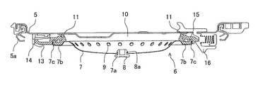
図1は本発明の実施の形態に係る炊飯器の外観を示す斜視図、図2は図1の炊飯器において蓋体を開けた状態を示す斜視図、図3は図1に示す矢視の方向から見た炊飯器の断面図である。
本実施の形態に係る炊飯器1は、図1および図2に示すように、内釜3が取り出し自在に収容される炊飯器本体2と、炊飯器本体2に開閉自在に設けられた蓋体4と、蓋体4の内側に着脱自在に設けられ、内釜3の開口を閉塞する内蓋5と、内蓋5の表面に設けられた支持体14、16に着脱自在に係止されたおねば受容器6とを備えている。炊飯器本体2の前面には、蓋体4を開閉する蓋開閉ボタン2aが設けられている。
1 is a perspective view showing the appearance of a rice cooker according to an embodiment of the present invention, FIG. 2 is a perspective view showing the rice cooker of FIG. 1 with a lid opened, and FIG. 3 is an arrow view shown in FIG. It is sectional drawing of the rice cooker seen from the direction.
As shown in FIGS. 1 and 2, the rice cooker 1 according to the present embodiment has a rice cooker
おねば受容器6は、後述するが、底部の中央に上下動自在の弁8および弁8を中心として周方向に設けられた複数のおねば分離穴9を有する深皿形状のおねば溜部7と、一端が内蓋5の表面に密接し、他端がおねば溜部7により覆われたリング状のシール部材10とを有している。
Although the
内釜3の上部外周面には、内釜3と一体に成型されたリング形状の鍔部3aが設けられている。内蓋5の周縁部には、例えばシリコンゴムにより形成されたリング状のパッキン5aが取り付けられている。この内蓋5は、蓋体4が閉じられた際に、内釜3の開口の周縁部にパッキン5aが当接して内釜3の開口を密閉状態で閉塞する。
A ring-
炊飯器本体2の内部には、図3に示すように、筒状に形成された伝熱板21と、その伝熱板21の下に設置されたほぼ深皿形状のコイル台22とが設けられている。伝熱板21の外周面には、胴ヒーター23が密着して取り付けられている。この胴ヒーター23は、炊飯時および保温時に通電されて発熱する。伝熱板21は、胴ヒーター23の熱を内釜3に伝える。なお、胴ヒーター23に代えて、誘導加熱コイルを伝熱板21の外周面に設けてもよい。
Inside the
また、コイル台22の外面(底部およびコーナー部)には、誘導加熱コイル24が巻き付けられて固定されている。誘導加熱コイル24は、通電により交番磁界を発生し、内釜3を電磁誘導により加熱する。また、コイル台22の中心部には、内釜3の底部に当接して内釜3の温度を検知する温度センサー25が設けられている。
Moreover, the
炊飯器本体2の後部側の内部には、電源基板26が設置されている。電源基板26は、半田面(裏面)側に設置された基板ホルダー26aに固定されている。電源基板26は、誘導加熱コイル24に電力を供給するスイッチング素子、その他の電子部品等が実装されている。また、前述の電源基板26には、スイッチング素子に当接された放熱器27が取り付けられている。放熱器27は、一定の間隔で整列された複数の放熱フィンを有し、熱伝導性のよいアルミニウム合金により形成されている。放熱器27の下側には、冷却ファン28が設置されている。
A
蓋体4の内側には、操作基板29が取り付けられている。操作基板29には、胴ヒーター23および誘導加熱コイル24への通電を制御する制御部を包含するマイコン(図示せず)、その他の電子部品等が実装されている。また、蓋体4の操作基板29上の位置に、メニュー選択スイッチ、炊飯スイッチ、液晶表示部30の表示窓等を備える操作パネル31が設けられている。また、蓋体4の内側には、おねば受容器6と連通する蒸気案内部32が設けられており、蓋体4の上部には、蒸気案内部32に案内された蒸気を外部へ放出する蒸気口33が設けられている。
An
次に、おねば受容器6の構成について、図4および図5を用いて説明する。
図4は図3に示す内蓋およびおねば受容器を拡大して示す断面図、図5は図4のおねば受容器を拡大して示す断面図である。
Next, the configuration of the
FIG. 4 is an enlarged sectional view showing the inner lid and the toner receiver shown in FIG. 3, and FIG. 5 is an enlarged sectional view showing the magnetic receiver shown in FIG.
図4および図5において、おねば受容器6は、前述したように、おねば溜部7と、一端が内蓋5の表面に密接し、他端がおねば溜部7により覆われたリング状のシール部材10と、係合部13、15とを有している。おねば溜部7は、例えば板金により深皿形状に形成され、その底部の中央に設けられた穴7aに上下動自在の弁8が挿入されている。この弁8は、内釜3内の圧力が沸騰により上昇した際に上方に移動して穴7aを閉塞し、内釜3内の圧力が低下したときには下方へ下がって、その穴7aを開放すると共に、おねば戻し穴8aを開放する。
In FIGS. 4 and 5, as described above, the
また、おねば溜部7には、弁8を中心として周方向に複数のおねば分離穴9が設けられている。おねば分離穴9は、内釜3内の炊飯物の沸騰時に発生する蒸気が流入した際に、蒸気に含まれるおねばを分離する。おねば分離穴9により分離されたおねばは、おねば溜部7の底部に流れて貯留される。
Further, the
おねば溜部7は、周縁部7bの先端全周に内蓋5側に延びて形成された立ち上げ縁部7cを有している。周縁部7bは、おねば溜部7を内蓋5側から見た場合、立ち上げ縁部7cによりリング状の凹みとなっている。
The
シール部材10は、例えば耐熱性・弾性を有するシリコンゴムにより形成されており、一端が外方へ湾曲して内蓋5の表面に密接し、他端がおねば溜部7により覆われている。また、シール部材10には、外周面全周に外方へ突出して設けられた縁部11および縁部11の先端全周に内蓋5側に突出する突部11aが設けられている。縁部11は、突部11aにリング状の凹み11bが形成されている。この凹み11bは、おねば溜部7の周縁部7b内に嵌め込まれている。
The
係合部13、15は、内蓋5の表面に設けられた支持体14、16に取り外し自在に係止される(図4参照)。係合部13、15のうち一方の係合部13には、シール部材10の縁部11に形成された凹み11bに嵌合する突部13a、13bが設けられている。また、その係合部13の突部13aよりも外側にシール部材10の突部11aとおねば溜部7の立ち上げ縁部7cとが嵌合する溝部13cが形成されている。
The
もう一方の係合部15には、係合部13と同様に、シール部材10の縁部11に形成された凹み11bに嵌合する突部15a、15bが設けられている。また、その係合部15の突部15aよりも外側にシール部材10の突部11aとおねば溜部7の立ち上げ縁部7cとが嵌合する溝部15cが形成されている。シール部材10の縁部11は、凹み11bに嵌合された係合部13、15の突部13a、13b・15a、15bとおねば溜部7の周縁部7bとによって挟まれて固定されている。この固定は、係合部13の溝部13cと係合部15の溝部15cにそれぞれ嵌合したシール部材10の突部11aとおねば溜部7の立ち上げ縁部7cとによって固定されている。
Similar to the
おねば受容器6を内蓋5の表面に装着する場合、前述のように、シール部材10とおねば溜部7とが固定された係合部13、15のうち、一方の係合部13を支持体14に挿入した後に、もう一方の係合部15を内蓋5側に押して支持体16に係止させて、おねば受容器6を内蓋5の表面に装着する。この装着により、シール部材10の外方へ湾曲した一端が内蓋5に密接する。
When mounting the
以上のように本実施の形態においては、内蓋5の表面に密接しているシール部材10の一端が外方へ湾曲しているので、炊飯時に内釜3内の圧力が上がった場合でも、シール部材10の外周からのおねばの浸入を防止できる。
As described above, in the present embodiment, since one end of the
また、シール部材10の縁部11が、シール部材10の凹み11bに嵌合された係合部13、15の突部13a、13b・15a、15bとおねば溜部7の周縁部7bとによって挟まれて固定されている。これにより、おねば受容器6を内蓋5に装着される前において、シール部材10を引っ張っても外れるということがない。
Further, the
なお、本実施の形態では、係合部13の溝部13cと係合部15の溝部15cにそれぞれシール部材10の突部11aとおねば溜部7の立ち上げ縁部7cとを嵌合させる構成としたが、図6に示すように、シール部材10の突部11aとおねば溜部7の立ち上げ縁部7cとを別の溝部に嵌め込むようにしても良い。
図6は図5のおねば受容器の変形例を示す断面図である。なお、図5と同様の部分には同じ符号を付している。
In the present embodiment, the
FIG. 6 is a cross-sectional view showing a modification of the nozzle of FIG. The same parts as in FIG. 5 are denoted by the same reference numerals.
係合部17、18は、係合部13、15と同様に、内蓋5の表面に設けられた支持体14、16に取り外し自在に係止される(図4参照)。係合部17、18のうち一方の係合部17には、シール部材10の縁部11に形成された凹み11bに嵌合する突部17bと、おねば溜部7の周縁部7b側に突出する隔壁部17aとが設けられている。また、係合部17には、その隔壁部17aにより内溝部17dと外溝部17cとが形成されている。内溝部17dには、シール部材10の突部11aが嵌合し、外溝部17cには、おねば溜部7の立ち上げ縁部7cが嵌合されている。
The engaging
もう一方の係合部18には、シール部材10の縁部11に形成された凹み11bに嵌合する突部18bと、おねば溜部7の周縁部7b側に突出する隔壁部18aとが設けられている。また、係合部18には、その隔壁部18aにより内溝部18dと外溝部18cとが形成されている。内溝部18dには、シール部材10の突部11aが嵌合し、外溝部18cには、おねば溜部7の立ち上げ縁部7cが嵌合されている。
The other engaging portion 18 includes a
このように、係合部17、18の内溝部17d、18dにシール部材10の突部11aを嵌合して、シール部材10を係合部17、18に取り付け、係合部17、18の外溝部17c、18cにおねば溜部7の立ち上げ縁部7cを嵌合して、おねば溜部7を係合部17、18に取り付けている。この構成により、おねば受容器6のシール部材10とおねば溜部7の係合部17、18への取り付けが容易となり、作業性が向上する。
Thus, the
1 炊飯器、2 炊飯器本体、2a 蓋開閉ボタン、3 内釜、3a 鍔部、4 蓋体、5 内蓋、5a パッキン、6 おねば受容器、7 おねば溜部、7a 穴、7b 周縁部、7c 立ち上げ縁部、8 弁、8a おねば戻し穴、9 おねば分離穴、10 シール部材、11 縁部、11a 突部、11b 凹み、13 係合部、13a、13b 突部、13c 溝部、14 支持体、15 係合部、15a、15b 突部、15c 溝部、16 支持体、17 係合部、17a 隔壁部、17b 突部、17c 外溝部、17d 内溝部、18 係合部、18a 隔壁部、18b 突部、18c 外溝部、18d 内溝部、21 遮熱板、22 コイル台、23 胴ヒーター、24 誘導加熱コイル、25 温度センサー、26 電源基板、26a 基板ホルダー、27 放熱器、28 冷却ファン、29 操作基板、30 液晶表示部、31 操作パネル、32 蒸気案内部、33 蒸気口。
1 rice cooker, 2 rice cooker body, 2a lid opening / closing button, 3 inner pot, 3a pot, 3 lid, 4 lid, 5 inner lid, 5a packing, 6 nozzle receptacle, 7 nozzle reservoir, 7a hole, 7b rim Part, 7c Rising edge part, 8 valve, 8a Sticky return hole, 9 Sticky separation hole, 10 Seal member, 11 edge part, 11a projected part, 11b recessed part, 13 engaging part, 13a, 13b projected part, 13c Grooves, 14 supports, 15 engagement parts, 15a, 15b projections, 15c groove parts, 16 supports, 17 engagement parts, 17a partition parts, 17b projections, 17c outer groove parts, 17d inner groove parts, 18 engagement parts, 18a
Claims (4)
前記蓋体の内側に設けられ、内釜の開口を閉塞する内蓋と、
前記内蓋の表面に着脱自在に接して装着されたおねば受容器と
を備え、
前記おねば受容器は、
底部の中央に上下動自在の弁および当該弁を中心として周方向に設けられた複数のおねば分離穴を有するおねば溜部と、
一端が前記内蓋の表面に接し、他端が前記おねば溜部により覆われたシール部材とを有し、
前記シール部材の一端は、外方へ湾曲していることを特徴とする炊飯器。 With a lid ,
An inner lid provided inside the lid and closing an opening of the inner hook;
And a toner receiver detachably mounted on the surface of the inner lid,
The toner receptor is
A valve having a vertically movable valve at the center of the bottom and a nozzle reservoir having a plurality of nozzle separation holes provided circumferentially about the valve;
And a seal member having one end in contact with the surface of the inner lid and the other end covered by the nozzle reservoir,
One end of the said sealing member is curving outward, The rice cooker characterized by the above-mentioned.
前記おねば溜部は、周縁部の先端全周に前記内蓋側に延びて形成された立ち上げ縁部を有し、
前記おねば受容器は、前記シール部材の突部および前記おねば溜部の立ち上げ縁部が嵌合される係合部を備えていることを特徴とする請求項1記載の炊飯器。 The seal member has an edge provided to project outward around the entire outer peripheral surface, and a projection that projects toward the inner lid on the entire front end of the edge.
The nozzle reservoir has a rising edge formed extending to the inner lid side around the entire tip of the peripheral edge,
The rice cooker according to claim 1, wherein the nozzle receiver comprises an engagement portion into which the projection of the seal member and the rising edge portion of the nozzle reservoir are fitted.
前記シール部材の縁部は、前記シール部材の突部により凹みが形成され、当該凹み内に前記係合部の突部が嵌合されて、当該係合部の突部と前記おねば溜部の周縁部とに狭持されて固定されていることを特徴とする請求項2記載の炊飯器。 The engagement portion has a protrusion,
The edge of the seal member is formed with a recess by the protrusion of the seal member, and the protrusion of the engagement portion is fitted in the recess, and the protrusion of the engagement portion and the toner storage portion The rice cooker according to claim 2, characterized in that it is pinched and fixed to the peripheral portion of the rice bowl.
Priority Applications (2)
| Application Number | Priority Date | Filing Date | Title |
|---|---|---|---|
| JP2016037179A JP6523993B2 (en) | 2016-02-29 | 2016-02-29 | rice cooker |
| CN201611178363.XA CN107126089B (en) | 2016-02-29 | 2016-12-19 | Cooker |
Applications Claiming Priority (1)
| Application Number | Priority Date | Filing Date | Title |
|---|---|---|---|
| JP2016037179A JP6523993B2 (en) | 2016-02-29 | 2016-02-29 | rice cooker |
Publications (3)
| Publication Number | Publication Date |
|---|---|
| JP2017153544A JP2017153544A (en) | 2017-09-07 |
| JP2017153544A5 JP2017153544A5 (en) | 2018-08-09 |
| JP6523993B2 true JP6523993B2 (en) | 2019-06-05 |
Family
ID=59721870
Family Applications (1)
| Application Number | Title | Priority Date | Filing Date |
|---|---|---|---|
| JP2016037179A Active JP6523993B2 (en) | 2016-02-29 | 2016-02-29 | rice cooker |
Country Status (2)
| Country | Link |
|---|---|
| JP (1) | JP6523993B2 (en) |
| CN (1) | CN107126089B (en) |
Families Citing this family (2)
| Publication number | Priority date | Publication date | Assignee | Title |
|---|---|---|---|---|
| EP3666062B1 (en) | 2017-08-08 | 2022-07-13 | AGC Green-Tech Co., Ltd. | Plant cultivation method and plant cultivation device |
| CN108903600A (en) * | 2018-08-29 | 2018-11-30 | 九阳股份有限公司 | The cooking apparatus conveniently uncapped |
Family Cites Families (19)
| Publication number | Priority date | Publication date | Assignee | Title |
|---|---|---|---|---|
| JPS5931318U (en) * | 1982-08-19 | 1984-02-27 | 三菱電機株式会社 | Jiya rice cooker |
| JPS5977923U (en) * | 1982-11-16 | 1984-05-26 | 三洋電機株式会社 | Heat-retaining rice cooker |
| JPS5995929U (en) * | 1983-11-15 | 1984-06-29 | 三洋電機株式会社 | Heat-retaining rice cooker |
| JPS60140523U (en) * | 1984-02-28 | 1985-09-18 | 三洋電機株式会社 | Heat-retaining rice cooker |
| JPH09262175A (en) * | 1996-03-29 | 1997-10-07 | Toshiba Home Technol Corp | Rice cooker |
| JP3440463B2 (en) * | 1997-04-25 | 2003-08-25 | 東芝ホームテクノ株式会社 | Insulated pot |
| JP3437464B2 (en) * | 1998-09-30 | 2003-08-18 | 三菱電機株式会社 | rice cooker |
| JP3922836B2 (en) * | 1999-06-29 | 2007-05-30 | 大阪瓦斯株式会社 | Combustion rice cooker |
| TW502601U (en) * | 1999-07-13 | 2002-09-11 | Mitsubishi Electric Corp | Rice cooker |
| JP4044016B2 (en) * | 2003-08-08 | 2008-02-06 | 象印マホービン株式会社 | Packing structure of pressure rice cooker |
| JP3976028B2 (en) * | 2004-04-08 | 2007-09-12 | タイガー魔法瓶株式会社 | Electric rice cooker |
| JP4476306B2 (en) * | 2007-02-15 | 2010-06-09 | 三洋電機株式会社 | Pressure cooker |
| JP4941899B2 (en) * | 2008-03-31 | 2012-05-30 | 東芝ホームテクノ株式会社 | rice cooker |
| JP4961387B2 (en) * | 2008-05-30 | 2012-06-27 | 日立アプライアンス株式会社 | rice cooker |
| JP4684329B2 (en) * | 2008-12-26 | 2011-05-18 | 三洋電機株式会社 | Electric rice cooker and rice cooking method |
| JP5501274B2 (en) * | 2011-03-10 | 2014-05-21 | 日立アプライアンス株式会社 | rice cooker |
| KR101265106B1 (en) * | 2012-02-07 | 2013-05-16 | 김차식 | Electric cooker |
| CN203399959U (en) * | 2013-06-08 | 2014-01-22 | 广东伊立浦电器股份有限公司 | Electric rice cooker with normally closed valve |
| CN108135383B (en) * | 2015-10-30 | 2020-08-07 | 三菱电机株式会社 | Electric rice cooker |
-
2016
- 2016-02-29 JP JP2016037179A patent/JP6523993B2/en active Active
- 2016-12-19 CN CN201611178363.XA patent/CN107126089B/en active Active
Also Published As
| Publication number | Publication date |
|---|---|
| JP2017153544A (en) | 2017-09-07 |
| CN107126089A (en) | 2017-09-05 |
| CN107126089B (en) | 2019-06-25 |
Similar Documents
| Publication | Publication Date | Title |
|---|---|---|
| KR101911476B1 (en) | Cover body assembly for electric cooker and electric cooker having same | |
| JP6523993B2 (en) | rice cooker | |
| JP2008167890A (en) | Rice cooker | |
| JP6552630B2 (en) | rice cooker | |
| JP3572361B2 (en) | rice cooker | |
| CN108135381B (en) | Rice cooker | |
| JP6448372B2 (en) | rice cooker | |
| JP3498699B2 (en) | rice cooker | |
| TWI623291B (en) | Rice cooker | |
| JP2009225926A (en) | Rice cooker | |
| JP2009233230A (en) | Rice cooker | |
| JP2713129B2 (en) | Electric rice cooker | |
| KR101454796B1 (en) | Sepetated pressure cooker from base housing | |
| JP2000041836A (en) | Rice cooker | |
| JP2715880B2 (en) | Electric rice cooker | |
| JP6045135B2 (en) | rice cooker | |
| JP3132429B2 (en) | Electric rice cooker | |
| JPH1156613A (en) | Rice cooker | |
| KR20180060656A (en) | Electric pressure cooker | |
| JP5332844B2 (en) | rice cooker | |
| JP6624971B2 (en) | rice cooker | |
| JP2008259717A (en) | Electric rice cooker | |
| JP2004160184A (en) | Rice cooker | |
| JPH0423466Y2 (en) | ||
| KR102426297B1 (en) | Electric pressure cooker |
Legal Events
| Date | Code | Title | Description |
|---|---|---|---|
| A521 | Request for written amendment filed |
Free format text: JAPANESE INTERMEDIATE CODE: A523 Effective date: 20180625 |
|
| A621 | Written request for application examination |
Free format text: JAPANESE INTERMEDIATE CODE: A621 Effective date: 20180625 |
|
| A977 | Report on retrieval |
Free format text: JAPANESE INTERMEDIATE CODE: A971007 Effective date: 20190308 |
|
| TRDD | Decision of grant or rejection written | ||
| A01 | Written decision to grant a patent or to grant a registration (utility model) |
Free format text: JAPANESE INTERMEDIATE CODE: A01 Effective date: 20190402 |
|
| A61 | First payment of annual fees (during grant procedure) |
Free format text: JAPANESE INTERMEDIATE CODE: A61 Effective date: 20190426 |
|
| R150 | Certificate of patent or registration of utility model |
Ref document number: 6523993 Country of ref document: JP Free format text: JAPANESE INTERMEDIATE CODE: R150 |
|
| R250 | Receipt of annual fees |
Free format text: JAPANESE INTERMEDIATE CODE: R250 |
|
| R250 | Receipt of annual fees |
Free format text: JAPANESE INTERMEDIATE CODE: R250 |
|
| R250 | Receipt of annual fees |
Free format text: JAPANESE INTERMEDIATE CODE: R250 |