JP6523940B2 - Thermal power plant and method of operating the same - Google Patents
Thermal power plant and method of operating the same Download PDFInfo
- Publication number
- JP6523940B2 JP6523940B2 JP2015243550A JP2015243550A JP6523940B2 JP 6523940 B2 JP6523940 B2 JP 6523940B2 JP 2015243550 A JP2015243550 A JP 2015243550A JP 2015243550 A JP2015243550 A JP 2015243550A JP 6523940 B2 JP6523940 B2 JP 6523940B2
- Authority
- JP
- Japan
- Prior art keywords
- opening degree
- valve body
- load
- steam
- turbine
- Prior art date
- Legal status (The legal status is an assumption and is not a legal conclusion. Google has not performed a legal analysis and makes no representation as to the accuracy of the status listed.)
- Active
Links
Images


Description
本発明の実施形態は、火力発電プラント、および、その運転方法に関する。 Embodiments of the present invention relate to a thermal power plant and a method of operating the same.
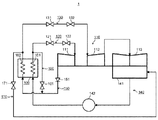
図12は、関連技術に係る火力発電プラントの概要を模式的に系統図である。 FIG. 12 is a schematic diagram schematically showing a thermal power plant according to a related art.
図12に示すように、火力発電プラント1において、ボイラ100は、蒸気発生器101と再熱器102とを有する。蒸気タービン部110は、高圧タービン111と中圧タービン112と低圧タービン113とを有する。主蒸気系120は、主蒸気止め弁121と蒸気加減弁122(流量制御弁)とを有する。再熱蒸気系130は、再熱蒸気止め弁131とインターセプト弁132とを有する。復水給水系140は、復水器141と給水ポンプ142とを有する。低温再熱系150は、逆止弁151を有する。高圧タービンバイパス系160は、高圧タービンバイパス弁161を有する。低圧タービンバイパス系170は、低圧タービンバイパス弁171を有する。
As shown in FIG. 12, in the
火力発電プラント1では、ボイラ100の蒸気発生器101が主蒸気を発生し、その主蒸気が主蒸気系120(主蒸気管)を流れる。主蒸気は、主蒸気止め弁121および蒸気加減弁122を介して、高圧タービン111に作動流体として供給される。そして、主蒸気は、高圧タービン111において膨張して仕事を行い、高圧タービン111から排気蒸気として排出される。高圧タービン111から排気された排気蒸気は、低温再熱系150(低温再熱管)を流れる。その排気蒸気は、逆止弁151を介して、ボイラ100の再熱器102に流れ、再熱器102で再熱される。再熱器102で再熱された蒸気は、再熱蒸気として再熱蒸気系130(再熱蒸気管)を流れる。再熱蒸気は、再熱蒸気止め弁131およびインターセプト弁132を介して、中圧タービン112に作動流体として供給される。そして、再熱蒸気は、中圧タービン112において膨張して仕事を行った後に、低圧タービン113において膨張して仕事を行う。低圧タービン113から排出された排気蒸気は、復水器141で凝縮されて復水になり、給水ポンプ142に供給される。そして、その復水は、給水ポンプ142において加圧され、蒸気発生器101に給水として供給される。給水ポンプ142で加圧された給水は、蒸気発生器101において加熱され、上述したように、主蒸気として高圧タービン111に供給される。火力発電プラント1では、高圧タービン111と中圧タービン112と低圧タービン113とのそれぞれは、回転軸が連結されており、回転軸の回転によって発電機(図示省略)が駆動するように構成されている。
In the
低圧タービンバイパス系170は、再熱蒸気系130において再熱蒸気止め弁131よりも上流側に位置する分岐点に配管の一端が接続されていると共に、配管の他端が復水器141に接続されている。低圧タービンバイパス系170においては、たとえば、再熱蒸気の圧力と温度との少なくとも一方が予め定められた値に達していないときに、その再熱蒸気が低圧タービンバイパス弁171を介して復水器141に流れる。
In the low-pressure
高圧タービンバイパス系160は、主蒸気系120において主蒸気止め弁121よりも上流側に位置する分岐点に配管の一端が接続されていると共に、配管の他端が低温再熱系150に接続されている。高圧タービンバイパス系160においては、たとえば、主蒸気の圧力と温度との少なくとも一方が予め定められた値に達していないときに、その主蒸気が高圧タービンバイパス弁161を介して低温再熱系150と低圧タービンバイパス系170とを順次流れた後に、復水器141に流れる。この他に、負荷遮断などのように異常事態が発生して主蒸気の流量が過剰になった場合に、主蒸気が各部を経由して復水器141に流れる。
In the high-pressure
上記の火力発電プラント1においては、タービン調速方法として、絞り調速方式(全周噴射方式)とノズル締切調速方式(部分噴射方式)との二つの方式が代表的に広く採用されている。
In the
まず、絞り調速方式の具体的内容について説明する。 First, the specific content of the aperture control system will be described.
図13,図14,図15は、関連技術に係る火力発電プラントにおいて、タービン調速方法として、絞り調速方式を説明するための図である。 FIG.13, FIG.14, FIG.15 is a figure for demonstrating the throttling control system as a turbine control method in the thermal-power-generation plant which concerns on related technology.
図13は、関連技術に係る火力発電プラント1(図12参照)において、高圧タービン111と蒸気加減弁122とが設けられた部分の概要を模式的に示す図である。ここでは、蒸気加減弁122が2つの弁体を有する場合について示している。
FIG. 13 is a view schematically showing an outline of a portion where the high pressure turbine 111 and the
図14は、関連技術に係る火力発電プラント1において、蒸気加減弁122の動作を制御する制御装置400の概要を示すブロック図である。
FIG. 14 is a block diagram showing an outline of a
図15は、関連技術に係る火力発電プラント1において、蒸気加減弁122を構成する複数の弁体の開度を示すグラフ(弁開度特性)である。図15においては、横軸がタービン負荷TL(%)(要求蒸気流量)を示し、縦軸が蒸気加減弁122を構成する複数の弁体の開度K(%)を示している。タービン負荷TLは、定格負荷を100%とした場合の割合を示す。また、弁体の開度Kは、全開状態を100%とした場合の割合を示している。それぞれについて、以降、%の表示を省略する。
FIG. 15 is a graph (valve opening degree characteristic) showing the opening degree of a plurality of valve bodies constituting the
図13に示すように、高圧タービン111においては、蒸気室20から作動蒸気が供給された後に、複数段のタービン段落21(第1段タービン段落21a,第2段タービン段落21b)に供給され、タービンロータ(図示省略)が回転する。図示を省略しているが、複数段のタービン段落21は、タービンロータの回転軸に沿った軸方向に配列されている。複数段のタービン段落21のそれぞれは、ノズル部211(静翼部)と動翼部212とを有する。図示を省略しているが、ノズル部211においては、複数の静翼(図示省略)が回転方向に配列されており、動翼部212においては、複数の動翼(図示省略)が回転方向に配列されている。
As shown in FIG. 13, in the high pressure turbine 111, after the working steam is supplied from the
図13に示すように、蒸気加減弁122は、複数の弁体31を有する。ここでは、蒸気加減弁122は、複数の弁体31として、第1弁体31aと第2弁体31bとが設けられている。蒸気加減弁122は、弁ケーシング(図示省略)の内部において、第1弁体31aの移動により開度を調整すると共に、第2弁体31bの移動により開度を調整することによって、主蒸気の流量を調整する。
As shown in FIG. 13, the
図14に示すように、制御装置400は、速度制御回路401と負荷制御回路402と加減算器403と演算信号分配器404と第1関数器405aと第2関数器405bとを有する。制御装置400の各部は、たとえば、メモリ装置が記憶しているプログラムを用いて演算器が演算処理を行うように構成されており、第1弁体31aの開度と第2弁体31bの開度とのそれぞれを制御する。
As shown in FIG. 14, the
制御装置400においては、速度制御回路401がタービン回転数制御信号S401を加減算器403に出力し、負荷制御回路402がタービン負荷設定信号S402を加減算器403に出力する。加減算器403は、タービン回転数制御信号S401とタービン負荷設定信号S402とを突き合わせた結果に応じて、タービン回転数制御信号S401とタービン負荷設定信号S402との間において加算処理または減算処理を行うことで、加減算演算信号S403を求め、演算信号分配器404に出力する。演算信号分配器404は、その加減算演算信号S403をタービン負荷信号S404(流量要求信号)として第1関数器405aと第2関数器405bとのそれぞれに分配する。
In the
第1関数器405aは、第1の関数K405aを記憶しており、その第1の関数K405aを用いて、タービン負荷信号S404に応じた第1の弁開度演算信号S405a(第1弁リフト信号)を演算する。第1の関数K405aは、タービン負荷信号S404を入力信号(独立変数)とし、第1の弁開度演算信号S405aを出力信号(従属変数)とした関数である。
The
同様に、第2関数器405bは、予め記憶された第2の関数K405bを用いて、タービン負荷信号S404に応じた第2の弁開度演算信号S405b(第2弁リフト信号)を演算し出力する。
Similarly, the
絞り調速方式においては、第1の弁開度演算信号S405aの信号値および第2の弁開度演算信号S405bの信号値の両者は、タービン負荷信号S404の信号値に対して、同じ割合で増加する。 In the throttle control system, both the signal value of the first valve opening calculation signal S405a and the signal value of the second valve opening calculation signal S405b are at the same ratio to the signal value of the turbine load signal S404. To increase.
第1の弁開度演算信号S405aは、第1弁体31aを駆動する駆動装置(図示省略)に出力され、第1弁体31aの開度が第1の弁開度演算信号S405aに応じた開度に調整される。第2の弁開度演算信号S405bは、第2弁体31bを駆動する駆動装置(図示省略)に出力され、第2弁体31bの開度が第2の弁開度演算信号S405bに応じた開度に調整される。
The first valve opening degree calculation signal S405a is output to a drive (not shown) for driving the
このため、絞り調速方式においては、図13および図15に示すように、タービン負荷TL(タービン負荷信号S404の信号値)に応じて、第1弁体31aの開度Kと第2弁体31bの開度Kとが互いに同じになるように、制御される。したがって、絞り調速方式では、複数の蒸気入口管のそれぞれに主蒸気が均一に割り振られるので、蒸気室20の内部においては温度差が生じない。
For this reason, in the throttle control system, as shown in FIGS. 13 and 15, the opening degree K of the
しかしながら、定格負荷運転でなく、部分負荷運転が行われる場合には、複数の弁体31(第1弁体31a,第2弁体31b)の開度Kのそれぞれが全開状態よりも小さい開度に絞られた弁体を含む。このため、蒸気加減弁122において、絞り損失が発生する。その結果、絞り調速方式で部分負荷運転を行う場合には、タービン内部効率が低下する。
However, when partial load operation is performed instead of rated load operation, each of the opening degrees K of the plurality of valve bodies 31 (the
つぎに、図16,図17,図18を用いてタービン調速方法としてノズル締切調速方式を説明する。 Next, a nozzle shutoff speed control system will be described as a turbine speed control method with reference to FIGS. 16, 17 and 18.
ノズル締切調速方式においては、蒸気室20は、図16に示すように、絞り調速方式の場合(図13参照)と異なり、仕切り(図示省略)によって、第1蒸気室部201と第2蒸気室部202とに区画されている。そして、第1蒸気室部201は、第1弁体31aが開けられることで主蒸気が流れ、第2蒸気室部202は、第2弁体31bが開けられることで主蒸気が流れる。ノズル締切調速方式では、第1段タービン段落21aのノズル部211は、調速段と呼ばれており、第1蒸気室部201に連通する調速段を通過した蒸気と第2蒸気室部202に連通する調速段を通過した蒸気とが合流し、第2段タービン段落21bへ流れる。
In the nozzle cut-off speed control system, as shown in FIG. 16, the
また、図17に示すように、ノズル締切調速方式では、第1の関数K405aおよび第2の関数K405bが、絞り調速方式の場合(図14参照)と異なっている。 Further, as shown in FIG. 17, in the nozzle shutoff speed control system, the first function K405a and the second function K405b are different from those in the aperture speed control system (see FIG. 14).
具体的には、第1の関数K405aにおいては、タービン負荷信号S404の信号値(タービン負荷TL)が0から増加するに伴って、第1の弁開度演算信号S405aの信号値が0から増加して100になる。 Specifically, in the first function K405a, as the signal value (turbine load TL) of the turbine load signal S404 increases from 0, the signal value of the first valve opening degree operation signal S405a increases from 0 It will be 100.
これに対して、第2の関数K405bにおいては、タービン負荷信号S404の信号値が0から所定値までの範囲では、第2の弁開度演算信号S405bの信号値が0である。第2の関数K405bでは、タービン負荷信号S404の信号値が所定値から増加するに伴って、第2の弁開度演算信号S405bの信号値が0から増加して100になる。 On the other hand, in the second function K405b, the signal value of the second valve opening degree operation signal S405b is 0 when the signal value of the turbine load signal S404 is in the range from 0 to a predetermined value. In the second function K405b, as the signal value of the turbine load signal S404 increases from the predetermined value, the signal value of the second valve opening degree operation signal S405b increases from 0 to 100.
このため、ノズル締切調速方式においては、図18に示すように、タービン負荷TLに応じて、第1弁体31aの開度Kが第2弁体31bの開度Kよりも先に大きくなる。そして、第1弁体31aの開度Kが全開状態になった後に、第2弁体31bの開度Kが大きくなって全開状態になる。したがって、部分負荷運転の際には、第1弁体31aが全開状態である時間が、絞り調速方式の場合よりも長くなるので、絞り損失が小さく、タービン内部効率が大きい。
Therefore, in the nozzle shutoff speed control system, as shown in FIG. 18, the opening degree K of the
しかしながら、蒸気室20が仕切りで第1蒸気室部201と第2蒸気室部202とに区画されているので、定格負荷運転の際には、蒸気室20において周方向の流れが阻害される。その結果、ノズル締切調速方式で定格負荷運転を行う際には、タービン内部効率が低下する。
However, since the
さらに、火力発電プラント1においては、ボイラ100が発生する主蒸気の圧力を制御する圧力制御方式として、定圧方式と変圧方式との二つの方式がある。
Furthermore, in the
図19は、関連技術において、圧力制御方式(定圧方式,変圧方式)を説明するための図である。図19において、縦軸は、ボイラ100が発生する主蒸気の圧力Pを示しており、横軸は、タービン負荷TLを示している。
FIG. 19 is a diagram for explaining a pressure control method (constant pressure method, transformation method) in the related art. In FIG. 19, the vertical axis represents the pressure P of the main steam generated by the
定圧方式は、タービン負荷TLの増加に関わらずに、主蒸気の圧力Pを一定に保持させる圧力制御方式である。たとえば、図19の線DR1で示すように、定圧方式では、タービン負荷TLが0から100(定格負荷)までの範囲において、主蒸気の圧力Pが第2の圧力P2で一定になるように、ボイラ100の動作が制御される。この他に、図19の線DR2で示すように、定圧方式では、タービン負荷TLが0から100より小さい所定値TL1までの範囲において、主蒸気の圧力Pが第1の圧力P1で一定になるように、ボイラ100の動作が制御される。定圧方式においては、蒸気加減弁122の絞り損失が大きい。
The constant pressure system is a pressure control system that keeps the pressure P of the main steam constant regardless of the increase of the turbine load TL. For example, as shown by line DR1 in FIG. 19, in the constant pressure system, the pressure P of the main steam is constant at the second pressure P2 in the range of 0 to 100 (rated load) of the turbine load TL. The operation of the
これに対して、変圧方式は、タービン負荷TLがある一定値以上になると、タービン負荷の増加に伴って主蒸気の圧力Pを増加させる圧力制御方式である。たとえば、図19の線DR2で示すように、変圧方式では、タービン負荷TLが所定値TL1から100までの範囲において、主蒸気の圧力Pが第1の圧力P1から第2の圧力P2に増加するように、ボイラ100の動作が制御される。変圧方式においては、蒸気加減弁122の絞り損失が定圧方式よりも小さい。
On the other hand, the transformation method is a pressure control method in which the pressure P of the main steam is increased as the turbine load increases when the turbine load TL exceeds a certain value. For example, as shown by line DR2 in FIG. 19, in the transformation system, the pressure P of the main steam increases from the first pressure P1 to the second pressure P2 in the range of the turbine load TL from the predetermined value TL1 to 100. As such, the operation of the
火力発電プラントは、発電効率の向上が求められている。このため、上記したタービン調速方法、および、圧力制御方式を適宜組み合わせて、火力発電プラント1の運転を行うことが提案されている。その組合せの一例を、図20以降の図を用いて説明する。
Thermal power plants are required to improve power generation efficiency. Therefore, it has been proposed that the
図20では、蒸気室20に関して、タービンロータ(図示省略)の回転軸が沿った軸方向に対して直交する面を示している。
In FIG. 20, a plane orthogonal to the axial direction along the rotation axis of the turbine rotor (not shown) is shown with respect to the
本関連技術では、蒸気室20は、仕切り20pによって第1蒸気室部201と第2蒸気室部202とに区画されている。第1蒸気室部201は、第1弁体31aが開けられることで主蒸気が流れ、第2蒸気室部202は、第2弁体31bが開けられることで主蒸気が流れる。ここでは、第1蒸気室部201から第1段タービン段落21aへ主蒸気が流れる流路の第1段ノズル面積と、第2蒸気室部202から第1段タービン段落21aへ主蒸気が流れる流路の第1段ノズル面積とが、互いに同じになるように構成されている(図16参照)。
In the related art, the
図21に示すように、本関連技術では、ボイラ100(図12参照)は、タービン負荷TLに応じて、定圧方式CD1,CD2と変圧方式VDとを切り替えるように制御される。図示を省略しているが、ボイラ100の動作は、蒸気加減弁122と同様に、制御装置400がタービン負荷TLに応じて制御する。
As shown in FIG. 21, in the related art, the boiler 100 (see FIG. 12) is controlled to switch between the constant pressure method CD1 and CD2 and the transformation method VD according to the turbine load TL. Although illustration is omitted, the operation of the
具体的には、タービン負荷TLが0からL11(たとえば、L11=30%)までの範囲においては、定圧方式CD1(第1の定圧方式)で運転を行う。タービン負荷TLがL11からL12(L12>L11,たとえば、L12=70%)までの範囲においては、変圧方式VDで運転を行う。タービン負荷TLがL12から100までの範囲においては、定圧方式CD2(第2の定圧方式)で運転を行う。 Specifically, in the range from 0 to L11 (for example, L11 = 30%) of the turbine load TL, the operation is performed by the constant pressure method CD1 (first constant pressure method). When the turbine load TL is in the range from L11 to L12 (L12> L11, for example, L12 = 70%), operation is performed by the transformation type VD. When the turbine load TL is in the range from L12 to 100, operation is performed by the constant pressure method CD2 (second constant pressure method).
図22に示すように、第1の関数K405aおよび第2の関数K405bは、ノズル締切調速方式で火力発電プラントを運転するように設定されている。
As shown in FIG. 22, the
具体的には、第1の関数K405aは、タービン負荷信号S404の信号値が0からL11まで増加するに伴って、第1の弁開度演算信号S405aの信号値が0から100に増加するように設定されている。そして、第1の関数K405aは、タービン負荷信号S404の信号値がL11から100である範囲では、第1の弁開度演算信号S405aの信号値が100を保持するように設定されている。 Specifically, in the first function K405a, as the signal value of the turbine load signal S404 increases from 0 to L11, the signal value of the first valve opening degree operation signal S405a increases from 0 to 100. It is set to. The first function K405a is set so that the signal value of the first valve opening degree computing signal S405a is maintained at 100 when the signal value of the turbine load signal S404 is in the range of L11 to 100.
これに対して、第2の関数K405bは、タービン負荷信号S404の信号値が0からL12(L12>L11)である範囲では、第2の弁開度演算信号S405bの信号値が0を保持するように設定されている。そして、第2の関数K405bは、タービン負荷信号S404の信号値がL12から100に増加するに伴って、第2の弁開度演算信号S405bの信号値が0から100に増加するように設定されている。 On the other hand, in the second function K405b, the signal value of the second valve opening degree operation signal S405b holds 0 within the range where the signal value of the turbine load signal S404 is 0 to L12 (L12> L11). Is set as. Then, the second function K405b is set such that the signal value of the second valve opening degree operation signal S405b increases from 0 to 100 as the signal value of the turbine load signal S404 increases from L12 to 100. ing.
このため、本関連技術では、図21および図23に示すように、定圧方式CD1で運転を行う際には、タービン負荷TLが0からL11に増加するに伴って、第1弁体31aの開度Kが大きくなり、第1弁体31aが全閉状態(K=0)から全開状態(K=100)になる。このとき、第2弁体31bは、全閉状態(K=0)を保持する。
Therefore, in the related art, as shown in FIG. 21 and FIG. 23, when operating with the constant pressure system CD1, as the turbine load TL increases from 0 to L11, the
変圧方式VDで運転を行う際には、タービン負荷TLがL11からL12までの範囲において、第1弁体31aは、全開状態(K=100)を保持する。このとき、第2弁体31bは、上記と同様に、全閉状態(K=0)を保持する。
When operating with the transformation type VD, the
定圧方式CD2で運転を行う際には、タービン負荷TLがL12から100までの範囲において、第1弁体31aは全開状態(K=100)を保持する。これに対して、第2弁体31bは、上記と異なり、タービン負荷TLに応じて開度Kが大きくなり、全閉状態(K=0)から全開状態(K=100)になる。
When operating with the constant pressure system CD2, the
上記のように、本関連技術では、火力発電プラントの発電効率を向上するために、ノズル締切調速方式の運転において、定圧方式CD1,CD2と変圧方式VDとを組み合わせている。 As described above, in the related art, in order to improve the power generation efficiency of the thermal power plant, the constant pressure method CD1 and CD2 and the transformation method VD are combined in the operation of the nozzle cut-off speed control method.
しかしながら、本関連技術では、火力発電プラントの発電効率を十分に向上させることが容易でない。 However, in the related art, it is not easy to sufficiently improve the power generation efficiency of the thermal power plant.
具体的には、本関連技術では、定圧方式CD2で運転を行う際には、上記したように、先行弁である第1弁体31aが全開状態であるときに、後行弁である第2弁体31bの開度Kがタービン負荷TLに応じて大きくなる。このため、第2弁体31bが開いて流れる蒸気において、圧力損失が大きくなる。
Specifically, in the related art, when operating with the constant pressure method CD2, as described above, when the
この他に、定圧方式CD2で運転を行う際には、第1弁体31aが開いて第1蒸気室部201(図16参照)に流れる蒸気の流量と、第2弁体31bが開いて第2蒸気室部202(図16参照)に流れる蒸気の流量とが、互いに異なる。これにより、第1段タービン段落21aのノズル部211を通過後においては、第1蒸気室部201と第2蒸気室部202とのそれぞれから、流量が互いに異なる蒸気が合流するので、蒸気室20において周方向に蒸気が移動するときの速度エネルギーについて損失(周方向エネルギー損失)が生ずる。初段ノズルを通過する蒸気の流量が設計値から乖離した場合、ノズルの段落効率が低下する。
In addition to this, when operating with the constant pressure system CD2, the
その結果、本関連技術では、タービン内部効率(タービン調速段効率)が低下し、エネルギーを効率的に利用することが容易でない。 As a result, in the related art, the turbine internal efficiency (turbine control stage efficiency) decreases, and it is not easy to efficiently use energy.
したがって、本発明が解決しようとする課題は、タービン内部効率を向上可能な、火力発電プラント、および、その運転方法を提供することである。 Therefore, the problem to be solved by the present invention is to provide a thermal power plant and an operating method thereof capable of improving the turbine internal efficiency.
実施形態の火力発電プラントは、ボイラと蒸気タービン部と蒸気加減弁と制御装置とを有する。蒸気タービン部は、ボイラで発生した主蒸気が蒸気室に作動流体として流入する。蒸気加減弁は、ボイラから蒸気室に流れる主蒸気の流量を調整する。制御装置は、蒸気加減弁の動作をタービン負荷に応じて制御する。ここでは、蒸気加減弁は、第1弁体と第2弁体とを含む。蒸気室は、第1蒸気室部と第2蒸気室部とを含み、第1弁体が開けられることで第1蒸気室部に主蒸気が流入し、第2弁体が開けられることで第2蒸気室部に主蒸気が流入する。制御装置は、タービン負荷が第1負荷から当該第1負荷よりも大きい第2負荷までの範囲では、第1弁体の開度が全開状態を保持すると共に、第2弁体の開度がタービン負荷の増加に応じて全閉状態から第1開度になるように、蒸気加減弁の動作を制御する。制御装置は、タービン負荷が第2負荷であるときには、第1弁体の開度が全開状態から第2開度になると共に、第2弁体の開度が第1開度から第2開度になるように、蒸気加減弁の動作を制御する。制御装置は、タービン負荷が第2負荷から増加するに伴って、第1弁体および第2弁体が同じ開度で第2開度から全開状態になる部分を含むように、蒸気加減弁の動作を制御する。 The thermal power plant of the embodiment includes a boiler, a steam turbine unit, a steam control valve, and a control device. In the steam turbine unit, main steam generated in the boiler flows into the steam chamber as a working fluid. The steam control valve regulates the flow rate of the main steam flowing from the boiler to the steam chamber. The controller controls the operation of the steam control valve according to the turbine load. Here, the steam control valve includes a first valve body and a second valve body. The steam chamber includes a first steam chamber portion and a second steam chamber portion, and when the first valve body is opened, main steam flows into the first steam chamber portion, and the second valve body is opened. 2 Main steam flows into the steam chamber. The controller maintains the opening degree of the first valve body in the fully open state and the opening degree of the second valve body in the turbine load within the range from the first load to the second load greater than the first load. The operation of the steam control valve is controlled so that the first opening degree is reached from the fully closed state according to the increase of the load. When the turbine load is the second load, the controller changes the opening degree of the first valve body from the fully open state to the second opening degree, and the opening degree of the second valve body from the first opening degree to the second opening degree Control the operation of the steam control valve so that The controller controls the steam control valve to include a portion where the first valve body and the second valve body move from the second opening degree to the fully open state at the same opening degree as the turbine load increases from the second load. Control the operation.
実施形態について、図面を参照して説明する。 Embodiments will be described with reference to the drawings.
<第1実施形態>
図1,図2は、第1実施形態に係る火力発電プラントを説明するための図である。
First Embodiment
1 and 2 are views for explaining a thermal power plant according to the first embodiment.
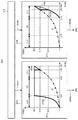
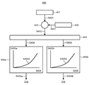
図1は、第1実施形態に係る火力発電プラントにおいて、制御装置400の概要を示すブロック図である。図1では、図22と異なり、制御装置400のうち、速度制御回路401と負荷制御回路402と加減算器403との図示を省略し、演算信号分配器404と第1関数器405aと第2関数器405bとを拡大して図示している。
FIG. 1 is a block diagram showing an outline of a
図1においては、第1関数器405aが有する第1の関数K405aと、第2関数器405bが有する第2の関数K405bとについて、本実施形態の場合に関して太い実線で示している。この他に、図1において、第1関数器405aおよび第2関数器405bには、第1弁体31aの開度と第2弁体31bの開度との両者を絞り調速方式で調整するときに用いる関数KFの一部を太い一点鎖線で併記している。また、第1関数器405aには、第1弁体31aの開度と第2弁体31bの開度との両者をノズル締切調速方式で調整する場合において、第1弁体31aの開度について調整するときに用いる関数KPaの一部を太い破線で併記している(関数KPaは、図22に示した第1の関数K405aと同じである)。また、第2関数器405bには、第1弁体31aの開度と第2弁体31bの開度との両者をノズル締切調速方式で調整する関数のうち、第2弁体31bの開度について調整するときに用いる関数KPbの一部を太い破線で併記している(関数KPbは、図22に示した第2の関数K405bと同じである)。
In FIG. 1, the
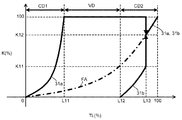
図2は、第1実施形態に係る火力発電プラントにおいて、蒸気加減弁122を構成する複数の弁体の開度を示すグラフである。図2では、図23と同様に、横軸がタービン負荷TLを示しており、縦軸が蒸気加減弁122を構成する複数の弁体の開度Kを示している。
FIG. 2 is a graph showing the opening degree of a plurality of valve bodies constituting the
図2では、第1弁体31aの開度Kと第2弁体31bの開度Kとについて、本実施形態の場合に関して太い実線で示している。この他に、図2では、第1弁体31aの開度Kと第2弁体31bの開度Kとの両者を絞り調速方式で調整する場合に関して、太い一点鎖線FAで併記している。
In FIG. 2, the opening degree K of the
本実施形態において、蒸気室20は、上記の関連技術の場合(図20参照)と同様に、仕切り20pによって第1蒸気室部201と第2蒸気室部202とに区画されている。
In the present embodiment, the
また、本実施形態において、ボイラ100(図12参照)は、上記の関連技術の場合(図21参照)と同様に、タービン負荷TLに応じて、定圧方式CD1,CD2と変圧方式VDとを切り替えるように制御される。つまり、タービン負荷TLが0からL11(たとえば、L11=30%)までの範囲においては、定圧方式CD1(第1の定圧方式)で運転を行う。そして、タービン負荷TLがL11からL12(たとえば、L12=70%)までの範囲においては、変圧方式VDで運転を行う。そして、タービン負荷TLがL12から100までの範囲においては、定圧方式CD2(第2の定圧方式)で運転を行う。 Further, in the present embodiment, the boiler 100 (see FIG. 12) switches between the constant pressure method CD1 and CD2 and the transformation method VD according to the turbine load TL, as in the case of the above related art (see FIG. 21). To be controlled. That is, in the range from 0 to L11 (for example, L11 = 30%) of turbine loads TL, operation is performed by the constant pressure method CD1 (first constant pressure method). Then, in the range from L11 to L12 (for example, L12 = 70%) of the turbine load TL, the operation is performed by the transformation method VD. Then, in the range where the turbine load TL is from L12 to 100, operation is performed by the constant pressure method CD2 (second constant pressure method).
しかし、図1に示すように、本実施形態の火力発電プラントは、制御装置400のうち、第1関数器405aが有する第1の関数K405a、および、第2関数器405bが有する第2の関数K405bが、上記の関連技術の場合(図22参照)と異なる。
However, as shown in FIG. 1, in the thermal power plant according to the present embodiment, the
具体的には、本実施形態において、第1関数器405aが有する第1の関数K405a、および、第2関数器405bが有する第2の関数K405bが、関連技術の場合と異なる。
Specifically, in the present embodiment, the
図1に示すように、第1の関数K405a、および、第2の関数K405bは、タービン負荷信号S404の信号値が0からL13(たとえば、L13=90)である範囲においては、上記の関連技術の場合(図22参照)と同じである。 As shown in FIG. 1, the first function K405a and the second function K405b are related to the above-described related art in the range where the signal value of the turbine load signal S404 is 0 to L13 (for example, L13 = 90). Case (see FIG. 22).
具体的には、第1の関数K405aは、タービン負荷信号S404の信号値が0からL11に増加するに伴って、第1の弁開度演算信号S405aの信号値が0から100に増加するように設定されている。そして、第1の関数K405aは、タービン負荷信号S404の信号値がL11からL13である範囲では、第1の弁開度演算信号S405aの信号値が100を保持するように設定されている。 Specifically, in the first function K405a, as the signal value of the turbine load signal S404 increases from 0 to L11, the signal value of the first valve opening degree operation signal S405a increases from 0 to 100. It is set to. The first function K405a is set so that the signal value of the first valve opening degree operation signal S405a is maintained at 100 when the signal value of the turbine load signal S404 is in the range of L11 to L13.
一方、第2の関数K405bは、タービン負荷信号S404の信号値が0からL12(L13>L12>L11)である範囲では、第2の弁開度演算信号S405bの信号値が0を保持するように設定されている。そして、第2の関数K405bは、タービン負荷信号S404の信号値がL12からL13に増加するに伴って、第2の弁開度演算信号S405bの信号値が0からK11に増加するように設定されている。 On the other hand, in the second function K405b, the signal value of the second valve opening degree operation signal S405b is held at 0 in the range where the signal value of the turbine load signal S404 is 0 to L12 (L13> L12> L11). It is set to. The second function K405b is set so that the signal value of the second valve opening degree operation signal S405b increases from 0 to K11 as the signal value of the turbine load signal S404 increases from L12 to L13. ing.
しかしながら、本実施形態では、タービン負荷信号S404の信号値がL13から100である範囲においては、第1の関数K405a、および、第2の関数K405bは、上記の関連技術の場合(図22参照)と異なっている。 However, in the present embodiment, in the range where the signal value of the turbine load signal S404 is L13 to 100, the first function K405a and the second function K405b are the cases of the related art described above (see FIG. 22). It is different from
具体的には、タービン負荷信号S404の信号値がL13であるとき、第1の関数K405aは、第1の弁開度演算信号S405aの信号値が100からK12に減少するように、設定されている。これに対して、第2の関数K405bは、タービン負荷信号S404の信号値がL13であるとき、第2の弁開度演算信号S405bの信号値がK11からK12に増加するように、設定されている。つまり、タービン負荷信号S404の信号値がL13であるときには、第1の弁開度演算信号S405aの信号値と第2の弁開度演算信号S405bの信号値との両者は、K12であって、互いに同じになる。 Specifically, when the signal value of the turbine load signal S404 is L13, the first function K405a is set so that the signal value of the first valve opening degree operation signal S405a decreases from 100 to K12. There is. On the other hand, the second function K405b is set so that the signal value of the second valve opening degree operation signal S405b increases from K11 to K12 when the signal value of the turbine load signal S404 is L13. There is. That is, when the signal value of the turbine load signal S404 is L13, both the signal value of the first valve opening degree computing signal S405a and the signal value of the second valve opening degree computing signal S405b are K12, It will be the same as each other.
そして、タービン負荷信号S404の信号値がL13から100に増加するに伴って、第1の関数K405aは、第1の弁開度演算信号S405aの信号値がK12から100に増加するように設定されている。同様に、第2の関数K405bは、タービン負荷信号S404の信号値がL13から100に増加するに伴って、第2の弁開度演算信号S405bの信号値がK12から100に増加するように設定されている。つまり、タービン負荷信号S404の信号値がL13から100に増加するに伴って、第1の弁開度演算信号S405aの信号値と第2の弁開度演算信号S405bの信号値との両者は、K12から100に増加する。このように、タービン負荷信号S404の信号値がL13から100の範囲においては、第1の関数K405aと第2の関数K405bとの両者は、互いに同じである。 Then, as the signal value of the turbine load signal S404 increases from L13 to 100, the first function K405a is set so that the signal value of the first valve opening degree operation signal S405a increases from K12 to 100. ing. Similarly, the second function K405b is set so that the signal value of the second valve opening degree operation signal S405b increases from K12 to 100 as the signal value of the turbine load signal S404 increases from L13 to 100. It is done. That is, as the signal value of the turbine load signal S404 increases from L13 to 100, both of the signal value of the first valve opening calculation signal S405a and the signal value of the second valve opening calculation signal S405b are Increase from K12 to 100. Thus, when the signal value of the turbine load signal S404 is in the range of L13 to 100, both of the first function K405a and the second function K405b are the same.
本実施形態では、K12は、第1弁体31aの開度と第2弁体31bの開度との両者を絞り調速方式で調整するときに用いる関数KF(太い一点鎖線)において、タービン負荷信号S404の信号値がL13であるときに求められる値である(たとえば、K12=80%)。そして、第1の関数K405aと第2の関数K405bとの両者において、タービン負荷信号S404の信号値がL13から100に増加するに伴って、第1の弁開度演算信号S405aの信号値と第2の弁開度演算信号S405bの信号値とが増加する割合は、関数KF(太い一点鎖線)の場合と同じである。
In the present embodiment, K12 is a turbine load in a function KF (thick dashed-dotted line) used when adjusting both the opening of the
つぎに、本実施形態において、第1弁体31aの開度Kおよび第2弁体31bの開度Kと、タービン負荷TLとの関係に関して、図2を用いて説明する。
Next, in the present embodiment, the relationship between the opening degree K of the
図2に示すように、定圧方式CD1で運転を行う際には、タービン負荷TLが0からL11に増加するに伴って、第1弁体31aの開度Kが大きくなり、第1弁体31aが全閉状態(K=0)から全開状態(K=100)になる。このとき、第2弁体31bは、全閉状態(K=0)を保持する。
As shown in FIG. 2, when operating with the constant pressure system CD1, as the turbine load TL increases from 0 to L11, the opening degree K of the
変圧方式VDで運転を行う際には、第1弁体31aは、タービン負荷TLがL11からL12までの範囲において、全開状態(K=100)を保持する。このとき、第2弁体31bは、全閉状態(K=0)を保持する。
When operating according to the transformation type VD, the
定圧方式CD2で運転を行う際において、タービン負荷TLがL12からL13までの範囲では、第1弁体31aは、全開状態(K=100)を保持する。これに対して、第2弁体31bは、タービン負荷TLの増加に応じて開度Kが大きくなり、開度Kが全閉状態(K=0)からK11になる。
When operating with the constant pressure system CD2, the
定圧方式CD2で運転を行う際において、タービン負荷TLがL13から100までの範囲では、第1弁体31aは、関連技術の場合(図23参照)と異なり、全開状態(K=100)を保持しない。第1弁体31aは、タービン負荷TLがL13であるときに、開度Kが全開状態(K=100)からK12になる(K12<100)。第2弁体31bは、タービン負荷TLがL13であるときに、開度KがK11からK12になる(K12>K11)。そして、タービン負荷TLがL13から100に増加するに伴って、第1弁体31aの開度K、および、第2弁体31bの開度Kは、K12から全開状態(K=100)に同じ割合で大きくなる。
When operating with the constant pressure system CD2, the
本実施形態では、K12は、第1弁体31aの開度Kと第2弁体31bの開度Kとの両者を絞り調速方式で調整する場合(太い一点鎖線FA)において、タービン負荷TLがL13になるときに調整する開度である。タービン負荷TLがL13から100に増加するに伴って第1弁体31aの開度Kと第2弁体31bの開度Kとの両者が増加する割合は、第1弁体31aの開度Kと第2弁体31bの開度Kとの両者を絞り調速方式で調整する場合(太い一点鎖線FAの延長線)と同じである。
In the present embodiment, K12 adjusts the turbine load TL when adjusting both the opening degree K of the
このように、本実施形態においては、タービン負荷TLが0からL13までの範囲ではノズル締切調速方式で運転を行い、タービン負荷TLがL13から100までの範囲では、絞り調速方式で運転を行う。 As described above, in the present embodiment, the turbine load TL is operated by the nozzle shutoff control method in the range from 0 to L13, and the turbine load TL is the operation by the throttle control method in the range from L13 to 100. Do.
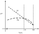
図3は、第1実施形態に係る火力発電プラントにおいて、蒸気加減弁122で生ずる圧力損失(絞り損失)のシミュレーション結果を示すグラフである。図3においては、縦軸が圧力損失(絞り損失)の値ΔP(対数値)を示し、横軸がタービン負荷TLを示している。
FIG. 3 is a graph showing simulation results of pressure loss (throttling loss) generated in the
圧力損失の値ΔPは、下記式(A)で求められる。式(A)において、ΔP1は、第1弁体31aの圧力損失の値であり、ΔP2は、第2弁体31bの圧力損失の値である。G1は、第1弁体31aが開いて通過する蒸気の流量であり、G2は、第2弁体31bが開いて通過する蒸気の流量である。式(A)から判るように、圧力損失(絞り損失)の値ΔPは、第1弁体31aの圧力損失の値ΔP1と、第2弁体31bの圧力損失の値ΔP2との加重平均値である。
The pressure loss value ΔP is determined by the following equation (A). In Formula (A), (DELTA) P1 is a value of the pressure loss of the
ΔP=(G1×ΔP1+G2×ΔP2)/(G1+G2) ・・・(A) ΔP = (G1 × ΔP1 + G2 × ΔP2) / (G1 + G2) (A)
図3のうち、太い一点鎖線FAは、絞り調速方式(全周噴射方式,Full Arc)の結果であって、タービン負荷TLに応じて第1弁体31aの開度と第2弁体31bの開度との両者が互いに同じ開度で大きくなる場合について示している。これに対して、太い破線PAは、ノズル締切調速方式(部分噴射方式,Partial Arc)の結果であって、タービン負荷TLに応じて第1弁体31aが全開状態になった後に第2弁体31bの開度が開く場合について示している。
In FIG. 3, the thick dashed-dotted line FA is the result of the throttle control system (full arc injection system, full arc), and the opening degree of the
図3に示すように、蒸気加減弁122で生ずる圧力損失の値ΔPは、タービン負荷TLがL13よりも小さい範囲では、ノズル締切調速方式(太い破線PA)の方が絞り調速方式(太い一点鎖線FA)の場合よりも小さい。この理由について説明する。ノズル締切調速方式(PA)の場合に第2弁体31bにおいて生ずる圧力損失の値ΔP2は、絞り調速方式(FA)の場合に第1弁体31aと第2弁体32bとにおいて生ずる圧力損失の値よりも大きい。しかし、タービン負荷TLがL13よりも小さい範囲では、ノズル締切調速方式(PA)の場合には第2弁体31bの開度が小さく、第2弁体31bが開くことで通過する蒸気の流量G2が小さい。このため、第2弁体31bで生ずる圧力損失の値ΔP2の影響が、上記式(A)において小さい。その結果、本範囲では、ノズル締切調速方式(PA)の方が絞り調速方式(FA)の場合よりも圧力損失の値ΔPが小さくなる。
As shown in FIG. 3, the pressure loss value .DELTA.P generated by the
これに対して、タービン負荷TLがL13よりも大きい範囲では、蒸気加減弁122で生ずる圧力損失の値ΔPは、絞り調速方式(太い一点鎖線FA)の場合の方がノズル締切調速方式(太い破線PA)の場合よりも小さい。この理由について説明する。絞り調速方式(PA)の場合、タービン負荷TLが定格負荷に近づくに伴って、蒸気量G1,G2は、漸近線的に等しくなる。そして、絞り調速方式(PA)の場合、第2弁体31bにおける圧力損失の値ΔP2の影響が上記式(A)において大きくなる。その結果、本範囲では、絞り調速方式(FA)の方がノズル締切調速方式(PA)の場合よりも圧力損失の値ΔPが小さくなる。
On the other hand, in the range where the turbine load TL is larger than L13, the pressure loss value .DELTA.P generated by the
タービン負荷TLがL13である場合、蒸気加減弁122で生ずる圧力損失の値ΔPは、絞り調速方式(太い一点鎖線FA)の場合とノズル締切調速方式(太い破線PA)の場合との間において同じである。
When the turbine load TL is L13, the pressure loss value ΔP generated by the
本実施形態においては、圧力損失の値ΔPが、L13のときに逆転することを利用して、タービン負荷TLがL13よりも小さい範囲では、ノズル締切調速方式(太い破線PA)を採用し、タービン負荷TLがL13よりも大きくなる範囲では、絞り調速方式(太い一点鎖線FA)を採用している。このため、本実施形態は、蒸気加減弁122の圧力損失を低減可能である。
In the present embodiment, the nozzle cut-off speed control system (thick broken line PA) is adopted in the range where the turbine load TL is smaller than L13 by utilizing the fact that the pressure loss value ΔP reverses at L13, In the range where the turbine load TL becomes larger than L13, the throttle speed control system (thick one-dot chain line FA) is adopted. For this reason, the present embodiment can reduce the pressure loss of the
図4は、第1実施形態に係る火力発電プラントにおいて、周方向エネルギー損失のシミュレーション結果を示すグラフである。図4においては、縦軸が周方向エネルギー損失の値EL(対数値)を示し、横軸がタービン負荷TLを示している。 FIG. 4 is a graph showing simulation results of circumferential energy loss in the thermal power plant according to the first embodiment. In FIG. 4, the vertical axis represents the circumferential energy loss value EL (logarithmic value), and the horizontal axis represents the turbine load TL.
図4に示すように、周方向エネルギー損失の値ELは、絞り調速方式(太い一点鎖線FA)の場合の方がノズル締切調速方式(太い破線PA)の場合よりも小さい。本実施形態では、タービン負荷TLがL13以上では、絞り調速方式を用いるので、ノズル締切調速方式に比べて、周方向エネルギー損失を低減可能である。 As shown in FIG. 4, the value EL of the circumferential energy loss is smaller in the case of the throttle speed control system (thick dashed-dotted line FA) than in the case of the nozzle cut-off speed control system (thick dashed line PA). In the present embodiment, when the turbine load TL is L13 or more, since the throttle control system is used, the circumferential energy loss can be reduced as compared with the nozzle shut-off control system.
図5は、第1実施形態に係る火力発電プラントにおいて、タービン内部効率のシミュレーション結果を示すグラフである。図5においては、縦軸がタービン内部効率TE(対数値)を示し、横軸がタービン負荷TLを示している。 FIG. 5 is a graph showing simulation results of turbine internal efficiency in the thermal power plant according to the first embodiment. In FIG. 5, the vertical axis represents the turbine internal efficiency TE (logarithmic value), and the horizontal axis represents the turbine load TL.
図5に示すように、タービン内部効率TEは、タービン負荷TLがL13よりも小さい範囲では、ノズル締切調速方式(太い破線PA)の方が絞り調速方式(太い一点鎖線FA)の場合よりも高い。タービン負荷TLがL13よりも大きい範囲では、タービン内部効率TEは、絞り調速方式(太い一点鎖線FA)の場合の方がノズル締切調速方式(太い破線PA)の場合よりも高い。タービン負荷TLがL13である場合、タービン内部効率TEは、絞り調速方式(太い一点鎖線FA)の場合とノズル締切調速方式(太い破線PA)の場合との間において同じである。 As shown in FIG. 5, in the turbine internal efficiency TE, in the range where the turbine load TL is smaller than L13, the nozzle shutoff speed control system (thick broken line PA) is better than the throttle speed control system (thick dashed line FA) Also high. In the range where the turbine load TL is larger than L13, the turbine internal efficiency TE is higher in the case of the throttle speed control system (thick dashed-dotted line FA) than in the case of the nozzle shutoff speed control system (thick dashed line PA). When the turbine load TL is L13, the turbine internal efficiency TE is the same between the case of the throttle regulation system (thick dashed-dotted line FA) and the case of the nozzle cut-off regulation system (thick dashed line PA).
本実施形態においては、タービン内部効率TEは、蒸気加減弁122で生ずる圧力損失の値ΔPの場合と同様に、タービン負荷TLがL13よりも小さい範囲では、ノズル締切調速方式(太い破線PA)が絞り調速方式(太い一点鎖線FA)より大きくなる。そして、タービン負荷TLがL13よりも大きくなる範囲では、タービン内部効率TEは、蒸気加減弁122で生ずる圧力損失の値ΔPの場合と同様に、絞り調速方式(太い一点鎖線FA)がノズル締切調速方式(太い破線PA)より大きくなる。このため、本実施形態は、タービン内部効率TEを向上可能である。
In the present embodiment, as in the case of the pressure loss value ΔP generated by the
なお、ボイラの制御方式(定圧、変圧)を切り替えるときの負荷は、上記に限定されず、蒸気室20の仕切り方により、変えられる。
In addition, the load at the time of switching the control system (constant pressure, transformation) of a boiler is not limited above, It is changed by the partition method of the
<第2実施形態>
図6,図7,図8,図9A〜図9D,図10は、第2実施形態に係る火力発電プラントを説明するための図である。
Second Embodiment
6, 7, 8, 9A to 9D and 10 are views for explaining a thermal power plant according to a second embodiment.
図6は、第2実施形態に係る火力発電プラントにおいて、高圧タービン111と蒸気加減弁122とが設けられた部分の概要を模式的に示す図である(図12参照)。
FIG. 6 is a view schematically showing an outline of a portion where the high pressure turbine 111 and the
図7は、第2実施形態に係る火力発電プラントにおいて、蒸気室20(図16参照)を示している。 FIG. 7 shows a steam room 20 (see FIG. 16) in the thermal power plant according to the second embodiment.
図8は、第2実施形態に係る火力発電プラントにおいて、ボイラ100の圧力制御方式を説明するための図である。
FIG. 8 is a diagram for explaining a pressure control method of the
図9Aは、第2実施形態に係る火力発電プラントにおいて、制御装置400の概要を示すブロック図である。制御装置400は、演算信号分配器404と第1関数器405aと第2関数器405bとの他に、第3関数器405cを更に有する。図9B、図9C,図9Dのそれぞれは、第1関数器405a、第2関数器405b、第3関数器405cのそれぞれを拡大して示している。
FIG. 9A is a block diagram showing an outline of a
図9Bでは、本実施形態において、第1関数器405aが有する第1の関数K405aについて太い実線で示している。図9Cでは、本実施形態において、第2関数器405bが有する第2の関数K405bについて太い実線で示している。図9Dでは、本実施形態において、第3関数器405cが有する第3の関数K405cについて太い実線で示している。
In FIG. 9B, in the present embodiment, the
また、図9B,図9C,図9Dには、タービン負荷信号S404の信号値が0からL32bである範囲で、第1弁体31aの開度と第2弁体31bの開度との両者を絞り調速方式で調整するときに用いる関数KF1の一部を太い一点鎖線で併記している。また、図9B,図9C,図9Dには、タービン負荷信号S404の信号値が0から100である範囲で、第1弁体31aの開度と第2弁体31bの開度と第3弁体31cの開度とを絞り調速方式で調整するときに用いる関数KF2の一部を太い一点鎖線で併記している。
9B, 9C, and 9D, both the opening degree of the
この他に、図9Bには、第1弁体31aの開度と第2弁体31bの開度と第3弁体31cの開度をノズル締切調速方式で調整する場合において、第1弁体31aの開度について調整するときに用いる関数KPaの一部を太い破線で併記している。図9Cには、上記のノズル締切調速方式で調整する場合において、第2弁体31bの開度について調整するときに用いる関数KPbの一部を太い破線で併記している。図9Dには、上記のノズル締切調速方式で調整する場合において、第3弁体31cの開度について調整するときに用いる関数KPcの一部を太い破線で併記している。
In addition, in FIG. 9B, when the opening degree of the
図10は、第2実施形態に係る火力発電プラントにおいて、蒸気加減弁122を構成する複数の弁体の開度を示すグラフである。
FIG. 10 is a graph showing the opening degree of a plurality of valve bodies constituting the
本実施形態は、図6に示すように、蒸気加減弁122の構成が、第1実施形態の場合(図16参照)と異なっている。本実施形態は、図7に示すように、蒸気室20の構成が、第1実施形態の場合(図20参照)と異なっている。本実施形態は、図8に示すように、ボイラ100の圧力制御方式が、第1実施形態の場合(図21参照)と異なっている。そして、図9Aから図9Dに示すように、本実施形態においては、制御装置400のうち、第1関数器405aが有する第1の関数K405a、および、第2関数器405bが有する第2の関数K405bが、第1実施形態の場合(図1参照)と異なっている。また、制御装置400は、第3関数器405cを更に有している。このため、図10に示すように、本実施形態では、タービン負荷TLと、蒸気加減弁122を構成する複数の弁体の開度Kとの関係が、第1実施形態の場合(図2参照)と異なっている。これらの点、および、関連する点を除き、本実施形態は、上述した第1実施形態の場合と同様である。このため、本実施形態において、上記記載と重複する個所については、適宜、説明を省略する。
In the present embodiment, as shown in FIG. 6, the configuration of the
まず、本実施形態の蒸気加減弁122について、図6を用いて説明する。
First, the
本実施形態において、蒸気加減弁122は、図6に示すように、複数の弁体31を有する。ここでは、蒸気加減弁122は、第1実施形態の場合(図16参照)と異なり、第1弁体31aと第2弁体31bとの他に、第3弁体31cが複数の弁体31として設けられている。第3弁体31cの開度は、第1弁体31aの開度および第2弁体31bの開度と第3弁体31cの開度と同様に、制御装置400によって制御される。
In the present embodiment, the
つぎに、本実施形態の蒸気室20について、図6と図7とを用いて説明する。
Next, the
本実施形態において、蒸気室20は、図6と図7とに示すように、第1実施形態の場合と異なり、仕切り20pによって、第1蒸気室部201と第2蒸気室部202と第3蒸気室部203とに区画されている。
In the present embodiment, as shown in FIGS. 6 and 7, the
第1蒸気室部201は、第1弁体31aが開けられることで主蒸気が流れる。第2蒸気室部202は、第2弁体31bが開けられることで主蒸気が流れる。第3蒸気室部203は、第3弁体31cが開けられることで主蒸気が流れる。
In the first
ここでは、第1蒸気室部201から第1段タービン段落21aへ主蒸気が流れる流路の第1段ノズル面積と、第2蒸気室部202から第1段タービン段落21aへ主蒸気が流れる流路の第1段ノズル面積とが、たとえば、同じになるように構成されている。また、第3蒸気室部203から第1段タービン段落21aへ主蒸気が流れる流路の第1段ノズル面積は、第1蒸気室部201の第1段ノズル面積および第2蒸気室部202の第1段ノズル面積よりも、たとえば、大きくなるように構成されている。たとえば、第1蒸気室部201の第1段ノズル面積と、第2蒸気室部202の第1段ノズル面積と、第3蒸気室部203の第1段ノズル面積との比は、3:3:4の関係である。
Here, the first stage nozzle area of the flow path in which the main steam flows from the first
つぎに、本実施形態におけるボイラ100の圧力制御方式について、図8を用いて説明する。
Next, a pressure control method of the
図8に示すように、ボイラ100は、第1実施形態の場合(図21参照)と同様に、タービン負荷TLに応じて、定圧方式CD1,CD2と変圧方式VDとを切り替えるように制御される。
As shown in FIG. 8, the
具体的には、タービン負荷TLが0からL31(たとえば、L31=20%)までの範囲においては、定圧方式CD1で運転を行う。タービン負荷TLがL31からL32(L32>L31,たとえば、L32=50%)までの範囲においては、変圧方式VDで運転を行う。タービン負荷TLがL32から100までの範囲においては、定圧方式CD2で運転を行う。 Specifically, in the range from 0 to L31 (for example, L31 = 20%) of the turbine load TL, the operation is performed by the constant pressure method CD1. When the turbine load TL is in the range from L31 to L32 (L32> L31, for example, L32 = 50%), operation is performed by the voltage transformation method VD. When the turbine load TL is in the range from L32 to L100, the operation is performed by the constant pressure system CD2.
つぎに、本実施形態の制御装置400について、図9Aを用いて説明する。
Next, the
図9Aに示すように、本実施形態においては、制御装置400は、第1関数器405aと第2関数器405bとの他に、第3関数器405cを更に有している。演算信号分配器404は、タービン負荷信号S404(流量要求信号)を第1関数器405aおよび第2関数器405bと共に、第3関数器405cに出力する。
As shown in FIG. 9A, in the present embodiment, the
第3関数器405cは、第3の関数K405cを記憶しており、第3の関数K405cを用いて、タービン負荷信号S404に応じた第3の弁開度演算信号S405cを演算する。第3の関数K405cは、タービン負荷信号S404を入力信号とし、第3の弁開度演算信号S405cを出力信号とした関数である。第3の弁開度演算信号S405cは、第3弁体31cを駆動する駆動装置(図示省略)に出力され、第3弁体31cの開度が第3の弁開度演算信号S405cに応じた開度に調整される。
The
本実施形態において、第1関数器405aが記憶する第1の関数K405aと、第2関数器405bが記憶する第2の関数K405bと、第3関数器405cが記憶する第3の関数K405cとについて、図9B,図9C,図9Dを用いて、詳細に説明する。
In the present embodiment, the
第1の関数K405aは、図9Bに示すように、タービン負荷信号S404の信号値が0からL31に増加するに伴って、第1の弁開度演算信号S405aの信号値が0から100に増加するように設定されている。そして、第1の関数K405aは、タービン負荷信号S404の信号値がL31からL33(たとえば、L33=70%)である範囲では、第1の弁開度演算信号S405aの信号値が100を保持するように設定されている。 In the first function K405a, as shown in FIG. 9B, as the signal value of the turbine load signal S404 increases from 0 to L31, the signal value of the first valve opening degree operation signal S405a increases from 0 to 100. It is set to Then, the first function K405a holds 100 as the signal value of the first valve opening degree operation signal S405a in the range where the signal value of the turbine load signal S404 is L31 to L33 (for example, L33 = 70%). Is set as.
第2の関数K405bは、図9Cに示すように、タービン負荷信号S404の信号値が0からL32(L33>L32>L31)である範囲では、第2の弁開度演算信号S405bの信号値が0を保持するように設定されている。そして、第2の関数K405bは、タービン負荷信号S404の信号値がL32からL33に増加するに伴って、第2の弁開度演算信号S405bの信号値が0からK31に増加するように設定されている。 As shown in FIG. 9C, in the second function K405b, when the signal value of the turbine load signal S404 is in the range of 0 to L32 (L33> L32> L31), the signal value of the second valve opening degree operation signal S405b is It is set to hold 0. The second function K405b is set so that the signal value of the second valve opening degree computing signal S405b increases from 0 to K31 as the signal value of the turbine load signal S404 increases from L32 to L33. ing.
タービン負荷信号S404の信号値がL33であるとき、第1の関数K405aは、図9Bに示すように、第1の弁開度演算信号S405aの信号値が100からK32に減少するように、設定されている。これに対して、第2の関数K405bは、図9Cに示すように、タービン負荷信号S404の信号値がL33であるとき、第2の弁開度演算信号S405bの信号値がK31からK32に増加するように、設定されている。つまり、タービン負荷信号S404の信号値がL33であるときには、第1の弁開度演算信号S405aの信号値と第2の弁開度演算信号S405bの信号値との両者は、K32であって、互いに同じになる。 When the signal value of the turbine load signal S404 is L33, the first function K405a is set so that the signal value of the first valve opening calculation signal S405a decreases from 100 to K32 as shown in FIG. 9B. It is done. On the other hand, as shown in FIG. 9C, when the signal value of the turbine load signal S404 is L33, the second function K405b increases the signal value of the second valve opening degree operation signal S405b from K31 to K32 It is set to do. That is, when the signal value of the turbine load signal S404 is L33, both the signal value of the first valve opening degree computing signal S405a and the signal value of the second valve opening degree computing signal S405b are K32, It will be the same as each other.
そして、タービン負荷信号S404の信号値がL33からL32bに増加するに伴って、第1の関数K405aは、図9Bに示すように、第1の弁開度演算信号S405aの信号値がK32から100に増加するように設定されている。同様に、第2の関数K405bは、図9Cに示すように、タービン負荷信号S404の信号値がL33からL32bに増加するに伴って、第2の弁開度演算信号S405bの信号値がK32から100に増加するように設定されている。つまり、タービン負荷信号S404の信号値がL33からL32bに増加するに伴って、第1の弁開度演算信号S405aの信号値と第2の弁開度演算信号S405bの信号値との両者は、K32から100に増加する。このように、タービン負荷信号S404の信号値がL33からL32bの範囲においては、第1の関数K405aと第2の関数K405bによって、それぞれ決まる開度は、互いに同じである。 Then, as the signal value of the turbine load signal S404 increases from L33 to L32b, as shown in FIG. 9B, the first function K405a has a signal value of the first valve opening degree operation signal S405a of K32 to 100. It is set to increase. Similarly, as shown in FIG. 9C, as the signal value of the turbine load signal S404 increases from L33 to L32b, the second function K405b causes the signal value of the second valve opening degree operation signal S405b to increase from K32 to It is set to increase to 100. That is, as the signal value of the turbine load signal S404 increases from L33 to L32b, both of the signal value of the first valve opening calculation signal S405a and the signal value of the second valve opening calculation signal S405b are Increase from K32 to 100. As described above, when the signal value of the turbine load signal S404 is in the range of L33 to L32b, the degree of opening determined by the first function K405a and the second function K405b is the same as each other.
本実施形態では、K32は、関数KF1(太い一点鎖線)において、タービン負荷信号S404の信号値がL33であるときに求められる値である。そして、第1の関数K405aと第2の関数K405bとの両者において、タービン負荷信号S404の信号値がL33からL32bに増加するに伴って、第1の弁開度演算信号S405aの信号値と第2の弁開度演算信号S405bの信号値とが増加する割合は、関数KF1の場合と同じである。 In the present embodiment, K32 is a value obtained when the signal value of the turbine load signal S404 is L33 in the function KF1 (thick alternate long and short dashed line). Then, in both of the first function K405a and the second function K405b, as the signal value of the turbine load signal S404 increases from L33 to L32b, the signal value of the first valve opening degree operation signal S405a and the first valve opening degree calculation signal S405a The rate at which the second valve opening degree calculation signal S405b and the signal value increase is the same as in the case of the function KF1.
第3の関数K405cは、図9Dに示すように、タービン負荷信号S404の信号値が0からL32bである範囲では、第3の弁開度演算信号S405cの信号値が0を保持するように設定されている。 As shown in FIG. 9D, the third function K405c is set so that the signal value of the third valve opening degree operation signal S405c holds 0 when the signal value of the turbine load signal S404 is in the range of 0 to L32b. It is done.
タービン負荷信号S404の信号値がL32bからL33bである範囲では、第1の関数K405aは、図9Bに示すように、第1の弁開度演算信号S405aの信号値が100を保持するように設定されている。同様に、第2の関数K405aは、図9Cに示すように、第2の弁開度演算信号S405bの信号値が100を保持するように設定されている。これに対して、第3の関数K405cは、図9Dに示すように、タービン負荷信号S404の信号値がL32bからL33bに増加するに伴って、第3の弁開度演算信号S405cの信号値が0からK31bに増加するように設定されている。
As shown in FIG. 9B, in the range where the signal value of the turbine load signal S404 is L32b to L33b, the first function K405a is set such that the signal value of the first valve opening degree operation signal S405a is maintained at 100. It is done. Similarly, as shown in FIG. 9C, the
タービン負荷信号S404の信号値がL33bであるとき、第1の関数K405aは、図9Bに示すように、第1の弁開度演算信号S405aの信号値が100からK32bに減少するように、設定されている。同様に、第2の関数K405bは、図9Cに示すように、タービン負荷信号S404の信号値がL33bであるとき、第2の弁開度演算信号S405bの信号値が100からK32bに減少するように、設定されている。これに対して、第3の関数K405cは、図9Dに示すように、タービン負荷信号S404の信号値がL33bであるとき、第3の弁開度演算信号S405cの信号値がK31bからK32bに増加するように、設定されている。つまり、タービン負荷信号S404の信号値がL33であるときには、第1の弁開度演算信号S405aの信号値と第2の弁開度演算信号S405bの信号値と第3の弁開度演算信号S405cの信号値とのそれぞれは、K32bであって、互いに同じになる。 When the signal value of the turbine load signal S404 is L33b, the first function K405a is set so that the signal value of the first valve opening calculation signal S405a decreases from 100 to K32b as shown in FIG. 9B. It is done. Similarly, as shown in FIG. 9C, when the signal value of the turbine load signal S404 is L33b, the second function K405b reduces the signal value of the second valve opening degree operation signal S405b from 100 to K32b. Is set. On the other hand, as shown in FIG. 9D, when the signal value of the turbine load signal S404 is L33b, the third function K405c increases the signal value of the third valve opening degree operation signal S405c from K31b to K32b. It is set to do. That is, when the signal value of the turbine load signal S404 is L33, the signal value of the first valve opening degree computing signal S405a, the signal value of the second valve opening degree computing signal S405b, and the third valve opening degree computing signal S405c. And K32b are the same as one another.
そして、タービン負荷信号S404の信号値がL33bから100に増加するに伴って、第1の関数K405aは、図9Bに示すように、第1の弁開度演算信号S405aの信号値がK32bから100に増加するように設定されている。同様に、第2の関数K405bは、図9Cに示すように、タービン負荷信号S404の信号値がL33bから100に増加するに伴って、第2の弁開度演算信号S405bの信号値がK32bから100に増加するように設定されている。また、同様に、第3の関数K405cは、図9Dに示すように、タービン負荷信号S404の信号値がL33bから100に増加するに伴って、第3の弁開度演算信号S405cの信号値がK32bから100に増加するように設定されている。つまり、タービン負荷信号S404の信号値がL33bから100に増加するに伴って、第1の弁開度演算信号S405aの信号値と第2の弁開度演算信号S405bの信号値と第3の弁開度演算信号S405cの信号値とのそれぞれは、K32bから100に増加する。このように、タービン負荷信号S404の信号値がL33bから100の範囲においては、第1の関数K405aと第2の関数K405bと第3の関数K405cによって決まる開度は、同じである。 Then, as the signal value of the turbine load signal S404 increases from L33b to 100, as shown in FIG. 9B, the first function K405a has a signal value of the first valve opening degree operation signal S405a of K32b to 100. It is set to increase. Similarly, as shown in FIG. 9C, as the signal value of the turbine load signal S404 increases from L33b to 100, the second function K405b causes the signal value of the second valve opening degree operation signal S405b to increase from K32b. It is set to increase to 100. Similarly, as shown in FIG. 9D, as the signal value of the turbine load signal S404 increases from L33b to 100, the third function K405c generates a signal value of the third valve opening degree operation signal S405c. It is set to increase from K32b to 100. That is, as the signal value of the turbine load signal S404 increases from L33b to 100, the signal value of the first valve opening degree computing signal S405a and the signal value of the second valve opening degree computing signal S405b, and the third valve Each of the opening degree operation signal S405c and the signal value increase from K32b to 100. As described above, when the signal value of the turbine load signal S404 is in the range of L33b to 100, the degree of opening determined by the first function K405a, the second function K405b, and the third function K405c is the same.
本実施形態では、K32bは、関数KF2(太い一点鎖線)において、タービン負荷信号S404の信号値がL33bであるときに求められる値である。そして、第1の関数K405aと第2の関数K405bと第3の関数K405cとのそれぞれにおいて、タービン負荷信号S404の信号値がL33bから100に増加するに伴って、第1の弁開度演算信号S405aの信号値と第2の弁開度演算信号S405bの信号値と第3の弁開度演算信号S405cの信号値とが増加する割合は、関数KF2の場合と同じである。 In the present embodiment, K32b is a value obtained when the signal value of the turbine load signal S404 is L33b in the function KF2 (thick alternate long and short dashed line). Then, in each of the first function K405a, the second function K405b, and the third function K405c, as the signal value of the turbine load signal S404 increases from L33b to 100, the first valve opening degree operation signal The rate at which the signal value of S405a, the signal value of the second valve opening calculation signal S405b, and the signal value of the third valve opening calculation signal S405c increase is the same as in the case of the function KF2.
つぎに、本実施形態において、第1弁体31aの開度K、第2弁体31bの開度K、および、第3弁体31cの開度Kと、タービン負荷TLとの関係に関して、図10を用いて説明する。
Next, in the present embodiment, the relationship between the opening degree K of the
定圧方式CD1で運転を行う際には、図10に示すように、タービン負荷TLが0からL31に増加するに伴って、第1弁体31aの開度Kが大きくなり、第1弁体31aが全閉状態(K=0)から全開状態(K=100)になる。このとき、第2弁体31bと第3弁体31cは、全閉状態(K=0)を保持する。
When operating with the constant pressure system CD1, as shown in FIG. 10, as the turbine load TL increases from 0 to L31, the opening degree K of the
変圧方式VDで運転を行う際には、タービン負荷TLがL31からL32までの範囲において、第1弁体31aは、全開状態(K=100)を保持する。このとき、第2弁体31bと第3弁体31cは、全閉状態(K=0)を保持する。
When operating with the transformation type VD, the
定圧方式CD2で運転を行う際において、タービン負荷TLがL32からL33までの範囲では、第1弁体31aは、全開状態(K=100)を保持する。第2弁体31bは、上記と異なり、タービン負荷TLに応じて開度Kが大きくなり、開度Kが全閉状態(K=0)からK31になる。これに対して、第3弁体31cは、上記と同様に、全閉状態(K=0)を保持する。
When operating with the constant pressure system CD2, the
定圧方式CD2で運転を行う際において、タービン負荷TLがL33からL32bまでの範囲では、第1弁体31aは、全開状態(K=100)を保持しない。第1弁体31aは、タービン負荷TLがL33であるときに、開度Kが全開状態(K=100)からK32になる(K32<100,たとえば、K32=80)。同様に、第2弁体31bは、タービン負荷TLがL33であるときに、開度KがK31からK32になる(K32>K31)。そして、タービン負荷TLがL33からL32bに増加するに伴って、第1弁体31aの開度K、および、第2弁体31bの開度Kは、K32から全開状態(K=100)になる。これに対して、第3弁体31cは、上記と同様に、全閉状態(K=0)を保持する。
When operating with the constant pressure system CD2, the
K32は、タービン負荷TLが0からL33である範囲で、第1弁体31aの開度Kと第2弁体31bの開度Kとの両者を絞り調速方式で調整する場合(太い一点鎖線FA1)において、タービン負荷TLがL33になるときに調整する開度である。タービン負荷TLがL33からL32bに増加するに伴って第1弁体31aの開度Kと第2弁体31bの開度Kとの両者が増加する割合は、第1弁体31aの開度Kと第2弁体31bの開度Kとの両者を絞り調速方式で調整したときに両者が増加する割合(太い一点鎖線FA1の延長線)と同じである。
K32 is a case where both the opening degree K of the
定圧方式CD2で運転を行う際において、タービン負荷TLがL32bからL33bまでの範囲では、第1弁体31aと第2弁体31bとの両者は、全開状態(K=100)を保持する。第3弁体31cは、上記と異なり、タービン負荷TLに応じて開度Kが大きくなり、開度Kが全閉状態(K=0)からK31bになる。
When operating with the constant pressure system CD2, both the
定圧方式CD2で運転を行う際において、タービン負荷TLがL33bから100までの範囲では、第1弁体31aと第2弁体31bとの両者は、全開状態(K=100)を保持しない。第1弁体31aと第2弁体31bとの両者は、タービン負荷TLがL33bであるときに、開度Kが全開状態(K=100)からK32bになる(K32b<100)。同様に、第3弁体31cは、タービン負荷TLがL33bであるときに、開度KがK31bからK32bになる(K32b>K31b)。そして、タービン負荷TLがL33bから100に増加するに伴って、第1弁体31aの開度K、第2弁体31bの開度K、および、第3弁体31cの開度Kは、K32bから全開状態(K=100)になる。
When the constant pressure system CD2 is operated, when the turbine load TL is in the range from L33b to 100, both the
K32bは、タービン負荷TLが0から100である範囲で、第1弁体31aの開度Kと第2弁体31bの開度Kと第3弁体31cの開度Kとのそれぞれを絞り調速方式で調整する場合(太い一点鎖線FA2)において、タービン負荷TLがL33bになるときの開度である。タービン負荷TLがL33bから100に増加するに伴って第1弁体31aの開度Kと第2弁体31bの開度Kと第3弁体31cの開度Kとのそれぞれが増加する割合は、絞り調速方式で調整する場合(太い一点鎖線FA2の延長線)と同じである。
K32b adjusts the opening degree K of the
図11は、第2実施形態に係る火力発電プラントについて、タービン内部効率を示す図である。 FIG. 11 is a diagram showing the turbine internal efficiency of the thermal power plant according to the second embodiment.
図11において、縦軸は、タービン内部効率TEを示し、横軸は、タービン負荷TLを示している。図11において、太い実線EX3は、本実施形態の結果を示している。これに対して、太い破線CXは、蒸気加減弁122を構成する第1弁体31aと第2弁体31bと第3弁体31cとのそれぞれをタービン負荷TLに応じてノズル締切調速方式で開けた場合の結果を示している。
In FIG. 11, the vertical axis indicates the turbine internal efficiency TE, and the horizontal axis indicates the turbine load TL. In FIG. 11, a thick solid line EX3 indicates the result of the present embodiment. On the other hand, the thick broken line CX indicates that the
図11に示すように、タービン負荷TLがL33からL32bである範囲においては、本実施形態の場合(太い実線EX3)の方が、蒸気加減弁122をノズル締切調速方式で開けた場合(太い破線CX)よりも、タービン内部効率TEが高い。同様に、タービン負荷TLがL33bから100である範囲においては、本実施形態の場合(太い実線EX3)の方が、蒸気加減弁122をノズル締切調速方式で開けた場合(太い破線CX)よりも、タービン内部効率TEが高い。
As shown in FIG. 11, in the case where the turbine load TL is L33 to L32 b, in the case of the present embodiment (thick solid line EX3), the
タービン負荷TLがL33からL32bである範囲、および、L33bから100である範囲では、本実施形態のタービン内部効率TE(太い実線EX3)は、絞り調速方式の場合(太い破線CX)と同じであって、ノズル締切調速方式の場合よりも高い。タービン負荷TLがL33からL32bである範囲と、L33bから100である範囲とを除く範囲では、本実施形態のタービン内部効率TEは、ノズル締切調速方式で開けた場合と同じである。このため、本実施形態は、タービン内部効率TEを向上可能である。 In the range where the turbine load TL is L33 to L32b and the range L33b to 100, the turbine internal efficiency TE (thick solid line EX3) of this embodiment is the same as in the case of the throttle control system (thick broken line CX) And higher than in the case of the nozzle cut-off speed control method. The turbine internal efficiency TE of the present embodiment is the same as in the case of opening by the nozzle cut-off speed control method in the range excluding the range where the turbine load TL is L33 to L32b and the range L33b to 100. For this reason, this embodiment can improve turbine internal efficiency TE.
したがって、本実施形態は、タービン内部効率(タービン調速段効率)を向上し、エネルギーを効率的に利用可能である。 Therefore, this embodiment improves the turbine internal efficiency (turbine speed control stage efficiency), and energy can be efficiently used.
なお、第1弁体31a、第2弁体31b、および、第3弁体31cとして機能する弁体、および、第1蒸気室部201、第2蒸気室部202、および、第3蒸気室部203として機能する蒸気室部が、複数であってもよい。
In addition, the valve body which functions as the
本発明のいくつかの実施形態を説明したが、これらの実施形態は、例として提示したものであり、発明の範囲を限定することは意図していない。これら新規な実施形態は、その他の様々な形態で実施されることが可能であり、発明の要旨を逸脱しない範囲で、種々の省略、置き換え、変更を行うことができる。これら実施形態やその変形は、発明の範囲や要旨に含まれるとともに、特許請求の範囲に記載された発明とその均等の範囲に含まれる。 While certain embodiments of the present invention have been described, these embodiments have been presented by way of example only, and are not intended to limit the scope of the invention. These novel embodiments can be implemented in various other forms, and various omissions, substitutions, and modifications can be made without departing from the scope of the invention. These embodiments and modifications thereof are included in the scope and the gist of the invention, and are included in the invention described in the claims and the equivalent scope thereof.
1…火力発電プラント、20…蒸気室、21…タービン段落、31…弁体、31a…第1弁体、31b…第2弁体、31c…第3弁体、100…ボイラ、101…蒸気発生器、102…再熱器、110…蒸気タービン部、111…高圧タービン、112…中圧タービン、113…低圧タービン、120…主蒸気系、121…蒸気止め弁、122…蒸気加減弁、130…再熱蒸気系、131…再熱蒸気止め弁、132…インターセプト弁、140…復水給水系、141…復水器、142…給水ポンプ、150…低温再熱系、151…逆止弁、160…高圧タービンバイパス系、161…高圧タービンバイパス弁、170…低圧タービンバイパス系、171…低圧タービンバイパス弁、201…第1蒸気室部、202…第2蒸気室部、203…第3蒸気室部、211…ノズル部、212…動翼部、400…制御装置、401…速度制御回路、402…負荷制御回路、403…加減算器、404…演算信号分配器、405a…第1関数器、405b…第2関数器、405c…第3関数器、K405a…第1の関数、K405b…第2の関数、K405c…第3の関数、KF…関数、KF1…関数、KF2…関数、KPa…関数、KPb…関数、KPc…関数、S401…タービン回転数制御信号、S402…タービン負荷設定信号、S403…加減算演算信号、S404…タービン負荷信号、S405a…第1の弁開度演算信号、S405b…第2の弁開度演算信号、S405c…第3の弁開度演算信号
DESCRIPTION OF
Claims (6)
前記蒸気加減弁は、第1弁体と第2弁体とを含み、
前記蒸気室は、第1蒸気室部と第2蒸気室部とを含み、前記第1弁体が開けられることで前記第1蒸気室部に主蒸気が流入し、前記第2弁体が開けられることで前記第2蒸気室部に主蒸気が流入するように構成されており、
前記制御装置は、
前記タービン負荷が第1負荷から前記第1負荷よりも大きい第2負荷までの範囲では、前記第1弁体の開度が全開状態を保持すると共に、前記第2弁体の開度が前記タービン負荷の増加に応じて全閉状態から第1開度になるように、前記蒸気加減弁の動作を制御し、
前記タービン負荷が前記第2負荷であるときには、前記第1弁体の開度が全開状態から第2開度になると共に、前記第2弁体の開度が前記第1開度から前記第2開度になり、前記タービン負荷が前記第2負荷から増加するに伴って、前記第1弁体、および、前記第2弁体が、同じ開度で、前記第2開度から全開状態になるように、前記蒸気加減弁の動作を制御する、
火力発電プラント。 A boiler, a steam turbine unit in which a main steam generated in the boiler flows into the steam chamber as a working fluid, a steam control valve for controlling the flow rate of the main steam flowing from the boiler to the steam chamber, and an operation of the steam control valve A thermal power plant having a controller for controlling the turbine according to the turbine load,
The steam control valve includes a first valve body and a second valve body,
The steam chamber includes a first steam chamber portion and a second steam chamber portion, and when the first valve body is opened, main steam flows into the first steam chamber portion, and the second valve body is opened. The main steam flows into the second steam chamber by being
The controller is
In the range from the first load to the second load where the turbine load is larger than the first load, the opening degree of the first valve body maintains the fully open state, and the opening degree of the second valve body is the turbine The operation of the steam control valve is controlled so as to change from the fully closed state to the first opening degree according to an increase in load,
When the turbine load is the second load, the opening degree of the first valve body changes from the fully open state to the second opening degree, and the opening degree of the second valve body is the second opening degree from the first opening degree When the turbine load increases from the second load, the first valve body and the second valve body are fully opened from the second opening at the same opening degree. To control the operation of the steam control valve,
Thermal power plant.
前記タービン負荷が前記第2負荷から前記第2負荷よりも大きい定格負荷までの範囲では、前記タービン負荷が増加するに伴って、前記第1弁体の開度、および、前記第2弁体の開度が前記第2開度から全開状態になるように、前記蒸気加減弁の動作を制御する、
請求項1に記載の火力発電プラント。 The controller is
In the range from the second load to the rated load where the turbine load is larger than the second load, the opening degree of the first valve body and the second valve body as the turbine load increases. The operation of the steam control valve is controlled so that the opening degree is fully opened from the second opening degree.
The thermal power plant according to claim 1.
請求項2に記載の火力発電プラント。 The second opening degree is adjusted when the turbine load becomes the second load in the case of adjusting the opening degree of the first valve body and the opening degree of the second valve body in a throttle control system. Opening degree,
The thermal power plant according to claim 2.
請求項3に記載の火力発電プラント。 The rate at which the opening degree of the first valve body and the opening degree of the second valve body increase as the turbine load increases from the second load to the rated load is determined by the opening of the first valve body. And the opening degree of the second valve body are adjusted by the throttle control method,
The thermal power plant according to claim 3.
前記蒸気室は、第3蒸気室部を更に含み、前記第3弁体が開けられることで前記第3蒸気室部に主蒸気が流入するように構成されており、
前記制御装置は、
前記タービン負荷が前記第2負荷から前記第2負荷よりも大きい第3負荷に増加するに伴って、前記第1弁体、および、前記第2弁体が、互いに同じ開度で、前記第2開度から全開状態になるように、前記蒸気加減弁の動作を制御し、
前記タービン負荷が前記第3負荷から前記第3負荷よりも大きい第4負荷までの範囲では、前記第1弁体の開度および前記第2弁体の開度が全開状態を保持すると共に、前記第3弁体の開度が前記タービン負荷の増加に応じて全閉状態から第3開度になるように、前記蒸気加減弁の動作を制御し、
前記タービン負荷が前記第4負荷であるときには、前記第1弁体の開度および前記第2弁体の開度が全開状態から第4開度になると共に、前記第3弁体の開度が前記第3開度から前記第4開度になり、前記タービン負荷が前記第4負荷から増加するに伴って、前記第1弁体、前記第2弁体、および、前記第3弁体のそれぞれが、同じ開度で、前記第4開度から全開状態になるように、前記蒸気加減弁の動作を制御する、
請求項1に記載の火力発電プラント。 The steam control valve further includes a third valve body,
The steam chamber further includes a third steam chamber, and the main valve flows into the third steam chamber by opening the third valve body.
The controller is
As the turbine load increases from the second load to a third load that is larger than the second load, the first valve body and the second valve body have the same opening degree as the second valve body. The operation of the steam control valve is controlled so as to be fully open from the opening degree,
In the range from the third load to the fourth load where the turbine load is larger than the third load, the opening degree of the first valve body and the opening degree of the second valve body maintain the fully open state, and The operation of the steam control valve is controlled such that the third valve body has a third valve opening from a fully closed state in response to an increase in the turbine load.
When the turbine load is the fourth load, the opening degree of the first valve body and the opening degree of the second valve body change from the fully open state to the fourth opening degree, and the opening degree of the third valve body is Each of the first valve body, the second valve body, and the third valve body as the third opening degree changes to the fourth opening degree and the turbine load increases from the fourth load. Control the operation of the steam control valve so that the fourth opening degree becomes fully open at the same opening degree,
The thermal power plant according to claim 1.
前記タービン負荷が第1負荷から前記第1負荷よりも大きい第2負荷までの範囲では、前記第1弁体の開度が全開状態を保持すると共に、前記第2弁体の開度が前記タービン負荷の増加に応じて全閉状態から第1開度になるように、前記蒸気加減弁の動作を制御し、
前記タービン負荷が前記第2負荷であるときには、前記第1弁体の開度が全開状態から第2開度になると共に、前記第2弁体の開度が前記第1開度から前記第2開度になり、前記タービン負荷が前記第2負荷から増加するに伴って、前記第1弁体、および、前記第2弁体が、同じ開度で、前記第2開度から全開状態になるように、前記蒸気加減弁の動作を制御する、
火力発電プラントの運転方法。 A steam turbine unit in which a main steam generated in the boiler flows into the steam chamber as a working fluid; and a steam control valve controlling the flow rate of the main steam flowing from the boiler to the steam chamber; The valve includes at least a first valve body and a second valve body, the steam chamber includes at least a first steam chamber and a second steam chamber, and the first valve is opened to open the first steam. The main steam flows into the chamber and the second valve body is opened so that the main steam flows into the second steam chamber, and the operation of the steam control valve according to the turbine load is performed. The operating method of the thermal power plant to be controlled,
In the range from the first load to the second load where the turbine load is larger than the first load, the opening degree of the first valve body maintains the fully open state, and the opening degree of the second valve body is the turbine The operation of the steam control valve is controlled so as to change from the fully closed state to the first opening degree according to an increase in load,
When the turbine load is the second load, the opening degree of the first valve body changes from the fully open state to the second opening degree, and the opening degree of the second valve body is the second opening degree from the first opening degree When the turbine load increases from the second load, the first valve body and the second valve body are fully opened from the second opening at the same opening degree. To control the operation of the steam control valve,
How to operate a thermal power plant.
Priority Applications (1)
| Application Number | Priority Date | Filing Date | Title |
|---|---|---|---|
| JP2015243550A JP6523940B2 (en) | 2015-12-14 | 2015-12-14 | Thermal power plant and method of operating the same |
Applications Claiming Priority (1)
| Application Number | Priority Date | Filing Date | Title |
|---|---|---|---|
| JP2015243550A JP6523940B2 (en) | 2015-12-14 | 2015-12-14 | Thermal power plant and method of operating the same |
Publications (2)
| Publication Number | Publication Date |
|---|---|
| JP2017110512A JP2017110512A (en) | 2017-06-22 |
| JP6523940B2 true JP6523940B2 (en) | 2019-06-05 |
Family
ID=59079472
Family Applications (1)
| Application Number | Title | Priority Date | Filing Date |
|---|---|---|---|
| JP2015243550A Active JP6523940B2 (en) | 2015-12-14 | 2015-12-14 | Thermal power plant and method of operating the same |
Country Status (1)
| Country | Link |
|---|---|
| JP (1) | JP6523940B2 (en) |
Family Cites Families (3)
| Publication number | Priority date | Publication date | Assignee | Title |
|---|---|---|---|---|
| JPS61106903A (en) * | 1984-10-31 | 1986-05-24 | Hitachi Ltd | Speed governing type change-over device |
| JPH0751882B2 (en) * | 1985-01-18 | 1995-06-05 | 株式会社日立製作所 | Turbine control device control method |
| JP4183653B2 (en) * | 2004-03-31 | 2008-11-19 | 株式会社東芝 | Thermal power plant and operation method |
-
2015
- 2015-12-14 JP JP2015243550A patent/JP6523940B2/en active Active
Also Published As
| Publication number | Publication date |
|---|---|
| JP2017110512A (en) | 2017-06-22 |
Similar Documents
| Publication | Publication Date | Title |
|---|---|---|
| US10830123B2 (en) | Systems and method for a waste heat-driven turbocharger system | |
| JP5734792B2 (en) | Steam turbine plant and operation method thereof | |
| US4403476A (en) | Method for operating a steam turbine with an overload valve | |
| US8863522B2 (en) | Operating steam turbine reheat section with overload valve | |
| US9882453B2 (en) | Method for providing a frequency response for a combined cycle power plant | |
| KR102489693B1 (en) | Systems and methods for dynamic balancing of steam turbine rotor thrust | |
| JP6523940B2 (en) | Thermal power plant and method of operating the same | |
| JP2010121598A (en) | Gas turbine operation control device and method | |
| JP5993137B2 (en) | Turbomachine starting method | |
| US11255224B2 (en) | Method for the short-term adjustment of the output of a combined-cycle power plant steam turbine, for primary frequency control | |
| KR102008055B1 (en) | Method for expanding a gas flow and device thereby applied | |
| JP5965143B2 (en) | How to shut down turbomachine | |
| JP6678561B2 (en) | Turbine control device and geothermal turbine power generation equipment | |
| JP6022712B2 (en) | Method for controlling a thermal power plant using a regulating valve | |
| JP2020125700A (en) | Power generation facility, power generation facility control device, and power generation facility control method | |
| JP2017057837A (en) | Steam turbine appliance and operational method of steam turbine appliance | |
| JP2012127339A (en) | Operation method of turbomachine in load operation process | |
| JP6892405B2 (en) | Geothermal combined power generation system | |
| JP2003254011A (en) | Operating method for multi-shaft type combined cycle power generating plant | |
| JP6625848B2 (en) | Steam control valve control device, power plant and steam control valve control method | |
| JP2019218867A (en) | Combined cycle power generation plant | |
| JP2024009646A (en) | Control device, control method and control progra mfor steam power generation plant | |
| JP2017015016A (en) | Power generation system and power generation method | |
| WO2020115463A1 (en) | A method and apparatus for controlling the flow of exhaust fluid to a turbogenerator | |
| JP2015094305A (en) | Steam turbine system |
Legal Events
| Date | Code | Title | Description |
|---|---|---|---|
| A711 | Notification of change in applicant |
Free format text: JAPANESE INTERMEDIATE CODE: A711 Effective date: 20171201 Free format text: JAPANESE INTERMEDIATE CODE: A712 Effective date: 20171201 |
|
| A621 | Written request for application examination |
Free format text: JAPANESE INTERMEDIATE CODE: A621 Effective date: 20180531 |
|
| A977 | Report on retrieval |
Free format text: JAPANESE INTERMEDIATE CODE: A971007 Effective date: 20190314 |
|
| TRDD | Decision of grant or rejection written | ||
| A01 | Written decision to grant a patent or to grant a registration (utility model) |
Free format text: JAPANESE INTERMEDIATE CODE: A01 Effective date: 20190402 |
|
| A61 | First payment of annual fees (during grant procedure) |
Free format text: JAPANESE INTERMEDIATE CODE: A61 Effective date: 20190426 |
|
| R150 | Certificate of patent or registration of utility model |
Ref document number: 6523940 Country of ref document: JP Free format text: JAPANESE INTERMEDIATE CODE: R150 |