JP6523925B2 - Authentication apparatus using biometric information and authentication method - Google Patents
Authentication apparatus using biometric information and authentication method Download PDFInfo
- Publication number
- JP6523925B2 JP6523925B2 JP2015220027A JP2015220027A JP6523925B2 JP 6523925 B2 JP6523925 B2 JP 6523925B2 JP 2015220027 A JP2015220027 A JP 2015220027A JP 2015220027 A JP2015220027 A JP 2015220027A JP 6523925 B2 JP6523925 B2 JP 6523925B2
- Authority
- JP
- Japan
- Prior art keywords
- finger
- image
- authentication
- distance
- light
- Prior art date
- Legal status (The legal status is an assumption and is not a legal conclusion. Google has not performed a legal analysis and makes no representation as to the accuracy of the status listed.)
- Active
Links
- 238000000034 method Methods 0.000 title claims description 114
- 238000012545 processing Methods 0.000 claims description 68
- 238000003384 imaging method Methods 0.000 claims description 51
- 210000003462 vein Anatomy 0.000 claims description 29
- 238000009826 distribution Methods 0.000 claims description 22
- 238000012937 correction Methods 0.000 claims description 17
- 238000000605 extraction Methods 0.000 claims description 17
- 230000001678 irradiating effect Effects 0.000 claims description 9
- 238000003860 storage Methods 0.000 claims description 8
- 239000000284 extract Substances 0.000 claims description 5
- 210000003811 finger Anatomy 0.000 description 481
- 230000036544 posture Effects 0.000 description 79
- 230000008569 process Effects 0.000 description 34
- 238000001514 detection method Methods 0.000 description 32
- 238000005259 measurement Methods 0.000 description 29
- 239000004973 liquid crystal related substance Substances 0.000 description 18
- 238000005096 rolling process Methods 0.000 description 16
- 230000033001 locomotion Effects 0.000 description 12
- 230000037303 wrinkles Effects 0.000 description 12
- 239000003925 fat Substances 0.000 description 10
- 230000035945 sensitivity Effects 0.000 description 10
- 230000000694 effects Effects 0.000 description 9
- 210000003491 skin Anatomy 0.000 description 9
- 239000013598 vector Substances 0.000 description 9
- XUMBMVFBXHLACL-UHFFFAOYSA-N Melanin Chemical compound O=C1C(=O)C(C2=CNC3=C(C(C(=O)C4=C32)=O)C)=C2C4=CNC2=C1C XUMBMVFBXHLACL-UHFFFAOYSA-N 0.000 description 8
- 210000004204 blood vessel Anatomy 0.000 description 8
- 238000006243 chemical reaction Methods 0.000 description 8
- 230000006870 function Effects 0.000 description 8
- 210000001145 finger joint Anatomy 0.000 description 7
- 238000010079 rubber tapping Methods 0.000 description 7
- 230000005540 biological transmission Effects 0.000 description 6
- 230000008859 change Effects 0.000 description 6
- 102000001554 Hemoglobins Human genes 0.000 description 5
- 108010054147 Hemoglobins Proteins 0.000 description 5
- 238000005452 bending Methods 0.000 description 5
- 238000005516 engineering process Methods 0.000 description 5
- 230000001965 increasing effect Effects 0.000 description 5
- 238000004364 calculation method Methods 0.000 description 4
- 238000010801 machine learning Methods 0.000 description 4
- 238000007637 random forest analysis Methods 0.000 description 4
- 230000003595 spectral effect Effects 0.000 description 4
- 210000001519 tissue Anatomy 0.000 description 4
- 244000060701 Kaempferia pandurata Species 0.000 description 3
- 235000016390 Uvaria chamae Nutrition 0.000 description 3
- 239000008280 blood Substances 0.000 description 3
- 210000004369 blood Anatomy 0.000 description 3
- 238000010586 diagram Methods 0.000 description 3
- 210000002615 epidermis Anatomy 0.000 description 3
- 230000005057 finger movement Effects 0.000 description 3
- 230000003287 optical effect Effects 0.000 description 3
- 229920006395 saturated elastomer Polymers 0.000 description 3
- 239000007787 solid Substances 0.000 description 3
- 238000012795 verification Methods 0.000 description 3
- 238000010521 absorption reaction Methods 0.000 description 2
- NIXOWILDQLNWCW-UHFFFAOYSA-N acrylic acid group Chemical group C(C=C)(=O)O NIXOWILDQLNWCW-UHFFFAOYSA-N 0.000 description 2
- 238000013459 approach Methods 0.000 description 2
- 230000002238 attenuated effect Effects 0.000 description 2
- 230000004397 blinking Effects 0.000 description 2
- 230000000903 blocking effect Effects 0.000 description 2
- 230000007423 decrease Effects 0.000 description 2
- 210000005224 forefinger Anatomy 0.000 description 2
- 230000006872 improvement Effects 0.000 description 2
- 230000006698 induction Effects 0.000 description 2
- 238000009434 installation Methods 0.000 description 2
- 239000000203 mixture Substances 0.000 description 2
- NJPPVKZQTLUDBO-UHFFFAOYSA-N novaluron Chemical compound C1=C(Cl)C(OC(F)(F)C(OC(F)(F)F)F)=CC=C1NC(=O)NC(=O)C1=C(F)C=CC=C1F NJPPVKZQTLUDBO-UHFFFAOYSA-N 0.000 description 2
- 238000000513 principal component analysis Methods 0.000 description 2
- 238000001228 spectrum Methods 0.000 description 2
- 230000000007 visual effect Effects 0.000 description 2
- INGWEZCOABYORO-UHFFFAOYSA-N 2-(furan-2-yl)-7-methyl-1h-1,8-naphthyridin-4-one Chemical compound N=1C2=NC(C)=CC=C2C(O)=CC=1C1=CC=CO1 INGWEZCOABYORO-UHFFFAOYSA-N 0.000 description 1
- 238000012935 Averaging Methods 0.000 description 1
- 206010052849 Oblique presentation Diseases 0.000 description 1
- 206010034972 Photosensitivity reaction Diseases 0.000 description 1
- 230000001133 acceleration Effects 0.000 description 1
- 230000009471 action Effects 0.000 description 1
- 238000004458 analytical method Methods 0.000 description 1
- 210000000617 arm Anatomy 0.000 description 1
- 210000001367 artery Anatomy 0.000 description 1
- 230000008901 benefit Effects 0.000 description 1
- 210000001736 capillary Anatomy 0.000 description 1
- 238000004891 communication Methods 0.000 description 1
- 238000012790 confirmation Methods 0.000 description 1
- 238000013527 convolutional neural network Methods 0.000 description 1
- 238000005520 cutting process Methods 0.000 description 1
- 239000000428 dust Substances 0.000 description 1
- 210000005069 ears Anatomy 0.000 description 1
- 238000000295 emission spectrum Methods 0.000 description 1
- 230000002708 enhancing effect Effects 0.000 description 1
- 238000011156 evaluation Methods 0.000 description 1
- 238000007667 floating Methods 0.000 description 1
- 210000002683 foot Anatomy 0.000 description 1
- 230000004927 fusion Effects 0.000 description 1
- 238000009499 grossing Methods 0.000 description 1
- 210000004247 hand Anatomy 0.000 description 1
- 238000012880 independent component analysis Methods 0.000 description 1
- 230000031700 light absorption Effects 0.000 description 1
- 230000007257 malfunction Effects 0.000 description 1
- 210000003739 neck Anatomy 0.000 description 1
- 206010033675 panniculitis Diseases 0.000 description 1
- 230000036211 photosensitivity Effects 0.000 description 1
- 238000007781 pre-processing Methods 0.000 description 1
- 230000035484 reaction time Effects 0.000 description 1
- 238000011084 recovery Methods 0.000 description 1
- 230000004044 response Effects 0.000 description 1
- 230000002441 reversible effect Effects 0.000 description 1
- 238000000926 separation method Methods 0.000 description 1
- 210000004003 subcutaneous fat Anatomy 0.000 description 1
- 210000004304 subcutaneous tissue Anatomy 0.000 description 1
- 230000008961 swelling Effects 0.000 description 1
- 230000001360 synchronised effect Effects 0.000 description 1
- 238000012546 transfer Methods 0.000 description 1
- -1 veins Chemical compound 0.000 description 1
- 210000000707 wrist Anatomy 0.000 description 1
Images


Classifications
-
- A—HUMAN NECESSITIES
- A61—MEDICAL OR VETERINARY SCIENCE; HYGIENE
- A61B—DIAGNOSIS; SURGERY; IDENTIFICATION
- A61B5/00—Measuring for diagnostic purposes; Identification of persons
- A61B5/117—Identification of persons
- A61B5/1171—Identification of persons based on the shapes or appearances of their bodies or parts thereof
-
- G—PHYSICS
- G06—COMPUTING; CALCULATING OR COUNTING
- G06T—IMAGE DATA PROCESSING OR GENERATION, IN GENERAL
- G06T1/00—General purpose image data processing
-
- G—PHYSICS
- G06—COMPUTING; CALCULATING OR COUNTING
- G06T—IMAGE DATA PROCESSING OR GENERATION, IN GENERAL
- G06T7/00—Image analysis
Description
本発明は、生体を用いて個人を認証する認証システムに関し、特に、小型で利便性に優れ、高精度な認証技術に関する。 The present invention relates to an authentication system that authenticates an individual using a living body, and more particularly to a small, convenient, and highly accurate authentication technique.
様々な生体認証技術の中でも、指静脈認証は高精度な認証を実現できるものとして知られている。指静脈認証は、指内部の血管パターンを使用するため優れた認証精度を実現し、かつ指紋認証に比べて偽造及び改ざんが困難であることによって、高度なセキュリティを実現できる。 Among various biometric authentication techniques, finger vein authentication is known as one that can realize highly accurate authentication. The finger vein authentication achieves excellent authentication accuracy because it uses a blood vessel pattern inside the finger, and high security can be realized by forgery and tampering compared to fingerprint authentication.
近年では、携帯電話機、ノート型PC(Personal Computer)、スマートフォンやタブレット端末などの携帯端末、ロッカー、金庫、プリンターなどの機器に生体認証装置を搭載し、各機器のセキュリティを確保する事例が増加している。また、生体認証が適用される分野として、入退室管理、勤怠管理、コンピュータへのログインなどに加え、近年では決済などにも生体認証が利用されてきている。特に公共で利用される生体認証装置は、確実な個人認証を実現することが重要である。さらには、近年のタブレット型携帯端末の普及やウェアラブル・コンピューティングの潮流を鑑みると、上記のように利便性を担保しつつ、装置の小型化を実現することも重要な要件の一つとなる。また、利用者が認証装置を容易に利用できるように、操作性の高い認証装置を提供することも重要となる。 In recent years, increasing cases of securing the security of each device by installing a biometric authentication device on devices such as mobile phones, laptop PCs (Personal Computers), smartphones and tablet terminals, lockers, safes, printers, etc. ing. Further, as fields to which biometrics authentication is applied, biometrics authentication has been used in recent years in addition to entry and exit management, attendance management, login to a computer, and the like. In particular, it is important for biometric authentication devices used in the public to realize reliable personal authentication. Furthermore, in view of the spread of tablet type portable terminals in recent years and the trend of wearable computing, it is also one of the important requirements to realize the miniaturization of the device while securing the convenience as described above. It is also important to provide an authentication device with high operability so that the user can easily use the authentication device.
血管の形状に基づいて個人認証を行う認証装置における小型化に関する技術として、特許文献1がある。
There is a
また特許文献2には、装置に非接触状態でかざされた掌を、赤色を含む可視光源の反射画像をカラーカメラで撮影し、掌の静脈と掌紋とを抽出して認証を行う技術が開示されている。
Further,
小型で使い勝手が良く、そして高精度な個人認証装置を実現するためには、面積の狭いセンサより広範囲の生体情報を撮影すること、そして生体を提示する際の位置ずれを効果的に補正すること、あるいは位置ずれが生じている場合に正しい位置を利用者に誘導することが重要となる。 In order to realize a small-sized, easy-to-use, high-accuracy personal identification device, it is necessary to capture a wide range of biological information from a narrow-area sensor and to effectively correct positional deviation when presenting a living body. It is important to guide the user to the correct position if there is a position shift.
特許文献1に記載の生体認証装置では、装置小型化のためにセンサの開口部を指の幅より狭くしているが、指を接触して提示することから指の輪郭が撮影できず、よって指の位置ずれが生じている場合の位置補正が困難となり、さらにはその解決手段に関する言及がなかった。また指を装置の所定の位置に置く必要があるため広範囲の生体情報を撮影することができず、さらには指置き台を具備する必要があるため装置の小型化が困難であった。
In the biometric authentication device described in
特許文献2には、スマホやタブレットに標準装備されているカラーカメラと、環境光あるいは液晶画面の光とを利用して、掌静脈と掌紋とを同時に撮影して認証する技術が記載されている。この技術は、装置に接触することなく掌の生体情報を広く撮影できる利点を有する。しかしながら、利用者が適切な位置に生体を停止させるなどのガイダンスについて開示されていない。
そこで本発明では、小型で使い勝手が良い高精度な個人認証を実現するべく、生体を提示する際の自由度を高く保ちつつ、個人を特徴付ける情報を多分に有する生体特徴の情報を取得することが可能な個人認証装置を実現することを目的とする。 Therefore, in the present invention, in order to realize a compact, easy-to-use and highly accurate personal authentication, it is possible to acquire information of a biometric feature having a large amount of information characterizing an individual while maintaining a high degree of freedom when presenting a biometric. It aims at realizing a possible personal identification device.
生体の特徴を用いて個人を認証する認証装置であって、生体が設置される設置領域と、前記設置領域に提示された生体に光を照射する光源と、前記生体を反射した前記光源からの光を撮影する撮像部と、前記撮像部によって撮像された画像を処理する画像処理部と、前記画像から前記生体の生体特徴を抽出する特徴抽出部と、前記生体特徴を保持する記憶部と、前記生体特徴の類似度を比較する照合部、を備え、前記撮像装置および前記複数光源は前記生体と向かい合う位置に配置され、前記複数光源は各々異なる波長を照射し、かつ前記撮像装置は複数の波長を撮影し、前記生体と前記撮像装置との距離を測定する手段を有し、前記生体の姿勢を判定して最適な提示位置を検出してその位置に誘導し、前記生体の姿勢に基づいて前記生体の特徴の補正を行うことを特徴とする認証装置である。 An authentication apparatus for authenticating an individual using characteristics of a living body, comprising: an installation area where the living body is installed, a light source for irradiating light to the living body presented in the installation area, and the light source reflecting the living body An imaging unit configured to capture light; an image processing unit configured to process an image captured by the imaging unit; a feature extraction unit configured to extract a biological feature of the living body from the image; a storage unit configured to hold the biological feature; A collating unit that compares the degree of similarity of the biological features, the imaging device and the plurality of light sources are disposed at a position facing the living body, the plurality of light sources respectively emit different wavelengths, and the imaging devices are a plurality of Based on the posture of the living body, it has means for photographing the wavelength and measuring the distance between the living body and the imaging device, determining the posture of the living body, detecting the optimum presentation position and guiding it to that position. Of the living body An authentication device and performs butterfly correction.
本発明によれば、指を用いた生体認証装置において、装置筺体が小型でありながらも広い範囲の生体を撮影でき、そこから多様な生体特徴を獲得することで高精度に認証を行うことができ、また指の位置ずれが生じた場合においても位置を補正あるいは検知することができ、小型で利便性に優れた認証精度の高い認証装置を提供することができる。 According to the present invention, in a biometric authentication device using a finger, it is possible to capture a wide range of living body even though the device housing is small, and perform authentication with high accuracy by acquiring various biological features therefrom. In addition, it is possible to correct or detect the position even when the positional deviation of the finger occurs, and it is possible to provide a small-sized, highly convenient authentication device with high authentication accuracy.
図1は、第1の実施の形態の指の血管を用いた生体認証システムの全体の構成を示す図である。尚、本発明はシステムとしてではなく、すべてまたは一部の構成を筐体に搭載した装置としての構成であってもよいことは言うまでも無い。装置は、認証処理を含めた個人認証装置としても良いし、認証処理は装置外部で行い、血管画像の取得に特化した血管画像取得装置、血管画像抽出装置としてもよい。また、後述のように端末としての実施形態であってもよい。 FIG. 1 is a diagram showing an entire configuration of a biometric system using blood vessels of a finger according to the first embodiment. Incidentally, it goes without saying that the present invention may be configured as an apparatus in which all or a part of the configuration is mounted in a housing, not as a system. The apparatus may be a personal authentication apparatus including an authentication process, or the authentication process may be performed outside the apparatus and may be a blood vessel image acquisition apparatus specialized for acquiring a blood vessel image or a blood vessel image extraction apparatus. Also, as described later, the embodiment may be a terminal.
実施1の形態の認証システムは、入力装置2、認証処理部10、記憶装置14、表示部15、入力部16、スピーカ17及び画像入力部18を含む。
The authentication system according to the first embodiment includes an
入力装置2は、その筐体に設置された光源3及び筐体内部に設置された撮像装置9を含む。なお、認証処理部10の画像処理機能の部分、又は、この画像処理機能に画像入力部18を含めて画像処理部という場合がある。いずれにしても、認証処理部10は認証に関わる処理を実行する処理部の総称であり、画像から生体(指)とシステムとの距離又は生体(指)の姿勢を判断する判断部や、生体(指)との距離又は生体(指)の姿勢の修正指示を表示部等に行う状態制御部や、撮像した画像から不要情報(しわ、背景、等)を除去する不要情報除去部や、撮像した画像から特徴情報を抽出する特徴抽出部や、抽出した特徴情報と記憶装置に予め格納した登録データとを照合する照合部等を備える。
The
光源3は、例えば、LED(Light Emitting Diode)などの発光素子であり、入力装置2の上部に提示された指1に光を照射する。撮像装置9は、入力装置2に提示された指1の画像を撮影する。なお、指1は複数本であっても良い。
画像入力部18は、入力装置2の撮像装置9で撮影された画像を取得し、取得した画像を認証処理部10へ入力する。
The
The
認証処理部10は、中央処理部(CPU:Central Processing Unit)11、メモリ12及び種々のインターフェイス(IF)13を含む。
The
CPU11は、メモリ12に記憶されているプログラムを実行することによって各種処理を行う。メモリ12は、CPUによって実行されるプログラムを記憶する。また、メモリ12は、画像入力部18から入力された画像を一時的に記憶する。
The
インターフェイス13は、認証処理部10と外部の装置とを接続する。具体的には、インターフェイス13は、入力装置2、記憶装置14、表示部15、入力部16、スピーカ17及び画像入力部18などと接続する。
The
記憶装置14は、利用者の登録データを予め記憶している。登録データは、利用者を照合するための情報であり、例えば、指静脈パターンの画像等である。通常、指静脈パターンの画像は、主に指の掌側の皮下に分布する血管(指静脈)を暗い影のパターンとして撮像した画像である。
The
表示部15は、例えば、液晶ディスプレイであり、認証処理部10から受信した情報を表示する出力装置である。
The
入力部16は、例えば、キーボードであり、利用者から入力された情報を認証処理部10に送信する。スピーカ17は、認証処理部10から受信した情報を、音響信号(例えば、音声)で発信する出力装置である。
The
ここで、表示部15及びスピーカ17は、この認証システムを利用するユーザに対して生体(指)とシステムとの距離や、生体(指)の姿勢の修正を指示するための装置(指示部)としての一例であり、本発明はこの装置に限定されるものではない。
Here, the
また、上記で説明した各処理部は、ひとつのCPUで全ての処理を行っても良いし、処理部毎にCPUを用いても良い。 In addition, each processing unit described above may perform all processing by one CPU, or may use a CPU for each processing unit.
図2は、第1の実施の形態の生体認証システムの入力装置の構造を説明する図である。 FIG. 2 is a diagram for explaining the structure of the input device of the biometric authentication system according to the first embodiment.
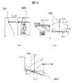
入力装置2は、指の表面あるいは皮下に分布する生体特徴を撮影する。入力装置2は装置筺体21で囲われ、その内部には2台の撮像装置9が配置されており、また複数の赤外光源31および可視光源32は撮像装置9の周囲に円環状に交互に配置され、開口部を介して指1を一様に照らすことができる。赤外光源31は赤外光を、可視光源32は可視光を照射する。可視光源32の波長は、概ね450nmから570nm程度、すなわち青から緑の波長から任意に選択できる。また光源31と光源32はそれぞれ任意の強度で照射できるものとする。具体的な波長の一例として、光源31は850nmの赤外光、光源32は550nmの緑色の波長を選択する。なお、各波長の発光素子は一体となっていてもよい。開口部にはアクリル板22がはめ込まれており、埃などが装置内部に侵入することを防いだり、装置内部の部材を物理的に保護したりする効果を有する。なお、光源31および光源32の照射する光がアクリル板22に反射すると被写体が見えなくなるため、すべての光源を時系列的に点灯して被写体を連続撮影し、各画像をHDR(High dynamic range)技術により合成し、反射成分のない鮮明な被写体を獲得しても良い。なお、光源31および光源32は、撮像装置9の周囲ではなく、2つの撮像装置9の間に円環状ないしは格子状に配置しても良く、2つの撮像装置9を取り囲むように円環状ないしは格子状に配置しても良い。
The
撮像装置9はカラーカメラであり、可視光と赤外光の波長帯に感度を持つ複数の受光素子を有する。撮像装置9は、たとえば青(B)、緑(G)、赤(R)に受光感度を持つ3種類のCMOSまたはCCD素子を有し、これらがBayer配列として知られる通り、格子状に配置されている。またRGBの各素子は近赤外光にも感度を有する。各受光素子の感度は、たとえば青で450nm付近、緑で550nm付近、 赤で620nm付近に受光感度のピークを持つセンサから構成される。また撮影されるカラー画像はRGBそれぞれの色プレーンが独立に獲得できるRGBカラー画像形式であるとする。なお、撮像装置9は3波長を超える受光素子を有するマルチスペクトルカメラとしてもよいことは言うまでもない。また撮像装置9には光源3の出力するすべての光の波長を透過し、それ以外の帯域を遮断するバンドパスフィルタ33が備えられており、不要な迷光を遮断して画質を高めている。本実施例においては550nmと850nmの波長の光のみを透過させる。
The
入力装置2は、複数の可視光を照射することで指先の皮膚内に存在する様々な生体特徴を撮影することができる。たとえば、指紋や表皮のしわ、関節のしわ、静脈、しみやほくろなどのメラニンの模様、血液の模様、皮下組織の脂肪小葉の模様(ここでは脂肪紋と呼ぶ)、などがある。
The
図3はステレオカメラで生体の姿勢を推定しながら認証を行う処理フローの一実施例である。 FIG. 3 shows an example of a processing flow of performing authentication while estimating the posture of a living body with a stereo camera.
まず、システムが利用者に対して指の提示を促す(S401)。続いて赤外光と緑光を照射しながら2台のカラーカメラが同期を取りながら撮影を開始する(S402)。このとき、外光などによって輝度飽和が見られる場合は露光調整を実施し、輝度飽和が消失する露光時間に設定しても良い。続いて撮影された映像から被写体の距離・立体形状計測を実施する(S403)。そして認証装置から予め設定した距離の範囲内に被写体が存在するかを判定し(S404)、もし存在しない場合は生体が提示されていないものとみなし、初めの処理(S401)に戻って生体が提示されるまで待つ。一方、所定距離の範囲内に被写体がある場合は生体が提示されたものとみなし、手指の姿勢検知処理を実施する(S405)。次に、姿勢判定結果を用いて指の誘導処理を行う(S406)。このとき指の位置や角度が想定からずれていたり、指が不適切に曲げられていたりする場合は、適切な撮影状態となるよう画面表示やガイドLED、ブザーなどを用いて利用者を誘導し、姿勢判定と誘導を反復して行う。一方、適切な姿勢と判定された場合は(S407)、指の姿勢情報に基づいて指画像の切り出し処理を実施する(S408)。指の姿勢情報には、指先や指の根元の位置が含まれており、認証の対象となる1本ないし複数本の指の位置情報を用いてそれぞれの画像を切り出す。そして、切り出された指画像に対して指の位置や向き、距離に応じて画像の拡大率の補正し、指の姿勢を正規化する(S409)。続いて、姿勢が正規化された指画像から生体特徴を抽出する(S410)。その後、生体特徴を照合し(S411)、登録データとの類似度を算出して、利用者が登録者であるかどうかを判定する(S412)。 First, the system prompts the user to present a finger (S401). Subsequently, while irradiating the infrared light and the green light, the two color cameras start shooting while being synchronized (S402). At this time, if luminance saturation is observed due to external light or the like, exposure adjustment may be performed to set an exposure time at which the luminance saturation disappears. Subsequently, the distance / three-dimensional shape measurement of the subject is performed from the photographed image (S403). Then, it is judged whether or not the subject is present within the range of the distance set in advance from the authentication device (S404). If it is not present, the living body is regarded as not being presented, and the living body returns to the first processing (S401). Wait until presented. On the other hand, if the subject is within the range of the predetermined distance, it is considered that the living body is presented, and the posture detection process of the finger is performed (S405). Next, a finger guiding process is performed using the posture determination result (S406). At this time, if the position or angle of the finger deviates from the assumption, or if the finger is bent improperly, guide the user using the screen display, guide LED, buzzer, etc. so as to obtain an appropriate shooting state. Perform posture determination and guidance repeatedly. On the other hand, if it is determined that the posture is appropriate (S407), the finger image cutout processing is performed based on the posture information of the finger (S408). The posture information of the finger includes the position of the fingertip or the root of the finger, and the image of each finger is cut out using the positional information of one or more fingers to be authenticated. Then, the enlargement ratio of the image is corrected according to the position, the direction, and the distance of the finger with respect to the extracted finger image, and the posture of the finger is normalized (S409). Subsequently, a biological feature is extracted from the finger image whose posture is normalized (S410). Thereafter, the biometric feature is collated (S411), the similarity to the registered data is calculated, and it is determined whether the user is a registrant (S412).
ここで、各処理ブロックについて詳述する。 Here, each processing block will be described in detail.
まず、被写体の距離・形状計測(S403)について詳述する。本実施例では、2台のカラーカメラを用いて、近赤外光と緑光の反射画像を撮影し、その視差を利用したステレオ視(ステレオマッチング)の技術を適用して距離計測を実施する。なお、2台のカメラ間の座標系を変換するための内部パラメータと外部パラメータは既知であるとする。またカメラ間の撮影の同期も取ることができるとする。このとき、一般的なステレオ視の手法を用いることで、左カメラの任意の画素と右カメラの任意の画素とを対応付け、被写体の距離を画素単位で獲得できる。両カメラ間の画素の対応付けの方法としては、部分画像同士のテンプレートマッチングやSIFT(Scale-invariant Feature Transform)を用いた特徴点による対応付けなどを利用できる。これにより、両カメラで共通に撮影している被写体の距離情報あるいは形状情報を獲得でき、被写体の立体構造が把握できる。 First, the distance / shape measurement of the subject (S403) will be described in detail. In this embodiment, reflected images of near-infrared light and green light are captured using two color cameras, and distance measurement is performed by applying a technique of stereo vision (stereo matching) using the parallax. Note that internal parameters and external parameters for converting a coordinate system between two cameras are known. It is also possible to synchronize shooting between cameras. At this time, by using a general stereo vision technique, it is possible to associate an arbitrary pixel of the left camera with an arbitrary pixel of the right camera, and obtain the distance of the subject in pixel units. As a method of associating pixels between both cameras, template matching between partial images, association by feature points using SIFT (Scale-invariant Feature Transform), or the like can be used. As a result, distance information or shape information of an object photographed in common by both cameras can be acquired, and the three-dimensional structure of the object can be grasped.
一般的なステレオマッチングでは、強いエッジ情報が被写体に存在しない場合は、両カメラ間の画素の対応付けが困難となり、正確な距離情報を得ることが難しくなる。特に、指などの生体に対する赤外光の反射画像は一般的にエッジが弱いため対応点が取りにくい。そこで本実施例では、赤外光と緑光とを同時に発光してその反射光を撮影し、赤外光で撮影できる静脈などの情報と、緑光で撮影できる、エッジの細かい指紋や脂肪紋とを同時に獲得する。 In general stereo matching, when strong edge information does not exist in a subject, it becomes difficult to associate pixels between both cameras, and it becomes difficult to obtain accurate distance information. In particular, a reflection image of infrared light to a living body such as a finger generally has a weak edge, so that it is difficult to obtain a corresponding point. Therefore, in the present embodiment, infrared light and green light are simultaneously emitted, and the reflected light is photographed, and information such as veins that can be photographed with infrared light, and fingerprints and fatty marks with fine edges that can be photographed with green light Earn at the same time.
図4は、赤外光と緑光を同時発光して撮影した静脈や指紋や脂肪紋の画像の一例である。赤外光の反射画像61には指静脈62が不鮮明に撮影され、表皮の指紋などはほとんど目立たず、エッジなどの特徴点は比較的少ない。一方、緑光の反射画像63には指静脈62はほぼ観察できないものの、指紋64や関節しわ65、脂肪紋66が観測される。これらの特徴量は強いエッジを有しているため、SIFTなどの一般的な特徴点抽出手法によって容易に特徴点を獲得することができ、ステレオマッチングにおける両画像の座標の対応付けの精度を向上することができる。
FIG. 4 shows an example of an image of a vein, a fingerprint or a fat print taken by simultaneously emitting infrared light and green light. The
ただし、指紋、関節しわ、脂肪紋は局所的には他の位置のエッジに類似することが多い。そのため、一般的な画像処理で特徴点とその特徴量を求める際に、特徴量を抽出する局所画像の面積が小さい場合は他の特徴点の特徴量と識別ができず、誤った対応点を検出してしまう可能性がある。そのため、指紋や関節しわといった線特徴の場合は、線の末端や分岐点のみを抽出するようにするか、脂肪紋のような粒状の特徴の場合は、周囲の指紋あるいは脂肪紋の複数のエッジを含むようにやや広い範囲からその点の特徴量を抽出する。これにより、特徴点の誤対応の要因として一般的に知られる開口問題を抑制することが可能となる。 However, fingerprints, joint wrinkles, and fatty marks are often locally similar to edges of other positions. Therefore, when obtaining the feature point and its feature amount in general image processing, if the area of the local image from which the feature amount is extracted is small, it can not be distinguished from the feature amounts of other feature points, and erroneous corresponding points It may be detected. Therefore, in the case of line features such as fingerprints and joint wrinkles, only the end or branch point of the line is extracted, or in the case of granular features such as fat fingerprints, multiple edges of surrounding fingerprints or fat fingerprints are extracted. To extract the feature quantity of the point from a somewhat wide range to include. This makes it possible to suppress the aperture problem generally known as a factor of erroneous correspondence of feature points.
ここで、赤外光と緑光とを同時に照射することで赤外と緑の反射画像を同時に獲得する一実施例について述べる。 Here, an embodiment will be described in which infrared and green reflection images are simultaneously obtained by simultaneously irradiating infrared light and green light.
生体がかざされた状態で赤外光と緑光とを同時に照射すると、これらの光は生体の表面あるいは表面下で吸収あるいは反射され、その反射光が撮像装置に到達する。これにより、生体表面付近での反射光強度分布が可視化される。このとき、赤外光と緑光とが同時に照射されているため、カラーカメラのRGBの各受光素子にその光強度が反映される。 When infrared light and green light are simultaneously irradiated while the living body is held up, these lights are absorbed or reflected on the surface or under the surface of the living body, and the reflected light reaches the imaging device. Thereby, the reflected light intensity distribution in the vicinity of the living body surface is visualized. At this time, since the infrared light and the green light are simultaneously irradiated, the light intensity is reflected on each of the RGB light receiving elements of the color camera.
図5は、カラーカメラのRGBの各素子の分光感度特性の一例である。この図の通り、波長850nm付近より長波長の赤外光領域で、RGBの各素子はほとんど同じ感度分布となっている。一方、緑光に対しては、Gの素子の感度だけが高い。このとき、R、G、Bの3つの素子の受光量(それぞれIr,Ig,Ib)と、発光したLEDの波長とを、以下の連立方程式により求める。 FIG. 5 is an example of the spectral sensitivity characteristic of each element of RGB of a color camera. As shown in this figure, the RGB elements have almost the same sensitivity distribution in the infrared light region of a longer wavelength than the wavelength of about 850 nm. On the other hand, only the sensitivity of the G element is high for green light. At this time, the light reception amounts (Ir, Ig and Ib, respectively) of the three elements of R, G and B and the wavelength of the emitted LED are determined by the following simultaneous equations.

ただし、I550,I850はそれぞれ緑光と赤外光の単体での反射光成分、Wr(λ),Wg(λ),Wg(λ)はそれぞれ波長λにおけるR,G,B各素子の感度を意味する。これらの方程式より、緑光と赤外光の反射光成分(I550とI850)を求めることができる。ただし、未知数の数が2つに対して方程式の数が3つとなるが、2つの方程式で2つの未知数を求められることから、3つの方程式を2つ取り出す3通りの結果を平均することで、未知数の解に含まれる誤差を平準化する。 Where I 550 and I 850 are the reflected light components of green light and infrared light alone, and Wr (λ), Wg (λ) and Wg (λ) mean the sensitivities of the R, G and B elements at wavelength λ, respectively. Do. From these equations, reflected light components (I550 and I850) of green light and infrared light can be determined. However, although the number of equations is three for two unknowns, since two unknowns can be obtained by two equations, by averaging three results of taking two equations, Equalize the errors contained in the solution of unknowns.
なお、別の実施例として、赤外光と緑光を交互に点灯してそれぞれの映像を用いる手法とすることも可能であるが、本方式に比べて撮影のフレームレートが半分に低下すると共に、両波長の画像に映る被写体の位置が僅かにずれる可能性がある。従って本実施例の方式は、赤外画像と脂肪紋とを同時に撮影できるため被写体を高速に撮影できると共に、被写体のフレーム間での位置ずれが生じないため高精度なステレオマッチングが実現できる。 As another embodiment, it is possible to alternately turn on the infrared light and the green light to use each image, but the frame rate for shooting is reduced to half as compared with this method, There is a possibility that the position of the subject appearing in the images of both wavelengths may be slightly shifted. Therefore, according to the method of the present embodiment, since the infrared image and the fatty pattern can be photographed simultaneously, the subject can be photographed at high speed, and since the positional deviation between the frames of the subject does not occur, highly accurate stereo matching can be realized.
なお、一般的に上述の手法で求めたステレオ視による距離計測の結果は画素単位で実施されるが、画像のノイズの影響により画素単位で不正確な結果を生じる場合もある。そのため、グラフカットやスペックルフィルタの適用により、空間的に平準化を行ってノイズ除去を実施しても良い。 In general, the result of distance measurement by stereo vision obtained by the above-described method is performed on a pixel basis, but an inaccurate result may be generated on a pixel basis due to the influence of image noise. Therefore, noise removal may be performed by spatially smoothing by applying a graph cut or a speckle filter.
続いてステップS405で実施される生体の姿勢検知の一実施例について述べる。手指の提示方法には様々な状況が想定される。たとえば、指を1本だけ装置にかざす、5本指を開いてかざす、指を曲げてかざす、などの手指の姿勢に関するものや、指の位置がカメラからずれていて適切に映っていないなどの提示位置に関するものがある。そこで上述の被写体の距離計測処理の結果を利用し、各指の指先や根元の位置、指の提示角度などの指の姿勢を推定し、これに基づいて適切な提示位置や姿勢となるように利用者を誘導したり、画像上で補正したりするための情報を獲得する。 Subsequently, an example of posture detection of a living body performed in step S405 will be described. Various situations are assumed for the presentation method of the finger. For example, hold one finger over the device, hold five fingers open, bend a finger, etc., for finger postures, etc., or the finger position may be off the camera and not properly reflected. There is something about presentation position. Therefore, by using the result of distance measurement processing of the subject mentioned above, the posture of the finger such as the position of the finger tip and the root of each finger and the presentation angle of the finger is estimated, and based on this, it becomes appropriate presentation position and posture Obtain information to guide the user or to make corrections on the image.
図6は、指の提示位置の検知方法の一実施例である。まず、図6(a)に示す通り、距離画像100をx軸に向けて積分して平均値を取った投影輝度分布101を求める。ただし、ここでは距離が近いほど距離画像の輝度値が高いとし、また画像の右方向をx軸方向、下方向をy軸方向、カメラから遠ざかる(紙面奥)方向をz軸方向と定義する。このとき、指が観測される部分の投影輝度分布は値が高く、指の隙間など被写体が存在しない部分の投影輝度分布は低い値となる。また、指は画像に複数本映ることがあるため、投影輝度の起伏は複数存在する。このとき、図6(b)に示されるように投影輝度のピークを求めると、複数の指のx軸方向の座標を求めることができる。
FIG. 6 shows an example of a method of detecting the presentation position of a finger. First, as shown in FIG. 6A, the
複数の指の大まかな提示位置が把握できると、次にそれぞれの指を中心とした関心領域102を定義する。指の関心領域102は、図6(b)のように投影輝度分布101に対して閾値を設定し、それを超えた極大点をx軸方向の中心とし、指の幅より十分広い任意の幅を有する領域である。また領域の高さは距離画像100と同じ高さとする。本実施例では3本の指が同時に撮影されているため、3つの関心領域が設定される。
Once the rough presentation position of a plurality of fingers can be grasped, next, the region of
なお、撮影された複数本の指すべてを認証処理の対象とするのではなく、特定の指一本のみを処理対象することも可能である。図6(c)は特定の指一本を検出する処理の一実施例である。レンズの歪みは画像中心で低減することや利用者が認証装置の真上に指をかざすことを考慮すると、画像の中心に映る指画像を処理対象とすることが最も合理的であると考えられる。そこで、画像の中心に近い指のみを取り出す。まず、x軸への投影分布101に対し、画像の中心に近づくほど値の大きくなる重み係数103を乗算し、画像の中心に近い投影分布の値が高くなるように変換する。その後、投影分布の最大値104を求め、このx座標を画像中心に最も近い指のx軸方向の位置と定義する。これにより、画像の端に映る指ではなく画像の中心に映る指を検出することが可能となる。
In addition, it is also possible to process only one specific finger instead of the plurality of photographed fingers being the targets of the authentication process. FIG. 6C shows an example of processing for detecting a specific finger. Considering that lens distortion is reduced at the center of the image and that the user places a finger directly over the authentication device, it is considered most rational to target the finger image that appears at the center of the image as the processing target . Therefore, only the finger close to the center of the image is taken out. First, the
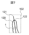
次に、各関心領域に対して、指の輪郭検知を実施する。図7は、指の輪郭と指先を検出する一実施例の説明図である。指の輪郭検知は、各関心領域内の画素値を判別分析に基づく2値化処理あるいはグラフカットなどの手法に基づき指と背景とを分けてその境界を取り出しても良く、また強いエッジを連結あるいは追跡する方式により取り出しても良い。このとき、隣の指が関心領域に含まれてしまう可能性もあることから、画像中心に近いほどエッジの重みを高くして、エッジの総量を最大化しながらエッジの距離や曲率を最小化する連結方法を採用しても良い。これにより、誤って隣の指の輪郭を抽出することが少なくなり、認証エラーを低減する効果が得られる。この処理によって、図7に示すように指輪郭120を獲得することができる。
Next, finger contour detection is performed on each region of interest. FIG. 7 is an explanatory view of an embodiment for detecting a contour of a finger and a fingertip. The contour detection of the finger may divide the finger and the background based on a method such as binarization processing based on discriminant analysis or graph cutting in the pixel value in each region of interest, and extract the boundary, and connect strong edges. Alternatively, it may be taken out by a tracking method. At this time, since there is a possibility that the adjacent finger may be included in the region of interest, the edge weight is increased closer to the center of the image to minimize the distance and curvature of the edge while maximizing the total amount of the edge. A connection method may be adopted. As a result, it is less likely to accidentally extract the contour of the next finger, and an effect of reducing an authentication error can be obtained. By this process,
各関心領域の指輪郭120が検出できると、次に指の中心線121を求める。指の中心線121は、指輪郭120を直線近似して求めても良く、あるいは抽出された指輪郭の内側領域を指領域と定義し、指領域の各画素を要素とした主成分分析を実施し、得られた第一主成分の方向(主方向)として求めても良い。次に、指輪郭120と指の中心線121とを用いて指先122を求める。これば、指の中心線と指の輪郭線の交点を指先122と定義してもよく、もしくは、関心領域102のy軸に向けて投影分布を算出し、画像の下側から上側に向けて輝度分布の値を調べ、はじめに背景であると判別できる閾値を下回ったy座標を指先と決めても良い。この方法では指輪郭を検出しなくても指先の大まかな位置を判定できるため、処理を簡素化し、高速化することが可能となる。
Once the
以上の処理により、各指のx座標、y座標、z座標の提示位置を検出し、また指輪郭と指先の位置を抽出できた。 By the above processing, the presentation position of the x coordinate, y coordinate, and z coordinate of each finger is detected, and the position of the finger contour and the fingertip can be extracted.
次に、指の距離・立体形状の計測結果を利用して、指の姿勢を検出する。指の姿勢は、指のx、y、z座標だけではなく、指の曲げや反り、そしてx、y、z軸の各軸を中心とした回転を含んでおり、これらの状態を検出することが必要となる。なお、指は2つの指関節によって3つの節に分けられるものとし、各節の中心軸を直線に近似した指の骨格構造を解析するものとする。また、図6(a)に示した座標系において、x軸、y軸、z軸の各軸を中心とした回転を、それぞれピッチング、ローリング、ヨーイングと定義する。 Next, the posture of the finger is detected by using the measurement result of the distance and solid shape of the finger. The posture of the finger includes not only the finger x, y, z coordinates, but also bending or warping of the finger and rotation about each of the x, y, z axes, and detecting these states Is required. In addition, a finger shall be divided into three clauses by two finger joints, and shall analyze the skeletal structure of a finger which approximated the central axis of each clause in a straight line. Further, in the coordinate system shown in FIG. 6A, rotation about each of the x-axis, y-axis and z-axis is defined as pitching, rolling and yawing, respectively.
図8は指の姿勢を検出する一実施例を示す。図8(a)に示す通り、この例では距離画像に対する関心領域102に2つの関節150を含む指1が撮影されており、指が軽く曲げられ、さらにローリングを含んでいる。提示された指の位置によっては、例示した図とは異なり関節が1つしか含まれない、あるいは関節がまったく含まれない場合も想定される。また指輪郭120の内側の領域は、明るいほどカメラに近い距離であるとする。まず、図8(b)に示すように距離画像を偏微分して各座標の法線ベクトル140を計算する。指1は楕円の円筒に類似する形状であるため、法線が放射状に分布していることが分かる。次に、図8(c)に示すように指の中心軸121が通る画素の法線ベクトルを調べる。この法線ベクトルを図8(d)に示す。指先や指の中節部などの膨らみによって、法線ベクトルは様々な方向を向く。このとき、関節150は窪みであるため、関節をまたぐ位置の法線ベクトルはその方向が交差する方向を向く。そこで、これらの法線ベクトルと指の中心軸121の成す角を求め、その方向が反転した位置を関節の推定位置151として検出する。最後に、関節の推定位置151によって分断された各節の領域について、すべての法線ベクトルと最も直交する方向を主成分分析より求め、これを節の中心軸152とする。このような処理により、指の節ごとの骨格構造を獲得することができる。 また、指のピッチングは節の中心軸152に沿った指内部領域の距離値の分布を直線近似し、その傾き角として求めることができる。またヨーイングは指の中心軸121の傾きから得られる。
FIG. 8 shows an embodiment for detecting the posture of a finger. As shown in FIG. 8A, in this example, the
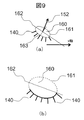
指のローリングについては、指の断面を楕円とみなし、観測できる部分の指表面の座標から楕円の長径と短径とを推定し、その長径方向とx軸との成す角度からローリング角を得ることができる。具体的には、まず図9(a)に示すように、ある注目画素163を通り、かつ、上記で求めた節の中心軸152と直交する指の断面160を定義すると、この断面と指表面とが成す曲線は楕円161となる。このとき、楕円161はすべて観測できている訳ではなく、映像として獲得できている複数の法線ベクトル140が分布している部分のみが観測されている。この部分に関しては、指の表面のx、y、zの各座標は既知である。つまり、楕円161の一部分のみが観測されている状態となっている。この部分曲線に対し、たとえばHough変換を適用することで、楕円161の長径162と短径の長さと向きとを獲得することができる。そして注目画素163を指の節の中心軸152に沿う方向に様々な位置に変えることによって多数の長径162が得られるが、求めたすべての長径162とx軸との成す角の平均値を求めることで、該当する指の節の平均的なローリング角が推定できる。最終的に、すべての節の平均的なローリング角を推定して平均すれば、その指の平均的なローリング角を得ることができる。
For finger rolling, consider the cross section of the finger as an ellipse, estimate the major axis and minor axis of the ellipse from the coordinates of the finger surface of the observable part, and obtain the rolling angle from the angle formed by the major axis direction and the x axis Can. Specifically, first, as shown in FIG. 9A, when a
上述した指の姿勢情報を獲得する別の実施例としては、指の姿勢情報が既知となる大量の指画像を教師データとし、Random forestなどの機械学習に基づいて、未知の距離画像から指の姿勢情報を推定しても良い。 As another example of acquiring finger posture information described above, a large amount of finger images for which finger posture information is known is used as teacher data, and based on machine learning such as Random forest, the finger distance information from unknown distance images is obtained. Posture information may be estimated.
以上より、各指のx、y、z軸の位置、指の曲げや反り、回転の状態を把握することができる。 From the above, it is possible to grasp the positions of the x, y and z axes of the fingers, the bending and warping of the fingers, and the state of rotation.
また、各指のx、y、z軸の位置、指の曲げ角度、回転角度を各フレームごとに時系列に蓄積し、それらの情報から指の位置や姿勢に関わる移動速度あるいは移動加速度を算出し、これらを指の姿勢判定に用いることもできる。たとえば、指が高速に移動していることを検知した場合は映像のぶれが生じるため、利用者に指を高速に動かさないように誘導したり、あるいは指がほとんど移動していない場合には偶然指が撮影されている可能性もあるため、指を動かすように促すことで認証していることを明示的に意思表示させることもできる。また、カメラから遠ざかる動作をさせた場合にのみ撮影を許容することで、被写体のぶれの傾向が概ね一致した画質の映像を撮影することができる。これにより登録時と入力時との画質が統一化されるため認証精度を向上することができる。 In addition, the position of x, y, z axes of each finger, the bending angle of the finger, and the rotation angle are accumulated in time series for each frame, and the movement speed or movement acceleration related to the position or posture of the finger is calculated from the information. These can also be used for finger pose determination. For example, when it is detected that the finger is moving at high speed, the image is blurred, so the user is guided not to move the finger at high speed, or when the finger is hardly moved, it happens accidentally Since there is a possibility that the finger has been photographed, it is also possible to explicitly indicate that authentication has been made by urging the finger to move. Also, by allowing shooting only when the user moves away from the camera, it is possible to shoot an image of an image quality that the tendency of blurring of the subject substantially matches. As a result, the image quality at the time of registration and at the time of input can be unified, so that the authentication accuracy can be improved.
次に、図3で示した手指を誘導するガイドの表示(S406)の一実施例について詳述する。上記のように指の提示位置や姿勢が検知できると、撮影されている指を適切な位置に誘導することが可能となる。 Next, one example of the display (S406) of the guide for guiding the finger shown in FIG. 3 will be described in detail. As described above, when the presentation position or posture of the finger can be detected, it is possible to guide the finger being photographed to an appropriate position.
図10は、認証に適した指の位置や姿勢を利用者に誘導するガイダンス画面の一実施例である。図10(a)は、認証に適した位置に指輪郭ガイド180を表示すると共に、指の提示を促すガイドメッセージ181を表示した状態である。この画面には、撮像装置で撮影された映像がオーバーラップして表示されており、利用者が操作しやすいように、利用者が右に指を動かすと映像の指も右側に動くように画像の左右反転処理を施している。なお、ここで表示する画像は左右カメラの画像を合成した距離画像としても良く、左または右カメラのどちらかの赤外光反射画像もしくは緑光反射画像としても良い。また生体情報の秘匿のため、指領域を塗りつぶしても良い。
FIG. 10 shows an example of a guidance screen for guiding the position and posture of a finger suitable for authentication to the user. FIG. 10A shows a state where a
利用者はこの表示に合せて指をかざす。しかしながら、指輪郭の概形はあらゆる指の形状に適合するものではないため、必ずしもかざした指の輪郭の形状と一致させることができるとは限らない。さらには、2次元平面的な位置合わせだけではなく、カメラ距離についても適切な位置に合せる必要があるため、表示されている指輪郭ガイドに一致するように指をかざしたとしても適切な提示位置にかざされているとは限らない。さらには、複数の指の位置を合せることは容易ではなく、すべての指が認証に適した位置に来るとも限らない。そのため、ガイド内容を順次変えながら誘導する必要がある。 The user holds his finger in line with this indication. However, since the outline of the finger contour does not conform to the shape of any finger, it can not necessarily match the shape of the contour of the finger that is held up. Furthermore, since it is necessary to adjust not only the two-dimensional planar alignment but also the camera distance to an appropriate position, an appropriate presentation position even if the finger is held to match the displayed finger contour guide It is not always held up. Furthermore, it is not easy to align the positions of a plurality of fingers, and not all fingers may be in positions suitable for authentication. Therefore, it is necessary to guide while changing the contents of the guide sequentially.
図10(b)は、3本指をかざしたときの一例を示す。まずは、上述の処理によって検出された3本の指のうち、中央に検出された指が画像の中心に位置するよう、左方向への指移動指示矢印182を表示する。これにより、指の全体的な位置合わせが実施できる。次に、図10(c)に示すように、中央の指が画像の中心に移動した状態であっても、左右の指が位置ずれを起こしているため、指を軽く閉じる旨を知らせると共に、各指の近くに右または左向きの指移動指示矢印182を表示して位置を誘導する。同様に、指が不自然に閉ざされている場合には、指を軽く開く旨の表示を行うこともできる。
FIG. 10B shows an example when holding three fingers. First, the finger
また図10(d)は、指が右にずれていて、かつローテーションを起こし、かつカメラ位置から近く、かつ関節が曲がっている状態を示す。まず指を左に移動するための矢印を表示し、続いてカメラ距離を離すためのカメラ距離指示アイコン183を表示する。その後、指のローテーションを元に戻すための回転指示アイコン184を表示する。最後に、指の関節を真っ直ぐに伸ばす旨を指示する。もしこのとき指先が画面の下に行き過ぎている場合はその旨を表示しても良い。
FIG. 10 (d) shows a state in which the finger is shifted to the right and is rotated, and is close to the camera position and the joint is bent. First, an arrow for moving the finger to the left is displayed, and then a camera
このように、まずは指の上下左右の位置やカメラ距離を誘導し、その後にピッチングなどの回転や指の曲げ伸ばしを誘導すると、大まかな提示位置から細かい調整の順に誘導でき、誘導の効率を高めることが可能となる。 As described above, when the first and second positions of the finger and the camera distance are guided and then the rotation such as pitching and the bending and stretching of the finger are guided, the guidance can be guided from the rough presentation position in the order of the fine adjustment. It becomes possible.
以上の通り、上述の姿勢検出結果に基づいて、指の提示位置と姿勢を正しい位置に誘導することができる。 As described above, based on the above-described posture detection result, the presentation position and the posture of the finger can be guided to the correct position.
なお、上述の実施例において適正な指の撮影本数は3本を想定したが、1本から5本までの間であれば撮影は実施してもよい。指の本数が多い場合は、最も右に位置する指と最も左に位置する指との平均位置が画像中央になるように誘導することで、かざした指全体を画角にバランス良く収められるように誘導できる。もしくは、現在かざされている指の本数をリアルタイムに検知し、各指の本数ごとに、上述の指輪郭ガイド180の表示本数を切り替えて適切な位置を示すこともできる。これらの処理により、複数指を効率良く提示でき、より高精度な複数指認証を実現できる。 In addition, although the number of imaging | photography numbers of the finger | toe suitable in the above-mentioned Example assumed three, imaging | photography may be implemented if it is between 1 and 5 pieces. When the number of fingers is large, guiding the average position of the rightmost finger and the leftmost finger to be at the center of the image allows the entire finger held to be balanced at the angle of view. Can be Alternatively, the number of fingers currently being held can be detected in real time, and the number of displayed finger contour guides 180 described above can be switched for each number of fingers to indicate an appropriate position. By these processes, a plurality of fingers can be efficiently presented, and more accurate multi-finger authentication can be realized.
次に、手指が適切な位置にあるかの判定ステップS407について述べる。認証に適した指の位置や姿勢は唯一に決定することはできるが、そこからのずれを許容しないと利用者は指の提示で時間が掛かり、利便性が低下する。そのため、撮影指の本数、指のx、y、zの位置、回転、曲げ伸ばし状態、などのパラメータに、理想状態からのずれ量に許容範囲を設け、すべてが許容範囲に入った時点で適切な姿勢であると判定する。なお、撮影指の本数について、たとえば3本を適正値とした場合、登録時は3本が画像に含まれるまで誘導し続けてデータ量を確保するようにするが、認証時は1本だけでも許容して良い。これは、ただ1本の一致でも確率的に明らかに本人であると判定できるケースがあるからであり、このようにすることで認証時の指の姿勢の制約を緩和でき、利便性の高い操作が実現できる。 Next, step S407 for determining whether the finger is at an appropriate position will be described. Although the position and posture of the finger suitable for authentication can be uniquely determined, if the user does not allow any deviation from it, the user takes a long time to present the finger and the convenience is degraded. Therefore, an allowance is provided for the amount of deviation from the ideal state in the parameters such as the number of shooting fingers, the x, y, and z positions of the fingers, the rotation, and the bending and stretching state, etc. It is determined that the posture is correct. In addition, when the number of photographing fingers is set to, for example, three as an appropriate value, at the time of registration, guidance is continued until three are included in the image to secure the data amount, but at the time of authentication It is good to accept it. This is because there is a case where even one match can be determined probabilistically and clearly as the correct person, by doing so it is possible to ease the restriction of the finger posture at the time of authentication, and a highly convenient operation Can be realized.
次に、指の切り出し処理ステップS408と立体補正処理ステップS409の一実施例について述べる。 Next, an embodiment of the finger cutout process step S408 and the three-dimensional correction process step S409 will be described.
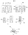
上述の通り指のガイダンスを実施した場合でも、利用者の利便性を考慮すると理想的な位置での撮影は難しく、従って指の姿勢変動が含まれる。この場合、姿勢の変動に伴う生体特徴の変形により、登録時のパターンと異なった特徴量が得られる。これに対し、たとえばSIFT特徴量などの変形にロバストな特徴量によって照合を実施するか、あるいは元画像の変形を補正するなどが必要となる。本実施例では、処理コストが小さいテンプレートマッチングによる照合を前提とし、指の姿勢情報(ここでは指先や関節、根元が手指の立体形状にラベリングされた状態を意味する)の検出結果を利用し、撮影されている2次元平面の生体画像を幾何学変換し、正規化した状態に補正する。 As described above, even when finger guidance is performed, photographing at an ideal position is difficult in consideration of the convenience of the user, and thus includes finger posture variations. In this case, due to the deformation of the biological feature accompanying the change in posture, a feature amount different from the pattern at the time of registration can be obtained. On the other hand, for example, it is necessary to carry out matching using feature quantities that are robust to deformation such as SIFT feature quantities or to correct deformation of the original image. In this embodiment, on the premise of matching by template matching having a low processing cost, detection results of finger posture information (here, a state in which a finger tip, a joint, and a root are labeled in a three-dimensional shape of a finger) are used. The biological image of the two-dimensional plane being photographed is geometrically transformed and corrected to a normalized state.
まず、図11(a)に示すように距離画像100に対して決定した関心領域102について、図11(b)に示すように赤外光反射画像および緑光反射画像200について上述で求めた指先位置を基準とした指の切り出し画像201を生成する。これにより、指先が切り出し画像201の上辺に接するようになり、x軸およびy軸の位置ずれが補正される。なお、上述で求めた指先位置、指輪郭、指の節ごとの中心軸などの姿勢情報は距離画像100に対して求めたものであり、左右2つのカメラにより撮影された反射画像の座標系に対するずれが存在する。ここで、距離画像100と反射画像200との間の座標系のずれはキャリブレーション可能であるとし、座標変換によって求められるものとする。座標変換に誤差が生じる場合には、距離画像で求めた指輪郭を反射画像上で平行移動させながら指輪郭の存在する全画素のエッジ総量を計測し、指輪郭上のエッジ総量が最も多くなる場所に位置補正し直しても良い。また反射画像200は左右いずれのカメラの画像でも良く、左右両方の画像を合成した画像でも良い。いずれの場合においても座標変換が可能であるものとする。
First, for the region of
次に、図11(c)に示すように、切り出し画像201に映る指の輪郭に対し、距離画像で得た指の距離値が一定になるように画像のサイズを拡大または縮小する。拡大率の計算は、最適な距離値と現在の指の距離値との比率によって決定する。これにより、z軸方向のずれがあっても、指のサイズを一定に保つことができる。このとき、指の部分領域の距離値が一定になるよう、画像を部分的に拡大または縮小することで、指のピッチング角度による距離の不均一性も解消できる。
Next, as shown in FIG. 11C, the image size is enlarged or reduced such that the distance value of the finger obtained in the distance image becomes constant with respect to the contour of the finger shown in the
そして、図11(d)に示すように、指の節ごとの中心軸152が画像の上方を向くように回転補正する。中心軸152は指の節ごとに傾きが異なる場合があるため、節ごとの中心軸の平均値を求めて、それが画像の上方を向くように回転補正しても良い。
Then, as shown in FIG. 11 (d), rotation correction is performed so that the
最後に、図11(e)に示すように、上述で求めた指の断面の楕円161とその長径162が画像のx軸に平行になる向きに2次元平面の座標を投影変換する。ここでは投影変換後のx軸をx’軸と図示するが、以降はこれもx軸と呼称する。これにより、ローリングによって指の2次元画像の見え方が変形しても、指の腹側が正面を向いた投影像に変換されるため、変形のない映像が得られる。
Finally, as shown in FIG. 11E, the coordinates of the two-dimensional plane are projected and transformed in a direction in which the
以上の処理により、指のx、y、z軸の座標と、回転方向の補正が実施できる。なお、ここで示した補正は、後述の特徴抽出処理の後に実施しても同様の効果が得られる。 By the above-described processing, correction of the x-, y-, and z-axis coordinates of the finger and the rotational direction can be performed. The same effect can be obtained even if the correction shown here is performed after feature extraction processing described later.
最後に、特徴抽出処理(S410)、照合処理(S411)、そして判定処理(S412)について述べる。特徴抽出処理は、赤外反射画像と緑反射画像の2枚についてそれぞれ特徴量を抽出する。赤外反射画像には静脈などの情報が、また緑反射画像には指紋、関節しわ、脂肪紋などが確認されるため、一般的な静脈パターンの抽出処理やテクスチャパターンの抽出処理を実施して、生体特徴を獲得する。特に線パターンを鮮鋭化するために、アンシャープマスク処理を前処理として実施しても良い。なお、映像は左右のカメラの2つがあるが、片方のカメラの映像だけを用いても良く、両方の映像を用いて別途特徴抽出を実施し、最後に得られたパターンを合成しても良く、また合成せずにそれぞれ独立したパターンとして活用しても良い。いずれにしても、両方の映像は視差を持ち、異なった情報として利用できるため複数のカメラの映像を利用することで精度向上が見込まれる。照合処理に関しては、抽出されたパターンを一般的なテンプレートマッチングあるいは特徴点マッチングの手法により類似度を判定する。そして、得られた類似度が事前に決定した閾値を下回った場合に認証成功となる。なお、赤外画像や緑画像、複数のカメラの映像を用いることで複数の生体特徴が得られるが、すべてを照合したときの平均的な類似度や、類似度の高い複数の結果の平均的な類似度により、認証の判定を実施しても良い。複数の類似度を算出した方がデータの冗長性が高まり、精度向上に寄与する。 Finally, the feature extraction process (S410), the matching process (S411), and the determination process (S412) will be described. The feature extraction processing extracts feature amounts for each of the infrared reflection image and the green reflection image. Since information such as veins is confirmed in the infrared reflection image, and fingerprints, joint wrinkles, fat marks and the like are confirmed in the green reflection image, general vein pattern extraction processing and texture pattern extraction processing are performed. , Acquire biometric features. In particular, in order to sharpen the line pattern, unsharp mask processing may be performed as preprocessing. Although there are two video images for the left and right cameras, it is also possible to use only the video from one camera, or separate image extraction may be performed separately using both videos, and the pattern obtained at the end may be synthesized Alternatively, they may be used as independent patterns without being synthesized. In any case, since both videos have parallax and can be used as different information, accuracy improvement can be expected by using videos of a plurality of cameras. With regard to the matching process, the extracted pattern is determined for similarity by general template matching or feature point matching. Then, when the obtained degree of similarity falls below a predetermined threshold, the authentication is successful. In addition, although a plurality of biometric features can be obtained by using infrared images, green images, and images of a plurality of cameras, it is possible to obtain an average similarity of all when compared, or an average of a plurality of high similarity results. The determination of authentication may be performed based on the degree of similarity. Calculation of a plurality of similarities increases data redundancy and contributes to accuracy improvement.
次に、登録時の誘導方法と認証時の誘導方法についての差異について詳述する。
登録時においては、できるだけ安定した状態で生体を撮影することが望ましい。そのため、生体の撮影状態が良くなるように、理想的な提示位置まで誘導を続けた上で登録データを作成する。たとえば、撮影する生体ができるだけ中心に映ること、できるだけ広い範囲を撮影すること、指の回転が少なくカメラに正対していること、設定したカメラの被写界深度に含まれること、指が曲がっていないこと、などを満たすように指を誘導する。
Next, the difference between the guiding method at registration and the guiding method at authentication will be described in detail.
At the time of registration, it is desirable to photograph the living body in a state as stable as possible. Therefore, registration data is created after continuing guidance to an ideal presentation position so that the imaging | photography state of a biological body may become good. For example, the living body to be photographed appears as central as possible, photographing a wide area as much as possible, that the rotation of the finger is small and facing the camera, included in the set depth of field of the camera, the finger bent Guide your finger to meet that, etc.
しかしながら、中空で指の位置を厳密に合せることは難しく、利用者によっては理想的な提示位置に静止することができない場合も想定され、利便性が劣化する。そこで、誘導はある一定の余裕を持たせることが必要である。 However, it is difficult to exactly match the position of the finger in a hollow position, and it may be assumed that some users can not stop at the ideal presentation position, and the convenience deteriorates. Therefore, the induction needs to have a certain margin.
また、上述の通り、撮影した画像を幾何学的に補正した場合であっても、実際に手指の位置が変化したときに同様な画質の映像が撮影できるとは限らない。そのため、様々な指の姿勢となる複数枚の登録データを獲得し、照合の際にはすべての登録データとの照合を行って複数の類似度を獲得し、これらに基づいて最終的な認証判定を実施する。この方法は、登録データが様々な指姿勢のバリエーションを有するため、姿勢の変動にロバストな認証を行うために有効である。このとき、登録時の指の誘導の際に、指の誘導の基準が同じであると常に一定の指姿勢の撮影だけ実施されるため、指姿勢にバリエーションが含まれにくくなる。 Further, as described above, even when the captured image is geometrically corrected, it is not always possible to capture an image of the same image quality when the position of the finger actually changes. Therefore, a plurality of registration data with various finger postures are acquired, and at the time of collation, collation with all the registration data is performed to acquire a plurality of similarities, and based on these, the final authentication judgment Conduct. This method is effective for performing robust authentication against posture variations because the registration data has various finger posture variations. At this time, when guiding the finger at the time of registration, if the reference of guiding the finger is the same, only shooting of a constant finger posture is always performed, and it becomes difficult to include variations in the finger posture.
そこで、はじめの一枚は、上述の通り最も画質が高まる位置に撮影されるように誘導し、次にカメラからやや近い、拡大率の高い位置で撮影する。最後に、指がカメラから遠ざかった位置で撮影する。この3枚を登録すると、認証時にかざした指が標準位置に対してカメラから近づいたり遠ざかったりする変動が生じても、いずれの1枚がより類似度が高まる。その結果、拡大率の変動にロバストな照合を実現することができる。 Therefore, the first one is guided so as to be photographed at the position where the image quality is the highest as described above, and then photographed at a position where the magnification ratio is a little close to the camera. Finally, shoot with the finger away from the camera. If these three sheets are registered, even if a finger held at the time of authentication changes so as to approach or move away from the camera with respect to the standard position, any one sheet has higher similarity. As a result, robust matching can be realized against fluctuations in magnification.
同様に、標準位置に誘導する場合と、標準位置より左に誘導する場合と、標準位置より右に誘導する場合との3通りを撮影するなど、指の姿勢について様々な組合せを取ることができることはいうまでもない。カメラの特性や装置の形状に応じて生体の変動がより大きくなる指姿勢が考えられるため、変動の大きい指の姿勢に誘導するとより効果的である。このような誘導により、指の姿勢変化にロバストな認証を実現できる。 Similarly, it is possible to take various combinations of finger postures, such as photographing in three cases of guiding to the standard position, guiding to the left from the standard position, and guiding to the right from the standard position. Needless to say. Since it is possible to consider finger postures in which the fluctuation of the living body becomes larger according to the characteristics of the camera and the shape of the device, it is more effective to guide the finger postures with large fluctuation. Such guidance can realize robust authentication against finger posture change.
一方、認証時においては、厳密な位置合わせを要求することで操作時間が長くなったり位置合わせの煩わしさが発生したりすることで利便性が低下する。そのため、登録時よりも誘導ずれの許容量を大きく取り、指の姿勢情報に基づいて補正を行うことでその位置ずれを吸収する。このとき、リアルタイムに画像を撮影して照合が実施できるシステム構成であれば、手をかざしている間のどこかで登録データに近い指の姿勢となれば認証が成功するため、比較的位置ずれを許容しても正しく認証できる。そのため、手指が適切な位置にない場合であっても認証処理は実施し、画面に位置がずれている旨を表示するように処理フローを変更しても良い。 On the other hand, at the time of authentication, by requiring strict alignment, the operation time becomes longer and inconvenience of alignment occurs, which reduces the convenience. Therefore, the allowable amount of induction deviation is taken larger than at the time of registration, and the position deviation is absorbed by performing correction based on the posture information of the finger. At this time, in the case of a system configuration capable of capturing an image in real time and performing verification, if the finger posture close to the registered data is achieved somewhere while holding up the hand, authentication succeeds, so the positional deviation is relatively Can be correctly authenticated even if Therefore, even if the finger is not at the appropriate position, the authentication process may be performed, and the processing flow may be changed so as to display that the position is shifted on the screen.
以上により、登録時は品質の高い生体を撮影でき、認証時は利便性の高い操作で認証処理を実施することが可能となる。 As described above, it is possible to capture an image of high quality at the time of registration, and to perform an authentication process by a highly convenient operation at the time of authentication.
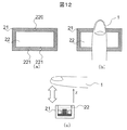
図12は、指の位置を容易に誘導する認証装置の構成と操作方法の一実施例を示す図である。非接触撮影を実施するにおいては、空中に指をかざすため、カメラがどの辺りを撮影しているかは画面を確認しないと分かりにくく、また適切なカメラからの距離も把握しにくい。そこで、図12(a)に示すように、装置筺体21に指先ガイドマーク220および指根元ガイドマーク221を設置する。ガイドマークは三角形で示されており、三角形の頂点の向きが指先側を示している。これにより、装置と指との向きの関係性を示すことができる。なお、これらの印は指の向きと方向とが示されれば良く、形状は三角形に限定されるものではない。
FIG. 12 is a diagram showing an example of the configuration and operation method of the authentication device for easily guiding the position of the finger. When performing non-contact shooting, since the finger is held in the air, it is difficult to know which area the camera is shooting without checking the screen, and it is also difficult to grasp the distance from the appropriate camera. Therefore, as shown in FIG. 12A, the
図12(b)に示すように、利用者は指先ガイドマーク220に指1の指先を置き、2つの指根元ガイドマーク221の間に入るように指根元を置く。次に図12(c)に示されるように指を装置から遠ざける。このように、最初に指を装置筺体21に接触させ、そこから指を遠ざける操作を行うと、カメラの光軸中心やカメラからの最適距離を通過する可能性が高まり、より品質の高い生体の撮影が実現できる。なお、本実施例ではガイドマークを筺体の中心に配置しているが、カメラの位置や撮影する指本数などに応じて、指が適切な撮影位置に移動しやすいように配置しても良い。また、ガイドマークは装置筺体21に指の形に合せて形成された窪みとし、その場所に指が置かれるようにしても良い。
As shown in FIG. 12B, the user places the fingertip of the
装置にガイドマークが配置された非接触認証装置の処理フローの一例を以下に示す。まず、システムが「装置に指を乗せてください」と利用者にガイダンスを行う。そして、光源を点灯し、画像を連続撮影しながら生体の提示を待つ。もし生体が指置き台に置かれると、光源の強い反射光により画像が飽和する。画像が輝度飽和するかどうかは光源と指との距離によって決まるため、指を装置筺体21に載せた時の平均輝度値を事前に調べておき、指が置かれたかどうかを判定する閾値処理を定めて置くことで指の設置を判定することができる。利用者がガイドマークに合せて指を置くと、指の設置判定処理によって指が置かれたと判定される。
An example of the process flow of the non-contact authentication apparatus in which a guide mark is arranged in the apparatus is shown below. First, the system gives guidance to the user, "Please put your finger on the device". Then, the light source is turned on to wait for the presentation of a living body while continuously capturing images. If the living body is placed on the finger rest, the image is saturated due to the strong reflected light of the light source. Since whether or not the image is saturated is determined by the distance between the light source and the finger, threshold processing is performed to determine in advance the average luminance value when the finger is placed on the
続いてシステムは「指を遠ざけてください」と利用者にガイダンスを行う。これに応じて、図12(c)に示すように利用者が指を装置から遠ざけると、徐々に反射光の強度が小さくなり、指と装置とが離れたことが分かる。そして、上述の距離計測処理を実施し、指が適切な距離にあることが検知できると、その時の画像から生体の特徴量を抽出する。登録処理であればその生体特徴を登録し、認証処理であればその生体特徴を入力として登録データとの照合を行う。 Then the system gives guidance to the user saying "Please keep your finger away". Accordingly, as shown in FIG. 12C, when the user moves the finger away from the device, the intensity of the reflected light gradually decreases, and it can be seen that the finger and the device are separated. Then, the above-described distance measurement process is performed, and when it is detected that the finger is at an appropriate distance, the feature amount of the living body is extracted from the image at that time. In the case of the registration process, the biometric feature is registered, and in the case of the authentication process, the biometric feature is used as input to collate with the registration data.
本実施例によると、指のガイドマークに指を置くことで、指が画角から大きく外れたり、カメラからの適切な撮影距離から大きく外れたりすることなく生体を撮影できるため、利用者が指を空中に静止させず、一連の操作の中で最適な撮影画像を決定できるという効果が得られる。 According to the present embodiment, by placing the finger on the guide mark of the finger, the user can photograph the living body without the finger being largely deviated from the angle of view or the appropriate photographing distance from the camera. There is an effect that it is possible to determine an optimum photographed image in a series of operations without stopping the camera in the air.
なお、上述した登録時の誘導方法の実施例で示した通り、登録データを複数獲得する際の登録試行回数に応じて最適な撮影距離の閾値を変化させ、登録データには距離の異なる複数の登録データが含まれるようにしても良い。これにより、認証時に指の距離が変化しても登録データとの類似性を維持することが可能となる。 Note that, as described in the example of the guidance method at the time of registration described above, the threshold value of the optimum photographing distance is changed according to the number of registration trials when acquiring a plurality of registration data. Registration data may be included. This makes it possible to maintain the similarity to the registered data even if the distance of the finger changes at the time of authentication.
指の位置を容易に誘導する認証装置の別の操作方法として、装置をタッピングする方法がある。上述の指を遠ざける操作は、装置を固定するか一方の手で保持した状態でなければ実施することは難しい。そこで、指を遠ざける操作の代わりに、装置を片手で保持し、同じ手の指先を所定の位置に設置した状態から、一定の距離を遠ざけてまた元に戻すといった、上下方向のタッピングを行う。これにより、片手の操作だけで最適なカメラ距離となる生体画像を撮影できる。 Another method of operating the authentication device for easily guiding the position of the finger is to tap the device. The above-mentioned finger-removing operation is difficult to perform unless the device is fixed or held by one hand. Therefore, instead of the operation of moving the finger away, tapping in the vertical direction is performed such that the device is held with one hand and the fingertip of the same hand is placed at a predetermined position, and then the fixed distance is moved back again. As a result, it is possible to capture a living body image with an optimal camera distance only by one-handed operation.
図13(a)に示すように、まず利用者は装置筺体21を握り、たとえば人差し指240を指先のガイドマークに置く。システムから指をタップする旨の指示が出ると、利用者はタップを開始する。タップ時は指の向きが図13(b)に示されるように斜めの提示となるため、撮影された指画像もピッチングが生じた状態で撮影される。しかし指全体が画像の画角に収まる適切な角度であり、かつ登録データが同様な姿勢で保存されているのであれば認証に利用しても差し支えない。そこで、指を上下する操作を何回か繰り返し、指が画角に収まるタイミングで数枚の撮影を実施する。そしてこれらの画像から生体の特徴データを生成して登録を行う。認証時も同様の操作を行うと、登録時の状態に近い指姿勢となった瞬間に登録データとの類似性が高まって認証が成功する。
As shown in FIG. 13 (a), the user first grasps the
このように、タッピング操作を行うことで、指の提示位置が一定の範囲に収められるため登録データとの再現性が高くなる上に、空中で指の位置合わせを実施することなく容易に空中の指を撮影でき、さらに片手で装置を持ちながら認証を実施することが可能となるため、装置の利便性が向上する。 In this way, by performing the tapping operation, the presentation position of the finger is contained within a certain range, so that the reproducibility with the registered data is enhanced, and the finger is easily positioned in the air without performing the alignment of the finger in the air. Since it is possible to take a finger and to carry out authentication while holding the device with one hand, the convenience of the device is improved.
図14は、第2の実施の形態である、赤外光を発光する光源とひとつの赤外カメラで構成された反射非接触生体認証装置の一実施例である。 FIG. 14 shows an embodiment of a reflection non-contact biometric authentication device constituted by a light source emitting infrared light and one infrared camera according to the second embodiment.
撮像装置9の周囲に赤外光源31が複数個並べられており、赤外光源31が発光する波長付近のみの光を通過させるバンドパスフィルタ33が撮像装置9のレンズ部に搭載されている。撮像装置9は赤外カメラであり、指1で反射した光を撮影することができる。
A plurality of infrared
図15は当該実施例における処理フローの一実施例である。これは上述した実施例1の図3に示した処理フローとほぼ同様である。ただし、上述との差異は、2台のカラーカメラではなく1台の赤外カメラを用いる点、ステレオ視による距離計測を実施しない点、複数波長ではなく単一波長の画像を用いる点、である。以下、処理フローの概要を説明する。 FIG. 15 shows an example of the process flow in this embodiment. This is substantially the same as the processing flow shown in FIG. 3 of the first embodiment described above. However, the difference from the above is that one infrared camera is used instead of two color cameras, no distance measurement with stereo vision is performed, and a single wavelength image is used instead of multiple wavelengths. . The outline of the processing flow will be described below.
まず、システムが利用者に対して指の提示を促す(S501)。続いて赤外光を照射しながら1台の赤外カメラで撮影を開始する(S502)。このとき外光が強い場合は露光調整も実施する。続いて撮影された映像から被写体の距離・立体形状推定を実施する(S503)。もし認証装置から予め設定した距離の範囲内に被写体が存在するかを判定し(S504)、存在しない場合は生体が提示されていないものとみなし、生体が提示されるまで待つ。一方、所定距離の範囲内に被写体がある場合は生体が提示されたものとみなし、手指の姿勢検知処理を実施する(S505)。次に、姿勢判定結果を用いて指の誘導処理を行う(S506)。このとき指の位置や角度が想定からずれていたり、指が不適切に曲げられていたりする場合は、適切な撮影状態となるよう画面表示やガイドLED、ブザーなどを用いて利用者を誘導し、姿勢判定と誘導を反復して行う。一方、適切な姿勢と判定された場合は(S507)、指の姿勢情報に基づいて指画像の切り出し処理を実施する(S508)。指の姿勢情報には、指先や指の根元の位置が含まれており、認証の対象となる1本ないし複数本の指の位置情報を用いてそれぞれの画像を切り出す。そして、切り出された指画像に対して指の位置や向き、距離に応じて画像の拡大率の補正し、指の姿勢を正規化する(S509)。続いて、姿勢が正規化された指画像から生体特徴を抽出する(S510)。その後、生体特徴を照合し(S511)、登録データとの類似度を算出して、利用者が登録者であるかどうかを判定する(S512)。 First, the system prompts the user to present a finger (S501). Subsequently, imaging is started with one infrared camera while emitting infrared light (S502). At this time, if the external light is strong, exposure adjustment is also performed. Subsequently, distance and solid shape estimation of the subject is performed from the photographed image (S 503). If it is determined that the subject is present within the range of the distance set in advance from the authentication device (S504), it is regarded that the living body is not presented and waits until the living body is presented. On the other hand, if the subject is within the range of the predetermined distance, it is considered that the living body is presented, and the posture detection process of the finger is performed (S505). Next, a finger guidance process is performed using the posture determination result (S506). At this time, if the position or angle of the finger deviates from the assumption, or if the finger is bent improperly, guide the user using the screen display, guide LED, buzzer, etc. so as to obtain an appropriate shooting state. Perform posture determination and guidance repeatedly. On the other hand, when it is determined that the posture is appropriate (S507), the finger image cutout processing is performed based on the finger posture information (S508). The posture information of the finger includes the position of the fingertip or the root of the finger, and the image of each finger is cut out using the positional information of one or more fingers to be authenticated. Then, the enlargement ratio of the image is corrected according to the position, the direction, and the distance of the finger with respect to the extracted finger image, and the posture of the finger is normalized (S509). Subsequently, a biological feature is extracted from the finger image whose posture is normalized (S510). Thereafter, the biometric feature is collated (S511), the similarity to the registered data is calculated, and it is determined whether the user is a registrant (S512).
ここで、本実施例である図15と、上述の第一の実施例である図3との差異が存在する処理ブロックについて詳述する。 Here, processing blocks in which there is a difference between FIG. 15 which is the present embodiment and FIG. 3 which is the first embodiment described above will be described in detail.
まず、赤外光の照射とカメラでの撮影処理(S502)について述べる。生体認証装置を実運用する場面において、撮影装置の周囲には様々な物体が存在する。そのため、赤外反射画像の撮影においては、手指以外の不要な被写体が撮影されることも多い。不要な被写体は手指を正しく検出するためのノイズとなることがあるため、より高精度な認証を行うためには不要な被写体を除去する必要がある。その一方法としては図14で示した通り、光源31の波長のみを透過するバンドパスフィルタ33を搭載する方法がある。一方、環境に同じ波長域の反射光が存在する場合はその成分を除去することはできない。そこで本実施例では、光源の点灯画像と消灯画像との差分により背景除去を行う。
First, the irradiation of infrared light and the photographing process (S502) by the camera will be described. In a scene where a biometric authentication device is put to practical use, various objects exist around the imaging device. Therefore, when photographing infrared reflection images, unnecessary subjects other than fingers are often photographed. Unnecessary subjects may be noise for correctly detecting fingers, and therefore it is necessary to remove unnecessary subjects in order to perform more accurate authentication. As one of the methods, as shown in FIG. 14, there is a method of mounting a
まず光源31を消灯した画像を撮影する。そしてその直後に光源31を点灯した画像を撮影する。そして、点灯時に撮影した画像から消灯時に撮影した画像を差し引くと、かざした手指の映像は残されたまま、光源31とは無関係に明るく映る不要な被写体の成分を除去することができる。これにより、外光の影響によらず手指の切り出しを正確に実施できる。また、もし指表面に外光成分が照射されている場合は差分の計算によりキャンセルされるため、後述する姿勢検知処理の外光に起因する誤作動も低減することができる。
First, an image with the
また、光源を消灯した画像が極めて明るい場合には、外光が強く照射されていることが分かる。このとき、その明るさに応じて光源を強く照射すると共にカメラの露光時間を短く制御することで、強い外光が照射されている環境においても生体の計測が実現できる。露光を調整する場合は、後述する手指の姿勢検知処理などにおいて処理に必要な最適パラメータが変化するため、各処理においてそれぞれの露光時間に対する最適なパラメータを予め求めておく。 Moreover, when the image which turned off the light source is very bright, it turns out that external light is irradiated strongly. At this time, by irradiating the light source strongly according to the brightness and controlling the exposure time of the camera to be short, measurement of the living body can be realized even in an environment where strong external light is irradiated. When adjusting the exposure, since the optimum parameters necessary for processing change in the posture detection processing of the finger or the like described later, the optimum parameters for the respective exposure times are determined in advance in each processing.
このように、本実施例では光源の点滅による背景差分により不要な背景を除去し、指の検出精度を向上できる。ただしこの手法は撮影のためのフレームレートが半減するため、フレームレートが十分に高くない場合はバンドパスフィルタ33による不要背景の除去を実施するか、指と背景とが分離済みの赤外反射画像を事前に大量に獲得しておき、Random forestなどの機械学習によって指と背景とを分離する手法を適用することもできる。
As described above, in the present embodiment, an unnecessary background can be removed by the background difference due to the blinking of the light source, and the finger detection accuracy can be improved. However, this method reduces the frame rate for shooting by half, so if the frame rate is not high enough, use the
次に、被写体の距離・立体形状の計測(S503)について詳述する。本実施例は、上述の実施例のようにステレオ視による距離計測が実施できないため、1台の赤外カメラで距離計測を実施する必要がある。 Next, measurement of the distance and solid shape of the subject (S503) will be described in detail. In this embodiment, since distance measurement by stereo vision can not be performed as in the above-described embodiment, it is necessary to perform distance measurement with one infrared camera.
1台の赤外カメラで距離推定を行う方法として、照射した反射光の光強度に関する逆二乗の法則を用いるものがある。光源はカメラの周辺に設置されているため概ね点光源であるとみなせることから、指に向けて放出される光は球体状に広がっていく。球の表面積は球の半径の2乗に比例して大きくなるため、単位面積当たりの光のエネルギーは半径の2乗に反比例する。そのため、被写体の明るさは、被写体の反射率と吸収率、そして被写体とカメラとの距離によって決まる。 As a method of performing distance estimation with one infrared camera, there is a method using the inverse square law with respect to the light intensity of the reflected light irradiated. Since the light source is placed around the camera and can be regarded as a point light source in general, the light emitted toward the finger spreads like a sphere. Since the surface area of a sphere increases in proportion to the square of the radius of the sphere, the energy of light per unit area is inversely proportional to the square of the radius. Therefore, the brightness of the subject is determined by the reflectance and absorption rate of the subject, and the distance between the subject and the camera.
照射する光量をIi、皮膚での反射・吸収係数をμ、被写体までの距離をD、受光する光量をIoとする。また、指表面の反射光はランバート反射であり、反射光が等方的に拡散すると仮定すれば、以下の近似式が成立する。 The light quantity to be irradiated is Ii, the reflection / absorption coefficient on the skin is μ, the distance to the subject is D, and the light quantity to receive light is Io. Further, assuming that the reflected light on the finger surface is Lambertian reflection and the reflected light diffuses isotropically, the following approximate expression holds.
ここで、照射光強度Iiや皮膚での平均的な反射強度μは事前に調査できるため、距離Dについて解くことで画像の各画素の距離を把握することができる。ただし、照射光量と受光光量は画像の輝度値として検出するが、直接Iiを輝度値として計測すると一般的には輝度が飽和するため、減衰率が既知となるフィルタで照射光量Iiを物理的に減衰させた状態でその映像を撮影し、減衰させた分だけ光量Iiを増加させるなどのキャリブレーションを実施しておく。もしくは、装置内に照射光Iiを直接反射するミラーなどを搭載し、上述の減衰率が既知となるフィルタを介して照射光Iiを直接観測できるように構成しても良い。この手法により、かざされた手指の輝度値から距離画像を獲得することができる。 Here, since the irradiation light intensity Ii and the average reflection intensity μ on the skin can be investigated in advance, the distance of each pixel of the image can be grasped by solving for the distance D. However, although the amount of irradiated light and the amount of received light are detected as the luminance value of the image, the luminance is generally saturated if Ii is directly measured as the luminance value, so the irradiated light amount Ii is physically determined by a filter whose attenuation factor is known. The image is photographed in the attenuated state, and calibration such as increasing the light amount Ii by the attenuated amount is performed. Alternatively, a mirror or the like that directly reflects the irradiation light Ii may be mounted in the apparatus so that the irradiation light Ii can be directly observed through the filter whose attenuation factor is known. By this method, it is possible to obtain a distance image from the luminance value of the finger that is held up.
また、距離が正確に測定できるカメラと本実施例の撮像装置とを併設して指を撮影し、距離の正解ラベルを各画素に割り当てた学習データを大量に収集し、たとえばRandom Forestなどの機械学習に基づいて、赤外反射画像から指の距離画像を求めても良い。 In addition, a camera capable of accurately measuring the distance and the imaging device of the present embodiment are juxtaposed to capture a finger, and a large amount of learning data in which the correct distance label is assigned to each pixel is collected. Based on the learning, a distance image of the finger may be determined from the infrared reflection image.
ただし、実際には外光などの影響で想定より明るい映像が撮影される可能性もある。その場合は距離Dの絶対値に誤差が含まれる。そこで、画像の任意の位置にある被写体の距離を1とした、相対的な距離分布を求めることで、被写体の立体構造を把握することも可能である。また、事前に画像の輝度値と距離値の大まかな変換表を作成しておき、前記任意の位置にある被写体の画素における輝度値からこの距離値を読み取り、画像全体の相対距離値にこの距離値を乗算することで、大まかな距離画像を得ることもできる。 However, there is also a possibility that an image brighter than expected may actually be taken due to the influence of external light and the like. In that case, the absolute value of the distance D includes an error. Therefore, it is also possible to grasp the three-dimensional structure of the subject by obtaining a relative distance distribution, where the distance of the subject at an arbitrary position of the image is 1. In addition, a rough conversion table of the luminance value and the distance value of the image is prepared in advance, this distance value is read from the luminance value of the pixel of the subject at the arbitrary position, and this distance value is used as the relative distance value of the entire image. Rough value images can also be obtained by multiplying the values.
次に、手指の姿勢検知(S505)について、実施例1との差異を述べる。ここでは、上述した距離画像を獲得する方法を用いて実施例1と同様の処理を実施しても良いが、さらに簡便な手法として、赤外反射画像を距離画像に変換せずに手指の姿勢検知を行う実施例を示す。 Next, the difference from the first embodiment will be described with regard to finger posture detection (S505). Here, the same processing as in the first embodiment may be performed using the method of acquiring the distance image described above, but as a simpler method, the posture of the finger is not converted to the distance image in the infrared reflection image. The example which detects is shown.
まず、赤外反射画像を距離画像とみなし、実施例1の図6で示した手法により関心領域102を獲得しておく。ただし反射画像の輝度値が高いほど距離が近いとみなす。
First, the infrared reflection image is regarded as a distance image, and the region of
まず指のx軸方向の位置検出に関しては、実施例1の図6で示した通り、赤外反射画像を距離画像とみなして関心領域を決定する際に得られるx軸方向の座標より獲得できる。また指のy軸方向の指先の位置検出に関しては、図7で示した同様の方法で獲得できる。またカメラとの距離(z軸の位置検出)に関しては、反射画像の明るさと光源距離との間には逆二乗の法則が成立し、両者には相関があることから、ある光量値を発光させたときの指の平均輝度とカメラ距離との関係を事前に調べておくことで、平均輝度からカメラ距離への変換表を作成することができる。そして入力された指の輪郭検出を実施した際に指内部の平均輝度を求め、前記変換表を用いてこの平均輝度値からカメラ距離を算出する。これにより、輝度値が明るすぎる場合は指がカメラに近づきすぎており、逆に輝度値が暗すぎる場合は指がカメラから離れすぎていることが検知できる。外光の影響でこの値は変化するが、光源消灯時の画像を撮影しておくことで外光による輝度を把握しておけば、その値を差し引くことで外光の影響を緩和できる。 First, with regard to position detection in the x-axis direction of the finger, as shown in FIG. 6 of the first embodiment, the infrared reflection image can be obtained from the coordinates in the x-axis direction obtained when determining the region of interest by regarding it as a distance image. . Further, the position detection of the finger tip in the y-axis direction can be obtained by the same method as shown in FIG. With regard to the distance to the camera (position detection of z axis), the law of inverse square holds between the brightness of the reflected image and the light source distance, and there is a correlation between the two, so By examining in advance the relationship between the average luminance of the finger and the camera distance, it is possible to create a conversion table from the average luminance to the camera distance. Then, when detecting the contour of the input finger, the average luminance inside the finger is obtained, and the camera distance is calculated from the average luminance value using the conversion table. This makes it possible to detect that the finger is too close to the camera when the luminance value is too bright, and that the finger is too far from the camera when the luminance value is too dark. Although this value changes due to the influence of external light, if the brightness due to the external light is grasped by photographing the image when the light source is off, the influence of the external light can be mitigated by subtracting the value.
ヨーイングの検出に関しては、図7で示される上述の手法と同様に、指の中心軸121を求めてこの軸が画像y軸に平行となるように回転補正を施す。
As to the detection of the yawing, as in the above-described method shown in FIG. 7, the
またピッチングの検出に関しては、図16に検出方法の一実施例を示す。この例では、指先がカメラから遠ざかる方向にピッチング回転を起こしているものとする。まず、赤外反射画像に映る指の切り出し画像300に対しy軸に向けて平均輝度投影分布301を算出する。ここでは座標yの平均輝度投影分布をIave(y)と表記する。指先がカメラから遠いため、Iave(y)は指先付近の値が低い。なお、反射画像は指の細かい凹凸や血管の有無に起因する輝度変化を伴うため、Iave(y)にも細かい起伏が観測される。次に、以下の式7に示される相対距離Dr(y)を計算する。
Regarding the detection of pitching, FIG. 16 shows an embodiment of a detection method. In this example, it is assumed that the fingertip is pitching and rotating in a direction away from the camera. First, the average
ただし、ycは指の切り出し画像300のy軸の画像中心座標、Waは任意の比例係数、Wbは後述のキャリブレーション係数、Sqrt{x}はxの平方根である。また光源から座標yまでの斜め方向に進む距離に比例する値をD'(y)、光源の高さから座標yまでの鉛直方向の距離に比例する値をD(y)とする(図16(b)参照)。そして相対距離Dr(y)は座標ycの鉛直距離をゼロと定義したときの各座標yにおける相対距離である。
Here, yc is an image center coordinate of y axis of
Iave(y) が小さい値となる座標yの距離D(y)あるいはD'は遠いと推定される。ただし図16(b)に示されるように、仮にカメラ前に平面板を水平に置くと、平面板の平均輝度投影分布302より計算されたD(y)はyによらず一定となるはずだが、光源から遠いy座標では輝度値が暗くなるため、D'(y)は変化する。ここではy座標によって距離が変化すると不便であるため、距離D'(y)を式6によって距離D(y)に変換する。式6にはパラメータWbが含まれるが、これは水平な平面板をカメラ前にかざしたときにyによらずD'(y)が一定値となるように事前に決定しておく。
It is estimated that the distance D (y) or D 'of the coordinate y at which Iave (y) is a small value is far. However, as shown in FIG. 16B, if the flat plate is placed horizontally in front of the camera, D (y) calculated from the average
図16(c)は計算の流れを示している。まず、Iave(y)から式5に示されるようにD'(y)を得る(図に縦軸は記載せず)。次にこれを式6、式7を用いてDr(y)に変換する。そして、得られたDr(y)を最小二乗法により直線近似し、指の推定ピッチ直線303を獲得するする。最後にこの直線の傾きを求める。このときの傾きが推定されたピッチ角となり、この角度が一定値よりも大きい場合にはピッチのずれを警告したり、実施例1で詳述したピッチング補正の方法により赤外反射画像を正規化したりする。
FIG. 16 (c) shows the flow of calculation. First, D '(y) is obtained from Iave (y) as shown in equation 5 (the vertical axis is not shown in the figure). Next, this is converted to Dr (y) using Equation 6 and Equation 7. Then, the obtained Dr (y) is linearly approximated by the least squares method to obtain an estimated pitch
最後にローリングに関しては、指の関節の向きや輪郭の形状によりローリングの有無やその回転方向を推定する。具体的には、回転角が既知である指の回転画像を大量に収集し、これをたとえば畳み込みニューラルネットによって学習した上で未知画像のローリング角を推定する。その結果を用いて、回転角度が一定値を超える場合に警告を発したり、実施例1で詳述したローリング補正の方法により赤外反射画像を正規化したりする。 Finally, with regard to rolling, the presence or absence of rolling and the direction of rotation thereof are estimated by the direction of the joint of the finger and the shape of the contour. Specifically, a large amount of rotational images of a finger whose rotational angle is known is collected, and this is learned by, for example, a convolutional neural network to estimate the rolling angle of the unknown image. Using the result, a warning is issued when the rotation angle exceeds a certain value, or the infrared reflection image is normalized by the rolling correction method described in detail in the first embodiment.
以上の方法により、被写体の距離画像を獲得することなく、指の姿勢を推定し、標準的な姿勢からのずれ量を求めることができ、その結果を利用して利用者にガイダンスを行ったりパターンを補正したりすることが可能となる。 According to the above method, the posture of the finger can be estimated without obtaining the distance image of the subject, and the amount of deviation from the standard posture can be determined, and the result is used to give guidance to the user or the pattern. Can be corrected.
図17は赤外光源の遮光領域によって被写体の距離が近いことを判定する認証装置構成の一実施例である。入力装置2に搭載されている撮像装置9の上部に、その外周を囲うように遮光板320が配置されている。遮光板320は、円周上に配置されている赤外光源31の内側を隠すように設置され、赤外光の一部を遮光する。このとき、指1が入力装置2に接近すると、図示されるように光が届かない領域321が発生する。このとき画像を観測すると、撮像装置9の中心付近が暗く、その周囲が明るい画像が撮影される。よって、画像中央を中心とした半径の異なる2重の円を定義して、内側の円と、内側の円周と外側の円周とで囲まれる領域との平均輝度を比較する手法などによって、画像の中心が暗くてその周辺が明るい状況を検出する。この状況が検出された場合は指が近すぎると判定でき、利用者に警告を行う。なお、中央の暗い領域の面積あるいは半径を計測することで、指とカメラとの距離を推定することも可能である。
FIG. 17 shows an example of the configuration of an authentication apparatus that determines that the distance of an object is short due to the light shielding area of the infrared light source. A
次に、実施例2における特徴抽出処理(S510)について詳述する。本実施例では赤外波長のみの反射画像が得られるため、上述の実施例で示したような複数波長に対する画像処理を実施することができない。そのため、近赤外の反射画像に映りやすい、静脈パターンや関節しわパターン、指輪郭形状を特徴量として抽出する。まず、静脈を抽出するために、指の長手方向の線をより強く強調し、かつノイズを除去する、アンシャープマスクを適用する。これによって指の長手方向に走行する傾向が強い静脈パターンが強調され、さらにその他の情報がぼかされる。この画像から既存技術として一般的に利用される指静脈パターンの抽出処理を施すことで、赤外反射画像から効率良く、かつ安定した指静脈パターンを抽出できる。次に、関節しわパターンが強調されるように、指の長手方向と直交する方向の線をより強く強調し、かつノイズを除去するアンシャープマスクを適用する。そして同様にパターンを抽出すると、特に関節しわの線パターンが抽出される。その線パターンの形状や、第一と第二関節の間の距離には個人性があるため、認証情報として活用できる。また指輪郭情報は上述の実施例で示した指輪郭検出処理によって同様に獲得できる。この処理により、静脈、関節しわ、指輪郭の複数のモダリティの生体特徴を獲得できる。 Next, the feature extraction process (S510) in the second embodiment will be described in detail. In the present embodiment, since a reflection image of only infrared wavelength is obtained, it is impossible to carry out image processing for a plurality of wavelengths as shown in the above-mentioned embodiments. Therefore, a vein pattern, a joint wrinkle pattern, and a finger contour shape that are likely to be reflected in a near infrared reflection image are extracted as feature amounts. First, to extract the veins, an unsharp mask is applied, which emphasizes the longitudinal lines of the finger more strongly and removes noise. This emphasizes the vein pattern, which tends to travel in the longitudinal direction of the finger, and blurs other information. By applying a finger vein pattern extraction process generally used as an existing technique from this image, a finger vein pattern can be extracted efficiently and stably from the infrared reflection image. Next, an unsharp mask is applied to emphasize lines in the direction orthogonal to the longitudinal direction of the finger more strongly and to remove noise so that the joint wrinkle pattern is emphasized. And if a pattern is extracted similarly, especially the line pattern of joint wrinkles will be extracted. Since the shape of the line pattern and the distance between the first and second joints have individuality, they can be used as authentication information. The finger contour information can be similarly obtained by the finger contour detection process described in the above embodiment. By this process, biometric features of veins, joint creases, and finger contours can be acquired.
これらの情報を獲得して複数の生体パターンとして登録し、それぞれを独立に照合を行うか、あるいはそれぞれの位置関係に制約を持たせながら照合を行い、最後に各モーダルの照合結果を一般的なマルチモーダル生体認証の技術により融合して最終的な認証結果を得る。これにより、単一波長の画像を用いながらも高精度な認証を実現できる。 These pieces of information are acquired and registered as a plurality of biological patterns, each of which is collated independently, or each of which is collated with constraints on its positional relationship, and finally the collation results of each modal are generally The fusion is achieved by multi-modal biometric technology to obtain the final authentication result. Thereby, highly accurate authentication can be realized while using an image of a single wavelength.
また、被写体の距離計測に関する別の実施例として、被写体を連続的に撮影しながら被写体の立体構造を計測する手法を実施しても良い。まず、撮影を開始する際にシステムが利用者に手指を入力装置に向けていろいろな向きに動かすようにガイダンスを行い、その映像を連続的に撮影する。撮影した映像の中で被写体がどのように移動したかをテンプレートマッチングやSIFTをはじめとする特徴点マッチングにより検出を行うと、その被写体の3次元形状を計測することができる。これは一般的に、Structure from motion (SfM) と呼ばれる技術であり、これにより被写体表面の立体構造を獲得できる。ただし、手指が曲げ伸ばしされた場合には、非剛体に対応した特徴点照合を実施するなどの対応が必要となる。 Further, as another embodiment related to distance measurement of a subject, a method of measuring a three-dimensional structure of the subject while continuously shooting the subject may be implemented. First, at the start of shooting, the system gives the user guidance to move the finger toward the input device in various directions and continuously shoots the image. If detection of how the subject has moved in the photographed image is performed by template matching or feature point matching including SIFT, the three-dimensional shape of the subject can be measured. This is generally a technique called Structure from motion (SfM), which enables acquisition of the three-dimensional structure of the object surface. However, when the finger is bent and stretched, it is necessary to perform feature point matching corresponding to the non-rigid body.
このように、生体を移動させる方法は、ある特定の姿勢では観察できない背面の生体特徴であっても、移動によって撮影できるようになるとその移動量と3次元構造の情報より立体的な生体特徴が獲得できるため、生体の移動に強い照合を実現できる。 As described above, in the method of moving the living body, even if it is a back surface biological feature that can not be observed in a specific posture, when it can be photographed by the movement, the three-dimensional biological feature is more than the moving amount and the information of the three dimensional structure. Since it can be acquired, strong matching against movement of the living body can be realized.
図18は、第三の実施の形態である、可視光を発光する光源とひとつのカラーカメラとで構成された反射非接触生体認証装置の一実施例である。 FIG. 18 shows an embodiment of a reflection non-contact biometric authentication device constituted by a light source emitting visible light and one color camera according to the third embodiment.
カラーカメラ340の周囲に可視光源341が複数個並べられており、赤外光を遮断するローパスフィルタ342がカメラのレンズに搭載されている。可視光源341の波長はたとえば青で450nm付近、緑で550nm付近、赤で620nm付近に発光強度のピークを持ち、各波長の発光強度を個別に調整できる。
A plurality of visible
認証処理手順は上述の実施例2と同様である。実施例2との差異としては、赤外カメラではなくカラーカメラを用いる点、撮影される画像が単一波長の赤外反射画像ではなく複数波長の可視反射画像を用いる点、である。ここでは、本実施例に特有の処理について詳述する。 The authentication processing procedure is the same as that of the second embodiment described above. The difference from the second embodiment is that a color camera is used instead of an infrared camera, and a photographed image is not a single wavelength infrared reflection image but a plurality of visible reflection images of a plurality of wavelengths. Here, processing specific to the present embodiment will be described in detail.
本実施例では、前述の実施例とは異なり、生体をRGBのカラーカメラで撮影することができる。可視光は赤外光とは異なり、生体表面の深部に到達しにくい特性を持つが、一方で複数の波長を取り扱うことができることから、皮膚表面の生体組織の光学特性に応じて多くの生体情報を撮影することが可能となる。 In the present embodiment, unlike the above-described embodiments, a living body can be photographed by an RGB color camera. Unlike infrared light, visible light has the property that it is difficult to reach the deep part of the surface of a living body, but on the other hand it can handle a plurality of wavelengths, so many biological information can be obtained according to the optical properties of living tissue on the skin surface. Can be taken.
皮膚組織には、指紋や表皮のしわ、指関節のしわ、メラニン、毛細血管中の血液、動脈、静脈、皮下脂肪などの様々な生体特徴が存在しており、それぞれ光の吸収率や反射率が異なる。そのため、事前に各生体組織の反射特性を調べておき、複数の可視光を照射して同時に観測することで、各生体組織の情報を独立に抽出することができる。その手法としては、RGBの3つの画像に対する独立成分分析によりメラニンと血液とを分離する方法や、マルチレイヤー生体計測技術を用いることができる。また、赤色の画像では静脈が、緑または青では指関節が観測しやすいため、両画像の差分ないしは任意の比率で除算するなどの組み合わせにより赤画像から指関節成分を除去してより純粋な静脈画像だけを獲得できるため、生体特徴をより明確に計測することができる。 Skin tissue includes various biological features such as fingerprints and wrinkles of the epidermis, wrinkles of the finger joints, melanin, blood in capillaries, arteries, veins and subcutaneous fats, and the light absorption rate and reflectance rate, respectively. Is different. Therefore, it is possible to extract information on each living tissue independently by examining the reflection characteristics of each living tissue in advance and irradiating a plurality of visible lights and observing them simultaneously. As the method, it is possible to use a method of separating melanin and blood by independent component analysis on three images of RGB, and multi-layered biometric technology. In addition, since veins are easy to observe in red images and finger joints in green or blue, a finger joint component is removed from a red image by a combination of dividing the difference between the two images or any ratio, etc. to obtain a more pure vein. Since only images can be acquired, biometric features can be measured more clearly.
このように、3波長の光源とカラーカメラとを用いた反射非接触計測では、赤外光では観測しにくい生体情報を獲得できるため、認証精度を向上できる効果が得られる。 As described above, in reflection non-contact measurement using a light source of three wavelengths and a color camera, biological information that is difficult to observe with infrared light can be obtained, so that an effect of improving authentication accuracy can be obtained.
なお、可視光のみならず赤外線も撮影できるカメラを利用できる場合には、RGBの光源に加えて赤外光源を追加して撮影することができることは言うまでもない。これにより、生体表面の深部に存在する静脈などの情報を撮影できるようになり、認証に利用できる生体特徴が増加して認証精度を高めることが可能となる。 Needless to say, in the case where a camera capable of capturing not only visible light but also infrared light can be used, it is possible to add an infrared light source in addition to the RGB light source for shooting. As a result, it becomes possible to capture information such as veins present deep in the surface of the living body, and the number of living body features that can be used for authentication can be increased to improve authentication accuracy.
また、上述の第二の実施例で示した逆2乗の法則に基づく被写体の距離計測を本実施例でも適用することができる。ただし、本実施例においては光源が3波長存在するため、それぞれの距離を独立に計算することが可能である。たとえば、照射した3つの波長の光について、それぞれ平均的な皮膚の反射特性を事前に求めておき、それぞれの反射光をカラーカメラで同時に撮影する。このとき、各波長において放射した光強度と観測された光強度の関係を、式4で示したように反射による減衰と被写体の距離による減衰との関係で記述する。反射による指表面での光の平均的な減衰は既知であるとすると、被写体の距離のみが未知数となる。これにより、被写体の距離が3つの波長について求められる。外光や計測誤差などの影響により3波長での距離計測の結果は異なるが、基本的には正解値の近辺となることが予想される。その誤差を平準化するために、得られた3つの距離値を平均化して最終結果とする。これにより、上述のような赤外光のみで推定した距離値に比べて誤差の影響が緩和されるため、より正確な距離計測を実現することが可能となる。
In addition, distance measurement of an object based on the inverse square law described in the second embodiment described above can also be applied in this embodiment. However, in the present embodiment, since there are three light sources, it is possible to calculate each distance independently. For example, for the light of the three wavelengths irradiated, the average reflection characteristic of the skin is determined in advance, and each reflected light is simultaneously photographed by a color camera. At this time, the relationship between the light intensity emitted at each wavelength and the observed light intensity is described by the relationship between the attenuation due to reflection and the attenuation due to the distance of the object as shown in
図19は、第四の実施の形態である、スマートフォンあるいはタブレットにおける反射非接触生体認証装置の構成の一実施例である。スマートフォン360は、カラー液晶パネル361の上にインカメラ362と、その裏面にアウトカメラ363とを具備しており、アウトカメラ363の付近にはフラッシュ撮影に用いられるフラッシュ投光用白色光源364が搭載されている。インカメラ362およびアウトカメラ363は可視光を撮影できるカラーカメラであり、内部には赤外光を遮断する光学フィルタが搭載されている。また、フォーカス調整機能や露光調整機能も搭載されている。
FIG. 19 shows an example of the configuration of a reflection non-contact biometric authentication device in a smartphone or a tablet according to a fourth embodiment. The
当該実施例における認証処理手順は基本的に上述の実施例2と同様である。実施例2との差異としては、反射光源が利用できない場合がある点と、カメラの感度特性や光源の波長スペクトルが事前に把握できない場合がある点である。ここでは、本実施例に特有の処理について詳述する。 The authentication processing procedure in this embodiment is basically the same as that of the second embodiment described above. The difference from the second embodiment is that the reflected light source may not be available, and the sensitivity characteristics of the camera and the wavelength spectrum of the light source may not be grasped in advance. Here, processing specific to the present embodiment will be described in detail.
まず、被写体の撮影処理と距離計測、指の姿勢検知について述べる。被写体の距離計測、姿勢検知と生体特徴の抽出処理に関しては、上述の第三の実施例で示した方法と同様に、カラーカメラを用いて距離計測の精度を高める方法や、皮膚内部の複数の生体特徴を抽出する手法を用いることができる。また、事前に掌側の指の色を個別に登録しておき、その色を指領域の検出に活用することもできる。 First, photographing processing of an object, distance measurement, and finger posture detection will be described. With regard to distance measurement of an object, posture detection, and extraction processing of biological features, a method of enhancing the accuracy of distance measurement using a color camera, as in the method described in the third embodiment described above, and a plurality of skin internals A method of extracting a biological feature can be used. In addition, the color of the finger on the palm side can be individually registered in advance, and the color can be used to detect the finger area.
一方、フラッシュ用の白色光源が利用できるアウトカメラ363で生体を撮影する際、白色光源の発光スペクトルが事前に把握できる場合は生体の特徴量の計測におけるキャリブレーションや、距離計測における各波長成分の発光強度を把握することができるため、指領域の検知、距離計測、生体の特徴抽出などの精度を高めることが可能となる。
On the other hand, when photographing the living body with the out-
またインカメラ362を用いる場合は、かざされる生体に液晶パネル361が向い合わせに位置するため、液晶パネルを生体撮影用の光源として利用しても良い。これにより、上述の実施例3にて示したRGBの可視光源を用いた装置と同様の方法で被写体の距離計測や生体計測が実現できる。また、液晶パネルは面状の発光を制御することが可能であるため、たとえばパネルの上半面のみを点灯して撮影し、次に下半面のみを点灯して撮影する、などの光源位置が任意に設定できる。発光している位置が既知であることから、本発明の構成においてはフォトメトリックステレオの技術によって被写体の立体形状を獲得することも可能となる。
When the in-
しかしながら、液晶パネルの光強度はLEDなどの発光素子に比べて一般的に弱く、被写体を十分な強度で照射できない可能性が考えられる。そのため、認証装置の周囲に分布する環境光を利用して撮影を実施する必要が生じる。この場合、環境光は光源の位置を特定することができないため、画像輝度値の強度による距離計測の実施は困難となる。また光のスペクトル分布も環境によって異なるため、色情報を使って静脈やメラニン、脂肪紋などの生体情報を獲得することが難しくなる。そこで、撮影された指画像をRGB各色プレーンの画像に分解し、それぞれの画像に対して平均輝度を求め、所定の閾値よりも暗い場合はその色プレーンの画像は利用せずに破棄し、十分に明るいと判定できる色プレーンの画像に対して、上述した通り静脈の強調フィルタや指関節の強調フィルタなどを施し、複数の生体特徴を獲得することができる。 However, the light intensity of the liquid crystal panel is generally weaker than that of a light emitting element such as an LED, and there is a possibility that the subject can not be irradiated with a sufficient intensity. Therefore, it is necessary to perform imaging using ambient light distributed around the authentication device. In this case, the ambient light can not specify the position of the light source, which makes it difficult to measure the distance based on the intensity of the image luminance value. In addition, since the spectral distribution of light also varies depending on the environment, it is difficult to obtain biological information such as veins, melanin, and fat print using color information. Therefore, the captured finger image is separated into images of RGB color planes, the average luminance is determined for each image, and when it is darker than a predetermined threshold, the image of the color plane is discarded without using, and sufficient As described above, it is possible to apply vein enhancement filters and finger joint enhancement filters to an image of a color plane that can be determined to be bright to obtain a plurality of biological features.
また、指の関節が検出できた場合は、その位置はヘモグロビンの色が濃く観測されていることから、指の関節とその周囲との色の差を取ることで、ヘモグロビンの色を抽出できる。このとき、事前に様々な環境光で一般的なヘモグロビンの色を観測しておき、RGB空間やHSV空間などの色空間情報として表現しておく。そして、現在の画像から把握できるヘモグロビンの色空間情報と、事前に用意した様々なヘモグロビンの色空間情報とを比較し、最も類似した色空間情報と紐付けられている環境光が現在の環境光のスペクトルであると推定できる。この手法で環境光を推定し、前述の指領域検出や生体計測に活用しても良い。 Further, when the finger joint can be detected, the position of the finger is observed so that the color of hemoglobin is dark. Therefore, it is possible to extract the color of hemoglobin by taking the difference in color between the finger joint and its surroundings. At this time, the color of general hemoglobin is observed in advance with various ambient light, and is expressed as color space information such as RGB space or HSV space. Then, by comparing the color space information of hemoglobin that can be grasped from the current image with the color space information of various hemoglobins prepared in advance, the environment light associated with the most similar color space information is the current environment light It can be estimated to be the spectrum of Ambient light may be estimated by this method, and may be used for the above-mentioned finger area detection and living body measurement.
また指の姿勢検知に関しては、上述の第二の実施例ではカメラに近接した位置から反射光が照射されていることを前提としたため指の位置を推定することができたが、本実施例で、特にインカメラ362を用いた撮影を実施する場合においては光源がないためその前提を利用することができない。そこで、指の姿勢検知の一実施例として、画像に映る手指の領域を色情報や画像のエッジ情報を用いて検出する手法を用いる。
In addition, with regard to the detection of the posture of the finger, the position of the finger can be estimated because it is assumed that the reflected light is irradiated from a position close to the camera in the second embodiment described above. In particular, when performing imaging using the in-
まず、学習データとして、距離情報と指の姿勢情報とが算出できる距離センサなどと共に、当該実施例のスマートフォンのカメラを用いて手指を撮影する。これにより、スマートフォンのカメラで撮影した画像に、距離情報と姿勢情報の正解値がラベル付けされる。このとき、手指の種類数や姿勢の種類数、画像枚数はできるだけ多く獲得しておく。次に、一般的な機械学習を用いて、スマートフォンの画像だけで手指の距離情報や姿勢情報を推定するためのパラメータ学習を実施する。たとえば、ある座標の画素の距離情報や姿勢情報を得るために、その画素値の肌色成分の強さと、近傍の画像エッジ量とを評価値に用いながら、ランダムフォレストに基づいて学習させる。そして、スマートフォンの画像を学習後のランダムフォレストに投入してトラバーサルし、画素ごとに背景領域と手指内部領域のいずれかへ分類し、さらには手指内であればそこが指先であるか、根元であるか、関節部分であるかなどを判定していく。また同時に距離値も推定する。距離値の推定結果はノイズなどの影響によって画素ごとにばらつきが生じるため、空間的に滑らかとなるように処理を施しても良い。 First, a finger is photographed using the camera of the smartphone according to the embodiment together with a distance sensor or the like that can calculate distance information and finger posture information as learning data. Thereby, the correct value of distance information and posture information is labeled on the image captured by the camera of the smartphone. At this time, the number of types of fingers, the number of types of postures, and the number of images are acquired as much as possible. Next, general machine learning is performed, and parameter learning is performed to estimate distance information and posture information of the finger only by the image of the smartphone. For example, in order to obtain distance information and posture information of a pixel at a certain coordinate, learning is performed based on a random forest while using the strength of the skin color component of the pixel value and the image edge amount in the vicinity as an evaluation value. Then, the image of the smartphone is thrown into a random forest after learning and traversed, classified into either the background region or the finger inner region for each pixel, and if it is in the finger, it is the fingertip or at the root It is determined whether there is a joint or a joint. At the same time, the distance value is also estimated. Since the estimation result of the distance value varies from pixel to pixel due to the influence of noise or the like, processing may be performed so as to be spatially smooth.
このように、手の内部領域と背景領域とが分離できると、背景部分を黒塗りすることによって上述の第二の実施例で示したように距離計測を伴わない反射画像の輝度値に基づく指の姿勢検知の手法が適用できるようになる。よって、上述の第三の実施例で示した生体特徴の抽出手法を組合せることで認証処理が実現できる。 As described above, when the inner area of the hand and the background area can be separated, the background portion is blacked out and the finger based on the luminance value of the reflected image without distance measurement as shown in the second embodiment described above. The attitude detection method of can be applied. Therefore, the authentication process can be realized by combining the biometric feature extraction methods shown in the third embodiment described above.
図20は、本実施例におけるアウトカメラで手指を撮影するガイド方法の一実施例である。利用者は、装置を把持する側の手380でスマートフォンを持ち、もう一方の指1を撮影する。このとき、液晶パネル361には指輪郭ガイド381が描かれており、利用者はこのガイドに合せるように指を撮影する。システムは手指の姿勢情報をリアルタイムで計算し、許容範囲に入った時点で撮影を行い、この画像を元に生体特徴量を抽出して認証を行う。このとき、図のように指輪郭ガイド381に指の股の位置を明示すると、カメラと指との大まかな距離が合わせやすくなる。このような表示は本発明の任意の実施例に適用できる。
FIG. 20 shows an example of a guide method for photographing a finger with the out camera in the present embodiment. The user holds the smartphone with the
もし位置ずれが生じている場合は、上述の実施例で示したように矢印などの視覚的な手段で位置ずれ方向をガイドしたり、あるいはスマートフォンに搭載されているスピーカやバイブレーション素子を利用して、音やバイブ機能により指のずれを知らせたりしても良い。特にカメラと生体の距離に関しては画面でのガイダンスは難しく、位置ずれが大きいほどバイブ機能の振動量を強くする、あるいはスピーカから発するガイド音の音量を大きくするなどしてガイドすると直感的に位置合わせが実施できる。 If misalignment has occurred, guide the misalignment direction with visual means such as arrows as shown in the above embodiment, or use a speaker or vibration element mounted on the smartphone , Or sound or vibration function may be used to notify of finger slippage. Especially with regard to the distance between the camera and the living body, guidance on the screen is difficult, and the larger the positional deviation, the stronger the vibration amount of the vibrator function, or the larger the volume of the guide sound emitted from the speaker. Can be implemented.
図21は、片手操作で実施できるアウトカメラで手指を撮影するガイド方法の一実施例である。利用者は図のように片手でスマートフォンを持ち、まずシステムがアウトカメラ363を指先で塞ぐように指示する。利用者は指1でアウトカメラ363を塞ぐ。認証システムがこれを検知すると、続いて画面に指輪郭ガイド381を表示し、指が遠くで映るように指を反らす旨を指示する。利用者は、図21に示すようにスマートフォン360を握りながらガイダンスに従って指をアウトカメラ363から離して反らす。
FIG. 21 shows an example of a guide method for photographing a finger with an out-camera that can be performed by one-hand operation. The user holds the smartphone with one hand as shown in the figure, and first, the system instructs the
このとき、液晶パネル361に示されるように指1は傾斜した状態で映る。この状態を検知すると、システムは撮影処理、認証処理を実施する。このガイド方法を適用することで、片手でも指の位置合わせが容易に実施でき、スマートフォンでの本発明に記載の生体認証を実現することができる。
At this time, as shown in the
また、指1を反らした状態のまま、スマートフォン360を軽く振ってもらう操作を誘導しても良い。このとき、連続画像を撮影していると、かざした指1はそのまま同じ位置で観測されるが、映像中に映り込む不要な背景400は降る動作に合せて移動する。そのため、移動の有無を画素ごとに判定し、移動しなかった領域を指領域、それ以外を背景領域とみなすことで、指の領域検出を実施することができる。この方法によると、簡単な画像処理によって指領域を正確に検出できるようになり、認証精度を向上することが可能となる。
Alternatively, an operation may be induced to lightly shake the
図22は、インカメラを利用した場合のガイド方法の一実施例である。インカメラは多くの場合で顔を撮影しやすく設定されていることが多く、液晶パネル付近の指を撮影することは困難である。この場合は指を空中に離してかざすことになるが、液晶画面が指に隠されてしまうため確認しにくい。そこで、指を液晶パネルの所定の位置に置き、その後空中に指を移動するようにガイダンスする。 FIG. 22 shows an example of a guide method in the case of using an in-camera. The in-camera is often set so as to easily capture a face, and it is difficult to capture a finger near the liquid crystal panel. In this case, the finger is held up in the air, but since the liquid crystal screen is hidden by the finger, it is difficult to check. Therefore, the finger is placed at a predetermined position on the liquid crystal panel, and guidance is then given to move the finger in the air.
まず、認証を開始すると、図22(a)に示されるように画面に指を設置する旨のガイダンス420と指を置くための指位置ガイド421が表示される。本実施例では指を置く向きが左斜め上の方向としているが、利き手に合せて向きを変えても良く、また真横の方向にかざしても良い。続いて利用者はここに指を合せて置く。液晶パネル361はタッチパネルになっているため、指定した位置に指が置かれたことを検知すると、次に図22(b)のように、指を中空に浮かせる旨のガイダンス422が表示される。このとき、指が左斜め上に置かれているため、ガイダンスが見えやすいように指を中空に浮かせる旨のガイダンス422は画面左下に表示する。ただし、画面が手指で覆われている可能性もあることから、音声によるガイダンスを併用しても良い。利用者はこれに合せて手指を中空に移動する。すると、図22(c)のように手指がカメラの画角に入り込む。これをシステムが検知すると撮影が実施される。
First, when the authentication is started, as shown in FIG. 22A, a
はじめに指を設置するガイド421の位置は、指が画角に入りやすい位置に誘導する効果を持つ。また、複数指を撮影したい場合はこのガイド421を複数指の指輪郭としても良い。このとき、指を適切な角度に開かせるように誘導すると、複数の指を同時に撮影しやすくなる効果が得られる。このようなガイド方法により、インカメラを用いた場合でも上記実施例の認証処理が実現できる。 The position of the guide 421 at which the finger is first placed has an effect of guiding the finger to a position where it can easily enter the angle of view. If it is desired to shoot a plurality of fingers, the guide 421 may be a finger contour of the plurality of fingers. At this time, when the finger is guided to open at an appropriate angle, an effect of making it easier to shoot a plurality of fingers simultaneously can be obtained. By such a guide method, the authentication process of the above embodiment can be realized even when an in-camera is used.
その他のガイダンス方法としては、インカメラもしくはインカメラ付近の液晶パネルを指先で軽くタップを繰り返すように誘導し、タッピングをタッチパネルあるいはインカメラの明るさの変動によって検知する。このとき連続フレームで撮影を行い、指の距離が適切であることを指輪郭の幅の計測などに基づく距離計測手段によって検出し、適切な距離に撮影された指画像から、生体の特徴抽出を行って認証を実施することもできる。 As another guidance method, the in-camera or the liquid crystal panel in the vicinity of the in-camera is guided to be lightly repeated with a fingertip, and tapping is detected by the change in the brightness of the touch panel or in-camera. At this time, shooting is performed in a continuous frame, and it is detected that the distance between the fingers is appropriate by distance measuring means based on measurement of the width of the finger contour, etc. Authentication can also be performed.
このようなタッピングに基づく誘導方法は、比較的簡単な操作である上に指の位置を容易に誘導できること、中空で手指を静止する必要がないため位置合わせが容易になること、そして、生体とカメラとの距離が常に変化するため撮影に適した距離に生体が到達するタイミングが存在し、適切なフォーカスで生体を撮影できること、などの効果がある。 Such a tapping-based guiding method is a relatively simple operation and can easily guide the position of the finger, and it is easy to align because it is hollow and there is no need to hold the finger, and Since the distance to the camera constantly changes, there is a timing when the living body reaches a distance suitable for imaging, and there is an effect such that the living body can be imaged with an appropriate focus.
なお、本実施例で示したスマートフォンは、現時点で一般的に普及しているインカメラ、アウトカメラが搭載された場合について言及している。もし液晶パネル付近にある指を映すことができるカメラ、赤外カメラ、マルチスペクトルカメラ、距離カメラなどがスマートフォンもしくはタブレットに搭載されているのであれば、それらのカメラを活用して上述の実施例の通りに距離計測、手指の姿勢検出処理、認証処理を実施しても良いことは言うまでもない。また、本実施例はスマートフォンに限定されることなく、タブレットや携帯型ゲーム機であっても同様に実施することができる。 The smartphone shown in the present embodiment refers to the case where the in-camera and the out-camera, which are generally popular at present, are mounted. If a camera capable of projecting a finger in the vicinity of the liquid crystal panel, an infrared camera, a multispectral camera, a distance camera, etc. is mounted on a smartphone or a tablet, those cameras are used to utilize the above-described embodiment. It goes without saying that distance measurement, finger posture detection processing, and authentication processing may be performed as described above. In addition, the present embodiment is not limited to a smartphone, and can be implemented similarly even in the case of a tablet or a portable game machine.
また、空中での位置合わせが困難な利用者に向けて、カメラから一定の距離を保って指を載置できる指置き台を有し、スマートフォンもしくはタブレットにはめ込むことのできる台座を用いて認証しても良い。たとえば行政サービス窓口あるいは銀行窓口などにおいては、一般利用客が簡単に操作できる端末として据え置き型のタブレットを設置することがある。この場合は特に可搬性は問題とならないことから、前述の台座とタブレットとを組み合わせて設置することにより、専用の認証装置を不要としながらもさらに簡単な操作で認証を実施することが可能となる。 In addition, for users who can not easily align in the air, it has a finger rest on which a finger can be placed keeping a certain distance from the camera, and authentication is performed using a pedestal that can be fitted into a smartphone or tablet. It is good. For example, in an administrative service window or a bank window, a stationary tablet may be installed as a terminal that general customers can easily operate. In this case, portability is not a problem in particular, and by installing the above-mentioned pedestal and tablet in combination, it becomes possible to carry out authentication with a simpler operation while eliminating the need for a dedicated authentication device. .
図23は、上述の第一から第三の実施例で示した認証装置をビデオゲームに応用した実施例を示している。 FIG. 23 shows an embodiment in which the authentication device shown in the first to third embodiments described above is applied to a video game.
図23(a)は、テレビ440の上部にプレイヤーの身体の姿勢を検知してゲームを操作するためのモーションキャプチャ装置441が設置され、この中に認証用の入力装置2が具備されている。これによって利用者の手指1を映し、認証を実施する。利用者はモーションキャプチャ装置441あるいは別途用意されているゲームコントローラなどを用いてゲームを操作するが、その中で入力装置2は利用者の手指を検知し認証を実施する。認証の際はテレビ440にガイダンスを表示しても良く、あるいはスピーカなどを用いて音声ガイドすることも可能である。
In FIG. 23A, a
図23(b)はテレビゲームのコントローラ442に入力装置2が搭載されている実施例である。利用者はコントローラ442を握ってゲーム操作を行うが、そこに認証用の入力装置2が組み込まれており、上述のようなゲームコントロールやアイテムへの課金の決済に利用することができる。
FIG. 23B shows an embodiment in which the
図23(c)は可搬型ゲーム機に搭載した一実施例である。可搬型ゲーム機443の中央部分に認証用の入力装置2が具備されている。認証方法は上述の実施例4で示したスマートフォンへの搭載の例と同様である。
FIG. 23C shows an embodiment mounted on a portable game machine. The central portion of the
上述の各ゲーム機においては、次に示す認証アプリケーションを実施することができる。まず、ゲームを実施する際のユーザを識別してセーブデータを自動で読み出したり、ゲーム機あるいはネットワーク上のコンテンツに対するアクセスコントロールを実施したり、ゲームのプレイ時間を管理し制限したりすることが簡単にできるようになる。また、認証の結果に応じてゲームキャラクターの各種パラメータを変化させたり、有料アイテムなどの課金を自動決済したりすることができる。特に、登録データと入力データとの類似度に応じてゲームキャラクターの特性をコントロールする、たとえばキャラクターの移動速度を速くしたり、攻撃力を強くしたりすることも可能であり、ゲームコントロールの一インターフェイスとしても利用できる。 In each game machine described above, the following authentication application can be implemented. First, it is easy to identify the user when playing a game and automatically read saved data, to control access to content on a game console or network, and to manage and limit the play time of the game. Will be able to Further, various parameters of the game character can be changed according to the result of the authentication, and the charge of the pay item can be automatically settled. In particular, it is possible to control the characteristics of the game character in accordance with the degree of similarity between the registered data and the input data, for example, to increase the moving speed of the character or to increase the attack power. It can also be used as
また、複数の指を登録しておき、認証の際には指を1つだけ提示すると、提示した指の種類に応じて機能を分けることが可能となる。たとえばアクションRPGゲームであれば、人差し指を提示すると打撃系の攻撃、中指を提示すると魔法による攻撃、薬指であれば魔法による体力の回復、などである。現状ではこのような動作の切り替えはメニュー画面で選ばせたり、複数の入力キーを用いて複雑なコマンドを入力したりしていたが、本実施例によりこれらの操作を簡単化することができる。また提示する指の中心軸に沿った指の外周の生体情報を個別に登録しておくと、指を入力装置に提示して指を軸中心にローリングさせることで、それぞれ提示したローリング角度に対応した登録データとマッチングさせることができる。これによると、マッチングした登録データに応じて指のローリング角度が検出できることになるため、この操作をゲームへのインターフェイスとして活用できる。たとえば、レースゲームにおけるエンジンの回転数を指のローリング角度に応じてアナログ的に変化させるなどが実現できる。 Further, if a plurality of fingers are registered and only one finger is presented at the time of authentication, it is possible to divide the function according to the type of the presented finger. For example, in the case of an action RPG game, if the index finger is presented, it is a striking attack, if it is presented the middle finger, it is a magic attack, and if it is a ring finger, the recovery of strength by magic etc. At present, such operation switching is made to be selected on the menu screen or complex commands are input using a plurality of input keys. However, these operations can be simplified by this embodiment. Also, if the biometric information of the outer periphery of the finger along the central axis of the finger to be presented is registered individually, the finger is presented to the input device and the finger is rolled about the axis to cope with the presented rolling angles. It can be matched with registered data. According to this, since the rolling angle of the finger can be detected according to the matching registered data, this operation can be utilized as an interface to the game. For example, the number of rotations of the engine in the racing game can be changed in an analog manner according to the rolling angle of the finger.
図24は、歩きながら手指をかざすだけで認証が可能なウォークスルーゲートに本発明の認証装置を適用した一実施例である。 FIG. 24 shows an embodiment in which the authentication device of the present invention is applied to a walk-through gate that can be authenticated simply by holding a finger while walking.
利用者は、認証ゲート460に近づく際に図のように指1を入力装置2に近づける。入力装置2は連続的に映像を撮影し、手指の姿勢を検知しながら認証を高速に実施する。認証が成功すると、フラッパー461が開き、利用者が通行できるようになる。指のガイドは液晶画面462あるいはスピーカ463によって実施できる。液晶画面462には、指のガイドだけではなく、認証結果やゲート時に実施される課金の結果などを表示することもできる。
When approaching the
登録は、この認証ゲート460で実施してゲート内部にCPUとメモリとを搭載して登録データを保存しておいても良く、また入力装置2が搭載されている登録端末を別の場所に設置し、登録データをネットワーク経由で認証ゲート460に転送しても良い。また登録データは別途設置されるサーバなどに保存しても良い。また、認証は認証ゲート内部で実施しても良く、サーバに画像を転送し、サーバ上で実施しても良い。また、認証ゲート460に無線通信用の機器を搭載し、利用者はゲート通過時に無線ICタグなどを携帯し、無線ICタグ内に保存されている登録データを認証ゲート460に転送した上で認証を実施しても良い。
The registration may be performed by the
本実施例の構成によると、反射非接触の認証装置であるため歩きながらラフにかざしても認証することができ、ゲートのスループットを向上することができる。また、上述の実施例における光源の点滅の差分画像に基づく手法と露光調整機能を適用することで屋外でも撮影が実施でき、装置の適用範囲を広げることができる。 According to the configuration of the present embodiment, since it is a reflection non-contact authentication device, authentication can be performed even when held rough while walking, and gate throughput can be improved. In addition, by applying the method based on the difference image of the blinking of the light source and the exposure adjustment function in the above-described embodiment, photographing can be performed outdoors, and the application range of the apparatus can be expanded.
なお、大規模施設の入場ゲートなど、比較的大きな装置の設置が許容される場合や、重要管理施設などにおいてセキュリティを厳重に管理する場合などは、本発明の反射光方式の認証装置に加え、一般的な透過光方式の装置を組み合わせた、ハイブリッドな認証装置としても良い。 In addition to the reflected light authentication device of the present invention, when relatively large devices such as entrance gates for large-scale facilities are permitted or where security is strictly controlled in important management facilities, etc. It may be a hybrid authentication device combining general transmission light devices.
図25に透過・反射両方式の装置構成の一実施例を示す。図25(a)は、ゲート用認証装置480に透過光源481が垂直に配置されている構成である。利用者が図面右側から指1をかざすと、透過光源481と反射光源482とが同時に光を照射する。透過光源481は赤外光を、反射光源482は緑と赤の可視光を照射する。ここでは緑と赤と赤外の波長をそれぞれ550nm、620nm、850nmとする。撮像装置9は赤外感度のあるRGBカラーカメラであり、透過と反射の光を同時に受光する。このとき、カメラの分光感度特性により、上記3つの波長による輝度成分は以下のように記述できる。
FIG. 25 shows an embodiment of a transmission / reflection type device configuration. FIG. 25A shows a configuration in which the
なお、記号の定義は実施例1の式1〜式3に示したものと同じである。この連立方程式を解くことにより、反射光成分のI550とI620、そして透過光成分のI850を獲得でき、それぞれの画像で認証を実施することができる。なお、透過光と反射光とを別途撮影できるようにカメラをそれぞれ1台ずつ搭載しても良く、また時分割で照射する光源を切り替えても良いが、前者はコストが増加し、後者はフレームレートが低下するという課題がある。そのため本実施例で示したように異なる波長の光を1台のカメラで同時に撮影して分離処理を行う方法の方が、低コストかつ高速に撮影できる。またこの実施例では手指をかざす場所が開放的であるため、初めての利用者でも簡単に操作することが可能となる。
In addition, the definition of a symbol is the same as what was shown to Formula 1-
また図25(b)は手指を装置内の空間に提示する方式である。指1を赤外光源481と撮像装置9の間に入れ、上方から透過光を、下方から反射光を照射することで、透過画像と反射画像とを撮影できる。手指は図面右から左に向けて挿入しても良いが、図面下段に示すように装置側面から手指を移動させて入れても良い。このとき装置側面は手指の移動の妨げにならないように開放されている。また、入力する側面側に複数のフォトセンサ483が、お互いが僅かにずれた位置に設置されている。このフォトセンサは手指が真下を通過した際に反応するようになっており、図示する4つのセンサの反応時間のタイミングのずれとセンサ間の距離より、手指の移動速度や指の角度などをセンシングできる。これを受けて、手指がカメラの中央を通過する時間を瞬時に予測し、撮像装置9は撮影に適したタイミングで手指を撮影する。そのとき、手指の移動による画像のぶれが生じないように露光時間を極めて短く取り、また光量もそれに合せて極めて強く短時間で照射する。この手法により、手指を高速に通過させるだけで瞬時に認証させることが可能となる。
Further, FIG. 25 (b) shows a method of presenting fingers in a space in the device. A transmitted image and a reflected image can be photographed by putting the
本実施例のいずれの方式においても、透過光と反射光の両方の生体特徴を獲得できるため精度向上と偽造耐性の向上とが期待できる。また、透過光では鮮明な指静脈を、反射光では透過光が照射できない位置に生体がかざされた場合でも安定して認証を実現することができ、利用者が認証装置を更に簡単に利用できるようになる効果も得られる。 In any of the methods of this embodiment, biological characteristics of both transmitted light and reflected light can be obtained, so it can be expected to improve the accuracy and the forgery resistance. Further, authentication can be stably realized even when the living body is held at a position where transmitted light can not be irradiated with reflected light, and the user can use the authentication device more easily. You can also get the effect that
図26は、マウスに本発明の認証装置を適用した一実施例である。マウス500には左ボタン501と右ボタン502が、また中央部にホイール503が搭載されている。そして上述した認証用の入力装置2がホイール503の近辺に、マウス500の中央部に設置されている。マウス500はその形状が手指の形に合せて曲線となっており、指先側からマウス中央部までの傾斜と、マウス中央部から掌側までの傾斜の傾きが逆になっている。マウス500を握っているときは指1と入力装置2との距離が近くなっているが、マウスの傾斜の関係性によって指1を図のように真っ直ぐ伸ばすと撮影に必要なカメラとの撮影距離が容易に得られ、十分な範囲を撮影することが可能となる。なお、図では人差し指を伸ばしているが、中指その他の指を伸ばすことでそれらの指が撮影できることは言うまでもない。また入力装置2はマウスの左ボタン501もしくは右ボタン502に搭載しても良い。
FIG. 26 shows an embodiment in which the authentication device of the present invention is applied to a mouse. A
この指を伸ばす操作はマウスを握ったまま簡単にできるため、PCを操作するときの様々な状況、たとえばPCログイン時の本人確認、ネット決済での本人確認、アプリケーションソフトごとのユーザアクセス権の確認などにおいて、ユーザの利便性を損なうことなく自然なPCの操作の中で実現できる。 This finger extension operation can be easily performed with the mouse held, so various situations when operating the PC, such as identity verification at PC login, identity verification at net payment, confirmation of user access right for each application software Etc. can be realized in natural PC operation without impairing the convenience of the user.
なお、上述したすべての認証装置は手指を例に記載したが、生体の皮膚であればいずれの場所でもよく、たとえば顔、耳、掌、手の甲、手首、腕、首、足など任意の場所に適用することができる。この場合は、それぞれの部位に応じて最適な姿勢検知処理が必要となるが、教師データを大量に収集した上で機械学習を行う手法などによって実現できることは言うまでもない。 Although all the authentication devices described above are described with fingers as an example, they may be anywhere on the skin of a living body, for example, in any place such as face, ears, palms, back of hands, wrists, arms, necks, feet, etc. It can apply. In this case, although an optimum posture detection process is required according to each part, it is needless to say that it can be realized by a method of machine learning after collecting a large amount of teacher data.
1・・・指、2・・・入力装置、3・・・光源、9・・・カメラ、10・・・認証処理部、11・・・中央処理部、12・・・メモリ、13・・・インターフェイス、14・・・記憶装置、15・・・表示部、16・・・入力部、17・・・スピーカ、18・・・画像入力部、21・・・装置筺体、31・・・赤外光源、32・・・可視光源、33・・・バンドパスフィルタ、61・・・赤外光の反射画像、62・・・指静脈、63・・・緑光の反射画像、64・・・指紋、65・・・関節しわ、66・・・脂肪紋、100・・・距離画像、101・・・投影輝度分布、102・・・指の関心領域、103・・・重み係数、104・・・投影分布の最大値、120・・・指輪郭、121・・・指の中心線、122・・・指先、140・・・法線ベクトル、150・・・関節、151・・・関節の推定位置、152・・・指の節の中心軸、160・・・指の断面、161・・・楕円、162・・・楕円の長径、163・・・注目画素、180・・・指輪郭ガイド、181・・・ガイドメッセージ、182・・・指移動指示矢印、183・・・カメラ距離指示アイコン、184・・・回転指示アイコン、200・・・反射画像、201・・・切り出し画像、220・・・指先ガイドマーク、221・・・指根元ガイドマーク、240・・・人差し指、300・・・指の切り出し画像、301・・・平均輝度投影分布、302・・・平面板の平均輝度投影分布、303・・・指の推定ピッチ直線、320・・・遮光板、321・・・光が届かない領域、340・・・カラーカメラ、341・・・可視光源、342・・・ローパスフィルタ、360・・・スマートフォン、361・・・カラー液晶パネル、362・・・インカメラ、363・・・アウトカメラ、364・・・フラッシュ投光用白色光源、380・・・装置を把持する側の手、381・・・指輪郭ガイド、400・・・不要な背景、420・・・指設置ガイダンス、421・・・指位置ガイド、422・・・指浮かせガイダンス、440・・・テレビ、441・・・モーションキャプチャ装置、442・・・コントローラ、443・・・可搬型ゲーム機、460・・・認証ゲート、461・・・フラッパー、462・・・液晶画面、463・・・スピーカ、480・・・ゲート用認証装置、481・・・透過光源、482・・・反射光源、483・・・フォトセンサ、500・・・マウス、501・・・左ボタン、502・・・右ボタン、503・・・ホイール
DESCRIPTION OF
Claims (10)
撮像部から前記指までの距離及び前記指の姿勢の修正を指示する指示部と、
前記指に光を照射する光源と、
前記指で反射された光を撮影する撮像部と、
前記撮像部によって撮像された画像の輝度値に基づき、前記撮像部から前記指までの距離情報を算出し、前記指を中心とする画像を生成し、当該生成された画像内の画素値に基づき指の輪郭を検知し、当該検知された輪郭から当該指の節を複数検出し、各節の骨格構造を解析することで、前記指の姿勢を判断する判断部と、
前記判断に基づき前記撮像部と前記指との距離及び前記指の姿勢の修正指示を前記指示部に対して行う状態制御部と、
前記画像から前記特徴情報を抽出する特徴抽出部と、
前記抽出された特徴情報と、前記記憶部に格納された特徴情報との類似度を比較する照合部と、
を備えることを特徴とする認証装置。 A storage unit that holds feature information on a finger;
An instruction unit that instructs correction of the distance from the imaging unit to the finger and the posture of the finger;
A light source for irradiating the finger with light;
An imaging unit configured to capture light reflected by the finger;
Based on the luminance value of the image taken by the imaging unit, distance information from the imaging unit to the finger is calculated, and an image centered on the finger is generated, and the pixel value in the generated image is generated. A determination unit that detects the contour of the finger, detects a plurality of clauses of the finger from the detected contour, and analyzes the skeletal structure of each clause to determine the posture of the finger;
A state control unit that instructs the instruction unit to correct the distance between the imaging unit and the finger and the posture of the finger based on the determination;
A feature extraction unit that extracts the feature information from the image;
A matching unit that compares the similarity between the extracted feature information and the feature information stored in the storage unit;
An authentication apparatus comprising:
前記状態制御部は、前記光源が照射する光量と前記撮像部で受光した光量とから、前記指との距離及び前記指の姿勢の修正指示を前記指示部に対して行う
ことを特徴とする認証装置。 In the authentication device according to claim 1,
The state control unit instructs the instruction unit to correct the distance to the finger and the posture of the finger from the light amount emitted by the light source and the light amount received by the imaging unit. apparatus.
前記状態制御部は、画像の任意の位置にある距離を1とした相対的な距離分布を求めることで前記指の姿勢の修正指示を前記指示部に対して行う
ことを特徴とする認証装置。 In the authentication device according to claim 2,
The authentication device, wherein the state control unit instructs the instruction unit to correct the posture of the finger by obtaining a relative distance distribution with the distance 1 at an arbitrary position of the image as 1.
前記画像から不要情報を除去する不要情報除去部を備える
ことを特徴とする認証装置。 The authentication apparatus according to any one of claims 1 to 3.
An authentication apparatus comprising: an unnecessary information removal unit that removes unnecessary information from the image.
前記不要情報除去部は、前記光源を点灯して撮像した画像と消灯して撮像した画像とを比較することで前記不要情報を除去する
ことを特徴とする認証装置。 In the authentication device according to claim 4,
The authentication apparatus, wherein the unnecessary information removal unit removes the unnecessary information by comparing an image captured by turning on the light source with an image captured after being turned off.
前記光源は複数あり、当該複数の光源はそれぞれ異なる周波数の光を照射し、
前記不要情報除去部は、それぞれ異なる周波数により撮像された画像とを比較することで前記不要情報を除去する
ことを特徴とする認証装置。 In the authentication device according to claim 4,
There are a plurality of light sources, and the plurality of light sources respectively emit light of different frequencies,
The authentication apparatus, wherein the unnecessary information removal unit removes the unnecessary information by comparing the images captured with different frequencies.
前記判断部と、前記状態制御部と、前記特徴抽出部と、前記照合部と、前記不要情報除去部は、1つの処理装置で実行する
ことを特徴とする認証装置。 In the authentication device according to claim 5 or 6,
An authentication apparatus, wherein the determination unit, the state control unit, the feature extraction unit, the check unit, and the unnecessary information removal unit are executed by one processing device.
前記指示部は、画像により前記指の距離及び前記指の姿勢の修正を指示する表示部又は、音により前記撮像部と前記指との距離及び前記指の姿勢の修正を指示する音発生部である
ことを特徴とする認証装置。 In the authentication device according to claim 7,
The instruction unit is a display unit that instructs correction of the distance of the finger and the posture of the finger by an image, or a sound generation unit that instructs correction of a distance between the imaging unit and the finger by a sound and the posture of the finger An authentication device characterized by
前記特徴情報は、静脈に関する情報である
ことを特徴とする認証装置。 In the authentication device according to claim 8,
The feature information is information on a vein.
前記指で反射された光を撮影する撮像ステップと、
前記撮像ステップによって撮像された画像の輝度値に基づき、撮像部と前記指までの距離情報を算出し、前記指を中心とする画像を生成し、当該生成された画像内の画素値に基づき指の輪郭を検知し、当該検知された輪郭から当該指の節を複数検出し、各節の骨格構造を解析することで、前記指の姿勢を判断する判断ステップと、
前記判断に基づき撮像部と前記指との距離及び前記指の姿勢の修正指示を認証装置のユーザに指示するステップと、
前記画像から特徴情報を抽出する特徴抽出ステップと、
前記抽出された特徴情報と、予め保持していた特徴情報との類似度を比較する照合ステップと、
を備えることを特徴とする認証方法。 Irradiating the finger with light;
An imaging step of photographing light reflected by the finger;
Based on the luminance value of the image captured in the imaging step, distance information between the imaging unit and the finger is calculated, an image centered on the finger is generated, and the finger is calculated based on the pixel value in the generated image. A step of detecting the contour of the finger, detecting a plurality of clauses of the finger from the detected contour, and analyzing the skeletal structure of each clause to determine the posture of the finger;
A step of instructing a correction instruction of the distance and orientation of the finger of the finger and the imaging unit to the user of the authentication device based on the determination,
A feature extraction step of extracting the image or we feature information,
A matching step of comparing the similarity between the extracted feature information and the feature information held in advance;
An authentication method comprising:
Priority Applications (3)
| Application Number | Priority Date | Filing Date | Title |
|---|---|---|---|
| JP2015220027A JP6523925B2 (en) | 2015-11-10 | 2015-11-10 | Authentication apparatus using biometric information and authentication method |
| PCT/JP2016/082252 WO2017082100A1 (en) | 2015-11-10 | 2016-10-31 | Authentication device and authentication method employing biometric information |
| CN201680051560.7A CN107949863B (en) | 2015-11-10 | 2016-10-31 | Authentication device and authentication method using biometric information |
Applications Claiming Priority (1)
| Application Number | Priority Date | Filing Date | Title |
|---|---|---|---|
| JP2015220027A JP6523925B2 (en) | 2015-11-10 | 2015-11-10 | Authentication apparatus using biometric information and authentication method |
Publications (2)
| Publication Number | Publication Date |
|---|---|
| JP2017091186A JP2017091186A (en) | 2017-05-25 |
| JP6523925B2 true JP6523925B2 (en) | 2019-06-05 |
Family
ID=58695250
Family Applications (1)
| Application Number | Title | Priority Date | Filing Date |
|---|---|---|---|
| JP2015220027A Active JP6523925B2 (en) | 2015-11-10 | 2015-11-10 | Authentication apparatus using biometric information and authentication method |
Country Status (3)
| Country | Link |
|---|---|
| JP (1) | JP6523925B2 (en) |
| CN (1) | CN107949863B (en) |
| WO (1) | WO2017082100A1 (en) |
Families Citing this family (31)
| Publication number | Priority date | Publication date | Assignee | Title |
|---|---|---|---|---|
| US11450140B2 (en) | 2016-08-12 | 2022-09-20 | 3M Innovative Properties Company | Independently processing plurality of regions of interest |
| JP7269874B2 (en) * | 2016-08-12 | 2023-05-09 | スリーエム イノベイティブ プロパティズ カンパニー | How to process multiple regions of interest independently |
| JP6955369B2 (en) * | 2017-05-22 | 2021-10-27 | キヤノン株式会社 | Information processing equipment, control methods and programs for information processing equipment |
| CN107341900B (en) * | 2017-07-04 | 2019-10-22 | 广州市银科电子有限公司 | A kind of bill anti-counterfeit discrimination method based on infrared printing ink mark intelligent recognition |
| JP6945391B2 (en) * | 2017-08-25 | 2021-10-06 | 株式会社熊平製作所 | Biometric device |
| KR102459853B1 (en) * | 2017-11-23 | 2022-10-27 | 삼성전자주식회사 | Method and device to estimate disparity |
| JP6846330B2 (en) * | 2017-11-27 | 2021-03-24 | 株式会社日立製作所 | Biometric device and biometric system |
| JP7002348B2 (en) * | 2018-01-22 | 2022-02-10 | 株式会社 日立産業制御ソリューションズ | Biometric device |
| CN108171858A (en) * | 2018-02-13 | 2018-06-15 | 南京东屋电气有限公司 | A kind of automobile door lock with separate type infrared image acquisition device |
| JP7184538B2 (en) * | 2018-05-24 | 2022-12-06 | 株式会社日立製作所 | Blood vessel imaging device and personal authentication system |
| CN111970971A (en) * | 2018-05-30 | 2020-11-20 | 松下知识产权经营株式会社 | Identification device and identification method |
| JP7015216B2 (en) * | 2018-06-25 | 2022-02-02 | 株式会社日立製作所 | Biometric program, biometric method |
| WO2020047717A1 (en) * | 2018-09-03 | 2020-03-12 | 深圳市汇顶科技股份有限公司 | Multi-source fingerprint image enhancement and synthesis method and related fingerprint sensor |
| JP7269711B2 (en) | 2018-10-03 | 2023-05-09 | 株式会社日立製作所 | Biometric authentication system, biometric authentication method and program |
| US10678342B2 (en) * | 2018-10-21 | 2020-06-09 | XRSpace CO., LTD. | Method of virtual user interface interaction based on gesture recognition and related device |
| JP2020123068A (en) * | 2019-01-29 | 2020-08-13 | 株式会社 日立産業制御ソリューションズ | Biometric authentication device, biometric authentication method, and computer program |
| JP7079742B2 (en) * | 2019-02-08 | 2022-06-02 | 株式会社日立製作所 | Computer system |
| JP6887167B2 (en) * | 2019-04-01 | 2021-06-16 | 株式会社マーケットヴィジョン | Image processing system |
| CN112037399B (en) * | 2019-05-17 | 2023-04-07 | 杭州海康威视数字技术股份有限公司 | Control method of gate passing indication, gate equipment and system |
| CN111723630B (en) * | 2019-05-28 | 2023-11-14 | 电装智能科技(上海)有限公司 | Finger vein authentication device, finger vein authentication system, and authentication method thereof |
| CN112348899A (en) | 2019-08-07 | 2021-02-09 | 虹软科技股份有限公司 | Calibration parameter obtaining method and device, processor and electronic equipment |
| CN110533010A (en) * | 2019-10-10 | 2019-12-03 | 中国计量大学 | Adaptive light source finger vein image acquisition system |
| JP7469871B2 (en) * | 2019-12-04 | 2024-04-17 | 株式会社日立製作所 | Photography and authentication devices |
| CN111160253A (en) * | 2019-12-30 | 2020-05-15 | 业成科技(成都)有限公司 | Biological identification module, wearable equipment and mobile terminal |
| JP7279857B2 (en) | 2020-05-21 | 2023-05-23 | 富士通株式会社 | Authentication method, authentication program and authentication device |
| JP2022068055A (en) | 2020-10-21 | 2022-05-09 | 株式会社日立製作所 | Biometric authentication device and biometric authentication method |
| CN114468994B (en) * | 2021-02-11 | 2023-02-28 | 先阳科技有限公司 | Tissue component measuring method and device and wearable equipment |
| JP7470069B2 (en) | 2021-02-17 | 2024-04-17 | 株式会社日立製作所 | Pointing object detection device, pointing object detection method, and pointing object detection system |
| US20220300593A1 (en) * | 2021-03-16 | 2022-09-22 | Silk Id Systems Inc. | System and method of biometric identification of a subject |
| JPWO2022219929A1 (en) * | 2021-04-13 | 2022-10-20 | ||
| TWI821096B (en) * | 2023-01-03 | 2023-11-01 | 大陸商北京集創北方科技股份有限公司 | Fingerprint identification method, fingerprint identification device, and information processing device |
Family Cites Families (6)
| Publication number | Priority date | Publication date | Assignee | Title |
|---|---|---|---|---|
| JP3728386B2 (en) * | 1999-03-08 | 2005-12-21 | 沖電気工業株式会社 | Iris recognition device |
| EP2031556A4 (en) * | 2006-06-08 | 2013-01-02 | Fujitsu Ltd | Guidance device and method |
| JP2009301333A (en) * | 2008-06-13 | 2009-12-24 | Olympus Corp | Imaging device and personal authentication device |
| EP2704093A4 (en) * | 2011-04-22 | 2014-10-01 | Hitachi Ltd | Blood vessel image pickup device, and organism authentication device |
| JP2015001843A (en) * | 2013-06-17 | 2015-01-05 | 日立オムロンターミナルソリューションズ株式会社 | Biometric authentication device |
| CN104102913B (en) * | 2014-07-15 | 2018-10-16 | 无锡优辰电子信息科技有限公司 | Wrist vena identification system |
-
2015
- 2015-11-10 JP JP2015220027A patent/JP6523925B2/en active Active
-
2016
- 2016-10-31 WO PCT/JP2016/082252 patent/WO2017082100A1/en active Application Filing
- 2016-10-31 CN CN201680051560.7A patent/CN107949863B/en active Active
Also Published As
| Publication number | Publication date |
|---|---|
| CN107949863A (en) | 2018-04-20 |
| JP2017091186A (en) | 2017-05-25 |
| CN107949863B (en) | 2022-01-18 |
| WO2017082100A1 (en) | 2017-05-18 |
Similar Documents
| Publication | Publication Date | Title |
|---|---|---|
| JP6523925B2 (en) | Authentication apparatus using biometric information and authentication method | |
| US20220165087A1 (en) | Systems and methods for performing fingerprint based user authentication using imagery captured using mobile devices | |
| JP6353927B2 (en) | Blood vessel imaging device and personal authentication system | |
| JP7242528B2 (en) | Systems and methods for performing fingerprint user authentication using images captured using mobile devices | |
| JP6165540B2 (en) | Blood vessel imaging device and terminal | |
| US8855376B2 (en) | Finger vein authentication device | |
| US8787622B2 (en) | Biometric authentication device, biometric authentication method, and recording medium | |
| JP6005750B2 (en) | Authentication apparatus and authentication method | |
| JP7269711B2 (en) | Biometric authentication system, biometric authentication method and program | |
| GB2598016A (en) | Biometric authentication apparatus and biometric authentication method | |
| JP2014180435A (en) | Biological information input device, biological information input program, and biological information input method | |
| KR20150139183A (en) | Wrist-type wearable device for vein recognition | |
| US11837029B2 (en) | Biometric authentication device and biometric authentication method | |
| JP2009211357A (en) | Method and apparatus for biometrics authentication information registration and method and apparatus for biometrics authentication | |
| JP2013205931A (en) | Biological information acquisition device, biological information acquisition method, biological information acquisition control program | |
| JP2018081469A (en) | Blood vessel image pickup apparatus and personal authentication system | |
| JP6759142B2 (en) | Biometric device and method |
Legal Events
| Date | Code | Title | Description |
|---|---|---|---|
| A621 | Written request for application examination |
Free format text: JAPANESE INTERMEDIATE CODE: A621 Effective date: 20180405 |
|
| A131 | Notification of reasons for refusal |
Free format text: JAPANESE INTERMEDIATE CODE: A131 Effective date: 20180731 |
|
| A521 | Request for written amendment filed |
Free format text: JAPANESE INTERMEDIATE CODE: A523 Effective date: 20180928 |
|
| A131 | Notification of reasons for refusal |
Free format text: JAPANESE INTERMEDIATE CODE: A131 Effective date: 20190305 |
|
| A521 | Request for written amendment filed |
Free format text: JAPANESE INTERMEDIATE CODE: A523 Effective date: 20190326 |
|
| TRDD | Decision of grant or rejection written | ||
| A01 | Written decision to grant a patent or to grant a registration (utility model) |
Free format text: JAPANESE INTERMEDIATE CODE: A01 Effective date: 20190403 |
|
| A61 | First payment of annual fees (during grant procedure) |
Free format text: JAPANESE INTERMEDIATE CODE: A61 Effective date: 20190426 |
|
| R150 | Certificate of patent or registration of utility model |
Ref document number: 6523925 Country of ref document: JP Free format text: JAPANESE INTERMEDIATE CODE: R150 |