JP6523266B2 - Article comprising an adhesive layer comprising first and second pressure sensitive adhesive stripes - Google Patents
Article comprising an adhesive layer comprising first and second pressure sensitive adhesive stripes Download PDFInfo
- Publication number
- JP6523266B2 JP6523266B2 JP2016521473A JP2016521473A JP6523266B2 JP 6523266 B2 JP6523266 B2 JP 6523266B2 JP 2016521473 A JP2016521473 A JP 2016521473A JP 2016521473 A JP2016521473 A JP 2016521473A JP 6523266 B2 JP6523266 B2 JP 6523266B2
- Authority
- JP
- Japan
- Prior art keywords
- adhesive
- stripes
- pressure sensitive
- sensitive adhesive
- article
- Prior art date
- Legal status (The legal status is an assumption and is not a legal conclusion. Google has not performed a legal analysis and makes no representation as to the accuracy of the status listed.)
- Expired - Fee Related
Links
Images


Classifications
-
- C—CHEMISTRY; METALLURGY
- C09—DYES; PAINTS; POLISHES; NATURAL RESINS; ADHESIVES; COMPOSITIONS NOT OTHERWISE PROVIDED FOR; APPLICATIONS OF MATERIALS NOT OTHERWISE PROVIDED FOR
- C09J—ADHESIVES; NON-MECHANICAL ASPECTS OF ADHESIVE PROCESSES IN GENERAL; ADHESIVE PROCESSES NOT PROVIDED FOR ELSEWHERE; USE OF MATERIALS AS ADHESIVES
- C09J7/00—Adhesives in the form of films or foils
- C09J7/30—Adhesives in the form of films or foils characterised by the adhesive composition
- C09J7/38—Pressure-sensitive adhesives [PSA]
-
- C—CHEMISTRY; METALLURGY
- C09—DYES; PAINTS; POLISHES; NATURAL RESINS; ADHESIVES; COMPOSITIONS NOT OTHERWISE PROVIDED FOR; APPLICATIONS OF MATERIALS NOT OTHERWISE PROVIDED FOR
- C09J—ADHESIVES; NON-MECHANICAL ASPECTS OF ADHESIVE PROCESSES IN GENERAL; ADHESIVE PROCESSES NOT PROVIDED FOR ELSEWHERE; USE OF MATERIALS AS ADHESIVES
- C09J7/00—Adhesives in the form of films or foils
- C09J7/20—Adhesives in the form of films or foils characterised by their carriers
- C09J7/22—Plastics; Metallised plastics
-
- C—CHEMISTRY; METALLURGY
- C09—DYES; PAINTS; POLISHES; NATURAL RESINS; ADHESIVES; COMPOSITIONS NOT OTHERWISE PROVIDED FOR; APPLICATIONS OF MATERIALS NOT OTHERWISE PROVIDED FOR
- C09J—ADHESIVES; NON-MECHANICAL ASPECTS OF ADHESIVE PROCESSES IN GENERAL; ADHESIVE PROCESSES NOT PROVIDED FOR ELSEWHERE; USE OF MATERIALS AS ADHESIVES
- C09J153/00—Adhesives based on block copolymers containing at least one sequence of a polymer obtained by reactions only involving carbon-to-carbon unsaturated bonds; Adhesives based on derivatives of such polymers
- C09J153/02—Vinyl aromatic monomers and conjugated dienes
-
- C—CHEMISTRY; METALLURGY
- C09—DYES; PAINTS; POLISHES; NATURAL RESINS; ADHESIVES; COMPOSITIONS NOT OTHERWISE PROVIDED FOR; APPLICATIONS OF MATERIALS NOT OTHERWISE PROVIDED FOR
- C09J—ADHESIVES; NON-MECHANICAL ASPECTS OF ADHESIVE PROCESSES IN GENERAL; ADHESIVE PROCESSES NOT PROVIDED FOR ELSEWHERE; USE OF MATERIALS AS ADHESIVES
- C09J183/00—Adhesives based on macromolecular compounds obtained by reactions forming in the main chain of the macromolecule a linkage containing silicon, with or without sulfur, nitrogen, oxygen, or carbon only; Adhesives based on derivatives of such polymers
- C09J183/04—Polysiloxanes
- C09J183/08—Polysiloxanes containing silicon bound to organic groups containing atoms other than carbon, hydrogen, and oxygen
-
- C—CHEMISTRY; METALLURGY
- C09—DYES; PAINTS; POLISHES; NATURAL RESINS; ADHESIVES; COMPOSITIONS NOT OTHERWISE PROVIDED FOR; APPLICATIONS OF MATERIALS NOT OTHERWISE PROVIDED FOR
- C09J—ADHESIVES; NON-MECHANICAL ASPECTS OF ADHESIVE PROCESSES IN GENERAL; ADHESIVE PROCESSES NOT PROVIDED FOR ELSEWHERE; USE OF MATERIALS AS ADHESIVES
- C09J2301/00—Additional features of adhesives in the form of films or foils
- C09J2301/10—Additional features of adhesives in the form of films or foils characterized by the structural features of the adhesive tape or sheet
- C09J2301/12—Additional features of adhesives in the form of films or foils characterized by the structural features of the adhesive tape or sheet by the arrangement of layers
- C09J2301/124—Additional features of adhesives in the form of films or foils characterized by the structural features of the adhesive tape or sheet by the arrangement of layers the adhesive layer being present on both sides of the carrier, e.g. double-sided adhesive tape
-
- C—CHEMISTRY; METALLURGY
- C09—DYES; PAINTS; POLISHES; NATURAL RESINS; ADHESIVES; COMPOSITIONS NOT OTHERWISE PROVIDED FOR; APPLICATIONS OF MATERIALS NOT OTHERWISE PROVIDED FOR
- C09J—ADHESIVES; NON-MECHANICAL ASPECTS OF ADHESIVE PROCESSES IN GENERAL; ADHESIVE PROCESSES NOT PROVIDED FOR ELSEWHERE; USE OF MATERIALS AS ADHESIVES
- C09J2301/00—Additional features of adhesives in the form of films or foils
- C09J2301/20—Additional features of adhesives in the form of films or foils characterized by the structural features of the adhesive itself
- C09J2301/204—Additional features of adhesives in the form of films or foils characterized by the structural features of the adhesive itself the adhesive coating being discontinuous
-
- C—CHEMISTRY; METALLURGY
- C09—DYES; PAINTS; POLISHES; NATURAL RESINS; ADHESIVES; COMPOSITIONS NOT OTHERWISE PROVIDED FOR; APPLICATIONS OF MATERIALS NOT OTHERWISE PROVIDED FOR
- C09J—ADHESIVES; NON-MECHANICAL ASPECTS OF ADHESIVE PROCESSES IN GENERAL; ADHESIVE PROCESSES NOT PROVIDED FOR ELSEWHERE; USE OF MATERIALS AS ADHESIVES
- C09J2301/00—Additional features of adhesives in the form of films or foils
- C09J2301/20—Additional features of adhesives in the form of films or foils characterized by the structural features of the adhesive itself
- C09J2301/21—Additional features of adhesives in the form of films or foils characterized by the structural features of the adhesive itself the adhesive layer being formed by alternating adhesive areas of different nature
-
- C—CHEMISTRY; METALLURGY
- C09—DYES; PAINTS; POLISHES; NATURAL RESINS; ADHESIVES; COMPOSITIONS NOT OTHERWISE PROVIDED FOR; APPLICATIONS OF MATERIALS NOT OTHERWISE PROVIDED FOR
- C09J—ADHESIVES; NON-MECHANICAL ASPECTS OF ADHESIVE PROCESSES IN GENERAL; ADHESIVE PROCESSES NOT PROVIDED FOR ELSEWHERE; USE OF MATERIALS AS ADHESIVES
- C09J2301/00—Additional features of adhesives in the form of films or foils
- C09J2301/30—Additional features of adhesives in the form of films or foils characterized by the chemical, physicochemical or physical properties of the adhesive or the carrier
- C09J2301/302—Additional features of adhesives in the form of films or foils characterized by the chemical, physicochemical or physical properties of the adhesive or the carrier the adhesive being pressure-sensitive, i.e. tacky at temperatures inferior to 30°C
-
- C—CHEMISTRY; METALLURGY
- C09—DYES; PAINTS; POLISHES; NATURAL RESINS; ADHESIVES; COMPOSITIONS NOT OTHERWISE PROVIDED FOR; APPLICATIONS OF MATERIALS NOT OTHERWISE PROVIDED FOR
- C09J—ADHESIVES; NON-MECHANICAL ASPECTS OF ADHESIVE PROCESSES IN GENERAL; ADHESIVE PROCESSES NOT PROVIDED FOR ELSEWHERE; USE OF MATERIALS AS ADHESIVES
- C09J2301/00—Additional features of adhesives in the form of films or foils
- C09J2301/30—Additional features of adhesives in the form of films or foils characterized by the chemical, physicochemical or physical properties of the adhesive or the carrier
- C09J2301/308—Additional features of adhesives in the form of films or foils characterized by the chemical, physicochemical or physical properties of the adhesive or the carrier the adhesive tape or sheet losing adhesive strength when being stretched, e.g. stretch adhesive
-
- C—CHEMISTRY; METALLURGY
- C09—DYES; PAINTS; POLISHES; NATURAL RESINS; ADHESIVES; COMPOSITIONS NOT OTHERWISE PROVIDED FOR; APPLICATIONS OF MATERIALS NOT OTHERWISE PROVIDED FOR
- C09J—ADHESIVES; NON-MECHANICAL ASPECTS OF ADHESIVE PROCESSES IN GENERAL; ADHESIVE PROCESSES NOT PROVIDED FOR ELSEWHERE; USE OF MATERIALS AS ADHESIVES
- C09J2433/00—Presence of (meth)acrylic polymer
-
- C—CHEMISTRY; METALLURGY
- C09—DYES; PAINTS; POLISHES; NATURAL RESINS; ADHESIVES; COMPOSITIONS NOT OTHERWISE PROVIDED FOR; APPLICATIONS OF MATERIALS NOT OTHERWISE PROVIDED FOR
- C09J—ADHESIVES; NON-MECHANICAL ASPECTS OF ADHESIVE PROCESSES IN GENERAL; ADHESIVE PROCESSES NOT PROVIDED FOR ELSEWHERE; USE OF MATERIALS AS ADHESIVES
- C09J2453/00—Presence of block copolymer
-
- C—CHEMISTRY; METALLURGY
- C09—DYES; PAINTS; POLISHES; NATURAL RESINS; ADHESIVES; COMPOSITIONS NOT OTHERWISE PROVIDED FOR; APPLICATIONS OF MATERIALS NOT OTHERWISE PROVIDED FOR
- C09J—ADHESIVES; NON-MECHANICAL ASPECTS OF ADHESIVE PROCESSES IN GENERAL; ADHESIVE PROCESSES NOT PROVIDED FOR ELSEWHERE; USE OF MATERIALS AS ADHESIVES
- C09J2483/00—Presence of polysiloxane
- C09J2483/005—Presence of polysiloxane in the release coating
Description
感圧接着剤(PSA)は、様々な接合用途で幅広く使用されている。特に、引き伸ばし剥離可能な感圧接着テープは、しばしば、例えば建築部材の表面にアイテムを接合するために使用される。アイテムは、接着テープを伸張させることによって表面から剥離されることができ、接着剤残渣は表面上にほとんど又は全く残らない。 Pressure sensitive adhesives (PSAs) are widely used in various bonding applications. In particular, stretch releasable pressure sensitive adhesive tapes are often used, for example, to bond an item to the surface of a building element. The items can be peeled from the surface by stretching the adhesive tape, with little or no adhesive residue remaining on the surface.
幅広い概要では、その上に接着層を有する第1の基材を含む物品が本明細書に開示され、この接着層は、ほぼ交互に並んだパターンで配置された第1の感圧接着剤の複数のストライプ及び第2の感圧接着剤の複数のストライプを含む。いくつかの態様では、第1の接着剤のストライプの平均厚さは、第2の接着剤のストライプの平均厚さより大きくてもよい。いくつかの態様では、第1の接着剤は、約10%超から約50%までである第1の接着層の体積分率を提供してもよい。本発明のこれらの態様及び他の態様は、以下の発明を実施するための形態により明らかとなるであろう。しかしながら、そのような主題が、当初出願した出願書類の中の請求項の中で、又は補正後の請求項の中で提示されたか、又はさもなければ特許審査中に提示されたかには関係なく、如何なる場合にも、この幅広い概要を請求可能な主題を限定するものとして解釈すべきではない。 In a broad overview, an article is disclosed herein comprising a first substrate having an adhesive layer thereon, the adhesive layer being of a first pressure-sensitive adhesive arranged in a substantially alternating pattern. A plurality of stripes and a plurality of stripes of the second pressure sensitive adhesive. In some aspects, the average thickness of the stripes of the first adhesive may be greater than the average thickness of the stripes of the second adhesive. In some aspects, the first adhesive may provide a volume fraction of the first adhesive layer that is greater than about 10% to about 50%. These and other aspects of the invention will be apparent from the Detailed Description of the Invention below. However, regardless of whether such subject matter was presented in the claims in the originally filed application, or in the claims after the amendment, or otherwise presented during the patent examination. In no event should this broad outline be construed as limiting the claimed subject matter.
様々な図面における類似参照番号は、類似要素を表す。要素によっては、同じ又は同等のものが複数個存在するものがあり、かかる事例では、1つ以上の代表的な要素のみが参照符合によって示されている場合があるが、こうした参照符合は全てのこのような同じ要素に適用されるものであることは理解されるであろう。特に断らない限り、本文書における図面及び図は全て、一定の縮尺ではなく、本発明の異なる実施形態を示す目的で選択されたものである。特に、異なる構成要素の寸法はあくまで例示的な用語によってのみ示されるものであり、異なる構成要素の寸法間の関係は、そのような断りがない限りは、図面から推測されるべきではない。 Like reference symbols in the various drawings indicate like elements. Depending on the element, there may be a plurality of the same or equivalent ones, and in such a case, only one or more representative elements may be indicated by reference signs, but such reference signs may It will be understood that it applies to such same elements. Unless otherwise indicated, all figures and figures in this document are not to scale and are chosen for the purpose of illustrating different embodiments of the present invention. In particular, the dimensions of the different components are only indicated by exemplary terms, and the relationship between the dimensions of the different components should not be inferred from the drawings unless such a statement is made.
「上部」、「下部」、「上側」、「下側」、「下」、「上」、「前」、「後」、「上方」、「下方」、並びに「第1」及び「第2」などの用語が本開示に使用される場合があるが、特に断らない限り、これらの用語はあくまで相対的な意味においてのみ使用される点を理解すべきである。内方、外方、及び横方向という用語は、本明細書において以下に定義する特別な意味を有する。本明細書において使用する用語「接着剤」は、感圧接着剤を意味する。本明細書において、ある特性又は属性に対する修飾語として用いられる「概ね」なる用語は、特に定めのない限り、その特性又は属性が当業者により直ちに認識されるものであるが、絶対的な精度又は完全な一致を必要としないことを意味する(例えば、定量化可能な特性の場合、+/−20%の範囲内)。特に定めのない限り、「実質的に」なる用語は、高い程度の近似(例えば、定量化可能な特性の場合、+/−10%の範囲内)を意味するが、この場合もやはり絶対的な精度又は完全な一致を必要としない。同一の、等しい、均一な、一定の、厳密になどの用語は、絶対的な精度又は完全な一致を必要とするのではなく、特定の環境に適用可能な通常の公差又は計測誤差の範囲内であると理解される。 "Upper", "lower", "upper", "lower", "lower", "upper", "front", "back", "upper", "lower", and "first" and "second" It should be understood that although terms such as “and the like” may be used in the present disclosure, unless otherwise stated, these terms are only used in a relative sense. The terms inward, outward and lateral have a special meaning as defined hereinbelow. The term "adhesive" as used herein means a pressure sensitive adhesive. In the present specification, the term "approximately" used as a modifier for a certain property or attribute is that whose property or attribute is immediately recognized by a person skilled in the art unless otherwise specified, but the absolute accuracy or Means not requiring a perfect match (e.g., in the range of +/- 20% for quantifiable properties). Unless otherwise stated, the term "substantially" means a high degree of approximation (e.g. in the range of +/- 10% for quantifiable properties), but again in this case absolute It does not require any precision or perfect match. The terms same, equal, uniform, constant, strictly, etc. do not require absolute accuracy or perfect match, but within the usual tolerances or measurement errors applicable to a particular environment It is understood that.
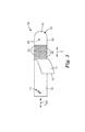
図1は、本明細書に開示される(ストライプ20及び40の長軸に沿って見た)例示的物品の一部の概略断面スライス図を示す。物品は、第1の主表面11と、第1の主表面11の反対側に面する第2の主表面12とを含む基材10を備える。第1の接着層5が基材10の第1の主表面11上に配設される。接着層5は、図1に例示的に示されているように、基材10の横方向の大きさ(lateral extent)「l」にわたってほぼ交互に並んだパターンで配置された、第1の感圧接着剤20の複数のストライプ及び第2の感圧接着剤40の複数のストライプを備える。(横方向、及び結果として得られる横方向の大きさとは、ストライプの長軸に対して実質的に垂直である方向を意味する。)第1の感圧接着剤20及び第2の感圧接着剤40は、本明細書において後で詳述するように、(例えば、組成が異なるという理由で)特性の異なる任意の2種類(又はそれ以上)の感圧接着剤であってもよい。基材10は、本明細書において詳述するように、所望の基材(例えば剥離ライナー)であってもよい。
FIG. 1 shows a schematic cross-sectional slice view of a portion of an exemplary article (as viewed along the long axes of
先に述べたように、感圧接着剤20及び40のストライプは、ほぼ交互に並んだパターンで配置される。このパターンの例示的な異形が、例えば図1〜3に示されており、図では[40/20/40/20...]のパターンが見られる。しかしながら、ほぼ交互に並んだという概念は、任意の選択されたストライプ(接着剤20又は40にかかわらず)を2つ以上のサブストライプの形態で提供することができるパターンも包含する。例えばストライプ20又は40の一方は、例えば、図1に示すような単一ストライプの代わりに、間に間隙を有する2つのサブストライプとして提供することができる。よって、例えば、ほぼ交互に並んだパターンは、[20/(40/40)/20/(40/40)...]のようなパターン、つまり、2つの40のサブストライプの後に単一の20のストライプが続くパターン、及び[(20/20)/(40/40/40)...]のようなパターン、つまり、2つの20のサブストライプの後に3つの40のサブストライプが続くパターンなどを包含する。多くの実施形態において、感圧接着剤20及び40のストライプは、長軸を含むように引っ張られるが(例えば、図3に示すように)、そのような長軸は必ずしも厳密に直線状である必要はない。
As mentioned above, the stripes of pressure
少なくともいくつかの実施形態では、開示される物品は、図2及び図3の例示的実施形態で示すように、第2の基材(例えば、テープ裏材)80を含んでもよい。そのような実施形態では、複数のストライプのうちの少なくとも選択されたストライプは、それぞれ、第1の基材10の剥離面11と接触する第1の主表面を含んでもよく、複数のストライプのうちの少なくとも選択されたストライプは、それぞれ、第2の基材80の第1の主面/表面81に感圧接着剤により接合される、第2の反対側に面する主表面を含むことができる。図2の例示の実施形態では、ストライプ20及び40は、基材10の表面11と接触する第1の主表面(それぞれ21及び41)を有し、また、ストライプ20及び40は、第2の基材80の第1の主面/表面81に接合される第2の主表面(それぞれ22及び42)を有する。しかしながら、本明細書における以降の考察から理解されるように、いつもこうとは限らない。
In at least some embodiments, the disclosed article may include a second substrate (eg, a tape backing) 80, as shown in the exemplary embodiments of FIGS. 2 and 3. In such an embodiment, at least selected stripes of the plurality of stripes may each include a first major surface in contact with the
第2の基材80は、例えば、任意の所望の種類の物品(例えばテープ)を形成するのに適している場合がある、任意の種類の裏材を含むことができる。特定の実施形態では、裏材80は、本明細書において後で詳述するような高伸張性裏材を含むことができ、それによって、得られる物品は、引き伸ばし剥離可能な接着テープとして機能することができる。いくつかの実施形態では、テープ裏材80の、第1の感圧接着剤層5の反対側となる第2の(反対)側に、第2の感圧接着剤層115が形成されてもよい。そのように配置することにより、いわゆる両面接着テープを得ることができる。所望の場合には、第2の接着層115は、第1の接着層5と同じ(例えば、ストライプ状の)配置及び/又は組成物を有してもよい。しかしながら、多くの実施形態では(接着層115は、多くの場合、壁自体の取り付け面ではなく、例えば壁に取り付けられるアイテムに接合される場合があるので)、第2の接着層115は任意の好適な接着剤を含むことができる。必要に応じて、図2の例示的実施形態に示すように、テープ裏材80の第2の側82に第2の剥離ライナー110が提供されてもよい。
The
いくつかの実施形態では、テープ裏材80、並びに第1の及び第2の接着層5及び115は、全体として、引き伸ばし剥離可能な両面接着テープを提供することができる。そのような物品は、多くの場合、例えば壁等のような建築部材にアイテムを取り外し可能に取り付けるために使用される。ひいては、図3は、例示的な引き伸ばし剥離可能な物品90を示しており、この物品90は高伸張性裏材80を含み、裏材80の一部には、第1及び第2の接着剤のストライプ20及び40が、ほぼ交互に並んだパターンで配置されている。物品90は、タブ部83(例えば、裏材80の、接着剤がその上に配置されていない部分)を更に含み、このタブ部83をつかんで引っ張ることにより、物品の引き伸ばし剥離特性を活性化させることができる。多くの実施形態では、そのような引き伸ばし剥離可能な物品は、長軸LSRを有する引張長さを含んでいてもよく、この長軸は、この軸に沿って物品を引っ張ることによって引き伸ばし剥離特性を活性化させることができる軸としての役割を果たす。図3から分かるように、いくつかの実施形態では、第1及び第2の接着剤の個々のストライプ20及び40は、それぞれ、引き伸ばし剥離可能な物品90の引張長さの長軸LSRに対して概ね、実質的に、又は更には厳密に垂直に配向された長軸を有することができる(後者の事例が図3に示されている)。そのような引き伸ばし剥離可能な物品は、通例、物品が支持するアイテムの重量を最も有利に支えるために、物品の長軸が(地球の引力に関して)鉛直に位置合わせされるように壁に取り付けられることが理解されるであろう。したがって、たとえ接着剤の個々のストライプが、物品の長軸に対して、したがって支持される物体によって加えられる重力負荷に対して、垂直に配向されている場合でも、本明細書に記述する機能が得られる場合がある点に留意されたい。しかしながら、種々の実施形態では、ストライプ20及び40の長軸は、引き伸ばし剥離可能な物品90の長軸LSRに対して任意の都合のよい角度で(例えば、平行に、又は平行から30、45、60、又は90度離れる角度で)配向されてもよい。また、上述のように、個々のストライプは、必ずしも完全な直線状に延びている必要はない。すなわち、ストライプは、少なくともわずかに波状、弓状、正弦曲線状等とすることができる。
In some embodiments, the tape backing 80 and the first and second
本明細書における後の開示に基づいて理解されるように、第1の接着層5は、有利にも、例えば建築部材の取り付け面、特にかかる部材の特定の塗面に対して、接合されてもよい。したがって、いくつかの実施形態では、第1の基材10の可視表面12は、第1の基材10が、建築部材の取り付け面に接合されるように構成された引き伸ばし剥離可能な両面接着テープ物品90の主面上に配設された剥離ライナーであることを(剥離ライナー10を除去する際に)示すしるし13を含んでもよい。そのような配置が図3の例示的実施形態に示されている。
As will be understood on the basis of the later disclosure herein, the first
接着層5の接着剤20及び40の個々のストライプは、任意の所望の(横方向の)幅を有してもよい。種々の実施形態では、個々のストライプは、少なくとも約0.1、0.2、又は0.4mmである平均幅を含んでもよい(ストライプの幅は、ストライプの長軸に沿って時々多少変化する場合があることに留意されたい)。更なる実施形態では、個々のストライプは、最大約2、1、又は約0.6mmの平均横幅を含む場合がある。特定の種類(例えば、接着剤20又は40)のストライプは、全てが同じ幅である必要はなく、更に、ストライプ20はストライプ40と同じ幅である必要はない。本明細書で述べるように、いくつかのストライプ20(及び40)の幅は、基材10に面する側と反対側とで幅が異なっている場合がある。そのようなストライプでは、平均幅は、ストライプのこれら2つの側の幅の平均を指す。
The individual stripes of
ストライプ20及び40は、任意の所望のピッチ(すなわち、隣接するストライプの中心間距離)で提供される場合がある。例えば、(例えば、従来型のテープを剥がすとき、又は引き伸ばし剥離可能なテープを伸張させるときに)比較的滑らかで連続的な除去プロセスを得ることができるように、ピッチは比較的小さい方が好都合である場合がある。したがって、種々の実施形態では、隣接するストライプの中心間ピッチは、最大約4、2.5、2、1.5、又は1mmとしてもよい。更なる実施形態では、そのような中心間ピッチは、少なくとも約0.5、1、1.5、又は2mmとしてもよい。ピッチは必ずしも一定である必要はないが、所望の場合には一定とすることができる。個々のストライプ20及び/又は40は、しばしば、それらの長軸に沿って連続している場合があるが、所望の場合には不連続(断続的)とすることができる。しかしながら、いずれの事例でも、かかるストライプは、例えばグラビアコーティング、スクリーン印刷等により点の配列として表面上に堆積された接着剤と区別される(すなわち、各ストライプは、それぞれがストライプの長軸と一致する長軸を含むセグメントから構成されているため)。
ストライプの厚さ
個々のストライプ20及び40は、(図1で指定したように、第1の基材10に対して内外方向の)任意の好適な平均厚さを有していてもよい。種々の実施形態では、ストライプ20及び/又は40は、少なくとも約10、20、40、又は60マイクロメートルの平均厚さを備える場合がある。更なる実施形態では、ストライプ20及び/又は40は、最大140、100、80、又は70マイクロメートルの平均厚さを備える場合がある。いくつかの実施形態では、特定の種類のストライプの厚さは全て類似していてもよく、及び/又はストライプ40は、ストライプ20とほぼ同じ平均厚さを有してもよい(図1、図2、図4、及び図5に示す一般的な設計において見られるように)。しかしながら、後で詳述するように、全てのストライプが同一の厚さ又は更には同様の厚さを有する必要はない場合がある。本明細書において後で述べるように、いくつかのストライプ20(及び/又は40)の厚さは、ストライプの横幅にわたって変動してもよい。そのようなストライプでは、平均厚さは、ストライプの横方向中央部において又はその近くで測定することができる(例えば、図6に示す厚さTlc)。いくつかの実施形態では、ストライプ20のライナーに面する主表面21は、ストライプ40のライナーに面する主表面41と面一であってもよい。
Stripe Thickness The
体積分率/厚さの不一致
本明細書に開示される配置は、第1の接着剤によって提供される実際の接合表面積を、接着層5に存在する第1の接着剤の体積分率に基づいて予想される接合表面積よりも大きくすることによって、利益をもたらすことができる。接着剤によって提供される体積分率とは、接着層5の総体積(存在する場合には間隙が占める体積を含む)に対して、接着剤のストライプが合計で占める割合(パーセンテージ)を意味する。少なくともいくつかの実施形態において、第1の接着剤20が存在する体積分率は、第1の接着剤20のストライプの少なくともいくつかの厚さが、第2の接着剤40のストライプの厚さと異なるように配置することによって操作することができる。具体的には、接着層5の許容可能な特性を維持しながら、より小さい体積分率の第1の接着剤20を使用するために、第2の接着剤40のストライプに対する第1の接着剤20のストライプの少なくともいくつかの厚さを、有利にも最小化してもよい(例えば図8の例示的設計に見られるように)。例として、実施例の表1〜3から、第1の接着剤ストライプ20の相対的(平均)厚さは、第2の接着剤ストライプ40の(平均)厚さよりも、例えば1.2.、1.5、2.0、2.5、3.0、又は更には3.4倍小さくもよいことが明らかである。そのような実施形態は、許容可能な接合を達成しかつ維持しながら、非常に低い体積分率の第1の接着剤20の使用を可能とすることができる。
Volume fraction / thickness mismatch The arrangement disclosed herein is based on the volume fraction of the first adhesive present in the
具体的な例として、実施例2−1(表2)は、約33%である第1の接着剤20の全体の面積分率を含んでいた(残部である67%は第2の接着剤40によって供給される)。しかしながら、第1の接着剤20のストライプは第2の接着剤40よりもかなり薄いので(約0.8ミル対2.7ミル(0.02ミリメートル対0.069ミリメートル))、第1の接着剤20の体積分率はたった約13%であった(残部である87%は第2の接着剤40からなる)。したがって、実施例2−1と比較例PSA−S−2の比較から、少なくともいくつかの実施形態では、100体積%の第1の接着剤20からなる接着層5の使用によって示される特性の少なくともいくつかを維持しながら、例えば約13%という低い体積分率の第1の接着剤20を含む接着層5を使用することができることが明らかである。
As a specific example, Example 2-1 (Table 2) included an overall area fraction of the first adhesive 20 that was about 33% (the remaining 67% was the second adhesive) 40)). However, since the stripe of the
したがって、種々の実施形態では、第2の感圧接着剤のストライプの平均厚さは、第1の感圧接着剤のストライプの平均厚さより、少なくとも1.2、1.6、2.0、2.5、3.0、又は3.5倍又はそれ以上大きくてもよい。(そのような実施形態では、ストライプ20のライナーに面する主表面21は、ストライプ40のライナーに面する主表面41と同一平面上であってもよい。)接着層5において第1の接着剤のストライプの厚さと第2の接着剤のストライプの厚さとの間に大きな不一致が存在すると(例えば、最大で3.4倍)、接着層5が接合を達成して維持する能力に悪影響を与えることが当業者によって予想され得る点に留意されたい。理論又は機序によって限定されることを望まないが、そのような厚さの不一致がある場合でも、いくつかの要因のいずれかによって、接着層5が適切な接合を達成して維持する能力を高めることができると考えられる。1つの要因は、ストライプの幅とストライプの厚さとのアスペクト比にある場合がある。アスペクト比を適切な範囲に設定することにより、より薄いストライプの「窪んだ」表面でさえも、そのほとんどを、接着層5を接合することが望まれる表面と接触させることができる。したがって、種々の実施形態では、本明細書に開示される接着剤ストライプのいずれかの幅/厚さアスペクト比は、少なくとも約5、10、20、又は40:1であってもよい。更なる実施形態では、そのようなアスペクト比は、最大約200、150、100、80、又は40:1であってもよい。
Thus, in various embodiments, the average thickness of the stripes of the second pressure sensitive adhesive is at least 1.2, 1.6, 2.0, more than the average thickness of the stripes of the first pressure sensitive adhesive. It may be 2.5, 3.0, or 3.5 times or more. (In such an embodiment, the
いくつかの実施形態で生じ得る別の要因は、(例えば引き伸ばし剥離可能な物品を形成するために)例えば高分子発泡体を含む比較的厚くかつ形状適合性を有する裏材である第2の基材80に、接着層5を接合することにある場合がある。図8の例示的な図に示すように、そのような裏材80は、厚さが一致しない接着剤ストライプ20及び40の輪郭に形状適合するのに十分な能力を示すことができるので、裏材80の表面81は、薄い方のストライプ20の窪んだ表面22にも接触して、接合を思い通りに達成しかつ維持することができる。したがって、種々の実施形態では、共形裏材80の厚さは、第1の接着層5の厚さの少なくとも約4、8、12、又は16倍であってもよい(厚さが一致しないストライプ20及び40が存在する場合には、そのような計算を行うために、より厚い方のストライプ(すなわち、ストライプ40)の厚さを第1の接着層5の厚さとして用いることに留意されたい)。
Another factor that may occur in some embodiments is a second group of relatively thick and conformable backings, including, for example, polymeric foam (eg, to form a stretch releasable article) There is a case in which the
更に別の要因は、剥離ライナーである基材10の表面上への接着剤ストライプの(例えば、本明細書において後で述べるようにコーティングによる)堆積である場合がある。これは、ストライプ20がストライプ40より薄い場合であっても、(剥離ライナー10を接着層5から分離した後に)取り付け面に接合される薄い方のストライプ20の接合表面21は、同様に取り付け面に接合される厚い方のストライプ40の接合表面41と概ね同一面である状態(同じ高さである状態)を維持することができるという有利な結果を有する。つまり、ストライプの厚さの不一致の影響は、主に(必要であれば、厚さの不一致を、例えば比較的厚くかつ形状適合性を有する裏材80で補償することができる)接着層5の反対側で顕著であり、例えば接着層5の、取り付け面に接合される表面においては、厚さ不一致の影響がほとんどないことが明白である。したがって、本明細書に開示される特徴のいくつかは、単独で又は組み合わされて、いくつかの状況において特に有利である場合がある。
Yet another factor may be the deposition (e.g., by a coating as described later herein) of the adhesive stripe onto the surface of the
接着剤を有しない間隙
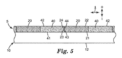
少なくともいくつかの実施形態では、上で開示した第1の接着剤20の体積分率の操作は、少なくとも部分的に、接着層5のストライプ(又はサブストライプ)の少なくともいくつかの間で、接着剤を有しない間隙を用いることによって達成される場合がある。そのような配置は、例えば図1〜図4に例示的な様式で示されている。したがって、そのような実施形態では、2つの隣接するストライプ20と40との間に間隙30が存在するように、ストライプ20及び40の少なくともいくつかは、基材10の横方向の大きさにわたって離間配置されていてもよく、この間隙30内に、図4に示すように、第1の基材10の第1の表面11の露出面11exが存在する。よって、第1の接着層5は、横方向に連続した(中断部のない)接着剤層を構成する必要がないことが理解されるであろう。すなわち、接着層5を、様々なストライプの間に散在している場合があるあらゆる間隙に関係なく、ストライプ20及び40によって集合的に提供することができる。図4に示す一般的なタイプの配置では、第1の接着剤ストライプ20の少なくともいくつかは、それぞれ、側方縁部の副表面(minor surface)24を含む側方縁部23を含む場合がある。同様に、少なくともいくつかの第2の接着剤ストライプ40は、それぞれ、側方縁部の副表面44を含む側方縁部43を含む場合がある。そのように「離間した」配置では、隣接するストライプ20及び40の縁部23及び43(具体的には、その表面24及び44)は、互いに接触しない。
Non-Adhesive Gaps In at least some embodiments, manipulation of the volume fraction of the first adhesive 20 disclosed above is at least partially at least some of the stripes (or sub-stripes) of the
具体的な例として、実施例1〜1(表1)では、第1の(シリコーン系)接着剤20の体積分率は約16%であり、第2の接着剤40の体積分率は約39%であり、様々なストライプの間の間隙の体積分率は約45%であった(これらの計算を行う方法についての考察は、試験手順を参照のこと)。主として高さの不一致を用いることによるか、少なくともいくつかの接着剤ストライプ間の間隙によるか、又はこれら両方のアプローチの組み合わせによるかにかかわらず、種々の実施形態において、第1の感圧接着剤20は、少なくとも約10、12、13、15、20、25、30、35、又は40%の体積分率で提供されてもよい。(接着層5の残部は、第2の接着剤40単独で、又は第2の接着剤40と接着剤を有しない間隙との組み合わせによって提供されてもよい。)更なる実施形態では、第1の接着剤20は、最大約55、50、45、40、35、30、25、又は20の体積分率で提供されてもよい。接着剤を有しない間隙が存在する場合には、有利にも間隙を間隙の面積分率として特徴付けることができる(以下更に詳細に述べる)。したがって、第1の接着剤20の本明細書に挙げる体積分率のいずれかを、例えば、約0、10、20、又は25%から、約60、50、40、又は35%までの間隙の面積分率と組み合わせて用いてもよい。
As a specific example, in Examples 1 to 1 (Table 1), the volume fraction of the first (silicone-based) adhesive 20 is about 16%, and the volume fraction of the
面積分率
例えば、少なくともいくつかのストライプの間に間隙が存在する一般的なタイプの設計を特徴付けるのを助けるために、第1及び第2の接着剤20及び40のそれぞれに関して、接着層5の総面積のうちの接着剤のストライプが合計で占める割合(パーセンテージ)である、全体の面積分率を規定することができる。全ての間隙によって集合的に提供される接着層5の間隙の面積分率は、同様に規定されてもよい。そうした面積分率の、例えば光学的方法による測定及び算出の詳細については、実施例の試験手順のセクションを参照されたい。ここで及び本明細書の他の箇所において、別途記載のない限り、面積分率は、接着層5の、第1の基材10とは反対側の表面についてのものである(多くの場合、例えば本明細書に記載する表面富化効果が存在しない場合、接着剤の第1の基材側の面積分率は、その接着剤の反対側の面積分率と本質的に等しいことに留意されたい。)
Area Fraction For example, with respect to each of the first and
具体的な例として、実施例1〜1(表1)の第1の接着剤の全体の面積分率は約23%、第2の接着剤の全体の面積分率は約33%、及び間隙の面積分率は約44%であった(これら3つのパラメータを加算すると接着層5の総面積である約100%となる)。したがって種々の実施形態において、第1の接着剤20は、接着層5の少なくとも約20、25、30、35、又は40%の全体の面積分率を提供してもよい。更なる実施形態では、第1の接着剤20は、接着層5の最大約70、60、50、又は40%の全体の面積分率を提供してもよい。
As a specific example, the total area fraction of the first adhesive of Examples 1 to 1 (Table 1) is about 23%, the total area fraction of the second adhesive is about 33%, and the gap The area fraction of is about 44% (adding these three parameters results in about 100% which is the total area of the adhesive layer 5). Thus, in various embodiments, the first adhesive 20 may provide an overall area fraction of at least about 20, 25, 30, 35, or 40% of the
実施例(例えば、表1)は、場合によっては、例えば最大で46%以上の間隙面積分率が存在する場合があることを示している。すなわち、場合によっては、接着層5の総面積の例えば46%以上もが、接着剤を欠く(つまり、基材10の露出面11exによって占められる)場合があるが、それでもなお(層5から剥離ライナー10が分離された後に接着層5がアイテムに接合されるとき)例えば剥離力及び剪断力に対して優れた抵抗を提供する。実際に、接着層の個々の接着剤ストライプが、それらの長軸が接着層にかかる剪断力(重力負荷)に対して垂直の状態で配向される(図3を参照して上述した)配置においても、優れた性能を維持することが可能である。接着剤ストライプの間の剪断経路に沿ったこのような大きな及び/又は多数の間隙の存在は、高剪断力に耐えるストライプの全体的能力を著しく低下させることが想定されたという点において、これは予想外である。よって、種々の実施形態では、接着層5は、少なくとも約10、20、30、又は40%の間隙面積分率を含む場合がある。更なる実施形態では、接着層5は、最大約60、50、45、40、35、又は30%の間隙面積分率を含む場合がある。(以下に記載するように、いくつかの実施形態では、間隙面積分率は10%未満であってもよく、特定の実施形態では、間隙が全く存在しなくてもよい。)
The examples (eg, Table 1) indicate that in some cases, a gap area fraction of, for example, up to 46% or more may be present. That is, in some cases, for example, as much as 46% or more of the total area of the
各接着剤に関して、接着剤のみの面積分率も規定することができ、このパラメータは、総面積に対して接着剤ストライプが占める割合を意味し、特定の接着剤のストライプによって提供される。したがって、接着剤のみの面積分率は、接着剤が存在しない間隙が占めるいかなる面積にも関係なく、第1及び第2の接着剤が占める相対面積を接着剤のみのベースで表す。例えば、実施例1〜2の第1の接着剤の接着剤のみの面積分率は約38%であり、実施例1〜2の第2の接着剤の接着剤のみの面積分率は約62%であった。 For each adhesive, the area fraction of the adhesive alone can also be defined, this parameter means the ratio of the adhesive stripe to the total area, provided by the particular adhesive stripe. Thus, the adhesive-only area fraction represents the relative area occupied by the first and second adhesives on an adhesive-only basis, regardless of the area occupied by the gap in the absence of the adhesive. For example, the area fraction of the adhesive only of the first adhesive of Examples 1-2 is about 38%, and the area fraction of the adhesive of the second adhesive of Examples 1-2 is about 62 %Met.
いくつかの状況では、本明細書に開示する、第1の接着剤20の比較的低い体積分率は、ストライプの厚さの不一致を用いることなく達成されてもよく、例えばいくつかの実施形態では、もっぱら接着剤を有しない間隙のみによって達成されてもよい。したがっていくつかの実施形態では、第1の接着剤ストライプ20の平均厚さは、第2の接着剤ストライプ40の平均厚さの±40、20、10、又は5%以内であってもよい。更に他の状況では、第1の接着剤ストライプ20の厚さは、第2の接着剤ストライプ40の厚さよりも大きいのが望ましい場合がある。
In some circumstances, the relatively low volume fraction of the first adhesive 20 disclosed herein may be achieved without using a stripe thickness mismatch, eg, some embodiments Here, it may be achieved solely by the gap without adhesive. Thus, in some embodiments, the average thickness of the first
互いに側面接触するストライプ
いくつかの実施形態では、第1の接着剤20及び第2の接着剤40の隣接するストライプの少なくとも選択された複数の対は、第1の感圧接着剤ストライプ20の側方縁部23の副表面24が、第2の感圧接着剤ストライプ40の側方縁部43の副表面44と、概ね側面接触するように構成される場合がある。そのような配置が図5に例示的に示されている。概ね側面接触しているとは、表面24と44との間の境界面の大部分が、基材10の主面に対して概ね垂直に(すなわち垂直±20度の範囲内で)整列されていることを意味することが理解されるであろう。そのような配置は、例えば、本明細書において後述する、図6に示すもののような配置と区別される場合がある。したがって、いくつかの実施形態では、本明細書に開示する、第1の接着剤が存在する体積分率の低減は、接着剤を有しない間隙を用いることなく達成される場合がある。例えばいくつかの実施形態では、この低減は、もっぱらストライプ40よりも薄いストライプ20を用いることによってのみ達成されてもよい。
Stripes Side-Contacting to Each Other In some embodiments, at least selected pairs of adjacent stripes of the
表面が富化されたストライプ
いくつかの実施形態では、第1の接着剤20及び第2の接着剤40の隣接するストライプの少なくとも選択された複数の対は、第1の感圧接着剤ストライプ20側方縁部部分25(幅wle)が、第2の感圧接着剤ストライプ40の側方縁部部分45の下内方に横たわるように(図6の例示的実施形態に示すように)構成されてもよい。(この一般的なタイプの多くのストライプは、例えば図6に示すように、幅Wlcを有する横方向中央部分26の側面に位置するこのような側方縁部部分25を2つ含むことになる。)図6の例示的な図から理解されるように、下内方に横たわるとは、第2の接着剤ストライプ40の部分45を通して外から中に向かう方向に通過する直線が、基材10に到達する前に第1の接着剤ストライプ20の部分25を通過することを意味する。したがってそのような配置では、ストライプ20及び40の隣接する縁部表面の間の境界面48は(図5の設計のように)基材80の主面に対して実質的に垂直ではなく、むしろ(隣接する縁部表面28及び47の間の)境界面48は、例えば、図6に示すように垂直とはかけ離れた角度で延びていてもよい。更に、同様に図6の例示的実施形態に示すように、境界面48の角度は、必ずしも一定である必要はない。(いくつかのそのような実施形態では、境界面48の角度は、ストライプ20の表面21に近付くにつれて減少してもよく、それにより部分25は、例えば、図6に示すような横方向に細長いフランジ部を含んでもよい。)
Surface-Enriched Stripes In some embodiments, at least a selected plurality of adjacent stripes of the
そのような設計によって大きな利益を付与することができる。具体的には、一部の特定用途では、基材ライナー10の表面11に、第2の接着剤40が存在する代わりに、高性能の第1の接着剤20を、(側方縁部部分25内の比較的薄い表面層内に)かかる位置と接して優先的に提供することが可能となる。すなわち、第1の接着剤20の、基材10の表面11と接している第1の表面21の面積は、接着層5内の第1及び第2の接着剤の総量に基づいて予想されるよりも大きい場合がある。この配置は、本明細書において、第1の接着剤20の表面富化と呼ばれる。接着層5から基材10を分離したとき、その結果露出される第1の接着剤20の表面21は、例えば建築部材の表面の、接着剤で接合されるべき適切な位置にあることが理解されるであろう。よって、この表面における第1の接着剤20の富化は、接着層5で使用される第1の接着剤20の量を全体的に最小限に抑えながら、特定の表面に対する強化接合をもたらすことができる。そのような表面富化配置は、有利にも本明細書に開示される他の配置と組み合わせて使用されてもよい。本明細書の実施例で実証されるように、表面富化は、例えば、接着層5の第1の基材側の第1の接着剤20の面積分率、及び接着層5の反対側の第1の接着剤20の面積分率を得て、これらを比較することによって、好都合に特徴付けることができる。
Such a design can provide significant benefits. Specifically, in some specific applications, instead of the presence of the second adhesive 40 on the
いくつかの実施形態では、図6に示されている一般配置を、極端な形で利用してもよい。すなわち、図7に例示的な様式で示すように、第2の接着剤ストライプ40の横方向側面に位置する2つの第1のストライプ20及び20’の側方縁部部分25及び25’は、それらが接触して第2のストライプ40の下に完全に横たわるまで、互いに向かって横方向に延びてもよい。すなわち、そのような場合には、基材10の表面11と接触する接着層5の接着表面積の本質的に100%が、第1の接着剤20によって提供されてもよい。表面富化配置は、本出願と同日に出願された係属中の米国特許出願第61/838,533号、代理人整理番号第74306US002号、発明の名称「Pressure-Sensitive Adhesive Layers with Surface-Enriched Stripes andMethods of Making」に詳細に論じられており、その全体は参照により本明細書に組み込まれる。
In some embodiments, the general arrangement shown in FIG. 6 may be utilized in an extreme manner. That is, as shown in an exemplary manner in FIG. 7, the
高湿/静的剪断での建築塗料への接合
当業者は、接着層の全体的性能に対する接着層内の2つの異なる接着剤の寄与は、各接着剤が存在する接合領域に概ね比例することになると予測することができることに留意されたい。対称的に、本発明の研究では、本明細書に開示される第1の接着剤の少なくともいくつかの有利な効果は、第1の接着剤が提供する接合領域の割合と比例しないことが見出された。
Bonding to Architectural Coatings at High Humidity / Static Shear One of ordinary skill in the art will appreciate that the contribution of the two different adhesives in the adhesive layer to the overall performance of the adhesive layer is roughly proportional to the joint area where each adhesive is present It should be noted that it can be predicted. In contrast, studies of the present invention show that at least some of the advantageous effects of the first adhesive disclosed herein are not proportional to the proportion of bonding area provided by the first adhesive. It was issued.
具体的詳細では、本発明者らは、少なくともある種の接着剤(例えばシリコーン系接着剤)は、たとえ高湿に曝されたとしても、また、たとえ接着層が、例えば極性部分を含む(例えば、表面に存在する場合がある親水性添加剤等による)ある種の表面に接合されるとしても、剪断力に対する接着層5の抵抗を長期間にわたって有利に維持することができることを見出した。特に、業界ではしばしば建築塗料と呼ばれるある種の塗料は、例えばそのような極性部分を含む場合がある(極性部分は、例えば種々の界面活性剤、添加剤等に存在する場合があり、塗料の汚れ除去性(洗浄性)を向上させるのを助けることができる)。この説明のために、建築塗料とは、次の基準を満たす塗料を意味する:ASTM D4828−94に概説されている手順に概ね従って試験した場合に、塗料は、少なくとも5(中度)、7(広範囲)、又は10(全ての汚れが除去された)の汚れ除去評価点を示し、かつ代表的な有機高分子感圧接着剤層を塗料に接合し、本明細書の実施例に概説されている手順に従って高湿/静的剪断試験に曝した場合に、接着層は10000分未満の破損時間を示す。(そのような試験を実施する目的で、本明細書に比較例PSA−O−1として記載される接着剤を、代表的な有機高分子接着剤として使用してもよい。)
In a specific detail, we note that at least some adhesives (eg silicone adhesives), even if exposed to high humidity, even if the adhesive layer comprises eg polar parts (eg It has been found that the resistance of the
この説明の参照基準として、例示的な有機高分子感圧接着剤は、例示的な建築塗料に接合されて高湿条件下で保持された場合、高剪断荷重に、例えば約2500分しか耐えることができずに落下する(本明細書の比較例PSA−O−1−Aに記載されている通り)。代表的なシリコーン系感圧接着剤は、これらの同一条件下で少なくとも約30000分の閾値レベル(これは当該分野で許容可能な性能を表すことが見出されている)を達成することができる(本明細書の比較例PSA−S−2−Aに記載されている通り)。当該技術分野の背景知識に基づいて、当業者は、接合表面がこれら2つの接着剤を50/50の比率で含む接着層は、2つの個々の接着剤の挙動の間の比例的な挙動を示すことになると予想する場合がある。しかしながら、本明細書の実施例で実証された通り、シリコーン接着剤の全体的な接合面積の割合は、例えば23%と低くても、高湿/静的剪断試験において少なくとも約30000分という望ましい閾値性能レベルを達成することができる。例として、接着層5の、建築塗料に接合された接合表面が、約23面積%の第1のシリコーン系接着剤と、約33面積%の第2の有機高分子接着剤と、約44%の間隙面積分率を含んだ実施例1−1(表1)は、上述した閾値要件を満たした(すなわち、この点において、比較例PSA−S−2−Aの100%シリコーン系接着剤の性能に匹敵するように見られた)。
As a reference for this description, the exemplary organic polymeric pressure sensitive adhesive should withstand high shear loads, for example, only about 2500 minutes when bonded to the exemplary architectural paint and held under high humidity conditions. Can not be dropped (as described in Comparative Example PSA-O-1-A herein). Representative silicone-based pressure sensitive adhesives can achieve threshold levels of at least about 30,000 minutes under these same conditions, which are found to exhibit acceptable performance in the art. (As described in Comparative Example PSA-S-2-A herein). Based on the background knowledge in the art, those skilled in the art will note that adhesive layers in which the bonding surface contains these two adhesives in a ratio of 50/50 give proportional behavior between the behavior of the two individual adhesives. You may expect to be shown. However, as demonstrated in the examples herein, the percentage of silicone bond overall bonding area is as low as 23%, for example, a desirable threshold of at least about 30000 minutes in a wet / static shear test. Performance levels can be achieved. As an example, the bonding surface of the
幅広い概要では、本明細書に開示されたいくつかの配置のいずれかを個別に又は任意の組み合わせで用いることによって、第1の接着剤(例えば所与の用途に対して優れた特性を有する接着剤)の有意な体積分率及び/又は面積分率を、十分な性能閾値を満たしながら、例えば性能の低い接着剤で置き換えてもよく、及び/又は接着剤が全く存在しない間隙で置き換えてもよい。すなわち、本発明者らは、本明細書に開示される配置が、第1の高性能の接着剤が接着層5に存在するレベルと比例していない性能を提供する可能性があることを実証した。これらの発見により、第1の接着剤を100%体積分率で含有する接着層で達成されることになる特性を有意に、又は更には実質的に維持しながら、かかる第1の接着剤の体積分率を大幅に省くことが可能となる。
In a broad overview, a first adhesive (eg, an adhesive having superior properties for a given application) by using any of the several arrangements disclosed herein, individually or in any combination. Agent) may be replaced by, for example, a low performance adhesive while meeting sufficient performance thresholds, and / or even by gaps where no adhesive is present Good. That is, the inventors demonstrate that the arrangement disclosed herein may provide performance that is not proportional to the level at which the first high performance adhesive is present in the
ここでも同様に、そのような結果は、例えば、(例えば実施例2−1のように)2つの接着剤のストライプの間に厚さ不一致をもたらすことによって、第1の接着剤の有意な体積分率を第2の接着剤で置き換えることによって、及び/又は、(例えば実施例1〜1のように)第1の接着剤の有意な体積分率を、第2の接着剤と接着剤を有しない間隙との組み合わせで置き換えることによって得られる場合があることが理解されるであろう。このようにして、いずれかのアプローチにより、第1の接着層5の体積分率を、許容可能な特性を維持しながら、所望に応じて例えば10〜20%にまで減少させることができる。本明細書に記載される表面富化効果は、そのような効果を増大させる及び/又は増幅させることができることが更に理解されるであろう。
Again, such a result is a significant volume of the first adhesive, for example by providing a thickness mismatch between the two adhesive stripes (as in Example 2-1). By replacing the fraction with a second adhesive and / or a significant volume fraction of the first adhesive (for example as in Examples 1 to 1), the second adhesive and the adhesive It will be appreciated that it may be obtained by replacement in combination with a gap that does not have. In this way, either approach can reduce the volume fraction of the first
本明細書に開示される配置は、任意の状況及び用途において利点を提供できる。例として、第1の接着剤がシリコーン系接着剤である実施例が本明細書に提示されており、このシリコーン系接着剤は、例えば高湿度の存在下であっても、いわゆる建築塗料に対する接着接合を維持するための高い能力を付与することが示されている。これらの結果は、本明細書に記載する高湿/静的剪断試験によって実証されている。しかしながら、選択された特定の接着剤、及び行われた特定の試験は、例示的な特性のものであることが強調される。任意の所望の結果を得るために、第1の接着剤が(本明細書に開示される任意の配置の単独によって、又は任意の組み合わせによって)表面富化されている、特性の異なる任意の第1及び第2の接着剤を、任意の好適な目的のために使用してもよい。 The arrangements disclosed herein can provide advantages in any situation and application. By way of example, an example is presented herein in which the first adhesive is a silicone-based adhesive, this silicone-based adhesive, for example, adheres to so-called architectural coatings even in the presence of high humidity. It has been shown to impart a high ability to maintain the bond. These results are demonstrated by the high humidity / static shear test described herein. However, it is emphasized that the particular adhesive chosen and the particular test performed is of exemplary nature. Any of the different properties of the first adhesive being surface enriched (by any of the arrangements disclosed herein alone or in any combination) to achieve any desired result. One and a second adhesive may be used for any suitable purpose.
感圧接着剤
第1の接着剤20及び第2の接着剤40は共に、感圧接着剤である。(2接着剤系(two-adhesive system)の最も簡単な例が本明細書で論じられているが、所望する場合には、第3、第4、又は更にはそれ以上の接着剤が存在してもよいことが理解されるであろう。)唯一の要件は、第1及び第2の接着剤が、互いに異なる1つの特性(具体的には、幅及び厚さなどの示量性特性(例えば、幾何学的特性)ではなく、ある種の、例えば示強性)を有することである。第1の接着剤と第2の接着剤とで異なっていてもよい特性は、融点、ガラス転移温度、弾性係数、剥離強度、剪断強度、硬度、透湿性、撥水性、吸油量、水及び/又は有機溶媒への可溶性、耐温度性、紫外線抵抗性などのうちの1つ又は2つ以上であってもよい(しかし、限定するものではない)。そのような特性の違いは、例えば組成の違いによって達成される場合があるが、非常に類似した組成の接着剤でさえも、例えば異なる加工履歴を受けることによって、異なる特性を示す場合があることが理解されるであろう。すなわち、第1及び第2の接着剤は(組成が同様であるかそうでないかにかかわらず)、例えば結晶化度パーセント、自由体積、架橋密度などが異なってもよい。いくつかの実施形態では、第1及び第2の接着剤20及び40の一方又は両方は、再付着性接着剤であってもよい。代替実施形態では、第1及び第2の接着剤20及び40はいずれも再付着性でない。
Pressure-Sensitive Adhesives The
感圧接着剤は、通常、室温で粘着性であり、ただ軽い指圧のみを加えることによって表面に接着することができ、したがって感圧性でない他のタイプの接着剤と区別される場合がある。感圧接着剤の一般的な説明は、「Encyclopedia of Polymer Science and Engineering」(Vol.13,Wiley-Interscience Publishers(New York,1988))に見出すことができる。感圧接着剤の更なる説明は、「Encyclopedia of Polymer Science and Technology」(Vol.1,Interscience Publishers(New York,1964))に見出すことができる。少なくともいくつかの実施形態では、感圧接着剤は、Handbook of Pressure-Sensitive Adhesive Technology,D.Satas,2nded.,page 172(1989)に記載のダルキスト基準を満たすことができる。この基準は、感圧接着剤を、使用温度において(例えば、15℃〜35℃の範囲内の温度において)1×10⁻⁶cm2/ダインを超える1秒クリープコンプライアンスを有するものとして定義する。 Pressure sensitive adhesives are usually tacky at room temperature and can be adhered to surfaces only by applying light finger pressure, and thus may be distinguished from other types of adhesives that are not pressure sensitive. A general description of pressure sensitive adhesives can be found in "Encyclopedia of Polymer Science and Engineering" (Vol. 13, Wiley-Interscience Publishers (New York, 1988)). A further description of pressure sensitive adhesives can be found in "Encyclopedia of Polymer Science and Technology" (Vol. 1, Interscience Publishers (New York, 1964)). In at least some embodiments, the pressure sensitive adhesive can meet the dulquist criteria described in Handbook of Pressure-Sensitive Adhesive Technology, D. Satas, 2 nd ed., Page 172 (1989). This criterion defines a pressure sensitive adhesive as having a one second creep compliance of greater than 1 × 10 −6 cm 2 / dyne at service temperature (eg, at a temperature in the range of 15 ° C. to 35 ° C.).
任意の好適な組成及び任意の好適な特性を有する任意の好適な感圧接着剤を、第1及び第2の感圧接着剤20及び40の一方又は両方で使用することができる。いくつかの実施形態では、第1及び第2の接着剤20又は40の少なくとも一方は、シリコーン系感圧接着剤である。いくつかの実施形態では、第1の接着剤20は、第1の一連の特性を有する第1のシリコーン系接着剤であり、第2の接着剤40は、(第1の接着剤と組成物が異なっていてもよい)第2の一連の特性を有する第2のシリコーン系接着剤である。そのような接着剤は、典型的には、少なくとも1つのシリコーンエラストマーポリマーを含み、かつ粘着付与樹脂などの他の任意選択的な成分を含んでもよい。シリコーンエラストマーポリマーは、それぞれが少なくとも1つの極性部分を含むハードセグメントを含むシリコーンブロックコポリマーエラストマーであってもよい。極性部分とは、尿素結合、オキサミド結合、アミド結合、ウレタン結合、又はウレタン−尿素結合を意味する。したがって、好適なシリコーンブロックコポリマーエラストマーとしては、例えば、尿素系シリコーンコポリマー、オキサミド系シリコーンコポリマー、アミド系シリコーンコポリマー、ウレタン系シリコーンコポリマー、及びこれらの混合物が挙げられる。そのようなシリコーン系感圧接着剤は、本出願と同日に出願された係属中の米国特許出願第61/838,504号、代理人整理番号第71412US002号、発明の名称「Article Comprising Pressure-Sensitive Adhesive Stripes」に詳細に記載されており、その全体は参照により本明細書に組み込まれる。他のシリコーン系接着剤は、当業者に良く知られている、例えば、熱硬化性のもの(例えば、白金硬化性、過酸化物硬化性、水分硬化性シリコーンポリマーなど)に基くものであってもよい。そのようなシリコーンは、必ずしも上記ハードセグメントを含んでいなくてもよい。
Any suitable pressure sensitive adhesive having any suitable composition and any suitable properties may be used in one or both of the first and second pressure
シリコーン系感圧接着剤組成物(例えばハードセグメンを有するブロックコポリマーに依存するか、又は任意の他の種類のシリコーンエラストマーに依存するかにかかわらない)は、しばしば、MQ粘着付与樹脂を含む場合がある。上記の種類及び変形形態のいずれかのシリコーン系接着剤は、形成されてストライプ20及び/又は40となるような任意の好適な形態で提供される場合がある。例えば、そのような接着剤は、流動性のある液体である前駆体液の形態で提供されてもよく、この前駆体液は、基材10上に堆積されて前駆体液のストライプを形成することができ、この前駆体は、次に、最終形態であるシリコーン系接着剤へと変換することができる。よって、流動性のある前駆体液は、本明細書において後で述べるように、例えばホットメルトコーティンに適した、例えば100%固形分の混合物、若しくは水性エマルション(例えばラテックス)、又は1種若しくは2種以上の好適な溶媒中の溶液であってもよい。
Silicone based pressure sensitive adhesive compositions (for example depending on block copolymers with hard segments or not on any other type of silicone elastomer) often contain an MQ tackifying resin is there. The silicone-based adhesive of any of the above types and variations may be provided in any suitable form so as to be formed into
いくつかの実施形態では、第1及び第2の接着剤20又は40の少なくとも一方は、有機高分子感圧接着剤である。いくつかの実施形態では、第1の接着剤20は、第1の一連の特性を有する第1の有機高分子接着剤であり、第2の接着剤40は、(第1の接着剤の組成物と異なっていてもよい)第2の一連の特性を有する第2の有機高分子接着剤である。有機高分子感圧接着剤は、定義によれば、10重量パーセント未満(乾燥重量基準)のシリコーン系感圧接着剤を含む。種々の実施形態では、かかる接着剤は、4、2又は1%未満のシリコーン系接着剤を含んでもよい。多くの実施形態では、かかる接着剤は、シリコーン系感圧接着剤を実質的に含有しない(すなわち0.2重量パーセント未満)。しかしながら、いくつかの状況では、かかる接着剤は、何らかの少量の(例えば、2.0、1.0、0.4、0.2、0.1、又は0.05重量パーセント未満の)シリコーン含有添加剤(例えば、乳化剤、可塑剤、安定剤、湿潤剤等)を含んでもよいことが理解されるであろう。接着剤に感圧特性を付与する以外の何らかの目的で1つ以上のシリコーン含有添加剤が存在するような状況は、そのような接着剤がシリコーン系接着剤であると見なされる状況を生じる可能性はない。
In some embodiments, at least one of the first and
有機高分子感圧接着剤とは、接着剤が、少なくとも1つの有機高分子エラストマー(任意選択的に、1つ又は2つ以上の粘着付与樹脂などの他の構成成分との組み合わせ)に基いていることを意味する。有機高分子接着剤は、純粋な炭化水素である有機高分子エラストマーに基いている必要はない(しかしながら所望の場合にはそうであってもよい)ことが理解されるであろう。むしろ、上で概説した基準に従って特定のヘテロ原子Siの存在が最小限にされる限りにおいて、ヘテロ原子(例えばO、N、Clなど)が存在することは許容される(エラストマー鎖の主鎖内であるか、及び/又はその側鎖内であるかにかかわらず)。 An organic polymeric pressure sensitive adhesive is one in which the adhesive is based on at least one organic polymeric elastomer (optionally in combination with other components such as one or more tackifying resins) Means to It will be appreciated that the organic polymeric adhesive need not be based on organic polymeric elastomers that are pure hydrocarbons (although it may be so if desired). Rather, it is acceptable for the presence of heteroatoms (eg O, N, Cl etc.) (within the main chain of the elastomer chain) as long as the presence of the particular heteroatom Si is minimized according to the criteria outlined above. And / or within its side chain).
有機高分子感圧接着剤で使用するのに好適である場合がある例示的材料の一般的なカテゴリーとしては、例えば天然ゴムベースのエラストマーポリマー;合成ゴム(例えば、ブチルゴム、ニトリルゴム、多硫化ゴム);ブロックコポリマー;アクリレート及び/又はメタクリレート材料等の反応生成物が挙げられる。(本明細書において使用する場合、(メタ)アクリレート、メタ(アクリル)などの用語は、アクリル/アクリレートの両方、及びメタクリル/メタクリレート、モノマー、オリゴマー、及びこれらから誘導されるポリマーを指す)。そのような接着剤のそのようなエラストマーポリマーに含めるのに適した特定のポリマー及び/又はコポリマー及び/又はモノマー単位としては、ポリビニルエーテル、ポリイソプレン、ブチルゴム、ポリイソブチレン、ポリクロロプレン、ブタジエンアクリロニトリルポリマー、スチレン−イソプレン、スチレン−ブチレン、及びスチレン−イソプレン−スチレンブロックコポリマー、エチレン−プロピレン−ジエンポリマー、スチレン−ブタジエンポリマー、スチレンポリマー、ポリアルファオレフィン、非晶質ポリオレフィン、エチレン酢酸ビニル、ポリウレタン、シリコーン尿素ポリマー、ポリビニルピロリドン、並びこれらの任意の組み合わせ(ブレンド、コポリマー等)を挙げてもよいが、これらに限定されない。好適な(メタ)アクリル材料の例としては、例えば、メチルメタクリレート、エチルメタクリレート、n−ブチルメタクリレート、メチルアクリレート、エチルアクリレート、n−ブチルアクリレート、イソオクチルアクリレート、イソノニルアクリレート、2−エチル−ヘキシルアクリレート、デシルアクリレート、ドデシルアクリレート、n−ブチルアクリレート、ヘキシルアクリレート、オクタデシルアクリレート、オクタデシルメタクリレート、アクリル酸、メタクリル酸、アクリロニトリル、及びこれらの組み合わせなどのアルキルアクリレート又はメタクリレートモノマーのポリマーが挙げられる。好適な市販のブロックコポリマーの例としては、商品名「KRATON」でKraton Polymers(Houston,TX)から入手可能なものが挙げられる。これらの、又は他の好適な材料のいずれかが、任意の所望の組み合わせで使用されてもよい。いくつかの有用な有機高分子感圧接着剤の一般的な説明は、「Encyclopedia of Polymer Science and Engineering」(Vol.13,Wiley-Interscience Publishers(New York,1988))に見出すことができる。いくつかの有用な有機高分子感圧接着剤の更なる説明は、「Encyclopedia of Polymer Science and Technology」(Vol.1,Interscience Publishers(New York,1964))に見出すことができる。 General categories of exemplary materials that may be suitable for use in organic polymeric pressure sensitive adhesives include, for example, natural rubber based elastomeric polymers; synthetic rubbers (eg butyl rubber, nitrile rubber, polysulfide rubber) Block copolymers; reaction products such as acrylate and / or methacrylate materials. (As used herein, the terms (meth) acrylate, meta (acrylic), etc. refer to both acrylic / acrylate, and methacrylic / methacrylate, monomers, oligomers, and polymers derived therefrom). Specific polymers and / or copolymers and / or monomer units suitable for inclusion in such elastomeric polymers of such adhesives, such as polyvinyl ethers, polyisoprenes, butyl rubbers, polyisobutylenes, polychloroprenes, butadiene acrylonitrile polymers, Styrene-isoprene, styrene-butylene and styrene-isoprene-styrene block copolymers, ethylene-propylene-diene polymers, styrene-butadiene polymers, styrene polymers, polyalphaolefins, amorphous polyolefins, ethylene vinyl acetate, polyurethanes, silicone urea polymers Polyvinyl pyrrolidone, and any combination thereof (blends, copolymers, etc.) may be mentioned, but is not limited thereto. Examples of suitable (meth) acrylic materials are, for example, methyl methacrylate, ethyl methacrylate, n-butyl methacrylate, methyl acrylate, ethyl acrylate, n-butyl acrylate, isooctyl acrylate, isononyl acrylate, 2-ethyl-hexyl acrylate And polymers of alkyl acrylate or methacrylate monomers such as decyl acrylate, dodecyl acrylate, n-butyl acrylate, hexyl acrylate, octadecyl acrylate, octadecyl methacrylate, acrylic acid, methacrylic acid, acrylonitrile, and combinations thereof. Examples of suitable commercially available block copolymers include those available from Kraton Polymers (Houston, Tex.) Under the tradename "KRATON". Any of these or other suitable materials may be used in any desired combination. A general description of some useful organic polymeric pressure sensitive adhesives can be found in "Encyclopedia of Polymer Science and Engineering" (Vol. 13, Wiley-Interscience Publishers (New York, 1988)). Further description of some useful organic polymeric pressure sensitive adhesives can be found in "Encyclopedia of Polymer Science and Technology" (Vol. 1, Interscience Publishers (New York, 1964)).
必要に応じて、有機高分子接着剤に粘着付与樹脂が含まれる場合がある。(当業者は、いくつかのエラストマーは自己粘着性である場合があり、したがって粘着付与樹脂を付加する必要がほとんど又は全くない場合があることを更に理解するであろう。)任意の好適な粘着付与樹脂、又はこれらの組み合わせが使用されてもよい。好適な粘着付与樹脂としては、例えば、ウッドロジン、及びその水素添加誘導体、トール油ロジン、テルペン樹脂、フェノール樹脂、ポリ芳香族化合物、石油系樹脂(例えば、脂肪族C5オレフィン誘導樹脂)などが挙げられる。加えて、感圧接着剤40は、可塑剤、充填剤、抗酸化剤、安定剤、顔料などの添加剤を含むことができる。 As needed, the organic polymer adhesive may contain a tackifying resin. (One of ordinary skill in the art will further appreciate that some elastomers may be self-tacky, and thus may require little or no tackifying resin addition.) Any suitable tackiness Application resins, or combinations thereof may be used. Suitable tackifying resins include, for example, wood rosin and hydrogenated derivatives thereof, tall oil rosin, terpene resin, phenolic resin, polyaromatic compound, petroleum resin (for example, aliphatic C5 olefin derivative resin), etc. . In addition, pressure sensitive adhesive 40 can include additives such as plasticizers, fillers, antioxidants, stabilizers, pigments and the like.
表面に対して良好な接着をもたらす一方でまた、例えば目に見える残滓などの残留物を残すことなく、適度な力で除去可能であるので、有機感圧接着剤の構成要素を、選択することが便利である場合がある(例えば、マスキング及び/又は引き伸ばし剥離用途のため)。ある実施形態では、感圧接着剤は、天然ゴム系である場合があり、これは、天然ゴムエラストマー(複数可)が、接着剤のエラストマー成分の少なくとも約70重量%を構成することを意味する(充填剤、粘着付与剤などを含まない)。いくつかの実施形態では、有機高分子エラストマーは、炭化水素ブロックコポリマーエラストマー(例えば、Kraton Polymers(Houston,TX)から商標名KRATONで入手可能な一般的種類)であってもよい。具体的な実施形態では、ブロックコポリマーエラストマーは、例えば、スチレン−ブタジエン−スチレン(SBS)又はスチレン−イソプレン−スチレン(SIS)ブロックコポリマー、これら2つのブレンド、これらの両方のうちのいずれかと天然ゴムエラストマーとのブレンドなどであってもよい(例えば少なくとも1つの粘着付与樹脂と併用する)。 Choosing an organic pressure sensitive adhesive component, as it provides good adhesion to the surface while also being removable with moderate force without leaving residue such as visible debris May be convenient (eg, for masking and / or stretch release applications). In some embodiments, the pressure sensitive adhesive may be natural rubber based, which means that the natural rubber elastomer (s) constitute at least about 70% by weight of the elastomeric component of the adhesive. (Does not contain fillers, tackifiers, etc.). In some embodiments, the organic polymeric elastomer may be a hydrocarbon block copolymer elastomer (eg, a general type available under the tradename KRATON from Kraton Polymers (Houston, Tex.)). In a specific embodiment, the block copolymer elastomer is, for example, styrene-butadiene-styrene (SBS) or styrene-isoprene-styrene (SIS) block copolymer, a blend of the two, either of these, and a natural rubber elastomer And the like (eg, in combination with at least one tackifying resin).
上記の種類及び変形形態のいずれかの有機高分子接着剤は、形成されてストライプ20及び/又は40となるような任意の好適な形態で提供されてもよい。例えば、そのような接着剤は、流動性のある液体である前駆体液の形態で提供されてもよく、該前駆体液は、基材10上に堆積されて前駆体液のストライプを形成することができ、この前駆体を、次に、最終形態である有機高分子接着剤へと変換することができる。よって、流動性のある前駆体液は、本明細書において後で述べるように、例えばホットメルトコーティンに適した、例えば100%固形分の混合物、若しくは水性エマルション(例えばラテックス)、又は1種以上の好適な溶媒中の溶液であってもよい。
The organic polymeric adhesive of any of the above types and variations may be provided in any suitable form so as to be formed into
第1の基材
第1の基材10は、一時的又は恒久的にかかわらずその上に接着層5を堆積させる(例えば、コーティングによって)のが望ましい、任意の好適な基材とすることができる。多くの実施形態では、基材10は剥離ライナーである。そのような剥離ライナー10は、第1の主表面11上に剥離面を備え、この剥離面は、剥離ライナー10から感圧接着剤を剥離するのに適している。剥離ライナー10は、任意選択的に、第2の主表面12上に剥離面を含んでいてもよい。特定の実施形態では、第2の主表面12上の剥離面は、第1の主表面11の剥離特性と同一の又は異なる剥離特性を含んでもよい(したがって、当業者であれば十分理解するであろうように、後者の場合、ライナー10は、いわゆる示差剥離ライナーである)。
First Substrate The
剥離面11(及び、存在する場合には、剥離面12)は、任意の好適な材料によって(又は、剥離ライナー10を作製する材料の表面の任意の好適な処理によって)提供することができる。接着層5が、例えば、有機高分子接着剤を含み、シリコーン系接着剤をほとんど又は全く有しない場合には、かかる剥離面は、例えば、任意の好適なコーティング(例えばワックス等)であってもよい。あるいは、任意の好適な高分子量のポリマーの層(例えば、コーティング)(例えば、ポリエチレン等のようなポリオレフィンの層)を使用してもよい。多くの層及び処理がそうした用途に適していることが理解されるであろう。
The release surface 11 (and, if present, the release surface 12) can be provided by any suitable material (or by any suitable treatment of the surface of the material from which the
接着層5が相当量のシリコーン系接着剤を含む場合には、シリコーン系接着剤を剥離面11から剥離する能力を増強する組成物で剥離面11を提供するのが有利である場合がある。フッ化物材料がそのような目的のためにしばしば使用される。潜在的に好適な材料の例としては、例えばフルオロケミカル、フルオロカーボン、フルオロシリコーン、ペルフルオロポリエーテル、ペルフルオロポリウレタンなどのフッ化物材料、及びそれらの組み合わせが挙げられるが、これらに限定されない。特定の実施形態では、フッ素化された剥離面は、フルオロシリコーンポリマーによって提供される。特に有用なフルオロシリコーン剥離コーティングとしては、フルオロシリコーンポリマーと、オルガノハイドロジェンポリシロキサン架橋剤と、白金含有触媒との反応生成物を挙げることができる。多くの有用な市販のフルオロシリコーンポリマーが、Dow Corning Corp.(Midland,Michigan)から、例えば、SYL−OFF Q2−7786、及びSYL−OFF Q2−7785などの商品名のSYL−OFF及びSYL−OFF ADVANTAGEシリーズとして入手可能である。有用な剥離ライナーの1つの例は、フルオロアルキルシリコーンポリコート紙である。
Where the
剥離ライナー10は、例えば、シート、ウェブ、テープ、及びフィルムを含む種々の形態とすることができる。好適な材料の例としては、例えば、紙(例えば、クラフト紙)、ポリマーフィルム類(例えば、ポリエチレン、ポリプロピレン、及びポリエステル)、複合ライナー、並びにこれらの組み合わせが挙げられる。有用な剥離ライナーの1つの例は、フルオロアルキルシリコーンポリコート紙である。剥離ライナーは、例えば、線、アートワーク、ブランド表示、及びその他情報を含む種々のマーク及びしるしを任意選択で含むことができる。接着層5を、剥離ライナー10の幅の実質的に全体にわたって設けることができ、又は、所望の場合には、剥離ライナー10の一方又は両方の縁部に沿って、接着層5が存在しない境界部が設けられてもよい。
The
いくつかの実施形態では、基材10は剥離ライナーでなくてもよい。そのような実施形態では、接着層5は、基材10に恒久的に接合されてもよい(つまり、接着層及び基材は、これらの一方又は両方に許容不可能な損傷を与えるか又はこれらの両方のうちの一方を使用不可能にすることなく、互いに除去することができない)。そのような実施形態では、基材10は、任意の好適な種類のテープ(マスキングテープ、シールテープ、荷造りテープ、フィラメントテープ、包装用テープ、ダクトテープ、絶縁テープ、医療用/外科用テープ等)を作製するのに適した任意の裏材(すなわち、テープ裏材)であってもよい。裏材10は、例えばポリマーフィルム、紙、ボール紙、ストックカード、織布及び不織布ウェブ、繊維補強フィルム、発泡体、フィルム−発泡体複合材料、並びにこれらの組み合わせなどの任意の好適な形状とすることができる。裏材10は、例えば繊維、セルロース、セロファン、木材、発泡体、及び合成ポリマー材料、例えば、ポリオレフィン(例えば、ポリエチレン、ポリプロピレン、並びにこれらのコポリマー及びブレンド);ビニルコポリマー(例えば、ポリ塩化ビニル、ポリ酢酸ビニル);オレフィンコポリマー(例えば、エチレン/メタクリレートコポリマー、エチレン/酢酸ビニルコポリマー、アクリロニトリル−ブタジエン−スチレンコポリマーなど);アクリルポリマー及びコポリマー;並びにポリウレタンなどの任意の好適な材料からなる場合がある。これらの任意のブレンドを用いてもよい。特定の実施形態では、例えば2軸配向ポリプロピレンなどの配向(例えば、1軸又は2軸配向)材料を用いてもよい。接着層5は、基材10の特定の特性及び目的にかかわらず、基材10の幅の実質的に全体にわたって設けられてもよく、又は、所望の場合には、基材10の一方又は両方の縁部に沿って、接着層5が存在しない境界部が設けられてもよい。
In some embodiments,
第2の基材
いくつかの実施形態では、第1の接着層5の、基材10と反対側の面は、第2の基材80に接合することができ、この接合は、所望により、一時的であっても、恒久的であってもよい。そのため、第2の基材80は上述の剥離ライナーのいずれかであってもよい。他の実施形態では、そのような基材は、上述したテープ裏材のいずれかのような任意の裏材とすることができる。
Second Substrate In some embodiments, the side of the first
いくつかの実施形態では、本明細書に記載される接着層5を使用して、引き伸ばし剥離可能な物品(例えば、図3に示すような物品90)を作製してもよい。そのような実施形態では、裏材80は、物品の引き伸ばし剥離特性を利用できるように、高伸張性裏材であってもよい。本明細書において使用する用語「高伸張性」とは、裏材80が長軸に沿って伸張されたときに、裏材80が破裂又は破損することなく少なくとも約150%の伸びを達成できることを意味する。そのような実施形態では、裏材80は、例えば約350、550、又は750%の伸びを達成する能力を有する場合がある。
In some embodiments, the
好適な高伸張性裏材としては、例えば、単一層発泡体、多層発泡体、単一層フィルム、多層フィルム、及びこれらの組み合わせを挙げることができる。そのような材料は、物品が、表面不規則性、例えば塗装済乾式壁体を有する表面に接着される場合に有用である、形状適合性及び弾力性などの特性を最適化するように選択される場合がある。そのような発泡体又はフィルム層は、様々な熱可塑性ポリマー、例えば、ポリオレフィン、ビニルポリマー及び/又はコポリマー、オレフィンコポリマー、アクリルポリマー及びコポリマー;ポリウレタンなどから調製される場合がある。引き伸ばし剥離物品用の裏材については、参照によりその全体が本明細書に組み込まれる米国特許第8,344,037号(Sheridan)により詳細に記述されている。裏材80は、例えば、約20マイクロメートル〜約1mmといった任意の好適な厚さを含んでもよい。裏材80が、例えば引き伸ばし剥離物品用の高伸張性発泡体である特定の場合では、裏材80が、例えばシールテープ用途用の、例えば2軸配向ポリプロピレンである場合よりも、裏材80を適切に厚くする(例えば、0.5mm位)ことができる。裏材80に対する層5の付着力を向上させるために、裏材80の主表面上に接着層5を配置する前に、裏材80の該表面を前処理することができる。好適な処理の例としては、コロナ放電、プラズマ放電、火炎処理、電子ビーム照射、紫外線照射、酸エッチング、化学的下塗り、及びこれらの組み合わせが挙げられる。
Suitable high stretch backings can include, for example, single layer foams, multilayer foams, single layer films, multilayer films, and combinations thereof. Such materials are selected to optimize properties such as shape conformity and resiliency that are useful when the article is adhered to a surface irregularity, such as a surface having a painted drywall. May be Such foam or film layers may be prepared from various thermoplastic polymers such as polyolefins, vinyl polymers and / or copolymers, olefin copolymers, acrylic polymers and copolymers; polyurethanes and the like. Backings for stretched release articles are described in more detail in US Pat. No. 8,344,037 (Sheridan), which is incorporated herein by reference in its entirety. The
すでに述べたように、いくつかの実施形態では、裏材80は、比較的厚くかつ形状適合性を有する高分子発泡体を含むことが特に有利である場合がある。特に、そのような高分子発泡体は、厚さが最大で例えば20、40、60、又は80マイクロメートル、あるいはそれ以上異なる場合があり、そして例えば約0.5〜約4mmの幅を含む場合がある接着剤ストライプに、局所的に形状一致することができるように、十分な厚さ及び形状適合性を含む場合がある。(相対的に薄い第1の接着剤ストライプ20と、相対的に厚い第2の接着剤ストライプ40とを含む接着層5が、比較的厚くかつ形状適合性を有する高分子発泡体基材80に積層されている構造が、図8の例示的実施形態に示されている。)特定の実施形態では、かかる基材80は十分に厚くかつ局所形状適合性である場合があるので、基材の第1の表面81は、厚さが一致しないストライプに対して十分に形状適合することができる一方、基材の第2の反対側に面する表面82は、実質的に平面のままであってもよい(図8に示すように)。種々の実施形態では、裏材80は、厚さが少なくとも約0.2、0.4、0.8、又は1.2mmである高分子発泡体を含んでもよい。更なる実施形態では、そのような高分子発泡体は、最大約8、4、又は2mmの厚さを備える場合がある。種々の実施形態では、そのような高分子発泡体は、少なくとも約1、2、4、又は6ポンド/立方フィート(16、32、64、又は96キログラム/立方メートル)の密度を備える場合がある。更なる実施形態では、そのような高分子発泡体は、最大約30、20、又は10ポンド/立方フィート(481、320、又は160キログラム/立方メートル)の密度を備える場合がある。発泡体裏材の、接着層5が接合される表面上にポリマーフィルムが存在する(例えば積層される)場合、多層裏材がストライプと形状適合できるように、かかるフィルムは、有利にも、薄くかつ形状適合性を有する場合がある。
As already mentioned, in some embodiments, it may be particularly advantageous for the
多くの場合、本明細書に記載する裏材80を使用するのが好都合である場合があるが、いくつかの実施形態では、接着層5を、例えば高伸張性裏材に積層せずに、引き伸ばし剥離物品として使用してもよい。そのような場合、接着層は、取り扱うのに十分でありかつ他の有用な特性を提供する十分なだけ厚くてもよい。したがって、そのような実施形態では、接着層5は、少なくとも約5、10、15、又は20ミル(0.13、0.25、0.38、又は0.5ミリメートル)から、約100、80、60、又は40ミル(2.5、2.0、1.5、又は1.0ミリメートル)までの平均厚さを備えてもよい。そのような実施形態では、接着層5は、取り扱い可能なとなるのに十分なだけの機械的完全性を備えているべきであることは言うまでもない。したがって、少なくともいくつかのそのような実施形態では、ストライプ20及び40は、間に間隙を有するのではなく、互いに接触していてもよく、接着層5全体に十分な機械的完全性を提供するように、隣接するストライプが相互に十分に接合を備えるべきである。
In many cases, it may be convenient to use the
製造方法
第1の接着剤20及び第2の接着剤40のストライプを、例えば、本明細書に開示されるストライプを許容可能に形成できる任意の方法によって、基材10の主表面11上に堆積させることができる。すなわち、第1の接着剤20の前駆体、及び第2の接着剤40の前駆体を、それぞれ、任意の好適な形態で流動性のある液体として基材10上に堆積させることができる。例えば、そのような流動性のある液体は、固形分100%の組成物(例えばホットメルトコーティング組成物)であってもよく、この組成物は、堆積された後、例えば官能基の反応(例えば、架橋、重合、オリゴマー形成等)により最終生成物に所望の接着特性を付与する。あるいは、そのような流動性のある液体は水性コーティング(例えば、ラテックス又はエマルション)であってもよく、このコーティングは、堆積された後、例えば乾燥により水分が除去され、必要に応じて任意の反応/架橋が行われる。特定の実施形態では、第1の接着剤20及び第2の接着剤40は、溶媒コーティングされてもよい。すなわち、各接着剤は適切な溶媒(又は溶媒混合物)中に可溶化されてコーティング溶液を形成し、このコーティング溶液が基材10上にコーティングされてもよく、その後溶媒(複数可)が除去され、必要に応じて任意の反応/架橋が行われる。換言すれば、各接着剤のコーティング溶液は、エラストマー(及び存在する場合には粘着付与剤)を、任意の他の所望の添加剤又は成分、及び該成分を適切に可溶化することができる1種以上の溶媒と共に溶液に溶解することによって形成されてもよい。そのような実施形態では、第1及び第2の接着剤の流動性のある前駆体液は、定義によれば、固形分100%の組成物(例えば、ホットメルト硬化性及び/又は押出可能組成物)ではなく、得られる物品は、例えばホットメルトコーティングされた層又は押出層ではなく、溶媒コーティングされた接着層を含む。
Method of Manufacture A stripe of first adhesive 20 and second adhesive 40 is deposited on
いくつかの実施形態では、接着剤の各ストライプは、流動性のある前駆体液(例えば、コーティング溶液)を、コーティングダイの開口部を通して、基材10の移動している表面11上に放出することによって形成することができる。例えば第1の接着剤20の複数のストライプを、ダイの複数の横方向に離間配置された開口部を通して第1のコーティング溶液を同時に放出させることによって得ることができ、これは、例えば、スロットの一部を塞いだり、コーティング溶液を通過させるためにスロットの他の部分を解放したままにしたりする、1つ以上のシムをその中に備えたスロットダイを使用することによって達成される場合がある。第2の接着剤40に関しても同じことを行うことができる(それにより、第1の液体の流れと第2の液体の流れとが様々な開口部から同時に放出され、これによって両方の液体の流れは基材の表面上に本質的に同時に着地する)。第1の接着剤20及び第2の接着剤40のほぼ交互に並んだストライプは、上記の一般的方法の変形によって達成される場合がある。別々の流れを所望の厚さで堆積させ、得られる接着剤ストライプの任意の所望の厚さを達成するように、開口部の寸法、様々な流れの流量等を操作することができる。同様に、所望により、得られる接着剤ストライプの少なくともいくつかの間に接着剤を有しない間隙を提供するように、開口部の配置及び寸法を操作することができる。
In some embodiments, each stripe of adhesive releases a flowable precursor fluid (eg, a coating solution) through the opening of the coating die onto the moving
基材10の表面11上に(例えば、基材10の移動方向に細長いストライプとして)堆積(コーティング)される各前駆体液は、次に、各最終接着剤組成物を、最終の望ましい厚さ、幅、ピッチ等を有するストライプとして残すように処理(例えば、基材10を炉を通すことによって)することができる。言うまでもなく、何らかの反応性/官能性成分が前駆体液に存在する場合には、コーティング溶液又は水を除去することによって生じる固化の代わりに又はこれに加えて、それらが反応、重合するなどして、所望の最終生成物を提供することができる。そのような反応は、例えば、温度、放射線、又は一般的に用いられる任意の方法によって促進される場合がある。
Each precursor fluid to be deposited (coated) on the
コーティング/固化プロセスが完了したら(すなわち、接着剤20及び40のストライプがそれらの最終形態となり、基材10の主表面11上の接着層5を集合的に構成するようになったとき)、その上に接着層5を有する基材10を、例えば、更なる加工の準備が整うまで連続ロールとして巻き取って保管することができる。そのため、所望に応じてロールを巻き出すことが確実にできるようにするために、基材10は表面12上に剥離コーティング(例えばフルオロシリコーン剥離コーティング)を含んでもよい。あるいは、その上に接着層5を支持する基材10は、所望により、巻き上げ及び/又は保管されることなく更に加工されてもよい。いずれの場合においても、いくつかの実施形態では、例えば、感圧接着テープを形成するために、接着層5を第2の基材80に接着剤接合(例えば、積層)することができる。いくつかの実施形態では、そのような接着テープは片面テープとすることができる。他の実施形態では、第2の接着層115(及び、所望の場合には、第2の剥離ライナー110)を基材8の反対側に積層して、両面接着テープを形成することができる。所望の場合には、形成されたテープ(片面又は両面にかかわらず)が引き伸ばし剥離可能な接着テープとして機能することができるように、基材80は高伸張性であってもよい。
Once the coating / solidification process is complete (ie, when the stripes of adhesive 20 and 40 are in their final form and collectively constitute
例示的実施形態の一覧
実施形態1.少なくとも1の主表面上に剥離面を備える剥離ライナーである第1の基材と;共形裏材であり、かつ第1の主表面を備える第2の基材と;剥離ライナーの第1の主表面と接触する第1の主表面と、共形裏材の第1の主表面と接触する第2の主表面とを備える第1の接着層であって、第1の接着層が、剥離ライナーの少なくとも横方向の大きさにわたってほぼ交互に並んだパターンで配置された、第1の感圧接着剤の複数のストライプ及び第2の感圧接着剤の複数のストライプを備える、第1の接着層と;を備える物品であって、第2の感圧接着剤のストライプの平均厚さが、第1の感圧接着剤のストライプの平均厚さよりも、少なくとも1.2倍大きく、共形裏材の厚さが、第1の接着層の厚さの少なくとも約4倍である、物品。
List of Exemplary Embodiments Embodiment 1. A first substrate which is a release liner comprising a release surface on at least one major surface; a second substrate which is a conformal backing and comprises a first major surface; a first of the release liner A first adhesive layer comprising a first major surface in contact with the major surface and a second major surface in contact with the first major surface of the conformal backing, the first adhesive layer being debonded A first adhesive comprising a plurality of stripes of a first pressure sensitive adhesive and a plurality of stripes of a second pressure sensitive adhesive arranged in a generally alternating pattern across at least a lateral dimension of the liner. An article having a layer, wherein the average thickness of the stripes of the second pressure sensitive adhesive is at least 1.2 times greater than the average thickness of the stripes of the first pressure sensitive adhesive, and the conformal back An article, wherein the thickness of the material is at least about four times the thickness of the first adhesive layer.
実施形態2.第1の感圧接着剤が、シリコーンエラストマーを含むシリコーン系接着剤であり、第2の感圧接着剤が有機高分子感圧接着剤である、実施形態1に記載の物品。
実施形態3.シリコーンエラストマーが、尿素系シリコーンブロックコポリマー、オキサミド系シリコーンブロックコポリマー、アミド系シリコーンブロックコポリマー、及びウレタン系シリコーンブロックコポリマー、並びにこれらの混合物及びブレンドからなる群から選択されるシリコーンブロックコポリマーエラストマーである、実施形態2に記載の物品。
Embodiment 3 The silicone elastomer is a silicone block copolymer elastomer selected from the group consisting of urea based silicone block copolymers, oxamide based silicone block copolymers, amide based silicone block copolymers, and urethane based silicone block copolymers, and mixtures and blends thereof. The article according to
実施形態4.有機高分子感圧接着剤が、スチレンブロックコポリマーエラストマー、天然ゴムエラストマー、(メタ)アクリレートエラストマー、並びにこれらの混合物及びブレンドからなる群から選択される有機エラストマーを含む、実施形態2又は3に記載の物品。 Embodiment 4 Embodiment 4 or 3 wherein the organic polymeric pressure sensitive adhesive comprises an organic elastomer selected from the group consisting of styrene block copolymer elastomers, natural rubber elastomers, (meth) acrylate elastomers, and mixtures and blends thereof. Goods.
実施形態5.第1の感圧接着剤の少なくとも選択された複数のストライプが、それぞれ、第1の基材の剥離面と接触する第1の主表面から、共形裏材の第1の主表面に接着剤接合される、第2の反対側に面する主表面まで連続して延在する、実施形態1〜4のいずれか1つに記載の物品。
実施形態6.共形裏材が高伸張性テープ裏材であり、テープ裏材及び第1の接着層が、全体として、引き伸ばし剥離可能な接着テープの長さを提供する、実施形態1〜5のいずれか1つに記載の物品。 Embodiment 6 Embodiment 1 any one of the embodiments 1-5, wherein the conformal backing is a high stretch tape backing and the tape backing and the first adhesive layer together provide a stretch releasable adhesive tape length. Article described in one.
実施形態7.テープ裏材の第1の主面の反対側に面する、テープ裏材の第2の主面上に配設される第2の接着層を更に備え、テープ裏材並びに第1の及び第2の接着層が、全体として、引き伸ばし剥離可能な両面接着テープを提供する、実施形態6に記載の物品。 Embodiment 7 The tape backing further comprises a second adhesive layer disposed on the second major surface of the tape backing opposite the first major surface of the tape backing, the tape backing and the first and second adhesive layers. The article of embodiment 6, wherein the adhesive layer of: provides a stretch releasable double-sided adhesive tape as a whole.
実施形態8.第1の感圧接着剤及び第2の感圧接着剤の横方向に隣接するストライプの少なくとも選択された複数の対が、それぞれ、対の第1の感圧接着剤ストライプと対の第2の感圧接着剤ストライプとの間に間隙を含み、この間隙は、第1の基材の剥離面の露出部分を備え、剥離面のこの露出部分は、いずれの感圧接着剤とも接触しない、実施形態1〜7のいずれか1つに記載の物品。 Embodiment 8: At least a plurality of selected pairs of laterally adjacent stripes of the first pressure sensitive adhesive and the second pressure sensitive adhesive respectively correspond to the pair of first pressure sensitive adhesive stripes and the second of the pair. A gap is included between the pressure sensitive adhesive stripes, which comprises an exposed portion of the release surface of the first substrate, wherein the exposed portion of the release surface is not in contact with any pressure sensitive adhesive. The article according to any one of the aspects 1-7.
実施形態9.第1の接着層が、最大約50%の間隙面積分率を有する、実施形態8に記載の物品。 Embodiment 9 The article of embodiment 8, wherein the first adhesive layer has a void area fraction of at most about 50%.
実施形態10.第1の感圧接着剤及び第2の感圧接着剤の横方向に隣接するストライプの少なくとも選択された複数の対が、それぞれ、対の第2の感圧接着剤ストライプの側方縁部の副表面と概ね側面接触する、対の第1の感圧接着剤ストライプの側方縁部の副表面を備える、実施形態1〜9のいずれか1つに記載の物品。
実施形態11.第1の感圧接着剤及び第2の感圧接着剤の横方向に隣接するストライプの少なくとも選択された複数の対が、それぞれ、対の第1の感圧接着剤ストライプの側方縁部部分が、第1の基材の剥離面と接触する第1の主表面を備え、これにより第1の感圧接着剤の側方縁部部分が、対の第2の感圧接着剤ストライプの側方縁部部分の主表面と接触する、第2の概ね反対側に面する主表面を更に備えるように構成され、第1の感圧接着剤ストライプの側方縁部部分が、第2の感圧接着剤ストライプの側方縁部部分の下内方に横たわる、実施形態1〜10のいずれか1つに記載の物品。
実施形態12.第1の感圧接着剤が、10%超から約55%までである、第1の接着層の体積分率を提供する、実施形態1〜11のいずれか1つに記載の物品。
実施形態13.共形裏材の厚さが、第1の接着層の厚さの少なくとも約8倍である、実施形態1〜12のいずれか1つに記載の物品。
実施形態14.共形裏材の厚さが、第1の接着層の厚さの少なくとも約12倍である、実施形態1〜13のいずれか1つに記載の物品。 Embodiment 14. The article according to any one of the embodiments 1-13, wherein the thickness of the conformal backing is at least about 12 times the thickness of the first adhesive layer.
実施形態15.共形裏材の厚さが、第1の接着層の厚さの少なくとも約16倍である、実施形態1〜14のいずれか1つに記載の物品。 Embodiment 15. An article according to any one of the preceding embodiments, wherein the thickness of the conformal backing is at least about 16 times the thickness of the first adhesive layer.
実施形態16.第2の感圧接着剤のストライプの平均厚さが、第1の感圧接着剤のストライプの平均厚さよりも、少なくとも1.6倍大きい、実施形態1〜15のいずれか1つに記載の物品。 Embodiment 16. The method according to any one of the embodiments 1-15, wherein the average thickness of the stripes of the second pressure sensitive adhesive is at least 1.6 times greater than the average thickness of the stripes of the first pressure sensitive adhesive Goods.
実施形態17.第2の感圧接着剤のストライプの平均厚さが、第1の感圧接着剤のストライプの平均厚さよりも、少なくとも2.0倍大きい、実施形態1〜16のいずれか1つに記載の物品。 Embodiment 17. The method according to any one of the embodiments 1-16, wherein the average thickness of the stripes of the second pressure sensitive adhesive is at least 2.0 times greater than the average thickness of the stripes of the first pressure sensitive adhesive Goods.
実施形態18.第2の感圧接着剤のストライプの平均厚さが、第1の感圧接着剤のストライプの平均厚さよりも、少なくとも2.5倍大きい、実施形態1〜17のいずれか1つに記載の物品。 Embodiment 18. The method according to any one of the embodiments 1-17, wherein the average thickness of the second pressure sensitive adhesive stripes is at least 2.5 times greater than the average thickness of the first pressure sensitive adhesive stripes. Goods.
実施形態19.第2の感圧接着剤のストライプの平均厚さが、第1の感圧接着剤のストライプの平均厚さよりも、少なくとも3.0倍大きい、実施形態1〜18のいずれか1つに記載の物品。 Embodiment 19. The method according to any one of the embodiments 1-18, wherein the average thickness of the stripes of the second pressure sensitive adhesive is at least 3.0 times greater than the average thickness of the stripes of the first pressure sensitive adhesive Goods.
実施形態20.第2の感圧接着剤のストライプの平均厚さが、第1の感圧接着剤のストライプの平均厚さよりも、約3.5倍大きい、実施形態1〜19のいずれか1つに記載の物品。
実施形態21.第1の主表面を備える第1の基材と;第1の主表面を備える第2の基材と;第1の基材の第1の主表面と接触する第1の主表面、及び第2の基材の第1の主表面と接触する第2の主表面を備える第1の接着層と、を備える物品であって、第1の接着層が、剥離ライナーの少なくとも横方向の大きさにわたってほぼ交互に並んだパターンで配置される、第1のシリコーン系感圧接着剤の複数のストライプ及び第2の有機高分子感圧接着剤の複数のストライプを備え、第1のシリコーン系感圧接着剤のストライプが、約10%超から約55%までである第1の接着層の体積分率を提供し、第1の接着層が、30000分を超える高湿/静的剪断試験結果を示す、物品。
実施形態22.第1のシリコーン系感圧接着剤のストライプが、約13%〜約52%の第1の接着層の体積分率を提供する、実施形態21に記載の物品。
実施形態23.第1のシリコーン系感圧接着剤のストライプが、約15%〜約50%である第1の接着層の体積分率を提供する、実施形態21に記載の物品。
実施形態24.実施形態1〜20のいずれか1つに記載の特徴を含む、実施形態21に記載の物品。
試験手順
本実施例において使用する試験手順は以下を含む。
Test Procedures The test procedures used in this example include the following.
ストライプパラメータの測定
ストライプの厚さ測定を実施するために、試料を、鋭利なカミソリの刃を用いて、Olympus光学顕微鏡によって光学的に決定されたランダムな位置及び厚さで切断した。測定値は全てミル(1/1000インチ)で記録した。
Measurement of Stripe Parameters To perform stripe thickness measurements, samples were cut at random locations and thicknesses optically determined by an Olympus light microscope using a sharp razor blade. All measurements were recorded in mils (1/1000 inch).
ストライプの幅、ストライプのピッチ(中心間距離)、及び間隙の幅(すなわち、組成の異なる任意の2つの隣接するストライプの最も近接した縁部の間の距離、又は組成が同一である任意の2つの隣接するサブストライプの最も近接した縁部の間の距離)を、Olympus光学顕微鏡を使用して測定した。試料上のランダムな位置において少なくとも3つの測定値を得て平均した。より詳細には、(例えば図1の例示的な描写に似ている)間に間隙を有するストライプの幅は、容易に測定することができた。互いに接触している側方縁部を有するストライプ(例えば、図5の例示的な描写に似ているストライプ)の幅も同様に、隣接するストライプの間の境界面を容易に特定することができたので、容易に測定することができた。表面富化が存在する特別な場合の幅の測定(及び得られる面積及び体積分率の算出)の詳細は、本出願と同日に出願された係属中の米国特許出願第61/838,533号、代理人整理番号第74306US002号、発明の名称「Pressure-Sensitive Adhesive Layers with Surface-Enriched Stripes andMethods of Making」の開示に見出すことができる。 Stripe width, stripe pitch (center-to-center distance), and gap width (ie, the distance between the closest edges of any two adjacent stripes of different composition, or any two of the same composition) The distance between the closest edges of two adjacent substripes) was measured using an Olympus light microscope. At least three measurements were taken at random locations on the sample and averaged. More specifically, the width of the stripe having a gap (eg similar to the exemplary depiction of FIG. 1) could be easily measured. The width of stripes having side edges in contact with one another (e.g., stripes similar to the exemplary depiction of FIG. 5) can likewise easily identify the interface between adjacent stripes. So it was easy to measure. Details of the measurement of the width in the special case where surface enrichment is present (and the calculation of the area and volume fraction obtained) can be found in copending US patent application Ser. No. 61 / 838,533, filed on the same day No. 74306US002, entitled "Pressure-Sensitive Adhesive Layers with Surface-Enriched Stripes and Methods of Making".
面積分率及び体積分率
本明細書に開示される様々な面積分率は、ストライプ(及び存在する場合には間隙)の平均幅から簡単に算出することができた。具体的な例として、様々なストライプ、及びサブストライプの間に間隙を含む20/(40/40)...パターンでは、そうした算出は、1つの20のストライプ、2つの40のストライプ、及び3つの間隙の面積寄与分を考慮に入れた。本明細書ですでに述べたように、接着剤の全体の面積分率パラメータは、存在するあらゆる間隙の影響を含んだが、接着剤のみの面積分率は、間隙の存在又は不存在にかかわらず、接着剤のみに基づく第1及び第2の接着剤の面積の相対的比率を表した。(間隙が存在しない設計では、「接着剤のみの」面積分率及び「全体の」面積分率は、互いに実質的に等しかった。すなわち、そのような場合には、これら面積分率は互いに同等であると考えることができた。)(例えば、図6〜図7に示す一般的なタイプの)シリコーンが富化された接着層では、ライナー側のストライプの幅及び反対側のストライプの幅を得ることができ、次にこれらを用いてライナー側及び反対側の面積分率を算出することができた。(間隙が存在しなかったので、そのような面積分率はそれぞれ、接着剤のみの面積分率及び全体の面積分率であると等価的に考えることができた。)
Area Fractions and Volume Fractions The various area fractions disclosed herein could be easily calculated from the average width of the stripes (and gaps, if any). As a specific example, various stripes and gaps between
体積分率もまた、接着剤ストライプ(及びそれらの間のあらゆる間隙)の厚さを更に考慮に入れて、ストライプ(及び存在する場合には間隙)の平均幅から簡単に算出することができた。先に述べたように、算出の目的のため、厚さの異なる隣接するストライプの間に位置する間隙は、隣接するストライプの厚さの中間である厚さを有すると仮定した。 Volume fraction could also be easily calculated from the average width of the stripes (and gaps, if any), further taking into account the thickness of the adhesive stripes (and any gaps between them) . As mentioned earlier, for purposes of calculation it was assumed that the gaps located between adjacent stripes of different thickness have a thickness that is intermediate to the thickness of the adjacent stripes.
高湿/静的剪断試験方法
高湿/静的剪断試験方法の試験は、本出願と同日に出願された米国特許出願第61/383,504号、代理人整理番号第71412US002号、発明の名称「Article Comprising Pressure-Sensitive Adhesive Stripes」に概説されている方法と概ね同様の様式で行った。
High Humidity / Static Shear Test Method Testing of the high humidity / static shear test method is described in US Patent Application Serial No. 61 / 383,504, Attorney Docket No. 71412US002, filed on the same day as the present application, entitled "Article The procedure was generally similar to the method outlined in Comprising Pressure-Sensitive Adhesive Stripes.
材料
剥離ライナー及びテープ裏材
米国特許第8,344,037号(Sherman)の実施例のセクションに記載されているタイプの、SYL−OFF Q2−7785と表わされる一般的なタイプのフルオロシリコーン剥離ライナー、及び多層複合発泡体積層裏材(厚さ約36ミル(0.91ミリメートル))を入手した。
Materials Release Liners and Tape Backings General types of fluorosilicone release liners, represented as SYL-OFF Q2-7785, and multilayer composites of the type described in the example section of US Pat. No. 8,344,037 (Sherman), and multilayer composites A foam laminate backing (approximately 36 mils (0.91 millimeter) thick) was obtained.
有機高分子感圧接着剤コーティング溶液
スチレン−ブタジエン−スチレンブロックコポリマーエラストマーを含む有機高分子感圧接着剤組成物を、米国特許第6,231,962号(Bries)の組成Dに概ね従って調製した。調製されたままの溶液は、この接着剤組成物をトルエン中(全)固形分約43重量%で含んでおり、これをトルエンで固形分約35%まで希釈してコーティング溶液を形成した。コーティング溶液は約1500cPの範囲内の粘度を示した(Brookfield LVT、#3スピンドル、6rpm、この粘度及び本明細書に列挙される他の全ての粘度に使用)。この接着剤をPSA−O−1と指名した。以下の実施例における有機高分子接着剤の全てのストライプにこの接着剤を使用した。
Organic Polymeric Pressure-Sensitive Adhesive Coating Solution An organic polymeric pressure-sensitive adhesive composition comprising a styrene-butadiene-styrene block copolymer elastomer was prepared generally according to composition D of US Pat. No. 6,231,962 (Bries). The solution as prepared contained this adhesive composition at about 43 wt% solids (total) in toluene, which was diluted with toluene to about 35% solids to form a coating solution. The coating solution exhibited a viscosity in the range of about 1500 cP (Brookfield LVT, # 3 spindle, 6 rpm, used for this viscosity and all other viscosities listed herein). This adhesive was designated PSA-O-1. This adhesive was used for all stripes of the organic polymeric adhesive in the following example.
シリコーン系感圧接着剤コーティング溶液−SPU
シリコーン−ポリウレア(SPU)エラストマーを官能性MQ樹脂と併せて含む感圧接着剤組成物を調製した。この組成物は、各構成成分の比率を変更して、PDMSジアミンのMW/Dytek Aポリアミンのモル/MQ樹脂の重量%が33000/0.5/50(すなわち、シリコーン−ポリウレアエラストマーとMQ樹脂の重量比が約50/50)となる感圧性接着剤組成物を得るようにしたという点を除いて、米国特許第6,569,521号(Sheridan)の実施例27に概ね従って調製した。コーティング溶液はこの接着剤組成物を、トルエン/イソプロパノールの70/30(重量%)ブレンド中全固形分約30重量%で含んだ。コーティング溶液は約8700cPの粘度を示した。この接着剤をPSA−S−1と指名した。
Silicone pressure sensitive adhesive coating solution-SPU
A pressure sensitive adhesive composition was prepared comprising silicone-polyurea (SPU) elastomer in combination with a functional MQ resin. This composition changes the ratio of each component so that the weight ratio of MW / Dytek A polyamine / weight of MQ resin of PDMS diamine is 33000 / 0.5 / 50 (ie, silicone-polyurea elastomer and MQ resin) Prepared generally according to Example 27 of US Pat. No. 6,569,521 (Sheridan) except that a pressure sensitive adhesive composition was obtained with a weight ratio of about 50/50). The coating solution contained this adhesive composition at about 30 wt% total solids in a 70/30 (wt%) blend of toluene / isopropanol. The coating solution exhibited a viscosity of about 8700 cP. This adhesive was designated PSA-S-1.
シリコーン系感圧接着剤前駆体コーティング溶液−SPOx
シリコーン−ポリオキサミド(SPOx)エラストマーを官能性MQ樹脂と併せて含む感圧接着剤組成物を得た。シリコーン−ポリオキサミドエラストマーは、米国特許出願公開第2009/0229732号(Determan)の実施例に「PSA 2」として記載されているエラストマーと構造及び特性が類似していると考えられた。官能性MQ樹脂は、GEから商品名SR−545で調達した(PSA−S−1で使用したMQ樹脂)。シリコーン−ポリオキサミドエラストマー及びMQ樹脂は重量比が50/50であった。コーティング溶液はこの接着剤組成物を、酢酸エチル/イソプロパノール/トルエンの60/20/20(重量%)ブレンド中全固形分約35重量%で含んでいた。コーティング溶液は約7600cPの粘度を示した。この接着剤はPSA−S−2と指名された。PSA−S−1を使用していると特に注記している実施例を除いて、実施例の以下の表のシリコーン系接着剤の全てのストライプは、このシリコーン系接着剤を使用した。
Silicone pressure sensitive adhesive precursor coating solution-SPOx
A pressure sensitive adhesive composition was obtained comprising a silicone-polyoxamide (SPOx) elastomer in combination with a functional MQ resin. The silicone-polyoxamide elastomer was considered to be similar in structure and properties to the elastomer described as "
コーティングプロセス
代表的なコーティングプロセス
二層スロットダイを使用して、コーティング溶液をSYL−OFF Q2−7785剥離ライナー上に、ストライプ状に湿式コーティングした。スロットダイの2つの層は別々のマニホールドから送給された(一方は第1のコーティング溶液を送給するためであり、もう一方は第2のコーティング溶液を送給するためであり、マニホールド/スロット層毎に別個のシムが提供されている)。各シムは所望の幅及び間隔の開口部を備えており、そこを通ってコーティング溶液を放出させて、所望の幅及びピッチのコーティング溶液のストライプを形成した。2つのシムは、ストライプをほぼ交互に並んだパターンで所望通りに堆積させるように、相互に関連して位置合わせされた。典型的実験では、コーティング領域の全幅は約2インチ(5センチメートル)であった。
Coating Process Representative Coating Process The coating solution was wet coated in stripes onto a SYL-OFF Q2-7785 release liner using a two-layer slot die. The two layers of the slot die were delivered from separate manifolds (one for delivering the first coating solution and one for delivering the second coating solution, manifold / slot Separate shims are provided for each layer). Each shim was provided with openings of the desired width and spacing, through which the coating solution was released to form a stripe of coating solution of the desired width and pitch. The two shims were aligned relative to one another so as to deposit the stripes as desired in a generally alternating pattern. In a typical experiment, the total width of the coated area was about 2 inches (5 centimeters).
PSA−O−1(有機高分子接着剤)を含む第1のコーティング溶液、及びPSA−S−1(シリコーン系接着剤)を含む第2のコーティング溶液を使用して、代表的実験を行った。2つのコーティング溶液は、それらのそれぞれのスロット層に、約22cc/分の供給量で送給された(場合によっては、PSA−S−1コーティング溶液の流量は22cc/分に維持し、PSA−O−1コーティング溶液の流量は44cc/分に増加させた)。コーティング実験は、10、20、30、40、及び50フィート/分(0.05、0.10、0.15、0.20、及び0.25メートル/秒)など、様々なライン速度で行われた。コーティングの後、ストライプがコーティングされた剥離ライナーを、各ゾーンがそれぞれ約57℃、74℃、及び85℃のゾーン温度で動作する3つのゾーンに分かれた強制送風式オーブンに通過させて、感圧接着剤の乾燥コーティングを得た。乾燥後、そのフルオロシリコーン剥離面上に乾燥した接着層を有する剥離ライナーを巻き上げ、使用するまで周囲条件で保管した。 A representative experiment was performed using a first coating solution comprising PSA-O-1 (organic polymer adhesive) and a second coating solution comprising PSA-S-1 (silicone adhesive) . The two coating solutions were delivered at a feed rate of about 22 cc / min to their respective slot layers (in some cases, the flow rate of the PSA-S-1 coating solution was maintained at 22 cc / min, the PSA- The flow rate of the O-1 coating solution was increased to 44 cc / min). Coating experiments were run at various line speeds, such as 10, 20, 30, 40, and 50 ft / min (0.05, 0.10, 0.15, 0.20, and 0.25 m / sec). It was After coating, the stripe coated release liner is passed through a forced air oven divided into three zones, each zone operating at zone temperatures of approximately 57 ° C, 74 ° C, and 85 ° C, respectively, to provide pressure sensitivity. A dry coating of adhesive was obtained. After drying, the release liner with the dried adhesive layer on its fluorosilicone release surface was rolled up and stored at ambient conditions until use.
変形例
PSA−S−2を第2のコーティング溶液として使用するなど、上記代表的コーティングプロセスの多くの変形例を実施した。コーティング溶液を供給する方法も変更した。例えば、流路がダイ自体の一部として一体化されている装置を(本明細書において前述した配置と概ね同様の様式で)使用し、ダイのシムの数及び設計を変更した。特にコーティング溶液をダイの内部に通過させる特定の様式に関するこれらの変形例は、溶液が剥離ライナー上にコーティングされた後のコーティング溶液の挙動に有意な影響を与えなかったと考えられる。すなわち、本明細書に記載する優先的流れ/湿潤、及び1つのコーティング溶液の別のコーティング溶液への置き換えに有意な影響を示さなかった。
Variations Many variations of the above representative coating process were performed, such as using PSA-S-2 as a second coating solution. The method of supplying the coating solution was also changed. For example, a device in which the flow path is integrated as part of the die itself (in a manner generally similar to the arrangement described herein above) was used to change the number and design of the shims on the die. It is believed that these variations, particularly with regard to the particular manner in which the coating solution passes through the interior of the die, did not significantly affect the behavior of the coating solution after the solution is coated on the release liner. That is, the preferential flow / wetting described herein and the substitution of one coating solution for another did not have a significant effect.
変換
その上に第1の接着層を有する剥離ライナーは、典型的には、使用するまでロールの形態で保管された。その後、ライナーを広げ(第1の接着剤の、剥離ライナーと反対側の表面を露出させるため)、第1の接着層の露出面を発泡体裏材に積層させた。別途記載のない限り、各層は、接着剤ストライプの長軸が発泡体裏材の長軸に対して垂直に配向されるように(例えば、図3に示すのと同様の様式で)配置された。次に、第2の接着層(第2の剥離ライナーを有する)を、発泡体裏材の反対側に積層させた。第2の接着層は、しばしば、比較例PSA−O−1(以下に記載)の有機高分子接着剤の連続コーティングであった。
Conversion A release liner having a first adhesive layer thereon was typically stored in roll form until use. The liner was then spread (to expose the surface of the first adhesive opposite the release liner) and the exposed surface of the first adhesive layer was laminated to the foam backing. Unless otherwise stated, each layer is arranged (e.g., in the same manner as shown in Figure 3) such that the long axis of the adhesive stripe is oriented perpendicular to the long axis of the foam backing . Next, a second adhesive layer (with a second release liner) was laminated to the opposite side of the foam backing. The second adhesive layer was often a continuous coating of an organic polymeric adhesive of Comparative Example PSA-O-1 (described below).
その後、このようにして形成された両面接着剤物品を、使用するまで保管することができた。 The double-sided adhesive article thus formed could then be stored until use.
(実施例)
単一接着剤比較例
比較例PSA−O−1は、PSA−O−1(有機高分子接着剤)の連続コーティングを含んだ。これを行うため、コーティング溶液をダイスロット開口部から個別の流れで放出させたが、コーティング溶液の流量及び剥離ライナーがダイを通過する方法は、堆積したストライプが互いに横方向に融合し、連続したコーティング層を形成するようなものであった。比較例PSA−O−1は、高湿/静的剪断試験方法で試験すると、約2500分の試験結果(破損時間)を示した。
(Example)
Single Adhesive Comparative Example Comparative Example PSA-O-1 comprised a continuous coating of PSA-O-1 (organic polymeric adhesive). To do this, the coating solution was released in a separate stream from the die slot opening, but the flow rate of the coating solution and the way the release liner passes through the die is that the deposited stripes are laterally fused to one another and continuous It was like forming a coating layer. Comparative Example PSA-O-1 exhibited a test result (break time) of about 2500 minutes when tested by the high humidity / static shear test method.
比較例PSA−S−2は、比較例PSA−O−1と概ね同様の方法でコーティングされたPSA−S−2(シリコーンエラストマーがシリコーンポリオキサミドであるシリコーン系接着剤)の連続コーティングを含んでいた。比較例PSA−S−2は、高湿/静的剪断試験方法で試験すると、30000分超の試験結果(破損時間)を示した。本明細書には具体的な比較例として含まれていないが、PSA−S−1(シリコーンエラストマーがシリコーンポリウレアであるシリコーン系接着剤)の連続コーティングも同様に、かかる試験で30000分超の閾値を満たすことが見出された。 Comparative Example PSA-S-2 includes a continuous coating of PSA-S-2 (a silicone-based adhesive wherein the silicone elastomer is a silicone polyoxamide) coated in substantially the same manner as Comparative Example PSA-O-1. It was. Comparative Example PSA-S-2 showed a test result (break time) of more than 30,000 minutes when tested in the high humidity / static shear test method. Although not included herein as a specific comparative example, continuous coatings of PSA-S-1 (silicone adhesives in which the silicone elastomer is a silicone polyurea) are likewise similarly thresholded in excess of 30,000 minutes in such tests. It was found that
ストライプコーティング実施例
表のスペースを節約するため、以下で詳細に論じられる比較例C1、C2及びC3を除き、以下の表の全ての実施例は、高湿/静的剪断試験において30000分超の高湿/静的剪断試験結果を示したことが条件とされている。また、特に指摘しない限り、全ての実施例において、シリコーン系接着剤はPSA−S−2(シリコーンエラストマーはシリコーンポリオキサミドである)であった。以下の表のスペースを節約するため、次の略語が以下の表で使用される。
Stripe Coating Examples In order to save space in the table, all the examples in the following table except for the comparative examples C1, C2 and C3 discussed in detail below are more than 30000 minutes in high humidity / static shear test It is assumed that the high humidity / static shear test results are shown. Also, unless otherwise indicated, in all examples the silicone adhesive was PSA-S-2 (silicone elastomer is silicone polyoxamide). In order to save space in the following table, the following abbreviations are used in the following table:

様々なストライプの幅(W)及び厚さ(T)は、前述のように光学的に測定された。ピッチ(P、mmで報告)は、隣接するストライプ(及び、存在する場合には、サブストライプ)の間の全体の(平均)中心間距離を表した。ストライプのピッチは、典型的にはほぼ均一であり、任意の2つの特定のストライプ間の中心間距離は全体の平均ピッチを緊密に近似していた。表示を明瞭にするために、表3では、シリコーン表面富化試料における様々なストライプの幅は省略されている(幅は空隙に関連したパラメータであり、この実施例には間隙が存在しないため)。上述のように測定したストライプの幅から面積分率を算出した。 Various stripe widths (W) and thicknesses (T) were measured optically as described above. The pitch (reported in P, mm) represented the total (average) center-to-center distance between adjacent stripes (and substripes, if present). The pitch of the stripes was typically approximately uniform, and the center-to-center distance between any two particular stripes closely approximates the overall average pitch. In Table 3 the widths of the various stripes in the silicone surface-enriched sample are omitted in Table 3 for clarity (the width is a parameter associated with the air gap, as there are no gaps in this example). . The area fraction was calculated from the width of the stripe measured as described above.
間に間隙を有するストライプ
表1は、間に間隙を有して配置されたストライプ(すなわち、図1に例示した一般的なタイプのストライプ)のパラメータを示す。比較例C1、C2、及びC3、並びに実施例1〜1、1〜2、1〜3、1〜4、1〜5、1〜7、1〜8、1〜10、1〜11、及び1〜14では、シリコーン接着剤の各ストライプの後には、有機高分子接着剤のサブストライプが2つ続いた(すなわち、すでに述べた分類を用いると、ほぼ交互に並んだパターンは20/(40/40)/20/(40/40)...であった)。実施例1〜6、1〜9、1〜12、1〜13、及び1〜15では、シリコーン系接着剤の各ストライプの後には、有機高分子接着剤のサブストライプが1つ続いた(すなわち、すでに述べた分類を用いると、ほぼ交互に並んだパターンは20/40/20/40...であった)。比較例C3並びに実施例1〜10、1〜12、及び1〜15では、シリコーン系接着剤はPSA−S−1(シリコーン−ポリウレアエラストマーを含む)であり、他の全ての実施例では、シリコーン系接着剤はPSA−S−2(シリコーン−ポリオキサミドエラストマーを含む)であった。
Stripes with gaps Table 1 shows the parameters of stripes (i.e., stripes of the general type illustrated in FIG. 1) arranged with gaps in between. Comparative Examples C1, C2, and C3 and Examples 1-1, 1-2, 1-3, 1-4, 1-5, 1-7, 1-8, 1-10, 1-11, and 1 To 14, each stripe of silicone adhesive is followed by two sub-stripes of organic polymeric adhesive (ie, using the classification previously described, the approximately alternating pattern is 20 / (40 / 40) / 20 / (40/40). In Examples 1-6, 1-9, 1-12, 1-13, and 1-15, each stripe of the silicone adhesive was followed by one substripe of the organic polymeric adhesive (ie, one stripe). Using the classification already mentioned, the substantially alternating patterns were 20/40/20/40 ...). In Comparative Example C3 and Examples 1-10, 1-12, and 1-15, the silicone-based adhesive is PSA-S-1 (including silicone-polyurea elastomer), and in all other examples, silicone. The based adhesive was PSA-S-2 (including silicone-polyoxamide elastomer).
表1では、シリコーン系接着剤(OAF−S)の全体の面積分率が増加する順序で、データが配置されている。比較例C1、C2、及びC3(シリコーン系接着剤の全体の面積分率は12、15、及び20%)は、それぞれ、高湿/静的剪断試験において11500分、8600分、及び4800分の破損時間を示した。他の実施例は全て30000分超の試験結果を達成した。 In Table 1, data are arranged in the order of increasing the area fraction of the entire silicone adhesive (OAF-S). Comparative Examples C1, C2, and C3 (total area fraction of silicone adhesive is 12, 15, and 20%) are 11500 minutes, 8600 minutes, and 4800 minutes in the high humidity / static shear test, respectively. The damage time was shown. All other examples achieved test results of over 30,000 minutes.
間に間隙を有しないストライプ
表2は、間に間隙を有さず、かつ横方向の側壁部が互いに概ね側面当接して配置されたストライプ(すなわち、図5の一般配置のストライプ)のパラメータを示す。これら試料は全て、20/40/20/40でほぼ交互に並んだパターンのものであった。(間隙が存在しない)これらの試料では、各接着剤の全体の面積分率(OAF)は、各接着剤の接着剤のみの面積分率と実質的に等しかった。
Stripes without gaps Table 2 has the parameters of stripes (ie the stripes of the general arrangement of FIG. 5) arranged with no gaps between them and with the lateral side wall parts generally in side contact with one another. Show. All these samples were of the pattern of approximately alternating 20/40/20/40. For these samples (no gaps present), the total area fraction (OAF) of each adhesive was substantially equal to the area fraction of adhesive only of each adhesive.
シリコーン表面富化を有するストライプ
表3は、間に間隙を有さずに配置され、かつ剥離ライナーと接触する接着層の表面にシリコーン系接着剤の表面富化が観察されるストライプ(すなわち、図6の一般配置のストライプ)のパラメータを示す。この試料は、20/40/20/40でほぼ交互に並んだパターンのものであった。表3では、第1のシリコーン系接着剤の反対側及びライナー側の面積分率のみが示されている。この試料では、反対側及びライナー側の面積分率の残部を、第2の有機高分子接着剤が占めた。
Stripes with Silicone Surface Enrichment Table 3 is a stripe in which the surface enrichment of the silicone-based adhesive is observed on the surface of the adhesive layer which is placed without gaps and in contact with the release liner (ie 6 shows the parameters of the stripe in the general arrangement of 6. The sample was of a pattern of approximately alternating 20/40/20/40. In Table 3, only the area fractions on the opposite side and the liner side of the first silicone adhesive are shown. In this sample, the second organic polymer adhesive occupied the balance of the area fraction on the opposite side and the liner side.
これらのデータでは、シリコーン接着剤(Af−S(Ls))のライナー側表面積分率と、シリコーン接着剤(AF−S(OS))の反対側の分率とを比較することにより、所望の場合には、接着層のライナー側表面の表面富化を達成できることが明らかとなった。すなわち、実施例3−1のシリコーン系接着剤の反対側の面積分率は約52%であるが、剥離ライナーと接する接着層の表面は、約77%のシリコーン系接着剤面積分率を示すことが見出された。更に明瞭にするため、表3Aは、剥離ライナー表面におけるシリコーン系接着剤ストライプの実際に光学的に観察された幅(W−S(LS))と、反対側の表面におけるこれらストライプの光学的に観察された幅(W−S(OS))との対比を示す。有機高分子接着剤ストライプの幅も表3Aに示されている。(表3に示すシリコーン系接着剤の表面積分率は、表3Aの幅データから算出された。) In these data, the desired surface area fraction of silicone adhesive (Af-S (Ls)) is compared to the fraction on the opposite side of silicone adhesive (AF-S (OS)). In some cases, it has become apparent that surface enrichment of the liner side surface of the adhesive layer can be achieved. That is, although the area fraction on the opposite side of the silicone-based adhesive of Example 3-1 is about 52%, the surface of the adhesive layer in contact with the release liner exhibits a silicone-based adhesive area fraction of about 77%. Was found. For further clarity, Table 3A shows the actual optically observed widths (W-S (LS)) of the silicone adhesive stripes on the release liner surface and the optical properties of these stripes on the opposite surface. The contrast with the observed width (W-S (OS)) is shown. The widths of the organic polymeric adhesive stripes are also shown in Table 3A. (The surface fraction of silicone adhesive shown in Table 3 was calculated from the width data of Table 3A.)
上記実施例は、あくまで理解を助けるために示したものに過ぎない。したがってこれらによって不要な限定をするものと理解されるべきではない。実施例に記載した試験及び試験結果は予測的なものではなく、あくまで例示的なものに過ぎないことが意図され、試験方法の変更により、得られる結果も異なるものと予想される。実施例における定量的な値は全て、用いられる手順に関連する一般的に知られる許容誤差を考慮した近似的な値であるものと理解される。 The above embodiments are merely shown to aid understanding. Therefore, they should not be understood as an unnecessary limitation. The tests and test results described in the examples are not predictive and are intended to be merely illustrative, and changes in test methods are expected to result in different results. All quantitative values in the examples are understood to be approximate values taking into account the generally known tolerances associated with the procedure used.
本明細書で開示された具体的な例示的構造、特徴、詳細、形態などは、改変すること、及び/又は、数多くの実施形態で組み合わせることができることが、当業者には明らかであろう。(特に、本明細書において代替として積極的に列挙されている全ての要素は、所望の任意の組み合わせで、特許請求の範囲に明示的に含まれてもよく、又は特許請求の範囲から除外されてもよい。)そのような変形及び組み合わせの全ては、例示的な説明の役割を果たす選択された代表的な設計のみではない、着想された本発明の領域内に含まれるとして本発明者により想定される。したがって、本発明の範囲は、本明細書に記載される特定の例示的構造に限定されるべきではなく、むしろ特許請求の範囲の文言によって述べられる構造及びこうした構造の均等物にまで少なくとも延長されるものである。記載された通りの本明細書と、参照によって本明細書に組み込まれるいずれかの文書の開示内容との間に矛盾又は食い違いが存在する場合、記載された通りの本明細書が優先するものとする。 It will be apparent to those skilled in the art that the specific exemplary structures, features, details, forms, etc. disclosed herein may be modified and / or combined in numerous embodiments. (Especially, all the elements listed positively as alternatives in the present specification may be explicitly included in the claims or excluded from the claims in any desired combination. All such variations and combinations are intended by the inventor as being included within the scope of the invention as conceived, not just selected representative designs which serve as an illustrative description. is assumed. Accordingly, the scope of the present invention should not be limited to the specific exemplary structures described herein, but rather extended at least to the structures described by the language of the claims and the equivalents of such structures. It is In the case of inconsistencies or discrepancies between the present specification as described and the disclosure of any document incorporated herein by reference, the present specification as described shall prevail. Do.
Claims (7)
共形裏材であり、かつ第1の主表面を備える第2の基材と、
前記剥離ライナーの前記第1の主表面と接触する第1の主表面と、前記共形裏材の前記第1の主表面と接触する第2の主表面とを備える第1の接着層と、を備える物品であって、
前記第1の接着層が、前記物品の長手方向にわたってほぼ交互に並んだパターンで配置された、第1の感圧接着剤の複数のストライプ及び第2の感圧接着剤の複数のストライプを備え、
前記第2の感圧接着剤の前記ストライプの平均厚さが、前記第1の感圧接着剤の前記ストライプの平均厚さよりも、少なくとも1.2倍大きく、前記共形裏材の厚さが、前記第1の接着層の厚さの少なくとも4倍である、物品。 A first substrate that is a release liner comprising a release surface on at least a first major surface;
A second substrate which is a conformal backing and comprises a first major surface;
A first adhesive layer comprising: a first major surface in contact with the first major surface of the release liner; and a second major surface in contact with the first major surface of the conformal backing. an article Ru with a,
The first adhesive layer comprises a plurality of stripes of a first pressure sensitive adhesive and a plurality of stripes of a second pressure sensitive adhesive arranged in a generally alternating pattern across the length of the article. ,
The average thickness of the stripes of the second pressure sensitive adhesive is at least 1.2 times greater than the average thickness of the stripes of the first pressure sensitive adhesive, and the thickness of the conformal backing is the first even and less of the thickness of the adhesive layer is four times, the article.
第1の主表面を備える第2の基材と、
前記第1の基材の前記第1の主表面と接触する第1の主表面、及び前記第2の基材の前記第1の主表面と接触する第2の主表面を備える第1の接着層と、を備える物品であって、
前記第1の接着層が、前記物品の長手方向にわたってほぼ交互に並んだパターンで配置される、第1のシリコーン系感圧接着剤の複数のストライプ及び第2の有機高分子感圧接着剤の複数のストライプを備え、
前記第1のシリコーン系感圧接着剤の前記ストライプが、10%超から55%までである、前記第1の接着層の体積分率を提供する、物品。 A first substrate comprising a first major surface;
A second substrate comprising a first major surface;
A first bond comprising a first major surface in contact with the first major surface of the first substrate, and a second major surface in contact with the first major surface of the second substrate a layer, an article Ru provided with,
A plurality of stripes of a first silicone-based pressure sensitive adhesive and a second organic polymeric pressure sensitive adhesive wherein the first adhesive layer is arranged in a generally alternating pattern across the longitudinal direction of the article With multiple stripes,
Wherein said stripes of first silicone-based pressure-sensitive adhesives, 1 is from 0 percent, 4, and 5 5 percent, to provide a volume fraction of the first adhesive layer, the article.
Applications Claiming Priority (3)
| Application Number | Priority Date | Filing Date | Title |
|---|---|---|---|
| US201361838510P | 2013-06-24 | 2013-06-24 | |
| US61/838,510 | 2013-06-24 | ||
| PCT/US2014/042297 WO2014209637A1 (en) | 2013-06-24 | 2014-06-13 | Article comprising an adhesive layer comprising first and second pressure-sensitive adhesive stripes |
Publications (3)
| Publication Number | Publication Date |
|---|---|
| JP2016526588A JP2016526588A (en) | 2016-09-05 |
| JP2016526588A5 JP2016526588A5 (en) | 2017-07-20 |
| JP6523266B2 true JP6523266B2 (en) | 2019-05-29 |
Family
ID=52142559
Family Applications (1)
| Application Number | Title | Priority Date | Filing Date |
|---|---|---|---|
| JP2016521473A Expired - Fee Related JP6523266B2 (en) | 2013-06-24 | 2014-06-13 | Article comprising an adhesive layer comprising first and second pressure sensitive adhesive stripes |
Country Status (6)
| Country | Link |
|---|---|
| US (1) | US20160137885A1 (en) |
| EP (1) | EP3013915A4 (en) |
| JP (1) | JP6523266B2 (en) |
| KR (1) | KR20160022875A (en) |
| CN (1) | CN105339453B (en) |
| WO (1) | WO2014209637A1 (en) |
Families Citing this family (13)
| Publication number | Priority date | Publication date | Assignee | Title |
|---|---|---|---|---|
| CN105324452B (en) | 2013-06-24 | 2018-04-24 | 3M创新有限公司 | Pressure sensitive adhesive layer with surface enrichment band and preparation method thereof |
| AU2014303070B2 (en) | 2013-06-24 | 2016-11-10 | 3M Innovative Properties Company | Article comprising pressure-sensitive adhesive stripes |
| US10189043B2 (en) * | 2016-10-28 | 2019-01-29 | Engineered Products And Services, Inc. | Masking device |
| EP3336153B1 (en) * | 2016-12-19 | 2020-11-25 | 3M Innovative Properties Company | Rubber-based multilayer pressure-sensitive adhesive assembly having low voc characteristics |
| KR20180085399A (en) * | 2017-01-18 | 2018-07-27 | 삼성디스플레이 주식회사 | Adhesive member, display device including the same, and method of manufacturing the same |
| WO2018204011A1 (en) * | 2017-05-04 | 2018-11-08 | E. I. Du Pont De Nemours And Company | Water-drainable air-barrier tape for building terminations |
| WO2019055900A2 (en) * | 2017-09-18 | 2019-03-21 | Bemis Associates, Inc. | Systems and methods for forming and using an adhesive tape |
| WO2019087099A2 (en) * | 2017-11-02 | 2019-05-09 | 3M Innovative Properties Company | Coextruded ribbon for roller surfaces background |
| EP3790938A4 (en) * | 2018-05-11 | 2022-01-26 | 3M Innovative Properties Company | Positionable and repositionable adhesive articles for stretch release removal |
| DE102018214237A1 (en) | 2018-05-28 | 2019-11-28 | Tesa Se | Removable pressure-sensitive adhesive strip |
| TWI679123B (en) * | 2018-05-29 | 2019-12-11 | 奇鋐科技股份有限公司 | A attached structure |
| US20220403209A1 (en) * | 2019-09-25 | 2022-12-22 | 3M Innovative Properties Company | Multi-phase adhesive articles and methods thereof |
| WO2021090178A1 (en) * | 2019-11-08 | 2021-05-14 | 3M Innovative Properties Company | Repositionable adhesive articles for stretch release removal |
Family Cites Families (15)
| Publication number | Priority date | Publication date | Assignee | Title |
|---|---|---|---|---|
| US5290842A (en) * | 1991-09-03 | 1994-03-01 | Avery Dennison Corporation | Pressure-sensitive adhesives based on preferentially tackified immiscible elastomers |
| US6231962B1 (en) | 1993-08-31 | 2001-05-15 | 3M Innovative Properties Company | Removable foam adhesive tape |
| US6121166A (en) * | 1998-07-21 | 2000-09-19 | Wood; Benny R. | Double-sided adhesive material and method of making |
| US20020108564A1 (en) * | 2000-06-02 | 2002-08-15 | 3M Innovative Properties Company | Method and apparatus for making striped adhesive-coated tape |
| US6569521B1 (en) * | 2000-07-06 | 2003-05-27 | 3M Innovative Properties Company | Stretch releasing pressure sensitive adhesive tape and articles |
| US7947366B2 (en) * | 2007-03-19 | 2011-05-24 | 3M Innovative Properties Company | Adhesive sheet article |
| US8334037B2 (en) | 2007-05-11 | 2012-12-18 | 3M Innovative Properties Company | Multi-layer assembly, multi-layer stretch releasing pressure-sensitive adhesive assembly, and methods of making and using the same |
| JP2009096816A (en) * | 2007-10-12 | 2009-05-07 | Lintec Corp | Self-adhesive sheet and method for producing the same |
| US20090162595A1 (en) * | 2007-12-19 | 2009-06-25 | Chan Ko | Striped adhesive construction and method and die for making same |
| US20090229732A1 (en) * | 2008-03-14 | 2009-09-17 | 3M Innovative Properties Company | Stretch releasable adhesive |
| DE112009002091T5 (en) | 2008-08-29 | 2011-07-28 | Sumitomo Chemical Company, Limited | Resin composition for cross-linked molded foam, cross-linked molded foam article and process for producing a cross-linked molded foam article |
| EP2344599A4 (en) * | 2008-10-16 | 2015-06-17 | Zephyros Inc | Tape material and roll comprising pressure sensitive adhesive |
| US20110171430A1 (en) * | 2009-07-27 | 2011-07-14 | Nano Terra Inc. | Microadhesive systems and methods of making and using the same |
| JP2012122027A (en) * | 2010-12-10 | 2012-06-28 | Nitto Denko Corp | Pressure-sensitive adhesive tape or sheet |
| AU2014303070B2 (en) * | 2013-06-24 | 2016-11-10 | 3M Innovative Properties Company | Article comprising pressure-sensitive adhesive stripes |
-
2014
- 2014-06-13 KR KR1020167001156A patent/KR20160022875A/en not_active Application Discontinuation
- 2014-06-13 EP EP14817779.3A patent/EP3013915A4/en not_active Withdrawn
- 2014-06-13 JP JP2016521473A patent/JP6523266B2/en not_active Expired - Fee Related
- 2014-06-13 US US14/901,324 patent/US20160137885A1/en not_active Abandoned
- 2014-06-13 WO PCT/US2014/042297 patent/WO2014209637A1/en active Application Filing
- 2014-06-13 CN CN201480035356.7A patent/CN105339453B/en not_active Expired - Fee Related
Also Published As
| Publication number | Publication date |
|---|---|
| CN105339453A (en) | 2016-02-17 |
| KR20160022875A (en) | 2016-03-02 |
| WO2014209637A1 (en) | 2014-12-31 |
| JP2016526588A (en) | 2016-09-05 |
| EP3013915A1 (en) | 2016-05-04 |
| US20160137885A1 (en) | 2016-05-19 |
| CN105339453B (en) | 2018-08-17 |
| EP3013915A4 (en) | 2017-03-08 |
Similar Documents
| Publication | Publication Date | Title |
|---|---|---|
| JP6523266B2 (en) | Article comprising an adhesive layer comprising first and second pressure sensitive adhesive stripes | |
| JP6452682B2 (en) | Articles with pressure sensitive adhesive stripes | |
| CA2687077C (en) | Multi-layer assembly, multi-layer stretch releasing pressure-sensitive adhesive assembly, and methods of making and using the same | |
| JP5542048B2 (en) | Multilayer assembly, multi-layer stretch release pressure sensitive adhesive assembly and methods of making and using the same | |
| US10434543B2 (en) | Pressure-sensitive adhesive layers with surface-enriched stripes and methods of making | |
| US20190002737A1 (en) | Film backings for peel release mounting | |
| US20220363957A1 (en) | Repositionable adhesive articles for stretch release removal | |
| US20200124230A1 (en) | Adhesive mounting devices having patterned adhesive regions | |
| US20190359861A1 (en) | Film backings for stretch release mounting | |
| WO2019150325A1 (en) | Self-wound, linerless, double-faced adhesive masking tape |
Legal Events
| Date | Code | Title | Description |
|---|---|---|---|
| A521 | Request for written amendment filed |
Free format text: JAPANESE INTERMEDIATE CODE: A523 Effective date: 20170612 |
|
| A621 | Written request for application examination |
Free format text: JAPANESE INTERMEDIATE CODE: A621 Effective date: 20170612 |
|
| A977 | Report on retrieval |
Free format text: JAPANESE INTERMEDIATE CODE: A971007 Effective date: 20180514 |
|
| A131 | Notification of reasons for refusal |
Free format text: JAPANESE INTERMEDIATE CODE: A131 Effective date: 20180703 |
|
| A521 | Request for written amendment filed |
Free format text: JAPANESE INTERMEDIATE CODE: A523 Effective date: 20181001 |
|
| TRDD | Decision of grant or rejection written | ||
| A01 | Written decision to grant a patent or to grant a registration (utility model) |
Free format text: JAPANESE INTERMEDIATE CODE: A01 Effective date: 20190402 |
|
| A61 | First payment of annual fees (during grant procedure) |
Free format text: JAPANESE INTERMEDIATE CODE: A61 Effective date: 20190425 |
|
| R150 | Certificate of patent or registration of utility model |
Ref document number: 6523266 Country of ref document: JP Free format text: JAPANESE INTERMEDIATE CODE: R150 |
|
| LAPS | Cancellation because of no payment of annual fees |