JP6521766B2 - Printing unit and thermal printer - Google Patents
Printing unit and thermal printer Download PDFInfo
- Publication number
- JP6521766B2 JP6521766B2 JP2015131487A JP2015131487A JP6521766B2 JP 6521766 B2 JP6521766 B2 JP 6521766B2 JP 2015131487 A JP2015131487 A JP 2015131487A JP 2015131487 A JP2015131487 A JP 2015131487A JP 6521766 B2 JP6521766 B2 JP 6521766B2
- Authority
- JP
- Japan
- Prior art keywords
- support member
- head
- movable blade
- frame
- cutter mechanism
- Prior art date
- Legal status (The legal status is an assumption and is not a legal conclusion. Google has not performed a legal analysis and makes no representation as to the accuracy of the status listed.)
- Active
Links
Images


Description
本発明は、印字ユニット及びサーマルプリンタに関する。 The present invention relates to a printing unit and a thermal printer.
従来から、記録紙(感熱紙)に対して印刷を行うプリンタとして、サーマルプリンタが知られている。サーマルプリンタは、印字ユニットの小型軽量化が可能であり、またトナーやインク等も使用せず簡素な構成であること等から、キャッシュレジスターや携帯端末装置等に採用され、各種ラベルや、レシート、チケット等の印刷に広く利用されている。 BACKGROUND Conventionally, a thermal printer is known as a printer for printing on recording paper (thermal paper). The thermal printer is capable of reducing the size and weight of the printing unit and has a simple configuration without using toner, ink, etc. Therefore, the thermal printer is adopted for cash registers, portable terminal devices, etc., and various labels, receipts, It is widely used for printing such as tickets.
上述した印字ユニットとして、例えばロール紙を収納するケーシング本体側にサーマルヘッドを支持するヘッドフレームが取り付けられ、ケーシング本体に対して開閉可能に連結されたプリンタカバー側にプラテンローラを支持するプラテンフレームが取り付けられた、いわゆる分離型が知られている。 As the printing unit described above, for example, a head frame supporting the thermal head is attached to the casing main body side for storing roll paper, and a platen frame supporting the platen roller on the printer cover side connected openably and closably to the casing main body. There is known a so-called separate type attached.
また、印字ユニットでは、印刷された記録紙を切断するカッターユニットを備えたものがある(例えば、下記特許文献1参照)。カッターユニットは、上述した両フレームのうち、例えばヘッドフレームに組み込まれた可動刃と、例えばプラテンフレームに組み込まれた固定刃と、を備えている。この構成によれば、可動刃を固定刃に対してスライド移動させることで、可動刃及び固定刃との間で記録紙を挟み込んで切断する。 Some printing units are provided with a cutter unit that cuts a printed recording sheet (see, for example, Patent Document 1 below). The cutter unit includes, of the two frames described above, a movable blade incorporated in, for example, the head frame, and a fixed blade incorporated in, for example, the platen frame. According to this configuration, the recording paper is sandwiched and cut between the movable blade and the fixed blade by sliding the movable blade relative to the fixed blade.
ところで、印字ユニットでは、サーマルヘッド及びプラテンローラ間での摩耗等によりサーマルヘッドが故障した際、サーマルヘッドを交換する場合がある。サーマルヘッドの交換方法としては、まずヘッドフレームから可動刃を取り外し、その後サーマルヘッドをヘッドフレームから取り外す方法が考えられる。
しかしながら、上述した特許文献1の構成にあっては、可動刃がヘッドフレームにねじ等の締結部材を用いて固定されているため、可動刃の着脱作業に工具が必要となり、メンテナンス性が低いという課題がある。
また、可動刃を取り付けるためには、上述した締結部材が別途必要となり、部品点数の増加や製造コストの増加に繋がるというおそれもある。
By the way, in the printing unit, when the thermal head breaks down due to wear between the thermal head and the platen roller, the thermal head may be replaced. As a method of replacing the thermal head, it is conceivable to first remove the movable blade from the head frame and then remove the thermal head from the head frame.
However, in the configuration of Patent Document 1 described above, since the movable blade is fixed to the head frame using a fastening member such as a screw, a tool is required for the attachment and detachment work of the movable blade, and maintenance is low. There is a problem.
Moreover, in order to attach a movable blade, the fastening member mentioned above is needed separately, and there also exists a possibility that it may lead to the increase in a number of parts, and the increase in manufacturing cost.
本発明は、このような事情に考慮してなされたものであって、部品点数の増加を抑制するとともに、低コスト化を図った上で、メンテナンス性の向上を図ることができる印字ユニット及びサーマルプリンタを提供することを目的としている。 The present invention has been made in consideration of such circumstances, and while suppressing the increase in the number of parts and achieving cost reduction, it is possible to improve the maintainability and thermal maintenance. The purpose is to provide a printer.
本発明の一態様に係る印字ユニットは、記録紙を紙送りするプラテンローラを有するプラテンユニットと、前記記録紙に対して印字を行うサーマルヘッドを有し、前記プラテンユニットに分離可能に組み合わされるヘッドユニットと、を備えた印字ユニットにおいて、前記ヘッドユニットは、ヘッドフレームと、前記ヘッドフレームに着脱可能に取り付けられ、前記記録紙を切断するカッター機構と、前記カッター機構と前記ヘッドフレームとの間に配設され、前記カッター機構を前記ヘッドフレームに連結する連結位置、及び前記カッター機構が前記ヘッドフレームから離脱可能な連結解除位置の間で移動可能とされた支持部材と、前記サーマルヘッドと前記支持部材との間に介在し、前記サーマルヘッドを前記プラテンローラに向けて付勢するとともに、前記支持部材を前記連結位置に向けて付勢する第1付勢部材と、を備えている。 A printing unit according to an aspect of the present invention includes a platen unit having a platen roller for feeding a recording sheet, and a thermal head for printing on the recording sheet, and a head which is detachably combined with the platen unit. In the printing unit provided with the unit, the head unit is a head frame, and a cutter mechanism detachably attached to the head frame for cutting the recording paper, and between the cutter mechanism and the head frame A support member disposed, coupled between the cutter mechanism and the head frame, and a support member movable between the cutter frame and the uncoupled position where the cutter mechanism can be detached from the head frame; the thermal head and the support And the thermal head is directed to the platen roller. As well as, a, a first biasing member for biasing said support member to the connecting position.
この構成によれば、支持部材が第1付勢部材によって連結位置に付勢されているため、支持部材を介してカッター機構とヘッドフレームとの連結状態を維持することができる。一方、カッター機構の取り外し時には、支持部材を連結解除位置に向けて移動させるだけで、支持部材を介したカッター機構とヘッドフレームとの連結状態を簡単に解除できる。これにより、例えばその後のサーマルヘッドの交換作業に簡単に移行することができ、メンテナンス時間の短縮を図ることができる。また、従来のようにねじ等の締結部材を用いてカッター機構とヘッドフレームとを連結する場合と異なり、カッター機構の着脱作業に工具を用いる必要がない。そのため、メンテナンス性を向上させることができる。
特に、本発明の構成によれば、サーマルヘッドをプラテンローラに向けて付勢する第1付勢部材によって支持部材を連結位置に向けて付勢するため、ヘッド加圧及び支持部材の付勢の双方を第1付勢部材により行うことができる。これにより、ヘッド加圧及び支持部材の付勢それぞれを別々の付勢部材を用いて行う場合に比べて、部品点数の増加を抑制し、低コスト化を図ることができる。
According to this configuration, since the support member is biased to the connection position by the first biasing member, the connection state between the cutter mechanism and the head frame can be maintained via the support member. On the other hand, when removing the cutter mechanism, it is possible to easily release the connection between the cutter mechanism and the head frame via the support member simply by moving the support member toward the connection release position. As a result, for example, it is possible to easily shift to a subsequent replacement operation of the thermal head, and to shorten the maintenance time. Further, unlike the conventional case where the cutter mechanism and the head frame are connected using a fastening member such as a screw, it is not necessary to use a tool for attaching and detaching the cutter mechanism. Therefore, maintainability can be improved.
In particular, according to the configuration of the present invention, since the first biasing member that biases the thermal head toward the platen roller biases the support member toward the connection position, the head pressure and the bias of the support member can be reduced. Both can be performed by the first biasing member. As a result, it is possible to suppress the increase in the number of parts and achieve cost reduction as compared to the case where the head pressing and the biasing of the support member are performed using separate biasing members.
本発明の一態様に係る印字ユニットでは、前記サーマルヘッドは、前記ヘッドフレームに着脱可能に組み付けられている。
この構成によれば、カッター機構の取り着脱作業を簡単に行うことができるので、サーマルヘッドの交換作業を全体として簡単に行うことができる。
In the printing unit according to one aspect of the present invention, the thermal head is detachably assembled to the head frame.
According to this configuration, since the removal and attachment of the cutter mechanism can be easily performed, the replacement of the thermal head can be easily performed as a whole.
本発明の一態様に係る印字ユニットでは、前記支持部材は、前記第1付勢部材の付勢方向に沿ってスライド移動可能とされている。
この構成によれば、支持部材が第1付勢部材の付勢方向に沿ってスライド移動可能とされているため、例えば支持部材が回動等により移動する場合に比べて連結位置及び連結解除位置間の変位量を小さくできる。これにより、印字ユニットの小型化やレイアウト性の向上を図ることができる。
In the printing unit according to one aspect of the present invention, the support member is slidably movable along the biasing direction of the first biasing member.
According to this configuration, since the support member is slidable along the biasing direction of the first biasing member, for example, the coupling position and the decoupling position compared to the case where the support member is moved by rotation or the like. The amount of displacement can be reduced. As a result, the size of the printing unit can be reduced and the layout can be improved.
本発明の一態様に係る印字ユニットでは、前記カッター機構は、前記連結位置において前記支持部材に係止される支持部材用取付片と、前記ヘッドフレームに差し込まれるフレーム用取付片と、を備えている。
この構成によれば、カッター機構が、支持部材用取付片を介して支持部材に係止され、フレーム用取付片を介してヘッドフレームに差し込まれることで、ヘッドフレーム及び支持部材の双方に連結されることになる。そのため、ヘッドフレームに対して所望の位置にカッター機構を装着することができる。
In the printing unit according to one aspect of the present invention, the cutter mechanism includes a support member attachment piece that is locked to the support member at the connection position, and a frame attachment piece that is inserted into the head frame. There is.
According to this configuration, the cutter mechanism is engaged with the support member via the support member attachment piece and inserted into the head frame via the frame attachment piece, thereby being connected to both the head frame and the support member. It will be Therefore, the cutter mechanism can be mounted at a desired position with respect to the head frame.
本発明の一態様に係る印字ユニットでは、前記カッター機構を前記ヘッドフレームから離脱する方向に向けて付勢する第2付勢部材を備えている。
この構成によれば、カッター機構をヘッドフレームから離脱する方向に向けて付勢する第2付勢部材を備えているため、支持部材が連結解除位置にあるときに、カッター機構が自動的に支持部材から離脱することになる。そのため、支持部材を連結解除位置に押し込んだ状態で、カッター機構を支持部材から離脱させる等の手間が必要なく、支持部材の連結解除位置への押し込み操作のみのワンタッチでカッター機構を支持部材から離脱させることができる。これにより、更なるメンテナンス性の向上を図ることができる。
The printing unit according to an aspect of the present invention includes a second biasing member that biases the cutter mechanism in a direction away from the head frame.
According to this configuration, the cutter mechanism is automatically supported when the support member is in the connection release position because the second urging member is provided to urge the cutter mechanism in the direction of separating from the head frame. It will be detached from the member. Therefore, in the state where the support member is pushed into the connection release position, it is not necessary to take time and effort to separate the cutter mechanism from the support member, and the cutter mechanism is released from the support member by one-touch operation of pushing the support member to the connection release position. It can be done. This can further improve the maintainability.
本発明の一態様に係る印字ユニットでは、前記支持部材は、金属材料から形成され、前記カッター機構は、可動刃を駆動させるモータを備え、前記モータの少なくとも一部は、前記カッター機構の前記支持部材との対向面から露出され、かつ、前記第2付勢部材は、導電性材料からなり、前記支持部材と前記モータとに接した状態で配設されている。
この構成によれば、上述した第2付勢部材によって可動刃用モータの電気的導通が確保されることになり、この結果、新たな部材を追加することなく可動刃用モータの信頼性の向上を図ることができる。
In the printing unit according to the aspect of the present invention, the support member is formed of a metal material, the cutter mechanism includes a motor for driving a movable blade, and at least a part of the motor supports the cutter mechanism. The second biasing member, which is exposed from the opposite surface to the member, is made of a conductive material, and is disposed in contact with the support member and the motor.
According to this configuration, the electrical conduction of the movable blade motor is secured by the above-described second biasing member, and as a result, the reliability of the movable blade motor is improved without adding a new member. Can be
本発明に係るプリンタは、上記本発明の印字ユニットと、前記印字ユニットが組み付けられたケーシングと、を備えていることを特徴とする。
この構成によれば、上記本発明の印字ユニットを備えているため、メンテナンス性に優れたサーマルプリンタを提供できる。
A printer according to the present invention is characterized by comprising the printing unit of the present invention and a casing in which the printing unit is assembled.
According to this configuration, since the printing unit of the present invention is provided, a thermal printer having excellent maintainability can be provided.
以上のように、本発明の一態様に係る印字ユニットおよびサーマルプリンタによれば、部品点数の増加を抑制するとともに、低コスト化を図った上で、メンテナンス性の向上を図ることができる。 As described above, according to the printing unit and the thermal printer according to one aspect of the present invention, it is possible to improve the maintainability while suppressing the increase in the number of parts and achieving cost reduction.
次に、本発明の実施形態を図面に基づいて説明する。
[サーマルプリンタ]
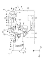
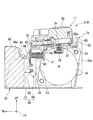
図1、図2は、サーマルプリンタ1の断面図であって、図1はプリンタカバー6の開位置を示し、図2はプリンタカバー6の閉位置を示す。なお、図中において、FRは前方を、LHは左方を、UPは上方をそれぞれ示す。
図1、図2に示すように、本実施形態のサーマルプリンタ1は、互いに分離可能に組み合わされるプラテンユニット2及びヘッドユニット3を有する印字ユニット9と、印字ユニット9が組み込まれるとともに、記録紙Pが巻回されたロール紙Rを収容するケーシング4と、を備えている。
Next, an embodiment of the present invention will be described based on the drawings.
[Thermal printer]
1 and 2 are cross-sectional views of the thermal printer 1. FIG. 1 shows the open position of the printer cover 6 and FIG. 2 shows the closed position of the printer cover 6. As shown in FIG. In the drawing, FR indicates the front, LH indicates the left, and UP indicates the upper.
As shown in FIGS. 1 and 2, the thermal printer 1 of the present embodiment includes a
ケーシング4は、ロール紙Rを収容するロール紙収容部5aが形成されたケーシング本体5と、ロール紙収容部5aを開閉するプリンタカバー6と、を備えている。
プリンタカバー6は、ヒンジ部7を介してケーシング本体5に回動可能に連結されている。また、図2に示すように、プリンタカバー6の閉位置において、ロール紙収容部5aの開口縁と、プリンタカバー6の先端部と、の間には、記録紙Pを外部(上方)に排出する排出口8が形成されている。
The casing 4 is provided with a casing main body 5 in which a roll
The printer cover 6 is rotatably connected to the casing main body 5 via the hinge portion 7. Further, as shown in FIG. 2, the recording sheet P is discharged to the outside (upward) between the opening edge of the roll
上述したプラテンユニット2は、プラテンローラ10及び固定刃13が主に組み込まれたユニットであって、プリンタカバー6の内面における先端部に組み付けられている。このため、プラテンユニット2は、プリンタカバー6の開閉動作に伴って移動することで、ヘッドユニット3に対して分離可能に組み合わされる。
一方、ヘッドユニット3は、例えばサーマルヘッド12及び可動刃(カッター機構)11が主に組み込まれたユニットであって、ケーシング本体5に組み付けられている。図示の例において、ヘッドユニット3は、ロール紙収容部5aに隣接して配設された内部プレート5b上に、サーマルヘッド12をロール紙収容部5a側に向けた状態で固定されている。
The platen unit 2 described above is a unit in which the
On the other hand, the
なお、プリンタカバー6が閉まり、プラテンユニット2とヘッドユニット3とが組み合わされたときに、図2に示すように、プラテンローラ10に対してサーマルヘッド12が押し付けられるとともに、可動刃11と固定刃13とが所定位置に位置決めされる。なお、固定刃13及び可動刃11によりカッターユニット14を構成している。
When the printer cover 6 is closed and the platen unit 2 and the
<印字ユニット>
図3は印字ユニット9の側面図であり、図4は印字ユニット9の分解斜視図である。図5は図4のV−V線に沿う断面図である。
図3〜図5に示すように、プラテンユニット2は、上述したプラテンローラ10及び固定刃13と、これらプラテンローラ10及び固定刃13を支持するプラテンフレーム21と、プラテンフレーム21を支持するサブフレーム22と、を備えている。
<Printing unit>
FIG. 3 is a side view of the
As shown in FIGS. 3 to 5, the platen unit 2 includes the above-described
まず、プラテンフレーム21は、金属等の板材が屈曲形成されてなり、前後方向から見た正面視で下方に向けて開放されたコ字状を呈している。具体的に、プラテンフレーム21は、左右方向の両端部に位置する一対の軸支持部24と、左右方向に沿って延びるとともに、各軸支持部24間を架け渡す連結部25と、を備えている。
各軸支持部24の後端部には、プラテンローラ10の後述する軸受29が保持されている。また、各軸支持部24のうち、左右方向の一端側(図示の例では左側)に位置する軸支持部24の下端部には、左右方向の外側に向けて突出する突出片26が形成されている。
First, the
At the rear end of each
プラテンローラ10は、プリンタカバー6の閉位置においてプラテンユニット2とヘッドユニット3とが組み合わされたときに、記録紙Pを間に挟んだ状態でサーマルヘッド12に外周面が接触するように配置されている。具体的に、プラテンローラ10は、左右方向に沿って延びるプラテン軸27と、プラテン軸27に外装されたゴム等からなるローラ本体28と、を備えている。
When the platen unit 2 and the
プラテン軸27の両端部には、軸受29がそれぞれ外装されている。各軸受29は、上述したようにプラテンフレーム21に保持され、これら軸受29を介してプラテンローラ10がプラテンフレーム21に回転可能に支持されている。
また、プラテン軸27の他端部(右側端部)には、プラテン用歯車31が装着されている(図4参照)。このプラテン用歯車31は、プラテンユニット2とヘッドユニット3とが組み合わされたとき、ヘッドユニット3側の後述するプラテン用輪列機構53(図4参照)に噛合して、プラテンローラ10に回転力を伝達する。これにより、プラテンローラ10と、サーマルヘッド12と、の間で記録紙Pを挟み込みながら紙送りすることが可能とされている。
The platen gear 31 is attached to the other end (right end) of the platen shaft 27 (see FIG. 4). When the platen unit 2 and the
固定刃13は、左右方向に沿って延在する板状とされ、その刃先を後方に向けた状態でプラテンフレーム21の連結部25上に固定されている。
The fixed
サブフレーム22は、プラテンフレーム21よりも一回り大きくなっており、プラテンフレーム21を上方及び左右方向の両側から囲繞している。具体的に、サブフレーム22は、左右方向の両側に位置する側壁部33と、各側壁部33間を連結する基部34と、を有している。
各側壁部33の後端部には、プラテンローラ10の各軸受29が各別に遊挿されている。
The
At the rear end of each
プラテンフレーム21とサブフレーム22との間には、プラテン軸27周りにプラテンフレーム21をサブフレーム22から離間する方向(下方)に向けて付勢(与圧)する一対の与圧機構37が介在している。各与圧機構37は、例えば上下方向に沿って延びるコイルばね等からなり、その下端部がサブフレーム22に各別に連結され、上端部がプラテンフレーム21の連結部25に連結されている。
Between the
(ヘッドユニット)
図3〜図5に示すように、ヘッドユニット3は、上述したサーマルヘッド12を有するヘッドブロック38及び可動刃11と、これらヘッドブロック38及び可動刃11を着脱可能に支持するヘッドフレーム41と、を備えている。
(Head unit)
As shown in FIGS. 3 to 5, the
ヘッドフレーム41は、金属等の板材が屈曲形成されてなり、前後方向から見た正面視で上方に向けて開口するコ字状を呈している。
ヘッドフレーム41のうち、左右方向の両側に位置する一対の側壁部42a,42bには、プラテンローラ10の軸受29が各別に係合される係合凹部44が形成されている。これら係合凹部44は、上方に向けて開口するとともに、前後方向に沿う幅が下方に向かうに従い漸次縮小している。また、係合凹部44の内周縁には、閉位置において、プラテンローラ10の軸受29に上方から係合するストッパ部45が、後方に向けて突設されている。
The
In the
ヘッドフレーム41の前部において、側壁部42a,42b間に位置する部分には、ガイド部材48(図4参照)が設けられている。ガイド部材48には、記録紙Pをサーマルヘッド12まで案内するとともに、閉位置において、上述したプラテンローラ10のローラ本体28が上方から収容されるガイド通路48aが形成されている。
At a front portion of the
側壁部42a,42bの後部(係合凹部44よりも後方に位置する部分)には、上方に向けて突出する第1係止片51が形成されている。第1係止片51は、左右方向から見た側面視で後方に向けて屈曲されたL字状を呈し、可動刃11の後述するフレーム用取付片85が差し込み可能とされている。
側壁部42a,42bのうち、第1係止片51よりも後方に位置する部分(側壁部42a,42bの後端部)には、上方に向けて突出する第2係止片52が形成されている。第2係止片52は、左右方向から見た側面視で前方に向けて屈曲されたL字状を呈し、後述する支持部材71のフレーム用取付片77が差し込み可能とされている。なお、図示の例において、第2係止片52の上端縁は、前方に向かうに従い下方に向けて延びるテーパ部52aとされている。
A
A
図4に示すように、各側壁部42a,42bのうち、右側の側壁部42aには、プラテンユニット2とヘッドユニット3とが互いに組み合わされた際に、プラテンユニット2のプラテン用歯車31に噛合するプラテン用輪列機構53が設けられている。このプラテン用輪列機構53は、ヘッドフレーム41に搭載されたプラテン用モータ54(図5参照)に接続されている。プラテン用モータ54を適宜回転させることで、その回転力がプラテン用輪列機構53を介してプラテン用歯車31に伝達され、プラテンローラ10が回転する。
As shown in FIG. 4, when the platen unit 2 and the
図6は、ヘッドブロック38、可動刃11、及び支持部材71の分解斜視図である。
図4〜図6に示すように、ヘッドブロック38は、ヘッドフレーム41に配設された回動軸55に回動可能に支持されたヘッドサポート56と、ヘッドサポート56に固定された上述したサーマルヘッド12と、を備えている。
回動軸55は、左右方向に沿って延設されるとともに、その両端部がヘッドフレーム41の各側壁部42a,42bに各別に支持されている。図3に示すように、回動軸55のうち、左側の側壁部42bよりも外側に位置する部分には、プラテンユニット2とヘッドユニット3との組み合わせを解除する解除レバー61が配設されている。解除レバー61は、左右方向から見た側面視でV字状とされ、その頂部が回動軸55周りに回動可能に支持されている。解除レバー61のうち、頂部に対して一端側に位置する部分にはケーシング本体5に設けられた図示しないレバー部材が係止され、他端側に位置する部分はプラテンフレーム21の上述した突出片26に下方から当接するようになっている。これにより、解除レバー61は、レバー部材の操作に連動して回動し、突出片26を介してプラテンユニット2を上方に向けて押し上げることで、ヘッドユニット3からプラテンユニット2を分離させる。
FIG. 6 is an exploded perspective view of the
As shown in FIGS. 4 to 6, the
The
図4〜図6に示すように、ヘッドサポート56は、金属等の板材が屈曲形成されてなり、ヘッドフレーム41の内側に配置されている。具体的に、ヘッドサポート56は、サーマルヘッド12が固定されるヘッド支持壁62と、ヘッド支持壁62における左右方向の両端部から後方に向けて各別に屈曲された一対のステー63と、を備えている。
As shown in FIGS. 4 to 6, the
ヘッド支持壁62は、前後方向を厚さ方向とするとともに、左右方向に延設されている。ヘッド支持壁62は、その上部がガイド通路48aの内側に露出している。
The
ステー63は、その下端部がヘッド支持壁62よりも下方に位置している。ステー63の下端部には、上述した回動軸55を収容する収容凹部64が形成されている。収容凹部64は、左右方向から見た側面視でC字状とされ、前方に向けて開放されている。これにより、ヘッドサポート56は、回動軸55周りに前後方向(プラテンローラ10に接近離間する方向)に回動可能とされるとともに、回動軸55に着脱可能に装着されている。なお、図示の例において、ステー63の下端縁(収容凹部64よりも下方に位置する部分)は、後方に向かうに従い下方に向けて傾斜するテーパ状とされている。
The lower end portion of the
ヘッド支持壁62における左右方向の両端部のうち、上述したステー63よりも上方に位置する部分には、後方に向けてストッパ壁66が突設されている。ストッパ壁66は、ヘッドフレーム41の規制部67に係止され、ヘッドブロック38の回動範囲を制限する。
A
図4、図6に示すように、サーマルヘッド12は、左右方向(記録紙Pの紙幅方向)に沿って延在する板状とされ、ヘッド支持壁62の前面に固定されている。サーマルヘッド12の表面には、複数の発熱素子12aがライン状に配列されている。発熱素子12aは、ガイド通路48a内に露出し、閉位置においてプラテンローラ10(ローラ本体28)の外周面に圧接される。
As shown in FIGS. 4 and 6, the
図4〜図6に示すように、側壁部42a,42b上における後部(ヘッドブロック38よりも後方に位置する部分)には、支持部材71がヘッドフレーム41に対して前後方向にスライド移動可能に支持されている。支持部材71は、金属等の板材が屈曲形成されてなり、ヘッドブロック38を後方から支持するとともに、可動刃11をヘッドフレーム41に連結する。支持部材71は、左右方向に沿って延びるとともに、側壁部42a,42bの上端部同士を架け渡すベース部72を備えている。
As shown in FIGS. 4 to 6, the
ベース部72には、ベース部72を上下方向に貫通する一対の切欠き部73(図6参照)が左右方向に並んで形成されている。これら切欠き部73の後端開口縁には、上下方向から見た平面視で切欠き部73内を臨む突片部74が前方に向けて突設されている。突片部74は、左右方向から見た側面視でL字状を呈し、基端部が切欠き部73の後端開口縁から下方に向けて延設されるとともに、先端部が前方に向けて延設されている。突片部74の先端部には、可動刃11を上方に向けて付勢する可動刃付勢部材(第2付勢部材)75が配設されている。可動刃付勢部材75は、例えばコイルばね等からなり、その下端部が突片部74の先端部に連結されるとともに、上端部が切欠き部73を通してベース部72よりも上方に向けて突出している。
In the
ベース部72における左右方向の両端部には、左右方向の外側に向けて突出する可動刃用取付片76及びフレーム用取付片77がそれぞれ一対ずつ形成されている。
可動刃用取付片76は、左右方向から見た側面視で後方に向けて屈曲されたL字状を呈し、可動刃11の後述する支持部材用取付片86が係止される。可動刃用取付片76の後端縁は、上方に向けて凸の曲線状とされ、上方に向かうに従い前方に向けて延びる案内部76aを構成している。なお、側壁部42a,42bのうち、上述した可動刃用取付片76よりも前方に位置する部分には、上方に向けて突出する第1規制突部78が形成されている。第1規制突部78は、支持部材71のスライド移動に伴い可動刃用取付片76が後方から近接または当接可能とされ、支持部材71の前方移動を制限する。
At both end portions in the left-right direction of the
The movable
フレーム用取付片77は、ベース部72のうち、可動刃用取付片76よりも後方に位置する部分に形成され、上方から見た平面視で後方に向けて屈曲されたL字状を呈している。フレーム用取付片77は、ヘッドフレーム41の上述した第2係止片52内で係止され、ヘッドフレーム41に対する支持部材71の移動(上下左右及び後方への移動)が規制されている。なお、側壁部42a,42bのうち、フレーム用取付片77よりも前方に位置する部分には、上方に向けて突出する第2規制突部79が形成されている。第2規制突部79は、支持部材71のスライド移動に伴いフレーム用取付片77が後方から近接または当接可能とされ、支持部材71の前方移動を制限する。
The
ベース部72の後端部には、支持部材71を前後方向にスライド操作させる操作壁80が形成されている。操作壁80は、上方に向けて突出するとともに、ベース部72における左右方向の全域に亘って形成されている。
At the rear end portion of the
可動刃11は、支持部材71を介してヘッドフレーム41に着脱可能に装着されている。具体的に、可動刃11は、可動刃フレーム81と、可動刃フレーム81にスライド可能に支持された可動刃本体82と、可動刃本体82を駆動させる駆動機構(可動刃用モータ)83と、を備えている。
The
可動刃フレーム81における左右方向の両端部には、ヘッドフレーム41の上述した第1係止片51に各別に係止される一対のフレーム用取付片85が形成されている。各フレーム用取付片85は、可動刃フレーム81から左右方向の外側に向けて突設されるとともに、上下方向から見た平面視で前方に向けて屈曲されたL字状を呈している。フレーム用取付片85は、ヘッドフレーム41の第1係止片51内に差し込まれ、ヘッドフレーム41に対する支持部材71の移動(上下左右及び前方)への移動が規制されている。
At both end portions in the left-right direction of the
可動刃フレーム81のうち、フレーム用取付片85よりも後方に位置する部分には、左右方向の外側に向けて突出する支持部材用取付片86が形成されている。支持部材用取付片86は、可動刃フレーム81から左右方向の外側に向けて突設され、上下方向から見た平面視で矩形状を呈している。支持部材用取付片86は、支持部材71の上述した可動刃用取付片76内に収容され、支持部材71に対する可動刃11の移動が規制されている。
At a portion of the
可動刃本体82は、上下方向から見た平面視でV字状とされ、根元から刃先までの長さが両端から中央に向かって漸次短くなるように形成されている。
駆動機構83は、可動刃フレーム81上に搭載された正逆転可能なカッター用モータや、カッター用モータ及び可動刃本体82間に接続される輪列機構等を有している。そして、可動刃本体82は、カッター用モータの駆動力が輪列機構を介して伝達されることで、スライド移動する。
The movable blade
The
ここで、上述した支持部材71は、可動刃11をヘッドフレーム41に連結する連結位置(図3等参照)と、可動刃11がヘッドフレーム41から離脱可能な連結解除位置(図7等参照)と、の間を可動刃11及びヘッドフレーム41に対して前後方向にスライド移動可能とされている。具体的に、連結位置において、支持部材71の可動刃用取付片76は、可動刃11の支持部材用取付片86に前方及び上方から係止され、支持部材71に対する支持部材用取付片86の上方移動を規制している。一方、図7等に示す連結解除位置において、支持部材71の可動刃用取付片76は、可動刃11の支持部材用取付片86と上下方向で重ならない位置まで退避して、可動刃用取付片76と支持部材用取付片86との係止が解除される。これにより、支持部材71に対する可動刃11の上方移動が許容される。
Here, the
ベース部72の前端縁には、下方に向けて延びる受座91が左右方向に間隔をあけて一対形成されている。これら受座91は、ヘッドブロック38のヘッド支持壁62に前後方向で対向配置されている。受座91とヘッド支持壁62との間には、支持部材71とヘッドブロック38を前後方向で離間させる方向に向けて付勢するヘッド付勢部材(第1付勢部材)92が介在している。すなわち、ヘッド付勢部材92は、ヘッドブロック38(サーマルヘッド12)をプラテンローラ10に向けて付勢するとともに、支持部材71を上述した連結位置に向けて付勢している。
At the front end edge of the
また、可動刃11は、支持部材71に配設された上述した可動刃付勢部材75により上方に向けて付勢されている。具体的に、可動刃付勢部材75は、その下端部が支持部材71の上述した突片部74上に連結されるとともに、上端部が可動刃フレーム81の下面に摺動可能に接続され、可動刃11及び支持部材71を上下方向に離間する方向に付勢している。
Further, the
このように構成されたサーマルプリンタ1では、図2、図3に示すように、プリンタカバー6が閉位置とされ、両ユニット2,3が組み合わさった状態において、可動刃11と固定刃13とが所望の位置に配置されるとともに、記録紙Pがプラテンローラ10とサーマルヘッド12との間に挟まれた状態となる。また、この記録紙Pは、可動刃11と固定刃13との間を通過した後、排出口8からケーシング4の外側に引き出された状態となる。さらに、プラテンユニット2側のプラテン用歯車31が、ヘッドユニット3側のプラテン用輪列機構53に噛合する。
In the thermal printer 1 configured as described above, as shown in FIGS. 2 and 3, the
その後、プラテン用モータ54を駆動させて、その回転力をプラテンユニット2のプラテン用歯車31に伝達させる。これにより、プラテンローラ10を回転させることができ、サーマルヘッド12との間で記録紙Pを挟み込みながら紙送りさせることができる。また、この紙送りと同時に、サーマルヘッド12の発熱素子12aを適宜発熱させることで、紙送りされる記録紙Pに対して各種の文字や図形等を明瞭に印字することができる。
Thereafter, the
印字された記録紙Pは固定刃13と可動刃11との間を通過する。そして、記録紙Pが所定の長さ通過した後、駆動機構83を駆動させ、可動刃本体82を固定刃13に向けてスライドさせる。これにより、固定刃13と可動刃11との間で記録紙Pを切断できる。その結果、切断した記録紙Pを、レシートやチケット等として使用することができる。
The printed recording paper P passes between the fixed
(ヘッドブロックの交換方法)
次に、上述したサーマルプリンタ1の作用として、ヘッドブロック38の交換方法について説明する。
まず、プリンタカバー6の開位置とする。具体的に、図3に示すように、ケーシング本体5に設けられた図示しないレバー部材を操作すると、レバー部材の操作に連動して、解除レバー61が回動軸55周りに回動する。すると、解除レバー61が突出片26を介してプラテンユニット2を上方に向けて押し上げる。
(How to replace the head block)
Next, as a function of the thermal printer 1 described above, a method of replacing the
First, the printer cover 6 is in the open position. Specifically, as shown in FIG. 3, when the lever member (not shown) provided on the casing main body 5 is operated, the
プラテンローラ10は、ローラ本体28の外周面がヘッドブロック38をヘッド付勢部材92の付勢力に抗する方向に向けて押圧しながら係合凹部44から離脱していく。そして、プラテンローラ10の軸受29がストッパ部45を乗り越えることで、軸受29とストッパ部45との係合が解除され、図4に示すように両ユニット2,3の組み合わせが解除される。その後、図1に示すように、プリンタカバー6を引き上げることで、プリンタカバー6が開位置となる。なお、両ユニット2,3の組み合わせが解除されると、ヘッドブロック38がヘッド付勢部材92の付勢力によって前方に向けて回動する。その後、ヘッドブロック38は、ストッパ壁66がヘッドフレーム41の規制部67に当接することで、ヘッドフレーム41に対して位置決めされる。
The
図7〜図10は、可動刃11の着脱操作を説明するための説明図であって、図7,9はヘッドユニットの側面図、図8,10はヘッドユニットの断面図である。
次に、ヘッドユニット3からヘッドブロック38を取り外すには、まずヘッドユニット3から可動刃11を取り外す。具体的には、図7、図8に示すように、操作壁80を介して支持部材71を前方(ヘッド付勢部材92の付勢力に抗する方向)に向けて押し込み、支持部材71を連結解除位置に移動させる。すると、支持部材71は、可動刃付勢部材75の上端部が可動刃フレーム81の下面上を摺動しながら、ヘッドフレーム41に対して前方にスライド移動する。支持部材71が前方移動すると、支持部材71の可動刃用取付片76が可動刃11の支持部材用取付片86の上方から退避し、可動刃用取付片76と支持部材用取付片86との係止が解除される。これにより、支持部材71が連結解除位置となり、ヘッドフレーム41に対する可動刃11の上方移動が許容される。
7 to 10 are explanatory views for explaining the attaching / detaching operation of the
Next, to remove the
支持部材71が連結解除位置になると、可動刃11が可動刃付勢部材75の復元力によって押し上げられる。これにより、可動刃11が支持部材71に対して上方移動することで、支持部材用取付片86が支持部材71の可動刃用取付片76から離脱し、可動刃11と支持部材71との連結が解除される。なお、可動刃11が支持部材71に対して上方移動する過程において、可動刃11のフレーム用取付片85はヘッドフレーム41の第1係止片51内への差し込まれた状態を維持する。そのため、可動刃11はフレーム用取付片85と第1係止片51との接触部分を支点として回動しながら上方移動する。
When the
その後、図9、図10に示すように、可動刃11を引き抜き、フレーム用取付片85を第1係止片51から離脱させる。これにより、可動刃11がヘッドフレーム41及び支持部材71から取り外される。
Thereafter, as shown in FIGS. 9 and 10, the
図11は、支持部材71の着脱操作を説明するための説明図であって、ヘッドユニット3の側面図である。
次に、図11に示すように、ヘッドフレーム41から支持部材71を取り外す。具体的には、上述した連結解除位置から支持部材71をさらに前方にスライド移動させる。すると、支持部材71のフレーム用取付片77が、ヘッドフレーム41の第2係止片52内から退避し、支持部材71とヘッドフレーム41との連結が解除される。その後、支持部材71を上方に向けて押し上げることで、支持部材71がヘッドフレーム41から取り外される(図12参照)。なお、本実施形態において、ヘッド付勢部材92は支持部材71とともにヘッドフレーム41から取り外される。
FIG. 11 is an explanatory view for explaining the attaching / detaching operation of the
Next, as shown in FIG. 11, the
図12〜図14は、ヘッドブロック38の着脱操作を説明するための説明図であって、ヘッドユニット3の断面図である。
次に、図12、図13に示すように、ヘッドフレーム41からヘッドブロック38を取り外す。具体的には、ヘッドフレーム41に対してヘッドブロック38を後方に移動させ、回動軸55をヘッドサポート56の収容凹部64から離脱させる。
12 to 14 are explanatory views for explaining the attaching and detaching operation of the
Next, as shown in FIGS. 12 and 13, the
次に、図14に示すように、ヘッドブロック38を上方に引き上げる。すると、ヘッドブロック38は、ヘッドフレーム41の側壁部42a,42b間の隙間を通してヘッドフレーム41から引き抜かれる。
以上により、ヘッドユニット3からヘッドブロック38が取り外される。
Next, as shown in FIG. 14, the
Thus, the
なお、新たなヘッドブロック38をヘッドユニット3に取り付ける場合には、上述した取り外し動作と逆の動作を行う。すなわち、ヘッドフレーム41の側壁部42a,42b間の隙間を通してヘッドフレーム41内にヘッドブロック38を差し入れた後、ヘッドサポート56の収容凹部64内に回動軸55を進入させる。
When a
次に、ヘッドフレーム41に対して支持部材71を装着する。具体的には、ヘッド付勢部材92の前端部をヘッドサポート56のヘッド支持壁62に後方から接触させた状態で、支持部材71のフレーム用取付片77をヘッドフレーム41の第2係止片52内に差し込む。これにより、支持部材71がヘッドフレーム41の側壁部42a,42b上に装着される。
Next, the
その後、ヘッドフレーム41に対して可動刃11を装着する。具体的には、可動刃11のフレーム用取付片85をヘッドフレーム41の第1係止片51内に差し込んだ後、可動刃11を下方に向けて押し込む。すると、可動刃11の支持部材用取付片86が支持部材71における可動刃用取付片76の案内部76aに接触する。この状態でさらに可動刃11を下方に向けて押し込む。すると、可動刃11の押し込み力によって、支持部材用取付片86が可動刃用取付片76の案内部76a上を摺動しながら、支持部材71が前方(連結解除位置)にスライド移動するとともに、可動刃11が下方に移動する。
Thereafter, the
そして、支持部材用取付片86が可動刃用取付片76の後端縁を乗り越えると、支持部材71がヘッド付勢部材92の復元力によって後方(連結位置)に向けてスライド移動する。これにより、支持部材用取付片86が可動刃用取付片76に係止され、可動刃11とヘッドフレーム41が支持部材71を介して装着される。
以上により、ヘッドブロック38を交換することができる。
Then, when the support
Thus, the
このように、本実施形態では、支持部材71が連結位置及び連結解除位置の間で移動可能とされるとともに、支持部材71を連結位置に向けて付勢するヘッド付勢部材92を備える構成とした。
この構成によれば、支持部材71が連結位置に付勢されているため、支持部材71を介して可動刃11とヘッドフレーム41との連結状態を維持することができる。一方、可動刃11の取り外し時には、支持部材71を連結解除位置に向けて移動させるだけで、支持部材71を介した可動刃11とヘッドフレーム41との連結状態を簡単に解除できる。これにより、例えばその後のヘッドブロック38の交換作業に簡単に移行することができ、メンテナンス時間の短縮を図ることができる。また、従来のようにねじ等の締結部材を用いて可動刃11とヘッドフレーム41とを連結する場合と異なり、可動刃11の着脱作業に工具を用いる必要がない。そのため、メンテナンス性を向上させることができる。
特に、本実施形態では、サーマルヘッド12をプラテンローラ10に向けて付勢するヘッド付勢部材92によって支持部材71を連結位置に向けて付勢するため、ヘッド加圧及び支持部材71の付勢の双方をヘッド付勢部材92により行うことができる。これにより、ヘッド加圧及び支持部材71の付勢それぞれを別々の付勢部材を用いて行う場合に比べて、部品点数の増加を抑制し、低コスト化を図ることができる。
As described above, in the present embodiment, the
According to this configuration, since the
In particular, in the present embodiment, the
また、上述したように可動刃11の着脱作業を簡単に行うことができるので、ヘッドブロック38の交換作業を全体として簡単に行うことができる。
さらに、支持部材71がヘッド付勢部材92の付勢方向に沿ってスライド移動可能とされているため、例えば支持部材71が回動等により移動する場合に比べて連結位置及び連結解除位置間の変位量を小さくできる。これにより、印字ユニット9の小型化やレイアウト性の向上を図ることができる。
Further, since the
Furthermore, since the
また、可動刃11のうち、支持部材用取付片86を介して支持部材71の可動刃用取付片76に係止され、フレーム用取付片85を介してヘッドフレーム41の第1係止片51内に差し込まれるため、可動刃11がヘッドフレーム41及び支持部材71の双方に連結されることになる。そのため、ヘッドフレーム41に対して所望の位置に可動刃11を装着することができる。
The
また、可動刃11をヘッドフレーム41から離脱する方向(上方)に向けて付勢する可動刃付勢部材75を備えているため、支持部材71が連結解除位置にあるときに、可動刃11が自動的に支持部材71から離脱することになる。そのため、支持部材71を連結解除位置に押し込んだ状態で、可動刃11を支持部材71から離脱させる等の手間が必要なく、支持部材71の連結解除位置への押し込み操作のみのワンタッチで可動刃11を支持部材71から離脱させることができる。これにより、更なるメンテナンス性の向上を図ることができる。
Further, since the movable
そして、本実施形態のサーマルプリンタ1では、上述した印字ユニット9を備えているため、メンテナンス性に優れたサーマルプリンタ1を提供できる。
And since the thermal printer 1 of this embodiment is equipped with the
なお、本発明の技術範囲は上述した実施形態に限定されるものではなく、本発明の趣旨を逸脱しない範囲において種々の変更を加えることが可能である。 The technical scope of the present invention is not limited to the above-described embodiment, and various modifications can be made without departing from the scope of the present invention.
例えば、上述した実施形態では、上述した実施形態では、プラテンフレーム21に固定刃13が設けられ、ヘッドフレーム41に可動刃11が設けられた構成について説明したが、これに限られない。すなわち、可動刃11がプラテンフレーム21に設けられ、本発明のカッター機構として固定刃13がヘッドフレーム41に設けられた構成であっても構わない。
For example, in the embodiment described above, although the fixed
また、上述した実施形態では、支持部材71がスライド移動する構成について説明したが、これに限らず、ヘッドフレーム41に対して移動する構成であれば、回動等、適宜設計変更が可能である。
また、上述した実施形態では、可動刃付勢部材75が支持部材71に設けられた構成について説明したが、これに限らず、ヘッドフレーム41に設けられていても構わない。
さらに、上述した実施形態では、可動刃11が支持部材71及びヘッドフレーム41の双方に係止される構成について説明したが、少なくとも支持部材71に係止されていれば構わない。
In the embodiment described above, the configuration in which the
In the embodiment described above, the movable
Furthermore, in the embodiment described above, the configuration in which the
また、上述した実施形態では、ヘッドサポート56の収容凹部64が後方に向けて開放された構成について説明したが、これに限られない。例えば、ヘッドサポート56に形成された貫通孔内に回動軸55が挿入される構成であっても構わない。
Further, in the embodiment described above, the configuration in which the
次に、本発明の他の実施形態を図面に基づいて説明する。なお、本実施形態において、上述した実施形態と同一の部材には同一の符号を付して、その説明を省略する。
図15は、他の実施形態に係る印字ユニットを示す斜視図である。また、図16は、この他の実施形態に係る印字ユニットのヘッドブロック、可動刃、及び支持部材の分解斜視図であり、図17は、図16の可動刃を底面から見た斜視図である。さらに、図18は、この他の実施形態に係る印字ユニットを示す、図15のA−A線に沿う断面図である。
Next, another embodiment of the present invention will be described based on the drawings. In addition, in this embodiment, the same code | symbol is attached | subjected to the member same as embodiment mentioned above, and the description is abbreviate | omitted.
FIG. 15 is a perspective view showing a printing unit according to another embodiment. FIG. 16 is an exploded perspective view of a head block, a movable blade, and a support member of the printing unit according to the other embodiment, and FIG. 17 is a perspective view of the movable blade of FIG. . Furthermore, FIG. 18 is a cross-sectional view taken along the line A-A of FIG. 15 showing the printing unit according to the other embodiment.
本実施形態の印字ユニット9Aは、互いに分離可能に組み合わされるプラテンユニット2A及びヘッドユニット3Aを有している。上述した実施形態のプラテンユニット2は、プラテンフレーム21とサブフレーム22との間に、プラテン軸27周りにプラテンフレーム21をサブフレーム22から離間する方向(下方)に向けて付勢(与圧)する与圧機構37を、両側部にそれぞれ具備していたが、本実施形態のプラテンユニット2Aは、片側部のみに与圧機構37を具備している。プラテンフレーム21およびサブフレーム22が十分な強度を有していれば、与圧機構37を片側に1つのみ備えていても、上述した実施形態と同様の作用効果を得ることはできる。
The
ヘッドユニット3Aは、サーマルヘッド12を有するヘッドブロック38及び可動刃11Aと、これらヘッドブロック38及び可動刃11Aを着脱可能に支持するヘッドフレーム41と、ヘッドブロック38を後方から支持するとともに、可動刃11Aをヘッドフレーム41に連結する支持部材71Aと、を備えている。
The
本実施形態のヘッドユニット3Aでは、支持部材71Aを前後方向にスライド操作させる操作壁80Aが、ベース部72の後端部を下方に向けて突出して形成されている。この構成により、可動刃11Aの着脱操作時に操作壁80Aを介して付与される押圧力が、ヘッド付勢部材92の付勢力に抗する方向に対して効果的に加えられることになるので、支持部材71Aを容易に連結解除位置に押し込むことができる。
In the
図17に示すように、可動刃11Aは、支持部材71Aと対向する底面93の可動刃用モータ83Aの下部に位置する箇所に形成された切欠部94を有している。そして、この切欠部94を介して底面93から露出された可動刃用モータ83Aの一部には、導電性スポンジ部材75Aが取り付けられている。この導電性スポンジ部材75Aは、上述した可動刃付勢部材(第2付勢部材)75と同様に、可動刃11Aが支持部材71Aに組み付けられた際に、可動刃11Aを上方に向けて付勢する。これにより、支持部材71Aが連結解除位置にあるときに、可動刃11Aを自動的に支持部材71Aから離脱させることができる。
As shown in FIG. 17, the
また、本実施形態のヘッドユニット3Aでは、可動刃11Aが支持部材71Aに組み付けられた際に、導電性スポンジ部材75Aが、金属材料からなる支持部材71Aと可動刃用モータ83Aとに接した状態で配設される。これにより、可動刃用モータ83Aの電気的導通が確保されることになるので、新たな部材を追加することなく可動刃用モータの信頼性の向上を図ることができる。
Further, in the
次に、上述した他の実施形態の変形例を図面に基づいて説明する。なお、本変形例において、上述した実施形態と同一の部材には同一の符号を付して、その説明を省略する。
図19は、他の実施形態に係る印字ユニットの変形例を示す斜視図である。また、図20は、この印字ユニットの変形例のヘッドブロック、可動刃、及び支持部材を示す分解斜視図であり、図21は、図20の可動刃を底面から見た斜視図である。さらに、図22は、この印字ユニットの変形例を示す、図19のB−B線に沿う断面図である。
Next, modifications of the above-described other embodiment will be described based on the drawings. In addition, in this modification, the same code | symbol is attached | subjected to the member same as embodiment mentioned above, and the description is abbreviate | omitted.
FIG. 19 is a perspective view showing a modification of the printing unit according to the other embodiment. FIG. 20 is an exploded perspective view showing a head block, a movable blade and a support member of a modification of the printing unit, and FIG. 21 is a perspective view of the movable blade of FIG. 20 as viewed from the bottom. Furthermore, FIG. 22 is a cross-sectional view taken along the line B-B of FIG. 19 showing a modification of the printing unit.
本実施形態の印字ユニット9Bは、互いに分離可能に組み合わされるプラテンユニット2A及びヘッドユニット3Bを有している。また、ヘッドユニット3Bは、サーマルヘッド12を有するヘッドブロック38及び可動刃11Bと、これらヘッドブロック38及び可動刃11Bを着脱可能に支持するヘッドフレーム41と、ヘッドブロック38を後方から支持するとともに、可動刃11Bをヘッドフレーム41に連結する支持部材71Bと、を備えている。
The
図21に示すように、可動刃11Bは、上述した他の実施形態と同様、支持部材71Bと対向する底面93の可動刃用モータ83Bの下部に位置する箇所に形成された切欠部94を有している。また、図20に示すように、支持部材71Bは、ベース部72上の切欠部94に対応する位置に金属製の板バネ75Bを備えている。この板バネ75Bは、上述した可動刃付勢部材(第2付勢部材)75と同様に、可動刃11Bが支持部材71Bに組み付けられた際に、可動刃11Bを上方に向けて付勢する。これにより、支持部材71Bが連結解除位置にあるときに、可動刃11Bを自動的に支持部材71Bから離脱させることができる。
As shown in FIG. 21, the
また、この変形例に係るヘッドユニット3Bにおいても、上述した他の実施形態と同様、可動刃11Bが支持部材71Bに組み付けられた際に、金属製の板バネ75Bが、金属材料からなる支持部材71Bと可動刃用モータ83Bとに接した状態で配設される。これにより、可動刃用モータ83Bの電気的導通が確保されることになるので、新たな部材を追加することなく可動刃用モータの信頼性の向上を図ることができる。
Further, also in the
その他、本発明の趣旨を逸脱しない範囲で、上述した実施形態における構成要素を周知の構成要素に置き換えることは適宜可能であり、また、上述した各変形例を適宜組み合わせても構わない。 In addition, it is possible to replace the components in the above-described embodiment with known components as appropriate without departing from the spirit of the present invention, and the above-described modifications may be combined as appropriate.
1 サーマルプリンタ
2 プラテンユニット
3,3A,3B ヘッドユニット
9,9A,9B 印字ユニット
10 プラテンローラ
11,11A,11B 可動刃(カッター機構)
12 サーマルヘッド
41 ヘッドフレーム
71,71A,71B 支持部材
75,75A,75B 可動刃付勢部材(第2付勢部材)
76 可動刃用取付片
77 フレーム用取付片
83,83A,83B 駆動機構(可動刃用モータ)
85 フレーム用取付片
86 支持部材用取付片
92 ヘッド付勢部材(第1付勢部材)
DESCRIPTION OF SYMBOLS 1 Thermal printer 2
12
76 Movable
85 Mounting piece for
Claims (8)
前記記録紙に対して印字を行うサーマルヘッドを有し、前記プラテンユニットに分離可能に組み合わされるヘッドユニットと、
を備えた印字ユニットにおいて、
前記ヘッドユニットは、
ヘッドフレームと、
前記記録紙を切断するカッター機構と、
前記カッター機構と前記ヘッドフレームとの間に配設された支持部材であって、該支持部材の介入によって前記カッター機構が前記ヘッドフレームに着脱可能に取り付けられ、前記カッター機構を前記ヘッドフレームに連結する連結位置、及び前記カッター機構が前記ヘッドフレームから離脱可能な連結解除位置の間で移動可能とされた支持部材と、
前記サーマルヘッドと前記支持部材との間に介在し、前記サーマルヘッドを前記プラテンローラに向けて付勢するとともに、前記支持部材を前記連結位置に向けて付勢する第1付勢部材と、
を備えていることを特徴とする印字ユニット。 A platen unit having a platen roller for feeding a recording sheet;
A head unit having a thermal head that performs printing on the recording paper, and that is detachably combined with the platen unit;
In the printing unit provided with
The head unit is
With the head frame,
A cutter mechanism for cutting the recording paper;
A support member disposed between the cutter mechanism and the head frame, wherein the cutter mechanism is removably attached to the head frame by the intervention of the support member, and the cutter mechanism is coupled to the head frame And a support member movable between the head frame and the disconnected position where the cutter mechanism is detachable from the head frame.
A first biasing member interposed between the thermal head and the support member to bias the thermal head toward the platen roller and bias the support member toward the connection position;
A printing unit comprising:
請求項1に記載の印字ユニット。 The printing unit according to claim 1, wherein the cutter mechanism is detachably attached to the head frame via the support member.
前記連結解除位置は、前記カッター機構が前記支持部材から切り離され、前記ヘッドフレームから取り外し可能な位置である、
請求項1または2に記載の印字ユニット。 The connection position is a position where the cutter mechanism is coupled to the head frame and the support member with respect to the head frame and the cutter mechanism, and
The uncoupling position is a position where the cutter mechanism is separated from the support member and removable from the head frame.
The printing unit according to claim 1.
請求項1から請求項3の何れか1項に記載の印字ユニット。 The printing unit according to any one of claims 1 to 3, wherein the support member is slidable along the biasing direction of the first biasing member.
前記連結位置において前記支持部材に係止される支持部材用取付片と、
前記ヘッドフレームに差し込まれるフレーム用取付片と、
を備えている
請求項1から請求項4の何れか1項に記載の印字ユニット。 The cutter mechanism
A support member attachment piece which is locked to the support member at the connection position;
A frame mounting piece inserted into the head frame;
The printing unit according to any one of claims 1 to 4, comprising:
を備えている
請求項1から請求項5の何れか1項に記載の印字ユニット。 The printing unit according to any one of claims 1 to 5, further comprising a second biasing member configured to bias the cutter mechanism in a direction in which the cutter mechanism is separated from the head frame.
前記カッター機構は、可動刃を駆動させるモータを備え、
前記モータの少なくとも一部は、前記カッター機構の前記支持部材との対向面から露出され、かつ、
前記第2付勢部材は、導電性材料からなり、前記支持部材と前記モータとに接した状態で配設されている
請求項6に記載の印字ユニット。 The support member is formed of a metal material,
The cutter mechanism comprises a motor for driving the movable blade,
At least a portion of the motor is exposed from the surface of the cutter mechanism facing the support member, and
The printing unit according to claim 6, wherein the second biasing member is made of a conductive material, and is disposed in contact with the support member and the motor.
前記印字ユニットが組み付けられたケーシングと、
を備えていることを特徴とするサーマルプリンタ。 A printing unit according to any one of claims 1 to 7;
A casing in which the printing unit is assembled;
The thermal printer characterized by having.
Priority Applications (6)
| Application Number | Priority Date | Filing Date | Title |
|---|---|---|---|
| TW104139436A TWI655100B (en) | 2014-12-25 | 2015-11-26 | Printing unit and thermal printer |
| US14/974,914 US9545800B2 (en) | 2014-12-25 | 2015-12-18 | Printing unit and thermal printer |
| CN201521075602.XU CN205255763U (en) | 2014-12-25 | 2015-12-22 | Print unit and thermal printer |
| CN201510970377.4A CN105730018B (en) | 2014-12-25 | 2015-12-22 | Print unit and thermal printer |
| EP15202439.4A EP3037270B1 (en) | 2014-12-25 | 2015-12-23 | Printing unit and thermal printer |
| KR1020150185283A KR102429223B1 (en) | 2014-12-25 | 2015-12-23 | Printing unit and thermal printer |
Applications Claiming Priority (2)
| Application Number | Priority Date | Filing Date | Title |
|---|---|---|---|
| JP2014262942 | 2014-12-25 | ||
| JP2014262942 | 2014-12-25 |
Publications (3)
| Publication Number | Publication Date |
|---|---|
| JP2016120708A JP2016120708A (en) | 2016-07-07 |
| JP2016120708A5 JP2016120708A5 (en) | 2018-06-28 |
| JP6521766B2 true JP6521766B2 (en) | 2019-05-29 |
Family
ID=56327965
Family Applications (1)
| Application Number | Title | Priority Date | Filing Date |
|---|---|---|---|
| JP2015131487A Active JP6521766B2 (en) | 2014-12-25 | 2015-06-30 | Printing unit and thermal printer |
Country Status (3)
| Country | Link |
|---|---|
| JP (1) | JP6521766B2 (en) |
| KR (1) | KR102429223B1 (en) |
| TW (1) | TWI655100B (en) |
Families Citing this family (3)
| Publication number | Priority date | Publication date | Assignee | Title |
|---|---|---|---|---|
| JP7375303B2 (en) * | 2019-01-21 | 2023-11-08 | セイコーエプソン株式会社 | printing device |
| JP7178279B2 (en) | 2019-01-29 | 2022-11-25 | 富士通コンポーネント株式会社 | printer device |
| JP7287818B2 (en) * | 2019-03-29 | 2023-06-06 | 富士通コンポーネント株式会社 | printer device |
Family Cites Families (12)
| Publication number | Priority date | Publication date | Assignee | Title |
|---|---|---|---|---|
| JP2581427Y2 (en) * | 1992-02-04 | 1998-09-21 | セイコーエプソン株式会社 | Line thermal printer |
| JP3223037B2 (en) * | 1994-03-25 | 2001-10-29 | 株式会社サトー | Thermal printer |
| JP3575144B2 (en) * | 1995-11-21 | 2004-10-13 | セイコーエプソン株式会社 | Cutter device and printer using the same |
| JP2000079597A (en) * | 1998-09-01 | 2000-03-21 | Toshiba Tec Corp | Printer and paper sheet cutting device |
| JP4592925B2 (en) * | 2000-11-10 | 2010-12-08 | シチズンホールディングス株式会社 | Printer |
| JP4580088B2 (en) * | 2000-11-10 | 2010-11-10 | シチズンホールディングス株式会社 | Line thermal printer |
| JP3687912B2 (en) * | 2002-08-29 | 2005-08-24 | 東芝テック株式会社 | Printer unit |
| JP2004098625A (en) * | 2002-09-12 | 2004-04-02 | Toshiba Tec Corp | Printer and commodity data processor |
| JP5196719B2 (en) * | 2005-10-25 | 2013-05-15 | 富士通コンポーネント株式会社 | Thermal printer |
| BRPI0600439B1 (en) * | 2006-03-06 | 2019-01-22 | Bematech S A | thermal printer and its drive method |
| JP2011093115A (en) * | 2009-10-27 | 2011-05-12 | Citizen Holdings Co Ltd | Printer device |
| JP5411095B2 (en) * | 2010-08-31 | 2014-02-12 | スター精密株式会社 | Printer |
-
2015
- 2015-06-30 JP JP2015131487A patent/JP6521766B2/en active Active
- 2015-11-26 TW TW104139436A patent/TWI655100B/en active
- 2015-12-23 KR KR1020150185283A patent/KR102429223B1/en active IP Right Grant
Also Published As
| Publication number | Publication date |
|---|---|
| TWI655100B (en) | 2019-04-01 |
| TW201632367A (en) | 2016-09-16 |
| KR102429223B1 (en) | 2022-08-04 |
| JP2016120708A (en) | 2016-07-07 |
| KR20160078911A (en) | 2016-07-05 |
Similar Documents
| Publication | Publication Date | Title |
|---|---|---|
| EP3037270B1 (en) | Printing unit and thermal printer | |
| US8303200B2 (en) | Printer with movable blade having rack that meshes with pinion when cover is closed | |
| US8662771B2 (en) | Cutter mechanism and printer with a cutter | |
| US8506190B2 (en) | Cutter mechanism and printer with a cutter | |
| US8678689B2 (en) | Printer with a cutter | |
| KR102541304B1 (en) | Printing unit and thermal printer | |
| JP6262429B2 (en) | Printer | |
| US7988374B2 (en) | Sheet cutting device and printer | |
| KR102441776B1 (en) | Printing unit and thermal printer | |
| JP6521766B2 (en) | Printing unit and thermal printer | |
| US8587623B2 (en) | Printer | |
| US20050281606A1 (en) | Printer unit | |
| JP5912047B2 (en) | Thermal printer | |
| CN111070904B (en) | Thermal printer | |
| KR102356765B1 (en) | Printing unit and printer | |
| JP6480223B2 (en) | Printing unit and printer | |
| CN219650853U (en) | Printer core and printer |
Legal Events
| Date | Code | Title | Description |
|---|---|---|---|
| RD04 | Notification of resignation of power of attorney |
Free format text: JAPANESE INTERMEDIATE CODE: A7424 Effective date: 20170913 |
|
| A521 | Request for written amendment filed |
Free format text: JAPANESE INTERMEDIATE CODE: A523 Effective date: 20180509 |
|
| A621 | Written request for application examination |
Free format text: JAPANESE INTERMEDIATE CODE: A621 Effective date: 20180509 |
|
| A977 | Report on retrieval |
Free format text: JAPANESE INTERMEDIATE CODE: A971007 Effective date: 20190117 |
|
| A131 | Notification of reasons for refusal |
Free format text: JAPANESE INTERMEDIATE CODE: A131 Effective date: 20190205 |
|
| A521 | Request for written amendment filed |
Free format text: JAPANESE INTERMEDIATE CODE: A523 Effective date: 20190325 |
|
| TRDD | Decision of grant or rejection written | ||
| A01 | Written decision to grant a patent or to grant a registration (utility model) |
Free format text: JAPANESE INTERMEDIATE CODE: A01 Effective date: 20190409 |
|
| A61 | First payment of annual fees (during grant procedure) |
Free format text: JAPANESE INTERMEDIATE CODE: A61 Effective date: 20190423 |
|
| R150 | Certificate of patent or registration of utility model |
Ref document number: 6521766 Country of ref document: JP Free format text: JAPANESE INTERMEDIATE CODE: R150 |
|
| R250 | Receipt of annual fees |
Free format text: JAPANESE INTERMEDIATE CODE: R250 |
|
| R250 | Receipt of annual fees |
Free format text: JAPANESE INTERMEDIATE CODE: R250 |