JP6521649B2 - Image pickup apparatus, control method thereof and program - Google Patents
Image pickup apparatus, control method thereof and program Download PDFInfo
- Publication number
- JP6521649B2 JP6521649B2 JP2015018305A JP2015018305A JP6521649B2 JP 6521649 B2 JP6521649 B2 JP 6521649B2 JP 2015018305 A JP2015018305 A JP 2015018305A JP 2015018305 A JP2015018305 A JP 2015018305A JP 6521649 B2 JP6521649 B2 JP 6521649B2
- Authority
- JP
- Japan
- Prior art keywords
- focus
- evaluation value
- lens
- focus evaluation
- focus lens
- Prior art date
- Legal status (The legal status is an assumption and is not a legal conclusion. Google has not performed a legal analysis and makes no representation as to the accuracy of the status listed.)
- Active
Links
Images


Landscapes
- Focusing (AREA)
- Automatic Focus Adjustment (AREA)
- Studio Devices (AREA)
Description
本発明は、例えばデジタルカメラやデジタルビデオカメラ等の撮像装置における焦点検出技術の改良に関する。 The present invention relates to an improvement in focus detection technology in an imaging device such as a digital camera or digital video camera.
デジタルカメラ等の撮像装置では、フォーカスレンズを光軸方向に駆動して被写体に焦点を合わせる方法として、CCDセンサ等の撮像素子から得られる画像信号を用いて自動的に合焦動作を行うAF(オートフォーカス)方式が用いられている。このAF方式では、例えばフォーカスレンズを光軸方向に移動させながら予め設定された焦点検出領域内のコントラストを示す焦点評価値をサンプリングし、その焦点評価値が最大となる位置を合焦位置として合焦制御を行う。 In an imaging apparatus such as a digital camera, as a method of driving a focus lens in the optical axis direction to focus on an object, an AF (automatic focusing operation) is performed using an image signal obtained from an imaging element such as a CCD sensor. The auto focus method is used. In this AF method, for example, while moving the focus lens in the optical axis direction, a focus evaluation value indicating the contrast in the focus detection area set in advance is sampled, and the position where the focus evaluation value becomes maximum is set as the in-focus position. Perform focus control.
この合焦制御において、絞りの設定が開放側の場合には、焦点深度が浅くなるため、図10(a)に示すように、焦点評価値のピーク形状は、急峻な山形の曲線となる。一方、絞りの設定が小絞り側の場合には、焦点深度が深くなるため、図10(b)示すように、焦点評価値のピーク形状は、緩やかな山形の曲線となる。そのため、絞りの設定によらず、同じ間隔で焦点評価値のサンプリングを行ってしまうと、開放側では、合焦精度が低下し、小絞り側では、焦点評価値のピーク位置が判別し難くなってしまう。 In this focusing control, when the setting of the aperture is on the open side, the depth of focus becomes shallow, so the peak shape of the focus evaluation value becomes a sharp mountain-shaped curve as shown in FIG. 10A. On the other hand, when the aperture setting is on the small aperture side, the depth of focus becomes deep, so the peak shape of the focus evaluation value becomes a gentle mountain-shaped curve as shown in FIG. 10 (b). Therefore, if the focus evaluation value is sampled at the same interval regardless of the aperture setting, the focusing accuracy decreases on the open side, and the peak position of the focus evaluation value becomes difficult to determine on the small stop side. It will
このような問題を解決するために、絞り設定に応じてレンズ駆動量を変更する技術が提案されている(特許文献1)。しかし、この提案では、図11に示すように、無限遠被写体や至近被写体など、焦点評価値のピーク位置がレンズ端付近に位置する場合には、焦点評価値のピークの片側が制限されてしまう。このため、特に、図11(b)に示す小絞り側では、焦点評価値のピーク形状の判別が困難になる。 In order to solve such a problem, there has been proposed a technique of changing the amount of lens drive in accordance with the aperture setting (Japanese Patent Application Laid-Open No. 2001-147118). However, in this proposal, as shown in FIG. 11, when the peak position of the focus evaluation value is located near the lens end, such as an infinite distance object or a close object, one side of the peak of the focus evaluation value is limited. . For this reason, in particular, on the small stop side shown in FIG. 11B, it is difficult to determine the peak shape of the focus evaluation value.
そこで、絞りの状態に応じて、フォーカスレンズの可動範囲を広く設定する技術が提案されている(特許文献2)。 Therefore, a technique has been proposed in which the movable range of the focus lens is widely set in accordance with the state of the aperture (Japanese Patent Application Laid-Open No. 2008-112118).
しかし、近年、撮像装置の小型化などによる制約により、フォーカスレンズの可動範囲を広げられない場合には、上記特許文献2の技術が適用できない。このため、上記特許文献1と同様に、無限遠被写体や至近被写体など、焦点評価値のピーク位置がレンズ端付近に位置する場合には、焦点評価値のピークの片側が制限され、特に、小絞り側では、焦点評価値のピーク形状の判別が困難になる。 However, in recent years, when the movable range of the focus lens can not be expanded due to the restriction due to the miniaturization of the imaging device, the technology of Patent Document 2 can not be applied. For this reason, as in Patent Document 1, when the peak position of the focus evaluation value is located near the lens end, such as an infinite distance object or a close object, one side of the peak of the focus evaluation value is limited. At the stop side, it is difficult to determine the peak shape of the focus evaluation value.
そこで、本発明は、フォーカスレンズの可動範囲が制限される撮像装置であっても、小絞り状態での被写体の合焦精度の高精度化を実現することができる技術を提供することを目的とする。 Therefore, an object of the present invention is to provide a technology capable of realizing high accuracy in focusing accuracy of an object in a small aperture state even in an imaging apparatus in which the movable range of a focus lens is limited. Do.
上記目的を達成するために、本発明の撮像装置は、撮像素子からの出力信号に基づいて焦点評価値を取得する取得手段と、絞りの駆動およびフォーカスレンズの移動を制御する制御手段と、を備え、前記制御手段は、前記フォーカスレンズが可動範囲の両端のいずれかに到達した場合、前記絞りを所定の絞り値よりも絞っているか否かと、前記到達したレンズ端付近における前記焦点評価値の取得結果に応じて前記フォーカスレンズのレンズ端に向かって前記焦点評価値の増加が続いているか否か、および前記焦点評価値の極大値が検出されたか否かの少なくともいずれか1つと、を判定し、前記絞りを所定の絞り値よりも絞っている状態で前記焦点評価値の増加が続いている、もしくは前記焦点評価値の極大値が検出されたと判定された場合に、前記フォーカスレンズの移動方向を反転した後の前記焦点評価値の取得の際の前記フォーカスレンズの移動速度を反転前の移動速度よりも遅くし、前記焦点評価値の増加が続いている、もしくは前記焦点評価値の極大値が検出されたと判定された場合であっても前記絞りを所定の絞り値よりも絞っていない場合には、前記フォーカスレンズの移動方向を反転した後の前記焦点評価値の取得の際の前記フォーカスレンズの移動速度を変更しないことを特徴とする。 In order to achieve the above object, an image pickup apparatus according to the present invention comprises an acquisition means for acquiring a focus evaluation value based on an output signal from an image pickup device, and a control means for controlling the drive of a diaphragm and the movement of a focus lens. wherein the control means, wherein when the focus lens has reached one of the ends of the movable range, and whether squeezing the diaphragm than the predetermined aperture value, the focal point evaluation value in the vicinity of the lens edge that the arrival Whether or not the focus evaluation value continues to increase toward the lens end of the focus lens according to the acquisition result of at least one of whether or not the local maximum value of the focus evaluation value is detected. It is determined that the focus evaluation value continues to increase while the aperture is narrowed more than a predetermined aperture value, or it is determined that the maximum value of the focus evaluation value is detected. To the slower than the moving speed before reversing the movement speed of the focus lens during acquisition of the focus evaluation value after reversing the moving direction of the focus lens, the increase in the focus evaluation value has continued, Alternatively, even if it is determined that the local maximum value of the focus evaluation value is detected, the focus evaluation after reversing the moving direction of the focus lens if the diaphragm is not narrowed more than a predetermined diaphragm value The moving speed of the focus lens at the time of acquiring a value is not changed .
本発明によれば、フォーカスレンズの可動範囲が制限される撮像装置であっても、小絞り状態での被写体の合焦精度の高精度化を実現することができる。 According to the present invention, even in the case of an imaging apparatus in which the movable range of the focus lens is limited, it is possible to realize high accuracy of focusing accuracy of the subject in the small aperture state.
以下、図面を参照して、本発明の実施形態の一例を説明する。 Hereinafter, an example of an embodiment of the present invention will be described with reference to the drawings.
図1は、本発明の撮像装置の実施形態の一例であるデジタルカメラのシステム構成を示すブロック図である。 FIG. 1 is a block diagram showing a system configuration of a digital camera which is an example of an embodiment of an imaging apparatus of the present invention.
本実施形態のデジタルカメラは、図1に示すように、撮影レンズ101、絞り/シャッタ102及びフォーカスレンズ104を通過した被写体光束が撮像素子107の撮像面に結像して光電変換される。撮像素子107は、CCDセンサやCMOSセンサ等で構成され、光電変換したアナログ画像信号をA/D変換部108に出力する。A/D変換部108は、撮像素子107から出力されたアナログ画像信号をデジタル画像信号に変換する他、撮像素子107の出力ノイズを除去するCDS回路や非線形増幅回路を含む。
In the digital camera of the present embodiment, as shown in FIG. 1, the subject light flux that has passed through the photographing
A/D変換部108から出力されたデジタル画像信号は、画像処理部109に出力されて所定の画像処理が施される。画像処理後の画像データは、フォーマット変換部110及びDRAM111を介して画像記録部112に記録されるとともに、フォーマット変換部110、DRAM111及びVRAM114を介して画像表示部115に表示される。
The digital image signal output from the A /
画像記録部112は、メモリカードなどの記録媒体とそのインタフェースから構成される。DRAM111は、一時的な画像記憶手段としての高速バッファとして、あるいは画像の圧縮伸張における作業用メモリなどに使用される。画像表示部115は、画像表示の他、操作補助のための表示やカメラ状態の表示の他、撮影時には撮影画面と測距領域を表示する。
The
システム制御部113は、撮影シーケンス等のカメラ全体の制御を司る。AE処理部103は、画像処理部109と絞り/シャッタ102に接続され、絞り/シャッタ102の駆動を制御する。AF処理部106は、モータ105を介してフォーカスレンズ104を光軸方向に駆動して合焦制御を行う。
The
操作部116は、ユーザにより操作されるレリーズボタン、電源ボタン、ズームレバー、モード切換えダイアル等により構成される。撮影モードスイッチ117は、マクロモード、遠景モード、スポーツモードなどの撮影モードを選択するためのスイッチであり、ユーザが選択した撮影モードに応じて測距距離範囲やAF動作などを変更する。
The operation unit 116 includes a release button operated by the user, a power button, a zoom lever, a mode switching dial, and the like. The
電源スイッチ118は、電源ボタンが操作されると、オンしてシステムに電源を投入するためのスイッチである。レリーズスイッチ(SW1)119は、レリーズボタンの半押し操作等によりオンしてAFやAE等の撮影準備動作を行うためのスイッチである。レリーズスイッチ(SW2)120は、レリーズボタンの全押し操作等によりオンして、撮影動作を行うためのスイッチである。
The
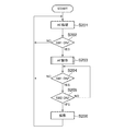
次に、図2乃至図9を参照して、図1に示すデジタルカメラの撮影動作について説明する。図2での各処理は、不図示の記憶部に記憶されたプログラムに従ってシステム制御部113のCPU等により実行される。
Next, the photographing operation of the digital camera shown in FIG. 1 will be described with reference to FIGS. Each process in FIG. 2 is executed by the CPU or the like of the
図2において、ステップS201では、システム制御部113は、画像処理部109の出力に基づきAE処理部103でAE処理を行い、ステップS202に進む。ステップS202では、システム制御部113は、レリーズスイッチ(SW1)119がオンであれば、ステップS203に進み、レリーズスイッチ(SW1)119がオンでなければ、ステップS201に戻る。
In FIG. 2, in step S201, the
ステップS203では、システム制御部113は、AF動作を行い、ステップS204に進む。ここで、AF動作中の露出条件(シャッタ速度、絞り、感度)は、ステップS201のAE処理で決定する。なお、ここでのAF動作の詳細については、図3乃至図9を用いて後述する。
In step S203, the
ステップS204では、システム制御部113は、レリーズスイッチ(SW1)119がオンであれば、ステップS205に進み、レリーズスイッチ(SW1)119がオンでなければ、ステップS201に戻る。ステップS205では、システム制御部113は、レリーズスイッチ(SW2)120がオンであれば、ステップS206に進み、レリーズスイッチ(SW2)120がオンでなければ、ステップS204に戻る。ステップS206では、システム制御部113は、撮影動作を行い、ステップS201に戻る。
In step S204, the
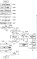
図3は、図2のステップS203におけるAF動作の詳細を説明するフローチャート図である。 FIG. 3 is a flow chart for explaining the details of the AF operation in step S203 of FIG.
図3において、ステップS301では、システム制御部113は、撮像面内に焦点検出領域を設定し、ステップS302に進む。ステップS302では、システム制御部113は、後述する遠端ピーク評価値を0に初期化し、ステップS303に進む。ステップS303では、システム制御部113は、後述する遠端ピーク位置を初期化し、ステップS304に進む。ここで初期化する値は、例えば0にする。
In FIG. 3, in step S301, the
ステップS304では、システム制御部113は、後述する低速スキャンCntを0に初期化し、ステップS305に進む。ステップS305では、システム制御部113は、現在のフォーカスレンズ104の位置を取得し、ステップS306に進む。ステップS306では、システム制御部113は、撮像面に予め設定された焦点検出領域のコントラストを示す焦点評価値を取得し、ステップS307に進む。
In step S304, the
ステップS307では、システム制御部113は、焦点評価値ピーク判定を行い、ステップS308に進む。
In step S307, the
ここで、図4及び図5を参照して、ステップS307での焦点評価値ピーク判定処理の詳細について説明する。 Here, the details of the focus evaluation value peak determination process in step S307 will be described with reference to FIGS. 4 and 5.
図4は、図3のステップS307の焦点評価値ピーク判定処理の詳細を説明するフローチャート図である。図5は、フォーカスレンズ104の位置と焦点評価値との関係を示すグラフ図である。
FIG. 4 is a flowchart for explaining the details of the focus evaluation value peak determination process of step S307 in FIG. FIG. 5 is a graph showing the relationship between the position of the
図4において、ステップS401では、システム制御部113は、サンプリングした焦点評価値の極大値を検出したか否かを判定し、検出した場合は、ステップS402に進み、検出しない場合は、ステップS408に進む。ここでの極大値の検出は、図5に示すように、焦点評価値が増加した後、減少したときに、極大値を検出したと判定する。
In FIG. 4, in step S401, the
ステップS402では、システム制御部113は、IncCntが予め設定したIncCntThr以上であるか否かを判定し、IncCntThr以上であれば、ステップS403に進み、IncCntThr未満であれば、ステップS408に進む。ここでのIncCntは、ステップS401で検出した焦点評価値の極大値のフォーカスレンズ位置までに焦点評価値が連続で増加した回数であり、図5では、IncCnt=3となる。
In step S402, the
ステップS403では、システム制御部113は、DecCntが予め設定したDecCntThr以上であるか否かを判定し、DecCntThr以上であれば、ステップS404へ進み、DecCntThr未満であれば、ステップS408に進む。ここでのDecCntは、ステップS401で検出した焦点評価値の極大値のフォーカスレンズ位置から現在のフォーカスレンズ位置までに焦点評価値が連続で減少した回数であり、図5では、DecCnt=2となる。
In step S403, the
ステップS404では、システム制御部113は、MaxMinEvaFが予め設定したMaxMinEvaFThr以上であるか否かを判定する。そして、システム制御部113は、MaxMinEvaFがMaxMinEvaFThr以上であれば、ステップS405に進み、MaxMinEvaFThr未満であれば、ステップS408に進む。ここでのMaxMinEvaFは、図5に示すように、ステップS402で検出した焦点評価値の極大値のフォーカスレンズ位置から焦点評価値の極大値を超えた後の所定サンプリング数までの間における焦点評価値の最大値と最小値との差である。
In step S404, the
ステップS405では、システム制御部113は、MaxMinEvaBが予め設定したMaxMinEvaBThr以上であるか否かを判定する。そして、システム制御部113は、MaxMinEvaBがMaxMinEvaBThr以上であれば、ステップS406に進み、MaxMinEvaBThr未満であれば、ステップS408に進む。ここでのMaxMinEvaBは、図5に示すように、焦点評価値の極大値のフォーカスレンズ位置よりも所定サンプリング数手前から焦点評価値の極大値のレンズ位置までの間における焦点評価値の最大値と最小値との差である。
In step S405, the
ステップS406では、システム制御部113は、MaxMinEvaが予め設定したMaxMinEvaThr以上であるか否かを判定する。そして、システム制御部113は、MaxMinEvaがMaxMinEvaThr以上であれば、ステップS407に進み、MaxMinEvaThr未満であれば、ステップS408に進む。ここでのMaxMinEvaは、図5に示すように、サンプリングしたすべての焦点評価値のうちの最大値と最小値との差である。
In step S406, the
ステップS407では、システム制御部113は、焦点評価値ピーク検出結果がOKであると判定して処理を終了し、ステップS408では、システム制御部113は、焦点評価値ピーク検出結果がNGであると判定して処理を終了する。このように、焦点評価値のピーク形状によって被写体合焦位置を判定する合焦判定を行い、ピーク検出結果を決定する。
In step S407, the
図3に戻って、ステップS308では、システム制御部113は、ステップS307での焦点評価値ピーク判定において、焦点評価値ピーク検出結果がOKであれば、ステップS309に進み、焦点評価値ピーク検出結果がNGであれば、ステップS312に進む。ステップS309では、システム制御部113は、フォーカスレンズ104の駆動を停止し、ステップS310に進む。
Returning to FIG. 3, in step S308, if the focus evaluation value peak detection result is OK in the focus evaluation value peak determination in step S307, the
ステップS310では、システム制御部113は、焦点評価値ピーク位置へフォーカスレンズ104を移動させ、ステップS311に進む。ここで焦点評価値ピーク位置は、例えばステップS307の焦点評価値ピーク判定においてサンプリングした焦点評価値が極大値となるフォーカスレンズ位置付近でサンプリングした焦点評価値を用いて求める。具体的には、当該焦点評価値とそれに対応付いたフォーカスレンズ位置とを用いて焦点評価値が最大となるフォーカスレンズ位置を補間計算により求める。ステップS311では、システム制御部113は、AF動作の結果が合焦したとして処理を終了する。
In step S310, the
一方、ステップS312では、システム制御部113は、非合焦条件を満たしたか否かを判断し、満たしている場合は、ステップS313に進み、満たしていない場合は、ステップS316に進む。ここでの非合焦条件とは、フォーカスレンズ104の可動範囲内で被写体合焦位置が見つからなかったと判断する条件であり、例えばフォーカスレンズ104の可動範囲の両端を検出してAF動作開始時の位置にフォーカスレンズ104が戻ったことで判断する。ステップS313では、システム制御部113は、小絞り時用合焦判定を行い、ステップS314に進む。
On the other hand, in step S312, the
ここで、図6を参照して、ステップS313での小絞り時用合焦判定処理の詳細について説明する。図6は、図3のステップS313における小絞り時用合焦判定処理の詳細を説明するフローチャート図である。 Here, the details of the small aperture focusing determination process in step S313 will be described with reference to FIG. FIG. 6 is a flow chart for explaining the details of the small aperture focusing determination process in step S313 in FIG.
図6において、ステップS601では、システム制御部113は、後述する遠端ピークフラグがTRUEか否かを判定し、TRUEであれば、ステップS602に進み、TRUEでなければ、ステップS604に進む。ステップS602では、システム制御部113は、図3のステップS310でフォーカスレンズ104を移動させるピーク位置を後述する遠端ピークレンズ位置とし、ステップS603に進む。ステップS603では、システム制御部113は、小絞り合焦と判断して処理終了し、ステップS604では、システム制御部113は、小絞り非合焦と判断して処理を終了する。
In FIG. 6, in step S601, the
これにより、小絞り時にフォーカスレンズ104の可動範囲内全てでAFスキャンを行って図3のステップS307で焦点評価値ピーク判定結果がOKとならない場合でも、遠側のフォーカスレンズ端付近に合焦位置があればその位置に合焦させることができる。
As a result, even if the AF scanning is performed in the entire movable range of the
図3に戻って、ステップS314では、システム制御部113は、ステップS313での小絞り時用合焦判定において小絞り合焦と判定されたか否かを判断し、小絞り合焦と判定された場合は、ステップS309に進み、そうでない場合は、ステップS315に進む。ステップS315では、システム制御部113は、AF動作の結果が非合焦として処理を終了する。
Returning to FIG. 3, in step S314, the
ステップS316では、システム制御部113は、フォーカスレンズ104が可動範囲の両端のいずれかに到達したか否かを判定するレンズ端判定を行い、到達した場合は、ステップS317に進み、到達していない場合は、ステップS319に進む。ステップS317では、システム制御部113は、端付近ピーク判定処理を行い、ステップS318に進む。
In step S316, the
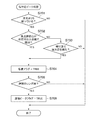
ここで、図7を参照して、ステップS317での端付近ピーク判定処理の詳細について説明する。図7は、図3のステップS317における端付近ピーク判定処理の詳細を説明するフローチャート図である。 Here, the details of the near-end peak determination processing in step S317 will be described with reference to FIG. FIG. 7 is a flowchart for explaining the details of the near-end peak determination process in step S317 in FIG.
図7において、ステップS701では、システム制御部113は、現在の絞りの状態が予め設定している所定の絞り値よりも絞っているか否かを判定し、絞っている場合は、ステップS702に進み、そうでなければ、処理を終了する。ここで予め設定する所定の絞り値は、例えば被写体合焦位置がレンズ端付近に位置する場合に、焦点評価値ピークを検出するのが困難となる絞り値とする。
In FIG. 7, in step S701, the
ステップS702では、システム制御部113は、焦点評価値が今回取得している焦点評価値を含めて所定回以上連続で増加しているか否かを判定し、増加している場合は、ステップS704に進み、そうでなければ、ステップS703に進む。ステップS703では、システム制御部113は、フォーカスレンズ端付近で焦点評価値の極大値を検出したか否かを判定し、検出した場合は、ステップS704に進み、そうでなければ、処理を終了する。
In step S702, the
ステップS704では、システム制御部113は、低速フラグをTRUEに設定し、ステップS705に進む。ここで低速フラグは、レンズ端付近で小絞り時に焦点評価値ピーク形状が緩やかな曲線となっても焦点評価値ピーク位置を検出できるようにフォーカスレンズの駆動速度を遅くするかどうかを判断するためのフラグである。ステップS705では、システム制御部113は、到達したレンズ端が無限遠側のレンズ端か否かを判定する無限遠側レンズ端判定処理を行い、無限遠側のレンズ端であれば、ステップS706の進み、そうでなければ、処理を終了する。
In step S704, the
ステップS706では、システム制御部113は、遠端ピークフラグをTRUEに設定し、処理を終了する。ここで遠端ピークフラグは、無限遠側のフォーカスレンズ端付近に被写体合焦位置があることを判断する合焦位置判断を行うためのフラグである。このフラグは、小絞り時にフォーカスレンズの可動範囲内の全てでAFスキャンを行っても、図3のステップS307における焦点評価値ピーク判定結果がOKとならない場合に、レンズ端付近の被写体合焦位置に合焦制御するために用いる。
In step S706, the
図3に戻って、ステップS318では、システム制御部113は、フォーカスレンズ104の移動方向を反転し、ステップS305に戻る。ステップS319では、システム制御部113は、焦点評価値記憶処理を行い、ステップS320に進む。
Returning to FIG. 3, in step S318, the
ここで、図8を参照して、ステップS319での焦点評価値記憶処理の詳細について説明する。図8は、図3のステップS319における焦点評価値記憶処理の詳細を説明するフローチャート図である。 Here, the details of the focus evaluation value storage process in step S319 will be described with reference to FIG. FIG. 8 is a flowchart for explaining the details of the focus evaluation value storage process in step S319 in FIG.
図8において、ステップS801では、システム制御部113は、低速フラグがTRUEか否かを判定し、TRUEであれば、ステップS802に進み、TRUEでなければ、ステップS807に進む。ステップS802では、低速スキャンCntをインクリメントしてステップS803に進む。ここで低速スキャンCntは、フォーカスレンズ104の駆動速度を遅くした状態で焦点評価値をサンプリングした回数を示しており、レンズ端付近でのみフォーカスレンズ104の駆動速度を遅くするために用いる。
In FIG. 8, in step S801, the
ステップS803では、システム制御部113は、遠端ピークフラグがTRUEか否かを判定し、TRUEであれば、ステップS804に進み、TRUEでなければ、ステップS807に進む。ステップS804では、システム制御部113は、現在の焦点評価値が記憶手段に記憶してある遠端ピーク評価値以上か否かを判定し、遠端ピーク評価値以上であれば、ステップS805に進み、遠端ピーク評価値未満であれば、ステップS807に進む。
In step S803, the
ここでの遠端ピーク評価値は、小絞り時にレンズ端付近でフォーカスレンズ104の移動速度を遅くしている間での焦点評価値の最大値を示しており、その時のフォーカスレンズ104の位置も遠端ピークレンズ位置として記憶手段に記憶されている。この遠端ピーク評価値は、小絞り時にフォーカスレンズ104の可動範囲内の全てでAFスキャンを行っても、図3のステップS307の焦点評価値ピーク判定結果がOKとならない場合に、レンズ端付近の被写体合焦位置に合焦制御するために用いる。
The far-end peak evaluation value here indicates the maximum value of the focus evaluation value while slowing the moving speed of the
ステップS805では、システム制御部113は、遠端ピーク評価値を今回の焦点評価値としてステップS806へ進む。ステップS806では、システム制御部113は、ステップS602での遠端ピークレンズ位置を今回取得したレンズ位置としてステップS807に進む。
In step S805, the
ステップS807では、システム制御部113は、低速フラグがTRUEで、かつ低スキャンCntが予め定めてある所定値以上か否かを判定する。そして、システム制御部113は、低速フラグがTRUEで、かつ低スキャンCntが所定値以上であれば、ステップS808に進み、そうでなければ、処理を終了する。
In step S 807, the
ステップS808では、システム制御部113は、低速フラグをFALSEにしてステップS809に進む。ステップS809では、システム制御部113は、低速スキャンCntを0にして処理を終了する。
In step S808, the
図3に戻って、ステップS320では、システム制御部113は、レンズ速度設定を行い、ステップS321に進む。
Returning to FIG. 3, in step S320, the
ここで、図9を参照して、ステップS320でのレンズ速度設定処理の詳細について説明する。図9は、図3のステップS320におけるレンズ速度設定処理の詳細を説明するフローチャート図である。 Here, the details of the lens speed setting process in step S320 will be described with reference to FIG. FIG. 9 is a flow chart for explaining the details of the lens speed setting process in step S320 in FIG.
図9において、ステップS901では、システム制御部113は、低速フラグがTRUEか否かを判定し、TRUEであれば、ステップS902に進み、TRUEでなければ、ステップS903に進む。低速フラグがTRUEの場合は、ステップS317及びステップS318の処理で、フォーカスレンズ104の移動方向が反転されている。ステップS902では、システム制御部113は、フォーカスレンズ104の移動速度を焦点評価値の所定のサンプリング数又はフォーカスレンズ104の所定の移動範囲のみ反転前の通常速度より低速に設定して処理を終了する。ステップS903では、システム制御部113は、フォーカスレンズ104の移動速度を通常速度に設定して処理を終了する。
In FIG. 9, in step S901, the
これにより、小絞り時においてレンズ端付近に被写体合焦位置が存在した場合に、レンズ端付近のみフォーカスレンズ104の移動速度を低速にすることで、その後のAF時間が長くなってしまうのを防ぐことができる。
In this way, when the subject focusing position exists near the lens end at the time of the small aperture, the moving speed of the
図3に戻って、ステップS321では、システム制御部113は、ステップS320で設定したレンズ速度でフォーカスレンズ104を移動させ、ステップS305に戻る。ステップS305からステップS318、又はステップS305からステップS321までの一連の処理は、現在のフレームレートの1フレーム分の時間で行われるようにする。
Returning to FIG. 3, in step S321, the
以上説明したように、本実施形態では、フォーカスレンズ104の可動範囲が制限される比較的小型のデジタルカメラであっても、小絞り状態での被写体の合焦精度の高精度化を実現することができる。
As described above, in the present embodiment, even in a relatively small digital camera in which the movable range of the
なお、本発明は、上記実施形態に例示したものに限定されるものではなく、本発明の要旨を逸脱しない範囲において適宜変更可能である。 The present invention is not limited to the ones exemplified in the above embodiments, and can be appropriately modified without departing from the scope of the present invention.
例えば、図9のステップS902での低速制御において、所定サンプリング数、または所定のレンズ移動範囲を絞りの絞り値又はフォーカスレンズ104の可動範囲に応じて変更してもよい。また、フォーカスレンズ104の移動速度をフォーカスレンズ104の可動範囲に応じて変更してもよい。
For example, in the low speed control in step S902 in FIG. 9, the predetermined sampling number or the predetermined lens movement range may be changed according to the diaphragm stop value of the diaphragm or the movable range of the
また、本発明は、以下の処理を実行することによっても実現される。即ち、上述した実施形態の機能を実現するソフトウェア(プログラム)を、ネットワーク又は各種記憶媒体を介してシステム或いは装置に供給し、そのシステム或いは装置のコンピュータ(またはCPUやMPU等)がプログラムを読み出して実行する処理である。ネットワーク又は各種記憶媒体を介して取得したソフトウェア(プログラム)をパーソナルコンピュータ(CPU,プロセッサ)にて実行することでも実現できる。 The present invention is also realized by executing the following processing. That is, software (program) for realizing the functions of the above-described embodiments is supplied to a system or apparatus via a network or various storage media, and a computer (or CPU, MPU or the like) of the system or apparatus reads the program. It is a process to execute. It can also be realized by executing software (program) acquired via a network or various storage media on a personal computer (CPU, processor).
101 撮影レンズ
102 絞り/シャッタ
103 AE処理部
104 フォーカスレンズ
105 モータ
106 AF処理部
112 画像記録部
113 システム制御部
101
Claims (9)
絞りの駆動およびフォーカスレンズの移動を制御する制御手段と、を備え、
前記制御手段は、
前記フォーカスレンズが可動範囲の両端のいずれかに到達した場合、前記絞りを所定の絞り値よりも絞っているか否かと、前記到達したレンズ端付近における前記焦点評価値の取得結果に応じて前記フォーカスレンズのレンズ端に向かって前記焦点評価値の増加が続いているか否か、および前記焦点評価値の極大値が検出されたか否かの少なくともいずれか1つと、を判定し、
前記絞りを所定の絞り値よりも絞っている状態で前記焦点評価値の増加が続いている、もしくは前記焦点評価値の極大値が検出されたと判定された場合に、前記フォーカスレンズの移動方向を反転した後の前記焦点評価値の取得の際の前記フォーカスレンズの移動速度を反転前の移動速度よりも遅くし、
前記焦点評価値の増加が続いている、もしくは前記焦点評価値の極大値が検出されたと判定された場合であっても前記絞りを所定の絞り値よりも絞っていない場合には、前記フォーカスレンズの移動方向を反転した後の前記焦点評価値の取得の際の前記フォーカスレンズの移動速度を変更しないことを特徴とする撮像装置。 Acquisition means for acquiring a focus evaluation value based on an output signal from the imaging device;
Control means for controlling the drive of the aperture and the movement of the focus lens;
The control means
If the focus lens has reached one of the ends of the movable range, and whether the aperture is narrowed than the predetermined aperture value, the in response to the acquisition result of the focus evaluation value in the vicinity of the lens edge that the arrival It is determined whether or not the focus evaluation value continues to increase toward the lens end of the focus lens, and / or whether a maximum value of the focus evaluation value is detected.
When it is determined that the focus evaluation value continues to increase while the stop is narrowed more than a predetermined stop value, or it is determined that the maximum value of the focus evaluation value is detected , the moving direction of the focus lens is Making the moving speed of the focus lens at the time of obtaining the focus evaluation value after inversion slower than the moving speed before inversion;
Even if it is determined that the focus evaluation value continues to increase or the local maximum value of the focus evaluation value is detected, the focus lens is not narrowed more than the predetermined aperture value. An imaging apparatus characterized by not changing the moving speed of the focus lens at the time of acquiring the focus evaluation value after reversing the moving direction of the image pickup apparatus.
フォーカスレンズの移動制御において前記撮像素子の出力信号をサンプリングして焦点評価値を取得する、
ことを特徴とする請求項1記載の撮像装置。 The control means
A focus evaluation value is acquired by sampling an output signal of the image pickup element in movement control of a focus lens.
The image pickup apparatus according to claim 1,
前記所定の絞り値は、被写体が合焦する位置がレンズ端付近に位置する場合には焦点評価値のピークを検出するのが困難となる絞り値として予め定められた値である、
ことを特徴とする請求項1または2記載の撮像装置。 The control means
The predetermined aperture value is a value predetermined as an aperture value that makes it difficult to detect the peak of the focus evaluation value when the position where the subject is in focus is located near the lens end.
The imaging device according to claim 1 or 2, characterized in that:
前記制御手段は、前記フォーカスレンズの移動方向を反転した後に、前記焦点評価値のピークが存在しない場合に、前記記憶手段によって記憶されている前記フォーカスレンズの位置を合焦位置として前記フォーカスレンズの移動を制御することを特徴とする請求項1乃至6のいずれか1項に記載の撮像装置。 The apparatus further comprises storage means for storing the maximum value of the focus evaluation value near the lens end and the position of the focus lens corresponding to the maximum value after the moving direction of the focus lens is inverted,
When the peak of the focus evaluation value does not exist after reversing the moving direction of the focus lens, the control means sets the position of the focus lens stored by the storage means as the in-focus position. The imaging apparatus according to any one of claims 1 to 6, wherein movement is controlled.
絞りの駆動およびフォーカスレンズの移動を制御する制御ステップとを備え、
前記制御ステップでは、
前記フォーカスレンズが可動範囲の両端のいずれかに到達した場合、前記絞りを所定の絞り値よりも絞っているか否かと、前記到達したレンズ端付近における前記焦点評価値の取得結果に応じて前記フォーカスレンズのレンズ端に向かって前記焦点評価値の増加が続いているか否か、および前記焦点評価値の極大値が検出されたか否かの少なくともいずれか1つと、を判定し、
前記絞りを所定の絞り値よりも絞っている状態で前記焦点評価値の増加が続いている、もしくは前記焦点評価値の極大値が検出されたと判定された場合に、前記フォーカスレンズの移動方向を反転した後の前記焦点評価値の取得の際の前記フォーカスレンズの移動速度を反転前の移動速度よりも遅くし、
前記焦点評価値の増加が続いている、もしくは前記焦点評価値の極大値が検出されたと判定される場合であっても前記絞りを所定の絞り値よりも絞っていない場合には、前記フォーカスレンズの移動方向を反転した後の前記焦点評価値の取得の際の前記フォーカスレンズの移動速度を変更しない
ことを特徴とする撮像装置の制御方法。 An acquisition step of acquiring a focus evaluation value based on an output signal from the imaging element;
Control step of controlling the movement of the diaphragm drive and the focus lens,
In the control step:
If the focus lens has reached one of the ends of the movable range, and whether the aperture is narrowed than the predetermined aperture value, the in response to the acquisition result of the focus evaluation value in the vicinity of the lens edge that the arrival It is determined whether or not the focus evaluation value continues to increase toward the lens end of the focus lens, and / or whether a maximum value of the focus evaluation value is detected.
When it is determined that the focus evaluation value continues to increase while the stop is narrowed more than a predetermined stop value, or it is determined that the maximum value of the focus evaluation value is detected , the moving direction of the focus lens is Making the moving speed of the focus lens at the time of obtaining the focus evaluation value after inversion slower than the moving speed before inversion;
Even if it is determined that the focus evaluation value continues to increase or the local maximum value of the focus evaluation value is detected, the focus lens is not narrowed down to a predetermined aperture value. A control method of an image pickup apparatus, wherein a moving speed of the focus lens at the time of obtaining the focus evaluation value after reversing a moving direction of the lens is not changed .
Priority Applications (1)
| Application Number | Priority Date | Filing Date | Title |
|---|---|---|---|
| JP2015018305A JP6521649B2 (en) | 2015-02-02 | 2015-02-02 | Image pickup apparatus, control method thereof and program |
Applications Claiming Priority (1)
| Application Number | Priority Date | Filing Date | Title |
|---|---|---|---|
| JP2015018305A JP6521649B2 (en) | 2015-02-02 | 2015-02-02 | Image pickup apparatus, control method thereof and program |
Publications (3)
| Publication Number | Publication Date |
|---|---|
| JP2016142896A JP2016142896A (en) | 2016-08-08 |
| JP2016142896A5 JP2016142896A5 (en) | 2018-03-15 |
| JP6521649B2 true JP6521649B2 (en) | 2019-05-29 |
Family
ID=56570305
Family Applications (1)
| Application Number | Title | Priority Date | Filing Date |
|---|---|---|---|
| JP2015018305A Active JP6521649B2 (en) | 2015-02-02 | 2015-02-02 | Image pickup apparatus, control method thereof and program |
Country Status (1)
| Country | Link |
|---|---|
| JP (1) | JP6521649B2 (en) |
Families Citing this family (1)
| Publication number | Priority date | Publication date | Assignee | Title |
|---|---|---|---|---|
| CN114422690B (en) * | 2021-12-16 | 2022-12-20 | 北京波谱华光科技有限公司 | Control method and device for automatic focusing, electronic equipment and storage medium |
Family Cites Families (5)
| Publication number | Priority date | Publication date | Assignee | Title |
|---|---|---|---|---|
| JPS62269913A (en) * | 1987-04-24 | 1987-11-24 | Minolta Camera Co Ltd | Automatic focusing device |
| JPS62269940A (en) * | 1987-05-08 | 1987-11-24 | Minolta Camera Co Ltd | Automatic focus adjusting device |
| JP2002090618A (en) * | 2000-09-14 | 2002-03-27 | Kyocera Corp | Af system |
| JP2004077959A (en) * | 2002-08-21 | 2004-03-11 | Nikon Corp | Focus adjusting method and camera |
| JP4956093B2 (en) * | 2006-08-25 | 2012-06-20 | キヤノン株式会社 | Focus adjustment device, imaging device, and control method |
-
2015
- 2015-02-02 JP JP2015018305A patent/JP6521649B2/en active Active
Also Published As
| Publication number | Publication date |
|---|---|
| JP2016142896A (en) | 2016-08-08 |
Similar Documents
| Publication | Publication Date | Title |
|---|---|---|
| JP4429328B2 (en) | Automatic focusing device, control method therefor, and imaging device | |
| US9635280B2 (en) | Image pickup apparatus, method of controlling image pickup apparatus, and non-transitory computer-readable storage medium | |
| JP5213813B2 (en) | IMAGING DEVICE AND IMAGING DEVICE CONTROL METHOD | |
| JP5641836B2 (en) | Automatic focusing device, imaging device, focusing control method and program | |
| JP2011248159A (en) | Imaging apparatus, imaging system, imaging apparatus control method and program | |
| JP2012060371A (en) | Imaging system and pixel signal reading method | |
| JP5030308B2 (en) | Automatic focusing device, control method therefor, and imaging device | |
| JP6234016B2 (en) | Focus adjustment device, imaging device, and control method thereof | |
| JP6300550B2 (en) | Automatic focusing device and automatic focusing method | |
| JP6521649B2 (en) | Image pickup apparatus, control method thereof and program | |
| JP6799711B2 (en) | Imaging device, imaging method, and program | |
| JP2016057463A (en) | Focus adjustment device and control method of the same | |
| JP5257969B2 (en) | Focus position control device, focus position control method, focus position control program | |
| US9282234B2 (en) | Focus adjustment apparatus and method, and image capturing apparatus | |
| JP6624789B2 (en) | Focus control device, control method thereof, control program, and imaging device | |
| JP2019032370A (en) | Imaging device and control method thereof | |
| CN113542586A (en) | Image pickup apparatus, control method of image pickup apparatus, and storage medium | |
| JP5904781B2 (en) | Automatic focus adjustment device, control method thereof, and program | |
| JP2006157604A (en) | Camera apparatus and automatic photographing control program | |
| JP6387080B2 (en) | Focus adjustment device, imaging device, and control method of focus adjustment device | |
| JPWO2019064759A1 (en) | Imaging device, imaging method, and program | |
| JP5907610B2 (en) | Optical equipment | |
| JP4574726B2 (en) | Imaging apparatus and automatic focusing control method | |
| JP2014021262A (en) | Focus adjustment device, imaging apparatus, and control method of focus adjustment device | |
| JP2018054815A (en) | Region discrimination device, control method therefor, and control program, and imaging apparatus |
Legal Events
| Date | Code | Title | Description |
|---|---|---|---|
| A521 | Request for written amendment filed |
Free format text: JAPANESE INTERMEDIATE CODE: A523 Effective date: 20180201 |
|
| A621 | Written request for application examination |
Free format text: JAPANESE INTERMEDIATE CODE: A621 Effective date: 20180201 |
|
| A977 | Report on retrieval |
Free format text: JAPANESE INTERMEDIATE CODE: A971007 Effective date: 20180810 |
|
| A131 | Notification of reasons for refusal |
Free format text: JAPANESE INTERMEDIATE CODE: A131 Effective date: 20180821 |
|
| A521 | Request for written amendment filed |
Free format text: JAPANESE INTERMEDIATE CODE: A523 Effective date: 20181022 |
|
| TRDD | Decision of grant or rejection written | ||
| A01 | Written decision to grant a patent or to grant a registration (utility model) |
Free format text: JAPANESE INTERMEDIATE CODE: A01 Effective date: 20190326 |
|
| A61 | First payment of annual fees (during grant procedure) |
Free format text: JAPANESE INTERMEDIATE CODE: A61 Effective date: 20190423 |
|
| R151 | Written notification of patent or utility model registration |
Ref document number: 6521649 Country of ref document: JP Free format text: JAPANESE INTERMEDIATE CODE: R151 |