JP6518736B2 - Gaming machine - Google Patents
Gaming machine Download PDFInfo
- Publication number
- JP6518736B2 JP6518736B2 JP2017160097A JP2017160097A JP6518736B2 JP 6518736 B2 JP6518736 B2 JP 6518736B2 JP 2017160097 A JP2017160097 A JP 2017160097A JP 2017160097 A JP2017160097 A JP 2017160097A JP 6518736 B2 JP6518736 B2 JP 6518736B2
- Authority
- JP
- Japan
- Prior art keywords
- shutter
- slider
- plate
- shutter member
- reel
- Prior art date
- Legal status (The legal status is an assumption and is not a legal conclusion. Google has not performed a legal analysis and makes no representation as to the accuracy of the status listed.)
- Expired - Fee Related
Links
Images


Landscapes
- Slot Machines And Peripheral Devices (AREA)
Description
本発明は、パチスロ等の遊技機に関する。 The present invention relates to a gaming machine such as a pachislot machine.
従来、複数の図柄がそれぞれの表面に配された複数のリールと、遊技メダルやコイン等(以下、「メダル等」という)が投入され、遊技者によりスタートレバーが操作されたことを検出し、複数のリールの回転の開始を要求するスタートスイッチと、複数のリールのそれぞれに対応して設けられたストップボタンが遊技者により押されたことを検出し、該当するリールの回転の停止を要求する信号を出力するストップスイッチと、複数のリールのそれぞれに対応して設けられ、それぞれの駆動力を各リールに伝達するステッピングモータと、スタートスイッチ及びストップスイッチにより出力された信号に基づいて、ステッピングモータの動作を制御し、各リールの回転及びその停止を行うリール制御部とを備え、スタートレバーが操作されたことを検出すると、乱数値に基づいて抽籤を行い、この抽籤の結果(以下、「内部当籤役」という)とストップボタンが操作されたことを検出したタイミングとに基づいてリールの回転の停止を行う、いわゆるパチスロと称される遊技機が知られている。 Conventionally, it is detected that a player operates a start lever by inserting a plurality of reels on which a plurality of symbols are arranged on each surface, game medals, coins and the like (hereinafter referred to as "medals and the like"), It detects that the player has pressed the start switch requesting the start of rotation of the plurality of reels and the stop button provided corresponding to each of the plurality of reels, and requests to stop the rotation of the corresponding reel A stepping motor for outputting a signal, a stepping motor provided corresponding to each of a plurality of reels and transmitting the respective driving force to each reel, and a stepping motor based on a signal outputted by the start switch and the stop switch Control of the movement of the reels and a reel control unit for rotating and stopping each reel, and the start lever is operated. When it is detected, the lottery is performed based on the random number value, and the rotation of the reel is stopped based on the result of this lottery (hereinafter referred to as "internal winning combination") and the timing when the stop button is detected to be operated. A so-called pachislot gaming machine is known.
この種の遊技機として、リール表示窓の上部に配置された液晶表示装置を用いて、内部当籤した小役を入賞させるための各リールの停止操作順序を報知したり、遊技の進行に応じた画像を表示させる等の画像による演出を行うものが知られている(例えば、特許文献1参照)。 As a game machine of this kind, using a liquid crystal display device arranged above the reel display window, the notification of the stop operation order of each reel for winning a small winning combination internally won is made or according to the progress of the game It is known to perform effects by an image such as displaying an image (see, for example, Patent Document 1).
しかしながら、特許文献1に記載の遊技機における視覚的な演出は、画像データの信号処理によって液晶表示装置に表示される画像を切り替えるだけで、特段真新しいものでもなく、また意外性にも欠けるものであった。 However, the visual effects in the gaming machine described in Patent Document 1 are not particularly new ones, except for switching the image displayed on the liquid crystal display device by signal processing of image data, and also lacking in unexpectedness. there were.
本発明は、上述のような事情に鑑みてなされたもので、意外性に富んだ視覚的な演出を行うことで遊技の興趣を向上させることができる遊技機を提供することを目的とする。 The present invention has been made in view of the above-described circumstances, and it is an object of the present invention to provide a gaming machine capable of improving the interest of a game by performing visual effects rich in surprise.
本発明に係る遊技機は、上記目的達成のため、複数枚(例えば、4枚)の板状部材(シャッタ部材201,202,203,204)と、前記板状部材の表面(201a,202a,203a,204a)のなす角度が変更されるよう、前記板状部材を回転可能に支持する支持手段(スライダ機構210)と、前記板状部材に係合する係合部材(234)を有する回転機構(230)と、を備え、前記係合部材は、ギヤ部(234b)が一体形成された回転体で構成され、前記回転機構は、前記係合部材を回転駆動するピニオンギヤ(232)を有する駆動部(駆動モータ231)と、前記ピニオンギヤに噛み合う第1のギヤ部(233b)、及び、前記回転体のギヤ部に噛み合うとともに、前記ピニオンギヤの回転による前記第1のギヤ部の移動に連動して移動する第2のギヤ部(233c)とを有するラック部(233)を備え、前記板状部材は、前記板状部材の一面が遊技機の前後方向に直交する面に対して平行となったとき、上方に位置する一方端部(301)と、下方に位置する他方端部(302)とを有し、前記一方端部及び前記他方端部は、前記板状部材の回転軸方向に直交する方向の断面形状が、前記板状部材の平面に直交する方向に互いに離隔した頂点(301a,302a)を有する形状であり、前記板状部材は、昇降手段(昇降ユニット206)によって第1の位置(図19に示す位置)と前記第1の位置よりも上方に設けられた第2の位置(図17に示す位置)との間で昇降可能に構成され、前記係合部材は、前記板状部材が前記第1の位置に下降した際に前記板状部材に係合するよう構成されている。
The game machine according to the present invention has a plurality of (for example, four) plate-like members (
この構成により、本発明に係る遊技機は、意外性に富んだ視覚的な演出を行うことで遊技の興趣を向上させることができる。 With this configuration, the gaming machine according to the present invention can improve the interest of the game by performing visual effects rich in surprise.
また、板状部材は、回転機構の駆動部によって係合部材が回転駆動されることで回転させられる。このため、板状部材によって単に後方を遮蔽するだけでなく、板状部材の表面と裏面とを反転させることによって板状部材の動きに意外性を持たせることができる。 In addition, the plate-like member is rotated by rotationally driving the engagement member by the drive portion of the rotation mechanism. Therefore, the movement of the plate-like member can be made unexpected by reversing the front and back of the plate-like member as well as simply shielding the rear by the plate-like member.
また、本発明に係る遊技機は、板状部材の一方端部及び他方端部の断面形状が、板状部材の平面に直交する方向に互いに離隔した頂点を有する形状である。このため、例えば板状部材を上昇させる際は、下方の板状部材の一方端部が上方の板状部材の他方端部に接触することにより上方の板状部材を容易に回転させることができる。また、本発明に係る遊技機は、下方の板状部材の一方端部が上方の板状部材の他方端部に接触することにより上方の板状部材を容易に回転させつつ、板状部材を上昇させることができる。 Further, in the gaming machine according to the present invention, the cross-sectional shapes of the one end and the other end of the plate-like member have a shape having apexes separated from each other in the direction orthogonal to the plane of the plate-like member. Therefore, for example, when raising the plate-like member, the upper plate-like member can be easily rotated by one end of the lower plate-like member contacting the other end of the upper plate-like member. . Further, in the gaming machine according to the present invention, the plate-shaped member is easily rotated while one end of the lower plate-shaped member contacts the other end of the upper plate-shaped member while the plate-shaped member is easily rotated. It can be raised.
また、本発明に係る遊技機において、前記一方端部の前記断面形状は、前記板状部材のいずれか一方の面から前記頂点に向けて傾斜した第1の傾斜部(301b)を有する形状であり、前記他方端部の前記断面形状は、前記板状部材のいずれか他方の面から前記頂点に向けて傾斜した第2の傾斜部(302b)を有する形状であり、前記板状部材の回転軸方向に直交する方向の断面形状において、前記板状部材のいずれか一方の面に対して前記第1の傾斜部が占める割合が、前記板状部材のいずれか他方の面に対して前記第2の傾斜部が占める割合よりも大きい構成を有する。 Further, in the gaming machine according to the present invention, the cross-sectional shape of the one end portion is a shape having a first inclined portion (301b) which is inclined from any one surface of the plate-like member toward the apex. And the cross-sectional shape of the other end portion is a shape having a second inclined portion (302b) inclined from any other surface of the plate-like member toward the apex, and the plate-like member is rotated In the cross-sectional shape in the direction orthogonal to the axial direction, the ratio of the ratio of the first inclined portion to one of the surfaces of the plate-like member is the ratio of the ratio to the other surface of the plate-like member. It has a configuration that is larger than the ratio occupied by the two inclined portions.
この構成により、本発明に係る遊技機は、板状部材の一方端部及び他方端部が互いに離隔した頂点に向けて傾斜した第1の傾斜部及び第2の傾斜部を有するので、下方の板状部材の一方端部の第1の傾斜部と上方の板状部材の他方端部の第2の傾斜部との接触によって上方の板状部材を円滑に回転させることができる。 With this configuration, the gaming machine according to the present invention has the first inclined portion and the second inclined portion which are inclined toward the apex at which one end and the other end of the plate member are separated from each other. The upper plate member can be smoothly rotated by the contact between the first inclined portion at one end of the plate member and the second inclined portion at the other end of the upper plate member.
本発明によれば、意外性に富んだ視覚的な演出を行うことで遊技の興趣を向上させることができる遊技機を提供することができる。 According to the present invention, it is possible to provide a gaming machine capable of improving the interest of the game by performing visual effects rich in surprise.
本発明の一実施の形態を示す遊技機であるパチスロ機について、図1〜図30を参照しながら説明する。はじめに、図1を参照して、遊技機の実施の形態に係る機能フローについて説明する。 A pachislot machine which is a gaming machine showing an embodiment of the present invention will be described with reference to FIGS. First, with reference to FIG. 1, a functional flow according to the embodiment of the gaming machine will be described.
本実施の形態のパチスロ機では、遊技を行うための遊技媒体としてメダルを用いる。なお、遊技媒体としては、メダル以外にも、コイン、遊技球、遊技用のポイントデータ又はトークン等を適用することもできる。 In the pachislot machine of the present embodiment, medals are used as game media for playing a game. In addition to the medals, coins, gaming balls, point data or tokens for gaming may be applied as gaming media.
遊技者によりメダルが投入され、スタートレバーが操作されると、予め定められた数値の範囲(例えば、0〜65535)の乱数から1つの値(以下、乱数値)が抽出される。 When medals are inserted by the player and the start lever is operated, one value (hereinafter, random number value) is extracted from random numbers in a predetermined numerical value range (for example, 0 to 65535).
内部抽籤手段は、抽出された乱数値に基づいて抽籤を行い、内部当籤役を決定する。この内部抽籤手段は、後述する主制御回路が担う。内部当籤役の決定により、後述の入賞判定ラインに沿って表示を行うことを許可する図柄の組合せが決定される。なお、図柄の組合せの種別としては、メダルの払い出し、再遊技の作動、ボーナスの作動等といった特典が遊技者に与えられる「入賞」に係るものと、それ以外のいわゆる「ハズレ」に係るものとが設けられている。 The internal lottery means performs lottery based on the extracted random number value to determine an internal winning combination. The internal lottery means is carried by a main control circuit described later. By the determination of the internal winning combination, a combination of symbols permitting display along the later-described winning determination line is determined. In addition, as a classification of combination of the symbol, it is something which relates to the “prize” to which the player is given a privilege such as payout of medals, operation of replay, activation of bonus, etc. Is provided.
また、スタートレバーが操作されると、複数のリールの回転が行われる。その後、遊技者により所定のリールに対応するストップボタンが押されると、リール停止制御手段は、内部当籤役とストップボタンが押されたタイミングとに基づいて、該当するリールの回転を停止する制御を行う。このリール停止制御手段は、後述する主制御回路が担う。 In addition, when the start lever is operated, rotation of the plurality of reels is performed. Thereafter, when the player presses the stop button corresponding to the predetermined reel, the reel stop control means performs control to stop the rotation of the corresponding reel based on the internal winning combination and the timing when the stop button is pressed. Do. The reel stop control means is carried by a main control circuit described later.
パチスロ機では、基本的に、ストップボタンが押されたときから規定時間(190msec又は75msec)内に、該当するリールの回転を停止する制御が行われる。本実施形態では、この規定時間内にリールの回転に伴って移動する図柄の数を「滑り駒数」と呼ぶ。規定時間が190msecである場合には、滑り駒数の最大数を図柄4コマ分に定め、規定時間が75msecである場合には、滑り駒数の最大数を図柄1コマ分に定める。 In the pachi-slot machine, basically, control is performed to stop the rotation of the corresponding reel within a specified time (190 msec or 75 msec) after the stop button is pressed. In the present embodiment, the number of symbols moving with the rotation of the reel within this prescribed time is referred to as the “number of sliding symbols”. If the prescribed time is 190 msec, the maximum number of sliding symbols is determined to be four symbols, and if the prescribed time is 75 msec, the maximum number of sliding symbols is determined to one symbol.
リール停止制御手段は、入賞に係る図柄の組合せ表示を許可する内部当籤役が決定されているときは、通常、190msec(図柄4コマ分)の規定時間内に、その図柄の組合せが入賞判定ラインに沿って極力表示されるようにリールの回転を停止させる。また、リール停止制御手段は、例えば、第2種特別役物であるチャレンジボーナス(CB)及びCBを連続して作動させるミドルボーナス(MB)の動作時には、1つ以上のリールに対して、規定時間75msec(図柄1コマ分)内に、その図柄の組合せが入賞判定ラインに沿って極力表示されるようにリールの回転を停止させる。さらに、リール停止制御手段は、遊技状態に対応する各種規定時間を利用して、内部当籤役によってその表示が許可されていない図柄の組合せが入賞判定ラインに沿って表示されないようにリールの回転を停止させる。 When an internal winning combination that permits combination display of symbols relating to winning is determined, the reel stop control means normally determines that a combination of symbols has a winning determination line within a prescribed time of 190 msec (for four symbols of symbols). Stop the rotation of the reel so that it is displayed as much as possible. In addition, the reel stop control means specifies, for example, for one or more reels, at the time of operation of a bonus bonus (CB) which is a second kind special character and a middle bonus (MB) for operating CB continuously. The rotation of the reel is stopped so that the combination of the symbols is displayed as much as possible along the winning determination line within a time of 75 msec (for one symbol). Furthermore, the reel stop control means uses various prescribed times corresponding to the game state to rotate the reel so that the combination of symbols whose display is not permitted by the internal winning combination is not displayed along the winning determination line. Stop it.
こうして、複数のリールの回転がすべて停止されると、入賞判定手段は、入賞判定ラインに沿って表示された図柄の組合せが、入賞に係るものであるか否かの判定を行う。この入賞判定手段は、後述する主制御回路が担う。入賞判定手段により入賞に係るものであるとの判定が行われると、メダルの払い出し等の特典が遊技者に与えられる。パチスロ機では、以上のような一連の流れが1回の遊技として行われる。 Thus, when the rotations of the plurality of reels are all stopped, the prize determination means determines whether or not the combination of the symbols displayed along the prize determination line relates to a prize. The winning determination means is carried by a main control circuit described later. When it is determined by the winning determination means that the winning is determined, a bonus such as medal payout is given to the player. In the pachislot machine, the above series of flows are performed as one game.
また、パチスロ機では、前述した一連の流れの中で、液晶表示装置などの画像表示装置により行う映像の表示、各種ランプにより行う光の出力、スピーカにより行う音の出力、シャッタ装置によるシャッタの駆動、あるいはこれらの組合せを利用して様々な演出が行われる。 Further, in the pachislot machine, in the above-described series of flows, display of an image performed by an image display device such as a liquid crystal display device, output of light performed by various lamps, output of sound performed by a speaker, drive of a shutter by a shutter device A variety of renditions can be made using these or a combination of these.
スタートレバーが操作されると、上述した内部当籤役の決定に用いられた乱数値とは別に、演出用の乱数値(以下、演出用乱数値)が抽出される。演出用乱数値が抽出されると、演出内容決定手段は、内部当籤役に対応づけられた複数種類の演出内容の中から今回実行するものを抽籤により決定する。この演出内容決定手段は、後述する副制御回路が担う。 When the start lever is operated, a random number for presentation (hereinafter, random number for presentation) is extracted separately from the random number used to determine the internal winning combination described above. When the effect random number value is extracted, the effect content determination means determines by lottery the one to be executed this time out of a plurality of types of effect content associated with the internal winning combination. The effect content determination means is carried by a sub control circuit described later.
演出内容が決定されると、演出実行手段は、リールの回転開始時、各リールの回転停止時、入賞の有無の判定時等の各契機に連動させて対応する演出を実行する。このように、パチスロ機では、内部当籤役に対応づけられた演出内容を実行することによって、決定された内部当籤役(言い換えると、狙うべき図柄の組合せ)を知る機会又は予想する機会が遊技者に提供され、遊技者の興味の向上を図ることができる。 When the contents of the effect are determined, the effect executing means interlocks with respective triggers such as the start of the rotation of the reels, the stop of the rotations of the respective reels, the determination of the presence or absence of winning, etc. to execute the corresponding effects. As described above, in the pachislot machine, the player has an opportunity or opportunity to know the determined internal winning combination (in other words, a combination of the symbols to be aimed) by executing the presentation content corresponding to the internal winning combination. Thus, the player's interest can be improved.
<パチスロ機の構造>
次に、図2を参照して、本実施形態におけるパチスロ機の外観構造について説明する。
<Structure of pachislot machine>
Next, with reference to FIG. 2, an appearance structure of the pachi-slot machine in the present embodiment will be described.
[外観構造]
図2は、パチスロ機1の外部構造を示す斜視図である。
[Appearance structure]
FIG. 2 is a perspective view showing the external structure of the pachi-slot machine 1.
図2に示すように、パチスロ機1は、外装体2を備えている。外装体2は、リールや回路基板等を収容する筐体としてのキャビネット2aと、キャビネット2aに対して開閉自在に取付けられたフロントドア2bとを有している。キャビネット2aの両側面には、把手2cが設けられている(図2では一側面の把手2cのみを示す)。この把手2cは、パチスロ機1を運搬するときに手をかける凹部である。
As shown in FIG. 2, the pachi-slot machine 1 is provided with an
キャビネット2aの内部には、複数(例えば21個)の図柄が周方向に沿って所定の間隔をあけて表示された複数(本実施の形態では3つ)のリール3L,3C,3R(図3参照)が収容されている。
A plurality of (for example, 21 pieces) symbols are displayed inside the
以下、各リール3L,3C,3Rを、それぞれ左リール3L、中リール3C、右リール3Rという。各リール3L,3C,3Rは、円筒状に形成されたリール本体と、リール本体の周面に装着された透光性のシート材を有している。上述の複数(例えば21個)の図柄は、前述のシート材の表面に描かれている。
Hereinafter, the
フロントドア2bは、ドア本体9と、画像を表示する画像表示手段としての液晶表示装置11とを備えている。ドア本体9は、ヒンジ(不図示)を用いてキャビネット2aに開閉自在に取り付けられている。ヒンジは、パチスロ機1の前方からドア本体9を見た場合に、ドア本体9における左側の端部に設けられている。
The
液晶表示装置11は、例えば、遊技上の演出に係る画像や遊技に関する情報を表示するようフロントドア2bのドア本体9の上部に取り付けられている。液晶表示装置11は、映像の表示による演出を実行する他、例えば遊技機のカスタマイズや遊技履歴等の遊技台情報を表示することができる。
The liquid
また、フロントドア2bは、3つのリール3L,3C,3Rを視認させることが可能な表示窓4を有する。表示窓4は、3つのリール3L,3C,3Rに対応する3つの左表示窓4L,中表示窓4C,右表示窓4Rによって構成されている。
Moreover, the
これら表示窓4L,4C,4Rは、正面(遊技者側)から見て、3つのリール3L,3C,3Rの配置領域と重畳する位置に設けられ、かつ、3つのリールより手前(遊技者側)に位置するように設けられる。したがって、遊技者は、表示窓4L,4C,4Rを介して、表示窓4の背後に設けられた3つのリール3L,3C,3Rを視認することができる。
The
本実施形態では、表示窓4L,4C,4Rは、その背後に設けられた対応するリールの回転が停止したとき、各リールに描かれた複数種類の図柄のうち、連続して配置された3つの図柄を表示できる大きさに設定されている。すなわち、表示窓4L,4C,4Rの枠内には、リール毎に上段、中段及び下段の各領域が設けられ、各領域に1個の図柄が表示される。そして、本実施形態では、左リール3Lの中段領域、中リール3Cの中段領域、及び、右リール3Rの中段領域を結ぶラインを、入賞か否かの判定を行う入賞判定ラインとして定義する。
In the present embodiment, the
また、上述したリール3L,3C,3R及び液晶表示装置11の前面側には、保護ガラス6が配設されている。これにより、リール3L,3C,3R及び液晶表示装置11を遊技者が直接触れることができないようになっている。
In addition, a
また、ドア本体9の前面側の上部には、保護ガラス6を取り囲むようにして装飾部材7が取り付けられている。装飾部材7は、パチスロ機1の外装の一部を構成するとともに、上部外装部材7a、一対の側部外装部材7b及び下部外装部材7cを含んで構成されている。特に、上部外装部材7aは、液晶表示装置11の上方であって、後述するシャッタ装置200の前方に配置されている。上部外装部材7aは、外装部材を構成する。
Further, a
ドア本体9の中央には、台座部12が形成されている。この台座部12には、遊技者の操作対象となる各種装置(メダル投入口13、MAXベットボタン14、1ベットボタン15、スタートレバー16、ストップボタン17L,17C,17R、選択ボタン18、決定ボタン19)が設けられている。
A
メダル投入口13は、遊技者によって外部からパチスロ機1に投下されるメダルを受け入れるために設けられる。すなわち、メダル投入口13は、遊技者によってメダルが投入されるためのものである。メダル投入口13から投入されたメダルは、予め設定された枚数(例えば3枚)を上限として1回の遊技に使用され、予め設定された枚数を超えた分は、パチスロ機1の内部に預けることができる(いわゆるクレジット機能)。
The
MAXベットボタン14及び1ベットボタン15は、パチスロ機1の内部に預けられているメダルから1回の遊技に使用する枚数を決定するために設けられる。なお、図2には示さないが、台座部12には、精算ボタンが設けられる。この精算ボタンは、パチスロ機1の内部に預けられているメダルを外部に引き出す(排出する)ために設けられる。
The
スタートレバー16は、遊技者の操作に応じて全てのリール(3L,3C,3R)の回転を開始させるためのものであり、開始操作手段を構成する。
The
ストップボタン17L,17C,17Rは、それぞれ、左リール3L、中リール3C、右リール3Rに対応付けて設けられ、遊技者の操作に応じて対応する各リールの回転を停止させるためのものである。これらストップボタン17L,17C,17Rは、停止操作手段を構成する。
The
また、これらストップボタン17L,17C,17Rは、液晶表示装置11に表示される情報に関する操作を行う際に用いられるようになっており、例えば液晶表示装置11の表示画面上における選択操作を行う際に用いられる。以下、ストップボタン17L,17C,17Rを、それぞれ左ストップボタン17L、中ストップボタン17C、右ストップボタン17Rという。
Further, these
選択ボタン18及び決定ボタン19は、液晶表示装置11の表示画面上における各種操作を行う際に用いられる。
The
また、台座部12には、7セグメントLED(Light Emitting Diode)からなる7セグ表示器28が設けられている。この7セグ表示器28は、特典として遊技者に対して払い出すメダルの枚数(以下、払出枚数)、パチスロ機1の内部に預けられているメダルの枚数(以下、クレジット枚数)等の情報をデジタル表示する。
Further, the
ドア本体9の下部には、メダル払出口21、メダル受皿22、スピーカ23L,23R等が設けられている。メダル払出口21は、後述のホッパー装置43の駆動により排出されるメダルを外部に導く。メダル受皿22は、メダル払出口21から排出されたメダルを貯める。また、スピーカ23L,23Rは、演出内容に対応する効果音や楽曲等の音を出力する。
At the lower part of the door main body 9, a
<パチスロ機の電気的構成>
次に、パチスロ機1の電気的構成について、図3を参照して説明する。図3は、パチスロ機1の電気的構成を示すブロック図である。
<Electric configuration of pachislot machine>
Next, the electrical configuration of the pachislot machine 1 will be described with reference to FIG. FIG. 3 is a block diagram showing the electrical configuration of the pachi-slot machine 1.
図3に示すように、パチスロ機1は、キャビネット2aに配設された主制御基板41と、フロントドア2bに配設された副制御基板42とを有している。主制御基板41には、リール中継端子板51と、設定用鍵型スイッチ52と、キャビネット側中継基板53と、ドア中継端子板54と、電源装置44の電源基板44bとが電気的に接続されている。
As shown in FIG. 3, the pachislot machine 1 has a
リール中継端子板51は、各リール3L,3C,3Rのリール本体の内側に配設されている。このリール中継端子板51は、各リール3L,3C,3Rのステッピングモータ(不図示)に電気的に接続されており、主制御基板41からステッピングモータに出力される信号を中継する。設定用鍵型スイッチ52は、パチスロ機1の設定を変更する際又はパチスロ機1の設定を確認する際に使用する。
The reel
キャビネット側中継基板53には、外部集中端子板56と、ホッパー装置43と、メダル補助収納庫スイッチ57とが電気的に接続されている。このキャビネット側中継基板53は、主制御基板41から外部集中端子板56、ホッパー装置43、メダル補助収納庫スイッチ57に出力される信号を中継する。つまり、外部集中端子板56、ホッパー装置43及びメダル補助収納庫スイッチ57は、キャビネット側中継基板53を介して主制御基板41に接続されている。
An external concentrated
外部集中端子板56は、キャビネット2aに取り付けられており、メダル投入信号、メダル払出信号及びセキュリティ信号などの信号をパチスロ機1の外部へ出力するために設けられている。
The external concentrated
メダル補助収納庫スイッチ57は、図示しないメダル補助収納庫を貫通している。このメダル補助収納庫スイッチ57は、メダル補助収納庫がメダルで満杯になっているか否かを検出する。
The medal
電源装置44の電源基板44bには、電源スイッチ44aが接続されている。この電源スイッチ44aは、パチスロ機1に必要な電源を供給するときにONにする。
A
ドア中継端子板54には、メダルセンサ46、ドア開閉監視スイッチ61、BETスイッチ62、精算スイッチ63、スタートスイッチ64、ストップスイッチ基板65、遊技動作表示基板66、選択スイッチ67、決定スイッチ68及び副中継基板69が接続されている。つまり、メダルセンサ46、ドア開閉監視スイッチ61、BETスイッチ62、精算スイッチ63、スタートスイッチ64、ストップスイッチ基板65、遊技動作表示基板66、選択スイッチ67、決定スイッチ68及び副中継基板69は、ドア中継端子板54を介して主制御基板41に接続されている。
In the door
メダルセンサ46は、メダルが図示しないセレクタ内を通過したことを検出して、その検出結果を主制御基板41に出力する。ドア開閉監視スイッチ61は、フロントドア2bの開閉を報知するためのセキュリティ信号をパチスロ1の外部へ出力する。BETスイッチ62は、MAXベットボタン14及び1ベットボタン15(図2参照)が遊技者により押されたことを検出して、その検出結果を主制御基板41に出力する。
The
精算スイッチ63は、精算ボタン(不図示)が遊技者により押されたことを検出して、その検出結果を主制御基板41に出力する。スタートスイッチ64は、スタートレバー16が遊技者により操作されたこと(開始操作)を検出して、その検出結果を主制御基板41に出力する。
The
ストップスイッチ基板65は、回転しているリールを停止させるための回路と、停止可能なリールをLEDなどにより表示するための回路を構成する基板である。このストップスイッチ基板65には、ストップスイッチが設けられている。ストップスイッチは、各ストップボタン17L,17C,17Rが遊技者により押されたこと(停止操作)を検出する。
The
遊技動作表示基板66は、メダルの投入を受け付けるとき、3つのリール3L,3C,3Rが回動可能なとき及び再遊技を行うときに、投入されたメダルの枚数を7セグ表示器28に表示させるための基板である。この遊技動作表示基板66には、7セグ表示器28とLED70が接続されている。LED70は、例えば、遊技の開始を表示するマークや再遊技を行うマークなどを点灯させる。
The game
選択スイッチ67は、選択ボタン18が遊技者により押されたことを検出して、その検出結果を主制御基板41及び副中継基板69に出力する。決定スイッチ68は、決定ボタン19が遊技者により押されたことを検出して、その検出結果を主制御基板41及び副中継基板69に出力する。
The
副中継基板69は、副制御基板42と主制御基板41とを接続する配線を中継する。また、副中継基板69は、副制御基板42と副制御基板42の周辺に配設された複数の基板とを接続する配線を中継する。すなわち、副中継基板69には、副制御基板42と、サウンドI/O基板71と、LED基板72と、24hドア開閉監視ユニット74と、シャッタ制御基板78とが電気的に接続されている。
The
副制御基板42は、ドア中継端子板54と副中継基板69を介して主制御基板41に接続されている。また、副制御基板42は、副中継基板69を介して、サウンドI/O基板71と、LED基板72と、24hドア開閉監視ユニット74と、シャッタ制御基板78とに電気的に接続されている。
The
サウンドI/O基板71は、スピーカ23L,23Rへの音声の出力を行う。LED基板72は、副制御回路101(図5参照)の制御により実行される演出に応じて、光源の一具体例を示すLED群25を発光させて、点滅パターンを表示する。
The sound I /
24hドア開閉監視ユニット74は、フロントドア2bの開閉の履歴を保存する。また、24hドア開閉監視ユニット74は、フロントドア2bを開放したときに、液晶表示装置11にエラー表示を行うための信号を副制御基板42(副制御回路101)に出力する。
The 24h door opening and
シャッタ制御基板78は、副制御回路101(図5参照)の制御により実行される演出に応じて、シャッタ装置200を駆動させる。シャッタ装置200は、シャッタ制御基板78によって駆動制御されることで後述するシャッタ部材201,202,203,204の昇降を行う。
The
副制御基板42には、ロムカートリッジ基板76と、液晶中継基板77とが接続されている。ロムカートリッジ基板76は、演出用の画像(映像)、音声、光(LED群25)、シャッタ装置200の駆動及び通信のデータを管理するための基板である。液晶中継基板77は、副制御基板42と液晶表示装置11とを接続する配線を中継する基板である。
A
<主制御回路>
次に、主制御基板41により構成される主制御回路91について、図4を参照して説明する。図4は、パチスロ機1の主制御回路91の構成例を示すブロック図である。
<Main control circuit>
Next, the
図4に示すように、主制御部としての主制御回路91は、主制御基板41上に設置されたマイクロコンピュータ92を主たる構成要素とし、遊技の進行を制御するものである。マイクロコンピュータ92は、メインCPU93、メインROM94及びメインRAM95により構成される。
As shown in FIG. 4, the
メインROM94には、メインCPU93により実行される制御プログラム、データテーブル、副制御回路101に対して各種制御指令(コマンド信号)を送信するためのデータ等が記憶されている。メインRAM95には、制御プログラムの実行により決定された内部当籤役等の各種データを格納する格納領域が設けられる。
The
メインCPU93には、クロックパルス発生回路96、分周器97、乱数発生器98及びサンプリング回路99が接続されている。クロックパルス発生回路96及び分周器97は、クロックパルスを発生する。メインCPU93は、発生されたクロックパルスに基づいて、制御プログラムを実行する。乱数発生器98は、予め定められた範囲の乱数(例えば、0〜65535)を発生する。サンプリング回路99は、発生された乱数の中から1つの値を抽出する。
To the
メインCPU93は、リールインデックスを検出してから各リール3L,3C,3Rのステッピングモータに対してパルスを出力した回数をカウントする。これにより、メインCPU93は、各リール3L,3C,3Rの回転角度(主に、リールが図柄何個分だけ回転したか)を管理する。
The
なお、リールインデックスとは、リールが一回転したことを示す情報である。このリールインデックスは、例えば、発光部及び受光部を有する光センサと、各リール3L,3C,3Rの所定の位置に設けられ、各リール3L,3C,3Rの回転により発光部と受光部との間に介在される検知片を備えたリール位置検出部(不図示)により検出する。
The reel index is information indicating that the reel has made one rotation. The reel index is provided, for example, at a predetermined position of each of the
ここで、各リール3L,3C,3Rの回転角度の管理について、具体的に説明する。ステッピングモータに対して出力されたパルスの数は、メインRAM95に設けられたパルスカウンタによって計数される。そして、図柄1つ分の回転に必要な所定回数(例えば16回)のパルスの出力がパルスカウンタで計数される毎に、メインRAM95に設けられた図柄カウンタが1ずつ加算される。図柄カウンタは、各リール3L,3C,3Rに応じて設けられている。図柄カウンタの値は、リール位置検出部(不図示)によってリールインデックスが検出されるとクリアされる。
Here, management of the rotation angles of the
つまり、本実施の形態では、図柄カウンタを管理することにより、リールインデックスが検出されてから図柄何個分の回転が行われたのかを管理するようになっている。したがって、各リール3L,3C,3Rの各図柄の位置は、リールインデックスが検出される位置を基準として検出される。
That is, in the present embodiment, by managing the symbol counter, it is managed to manage how many symbols have been rotated since the reel index was detected. Therefore, the position of each symbol of each
本実施の形態では、基本的に滑り駒数の最大数を図柄4個分に定めている。したがって、左ストップボタン17Lが押されたときに表示窓4の中段にある左リール3Lの図柄と、その4個先の図柄までの範囲内にある各図柄が、表示窓4の中段に停止可能な図柄となる。
In the present embodiment, basically, the maximum number of sliding symbols is set to four symbols. Therefore, when the
<副制御回路>
次に、副制御基板42により構成される副制御回路101について、図5を参照して説明する。図5は、パチスロ機1の副制御回路101の構成例を示すブロック図である。
<Sub control circuit>
Next, the
図5に示すように、副制御部としての副制御回路101は、主制御回路91と電気的に接続されており、主制御回路91から送信されるコマンド信号に基づいて演出内容の決定や実行等の処理を行うとともに、液晶表示装置11、シャッタ装置200、LED群25、スピーカ23L,23R等の周辺装置の制御を行うものである。副制御回路101は、基本的に、サブCPU102、サブRAM103、レンダリングプロセッサ104、描画用RAM105、ドライバ106を含んで構成されている。
As shown in FIG. 5, the
サブCPU102は、主制御回路91から送信されたコマンド信号に応じて、ロムカートリッジ基板76に記憶されている制御プログラムに従い、映像、音、光の出力及びシャッタ装置200の駆動の制御を行う。ロムカートリッジ基板76は、基本的に、プログラム記憶領域とデータ記憶領域によって構成される。
The
プログラム記憶領域には、サブCPU102が実行する制御プログラムが記憶されている。例えば、制御プログラムには、主制御回路91との通信を制御するための主基板通信タスクや、演出用乱数値を抽出し、演出内容(演出データ)の決定及び登録を行うための演出登録タスクが含まれる。また、決定した演出内容に基づいて液晶表示装置11(図2参照)による映像の表示を制御する描画制御タスク、シャッタ装置200によるシャッタ部材201,202,203,204の昇降や回転を制御する役物制御タスク、LED群25等の光源による光の出力を制御するランプ制御タスク、スピーカ23L,23Rによる音の出力を制御する音声制御タスク等が含まれる。
The program storage area stores a control program to be executed by the
データ記憶領域は、各種データテーブルを記憶する記憶領域、各演出内容を構成する演出データを記憶する記憶領域、映像の作成に関するアニメーションデータを記憶する記憶領域が含まれている。また、BGMや効果音に関するサウンドデータを記憶する記憶領域、光の点消灯のパターンに関するランプデータを記憶する記憶領域等が含まれている。 The data storage area includes a storage area for storing various data tables, a storage area for storing effect data constituting each effect content, and a storage area for storing animation data relating to creation of a video. Also, a storage area for storing sound data relating to BGM and sound effects, a storage area for storing lamp data relating to a light on / off pattern, and the like are included.
サブRAM103は、決定された演出内容や演出データを登録する格納領域や、主制御回路91から送信される内部当籤役等の各種データを格納する格納領域が設けられている。
The
サブCPU102、レンダリングプロセッサ104、描画用RAM(フレームバッファを含む)105及びドライバ106は、演出内容により指定されたアニメーションデータに従って映像を作成し、作成した映像を液晶表示装置11に表示させる。また、サブCPU102は、演出内容により指定された役物可動データに従ってシャッタ装置200を駆動する。
The
また、サブCPU102は、演出内容により指定されたサウンドデータに従ってBGMなどの音をスピーカ23L,23Rにより出力させる。また、サブCPU102は、演出内容により指定されたランプデータに従ってLED群25の点灯及び消灯を制御する。
Further, the
<シャッタ装置>
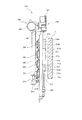
次に、シャッタ装置200について、図6〜図30を参照して説明する。図6〜図14は、シャッタ装置200の構成を示す図であって、シャッタ部材201,202,203,204が1枚ずつ下降していく過程を示したものである。
<Shutter device>
Next, the
図7に示すように、シャッタ装置200は、液晶表示装置11よりもパチスロ機1の前面側に設けられている。なお、図7においては、左側がパチスロ機1の前面側であり、右側がパチスロ機1の背面側である。また、図7では、図示をしていないが、シャッタ装置200の前面側(図中、左側)には、保護ガラス6(図2参照)が配置されている。したがって、シャッタ装置200は、保護ガラス6と液晶表示装置11との間に設けられ、液晶表示装置11よりも遊技者側に配置されている。
As shown in FIG. 7, the
ここで、図6、図9、図11及び図13は、それぞれシャッタ装置200をパチスロ機1の背面側、つまり液晶表示装置11側から見た図である。
Here, FIGS. 6, 9, 11 and 13 are views of the
図6及び図7に示すように、シャッタ装置200は、シャッタベース220と、複数枚(本実施の形態では、4枚)の板状のシャッタ部材201,202,203,204と、昇降手段としての昇降ユニット206と、スライダ機構210と、回転機構230と、を含んで構成されている。なお、シャッタ部材の枚数は、4枚に限らず、2枚又は3枚、もしくは5枚以上であってもよい。
As shown in FIGS. 6 and 7, the
シャッタベース220は、コの字型の板状に成形され、図示しない締結部材を介してフロントドア2bのドア本体9(図2参照)に取り付けられている。また、シャッタベース220は、上片部221と、上片部221の長手方向の両端に一体成形された一対の側片部222,223と、を含んで構成されている。
The
一対の側片部222,223には、それぞれ長手方向(上下方向)に延在する長穴222a,222b,222c、223a,223b,223cが形成されている。長穴222a,223aには、後述する第1のスライダ211及び第2のスライダ212が上下方向に摺動可能に取り付けられている。また、長穴222b,223bには、後述する第3のスライダ213が上下方向に摺動可能に取り付けられている。さらに、長穴222c,223cには、後述する第4のスライダ214が上下方向に摺動可能に取り付けられている。
In the pair of
シャッタ部材201,202,203,204は、液晶表示装置11を遮蔽する遮蔽位置(図19に示す位置)と液晶表示装置11を露出させる露出位置(図17に示す位置)との間で昇降可能に構成されている。ここで、露出位置(図17に示す位置)は、遮蔽位置(図19に示す位置)よりも上方に設けられている。
The
図7に示すように、昇降ユニット206は、昇降モータ240と、テンショナ241と、駆動ベルト242とを含んで構成されている。昇降ユニット206は、図28に示すように、シャッタベース220の一対の側片部222,223にそれぞれ設けられている。
As shown in FIG. 7, the lifting and lowering
昇降モータ240は、正逆回転可能な、例えばステッピングモータによって構成されている。昇降モータ240は、カバー部材250(図28参照)の内部に固定されている。カバー部材250は、昇降ユニット206を覆うようにしてシャッタベース220の一対の側片部222,223にそれぞれ固定されている。
The
また、図8(a)に示すように、昇降モータ240は、図示しない駆動軸を有し、この駆動軸には、ピニオンギヤ240aが取り付けられている。また、カバー部材250(図28参照)の内部には、ギヤ部244aが一体回転可能に設けられた駆動プーリ244が回転自在に支持されている。
Further, as shown in FIG. 8A, the
上述のピニオンギヤ240aは、ギヤ部244aと噛み合うよう構成され、昇降モータ240の回転を駆動プーリ244に伝達するようになっている。駆動プーリ244には、駆動ベルト242が巻き掛けられている。
The above-described
テンショナ241は、カバー部材250(図28参照)の内部に取り付けられ、図示しないスプリングによって常時下方に付勢されるテンションプーリ241aを有している。テンションプーリ241aには、駆動ベルト242が巻き掛けられている。これにより、駆動ベルト242は、常に一定以上の張力に維持される。
The
駆動ベルト242は、駆動プーリ244とテンションプーリ241aとに巻き掛けられ、昇降モータ240によって駆動プーリ244を介して周回駆動するようになっている。また、図8(a)に示すように、駆動ベルト242には、第1のスライダ211が連結されている。
The
これにより、第1のスライダ211は、駆動ベルト242の周回駆動に伴って上下に昇降する。なお、後述するが、第1のスライダ211には、シャッタ部材201,202,203,204のうち、最下位のシャッタ部材201が回転可能に支持されている。
Thus, the
したがって、昇降ユニット206は、シャッタ部材201,202,203,204のうち、最下位のシャッタ部材201を遮蔽位置(図19に示す位置)と露出位置(図17に示す位置)との間で昇降させるものである。
Therefore, the lifting and lowering
図6に示すように、スライダ機構210は、最下位のシャッタ部材201以外の他のシャッタ部材202,203,204を最下位のシャッタ部材201に連動させて、遮蔽位置(図19に示す位置)と露出位置(図17に示す位置)との間で昇降するよう、最下位のシャッタ部材201と他のシャッタ部材202,203,204とを接続するものである。
As shown in FIG. 6, the
具体的には、スライダ機構210は、第1のスライダ211と、第2のスライダ212と、第3のスライダ213と、第4のスライダ214とを含んで構成されている。第1のスライダ211、第2のスライダ212、第3のスライダ213及び第4のスライダ214は、いずれもシャッタ部材201,202,203,204を回転可能に支持している。
Specifically, the
これにより、シャッタ部材201,202,203,204は、それぞれの表面201a,202a,203a,204a(図19において露出している面)と液晶表示装置11の画像表示面11a(図7参照)とのなす角度が変更されるようスライダ機構210に回転可能に支持される。
Thereby, the
第1のスライダ211は、一対の側片部222,223の長穴222a,223aに沿って上下方向に摺動可能となっている。図8(b)に示すように、第1のスライダ211の上端部には、第2のスライダ212に当接可能なように画像表示面側(図8(a)中、右側)に突出したストッパ部211aが形成されている。ストッパ部211aは、後述する第2のスライダ212の上下の当接面212a,212bに当接することで、第2のスライダ212に対する第1のスライダ211の移動範囲を規制するものである。
The
図6に示すように、第2のスライダ212は、第1のスライダ211と同様、一対の側片部222,223の長穴222a,223aに沿って上下方向に摺動可能となっている。
As shown in FIG. 6, the
図8(b)に示すように、第2のスライダ212には、画像表示面側と反対側(図8(a)中、左側)に窪んだ凹部212Aが形成されている。凹部212Aの上下の内壁面には、第1のスライダ211のストッパ部211aが当接可能な当接面212a,212bが形成されている。
As shown in FIG. 8B, the
また、図6に示すように、第2のスライダ212の上端部には、上下方向に直交する左右方向(図6中、左右方向)にそれぞれ突出した内側ストッパ部212c及び外側ストッパ部212dが設けられている。
Further, as shown in FIG. 6, the upper end portion of the
内側ストッパ部212cは、後述する第3のスライダ213の上下の当接面213a,213bに当接することで、第3のスライダ213に対する第2のスライダ212の移動範囲を規制するものである。一方、外側ストッパ部212dは、後述する第4のスライダ214の上下の当接面214a,214bに当接することで、第4のスライダ214に対する第2のスライダ212の移動範囲を規制するものである。
The
第3のスライダ213は、一対の側片部222,223の長穴222b,223bに沿って上下方向に摺動可能となっている。第3のスライダ213には、画像表示面側(図7中、右側)に窪んだ凹部213Aが形成されている。凹部213Aの上下の内壁面には、第2のスライダ212の内側ストッパ部212cが当接可能な当接面213a,213bが形成されている。
The
第4のスライダ214は、一対の側片部222,223の長穴222c,223cに沿って上下方向に摺動可能となっている。第4のスライダ214には、画像表示面側(図7中、右側)に窪んだ凹部214Aが形成されている。凹部214Aの上下の内壁面には、第2のスライダ212の外側ストッパ部212dが当接可能な当接面214a,214bが形成されている。このように構成されたスライダ機構210は、接続手段及び支持手段を構成する。
The
ここで、図6〜図14を参照して、シャッタ部材201,202,203,204を下降させる際の上述したスライダ機構210の動作について説明する。
Here, with reference to FIGS. 6 to 14, the operation of the above-described
まず、図6〜図8に示すように、昇降ユニット206によって露出位置(図17に示す位置)にある最下位のシャッタ部材201を下降させると、他のシャッタ部材202,203,204もその自重により最下位のシャッタ部材201に追従して下降する。
First, as shown in FIGS. 6-8, when the
このとき、まず最初に、第4のスライダ214が長穴222c,223cの最下部に突き当たり、それ以上の下方への移動が規制される。このとき、第2のスライダ212の当接面212aは、第1のスライダ211のストッパ部211aに当接している。また、第2のスライダ212の内側ストッパ部212cは、第3のスライダ213の当接面213aに当接している。
At this time, first, the
次いで、図9及び図10に示すように、第3のスライダ213が長穴222b,223bの最下部に突き当たり、それ以上の下方への移動が規制される。このとき、第2のスライダ212の内側ストッパ部212cは、第3のスライダ213の当接面213aへの当接が解消される。
Then, as shown in FIGS. 9 and 10, the
次いで、図11及び図12に示すように、第2のスライダ212の内側ストッパ部212cが第3のスライダ213の当接面213bに当接し、第2のスライダ212のそれ以上の下方への移動が規制される。このとき、第2のスライダ212の外側ストッパ部212dは、第4のスライダ214の当接面214bに当接することとなる。
Then, as shown in FIGS. 11 and 12, the
最後に、図13及び図14に示すように、第1のスライダ211が長穴222a,223aの最下部に突き当たり、それ以上の下方への移動が規制される。このとき、第1のスライダ211のストッパ部211aは、第2のスライダ212の当接面212bに当接することとなる。これにより、シャッタ部材201,202,203,204が遮蔽位置(図19に示す位置)にて停止することとなる。
Finally, as shown in FIGS. 13 and 14, the
一方、昇降ユニット206によって遮蔽位置(図19に示す位置)にある最下位のシャッタ部材201を上昇させると、まず、第1のスライダ211のストッパ部211aが第2のスライダ212の当接面212aに当接する。
On the other hand, when the
次いで、第2のスライダ212が第1のスライダ211によって押し上げられる。続いて、第1のスライダ211とともに第2のスライダ212が上昇すると、今度は、第2のスライダ212の内側ストッパ部212cが第3のスライダ213の当接面213aに当接する。
Then, the
その後、第3のスライダ213が第2のスライダ212によって押し上げられる。続いて、第1のスライダ211及び第2のスライダ212とともに第3のスライダ213が上昇すると、第2のスライダ212の外側ストッパ部212dが第4のスライダ214の当接面214aに当接する。
Thereafter, the
次いで、第4のスライダ214が第2のスライダ212によって押し上げられる。続いて、第1のスライダ211、第2のスライダ212及び第3のスライダ213とともに第4のスライダ214が上昇すると、第4のスライダ214が長穴223cの最上部に突き当たり、それ以上の上昇が規制される。これにより、シャッタ部材201,202,203,204が露出位置(図17に示す位置)にて停止することとなる。
The
ここで、図17及び図18に示すように、シャッタ部材201,202,203,204は、昇降ユニット206によって露出位置に上昇させられたとき、それぞれの表面201a,202a,203a,204a(図18参照)が上方を向くよう回転した状態で互いに重畳されて上部外装部材7aの背面側の空間に収容される。
Here, as shown in FIGS. 17 and 18, when the
次に、図15及び図16を参照して、スライダ機構210に対するシャッタ部材201,202,203,204の支持構造について、シャッタ部材203を例に説明する。なお、他のシャッタ部材201,202,204については、シャッタ部材203と同様であるため、その説明を省略する。
Next, with reference to FIGS. 15 and 16, the support structure of the
図15(a)、(b)に示すように、シャッタ部材203は、長手方向の両端に回転軸203Aを有しており、この回転軸203Aが第3のスライダ213に回転可能に支持されることで、シャッタ部材203が回転可能となっている。なお、図15及び図16においては、第3のスライダ213の一部形状を省略している。
As shown in FIGS. 15A and 15B, the
また、シャッタ部材203の回転軸203Aの両端には、後述する回転機構230の係合部材234に係合可能な回転体260が一体回転可能に取り付けられている。
Further, at both ends of the
ここで、図15(b)及び図16(b)に示すように、第3のスライダ213には、回転体260側に突出した突出部213cが形成されている。また、回転体260には、回転体260が回転した際に、前述した突出部213cに当接することによって、回転体260の回転範囲を規制する規制部260a,260bが形成されている。なお、本実施の形態における回転体260の回転範囲は、略180°である。これにより、シャッタ部材203は、表面203aと裏面203bとを反転することができる。
Here, as shown in FIGS. 15 (b) and 16 (b), the
さらに、回転体260と第3のスライダ213との間には、いわゆる巻き戻しタイプのねじりばね262が設けられている。ねじりばね262は、一方のフックが第3のスライダ213に係止され、かつ他方のフックが回転体260に係止されており、シャッタ部材203の表面203aが画像表示面11aに対して平行となるよう回転体260を、図15(a)中、矢印Gで示す一の回転方向に常時付勢している。ねじりばね262は、付勢手段を構成する。
Furthermore, a so-called unwinding
本実施の形態では、シャッタ部材203が露出位置(図17に示す位置)にあるときには、図16(a)、(b)に示すように、ねじりばね262の付勢力に抗して回転体260が図16(a)中、矢印Hで示す他の回転方向(図15(a)中、矢印Gで示す一の回転方向と逆回転方向)に回転した状態となる。これにより、シャッタ部材203は、他のシャッタ部材201,202,204とともに折り重なるようにして上部外装部材7a(図18参照)の背面側の空間に収容される。
In the present embodiment, when the
一方、シャッタ部材203が遮蔽位置(図19に示す位置)にあるときには、図15(a)、(b)に示すように、ねじりばね262の付勢力によって回転体260が図15(a)中、矢印Gで示す一の回転方向に回転した状態となる。これにより、シャッタ部材203は、表面203aが画像表示面11aに対して平行な状態となる。
On the other hand, when the
次に、図19〜図26を参照して、回転機構230について説明する。
Next, the
まず、回転機構230は、シャッタ部材201,202,203,204が遮蔽位置にあるときに、シャッタ部材201,202,203,204が図19に示す状態、図23に示す状態、及び図25に示す状態のいずれかの状態となるよう、シャッタ部材201,202,203,204を回転させるものである。
First, in the
ここで、図19に示す状態は、シャッタ部材201,202,203,204の表面201a,202a,203a,204aがパチスロ機1の前面側を向いた状態で、液晶表示装置11を遮蔽した状態である。
Here, in the state shown in FIG. 19, the liquid
図23に示す状態は、シャッタ部材201,202,203,204の表面201a,202a,203a,204aが液晶表示装置11の画像表示面11aに対して直交した角度で停止した状態である。すなわち、図23に示す状態は、シャッタ部材201,202,203,204が半開状態にあり、これらシャッタ部材間の隙間から画像表示面11aが視認可能な状態である。
In the state shown in FIG. 23, the
図25に示す状態は、シャッタ部材201,202,203,204の裏面201b,202b,203b,204bがパチスロ機1の前面側を向いた状態で、液晶表示装置11を遮蔽した状態である。
The state shown in FIG. 25 is a state in which the liquid
図20に示すように、回転機構230は、駆動部としての駆動モータ231(図6参照)と、ラック部233と、係合部材234と、を含んで構成されている。
As shown in FIG. 20, the
図6に示すように、駆動モータ231は、シャッタベース220の側片部222の下方においてベース部材238に取り付けられている。なお、ベース部材238は、図示しない締結部材を介してドア本体9に固定されている。
As shown in FIG. 6, the
駆動モータ231は、回転角度を調整可能かつ正逆回転可能な、例えばステッピングモータによって構成されている。また、駆動モータ231の駆動軸には、図20に示すように、ピニオンギヤ232が一体回転可能に取り付けられている。
The
ラック部233は、ベース部材238(図6参照)に設けられた固定ピン238aが嵌合するスライド穴233aを有している。また、ラック部233には、ピニオンギヤ232に噛み合う第1のギヤ部233bと、後述する係合部材234のギヤ部234b(図21参照)に噛み合う第2のギヤ部233cとが形成されている。
The
これにより、ラック部233は、ピニオンギヤ232の回転に応じて固定ピン238aに沿って上下方向に移動自在となっている。
Thus, the
係合部材234は、シャッタ部材201,202,203,204に対応して4つ設けられている。また、係合部材234は、シャッタ部材201,202,203,204が遮蔽位置(図19に示す位置)に下降した際に、シャッタ部材201,202,203,204の回転体260(図16(a)参照)に係合するようになっている。
Four engaging
具体的には、図21及び図22に示すように、回転体260には、係合部材234に係合可能な係合突起260cが形成されている。一方、係合部材234には、回転体260の係合突起260cが係合可能な係合面234aが形成されている。係合面234aは、係合部材234の一方の側面から回転体260側に突出した部分に形成されている。なお、図21及び図22では、シャッタ部材201の回転体260に係合する係合部材234を示しているが、他のシャッタ部材の回転体260に対応する係合部材234も同様に構成されている。
Specifically, as shown in FIGS. 21 and 22, the
シャッタ部材201,202,203,204が遮蔽位置(図19に示す位置)に下降した際には、図21に示すように、回転体260の係合突起260cが係合部材234の係合面234aに接して互いに係合するようになっている。
When the
また、係合部材234の他方の側面には、ラック部233の第2のギヤ部233cに噛み合うギヤ部234bが形成されている。これにより、係合部材234は、ラック部233の上下方向への移動に伴い回転するようになっている。
Further, on the other side surface of the
このように構成された回転機構230は、図20及び図26に示すように、駆動モータ231の駆動によってラック部233を上下方向に移動させることで、係合部材234を180°、回転駆動させることができるとともに、図24に示すように、駆動モータ231を所定ステップ数だけ駆動することで、係合部材234を所定駆動量だけ回転駆動することもできる。
The
したがって、回転機構230は、駆動モータ231の駆動によって係合部材234を正逆方向に180°、回転駆動させることで、シャッタ部材201,202,203,204の表面201a,202a,203a,204aと裏面201b,202b,203b,204bとが反転するよう、シャッタ部材201,202,203,204を遮蔽位置で回転させることができる。
Therefore, the
また、回転機構230は、駆動モータ231の駆動によって係合部材234を所定駆動量(例えば、90°)だけ回転させることで、シャッタ部材201,202,203,204の表面201a,202a,203a,204aが画像表示面11a(図23参照)に対して直交した角度でシャッタ部材201,202,203,204を停止させることができる。
In addition, the
次に、図27を参照して、シャッタ部材201,202,203,204の断面形状について、シャッタ部材201,202を例に説明する。なお、他のシャッタ部材についても、その断面形状は同様であるため、説明を省略する。
Next, with reference to FIG. 27, the cross-sectional shapes of the
図27に示すように、シャッタ部材201は、表面201aが画像表示面11a(図14参照)に対して平行となったときに、短手方向の上方に位置する一方端部301と、短手方向の下方に位置する他方端部302とを有する。他のシャッタ部材202〜204も同様に、一方端部301及び他方端部302を有する。
As shown in FIG. 27, when the
これら一方端部301及び他方端部302は、シャッタ部材201の回転軸方向(図27中、紙面に直交する方向)に直交する方向の断面形状が、シャッタ部材201の表面201aに直交する方向(図27中、矢印Jで示す左右方向)に互いに離隔した頂点301a,302aを有する形状である。
The one
具体的には、一方端部301の断面形状は、表面201a側からシャッタ部材201のJ方向の中心よりも裏面201b側に位置する頂点301aに向けて傾斜した傾斜部301bを有する形状である。このため、傾斜部301bは、一方端部301においてシャッタ部材201のJ方向の厚みの半分以上の領域を占めている。
Specifically, the cross-sectional shape of the one
一方、他方端部302の断面形状は、裏面201b側から頂点301aよりも表面201a側に位置する頂点302aに向けて傾斜した傾斜部302bを有する形状である。また、頂点302aは、シャッタ部材201のJ方向の中心よりも裏面201b側に位置している。このため、傾斜部302bは、他方端部302においてシャッタ部材201のJ方向の厚みの半分以下の領域に留まる。
On the other hand, the cross-sectional shape of the
したがって、シャッタ部材201が上方に押し上げられた際には、シャッタ部材201の頂点301aがシャッタ部材202の傾斜部302bに沿って上方に移動することで、シャッタ部材202が図27に示すようにH方向に回転する。その後、シャッタ部材201の傾斜部301bがシャッタ部材202の裏面202bに沿って上方に移動することで、シャッタ部材202がさらにH方向に回転する。
Therefore, when the
なお、本実施の形態で示した一方端部301及び他方端部302の断面形状は、一例であって、シャッタ部材201の上昇によってシャッタ部材202を回転させることができる形状であれば、いずれの形状であってもよい。
The cross-sectional shapes of the one
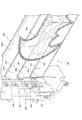
次に、図28〜図30を参照して、シャッタ部材201,202,203,204を発光させる構造について説明する。
Next, with reference to FIGS. 28 to 30, a structure for causing the
図28に示すように、シャッタ装置200は、シャッタ部材201,202,203,204に側方から光を照射する光照射手段としての光照射装置400を、シャッタ部材201,202,203,204の長手方向の両端部側に2つ備えている。また、これら光照射装置400は、支持部材400aを介してシャッタベース220の側片部222,223にそれぞれ固定されている。
As shown in FIG. 28, the
光照射装置400は、シャッタ部材201,202,203,204のそれぞれに対応して上下方向に並べて配置された4つのLED401,402,403,404を有している。LED401,402,403,404は、上述したLED群25(図3参照)に含まれる。
The
また、シャッタ部材201,202,203,204は、一方の面(本実施の形態では、裏面201b〜204b)の少なくとも一部に装飾500が施されている。この装飾500は、任意の形状で描かれ、特に図28に示した形状に限られない。
In addition, in the
図29に示すように、裏面201b〜204bの装飾500が施された箇所には、LED401,402,403,404から照射された光をパチスロ機1(図2参照)の前面側に向かって反射させる凹凸501が形成されている。
As shown in FIG. 29, the light emitted from the
図30に示すように、凹凸501は、LED401,402,403,404から照射された光が図中、矢印で示すように、パチスロ機1の前面側に向かって反射可能な傾斜面501aを有する。なお、図30では、シャッタ部材202の裏面202bに設けられた凹凸501を例に説明したが、他のシャッタ部材の凹凸501も同様に構成されている。
As shown in FIG. 30, the
また、本実施の形態では、LED401,402,403,404は、凹凸501の傾斜面501aに対して所定の角度で光を照射するよう、傾斜した状態で光照射装置400に設置されている。ここで、LED401,402,403,404の設置角度は、傾斜面501aで反射した光がパチスロ機1の前面側に向かうような照射光を傾斜面501aに対して照射可能な角度とされる。より厳密には、LED401,402,403,404の傾斜面501aに対する入射角度と反射角度とを考慮して、LED401,402,403,404の設置角度及び傾斜面501aの角度が設定されるのが好ましい。
Further, in the present embodiment, the
以上のように、本実施の形態に係るパチスロ機1は、昇降可能なシャッタ部材201〜204を有するシャッタ装置200を液晶表示装置11よりもパチスロ機1の前面側に設ける。また、最下位のシャッタ部材201は、昇降ユニット206によって昇降される一方で、スライダ機構210を介して最下位のシャッタ部材201に接続された他のシャッタ部材202〜204は、最下位のシャッタ部材201に連動させて昇降するようになっている。
As described above, in the pachi-slot machine 1 according to the present embodiment, the
これにより、本実施の形態に係るパチスロ機1は、視覚的な演出として、液晶表示装置11による画像演出と、シャッタ部材201の昇降による役物演出とを組み合わせることができる。したがって、本実施の形態に係るパチスロ機1は、意外性に富んだ視覚的な演出を行うことで遊技の興趣を向上させることができる。
Thereby, the pachi-slot machine 1 according to the present embodiment can combine, as visual effects, an image effect by the liquid
また、本実施の形態に係るパチスロ機1は、最下位のシャッタ部材201を昇降させるだけで、全てのシャッタ部材201〜204を連動して昇降させることができる。このため、全てのシャッタ部材201〜204に対応した昇降手段を設ける必要がなく、簡素な構成でシャッタ装置200を構成できる。
Further, the pachi-slot machine 1 according to the present embodiment can raise and lower all the
また、本実施の形態に係るパチスロ機1は、シャッタ部材201〜204の表面201a〜204aが画像表示面11aに対して平行となるよう、ねじりばね262によってシャッタ部材201〜204が一の回転方向(図15(a)中、矢印Gで示す方向)に付勢されているので、シャッタ部材201〜204が昇降する際のがたつきを抑制することができる。これにより、本実施の形態に係るパチスロ機1は、シャッタ部材201〜204の昇降を円滑に行うことができる。
In the pachi-slot machine 1 according to the present embodiment, the
また、本実施の形態に係るパチスロ機1において、露出位置(図17に示す位置)に上昇させられた全てのシャッタ部材201〜204は、それぞれの表面201a〜204aが上方を向くよう回転した状態で互いに重畳されて上部外装部材7aの背面側の空間に収容される。このため、全てのシャッタ部材201〜204を収容した際には、それらシャッタ部材201〜204を遊技者から視認されない上部外装部材7aの背面側に隠すことができる。これにより、シャッタ部材201〜204が下降した際に、遊技者に意外性を与えることができる。
Further, in the pachi-slot machine 1 according to the present embodiment, all
また、本実施の形態に係るパチスロ機1において、シャッタ部材201〜204は、回転機構230の駆動モータ231によって係合部材234が回転駆動されることで、表面201a〜204aと裏面201b〜204bとが反転するよう遮蔽位置(図19に示す位置)で回転させられる。このため、シャッタ部材201〜204によって単に液晶表示装置11を遮蔽するだけでなく、シャッタ部材201〜204の表面201a〜204aと裏面201b〜204bとを反転させることによってシャッタ部材201〜204の動きに意外性を持たせることができる。
Further, in the pachi-slot machine 1 according to the present embodiment, the
また、本実施の形態に係るパチスロ機1において、シャッタ部材201〜204は、その表面201a〜204aが画像表示面11aに対して直交した角度で停止するよう構成されているので、遮蔽位置(図19に示す位置)においても画像表示面11aを遊技者に対して視認させることができる。これにより、シャッタ部材201〜204の動きにさらに意外性を持たせるとともに、遮蔽位置においてもシャッタ部材201〜204と液晶表示装置11とを組み合わせた演出を行うことができる。
Further, in the pachi-slot machine 1 according to the present embodiment, the
また、本実施の形態に係るパチスロ機1は、シャッタ部材201〜204の一方端部301及び他方端部302の断面形状が、シャッタ部材201〜204の表面201a〜204aに直交する方向に互いに離隔した頂点301a,302aを有する形状である。このため、シャッタ部材201〜204を上昇させる際は、下方のシャッタ部材の一方端部301が上方のシャッタ部材の他方端部302に接触することにより上方のシャッタ部材をねじりばね262の付勢力に抗して容易に回転させることができる。
In the pachi-slot machine 1 according to the present embodiment, the cross-sectional shapes of the one
また、本実施の形態に係るパチスロ機1は、シャッタ部材201〜204の一方端部301及び他方端部302が互いに離隔した頂点301a,302aに向けて傾斜した傾斜部301b,302bを有するので、下方のシャッタ部材の一方端部301の傾斜部301bと上方のシャッタ部材の他方端部302の傾斜部302bとの接触によって上方のシャッタ部材を円滑に回転させることができる。
In addition, since the pachi-slot machine 1 according to the present embodiment has the
また、本実施の形態に係るパチスロ機1は、シャッタ部材201〜204の側方に設けられた光照射装置400から光がシャッタ部材201〜204に照射される。また、シャッタ部材201〜204の裏面201b〜204bの装飾の施された箇所には、照射された光をパチスロ機1の前面側に向かって反射させる凹凸501が形成されている。これにより、限られたスペースのなかで、可動役物としてのシャッタ部材201〜204に光を照射できるとともにその反射光を遊技者に認識させることができる。
Further, in the pachi-slot machine 1 according to the present embodiment, light is irradiated to the
また、凹凸501による光の反射によって装飾の施された箇所が発光しているかのような感覚を遊技者に与えることができるため、シャッタ部材自体に発光部を設ける必要がなく、部品コスト及び製造コストを削減することができる。
In addition, since it is possible to give the player a feeling as if the decorated portion emits light due to the reflection of light due to the
また、シャッタ部材201〜204の装飾を際立たせるためには、装飾の施された箇所のみに凹凸501を形成すればよいので、装飾のデザイン変更も容易となる。
In addition, in order to make the decoration of the
本実施の形態に係るパチスロ機1は、シャッタ部材201〜204の裏面201b〜204bの凹凸501が、照射された光をパチスロ機1の前面側に向かって反射可能な傾斜面501aを有するので、光照射装置400から照射された光を確実にパチスロ機1の前面側に向かって反射させることができる。
In the pachislot machine 1 according to the present embodiment, since the
また、本実施の形態では、遊技機としてパチスロ機を用いた例について説明したが、これに限定されるものではなく、例えばパチンコ機等、その他各種の遊技機であってもよい。 Further, in the present embodiment, although an example in which a pachislot machine is used as a game machine has been described, the present invention is not limited to this. For example, other various game machines such as a pachinko machine may be used.
[付記]
本発明に係る遊技機は、上記目的達成のため、複数の図柄が表示された複数のリール(3L,3C,3R)と、遊技者の操作に応じて前記複数のリールの回転を開始させる開始操作手段(スタートレバー16)と、前記複数のリールに対応して設けられ、遊技者の操作に応じて対応する各リールの回転を停止させる停止操作手段(ストップボタン17L,17C,17R)と、画像を表示する画像表示手段(液晶表示装置11)と、前記画像表示手段よりも遊技機の前面側に設けられ、前記画像表示手段を遮蔽する遮蔽位置(図19に示す位置)と前記画像表示手段を露出させるよう前記遮蔽位置よりも上方に設けられた露出位置(図17に示す位置)との間で昇降可能な複数枚(例えば、4枚)の板状のシャッタ部材(201,202,203,204)を有するシャッタ装置(200)と、を備え、前記シャッタ装置は、前記複数枚のシャッタ部材のうち、最下位のシャッタ部材(201)を昇降させる昇降手段(昇降ユニット206)と、前記最下位のシャッタ部材以外の他のシャッタ部材(202,203,204)を前記最下位のシャッタ部材に連動させて昇降するよう、前記最下位のシャッタ部材と前記他のシャッタ部材とを接続する接続手段(スライダ機構210)と、前記画像表示手段の画像表示面(11a)と前記シャッタ部材の表面(201a,202a,203a,204a)とのなす角度が変更されるよう、前記シャッタ部材を回転可能に支持する支持手段(スライダ機構210)と、前記シャッタ部材の表面が前記画像表示面に対して平行となるよう前記シャッタ部材を一の回転方向に付勢する付勢手段(ねじりばね262)と、前記シャッタ部材が前記遮蔽位置に下降した際に前記シャッタ部材に係合する係合部材(234)を有する回転機構(230)と、を有し、前記回転機構は、前記係合部材を回転駆動する駆動部(駆動モータ231)を有し、前記シャッタ部材は、前記駆動部によって前記係合部材が回転駆動されることで、表面と裏面(201b,202b,203b,204b)とが反転するよう前記遮蔽位置で回転させられる構成を有する。
[Supplementary note]
The gaming machine according to the present invention starts to rotate the plurality of reels (3L, 3C, 3R) on which the plurality of symbols are displayed, and the plurality of reels according to the operation of the player to achieve the above object. Operation means (start lever 16), and stop operation means (stop
この構成により、本発明に係る遊技機は、昇降可能な複数枚の板状のシャッタ部材を有するシャッタ装置を画像表示手段よりも遊技機の前面側に設ける。また、最下位のシャッタ部材は、昇降手段によって昇降される一方で、接続手段を介して最下位のシャッタ部材に接続された他のシャッタ部材は、最下位のシャッタ部材に連動させて昇降するようになっている。 According to this configuration, the gaming machine according to the present invention provides the shutter device having the plurality of plate-like shutter members capable of moving up and down on the front side of the gaming machine rather than the image display means. Further, the lowermost shutter member is moved up and down by the raising and lowering means, while the other shutter members connected to the lowermost shutter member through the connecting means are moved up and down in conjunction with the lowermost shutter member. It has become.
これにより、本発明に係る遊技機は、視覚的な演出として、画像表示手段による画像演出と、シャッタ部材の昇降による役物演出とを組み合わせることができる。したがって、本発明に係る遊技機は、意外性に富んだ視覚的な演出を行うことで遊技の興趣を向上させることができる。 Thereby, the gaming machine according to the present invention can combine, as visual effects, an image effect by the image display means and an effect effect by the elevation of the shutter member. Therefore, the gaming machine according to the present invention can improve the interest of the game by performing visual effects rich in surprise.
また、本発明に係る遊技機は、最下位のシャッタ部材を昇降させるだけで、全てのシャッタ部材を連動して昇降させることができる。このため、全てのシャッタ部材に対応した昇降手段を設ける必要がなく、簡素な構成でシャッタ装置を構成できる。 Further, the gaming machine according to the present invention can raise and lower all shutter members in an interlocking manner only by raising and lowering the lowermost shutter member. For this reason, it is not necessary to provide elevation means corresponding to all the shutter members, and the shutter device can be configured with a simple configuration.
また、本発明に係る遊技機は、シャッタ部材の表面が画像表示面に対して平行となるよう、付勢手段によってシャッタ部材が一の回転方向に付勢されているので、シャッタ部材が昇降する際のがたつきを抑制することができる。これにより、本発明に係る遊技機は、シャッタ部材の昇降を円滑に行うことができる。 Further, in the gaming machine according to the present invention, since the shutter member is urged in one rotation direction by the urging means so that the surface of the shutter member is parallel to the image display surface, the shutter member moves up and down It is possible to suppress backlash. Thereby, the gaming machine according to the present invention can smoothly move the shutter member up and down.
また、シャッタ部材は、回転機構の駆動部によって係合部材が回転駆動されることで、表面と裏面とが反転するよう遮蔽位置で回転させられる。このため、シャッタ部材によって単に画像表示手段を遮蔽するだけでなく、シャッタ部材の表面と裏面とを反転させることによってシャッタ部材の動きに意外性を持たせることができる。 Further, the shutter member is rotated at the shielding position so that the front surface and the back surface are reversed by rotationally driving the engagement member by the drive portion of the rotation mechanism. Therefore, the movement of the shutter member can be made surprising by reversing the front and back surfaces of the shutter member as well as simply shielding the image display means by the shutter member.
また、本発明に係る遊技機において、前記シャッタ部材は、前記駆動部によって前記係合部材が所定駆動量だけ回転駆動されることで、前記表面が前記画像表示面に対して直交した角度で停止するよう構成されていることを特徴とする請求項1に記載の遊技機。 Further, in the gaming machine according to the present invention, the shutter member is stopped at an angle at which the surface is orthogonal to the image display surface as the engagement member is rotationally driven by a predetermined driving amount by the drive unit. The gaming machine according to claim 1, wherein the gaming machine is configured to:
この構成により、本発明に係る遊技機において、シャッタ部材は、その表面が画像表示面に対して直交した角度で停止するよう構成されているので、遮蔽位置においても画像表示面を遊技者に対して視認させることができる。これにより、シャッタ部材の動きにさらに意外性を持たせるとともに、遮蔽位置においてもシャッタ部材と画像表示手段とを組み合わせた演出を行うことができる。 With this configuration, in the gaming machine according to the present invention, the shutter member is configured to stop at an angle orthogonal to the image display surface, so that the image display surface can be displayed to the player even in the blocking position. Can be viewed visually. As a result, the movement of the shutter member can be made more surprising, and effects can be produced by combining the shutter member and the image display means even at the blocking position.
1 パチスロ機(遊技機)
3L,3C,3R リール
6 保護ガラス
7a 上部外装部材(外装部材)
9 ドア本体
11 液晶表示装置(画像表示手段)
16 スタートレバー(開始操作手段)
17L,17C,17R ストップボタン(停止操作手段)
78 シャッタ制御基板
200 シャッタ装置
201,202,203,204 シャッタ部材
201a,202a,203a,204a 表面
201b,202b,203b,204b 裏面(一方の面)
203A 回転軸
206 昇降ユニット(昇降手段)
210 スライダ機構(接続手段、支持手段)
211 第1のスライダ
212 第2のスライダ
213 第3のスライダ
214 第4のスライダ
230 回転機構
231 駆動モータ(駆動部)
234 係合部材
240 昇降モータ
260 回転体
262 ねじりばね(付勢手段)
301 一方端部
301b 傾斜部
302 他方端部
302b 傾斜部
301a,302a 頂点
400 光照射装置(光照射手段)
401,402,403,404 LED
500 装飾
501 凹凸
501a 傾斜面
1 Pachislot machine (game machine)
3L, 3C,
9
16 Start lever (Start operation means)
17L, 17C, 17R Stop button (stop operation means)
78
210 Slider mechanism (connection means, support means)
211
234 engaging
301 One
401, 402, 403, 404 LED
500
Claims (1)
前記板状部材の表面のなす角度が変更されるよう、前記板状部材を回転可能に支持する支持手段と、
前記板状部材に係合する係合部材を有する回転機構と、を備え、
前記係合部材は、ギヤ部が一体形成された回転体で構成され、
前記回転機構は、前記係合部材を回転駆動するピニオンギヤを有する駆動部と、前記ピニオンギヤに噛み合う第1のギヤ部、及び、前記回転体のギヤ部に噛み合うとともに、前記ピニオンギヤの回転による前記第1のギヤ部の移動に連動して移動する第2のギヤ部とを有するラック部を備え、
前記板状部材は、前記板状部材の一面が遊技機の前後方向に直交する面に対して平行となったとき、上方に位置する一方端部と、下方に位置する他方端部とを有し、
前記一方端部及び前記他方端部は、前記板状部材の回転軸方向に直交する方向の断面形状が、前記板状部材の平面に直交する方向に互いに離隔した頂点を有する形状であり、
前記板状部材は、昇降手段によって第1の位置と前記第1の位置よりも上方に設けられた第2の位置との間で昇降可能に構成され、
前記係合部材は、前記板状部材が前記第1の位置に下降した際に前記板状部材に係合するよう構成されていることを特徴とする遊技機。 A plurality of plate members,
Supporting means for rotatably supporting the plate-like member such that the angle formed by the surface of the plate-like member is changed;
A rotation mechanism having an engagement member engaged with the plate-like member;
The engagement member is constituted by a rotary body integrally formed with a gear portion,
The rotation mechanism is engaged with a drive portion having a pinion gear for rotationally driving the engagement member, a first gear portion meshing with the pinion gear , and a gear portion of the rotating body , and the first portion by rotation of the pinion gear. A rack portion having a second gear portion that moves in conjunction with the movement of the gear portion of
The plate-like member has one end located at the upper side and the other end located at the lower side when one surface of the plate-like member is parallel to the plane orthogonal to the back and forth direction of the gaming machine. And
Said one end and said other end, the direction of the cross section perpendicular to the rotation axis direction of the plate-like member, Ri shape der having an apex spaced from each other in a direction perpendicular to the plane of the plate-like member,
The plate-like member is configured to be movable up and down between a first position and a second position provided above the first position by elevating means,
It said engaging member is a game machine, wherein Rukoto the plate-like member is configured to engage the plate-like member when lowered to the first position.
Priority Applications (1)
| Application Number | Priority Date | Filing Date | Title |
|---|---|---|---|
| JP2017160097A JP6518736B2 (en) | 2017-08-23 | 2017-08-23 | Gaming machine |
Applications Claiming Priority (1)
| Application Number | Priority Date | Filing Date | Title |
|---|---|---|---|
| JP2017160097A JP6518736B2 (en) | 2017-08-23 | 2017-08-23 | Gaming machine |
Related Parent Applications (1)
| Application Number | Title | Priority Date | Filing Date |
|---|---|---|---|
| JP2014146494A Division JP6199248B2 (en) | 2014-07-17 | 2014-07-17 | Game machine |
Related Child Applications (1)
| Application Number | Title | Priority Date | Filing Date |
|---|---|---|---|
| JP2019080940A Division JP2019136530A (en) | 2019-04-22 | 2019-04-22 | Game machine |
Publications (2)
| Publication Number | Publication Date |
|---|---|
| JP2017202363A JP2017202363A (en) | 2017-11-16 |
| JP6518736B2 true JP6518736B2 (en) | 2019-05-22 |
Family
ID=60321669
Family Applications (1)
| Application Number | Title | Priority Date | Filing Date |
|---|---|---|---|
| JP2017160097A Expired - Fee Related JP6518736B2 (en) | 2017-08-23 | 2017-08-23 | Gaming machine |
Country Status (1)
| Country | Link |
|---|---|
| JP (1) | JP6518736B2 (en) |
Family Cites Families (7)
| Publication number | Priority date | Publication date | Assignee | Title |
|---|---|---|---|---|
| JP4378596B2 (en) * | 2002-10-17 | 2009-12-09 | 株式会社ニューギン | Game machine shutter device |
| JP2008073371A (en) * | 2006-09-22 | 2008-04-03 | Aruze Corp | Game machine |
| JP4946480B2 (en) * | 2007-02-08 | 2012-06-06 | タイヨーエレック株式会社 | Game machine |
| JP4508203B2 (en) * | 2007-02-14 | 2010-07-21 | 株式会社サンセイアールアンドディ | Game machine |
| JP2009142365A (en) * | 2007-12-12 | 2009-07-02 | Sanyo Product Co Ltd | Game machine having shielding member |
| JP5645383B2 (en) * | 2009-09-25 | 2014-12-24 | 株式会社平和 | Game machine accessories |
| JP2012236004A (en) * | 2011-04-28 | 2012-12-06 | Okumura Yu-Ki Co Ltd | Game machine |
-
2017
- 2017-08-23 JP JP2017160097A patent/JP6518736B2/en not_active Expired - Fee Related
Also Published As
| Publication number | Publication date |
|---|---|
| JP2017202363A (en) | 2017-11-16 |
Similar Documents
| Publication | Publication Date | Title |
|---|---|---|
| JP5922714B2 (en) | Game machine | |
| JP6286469B2 (en) | Game machine | |
| JP6522066B2 (en) | Gaming machine | |
| JP5914583B2 (en) | Game machine | |
| JP6370418B2 (en) | Game machine | |
| JP6518736B2 (en) | Gaming machine | |
| JP6199249B2 (en) | Game machine | |
| JP6317204B2 (en) | Game machine | |
| JP2018065018A (en) | Game machine | |
| JP6486531B2 (en) | Game machine | |
| JP6695642B2 (en) | Amusement machine | |
| JP6695641B2 (en) | Amusement machine | |
| JP6782328B2 (en) | Game machine | |
| JP6199248B2 (en) | Game machine | |
| JP6317205B2 (en) | Game machine | |
| JP6313151B2 (en) | Game machine | |
| JP2020078739A (en) | Game machine | |
| JP2020078730A (en) | Game machine | |
| JP2019136530A (en) | Game machine | |
| JP6106785B2 (en) | Game machine | |
| JP6000304B2 (en) | Game machine | |
| JP6511176B2 (en) | Gaming machine | |
| JP6511173B2 (en) | Gaming machine | |
| JP6474844B2 (en) | Game machine | |
| JP6087010B2 (en) | Game machine |
Legal Events
| Date | Code | Title | Description |
|---|---|---|---|
| A621 | Written request for application examination |
Free format text: JAPANESE INTERMEDIATE CODE: A621 Effective date: 20170823 |
|
| A131 | Notification of reasons for refusal |
Free format text: JAPANESE INTERMEDIATE CODE: A131 Effective date: 20180904 |
|
| A521 | Request for written amendment filed |
Free format text: JAPANESE INTERMEDIATE CODE: A523 Effective date: 20181101 |
|
| TRDD | Decision of grant or rejection written | ||
| A01 | Written decision to grant a patent or to grant a registration (utility model) |
Free format text: JAPANESE INTERMEDIATE CODE: A01 Effective date: 20190326 |
|
| A61 | First payment of annual fees (during grant procedure) |
Free format text: JAPANESE INTERMEDIATE CODE: A61 Effective date: 20190422 |
|
| R150 | Certificate of patent or registration of utility model |
Ref document number: 6518736 Country of ref document: JP Free format text: JAPANESE INTERMEDIATE CODE: R150 |
|
| LAPS | Cancellation because of no payment of annual fees |