JP6518698B2 - Method of forming an article comprising a particle path with an exposed end - Google Patents
Method of forming an article comprising a particle path with an exposed end Download PDFInfo
- Publication number
- JP6518698B2 JP6518698B2 JP2016568555A JP2016568555A JP6518698B2 JP 6518698 B2 JP6518698 B2 JP 6518698B2 JP 2016568555 A JP2016568555 A JP 2016568555A JP 2016568555 A JP2016568555 A JP 2016568555A JP 6518698 B2 JP6518698 B2 JP 6518698B2
- Authority
- JP
- Japan
- Prior art keywords
- matrix
- particles
- water
- soluble
- viscous material
- Prior art date
- Legal status (The legal status is an assumption and is not a legal conclusion. Google has not performed a legal analysis and makes no representation as to the accuracy of the status listed.)
- Active
Links
Images


Classifications
-
- B—PERFORMING OPERATIONS; TRANSPORTING
- B29—WORKING OF PLASTICS; WORKING OF SUBSTANCES IN A PLASTIC STATE IN GENERAL
- B29C—SHAPING OR JOINING OF PLASTICS; SHAPING OF MATERIAL IN A PLASTIC STATE, NOT OTHERWISE PROVIDED FOR; AFTER-TREATMENT OF THE SHAPED PRODUCTS, e.g. REPAIRING
- B29C41/00—Shaping by coating a mould, core or other substrate, i.e. by depositing material and stripping-off the shaped article; Apparatus therefor
- B29C41/003—Shaping by coating a mould, core or other substrate, i.e. by depositing material and stripping-off the shaped article; Apparatus therefor characterised by the choice of material
-
- C—CHEMISTRY; METALLURGY
- C09—DYES; PAINTS; POLISHES; NATURAL RESINS; ADHESIVES; COMPOSITIONS NOT OTHERWISE PROVIDED FOR; APPLICATIONS OF MATERIALS NOT OTHERWISE PROVIDED FOR
- C09J—ADHESIVES; NON-MECHANICAL ASPECTS OF ADHESIVE PROCESSES IN GENERAL; ADHESIVE PROCESSES NOT PROVIDED FOR ELSEWHERE; USE OF MATERIALS AS ADHESIVES
- C09J9/00—Adhesives characterised by their physical nature or the effects produced, e.g. glue sticks
- C09J9/02—Electrically-conducting adhesives
-
- H—ELECTRICITY
- H01—ELECTRIC ELEMENTS
- H01B—CABLES; CONDUCTORS; INSULATORS; SELECTION OF MATERIALS FOR THEIR CONDUCTIVE, INSULATING OR DIELECTRIC PROPERTIES
- H01B1/00—Conductors or conductive bodies characterised by the conductive materials; Selection of materials as conductors
- H01B1/20—Conductive material dispersed in non-conductive organic material
- H01B1/22—Conductive material dispersed in non-conductive organic material the conductive material comprising metals or alloys
-
- B—PERFORMING OPERATIONS; TRANSPORTING
- B29—WORKING OF PLASTICS; WORKING OF SUBSTANCES IN A PLASTIC STATE IN GENERAL
- B29C—SHAPING OR JOINING OF PLASTICS; SHAPING OF MATERIAL IN A PLASTIC STATE, NOT OTHERWISE PROVIDED FOR; AFTER-TREATMENT OF THE SHAPED PRODUCTS, e.g. REPAIRING
- B29C41/00—Shaping by coating a mould, core or other substrate, i.e. by depositing material and stripping-off the shaped article; Apparatus therefor
- B29C41/02—Shaping by coating a mould, core or other substrate, i.e. by depositing material and stripping-off the shaped article; Apparatus therefor for making articles of definite length, i.e. discrete articles
-
- B—PERFORMING OPERATIONS; TRANSPORTING
- B29—WORKING OF PLASTICS; WORKING OF SUBSTANCES IN A PLASTIC STATE IN GENERAL
- B29C—SHAPING OR JOINING OF PLASTICS; SHAPING OF MATERIAL IN A PLASTIC STATE, NOT OTHERWISE PROVIDED FOR; AFTER-TREATMENT OF THE SHAPED PRODUCTS, e.g. REPAIRING
- B29C41/00—Shaping by coating a mould, core or other substrate, i.e. by depositing material and stripping-off the shaped article; Apparatus therefor
- B29C41/34—Component parts, details or accessories; Auxiliary operations
- B29C41/50—Shaping under special conditions, e.g. vacuum
-
- C—CHEMISTRY; METALLURGY
- C09—DYES; PAINTS; POLISHES; NATURAL RESINS; ADHESIVES; COMPOSITIONS NOT OTHERWISE PROVIDED FOR; APPLICATIONS OF MATERIALS NOT OTHERWISE PROVIDED FOR
- C09J—ADHESIVES; NON-MECHANICAL ASPECTS OF ADHESIVE PROCESSES IN GENERAL; ADHESIVE PROCESSES NOT PROVIDED FOR ELSEWHERE; USE OF MATERIALS AS ADHESIVES
- C09J7/00—Adhesives in the form of films or foils
- C09J7/20—Adhesives in the form of films or foils characterised by their carriers
- C09J7/22—Plastics; Metallised plastics
- C09J7/24—Plastics; Metallised plastics based on macromolecular compounds obtained by reactions involving only carbon-to-carbon unsaturated bonds
- C09J7/245—Vinyl resins, e.g. polyvinyl chloride [PVC]
-
- H—ELECTRICITY
- H01—ELECTRIC ELEMENTS
- H01B—CABLES; CONDUCTORS; INSULATORS; SELECTION OF MATERIALS FOR THEIR CONDUCTIVE, INSULATING OR DIELECTRIC PROPERTIES
- H01B1/00—Conductors or conductive bodies characterised by the conductive materials; Selection of materials as conductors
- H01B1/14—Conductive material dispersed in non-conductive inorganic material
- H01B1/16—Conductive material dispersed in non-conductive inorganic material the conductive material comprising metals or alloys
-
- H—ELECTRICITY
- H01—ELECTRIC ELEMENTS
- H01B—CABLES; CONDUCTORS; INSULATORS; SELECTION OF MATERIALS FOR THEIR CONDUCTIVE, INSULATING OR DIELECTRIC PROPERTIES
- H01B1/00—Conductors or conductive bodies characterised by the conductive materials; Selection of materials as conductors
- H01B1/14—Conductive material dispersed in non-conductive inorganic material
- H01B1/18—Conductive material dispersed in non-conductive inorganic material the conductive material comprising carbon-silicon compounds, carbon or silicon
-
- H—ELECTRICITY
- H01—ELECTRIC ELEMENTS
- H01B—CABLES; CONDUCTORS; INSULATORS; SELECTION OF MATERIALS FOR THEIR CONDUCTIVE, INSULATING OR DIELECTRIC PROPERTIES
- H01B1/00—Conductors or conductive bodies characterised by the conductive materials; Selection of materials as conductors
- H01B1/20—Conductive material dispersed in non-conductive organic material
- H01B1/24—Conductive material dispersed in non-conductive organic material the conductive material comprising carbon-silicon compounds, carbon or silicon
-
- H—ELECTRICITY
- H01—ELECTRIC ELEMENTS
- H01B—CABLES; CONDUCTORS; INSULATORS; SELECTION OF MATERIALS FOR THEIR CONDUCTIVE, INSULATING OR DIELECTRIC PROPERTIES
- H01B13/00—Apparatus or processes specially adapted for manufacturing conductors or cables
- H01B13/0036—Details
-
- H—ELECTRICITY
- H01—ELECTRIC ELEMENTS
- H01F—MAGNETS; INDUCTANCES; TRANSFORMERS; SELECTION OF MATERIALS FOR THEIR MAGNETIC PROPERTIES
- H01F1/00—Magnets or magnetic bodies characterised by the magnetic materials therefor; Selection of materials for their magnetic properties
- H01F1/01—Magnets or magnetic bodies characterised by the magnetic materials therefor; Selection of materials for their magnetic properties of inorganic materials
- H01F1/03—Magnets or magnetic bodies characterised by the magnetic materials therefor; Selection of materials for their magnetic properties of inorganic materials characterised by their coercivity
- H01F1/12—Magnets or magnetic bodies characterised by the magnetic materials therefor; Selection of materials for their magnetic properties of inorganic materials characterised by their coercivity of soft-magnetic materials
- H01F1/14—Magnets or magnetic bodies characterised by the magnetic materials therefor; Selection of materials for their magnetic properties of inorganic materials characterised by their coercivity of soft-magnetic materials metals or alloys
- H01F1/20—Magnets or magnetic bodies characterised by the magnetic materials therefor; Selection of materials for their magnetic properties of inorganic materials characterised by their coercivity of soft-magnetic materials metals or alloys in the form of particles, e.g. powder
- H01F1/28—Magnets or magnetic bodies characterised by the magnetic materials therefor; Selection of materials for their magnetic properties of inorganic materials characterised by their coercivity of soft-magnetic materials metals or alloys in the form of particles, e.g. powder dispersed or suspended in a bonding agent
-
- H—ELECTRICITY
- H05—ELECTRIC TECHNIQUES NOT OTHERWISE PROVIDED FOR
- H05K—PRINTED CIRCUITS; CASINGS OR CONSTRUCTIONAL DETAILS OF ELECTRIC APPARATUS; MANUFACTURE OF ASSEMBLAGES OF ELECTRICAL COMPONENTS
- H05K3/00—Apparatus or processes for manufacturing printed circuits
- H05K3/10—Apparatus or processes for manufacturing printed circuits in which conductive material is applied to the insulating support in such a manner as to form the desired conductive pattern
- H05K3/105—Apparatus or processes for manufacturing printed circuits in which conductive material is applied to the insulating support in such a manner as to form the desired conductive pattern by conversion of non-conductive material on or in the support into conductive material, e.g. by using an energy beam
-
- B—PERFORMING OPERATIONS; TRANSPORTING
- B29—WORKING OF PLASTICS; WORKING OF SUBSTANCES IN A PLASTIC STATE IN GENERAL
- B29K—INDEXING SCHEME ASSOCIATED WITH SUBCLASSES B29B, B29C OR B29D, RELATING TO MOULDING MATERIALS OR TO MATERIALS FOR MOULDS, REINFORCEMENTS, FILLERS OR PREFORMED PARTS, e.g. INSERTS
- B29K2029/00—Use of polyvinylalcohols, polyvinylethers, polyvinylaldehydes, polyvinylketones or polyvinylketals or derivatives thereof as moulding material
- B29K2029/04—PVOH, i.e. polyvinyl alcohol
-
- B—PERFORMING OPERATIONS; TRANSPORTING
- B29—WORKING OF PLASTICS; WORKING OF SUBSTANCES IN A PLASTIC STATE IN GENERAL
- B29K—INDEXING SCHEME ASSOCIATED WITH SUBCLASSES B29B, B29C OR B29D, RELATING TO MOULDING MATERIALS OR TO MATERIALS FOR MOULDS, REINFORCEMENTS, FILLERS OR PREFORMED PARTS, e.g. INSERTS
- B29K2105/00—Condition, form or state of moulded material or of the material to be shaped
- B29K2105/06—Condition, form or state of moulded material or of the material to be shaped containing reinforcements, fillers or inserts
- B29K2105/16—Fillers
-
- B—PERFORMING OPERATIONS; TRANSPORTING
- B29—WORKING OF PLASTICS; WORKING OF SUBSTANCES IN A PLASTIC STATE IN GENERAL
- B29K—INDEXING SCHEME ASSOCIATED WITH SUBCLASSES B29B, B29C OR B29D, RELATING TO MOULDING MATERIALS OR TO MATERIALS FOR MOULDS, REINFORCEMENTS, FILLERS OR PREFORMED PARTS, e.g. INSERTS
- B29K2505/00—Use of metals, their alloys or their compounds, as filler
- B29K2505/08—Transition metals
- B29K2505/14—Noble metals, e.g. silver, gold or platinum
-
- B—PERFORMING OPERATIONS; TRANSPORTING
- B29—WORKING OF PLASTICS; WORKING OF SUBSTANCES IN A PLASTIC STATE IN GENERAL
- B29K—INDEXING SCHEME ASSOCIATED WITH SUBCLASSES B29B, B29C OR B29D, RELATING TO MOULDING MATERIALS OR TO MATERIALS FOR MOULDS, REINFORCEMENTS, FILLERS OR PREFORMED PARTS, e.g. INSERTS
- B29K2507/00—Use of elements other than metals as filler
- B29K2507/04—Carbon
-
- B—PERFORMING OPERATIONS; TRANSPORTING
- B29—WORKING OF PLASTICS; WORKING OF SUBSTANCES IN A PLASTIC STATE IN GENERAL
- B29K—INDEXING SCHEME ASSOCIATED WITH SUBCLASSES B29B, B29C OR B29D, RELATING TO MOULDING MATERIALS OR TO MATERIALS FOR MOULDS, REINFORCEMENTS, FILLERS OR PREFORMED PARTS, e.g. INSERTS
- B29K2995/00—Properties of moulding materials, reinforcements, fillers, preformed parts or moulds
- B29K2995/0003—Properties of moulding materials, reinforcements, fillers, preformed parts or moulds having particular electrical or magnetic properties, e.g. piezoelectric
- B29K2995/0005—Conductive
-
- B—PERFORMING OPERATIONS; TRANSPORTING
- B29—WORKING OF PLASTICS; WORKING OF SUBSTANCES IN A PLASTIC STATE IN GENERAL
- B29K—INDEXING SCHEME ASSOCIATED WITH SUBCLASSES B29B, B29C OR B29D, RELATING TO MOULDING MATERIALS OR TO MATERIALS FOR MOULDS, REINFORCEMENTS, FILLERS OR PREFORMED PARTS, e.g. INSERTS
- B29K2995/00—Properties of moulding materials, reinforcements, fillers, preformed parts or moulds
- B29K2995/0003—Properties of moulding materials, reinforcements, fillers, preformed parts or moulds having particular electrical or magnetic properties, e.g. piezoelectric
- B29K2995/0008—Magnetic or paramagnetic
-
- B—PERFORMING OPERATIONS; TRANSPORTING
- B29—WORKING OF PLASTICS; WORKING OF SUBSTANCES IN A PLASTIC STATE IN GENERAL
- B29L—INDEXING SCHEME ASSOCIATED WITH SUBCLASS B29C, RELATING TO PARTICULAR ARTICLES
- B29L2031/00—Other particular articles
- B29L2031/34—Electrical apparatus, e.g. sparking plugs or parts thereof
- B29L2031/3462—Cables
-
- C—CHEMISTRY; METALLURGY
- C09—DYES; PAINTS; POLISHES; NATURAL RESINS; ADHESIVES; COMPOSITIONS NOT OTHERWISE PROVIDED FOR; APPLICATIONS OF MATERIALS NOT OTHERWISE PROVIDED FOR
- C09J—ADHESIVES; NON-MECHANICAL ASPECTS OF ADHESIVE PROCESSES IN GENERAL; ADHESIVE PROCESSES NOT PROVIDED FOR ELSEWHERE; USE OF MATERIALS AS ADHESIVES
- C09J201/00—Adhesives based on unspecified macromolecular compounds
-
- C—CHEMISTRY; METALLURGY
- C09—DYES; PAINTS; POLISHES; NATURAL RESINS; ADHESIVES; COMPOSITIONS NOT OTHERWISE PROVIDED FOR; APPLICATIONS OF MATERIALS NOT OTHERWISE PROVIDED FOR
- C09J—ADHESIVES; NON-MECHANICAL ASPECTS OF ADHESIVE PROCESSES IN GENERAL; ADHESIVE PROCESSES NOT PROVIDED FOR ELSEWHERE; USE OF MATERIALS AS ADHESIVES
- C09J2301/00—Additional features of adhesives in the form of films or foils
- C09J2301/30—Additional features of adhesives in the form of films or foils characterized by the chemical, physicochemical or physical properties of the adhesive or the carrier
- C09J2301/314—Additional features of adhesives in the form of films or foils characterized by the chemical, physicochemical or physical properties of the adhesive or the carrier the adhesive layer and/or the carrier being conductive
-
- C—CHEMISTRY; METALLURGY
- C09—DYES; PAINTS; POLISHES; NATURAL RESINS; ADHESIVES; COMPOSITIONS NOT OTHERWISE PROVIDED FOR; APPLICATIONS OF MATERIALS NOT OTHERWISE PROVIDED FOR
- C09J—ADHESIVES; NON-MECHANICAL ASPECTS OF ADHESIVE PROCESSES IN GENERAL; ADHESIVE PROCESSES NOT PROVIDED FOR ELSEWHERE; USE OF MATERIALS AS ADHESIVES
- C09J2301/00—Additional features of adhesives in the form of films or foils
- C09J2301/40—Additional features of adhesives in the form of films or foils characterized by the presence of essential components
- C09J2301/408—Additional features of adhesives in the form of films or foils characterized by the presence of essential components additives as essential feature of the adhesive layer
-
- C—CHEMISTRY; METALLURGY
- C09—DYES; PAINTS; POLISHES; NATURAL RESINS; ADHESIVES; COMPOSITIONS NOT OTHERWISE PROVIDED FOR; APPLICATIONS OF MATERIALS NOT OTHERWISE PROVIDED FOR
- C09J—ADHESIVES; NON-MECHANICAL ASPECTS OF ADHESIVE PROCESSES IN GENERAL; ADHESIVE PROCESSES NOT PROVIDED FOR ELSEWHERE; USE OF MATERIALS AS ADHESIVES
- C09J2429/00—Presence of polyvinyl alcohol
- C09J2429/006—Presence of polyvinyl alcohol in the substrate
Description
本発明は、可溶性マトリックスと、粘性材料および粒子を含むマトリックスとの界面に粒子を配置する方法に関する。可溶性マトリックスと、粘性材料および粒子を含むマトリックスとは本質的に互いに混和することなく、粘性材料および粒子を含むマトリックスは溶解せず、あるいは本質的に溶解することなく、可溶性マトリックスの選択的な溶解を許容するための異なる溶解性を示す。本発明は、前記方法によって得られる物品にも関する。 The present invention relates to a method of disposing particles at the interface of a soluble matrix and a matrix comprising a viscous material and particles. Selective dissolution of the soluble matrix essentially without the soluble matrix and the matrix comprising the viscous material and the particles being miscible with one another, the matrix comprising the viscous material and the particles being undissolved or essentially non-dissolving Exhibit different solubilities to allow. The invention also relates to an article obtainable by said method.
異方性材料は、広範かつ増加する様々な用途において形成されている。典型的には、そのような材料は非導電性マトリックス材料中に固定された導電性粒子を含む。導電性粒子は、異方性材料を少なくとも特定の状況下で導電性にすることができるように、マトリックス材料内に導電性経路を形成することを目的としている。 Anisotropic materials are being formed in a wide variety of increasing applications. Typically, such materials comprise conductive particles immobilized in a nonconductive matrix material. The conductive particles are intended to form conductive pathways in the matrix material so that the anisotropic material can be made conductive at least under certain circumstances.
粒子およびマトリックス材料の選択に応じて、応力センサーなどのセンサー、太陽電池用途、プリンテッド・エレクトロニクス、コンデンサ、バッテリ、タッチスクリーン、ディスプレイ、スマートウィンドウおよび膜などの各種用途に適するように異方性材料を形成することができる。 Depending on the choice of particles and matrix material, anisotropic material to be suitable for various applications such as sensors such as stress sensors, solar cell applications, printed electronics, capacitors, batteries, touch screens, displays, smart windows and films Can be formed.
異方性材料を形成するための先行技術の方法は多くの場合、マトリックス材料および導電性粒子を含む粘性混合物を用意する工程と、導電性粒子を整列させて混合物中に導電性経路を形成させるために粘性混合物に電場を印加する工程と、その後に粘性混合物を硬化させる工程とを含む。 Prior art methods for forming anisotropic materials often include the steps of providing a viscous mixture comprising the matrix material and the conductive particles, and aligning the conductive particles to form conductive pathways in the mixture. Applying an electric field to the viscous mixture and thereafter curing the viscous mixture.
あるいは、当該粒子の磁気特性を使用して当該粒子を整列させて導電性経路を形成することが提案されている。特許文献1はそのような例であり、ここでは、複数の磁性粒子を含む粘塑性材料を、磁性粒子の一部を所定の位置に少なくとも部分的に整列させるのに十分な時間にわたって磁場に曝す。 Alternatively, it has been proposed to align the particles to form conductive pathways using the magnetic properties of the particles. U.S. Pat. No. 5,959,095 is such an example, wherein a viscoplastic material comprising a plurality of magnetic particles is exposed to a magnetic field for a time sufficient to at least partially align the magnetic particles in place. .
しかし、先行技術の方法では一般に、マトリックス材料内に埋め込まれた導電性経路を含む異方性材料が得られるため、導電性経路の終点が異方性材料の表面または縁部で露出されている場合にのみ導電性経路との直接接触が起こり得る。このような導電性経路のごく一部のみの露出は、導電性経路のより大きな部分へのアクセスを必要とする用途では欠点になり得、材料の導電性を低下させることがあり、全ての電流が非常に限られた数の露出された接触点を通らなければならない。 However, since the prior art methods generally result in an anisotropic material comprising conductive pathways embedded in the matrix material, the endpoints of the conductive pathways are exposed at the surface or edge of the anisotropic material Direct contact with the conductive path can occur only in certain cases. Exposure of only a fraction of such conductive pathways can be a disadvantage in applications requiring access to larger portions of the conductive pathway, which can reduce the conductivity of the material, and all current flow There is a very limited number of exposed contact points to pass through.
従って、異方性材料の汎用性をさらに高めるために、導電性経路を完全に露出可能にすること、または導電性ネットワークに対して露出されたノード(nodes)の数を著しく増加させることが望まれている。異方性材料の所望の使用に応じて、導電性経路の少なくとも一部を穏やかな除去手段を用いて部分的または完全に露出させることができる。 Therefore, it is desirable to make the conductive path completely accessible or to significantly increase the number of exposed nodes to the conductive network in order to further enhance the versatility of the anisotropic material. It is rare. Depending on the desired use of the anisotropic material, at least a portion of the conductive pathway can be partially or completely exposed using gentle removal means.
この分野では、形成された異方性材料の汎用性を高め、かつその工業生産を可能にする材料の形成方法が必要とされている。 There is a need in the art for a method of forming a material that enhances the versatility of the formed anisotropic material and enables its industrial production.
本発明の目的は、上述の要求を満たすための方法を提供することにある。 The object of the present invention is to provide a method for meeting the above-mentioned needs.
上記目的は、可溶性マトリックスと粘性材料および粒子を含むマトリックスとの界面に粒子を配置する方法によって達成される。 The above object is achieved by a method of disposing particles at the interface of a soluble matrix and a matrix comprising viscous material and particles.
本方法は、
可溶性マトリックスおよび/または粘性材料および粒子を含むマトリックスを、可溶性マトリックスおよび/または粘性材料および粒子を含むマトリックスに面する少なくとも1つの側面を含む支持体と接触させる工程と、
可溶性マトリックスを粘性材料および粒子を含むマトリックスと接触させた状態で配置し、それにより前記可溶性マトリックスと前記粘性材料および粒子を含むマトリックスとの間に少なくとも1つの界面を含む構造を得る工程と、
前記構造内の粒子を電場および/または磁場に曝し、それにより当該粒子を、可溶性マトリックスと粘性材料および粒子を含むマトリックスとの少なくとも1つの界面に終端を含む少なくとも1つの粒子経路に形成する工程と、
少なくとも1つの粒子経路を固定させるために粘性材料を固定させる工程と
を含み、
前記終端は可溶性マトリックスを除去したときに露出可能になることを特徴とする。
This method is
Contacting the matrix comprising the soluble matrix and / or the viscous material and the particles with the support comprising at least one side facing the matrix comprising the soluble matrix and / or the viscous material and the particles,
Placing the soluble matrix in contact with a matrix comprising a viscous material and particles, thereby obtaining a structure comprising at least one interface between the soluble matrix and the matrix comprising the viscous material and particles;
Subjecting the particles in the structure to an electric and / or magnetic field, thereby forming the particles in at least one particle path comprising terminations at at least one interface between a soluble matrix and a viscous material and a matrix comprising particles. ,
Immobilizing the viscous material to immobilize at least one particle path,
The termination is characterized in that it becomes accessible when the soluble matrix is removed.
可溶性マトリックスは、水溶性マトリックスまたは非水溶性マトリックスであってもよい。当該終端は、可溶性マトリックスを除去したときに露出させることができる。可溶性マトリックスの除去は溶解によって行ってもよい。従って、水溶性もしくは非水溶性マトリックスと粘性材料および粒子を含むマトリックスとの界面に粒子を配置する方法が提供され、
前記方法は、
水溶性もしくは非水溶性マトリックスおよび/または粘性材料および粒子を含むマトリックスを、水溶性もしくは非水溶性マトリックスおよび/または粘性材料および粒子を含むマトリックスに面する少なくとも1つの側面を含む支持体と接触させる工程と、
水溶性もしくは非水溶性マトリックスを粘性材料および粒子を含むマトリックスと接触させた状態で配置し、それにより前記水溶性もしくは非水溶性マトリックスと前記粘性材料および粒子を含むマトリックスとの間に少なくとも1つの界面を含む構造を得る工程と、
前記構造内の粒子を電場および/または磁場に曝し、それにより当該粒子を、水溶性もしくは非水溶性マトリックスと粘性材料および粒子を含むマトリックスとの少なくとも1つの界面に終端を含む少なくとも1つの粒子経路に形成する工程と、
少なくとも1つの粒子経路を固定させるために粘性材料を固定させる工程と
を含み、
前記終端は、水溶性もしくは非水溶性マトリックスの溶解により除去したときに露出されることを特徴とする。
The soluble matrix may be a water soluble matrix or a water insoluble matrix. The ends can be exposed when the soluble matrix is removed. Removal of the soluble matrix may be performed by lysis. Thus, there is provided a method of placing particles at the interface of a water soluble or water insoluble matrix and a matrix comprising viscous material and particles,
The method is
A matrix comprising a water soluble or water insoluble matrix and / or a viscous material and particles is contacted with a water soluble or water insoluble matrix and / or a support comprising at least one side facing the matrix comprising a viscous material and particles Process,
A water soluble or water insoluble matrix is placed in contact with a matrix comprising a viscous material and particles, whereby at least one between the water soluble or water insoluble matrix and a matrix comprising the viscous material and particles Obtaining a structure including an interface;
Exposing particles in the structure to an electric and / or magnetic field, whereby the particles are terminated at at least one interface between a water soluble or water insoluble matrix and a matrix comprising viscous material and particles at least one particle path Forming in
Immobilizing the viscous material to immobilize at least one particle path,
Said terminations are characterized in that they are exposed when removed by dissolution of a water soluble or water insoluble matrix.
可溶性マトリックスは粒子をさらに含んでいてもよい。当該粒子は、粘性材料および粒子を含むマトリックスに含まれるものと同じであっても異なってもよい。可溶性マトリックスへの粒子の添加により、可溶性マトリックスと粘性材料を含むマトリックスとの界面における粒子の濃度の増加を可能にし、かつ/または、確実に粒子が粘性材料を含むマトリックスから可溶性マトリックスの中に突出することができるようにする。電場および/または磁場を印加するとすぐに、当該粒子は、可溶性マトリックスと粘性材料を含むマトリックスとの界面に配置された終端を含む少なくとも1つの粒子経路を形成する。前記粒子の最小長さ寸法が可溶性マトリックスの厚さよりも大きい限り、前記粒子の少なくとも一部が粘性材料を含むマトリックス内に含まれる。粘性材料を含むマトリックスを固定させた後、前記粒子は、可溶性マトリックスをその後に除去した場合であっても、粘性材料を含むマトリックス内に含まれて固定される。可溶性マトリックスを除去した際には、その中にのみ含まれる粒子も除去される。 The soluble matrix may further comprise particles. The particles may be the same as or different from those contained in the matrix comprising the viscous material and the particles. Addition of particles to the soluble matrix allows for an increase in the concentration of particles at the interface between the soluble matrix and the matrix comprising the viscous material and / or ensures that the particles protrude from the matrix comprising the viscous material into the soluble matrix To be able to Upon application of the electric and / or magnetic field, the particles form at least one particle path including an end disposed at the interface of the soluble matrix and the matrix comprising the viscous material. As long as the minimum length dimension of the particles is greater than the thickness of the soluble matrix, at least a portion of the particles are contained within the matrix comprising the viscous material. After immobilizing the matrix comprising the viscous material, the particles are contained and immobilized within the matrix comprising the viscous material, even when the soluble matrix is subsequently removed. When the soluble matrix is removed, particles contained only in it are also removed.
可溶性マトリックス、および/または、粘性材料および粒子を含むマトリックスを支持体と接触させてもよい。上記のように、可溶性マトリックスは粒子を含んでいてもよい。支持体の使用により取り扱いを容易にする。例えば、可溶性マトリックスを支持体と接触させ、その後に粘性材料および粒子を含むマトリックスを可溶性マトリックスに塗布してもよい。可溶性マトリックスの塗布前または後に、粘性材料を支持体と接触させてもよい。可溶性マトリックスおよび粘性材料および粒子を含むマトリックスのために使用される支持体は同じであっても異なってもよく、可溶性マトリックスおよび/または粘性マトリックスに面する少なくとも1つの側面が設けられていてもよい。 A soluble matrix, and / or a matrix comprising a viscous material and particles may be contacted with the support. As mentioned above, the soluble matrix may comprise particles. Handling is facilitated by the use of a support. For example, the soluble matrix may be contacted with a support, and then the matrix comprising the viscous material and the particles may be applied to the soluble matrix. The viscous material may be contacted with the support before or after application of the soluble matrix. The support used for the soluble matrix and the matrix comprising the viscous material and the particles may be the same or different and may be provided with at least one side facing the soluble matrix and / or the viscous matrix .
例えば接着剤または被覆層の塗布の点でその特性を修正するために、固体担体の少なくとも1つの側面を表面改質技術で処理してもよい。一例として、表面改質技術は、当該技術分野で知られているコロナ、プラズマまたは火炎処理であってもよい。適当な表面改質技術を選択することにより、支持体を堆積させ、かつ/または除去するのに望ましい表面特性を達成してもよい。 At least one side of the solid support may be treated with surface modification techniques in order to modify its properties, for example in terms of application of the adhesive or coating layer. As an example, the surface modification technique may be corona, plasma or flame treatment known in the art. By selecting an appropriate surface modification technique, the desired surface properties for depositing and / or removing the support may be achieved.
支持体は、1種以上のポリマーを含む固体材料で作られていてもよい。例えば、支持体としては、限定されるものではないが、当業者に知られているようなポリエチレンテレフタレート(PET)やポリエチレンナフタレート(PEN)などのポリエステル、ポリプロピレン(PP)、ポリカーボネート(PC)またはポリイミド(PI)が挙げられる。支持体はガラスまたは金属などの硬質材料であってもよい。 The support may be made of a solid material comprising one or more polymers. For example, the support may be, but is not limited to, polyesters such as polyethylene terephthalate (PET) or polyethylene naphthalate (PEN), polypropylene (PP), polycarbonate (PC) or polycarbonate (PC) as known to the person skilled in the art Polyimide (PI) is mentioned. The support may be a rigid material such as glass or metal.
支持体に塗布される可溶性マトリックスにより支持体を部分的または完全に覆ってもよい。可溶性マトリックスを被覆、層または薄膜として支持体上に塗布してもよい。被覆、層または薄膜の厚さは用途によって異なってもよい。例えば、被覆、層または薄膜の厚さは0.05μm(マイクロメートル)〜200μmまたは0.15μm〜20μmの範囲であってもよい。 The support may be partially or completely covered by a soluble matrix applied to the support. The soluble matrix may be applied as a coating, layer or film on a support. The thickness of the coating, layer or film may vary depending on the application. For example, the thickness of the coating, layer or film may be in the range of 0.05 μm (micrometers) to 200 μm or 0.15 μm to 20 μm.
「可溶性マトリックスと粘性材料および粒子を含むマトリックスとの界面」という表現は、可溶性マトリックスと粘性材料および粒子を含むマトリックスとの境界領域であると理解される。 The expression “the interface between the soluble matrix and the matrix comprising the viscous material and the particles” is understood to be the boundary region between the soluble matrix and the matrix comprising the viscous material and the particles.
当然のことながら、可溶性マトリックスと粘性材料および粒子を含むマトリックスは互いに混和せず、あるいは非常に限られた程度で互いに混和する。従って、可溶性マトリックスと粘性材料および粒子を含むマトリックスは混和しなくてもよい。あるいは、可溶性マトリックスと粘性材料を含むマトリックスは1〜5重量%などの限られた程度で混和してもよい。従って、可溶性マトリックスを粘性材料および粒子を含むマトリックスと接触させた状態で配置することにより、可溶性マトリックスと粘性材料を含むマトリックスとの間に少なくとも1つの界面の形成が生じる。可溶性マトリックスと粘性材料を含むマトリックスとを接触させた場合、可溶性マトリックスの破壊または拡散は全く生じないか限られた程度でしか生じず、その逆の場合も同様である。粘性材料を含むマトリックスを可溶性マトリックス上に堆積させることにより、可溶性マトリックスと粘性材料を含むマトリックスとを接触させてもよい。 It will be appreciated that the soluble matrix and the matrix comprising the viscous material and the particles are immiscible with one another or with one another to a very limited extent. Thus, the soluble matrix and the matrix comprising the viscous material and the particles may not be miscible. Alternatively, the soluble matrix and the matrix comprising the viscous material may be mixed to a limited extent, such as 1 to 5% by weight. Thus, placing the soluble matrix in contact with the matrix comprising the viscous material and the particles results in the formation of at least one interface between the soluble matrix and the matrix comprising the viscous material. When the soluble matrix is brought into contact with a matrix comprising a viscous material, the destruction or diffusion of the soluble matrix may occur at all or only to a limited extent, and vice versa. The soluble matrix may be brought into contact with the matrix comprising the viscous material by depositing the matrix comprising the viscous material on the soluble matrix.
当然のことながら、可溶性マトリックスと粘性材料を含むマトリックスとの界面に配置されている少なくとも1つの粒子経路の終端またはノードは、可溶性マトリックスと粘性材料を含むマトリックスとの境界領域に、および/またはそこに隣接して、および/またはその近くに位置していてもよい。当該界面に位置する粒子は、可溶性マトリックスと粘性材料を含むマトリックスとの間に形成された界面を通って粘性材料を含むマトリックスから可溶性マトリックスの中に突出していてもよい。さらに、少なくとも1つの粒子経路の終端は、粘性材料を含むマトリックスと平面にあるが可溶性マトリックスの中に延在することなくその界面にあってもよい。追加または代わりとして、当該粒子が粘性材料を含むマトリックスから可溶性マトリックスまで自由に移動可能であれば、個々の粒子径は、当該粒子の少なくとも一部が粘性材料を含むマトリックス内に残存するように、可溶性マトリックスの厚さよりも大きくしてもよい。 It will be appreciated that the end or node of at least one particle pathway disposed at the interface of the soluble matrix and the matrix comprising the viscous material is at and / or in the interface region between the soluble matrix and the matrix comprising the viscous material And / or may be located adjacent to The particles located at the interface may protrude from the matrix containing the viscous material into the soluble matrix through the interface formed between the soluble matrix and the matrix containing the viscous material. Furthermore, the end of the at least one particle path may be at the interface with the matrix comprising the viscous material but in a plane but without extending into the soluble matrix. Additionally or alternatively, if the particles are free to move from the matrix comprising the viscous material to the soluble matrix, the individual particle sizes are such that at least a portion of the particles remain in the matrix comprising the viscous material It may be larger than the thickness of the soluble matrix.
本明細書に記載されているように、粘性材料を含むマトリックスの粘性材料を固定させることにより、少なくとも1つの粒子経路を固定させる。全体的な結果として、その粒子の少なくとも一部が終端を含む少なくとも1つの粒子経路を形成し、前記終端が可溶性マトリックスと粘性材料および粒子を含むマトリックスとの界面に配置されている構造となる。少なくとも1つの粒子経路は、さらなる粒子経路および/またはさらなる粒子に接続され、それにより粘性材料を含むマトリックスおよび/または可溶性マトリックス内に粒子のネットワークの一部を形成してもよい。従って、少なくとも1つの粒子経路は粒子のネットワークの一部を形成してもよい。可溶性マトリックスを除去した際、少なくとも1つの粒子経路の終端は、粘性材料を含むマトリックス内に位置する粒子の連続的なネットワークと接続するノードとして機能することができる。あるいは、少なくとも1つの粒子経路は単一粒子であってもよく、その場合、可溶性マトリックスの除去により、粘性材料を含むマトリックスの表面で前記単一粒子の一部が露出される。 As described herein, immobilizing the viscous material of the matrix comprising the viscous material immobilizes at least one particle path. The overall result is a structure in which at least a portion of the particles form at least one particle path that includes terminations, said terminations being disposed at the interface of the soluble matrix and the matrix comprising the viscous material and the particles. The at least one particle pathway may be connected to further particle pathways and / or further particles, thereby forming part of the network of particles within the matrix comprising the viscous material and / or the soluble matrix. Thus, at least one particle path may form part of a network of particles. When the soluble matrix is removed, the end of at least one particle path can function as a node that connects with the continuous network of particles located in the matrix containing the viscous material. Alternatively, at least one particle path may be a single particle, in which case removal of the soluble matrix exposes a portion of said single particle at the surface of the matrix comprising the viscous material.
可溶性マトリックスが粘性材料を含むマトリックスの中に突出しない粒子を含む場合、これらの粒子は可溶性マトリックスと共に除去される。 If the soluble matrix comprises particles that do not protrude into the matrix comprising the viscous material, these particles are removed together with the soluble matrix.
粘性材料の固定は、例えば、硬化、セラミックス化(ceramisation)、架橋、ゲル化、照射、乾燥、加熱、焼結または焼成などの任意の好適な方法によって達成してもよい。 Fixing of the viscous material may be accomplished by any suitable method such as, for example, curing, ceramisation, crosslinking, gelation, irradiation, drying, heating, sintering or firing.
硬化は、紫外線(UV)などの化学線、熱、および/または、化学添加剤の添加などによって行ってもよい。 Curing may be performed by actinic radiation such as ultraviolet (UV), heat, and / or addition of chemical additives.
本明細書に記載されている方法における少なくとも1つの粒子経路は、導電性粒子経路であってもよい。 At least one particle path in the methods described herein may be a conductive particle path.
本明細書に記載されている方法は、支持体を除去する工程をさらに含んでもよい。支持体を可溶性マトリックスおよび/または粘性材料および粒子を含むマトリックスから除去してもよい。 The methods described herein may further comprise the step of removing the support. The support may be removed from the matrix comprising the soluble matrix and / or the viscous material and the particles.
剥離または引き離しなどの機械的手段を用いて支持体の除去を行ってもよい。本明細書に記載されているような支持体の少なくとも1つの側面の表面処理により、支持体の除去を容易にしてもよい。2つ以上の支持体がある場合、1つ以上の支持体が除去されるような方法で除去を行ってもよい。例えば、1つ、2つまたは全ての支持体を除去してもよい。支持体の除去後に得られる構造は、可溶性マトリックス、固定された粘性材料を含むマトリックス、および前記可溶性マトリックスと前記粘性材料を含むマトリックスとの少なくとも1つの界面を含むかそれらで構成されていてもよい。固定された粘性材料を含むマトリックスは前記少なくとも1つの粒子経路を含む。さらに、可溶性マトリックスも粒子および/または少なくとも1つの粒子経路を含んでいてもよい。本明細書に記載されているように、少なくとも1つの粒子経路は、接続された粒子のネットワークおよび/またはネットワークの一部を形成していてもよく、あるいは単一粒子であってもよい。少なくとも1つの粒子経路は、可溶性マトリックスと固定された粘性材料を含むマトリックスとの前記界面に終端またはノードを含み、前記終端は可溶性マトリックスを除去したときに露出可能になる。 The removal of the support may be performed using mechanical means such as peeling or pulling away. Surface treatment of at least one side of the support as described herein may facilitate removal of the support. If there is more than one support, removal may be done in such a way that one or more supports are removed. For example, one, two or all supports may be removed. The structure obtained after removal of the support may comprise or consist of a soluble matrix, a matrix comprising a fixed viscous material, and at least one interface between said soluble matrix and a matrix comprising said viscous material . The matrix comprising the immobilized viscous material comprises the at least one particle path. Furthermore, the soluble matrix may also comprise particles and / or at least one particle pathway. As described herein, the at least one particle path may form part of a network and / or a network of connected particles, or may be a single particle. At least one particle pathway includes an end or node at the interface of the soluble matrix and the matrix comprising the immobilized viscous material, the end being accessible when the soluble matrix is removed.
支持体の除去後に、
可溶性マトリックスと、
固定された粘性材料を含むマトリックスと、
前記可溶性マトリックスと前記粘性材料を含むマトリックスとの少なくとも1つの界面と、
前記界面に終端を含む少なくとも1つの粒子経路と
を含む物品が提供される。
After removal of the support
Soluble matrix,
A matrix comprising a fixed viscous material,
At least one interface between the soluble matrix and a matrix comprising the viscous material;
An article is provided that includes at least one particle path that includes an end at the interface.
当該物品は、前記終端が前記可溶性マトリックスを除去したときに露出可能になることを特徴とする。可溶性マトリックスおよび/または固定された粘性材料を含むマトリックスは、終端を含む少なくとも1つの粒子経路を含んでいてもよい。当該物品は、本明細書に記載されている方法によって得られてもよい。 The article is characterized in that the end becomes accessible when the soluble matrix is removed. The matrix comprising the soluble matrix and / or the immobilized viscous material may comprise at least one particle pathway comprising an end. The article may be obtained by the method described herein.
可溶性マトリックスは、少なくとも1つの粒子経路の終端のための保護体として機能してもよく、それにより取り扱いおよび輸送を容易にする。保護体である可溶性マトリックスは、被覆、層または薄膜の形状を有していてもよい。この保護体は、当該構造を取り扱う必要がある限り維持してもよく、使用前に容易に除去してもよい。 The soluble matrix may function as a protector for the termination of at least one particle pathway, thereby facilitating handling and transport. The soluble matrix which is a protective body may have the form of a coating, a layer or a thin film. This protection may be maintained as long as the structure needs to be handled or may be easily removed prior to use.
従って、本明細書に記載されている方法は、化学的手段によって可溶性マトリックスを除去する工程をさらに含んでもよい。 Thus, the methods described herein may further comprise the step of removing the soluble matrix by chemical means.
当然のことながら、固定された粘性材料を含むマトリックスを溶解または損傷することなく可溶性マトリックスを溶解することができるように、可溶性マトリックスおよび固定された粘性材料を含むマトリックスの溶解度は異なる。可溶性マトリックスは水溶性マトリックスであると有利であり得る。水溶性マトリックスの除去に適した化学的手段の例としては、水および/または水溶液で洗い流すことが挙げられる。非水溶性マトリックスの除去に適した化学的手段の例としては、酸、塩基、あるいは、アルコール、エステル、ケトン、アルデヒド、エーテル、または炭化水素などの有機溶媒で洗い流すことが挙げられる。可溶性マトリックスを除去したときに前記少なくとも1つの粒子経路の終端は露出される。その結果、前記少なくとも1つの粒子経路の露出された終端は、好都合なことに、外部の電気的手段と接続させることができる。これにより、粘性材料を含むマトリックス内に埋め込まれた少なくとも1つの粒子経路について、前記終端を介して外部の電気的手段に接続させることができるため、これは有意な利点である。さらに、化学的手段による可溶性マトリックスの除去は穏やかな除去方法であり、それにより、固定された粘性材料および/または少なくとも1つの粒子経路の露出された終端の機械的損傷を回避するか最小限に抑える。従って、粒子を損傷し、かつ/または、粒子のネットワークを分断および破壊する恐れのあるエッチングや研磨手順は不要である。 It will be appreciated that the solubility of the soluble matrix and the matrix comprising the immobilized viscous material is different so that the soluble matrix can be dissolved without dissolving or damaging the matrix comprising the immobilized viscous material. The soluble matrix may advantageously be a water soluble matrix. Examples of chemical means suitable for the removal of the water-soluble matrix include rinsing with water and / or an aqueous solution. Examples of chemical means suitable for the removal of water insoluble matrices include washing with acids, bases, or organic solvents such as alcohols, esters, ketones, aldehydes, ethers, or hydrocarbons. The end of the at least one particle path is exposed when the soluble matrix is removed. As a result, the exposed end of said at least one particle path can advantageously be connected with external electrical means. This is a significant advantage, as at least one particle path embedded in the matrix comprising the viscous material can be connected to the external electrical means via said end. Furthermore, removal of the soluble matrix by chemical means is a gentle removal method, thereby avoiding or minimizing mechanical damage of the fixed end of the viscous material and / or the at least one particle path. suppress. Thus, etching and polishing procedures that can damage the particles and / or disrupt and destroy the particle network are not necessary.
対照的に、可溶性マトリックスが存在せず、かつ接着剤またはエラストマー系マトリックスなどの粘性材料を含むマトリックス内の粒子に電場が印加される場合、当該粒子は粘性材料を含むマトリックス内で移動して配置される。粘性材料を含むマトリックスおよび支持体とのその界面の性質またはその自由表面の特性に応じて、当該粒子は、接着剤またはエラストマー系マトリックスなどの粘性材料内に完全に埋め込まれていてもよく、アクセス不可能にされている、すなわち、当該粒子は粘性材料内に埋め込まれ、かつ/またはそれによって覆われているため露出されていない。その結果、外部の電気的手段を当該マトリックス内に配置された粒子に直接接続させることができない。 In contrast, in the absence of a soluble matrix, and when an electric field is applied to particles in a matrix comprising a viscous material such as an adhesive or elastomeric matrix, the particles move and are arranged within the matrix comprising a viscous material Be done. Depending on the nature of the matrix comprising the viscous material and its interface with the support or of the free surface thereof, the particles may be completely embedded within the viscous material, such as an adhesive or an elastomeric matrix, the access It is not possible, i.e. the particles are not exposed as they are embedded in and / or covered by the viscous material. As a result, no external electrical means can be connected directly to the particles arranged in the matrix.
可溶性マトリックスの除去後に得られる構造は、固定された粘性材料を含むマトリックスおよび少なくとも1つの粒子経路を含むかそれらで構成されている。少なくとも1つの粒子経路は、固定された粘性材料の表面で露出された終端を含む。当該構造は1つ以上の支持体をさらに含んでもよい。従って、固定された粘性材料を含むマトリックスと、前記マトリックスの表面に終端を有する少なくとも1つの粒子経路とで構成されているかそれらを含み、前記表面の前記終端が露出されていることを特徴とする物品が提供される。少なくとも1つの粒子経路は、粒子の連続的なネットワークなどの粒子のネットワークの一部を形成してもよい。当該物品は、本明細書に記載されている方法によって得られてもよい。 The structure obtained after removal of the soluble matrix comprises or consists of a matrix comprising immobilized viscous material and at least one particle path. At least one particle path includes the exposed end of the surface of the fixed viscous material. The structure may further comprise one or more supports. Thus, it is characterized in that it comprises or comprises a matrix comprising a fixed viscous material and at least one particle path terminating on the surface of said matrix, said termination of said surface being exposed. An article is provided. The at least one particle path may form part of a network of particles, such as a continuous network of particles. The article may be obtained by the method described herein.
本明細書に記載されている方法によって得られる物品も提供される。 Also provided are articles obtained by the methods described herein.
水溶性マトリックスは水溶性材料を含むかそれで構成されている。例えば、可溶性マトリックスは少なくとも1種の水溶性ポリマーで構成されているかそれを含んでもよい。水溶性ポリマーの例としては、ポリビニルアルコール(PVA)、セルロースエーテル、ポリエチレンオキシド、澱粉、ポリビニルピロリドン、ポリアクリルアミド、ポリビニルメチルエーテル−無水マレイン酸、ポリ無水マレイン酸、スチレン−無水マレイン酸、ヒドロキシエチルセルロース、メチルセルロース、ポリエチレングリコール(PEG)、カルボキシメチルセルロース、ポリアクリル酸塩、アルギン酸塩、アクリルアミドコポリマー、グアーガム、カゼイン、エチレン−無水マレイン酸樹脂、ポリエチレンイミン、エチルヒドロキシエチルセルロース、エチルメチルセルロース、およびヒドロキシエチルメチルセルロースが挙げられる。当然のことながら、可溶性マトリックスは異なる水溶性ポリマーの混合物を含んでもよい。さらに、少なくとも1種のポリマーはポリビニルアルコールであってもよい。可溶性マトリックスは、処理時の取り扱いを改善、および/または、容易にするために1種以上の架橋剤を含んでいてもよい。可溶性マトリックスは、当該産業において層塗布またはレベリング性を改善するための増粘剤またはレベリング剤(levelling agent)として特定されている材料、例えばポリエチレングリコールp−(1,1,3,3−テトラメチルブチル)−フェニルエーテル(TX−100)などの、層被覆品質を高めるための1種以上の添加剤も含んでいてもよい。当該層は着色料または顔料も含んでいてもよい。 The water soluble matrix comprises or consists of a water soluble material. For example, the soluble matrix may be comprised of or include at least one water soluble polymer. Examples of water-soluble polymers include polyvinyl alcohol (PVA), cellulose ether, polyethylene oxide, starch, polyvinyl pyrrolidone, polyacrylamide, polyvinyl methyl ether-maleic anhydride, polymaleic anhydride, styrene-maleic anhydride, hydroxyethyl cellulose, Methylcellulose, polyethylene glycol (PEG), carboxymethylcellulose, polyacrylates, alginates, acrylamide copolymers, guar gum, casein, ethylene-maleic anhydride resin, polyethyleneimine, ethyl hydroxyethyl cellulose, ethyl methyl cellulose, and hydroxyethyl methyl cellulose . It will be appreciated that the soluble matrix may comprise a mixture of different water soluble polymers. Additionally, at least one polymer may be polyvinyl alcohol. The soluble matrix may include one or more crosslinkers to improve and / or facilitate handling during processing. The soluble matrix is a material identified in the industry as a thickener or leveling agent for improving layer application or leveling, eg polyethylene glycol p- (1,1,3,3-tetramethyl) One or more additives may also be included to enhance layer coating quality, such as butyl) -phenyl ether (TX-100). The layer may also contain colorants or pigments.
粘性材料および粒子を含むマトリックスの粘性材料は、1種以上のポリマー、モノマーまたはオリゴマーを含んでもよい。例えば、粘性材料は、接着剤および/またはエラストマー系材料であってもよい。ポリマーは、ポリアクリル酸塩、ポリエポキシド、ポリウレタンおよび/またはポリシリコーンなどの熱硬化性または熱可塑性ポリマーであってもよい。本明細書で使用される粘性マトリックスは、マトリックス材料を通る粒子などの物体の移動にある程度抵抗するため、当該粒子はすぐに沈降しない。例えば、粘性材料は、約1000cP、35000cPまたは約40000cPなどの約300cP以上の粘度を有してもよい。一例として、粘性マトリックスは、約300cP〜約40000cPの範囲内の粘度を有してもよい。本明細書では、cPはセンチポアズを表す。一例として、粘性材料は、約1000cPの粘度を有し得るDymax 3094を含むかそれで構成されていてもよい。さらなる例では、粘性材料は、約300cPの粘度を有し得るNorland NOA81を含むかそれで構成されていてもよい。 The viscous material of the matrix comprising the viscous material and the particles may comprise one or more polymers, monomers or oligomers. For example, the viscous material may be an adhesive and / or an elastomeric material. The polymer may be a thermosetting or thermoplastic polymer such as polyacrylates, polyepoxides, polyurethanes and / or polysilicones. As the viscous matrix used herein resists the movement of objects such as particles through the matrix material to some extent, the particles do not settle immediately. For example, the viscous material may have a viscosity of about 300 cP or more, such as about 1000 cP, 35000 cP, or about 40000 cP. As an example, the viscous matrix may have a viscosity in the range of about 300 cP to about 40000 cP. As used herein, cP stands for centipoise. As an example, the viscous material may comprise or consist of Dymax 3094, which may have a viscosity of about 1000 cP. In a further example, the viscous material may comprise or consist of Norland NOA 81, which may have a viscosity of about 300 cP.
磁場の使用によって移動可能になるように、当該粒子は常磁性または強磁性、好ましくは強磁性であると有利であり得る。 It may be advantageous for the particles to be paramagnetic or ferromagnetic, preferably ferromagnetic, so as to be movable by the use of a magnetic field.
さらに、電場の使用によって移動可能になるように、当該粒子は、導電性であり、かつ/または、当該マトリックスの比誘電率よりも非常に小さいまたは非常に大きい比誘電率を有する1種以上の材料で作られていると有利であり得る。 Furthermore, the particles are electrically conductive and / or have one or more species with a relative permittivity much lower or much higher than the relative permittivity of the matrix so that they can be moved by the use of an electric field. It may be advantageous to be made of materials.
当該粒子は均質な粒子であってもよく、すなわち、粒子は大きさ、形状および/または材料組成において幅のある粒子全体を通して単一の材料または材料混合物で構成されている。但し、当該粒子は不均質な粒子であってもよく、すなわち、粒子はいくつかの材料で構成されている。例えば、当該粒子は1種の材料からなる核および別の材料からなる殻を有していてもよい。当該粒子は、導電性または磁性などの性能を高める不純物も含んでいてもよい。 The particles may be homogeneous particles, i.e. the particles are composed of a single material or mixture of materials throughout the particles in size, shape and / or width of material composition. However, the particles may be heterogeneous particles, ie the particles are composed of several materials. For example, the particles may have a core of one material and a shell of another material. The particles may also contain impurities that enhance performance, such as conductivity or magnetism.
本明細書に記載されている粒子は1種のみの粒子を含んでいてもよいが、異なる種類の粒子の混合物であってもよい。当該粒子は常磁性および/または強磁性であってもよい。また、当該粒子は導電性であってもよい。 The particles described herein may comprise only one type of particle, but may also be a mixture of different types of particles. The particles may be paramagnetic and / or ferromagnetic. Also, the particles may be conductive.
当該粒子は、平坦状であってもよく、かつ/または、球状、細長い形状、管状、円盤状、針金状または不規則形状あるいは形状の組み合わせを有していてもよい。 The particles may be flat and / or have a spherical, elongated shape, tubular, disc-like, wire-like or irregular shape or combination of shapes.
当該粒子は、炭素、金属、および/または金属合金を含んでもよい。例えば、当該粒子は、銀、鉄、グラファイト、ニッケル、銅、金、亜鉛、チタン、またはアルミニウムで構成されているかそれらを含んでもよい。 The particles may comprise carbon, metals, and / or metal alloys. For example, the particles may be comprised of or include silver, iron, graphite, nickel, copper, gold, zinc, titanium, or aluminum.
粒子の少なくとも一部は、常磁性または強磁性、かつ導電性であると有利であり得る。あるいは、常磁性または強磁性の粒子の混合物が存在してもよい。そのような粒子は、磁場および電場の両方によって移動可能である。 At least a portion of the particles may advantageously be paramagnetic or ferromagnetic and conductive. Alternatively, a mixture of paramagnetic or ferromagnetic particles may be present. Such particles are movable by both magnetic and electric fields.
当該粒子は、ニッケルまたは酸化鉄などの金属および/または金属合金の粒子を含むと有利である。当該粒子は、例えばグラファイト、グラフェン、炭素ナノチューブ、バックミンスターフラーレン、非晶質炭素またはカーボンブラックなどの炭素同素体も含んでもよい。さらに、当該粒子を、銀−鉄粒子、銀−ニッケル粒子、グラファイト−ニッケル粒子、ニッケル粒子、炭素−ナノ粒子およびそれらの混合物からなる群から選択してもよい。また、当該粒子は、セラミック、ガラスまたはポリマーのコア(核)と導電性金属のシェル(殻)とを含むコアシェル粒子を含むと有利であり得る。 The particles advantageously comprise particles of metals such as nickel or iron oxide and / or metal alloys. The particles may also comprise carbon allotropes, such as, for example, graphite, graphene, carbon nanotubes, buckminsterfullerenes, amorphous carbon or carbon black. Furthermore, the particles may be selected from the group consisting of silver-iron particles, silver-nickel particles, graphite-nickel particles, nickel particles, carbon-nanoparticles and mixtures thereof. It may also be advantageous for the particles to comprise core-shell particles comprising a core of a ceramic, glass or polymer and a shell of a conductive metal.
粒子径すなわち粒子の最大長さ寸法は、0.3〜500μm、0.5〜200μm、1〜100μm、または3〜50μmの範囲であってもよい。 The particle size or maximum length dimension of the particles may be in the range of 0.3 to 500 μm, 0.5 to 200 μm, 1 to 100 μm, or 3 to 50 μm.
粘性材料を含むマトリックスおよび/または水溶性マトリックス中の粒子の濃度は、パーコレーション閾値未満であってもよい。例えば、当該粒子の濃度は、0.001〜10体積%、0.01〜2体積%、0.01〜1.5体積%、または0.1〜1.5体積の範囲であってもよい。 The concentration of particles in the matrix comprising the viscous material and / or the water-soluble matrix may be below the percolation threshold. For example, the concentration of the particles may be in the range of 0.001 to 10% by volume, 0.01 to 2% by volume, 0.01 to 1.5% by volume, or 0.1 to 1.5 volumes. .
導電性混合物について「パーコレーション閾値」とは、ランダム系において長距離導電率を達成するのに必要な導電性粒子の最低濃度として定義される。そのようなランダム系は、ほぼ等方性である。本発明に係る方法によって形成される系では、所定の方向における導電率を達成するのに必要な導電性粒子の濃度はパーコレーション閾値によって決定されず、その濃度はより低くすることができる。実用的な理由のために、粒子の濃度は導電性経路に対する要件によって決定し、通常、導電性経路内に配置されない過剰な量の導電性粒子を有する理由は存在しない。 The "percolation threshold" for a conductive mixture is defined as the lowest concentration of conductive particles required to achieve long distance conductivity in a random system. Such random systems are nearly isotropic. In the system formed by the method according to the invention, the concentration of conductive particles required to achieve the conductivity in a given direction is not determined by the percolation threshold, which can be lower. For practical reasons, the concentration of particles is determined by the requirements for the conductive path, and there is usually no reason to have an excessive amount of conductive particles not placed in the conductive path.
本明細書に記載されている方法は、支持体への塗布後に可溶性マトリックスを乾燥する工程も含んでもよい。乾燥方法としては、限定されるものではないが、対流加熱、対流を含む赤外線加熱、対流を含まない赤外線加熱、RF乾燥、凍結乾燥などが挙げられる。 The methods described herein may also include the step of drying the soluble matrix after application to a support. Drying methods include, but are not limited to, convection heating, infrared heating including convection, infrared heating not including convection, RF drying, lyophilization and the like.
本明細書に記載されているように水溶性マトリックスと粘性材料および粒子を含むマトリックスとの間に少なくとも1つの界面を含む構造内の粒子に印加される場は、電場、磁場、またはそれら(電場と磁場)の組み合わせであってもよい。電場は、直流電場(DC)または交流電場(AC)であってもよい。RMS電場強度は、1〜100kV/cmの範囲であってよく、1〜50kV/cm、または5〜25kV/cmの範囲であってよい。電場は、0.1kHz〜200kHzまたは0.1kHz〜25kHzなどの10Hz〜10MHzの周波数を有していてもよい。 The field applied to the particles in the structure comprising at least one interface between the water-soluble matrix and the matrix comprising the viscous material and the particles as described herein may be an electric field, a magnetic field or And a magnetic field) may be used. The electric field may be a direct electric field (DC) or an alternating electric field (AC). The RMS field strength may be in the range of 1 to 100 kV / cm, in the range of 1 to 50 kV / cm, or 5 to 25 kV / cm. The electric field may have a frequency of 10 Hz to 10 MHz, such as 0.1 kHz to 200 kHz or 0.1 kHz to 25 kHz.
可溶性マトリックスと粘性材料および粒子を含むマトリックスとの界面の延在部に対して垂直または本質的に垂直な方向に当該場を印加してもよい。当該界面の延在部に対して垂直な方向に当該場を印加した場合、その力線は当該界面の延在部に対して垂直になる。当該界面に対して本質的に垂直な方向に当該場を印加した場合、その力線は、当該界面の延在部に対して垂直な線と共に45度以下の角度をなす。 The field may be applied in a direction perpendicular or essentially perpendicular to the extension of the interface between the soluble matrix and the matrix comprising the viscous material and the particles. When the field is applied in a direction perpendicular to the extension of the interface, the field line is perpendicular to the extension of the interface. When the field is applied in a direction essentially perpendicular to the interface, the field lines make an angle of 45 degrees or less with a line perpendicular to the extension of the interface.
また、当該界面の延在部(extension)に対して平行または本質的に平行な方向に当該場を印加してもよい。当該界面の延在部に対して平行な方向に当該場を印加した場合、その力線は当該界面の延在部に対して平行になる。当該界面の延在部に対して本質的に平行な方向に当該場を印加した場合、その力線は当該界面の延在部に対して45度以下の角度をなす。 The field may also be applied in a direction parallel or essentially parallel to the extension of the interface. When the field is applied in a direction parallel to the extension of the interface, the field lines become parallel to the extension of the interface. If the field is applied in a direction essentially parallel to the extension of the interface, the field lines make an angle of 45 degrees or less with the extension of the interface.
2つ以上の場を印加する場合、可溶性マトリックスと、粘性材料および粒子を含むマトリックスとの界面の延在部に対して垂直または本質的に垂直な方向に、第1の場を印加してもよい。あるいは、当該界面の延在部に対して平行または本質的に平行な方向に、第1の場を印加してもよい。当該界面の延在部に対して垂直または本質的に垂直な方向に、第2および/またはさらなる場を印加してもよい。あるいは、印加されている第2および/またはさらなる場は、当該界面の延在部に対して平行または本質的に平行な力線を有していてもよい。当然のことながら、当該界面の延在部に対して本質的に平行である力線は、当該界面の延在部に対して45度以下の角度をなしていてもよい。 If more than one field is applied, the first field may also be applied in a direction perpendicular or essentially perpendicular to the extension of the interface between the soluble matrix and the matrix comprising the viscous material and the particles. Good. Alternatively, the first field may be applied in a direction parallel or essentially parallel to the extension of the interface. A second and / or further field may be applied in a direction perpendicular or essentially perpendicular to the extension of the interface. Alternatively, the applied second and / or further fields may have lines of force parallel or essentially parallel to the extension of the interface. It will be appreciated that the lines of force essentially parallel to the extension of the interface may form an angle of 45 degrees or less with the extension of the interface.
第1の場は電場または磁場であってもよい。第2またはさらなる場は電場または磁場であってもよい。2つ以上の場を印加する場合、第1の場は電場であってもよく、かつ第2またはさらなる場は磁場であってもよく、あるいはその逆であってもよい。2つ以上の場を印加する場合、当該場を連続的または同時に印加してもよい。 The first field may be an electric or magnetic field. The second or further field may be an electric or magnetic field. If more than one field is applied, the first field may be an electric field and the second or further field may be a magnetic field or vice versa. When two or more fields are applied, the fields may be applied sequentially or simultaneously.
当該粒子に印加される場は、可溶性マトリックスと、粘性材料および粒子を含むマトリックスとの界面の延在部に対して垂直または本質的に垂直な方向に印加される電場であってもよい。 The field applied to the particles may be an electric field applied in a direction perpendicular or essentially perpendicular to the extension of the interface between the soluble matrix and the matrix comprising the viscous material and the particles.
電場および/または磁場を印加した際、少なくとも1つの粒子経路が粘性材料および粒子を含むマトリックス内に形成される。可溶性マトリックスが粒子を含む場合、少なくとも1つの粒子経路が前記可溶性マトリックス内にも形成されてもよい。少なくとも1つの粒子経路は、可溶性マトリックスと、粘性材料および粒子を含むマトリックスとの界面に終端を含む。当該粒子の移動は、使用される場の種類に応じて電気泳動、誘電泳動、磁気泳動、または上記組み合わせによるものであってもよい。粘性材料を含むマトリックス内の粒子の大部分は、粘性材料の中、および/または、可溶性マトリックスと粘性材料を含むマトリックスとの界面近傍に配置されるように移動し、粒子の一部は粘性材料を含むマトリックスから可溶性マトリックスの中にも拡散してもよい。本明細書に記載されているように、少なくとも1つの粒子経路は、粘性材料および粒子を含むマトリックス内に連続的に接続された粒子のネットワークを形成してもよい。可溶性マトリックスの存在により、当該粒子の少なくとも一部は、粘性材料および粒子を含むマトリックスから可溶性マトリックスの中に突出し、かつ/または、可溶性マトリックスと粘性材料を含むマトリックスとの界面に配置されてもよい。 When an electric and / or magnetic field is applied, at least one particle path is formed in the matrix comprising the viscous material and the particles. If the soluble matrix comprises particles, at least one particle pathway may also be formed in the soluble matrix. At least one particle pathway includes an end at the interface of the soluble matrix and the matrix comprising the viscous material and the particles. The migration of the particles may be by electrophoresis, dielectrophoresis, magnetophoresis, or a combination of the above depending on the type of field used. Most of the particles in the matrix containing the viscous material move so as to be disposed in the viscous material and / or near the interface between the soluble matrix and the matrix containing the viscous material, and some of the particles are viscous material May also diffuse into the soluble matrix from the matrix comprising As described herein, the at least one particle pathway may form a network of particles serially connected within a matrix comprising the viscous material and the particles. Due to the presence of the soluble matrix, at least a portion of the particles may protrude from the matrix comprising the viscous material and the particles into the soluble matrix and / or be arranged at the interface between the soluble matrix and the matrix comprising the viscous material .
本明細書に記載されている少なくとも1つの粒子経路は、接続された導電性経路、すなわち、連続的または部分的に連続的なネットワークを形成してもよい。ネットワークの一部である粒子経路は、粘性材料を含むマトリックス内に含まれていてもよく、任意で可溶性マトリックス内にも含まれていてもよい。但し、本明細書に記載されているように、可溶性マトリックスの除去によりその中の粒子も同時に除去される。 At least one particle path described herein may form a connected conductive path, ie, a continuous or partially continuous network. The particle pathways that are part of the network may be contained within the matrix comprising the viscous material, and optionally also within the soluble matrix. However, as described herein, removal of the soluble matrix also simultaneously removes the particles therein.
肉眼で見るか機器を用いて見た際に当該粒子が移動を停止または本質的に停止した場合、当該場の印加を中断してもよい。典型的には、数秒から数分以内に当該プロセスは完了し、工業プロセスにおける本明細書に記載されている方法の使用を可能にする。 The application of the field may be discontinued if the particles have stopped or essentially stopped moving when viewed with the naked eye or using an instrument. Typically, the process is complete within seconds to minutes, allowing the use of the methods described herein in industrial processes.
本明細書に記載されている方法は、
少なくとも1つの側面を含む支持体を用意する工程と、
可溶性マトリックスを前記支持体の前記少なくとも1つの側面に堆積させる工程と、
粘性材料および粒子を含むマトリックスを前記可溶性マトリックス上に堆積させ、それにより可溶性マトリックスと粘性材料および粒子を含むマトリックスとの間に界面を含む構造を得る工程と、
前記構造内の粒子を電場および/または磁場に曝し、それにより当該粒子を、前記界面に終端を含む少なくとも1つの粒子経路に形成する工程と、
少なくとも1つの粒子経路を固定させるために前記粘性材料を固定させる工程と
を含んでもよく、
前記可溶性マトリックスを除去したときに前記終端が露出可能になることを特徴とする。
The methods described herein are:
Providing a support comprising at least one side;
Depositing a soluble matrix on the at least one side of the support;
Depositing a matrix comprising a viscous material and particles onto said soluble matrix, thereby obtaining a structure comprising an interface between the soluble matrix and the matrix comprising the viscous material and particles;
Exposing the particles in the structure to an electric and / or magnetic field, thereby forming the particles in at least one particle path that includes terminations at the interface;
Immobilizing said viscous material to immobilize at least one particle path,
The terminal can be exposed when the soluble matrix is removed.
さらに、本明細書に記載されている方法は、
少なくとも1つの側面を含む支持体を用意する工程と、
可溶性マトリックスを支持体の前記少なくとも1つの側面に堆積させる工程と、
粘性材料および粒子を含むマトリックスを前記可溶性マトリックス上に堆積させ、それにより前記可溶性マトリックスと前記粘性材料および粒子を含むマトリックスとの間に界面を含む構造を得る工程と、
さらなる可溶性マトリックスをさらなる支持体と接触させる工程と、
前記さらなる支持体と接触している前記さらなる可溶性マトリックスを前記粘性材料および粒子を含むマトリックス上に堆積させ、それにより前記粘性材料を含むマトリックスと前記さらなる可溶性マトリックスとの間に第2の界面を形成する工程と、
前記構造内の粒子を電場および/または磁場に曝し、それにより当該粒子を、前記界面および/または前記第2の界面または前記界面の両方に終端を含む少なくとも1つの粒子経路に形成する工程と、
少なくとも1つの粒子経路を固定させるために前記粘性材料を固定させる工程と
を含んでもよく、
前記水溶性マトリックスを除去したときに前記終端が露出可能になることを特徴とする。
Furthermore, the methods described herein are:
Providing a support comprising at least one side;
Depositing a soluble matrix on the at least one side of the support;
Depositing a matrix comprising a viscous material and particles onto said soluble matrix, thereby obtaining a structure comprising an interface between said soluble matrix and a matrix comprising said viscous material and particles;
Contacting a further soluble matrix with a further support;
The further soluble matrix in contact with the further support is deposited on a matrix comprising the viscous material and particles, thereby forming a second interface between the matrix comprising the viscous material and the further soluble matrix The process to
Exposing the particles in the structure to an electric and / or magnetic field, thereby forming the particles in at least one particle path that includes terminations at the interface and / or the second interface or both of the interfaces;
Immobilizing said viscous material to immobilize at least one particle path,
The terminal can be exposed when the water-soluble matrix is removed.
本明細書に記載されている物品は、プリンテッド・エレクトロニクス、RFシールド、トランジスタ、応力センサー、メンブレンスイッチ、コンデンサ、バッテリ、ディスプレイ、タッチスクリーン、落雷保護、異方性導電性フィルム、スマートウィンドウ、およびアクティブディスプレイなどの各種用途で使用することができる。 The articles described herein include printed electronics, RF shields, transistors, stress sensors, membrane switches, capacitors, batteries, displays, touch screens, lightning protection, anisotropic conductive films, smart windows, and It can be used in various applications such as active display.
プリンテッド・エレクトロニクスを作製するための本明細書に記載されている方法の使用も提供される。 Also provided is the use of the method described herein for making printed electronics.
RFシールドすなわち高周波シールドを作製するための本明細書に記載されている方法の使用も提供される。 Also provided is the use of the method described herein for making an RF or radio frequency shield.
トランジスタを作製するための本明細書に記載されている方法の使用も提供される。 Also provided is the use of the methods described herein for making a transistor.
応力センサーを作製するための本明細書に記載されている方法の使用も提供される。 Also provided is the use of the method described herein for making a stress sensor.
医学的検出装置または医学的刺激装置を作製するための本明細書に記載されている方法の使用も提供される。 Also provided is the use of the methods described herein for making a medical detection device or a medical stimulation device.
導電性経路の3次元幾何学形状を形成するための本明細書に記載されている方法の使用も提供される。 Also provided is the use of the method described herein for forming a three-dimensional geometry of a conductive pathway.
以下、例示的な実施形態を参照し、かつ同封の図面を参照しながら、本発明についてさらに説明する。なお、図面は縮尺通りに描かれておらず、特定の特徴の寸法は明確にするために誇張されている。 The invention will now be further described with reference to the exemplary embodiments and with reference to the enclosed drawings. It is noted that the drawings are not drawn to scale and the dimensions of particular features are exaggerated for clarity.
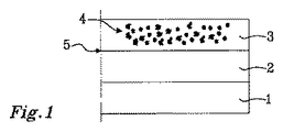
図1は、支持体1、可溶性マトリックス2、粘性材料を含むマトリックス3、および粒子4を含む構造を示す。可溶性マトリックス2、粘性材料を含むマトリックス3および粒子4は、本明細書に記載されているとおりであってもよい。粒子4はマトリックス3内に含まれている。可溶性マトリックス2とマトリックス3とが混和しないため、あるいはそれらの混和が非常に限られているため、可溶性マトリックス2とマトリックス3との間に界面5が形成される。当該構造は、支持体1を可溶性マトリックス2で被覆し、任意でその後に乾燥することにより形成してもよい。その後、粒子4および粘性材料を含むマトリックス3を可溶性マトリックス2上に堆積させる。
FIG. 1 shows a structure comprising a
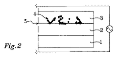
図2は、図1に示す構造への電場の印加を示す。電場を印加した際、粒子4は、可溶性マトリックス2とマトリックス3との界面5に配置された終端を含む少なくとも1つの粒子経路を形成する。粒子経路の少なくとも一部は、粒子のネットワークを形成してもよい。少なくとも1つの粒子経路の終端は、当該界面の平面に配置されていてもよく、かつ/または界面5を通ってマトリックス3から可溶性マトリックス2の中に突出していてもよい。当該粒子の目に見える移動が観察されなくなるまで電場を印加すると有利である。その整列が速すぎたり遅すぎたりして容易に観察できない場合、あるいは当該粒子の性質によりその場での整列の観察が難しくなる場合には、当該粒子の電場への応答を他の手段で確認するか、あるいは電場の除去後の観察により確認することができる。
FIG. 2 shows the application of an electric field to the structure shown in FIG. When an electric field is applied, the
電場の印加後に、界面5に終端を含む前記少なくとも1つの粒子経路を固定させるために、マトリックス3の粘性材料を固定させる。図3は、支持体1、可溶性マトリックス2、固定された粘性材料を含むマトリックス3、その少なくとも一部は終端を含む少なくとも1つの粒子経路の形態である粒子4および界面5を含む構造であり、マトリックス3の粘性材料を固定させた後の構造(resulting structure)を示す。当該粒子の少なくとも一部および/または少なくとも1つの粒子経路は粒子のネットワークを形成してもよい。前記少なくとも1つの粒子経路の終端は、マトリックス3の粘性材料内に埋め込まれるか、それによって覆われることなくマトリックス3の間の界面5の平面に位置しており、それにより可溶性マトリックス2をその後に除去した際、それらを露出させることができる。さらに、当該粒子の一部および/または前記少なくとも1つの粒子経路の終端および/または粒子のネットワークは、マトリックス3から可溶性マトリックス2の中に突出していてもよい。
After application of the electric field, the viscous material of the
図4は、支持体1を図3に示す構造から除去して得られる構造を示す。(支持体1を除去して)得られた構造は、可溶性マトリックス2、マトリックス3、その少なくとも一部は終端を含む少なくとも1つの粒子経路の形態である粒子4、および界面5を含む。前記少なくとも1つの粒子経路の終端は界面5に配置されている。当該終端は当該界面5の平面に位置していてもよく、かつ/またはマトリックス3から可溶性マトリックス3の中に突出していてもよい。
FIG. 4 shows the structure obtained by removing the
溶媒による洗い流し(rinsing)や洗浄といった化学的手段を適用して可溶性マトリックス2を曝露することにより、該可溶性マトリックス2を溶解し、これにより表面6において前記少なくとも1つの粒子経路の終端を露出させる。当該終端は表面6の平面にあってもよく、かつ/または表面6から突出していてもよい。このようにして(少なくとも1つの粒子経路の終端を露出させることで)得られた構造を図5に示す。前記少なくとも1つの粒子経路の露出された終端との接続を介して外部電気的手段をマトリックス3内の粒子のネットワークに接続させてもよい。
Exposing the
支持体1を図4に示す構造のマトリックス3上に堆積させてもよい。支持体1を、可溶性マトリックス2に面する側とは反対のマトリックス3の側面に堆積させてもよい。このようにして(支持体1を反対側のマトリックス3の側面に堆積させることにより)得られた構造を図6に示す。
The
次いで、可溶性マトリックス2を図6に示す構造から除去してもよい。溶媒による洗い流しまたは洗浄などの化学的手段によってこの除去を行ってもよく、それにより表面6において少なくとも1つの粒子経路の終端を露出させ、かつ/または、マトリックス3から突出させてもよい。このようにして(図6に示す構造から可溶性マトリックス2を除去して)得られた構造を図7に示す。
The
図8は、支持体1、可溶性マトリックス2、粘性材料を含むマトリックス3、その少なくとも一部は界面5および6のそれぞれに終端を含む少なくとも1つの粒子経路を形成するものである粒子4、さらなる可溶性マトリックス7、およびさらなる支持体8を含む構造を示す。粒子4を電場に曝して、該粒子4を界面5から界面6にわたって広がっている少なくとも1つの粒子経路の中に配置させる。少なくとも1つの粒子経路の終端は、前記界面の平面に配置されていてもよく、かつ/または、界面5および6を通ってマトリックス3から可溶性マトリックス2および7の中に突出していてもよい。このような構造は、前記少なくとも1つの粒子経路に電流を通すために、可溶性マトリックス2および7を除去して、外部の電気的手段を前記(粒子経路の)終端に接続させて、電流を通すことを可能とするものである。
FIG. 8 shows
図9は、支持体1、可溶性マトリックス2、粘性材料を含むマトリックス3、粒子4、さらなる可溶性マトリックス7、およびさらなる支持体8を含む構造を示す。マトリックス3内に含まれている粒子4の少なくとも一部は、マトリックス3の厚さ9よりも大きい長さ寸法を有する。
FIG. 9 shows a
図10は、図9に示す構造への電場の印加を示す。電場を印加した際、粒子4は電場によって配置および/または回転され、界面5および6のそれぞれに終端を含む少なくとも1つの粒子経路を形成する。当然のことながら本実施形態では、前記少なくとも1つの粒子経路は単一粒子を含む。少なくとも1つの粒子経路の終端は、界面5および6を通ってマトリックス3から可溶性マトリックス2および7の中に突出している。あるいは、少なくとも1つの粒子経路は、前記界面の平面に配置されていてもよい。この構造により可溶性マトリックス2および7の除去を可能にし、外部の電気的手段を前記終端に接続させてもよく、これにより前記少なくとも1つの粒子経路に電流を通すことができる。
FIG. 10 shows the application of an electric field to the structure shown in FIG. When an electric field is applied, the
以下の非限定的な実施例により、本発明をさらに説明する。 The invention is further illustrated by the following non-limiting examples.
<実施例1>
Dupont Teijin社から購入したポリエチレンテレフタレート(PET)基板Melinex 453の両側のうちの一方にコロナ処理を施した。次いで、Du Pont社から購入した0.2(重量)%のポリエチレングリコールp−(1,1,3,3−テトラメチルブチル)−フェニルエーテル(Triton X100)を含む50/40 Elvanol(PVA)の1重量%水溶液の形態のポリビニルアルコール(PVA)を、定量被覆用ロッド塗布装置を用いて、コロナ処理を施したPET基板の片側に薄膜として塗布した。水を除去して薄膜を硬化させるために被覆した薄膜を対流オーブンで乾燥して、PET基板上に0.15μm〜0.60μmのPVA被覆厚を得た。
Example 1
One of the two sides of a polyethylene terephthalate (PET) substrate Melinex 453 purchased from Dupont Teijin was subjected to corona treatment. Then, of 50/40 Elvanol (PVA) containing 0.2% (by weight) of polyethylene glycol p- (1,1,3,3-tetramethylbutyl) -phenylether (Triton X100) purchased from Du Pont Polyvinyl alcohol (PVA) in the form of a 1% by weight aqueous solution was applied as a thin film on one side of the corona-treated PET substrate using a quantitative coating rod coater. The coated film was dried in a convection oven to remove water and cure the film, to obtain a PVA coating thickness of 0.15 μm to 0.60 μm on a PET substrate.
Sigma−Aldrich社から購入した2〜3.5μmの大きさおよび0.5体積%の濃度を有する銀粒子を、Dymax社から購入したUV硬化型接着剤Dymax 3094と混合した。得られた接着剤混合物をロッド塗布装置を用いてPVA被覆上に薄膜として被覆した。これらのマトリックスポリマーの不相容性およびそれらの相対粘度により、これらの材料は混合しなかった。これらの層はその層間に画定された界面により分離していた。粒子を多く含む接着剤層の厚さは約80μmであった。 Silver particles having a size of 2 to 3.5 μm and a concentration of 0.5% by volume purchased from Sigma-Aldrich were mixed with a UV curable adhesive Dymax 3094 purchased from Dymax. The resulting adhesive mixture was coated as a thin film on a PVA coating using a rod coater. Due to the incompatibility of these matrix polymers and their relative viscosities, these materials did not mix. The layers were separated by an interface defined between the layers. The thickness of the particle-rich adhesive layer was about 80 μm.
PVAおよび接着剤が電極に面しない状態で、PVA被覆および粒子/接着剤被覆を有するPET基板を電極の上に置いた。350V(ボルト)の電圧および10kHz(キロヘルツ)の周波数を有する櫛形電極設計を用いて電場を生成した。この電場により銀粒子内に電気双極子を誘起し、それらを最も高い電場勾配を有する領域に向かって、すなわち接着剤層を通ってPVAと接着剤との界面に向かって移動させた。さらに、銀粒子は双極子間相互作用により互いに相互作用し、こうして、最も高いネットワーク密度が接着剤とPVAとの界面の近くにある状態で接続された連続的なネットワークを形成する。接続された粒子の一部は接着剤の表面に残存し、接続された粒子の一部は界面に貫入した。両状況下において、接着剤ポリマーは銀粒子を覆ったり遮蔽したりしない。拡大した状態で当該粒子が移動しているように見えず、かつ接続されているように見えた場合、粒子のネットワークを固定させてさらなる移動を防止し、これにより当該粒子の接続されたネットワークの連続性を確保する。ネットワークの接続性のための粒子の固定化は、当該接着剤をUV光源に曝露する(架橋させる)ことにより達成され、UV光源により、接着剤を硬化させて、かつ当該マトリックスの粘度を増加させることにより、当該粒子が固定される。これにより、固定されなければ当該粒子ネットワークを破壊する可能性がある粒子の移動すなわちドリフトが抑制される。集合した導電性粒子を含む接着剤マトリックスを、350〜600nmのUVスペクトル出力を供給する200W(ワット)の水銀ショートアークランプを備えたOmnicure S2000を用いてUV硬化させた。 With the PVA and the adhesive not facing the electrode, a PET substrate with a PVA coating and a particle / adhesive coating was placed on the electrode. An electric field was generated using a comb electrode design having a voltage of 350 V (volts) and a frequency of 10 kHz (kilohertz). The electric field induced electric dipoles in the silver particles and moved them towards the region with the highest electric field gradient, ie through the adhesive layer towards the interface of PVA and the adhesive. In addition, the silver particles interact with each other through dipolar interactions, thus forming a continuous network connected with the highest network density near the adhesive-PVA interface. Some of the connected particles remained on the surface of the adhesive, and some of the connected particles penetrated the interface. Under both circumstances, the adhesive polymer does not cover or shield the silver particles. If the particles do not appear to move and appear to be connected in the expanded state, the particle network is fixed to prevent further movement, thereby allowing the particles to connect to the connected network. Ensure continuity. Immobilization of particles for network connectivity is achieved by exposing (crosslinking) the adhesive to a UV light source, curing the adhesive by the UV light source and increasing the viscosity of the matrix The particles are thereby fixed. This suppresses migration or drift of particles that can otherwise destroy the particle network. The adhesive matrix containing the assembled conductive particles was UV cured using an Omnicure S2000 equipped with a 200 W (watt) mercury short arc lamp providing a UV spectral output of 350-600 nm.
PVAおよび位置合わせさせた粒子を多く含む接着剤構造からPETを手で剥離することにより、この薄膜を分離した。これにより、最も高い組織化されたネットワーク密度がその界面において生じる、PVA層と、銀粒子の連続的な接続されたネットワークを含む接着剤層とからなる2層構造を得た。 The film was separated by manually peeling the PET from the adhesive structure, which is rich in PVA and aligned particles. This resulted in a two-layer structure consisting of a PVA layer and an adhesive layer comprising a continuous connected network of silver particles, where the highest organized network density occurs at the interface.
第2のPET支持膜を、2層構造の露出された接着剤層(PVA被覆に面する側とは反対側)に貼り付けた。その後、PVA被覆を水で洗い流して、粒子のネットワークの一部およびネットワークノードを接着剤被覆の界面で露出させた。PVAを完全に除去したら、強制熱風手持ち式加熱器を用いて当該薄膜を乾燥した。 A second PET support film was attached to the exposed adhesive layer of the two-layer structure (opposite to the side facing the PVA coating). The PVA coating was then flushed with water to expose a portion of the network of particles and network nodes at the interface of the adhesive coating. Once the PVA was completely removed, the thin film was dried using a forced hot air hand-held heater.
上記のように洗浄および乾燥した後に得られた構造を、走査電子顕微鏡(SEM)を用いる分析およびX線元素分析に供した。20kVの電界電圧を用いて1500倍の拡大でSEM分析を完了させ、X線元素分析は約0.5〜1.0μmの侵入表面を生じる電子ビーム体積を使用した。その結果から、銀粒子のネットワークの形成およびポリマー表面におけるその露出を確認した。 The structures obtained after washing and drying as described above were subjected to analysis using scanning electron microscopy (SEM) and X-ray elemental analysis. The SEM analysis was completed at 1500 × magnification with a field voltage of 20 kV and X-ray elemental analysis used an electron beam volume that yielded an interstitial surface of about 0.5-1.0 μm. The results confirmed the formation of a network of silver particles and its exposure at the polymer surface.
<実施例2>
Du Pont社から購入した50/40 Elvanol(PVA)の2重量%水溶液の形態のPVAを、定量被覆用ロッド塗布装置を用いてGoodfellow社から購入したPET基板上に50μmの厚さの薄膜として塗布した。水を除去して薄膜を硬化させるために、被覆した薄膜を対流オーブンで乾燥し、PET基板上に約1μmのPVA被覆厚を得た。次いで、PVA被覆を有するPET基板を小片に切断し、この基板の2つの小片を、PVAが電極に面しない状態で2つの別個の平面透明電極上に置いた。
Example 2
Apply PVA in the form of a 2% by weight aqueous solution of 50/40 Elvanol (PVA) purchased from DuPont as a 50 μm thick film on a PET substrate purchased from Goodfellow using a rod coater for quantitative coating did. To remove the water and cure the film, the coated film was dried in a convection oven to obtain a PVA coating thickness of about 1 μm on a PET substrate. The PET substrate with the PVA coating was then cut into pieces, and two pieces of the substrate were placed on two separate planar transparent electrodes with the PVA not facing the electrode.
Sultzer Metco社から購入した25〜90μmの大きさおよび0.5体積%の濃度を有するニッケルグラファイト粒子を、Edmund Optics社から購入したUV硬化接着剤Norland NOA81と混合した。得られた接着剤混合物を、木製塗布棒を用いて電極のうちの一方の上にあるPVA被覆した基板上に液滴として堆積させた。150μmの規定の厚さを有するスペーサを、接着剤混合物から離した状態で前記電極の上に置いた。次いで、もう一方の電極をPVA被覆が接着剤に面した状態で混合物の上に押し付け、混合物の液滴を圧縮してスペーサの厚さと等しい制御された厚さを有する円形の薄膜にした。 Nickel graphite particles having a size of 25-90 μm and a concentration of 0.5% by volume purchased from Sultzer Metco were mixed with a UV curing adhesive Norland NOA 81 purchased from Edmund Optics. The resulting adhesive mixture was deposited as droplets on a PVA-coated substrate on one of the electrodes using a wooden applicator bar. A spacer with a defined thickness of 150 μm was placed on the electrode apart from the adhesive mixture. The other electrode was then pressed onto the mixture with the PVA coating facing the adhesive and the droplets of the mixture were compressed into a circular thin film with a controlled thickness equal to the thickness of the spacer.
PVAと接着剤との不相容性およびそれらの相対粘度により、これらの材料は混合しなかった。得られたサンドイッチ構造は、一端から他端に向かって電極、基板、PVA、粒子を多く含む接着剤混合物、PVA、基板、電極を含む一連の層で構成されていた。全ての層は、これらの層の間に画定された界面によって分離されていた。 Due to the incompatibility of the PVA with the adhesive and their relative viscosities, these materials did not mix. The obtained sandwich structure was composed of a series of layers including an electrode, a substrate, PVA, an adhesive mixture containing a large amount of particles, PVA, a substrate, and an electrode from one end to the other end. All layers were separated by an interface defined between these layers.
350Vの電圧および10kHzの周波数を印加して電極の間に電場を設定した。電場により銀粒子中に電気双極子を誘起させ、これらの粒子を集合および接続した鎖状に整列させる。この粒子の鎖は接着剤混合物の平面に対して垂直に延在し、当該混合物の片側にあるPVAと接着剤との界面間の隙間を跨ぐ積み重ねられた粒子の列を形成する。電極の大きさが限られているため、それらの間の隙間の中心よりも電極に近い箇所で電場は若干強くなる。これによりニッケルグラファイト粒子上に誘電泳動力が生じ、これが当該粒子鎖の端部を接着剤とPVAとの界面に引き寄せる。接続された粒子の一部は当該接着剤の表面に残存し、一部の接続された粒子は当該界面に貫入した。どちらの状況下においても、接着剤ポリマーは、PVAと接着剤との界面においてニッケルグラファイト粒子を覆ったり遮蔽したりしない。 An electric field was set between the electrodes by applying a voltage of 350 V and a frequency of 10 kHz. An electric field induces electric dipoles in the silver particles to align the particles in an assembled and connected chain. The chains of particles extend perpendicular to the plane of the adhesive mixture to form an array of stacked particles across the gap between the PVA and adhesive interface on one side of the mixture. Due to the limited size of the electrodes, the electric field is slightly stronger at points closer to the electrodes than the center of the gap between them. This creates a dielectrophoretic force on the nickel graphite particles which draws the end of the particle chain to the interface between the adhesive and the PVA. Some of the connected particles remained on the surface of the adhesive and some connected particles penetrated the interface. Under both circumstances, the adhesive polymer does not cover or shield the nickel-graphite particles at the PVA-adhesive interface.
1分後、拡大した状態で見た際に当該粒子がさらなる移動を示さなった場合には、粒子のネットワークを固定させてさらなる移動を防止し、かつUV光源を用いて当該接着剤を硬化させる(架橋させる)ことにより、当該粒子の接続されたネットワークの連続性を確保した。UV光を透明電極、基板およびPVAを通して導き、サンドイッチ構造の中心で当該接着剤を透過および硬化させた。整列された導電性粒子を有する接着剤をUV光に曝露して当該接着剤を硬化させ、当該マトリックスの粘度を増加させ、それにより当該粒子の移動を阻止する。整列および接続された粒子鎖を含むマトリックス(接着剤)を、Dymax BlueWave200スポットライトシステムを用いてUV硬化させた。 After 1 minute, if the particles show no further movement when viewed in an expanded state, fix the particle network to prevent further movement and cure the adhesive using a UV light source By crosslinking (crosslinking), the continuity of the connected network of the particles was secured. UV light was directed through the transparent electrode, the substrate and the PVA to transmit and cure the adhesive at the center of the sandwich structure. Adhesives with aligned conductive particles are exposed to UV light to cure the adhesive and increase the viscosity of the matrix, thereby preventing migration of the particles. The matrix (adhesive) containing aligned and connected particle chains was UV cured using a Dymax BlueWave 200 spotlight system.
最初に電極をPETから手で分離し、次いで、PETをPVAおよび整列された粒子を多く含む接着剤構造から剥離して、当該薄膜を分離した。これにより、PVA層と、層法線に平行に整列されたニッケルグラファイト粒子の接続された連続的なネットワークを有する接着剤層と、第1のPVA層の反対側にあるPVA層とを含む3層構造を得た。 The thin film was separated by first manually separating the electrode from the PET and then peeling the PET from the adhesive structure rich in PVA and aligned particles. This includes an adhesive layer with a PVA layer, a connected continuous network of nickel-graphite particles aligned parallel to the layer normal, and a PVA layer on the opposite side of the first PVA layer 3 I got a layered structure.
その後、PVA被覆を水で洗い流して、接着剤層の両側の界面でネットワークノードを露出させた。PVAを完全に除去したら、当該薄膜を周囲条件で15分間空気乾燥させた。 The PVA coating was then rinsed with water to expose the network node at the interface on both sides of the adhesive layer. Once the PVA was completely removed, the film was allowed to air dry at ambient conditions for 15 minutes.
上記のように洗浄および乾燥した後、当該層を、それぞれが約1平方センチメートルの表面積を有する2枚の銅の間に挟んで銅片の間の抵抗性をマルチメータで測定することにより接着剤層の導電性を確認した。測定した抵抗性は10Ω(オーム)のオーダであった。 After washing and drying as described above, the adhesive layer is measured by interposing the layer between two pieces of copper, each having a surface area of about 1 square centimeter, and measuring the resistance between the pieces of copper with a multimeter. The conductivity of the The measured resistance was on the order of 10 ohms (ohms).
1 支持体
2 可溶性マトリックス
3 粘性材料を含むマトリックス
4 粒子
5 界面
6 界面(又は表面)
7 さらなる可溶性マトリックス
8 さらなる支持体
9 (マトリックス3の)厚さ
1
7 additional
Claims (12)
前記水溶性もしくは非水溶性マトリックス(2)、または、前記粘性材料および粒子を含むマトリックス(3)を、前記水溶性もしくは非水溶性マトリックス(2)、または、前記粘性材料および粒子を含むマトリックス(3)に面した少なくとも1つの側面を含む支持体(1)と接触させる工程と、
前記水溶性もしくは非水溶性マトリックス(2)を前記粘性材料および粒子を含むマトリックス(3)と接触させた状態で配置し、それにより前記水溶性もしくは非水溶性マトリックスと前記粘性材料および粒子を含むマトリックスとの間に少なくとも1つの界面(5)を含む構造を得る工程と、
前記構造内の粒子を電場および/または磁場に曝し、それにより前記粒子を、前記水溶性もしくは非水溶性マトリックスと前記粘性材料および粒子を含むマトリックスとの間の少なくとも1つの界面(5)に終端を含む少なくとも1つの粒子経路に形成する工程と、
前記少なくとも1つの粒子経路を固定させるために前記粘性材料を固定させる工程と
を含み、
前記終端は前記水溶性もしくは非水溶性マトリックスを溶解して除去したときに露出されることを特徴とする方法。 A method of disposing particles at the interface of a water soluble or water insoluble matrix (2) and a matrix (3) comprising a viscous material and particles,
The water-soluble or water-insoluble matrix (2) , or the matrix (3) containing the viscous material and the particles, the water-soluble or water-insoluble matrix (2) , or the matrix containing the viscous material and the particles ( 3) contacting with a support (1) comprising at least one side facing the 3)
The water-soluble or water-insoluble matrix (2) is arranged in contact with the matrix (3) comprising the viscous material and particles, whereby it comprises the water-soluble or water-insoluble matrix and the viscous material and particles Obtaining a structure comprising at least one interface (5) with the matrix,
The particles in the structure are exposed to an electric and / or magnetic field, thereby terminating the particles at at least one interface (5) between the water-soluble or water-insoluble matrix and the matrix comprising the viscous material and particles. Forming in at least one particle path comprising
Immobilizing the viscous material to immobilize the at least one particle path;
Said termination is exposed when the water soluble or water insoluble matrix is dissolved and removed.
A method according to any one of the preceding claims, wherein the at least one particle path is a conductive particle path.
Applications Claiming Priority (3)
| Application Number | Priority Date | Filing Date | Title |
|---|---|---|---|
| EP14169206.1A EP2947662A1 (en) | 2014-05-21 | 2014-05-21 | A method for arranging particles at an interface |
| EP14169206.1 | 2014-05-21 | ||
| PCT/EP2015/061244 WO2015177275A1 (en) | 2014-05-21 | 2015-05-21 | A method for forming an article comprising a pathway of particles wherein a termination of the pathway of particles is exposed |
Publications (3)
| Publication Number | Publication Date |
|---|---|
| JP2017518611A JP2017518611A (en) | 2017-07-06 |
| JP2017518611A5 JP2017518611A5 (en) | 2018-05-24 |
| JP6518698B2 true JP6518698B2 (en) | 2019-05-22 |
Family
ID=50735959
Family Applications (1)
| Application Number | Title | Priority Date | Filing Date |
|---|---|---|---|
| JP2016568555A Active JP6518698B2 (en) | 2014-05-21 | 2015-05-21 | Method of forming an article comprising a particle path with an exposed end |
Country Status (6)
| Country | Link |
|---|---|
| US (2) | US20170080609A1 (en) |
| EP (2) | EP2947662A1 (en) |
| JP (1) | JP6518698B2 (en) |
| KR (1) | KR102337625B1 (en) |
| CN (1) | CN106459697A (en) |
| WO (1) | WO2015177275A1 (en) |
Families Citing this family (5)
| Publication number | Priority date | Publication date | Assignee | Title |
|---|---|---|---|---|
| NO20170513A1 (en) * | 2017-03-29 | 2018-06-04 | Condalign As | A method for forming av body comprising at least one through-going passage |
| KR20200075098A (en) | 2018-12-11 | 2020-06-26 | 현대자동차주식회사 | System of controlling the high voltage battery output for a eco-friendly vehicle |
| WO2021012242A1 (en) * | 2019-07-25 | 2021-01-28 | China Triumph International Engineering Co., Ltd. | Method to manufacture an inorganic thin film solar cell device and an inorganic thin film solar cell device |
| KR20210031275A (en) | 2019-09-11 | 2021-03-19 | 현대자동차주식회사 | Control method for cylinder deactivation and engine of which the same is applied |
| KR102278410B1 (en) | 2020-11-17 | 2021-07-19 | 주식회사 클레스앤피 | High-performance deep learning finger vein authentication system and metod that can simultaneously measure personal health status |
Family Cites Families (26)
| Publication number | Priority date | Publication date | Assignee | Title |
|---|---|---|---|---|
| USRE21762E (en) | 1941-04-08 | Adhesive sheeting | ||
| JPS6155809A (en) * | 1984-08-27 | 1986-03-20 | 日立化成工業株式会社 | Conductive adhesive film wind |
| US5045249A (en) * | 1986-12-04 | 1991-09-03 | At&T Bell Laboratories | Electrical interconnection by a composite medium |
| US4923739A (en) * | 1987-07-30 | 1990-05-08 | American Telephone And Telegraph Company | Composite electrical interconnection medium comprising a conductive network, and article, assembly, and method |
| US4820376A (en) * | 1987-11-05 | 1989-04-11 | American Telephone And Telegraph Company At&T Bell Laboratories | Fabrication of CPI layers |
| JPH07230840A (en) * | 1994-02-17 | 1995-08-29 | Hitachi Chem Co Ltd | Connecting member and electrode connecting structure using the same |
| US5509815A (en) | 1994-06-08 | 1996-04-23 | At&T Corp. | Solder medium for circuit interconnection |
| JPH08273442A (en) * | 1995-03-22 | 1996-10-18 | Whitaker Corp:The | Anisotropic electric conduction film and its preparation |
| US5975922A (en) | 1998-03-09 | 1999-11-02 | Lucent Technologies Inc. | Device containing directionally conductive composite medium |
| US6322713B1 (en) | 1999-07-15 | 2001-11-27 | Agere Systems Guardian Corp. | Nanoscale conductive connectors and method for making same |
| JP3928389B2 (en) * | 2001-08-31 | 2007-06-13 | Jsr株式会社 | Anisotropic conductive sheet and manufacturing method thereof |
| JP2003187885A (en) * | 2001-12-20 | 2003-07-04 | Sony Corp | Anisotropic conductive film, method for manufacturing the same, and electronic component mounted body |
| JP2004047268A (en) * | 2002-07-11 | 2004-02-12 | Shin Etsu Polymer Co Ltd | Insulation displacement connector |
| JP2005116291A (en) * | 2003-10-07 | 2005-04-28 | Sumitomo Electric Ind Ltd | Anisotropic conductive film and its forming method |
| KR100601341B1 (en) * | 2004-06-23 | 2006-07-14 | 엘에스전선 주식회사 | Anisotropic conductive adhesive and the adhesive flim using thereof |
| US8057889B2 (en) | 2007-05-21 | 2011-11-15 | Corning Incorporated | Method for producing anisoptropic bulk materials |
| US20110155946A1 (en) * | 2008-08-05 | 2011-06-30 | World Properties, Inc. | Conductive Polymer Foams, Method of Manufacture, and Articles Thereof |
| KR100976548B1 (en) | 2008-09-12 | 2010-08-17 | 김희구 | pad for herb remedy and method for manufacturing thereof |
| US10090076B2 (en) * | 2009-06-22 | 2018-10-02 | Condalign As | Anisotropic conductive polymer material |
| NO333507B1 (en) * | 2009-06-22 | 2013-06-24 | Condalign As | A method of making an anisotropic conductive layer and an object produced therefrom |
| WO2011082058A1 (en) * | 2009-12-29 | 2011-07-07 | Rogers Corporation | Conductive polymer foams, method of manufacture, and uses thereof |
| EP3598122B1 (en) * | 2010-12-08 | 2022-10-12 | Condalign AS | Sensor with conductive pathways formed from conductive particles |
| CN103517958A (en) * | 2010-12-15 | 2014-01-15 | 康达利恩股份公司 | Method for forming uv-curable conductive compositions and a domposition thus formed |
| KR101263327B1 (en) | 2011-05-06 | 2013-05-16 | 광주과학기술원 | Film member, film target for laser-driven ion acceleration and manufacturing methods thereof |
| NO20120740A1 (en) * | 2012-06-25 | 2013-12-26 | Inst Energiteknik | A method of forming a body with a particle structure fixed in a matrix material |
| NO20120739A1 (en) * | 2012-06-25 | 2013-12-26 | Inst Energiteknik | A method of forming a body with a particle structure fixed in a matrix material |
-
2014
- 2014-05-21 EP EP14169206.1A patent/EP2947662A1/en not_active Withdrawn
-
2015
- 2015-05-21 CN CN201580030329.5A patent/CN106459697A/en active Pending
- 2015-05-21 KR KR1020167034422A patent/KR102337625B1/en active IP Right Grant
- 2015-05-21 JP JP2016568555A patent/JP6518698B2/en active Active
- 2015-05-21 WO PCT/EP2015/061244 patent/WO2015177275A1/en active Application Filing
- 2015-05-21 EP EP15724283.5A patent/EP3146530B1/en active Active
- 2015-05-21 US US15/312,485 patent/US20170080609A1/en not_active Abandoned
-
2021
- 2021-07-09 US US17/371,214 patent/US11618186B2/en active Active
Also Published As
| Publication number | Publication date |
|---|---|
| US11618186B2 (en) | 2023-04-04 |
| WO2015177275A1 (en) | 2015-11-26 |
| EP3146530A1 (en) | 2017-03-29 |
| CN106459697A (en) | 2017-02-22 |
| US20170080609A1 (en) | 2017-03-23 |
| KR20170012304A (en) | 2017-02-02 |
| EP2947662A1 (en) | 2015-11-25 |
| JP2017518611A (en) | 2017-07-06 |
| US20220134609A1 (en) | 2022-05-05 |
| EP3146530B1 (en) | 2021-04-21 |
| KR102337625B1 (en) | 2021-12-09 |
Similar Documents
| Publication | Publication Date | Title |
|---|---|---|
| US11618186B2 (en) | Method for forming an article comprising a pathway of particles wherein a termination of the pathway of particles exposed | |
| JP5730240B2 (en) | Capacitance sensor sheet manufacturing method and capacitance sensor sheet | |
| Song et al. | Photoenhanced patterning of metal nanowire networks for fabrication of ultraflexible transparent devices | |
| KR101595895B1 (en) | Film for transparent electrode with welded silver nanowire by light sintering, Dispersion liquid for welding silver nanowire, and Welding method of silver nanowire by light sintering | |
| US9899121B2 (en) | Systems and methods for providing overcharge protection in capacitive coupled biomedical electrodes | |
| TWI611433B (en) | Production method of conductive pattern | |
| JP5255036B2 (en) | Joining method | |
| CN105110323A (en) | Preparation method for graphene oxide freestanding ultrathin film | |
| JP2011136191A (en) | Method for generating electrically contactable area on dopedpolymer and formed body produced by the method | |
| US9257258B2 (en) | Method of making transmission electron microscope micro-grid | |
| JP2017518611A5 (en) | ||
| TWI499439B (en) | Electrode device for use in iontophoresis | |
| US9406481B2 (en) | Transmission electron microscope micro-grid | |
| WO2016087575A1 (en) | High capacity redox electrodes and their use in cell lysis | |
| WO2005050745A1 (en) | Columnar electric device and its manufacturing method | |
| JP2017512378A5 (en) | ||
| US10177367B2 (en) | Method for producing surface discharge electrodes and semifinished product for carrying out the method | |
| KR101606080B1 (en) | Film capable of self-healing for electrical conductivy using light, fabrication method for the same, and application for the same | |
| Youn et al. | Arbitrary alignment-angle control method of electrospun fibers: potential for a stretchable electrode material | |
| KR102035603B1 (en) | Composite conductive substrate and manufacturing method thereof | |
| CN108021970B (en) | Transparent invisible RFID label material and preparation method thereof | |
| US20170294653A1 (en) | Grid electrode for polar solvent-based hydro-pyroelectrodynamic electrical energy storage device | |
| JP2012085496A (en) | Exposure structure of conductor wires for collective conductor, and method of producing the same | |
| KR101332776B1 (en) | Method for forming conductive layer electrically connecting substrate and structure disposed on the substrate, and layered structure comprising conductive layer | |
| TW200838379A (en) | Method of manufacturing stacked electronic device |
Legal Events
| Date | Code | Title | Description |
|---|---|---|---|
| A521 | Request for written amendment filed |
Free format text: JAPANESE INTERMEDIATE CODE: A523 Effective date: 20180405 |
|
| A621 | Written request for application examination |
Free format text: JAPANESE INTERMEDIATE CODE: A621 Effective date: 20180405 |
|
| A977 | Report on retrieval |
Free format text: JAPANESE INTERMEDIATE CODE: A971007 Effective date: 20190313 |
|
| TRDD | Decision of grant or rejection written | ||
| A01 | Written decision to grant a patent or to grant a registration (utility model) |
Free format text: JAPANESE INTERMEDIATE CODE: A01 Effective date: 20190402 |
|
| A61 | First payment of annual fees (during grant procedure) |
Free format text: JAPANESE INTERMEDIATE CODE: A61 Effective date: 20190422 |
|
| R150 | Certificate of patent or registration of utility model |
Ref document number: 6518698 Country of ref document: JP Free format text: JAPANESE INTERMEDIATE CODE: R150 |
|
| R250 | Receipt of annual fees |
Free format text: JAPANESE INTERMEDIATE CODE: R250 |
|
| R250 | Receipt of annual fees |
Free format text: JAPANESE INTERMEDIATE CODE: R250 |