JP6516626B2 - Microphone device - Google Patents
Microphone device Download PDFInfo
- Publication number
- JP6516626B2 JP6516626B2 JP2015160636A JP2015160636A JP6516626B2 JP 6516626 B2 JP6516626 B2 JP 6516626B2 JP 2015160636 A JP2015160636 A JP 2015160636A JP 2015160636 A JP2015160636 A JP 2015160636A JP 6516626 B2 JP6516626 B2 JP 6516626B2
- Authority
- JP
- Japan
- Prior art keywords
- microphone
- unit
- mount member
- shock mount
- cable
- Prior art date
- Legal status (The legal status is an assumption and is not a legal conclusion. Google has not performed a legal analysis and makes no representation as to the accuracy of the status listed.)
- Expired - Fee Related
Links
Images

Classifications
-
- H—ELECTRICITY
- H04—ELECTRIC COMMUNICATION TECHNIQUE
- H04R—LOUDSPEAKERS, MICROPHONES, GRAMOPHONE PICK-UPS OR LIKE ACOUSTIC ELECTROMECHANICAL TRANSDUCERS; ELECTRIC HEARING AIDS; PUBLIC ADDRESS SYSTEMS
- H04R1/00—Details of transducers, loudspeakers or microphones
- H04R1/20—Arrangements for obtaining desired frequency or directional characteristics
- H04R1/22—Arrangements for obtaining desired frequency or directional characteristics for obtaining desired frequency characteristic only
- H04R1/28—Transducer mountings or enclosures modified by provision of mechanical or acoustic impedances, e.g. resonator, damping means
- H04R1/2869—Reduction of undesired resonances, i.e. standing waves within enclosure, or of undesired vibrations, i.e. of the enclosure itself
- H04R1/2876—Reduction of undesired resonances, i.e. standing waves within enclosure, or of undesired vibrations, i.e. of the enclosure itself by means of damping material, e.g. as cladding
-
- H—ELECTRICITY
- H04—ELECTRIC COMMUNICATION TECHNIQUE
- H04R—LOUDSPEAKERS, MICROPHONES, GRAMOPHONE PICK-UPS OR LIKE ACOUSTIC ELECTROMECHANICAL TRANSDUCERS; ELECTRIC HEARING AIDS; PUBLIC ADDRESS SYSTEMS
- H04R1/00—Details of transducers, loudspeakers or microphones
- H04R1/06—Arranging circuit leads; Relieving strain on circuit leads
-
- H—ELECTRICITY
- H04—ELECTRIC COMMUNICATION TECHNIQUE
- H04R—LOUDSPEAKERS, MICROPHONES, GRAMOPHONE PICK-UPS OR LIKE ACOUSTIC ELECTROMECHANICAL TRANSDUCERS; ELECTRIC HEARING AIDS; PUBLIC ADDRESS SYSTEMS
- H04R1/00—Details of transducers, loudspeakers or microphones
- H04R1/02—Casings; Cabinets ; Supports therefor; Mountings therein
- H04R1/04—Structural association of microphone with electric circuitry therefor
Landscapes
- Physics & Mathematics (AREA)
- Engineering & Computer Science (AREA)
- Acoustics & Sound (AREA)
- Signal Processing (AREA)
- Health & Medical Sciences (AREA)
- Otolaryngology (AREA)
- Details Of Audible-Bandwidth Transducers (AREA)
- Electrostatic, Electromagnetic, Magneto- Strictive, And Variable-Resistance Transducers (AREA)
Description
この発明は、マイクロホンケース内にショックマウント部材を介してマイクロホンユニットを取り付けたマイクロホン装置に関し、特にマイクロホンユニットからの電気信号を導出するマイクケーブルの配置構成に工夫を施したマイクロホン装置に関する。 The present invention relates to a microphone device in which a microphone unit is mounted in a microphone case via a shock mount member, and more particularly to a microphone device in which arrangement of a microphone cable for deriving an electric signal from the microphone unit is devised.
例えばハンドヘルド型マイクロホンは、利用者がマイクロホンケースの胴部を直接把持することから、マイクロホンケース内のマイクロホンユニットに対して振動や加速度が加わる度合いが大きい。前記マイクロホンユニットに加わる振動や加速度は、タッチノイズやハンドリングノイズと称する振動雑音として生成される。 For example, in a hand-held type microphone, since the user directly grips the body portion of the microphone case, the degree to which vibration and acceleration are applied to the microphone unit in the microphone case is large. The vibration or acceleration applied to the microphone unit is generated as vibration noise called touch noise or handling noise.
そこで、この種のマイクロホン装置においては、前記した振動雑音の発生を防止するために、マイクロホンユニットを例えばゴム素材により形成したショックマウント部材を介してマイクロホンケース内に取り付けた構成が採用されており、これは特許文献1および2などに開示されている。
Therefore, in this type of microphone device, in order to prevent the generation of the above-described vibration noise, a configuration in which the microphone unit is attached to the inside of the microphone case via a shock mount member formed of, for example, a rubber material is adopted. This is disclosed in
前記マイクロホンユニットを支持するショックマウント部材は、マイクロホンユニットのサスペンションとして機能し固有の共振周波数を有している。したがってマイクロホンユニットがショックマウント部材と共に外部振動を受けて共振すると、これが大きな振動雑音となって出力されるので、前記共振周波数をマイクロホンユニットの収音帯域よりも低い、あるいは収音帯域内であっても目立たない低い帯域に設定する必要がある。
そのためには、サスペンションとして機能するショックマウント部材の材質として、より柔らかいものを選定する必要があり、これによりマイクロホンユニットはマイクロホンケース内において大きな可動範囲をもって動くことになる。
The shock mount member supporting the microphone unit functions as a suspension of the microphone unit and has a unique resonance frequency. Therefore, when the microphone unit receives an external vibration with the shock mount member and resonates, this is output as a large vibration noise, so that the resonance frequency is lower than the sound collection band of the microphone unit or within the sound collection band You need to set it to a low band that is not noticeable.
For that purpose, it is necessary to select a softer shock mount as a material of the shock mount member which functions as a suspension, whereby the microphone unit moves with a large movable range in the microphone case.
一方、ショックマウント部材により支持された前記マイクロホンユニットと、これを収容するマイクロホンケースに装着されたコネクタとの間には、マイクロホンユニット側からの電気信号を導出するマイクケーブルが接続されている。 On the other hand, a microphone cable for leading an electric signal from the microphone unit side is connected between the microphone unit supported by the shock mount member and a connector mounted on a microphone case for housing the microphone unit.
図7〜図10は、ショックマウント部材を備えた従来のマイクロホン装置における前記したマイクケーブルの配置構成を例示している。
なお、図7〜図10に示される従来のマイクロホン装置においては、後で説明する図1〜図6に示したこの発明に係る実施の形態と同一の機能を果たす部材が備えられており、それぞれ同一符号で示している。したがって各部の詳細な構成は、図1〜図6に基づいて後で説明する。
7 to 10 illustrate the arrangement of the microphone cable in a conventional microphone device provided with a shock mounting member.
The conventional microphone devices shown in FIGS. 7 to 10 are provided with members having the same functions as those of the embodiment according to the present invention shown in FIGS. 1 to 6, which will be described later. It shows with the same code. Therefore, the detailed configuration of each part will be described later based on FIGS. 1 to 6.
従来のマイクロホン装置におけるマイクケーブル45は、図7に例示したようにマイクロホンケース30のほぼ中央部に沿った空間内に、なるべく緩みのないほぼ直線状態で配置されて、マイクロホンユニット10側とコネクタ47との間を接続している。
この図7に示された構成によると、マイクケーブル45は、マイクロホンユニット10側とコネクタ47との間の空間部に、宙に浮いた状態で配置されるために、マイクロホンケース30側に受ける振動は、破線で模式的に示したように、コネクタ47からマイクケーブル45を介してマイクロホンユニット10側に伝達される。これにより、振動雑音が発生する。
The
According to the configuration shown in FIG. 7, the
前記マイクケーブル45を介した振動雑音の発生を阻止するためには、前記マイクケーブル45として、より細い線材を用いることが考えられる。
しかしながら、マイクロホン装置を落下させる等して、大きな衝撃が加わった場合には、マイクロホンユニット10側がショックマウント部材41,42を介して瞬時に大きく揺動する。これによって、マイクケーブル45に無理な張力が加わり、図8に示したようにマイクケーブル45が断線するという問題が発生する。
In order to prevent the generation of vibration noise through the
However, when a large impact is applied, for example, by dropping the microphone device, the
そこで、マイクロホンユニット10側とコネクタ47との間に接続されるマイクケーブル45に、図10に示すように十分な緩みを与えた状態にすると、前記したようにマイクロホン装置に大きな衝撃が加わった場合におけるマイクケーブル45の断線を防止させることができる。しかしながら、今度はマイクケーブル45が自由に振動し、マイクケーブル45の自由な振動が、図9に示すようにマイクロホンユニット10側に伝わり、これが振動雑音を発生させる要因になる。
すなわち、図9に示した両方向の矢印は、マイクケーブル45が自由に振動する様子を示しており、マイクケーブル45の振動がマイクロホンユニット10側に伝わる状況を破線で模式的に示している。
Then, if a sufficient looseness is given to the
That is, the arrows in both directions shown in FIG. 9 indicate how the
マイクロホンユニットをショックマウント部材を介してマイクロホンケース内で支持したマイクロホン装置においては、マイクロホンユニット側とコネクタとを接続するマイクケーブルは、図7〜図10に基づいて説明したように、それぞれの要因により振動雑音を発生させる問題を抱えている。また衝撃を受けた場合のマイクケーブルの断線等の問題も抱えている。 In the microphone device in which the microphone unit is supported in the microphone case via the shock mount member, the microphone cable connecting the microphone unit side and the connector is, as described with reference to FIGS. There is a problem of generating vibration noise. It also has problems such as microphone cable disconnection when it receives an impact.
そこで、この発明はマイクケーブルを介したマイクロホンユニット側への外部振動の伝達、マイクケーブル自身の振動によるマイクロホンユニット側への振動の伝達を効果的に阻止することができ、またたとえマイクロホンケースに大きな衝撃が加わった場合においても、マイクケーブルの断線を阻止することができるマイクロホン装置を提供することを課題とするものである。 Therefore, the present invention can effectively block the transmission of external vibration to the microphone unit side via the microphone cable and the transmission of vibration to the microphone unit side due to the vibration of the microphone cable itself, and the microphone case is large. An object of the present invention is to provide a microphone device capable of preventing disconnection of a microphone cable even when an impact is applied.
前記した課題を解決するためになされたこの発明に係るマイクロホン装置は、音波を受けて電気信号を出力するマイクロホンユニットと、弾性素材により形成したショックマウント部材を介して前記マイクロホンユニットを内部に支持したマイクロホンケースと、前記マイクロホンユニット側からの電気信号を、前記マイクロホンケースに取り付けた出力コネクタに供給するマイクケーブルとを備えたマイクロホン装置であって、前記マイクケーブルの一部が、前記ショックマウント部材に沿って、取り付けられていることを特徴とする。 The microphone device according to the present invention, which has been made to solve the above-mentioned problems, supports the microphone unit inside through a microphone unit that receives an acoustic wave and outputs an electric signal, and a shock mount member formed of an elastic material. A microphone device comprising: a microphone case; and a microphone cable for supplying an electrical signal from the microphone unit side to an output connector attached to the microphone case, wherein a part of the microphone cable is attached to the shock mount member. It is characterized by being attached along.
この場合、一つの好ましい形態においては、前記マイクケーブルの一部が、偏平状に形成された前記ショックマウント部材の一方の面と他方の面との間を、一往復以上蛇行した状態で取り付けられる。 In this case, in a preferred embodiment, a part of the microphone cable is attached in a meandering state between one side and the other side of the flat-shaped shock mount member for at least one reciprocation. .
そして、より好ましくは、前記マイクロホンユニットが、ユニット支持部の前端部に取り付けられ、前記ユニット支持部の軸方向の少なくとも前後二か所において、フロントショックマウント部材とリアショックマウント部材によって、前記マイクロホンユニットがユニット支持部と共に軸方向に揺動可能に前記マイクロホンケース内で支持され、前記出力コネクタに近いリアショックマウント部材に、前記マイクケーブルの一部が取り付けられた構成が採用される。 More preferably, the microphone unit is attached to the front end of the unit support portion, and the microphone unit is mounted by the front shock mount member and the rear shock mount member at at least two positions in the axial direction of the unit support portion. Is supported in the microphone case so as to be able to pivot in the axial direction together with the unit support portion, and a configuration in which a part of the microphone cable is attached to a rear shock mount member near the output connector is adopted.
一方、リアショックマウント部材は、望ましくは円環状に形成されて、周縁部が前記マイクロホンケースに取り付けられると共に、中央部において前記ユニット支持部を軸方向に揺動可能に支持し、かつリアショックマウント部材の前記円環状の面に沿って形成された複数個の貫通孔を利用して、前記マイクケーブルの一部が、偏平状に形成された前記ショックマウント部材の一方の面と他方の面との間を、一往復以上蛇行した状態で取り付けられる。 On the other hand, the rear shock mount member is desirably formed in an annular shape, and the peripheral edge portion is attached to the microphone case, and the unit support portion is axially pivotally supported at the central portion and rear shock mount A part of the microphone cable is formed by using a plurality of through holes formed along the annular surface of the member, and one side and the other side of the shock mount member formed in a flat shape. Between one and more than one reciprocation.
そして好ましくは、前記マイクロホンユニットとして、コンデンサマイクロホンユニットが用いられ、前記ユニット支持部におけるコンデンサマイクロホンユニットの直後に、当該コンデンサマイクロホンユニットの音声出力回路を含む回路基板が搭載され、前記マイクケーブルが前記回路基板と前記出力コネクタとの間に接続された構成が採用される。 Preferably, a condenser microphone unit is used as the microphone unit, a circuit board including an audio output circuit of the condenser microphone unit is mounted immediately after the condenser microphone unit in the unit support portion, and the microphone cable is the circuit A configuration connected between the substrate and the output connector is employed.
加えて、前記マイクケーブルとしては、複数本の各信号線を束ねた状態で、前記ショックマウント部材の一方の面と他方の面との間を、一往復以上蛇行した状態で取り付けた構成が採用される。 In addition, as the microphone cable, in a state in which a plurality of signal lines are bundled, a configuration is adopted in which one side of the shock mount member is attached in a meandering state between one side and the other side. Be done.
前記したこの発明に係るマイクロホン装置によると、マイクロホンユニット側からの電気信号を、出力コネクタに供給するマイクケーブルの一部が、弾性素材により形成したショックマウント部材に沿って、取り付けられた構成が採用される。
したがって、マイクケーブルの一部は例えばゴム素材により構成されたショックマウント部材に常に接しているので、マイクロホンケース側において受ける振動が、マイクケーブルを介してマイクロホンユニット側に直接伝達されるのを阻止することができる。これにより振動雑音の発生を効果的に抑制させることができる。
According to the above-described microphone device according to the present invention, a configuration in which a part of the microphone cable for supplying the output connector with the electric signal from the microphone unit side is attached along the shock mount member formed of an elastic material is adopted. Be done.
Therefore, since a part of the microphone cable is always in contact with the shock mount member made of, for example, a rubber material, the vibration received on the microphone case side is prevented from being directly transmitted to the microphone unit side via the microphone cable. be able to. Thereby, the generation of vibration noise can be effectively suppressed.
また、マイクケーブルの一部がショックマウント部材に接しているので、マイクケーブル自身において生ずる自由振動も抑制され、マイクケーブルの自由振動による振動雑音の発生も抑制させることができる。
そして、ショックマウント部材に沿ったマイクケーブルは、多少の緩みをもった状態で配置することができるので、マイクロホンケースに衝撃が加えられた場合に、ショックマウント部材の変形に追従してマイクケーブルも同様に変形する。これにより、マイクケーブルに過剰な張力を与える等のストレスが加わるのを効果的に防止できる。
In addition, since a part of the microphone cable is in contact with the shock mount member, free vibration generated in the microphone cable itself can be suppressed, and generation of vibration noise due to free vibration of the microphone cable can also be suppressed.
And since the microphone cable along the shock mount member can be arranged with some slack, when the shock is applied to the microphone case, the microphone cable also follows the deformation of the shock mount member. Transform in the same way. As a result, it is possible to effectively prevent the stress such as applying excessive tension to the microphone cable.
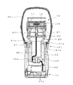
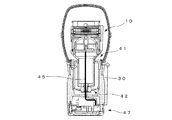
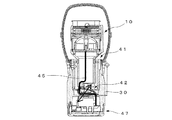
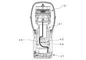
この発明に係るマイクロホン装置について、図に示す実施の形態に基づいて説明する。図1および図3は、この発明をコンデンサマイクロホンに適用した例を断面図で示しており、このコンデンサマイクロホンは、基本構成として、マイクロホンユニット10と、ユニット支持部20と、マイクロホンケース30とが備えられている。
A microphone device according to the present invention will be described based on an embodiment shown in the drawings. 1 and 3 show an example in which the present invention is applied to a condenser microphone in a cross-sectional view, and the condenser microphone comprises a
この実施の形態においては、前記マイクロホンユニット10には、第1エレメント11と第2エレメント12とが背中合わせに備えられている。
そして、マイクロホンユニット10は、金属性のユニットケース13によって、シリンダ状に形成されたユニット支持部20の前端部に取り付けられている。
In this embodiment, the
The
シリンダ状に形成されたユニット支持部20には、ドーム状に形成されたカバー21が取り付けられ、このカバー21の直後におけるユニット支持部20内には、前記マイクロホンユニット10の音声出力回路を含む回路基板22が搭載されている。
A dome-shaped
前記マイクロホンユニット10における第1エレメント11は、固定極に振動板が対峙したバックエレクトレット方式のコンデンサマイクロホンユニットを構成している。
一方、第2エレメント12は、固定極と振動板を備えているもののコンデンサマイクロホンは構成せずに、後部音響端子から入る音波に対して低音域をカットして、高音域のみを第1エレメント11の背面に伝えることで、実質的にハイパスフィルター(HPF)として機能させている。前記HPFの作用によりコンデンサマイクロホンの周波数特性において、特に低域の周波数特性を向上させている。
The
On the other hand, although the
ここで、音響端子とは、マイクロホンユニット10に対して実効的に音圧を与える空気の位置を示す。換言すれば、音響端子とはマイクロホンユニット10が備える振動板と同時に動く空気の中心位置である。マイクロホンユニット10は単一指向性であるので、音響端子は振動板の前部と後部にあり、後部音響端子は後部に存在する音響端子である。
そして、前記マイクロホンユニット10からの信号は、ドーム状カバー21の中央部に取り付けられた中継ロッド23を介して前記回路基板22に供給されるように構成されている。
Here, the acoustic terminal indicates the position of air that effectively provides sound pressure to the
A signal from the
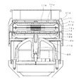
図2はマイクロホンユニット10を拡大した図であり、以下、具体的に説明する。第1エレメント11は、振動板11aと振動板11aに対峙した固定極11bを有するバックエレクトレット方式のコンデンサマイクロホンユニットを構成している。また、固定極11bは導電性を有する支持部材11cに支持され、振動板11aは振動板フレーム11dに支持されている。
FIG. 2 is an enlarged view of the
第2エレメント12も同様に振動板12a、固定極12b、支持部材12c、振動板フレーム12dを備えている。
二つの支持部材11c、12cは導電性を有する締結部材112により締結されて固定される。
Similarly, the
The two support members 11 c and 12 c are fastened and fixed by the conductive fastening member 112.
第1エレメント11の固定極11bは支持部材11cと電気的に接続され、第2エレメント12の振動板12aと固定極12bは支持部材12cと電気的に接続され、支持部材11c、12cは締結部材112、振動板フレーム12dと電気的に接続される。これにより、第1エレメント11によるコンデンサマイクロホンユニットと第2エレメント12によるハイパスフィルターが直列接続される。
また、振動板フレーム12dには導電性のねじ113が取り付けられ、ねじ113に中継ロッド23が電気的に接続される。
The fixed pole 11b of the
In addition, a conductive screw 113 is attached to the diaphragm frame 12d, and the
シリンダ状に形成されたユニット支持部20は、その前端部に前記したマイクロホンユニット10を搭載した状態で、ユニット支持部20の軸方向の前後二か所において、フロントショックマウント部材41と、リアショックマウント部材42を介して、マイクロホンケース30内に支持されている。
前記フロントショックマウント部材41およびリアショックマウント部材42は、それぞれゴム素材により構成されており、これにより前記マイクロホンユニット10はユニット支持部20と共に、前記マイクロホンケース30内で、軸方向に揺動可能に支持されている。
The
The front
前記フロントショックマウント部材41は、環状に形成された薄肉部41aの外側が円筒部41bになされ、マイクロホンケース30への取り付け部を構成している。また環状の薄肉部の内側は、短軸状の円筒部41cになされ、この円筒部41cが前記ユニット支持部20を囲撓するようにして支持している。
そして、フロントショックマウント部材41の外側の円筒部41bが、マイクロホンケース30内に同軸状に配置された円筒体43の外周面と、マイクロホンケース30の内壁面との間で挟持されることで、マイクロホンケース30内に取り付けられている。
The front
Then, the outer cylindrical portion 41 b of the front
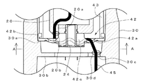
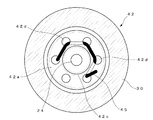
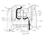
一方、リアショックマウント部材42は、図4〜図6に示されているように、円環状にして偏平状に形成された薄肉部42aが備えられ、この薄肉部42aの外周縁が、内側に向かって折り返されてマイクロホンケース30への取り付け部42bを構成している。また円環状の薄肉部42aの内側には、円筒部42cが一体に形成されており、この円筒部42cは、前記したユニット支持部20の下底部に軸方向に突出して取り付けられた中空軸体24を囲撓している。これにより、リアショックマウント部材42は、前記ユニット支持部20を、下底部において支持している。
On the other hand, as shown in FIGS. 4 to 6, the rear
そして、リアショックマウント部材42の外周縁に折り返された取り付け部42bは、マイクロホンケース30内に同軸状に配置された前記円筒体43の下端部に係止され、この係止部がマイクロホンケース30内に形成された内径を若干縮小する段部30aに当接することで取り付けられている。
なお、リアショックマウント部材42の円環状に形成された薄肉部42aの面には、図5に示すように6つの貫通孔42dが周方向に等間隔に形成されている。貫通孔42dは、マイクロホンケース30の内側と対向する一方の面(表面)とこれと反対側の他方の面(裏面)とを貫通するように形成されている。これらの貫通孔42dは、リアショックマウント部材42の円環状の薄肉部42aを、より柔らかく構成させると共に、後述するとおりマイクケーブル45の一部を、上下に蛇行させて(貫通孔42dの表面と裏面とを縫うようにして)係止させるためにも利用される。
The mounting portion 42 b folded back to the outer peripheral edge of the rear
As shown in FIG. 5, six through holes 42 d are formed at equal intervals in the circumferential direction on the surface of the thin-walled portion 42 a formed in an annular shape of the rear
前記マイクロホンケース30の下端部には、複数の端子ピン47aを備えた出力コネクタ47が取り付けられており、前記したマイクロホンユニット10の直後に配置された回路基板22と、前記出力コネクタ47との間にはマイクケーブル45が接続されている。なお、各図においては前記マイクケーブル45は、一本のケーブルとして示されているが、これは複数本の各信号線を束ねた状態になされている。
An
そして、前記マイクケーブル45は、前記回路基板22からユニット支持部20内の中央部をほぼ直線状に垂下し、ユニット支持部20の下底部に形成された開口20a(図4参照)を介して、ユニット支持部20内からマイクロホンケース30内に導出されている。またユニット支持部20内から導出されたマイクケーブル45は、図4〜図6に示すようにリアショックマウント部材42に周方向に等間隔に形成した前記貫通孔42dを利用して、リアショックマウント部材42に取り付けられている。
Then, the
すなわち、図に示す前記マイクケーブル45は、リアショックマウント部材42の前記貫通孔42dを通して、表面側(上面側)から裏面側(下面側)に向かって2往復半、蛇行させた状態で取り付けられている。そして、リアショックマウント部材42の下面側に引き出されたマイクケーブル45は、マイクロホンケース30の内部隔壁30bに、軸方向に形成された開口30cを介して、前記した出力コネクタ47に接続されている。
That is, the
前記したマイクケーブル45は、ユニット支持部20の下底部に形成された開口20aにおいて、接着剤20bにより固定されると共に、前記したマイクロホンケース30の内部隔壁30bに形成された開口30cにおいて、接着剤30dによりそれぞれ固定されている。すなわち、マイクケーブル45は、リアショックマウント部材42の上下において、前記した接着剤20b,30dにより、ユニット支持部20およびマイクロホンケース30にそれぞれ固定されている。
そして、接着剤20b,30dにより固定された前記マイクケーブル45は、リアショックマウント部材42の上下に沿って蛇行して、多少の緩みをもった状態でリアショックマウント部材42に取り付けられている。
The
The
なお、前記マイクロホンケース30の上端開口部には、フロントメッシュ50を取り付けたリング部材51がねじ込まれており、これによりユニット支持部20の前端部に取り付けられた前記マイクロホンユニット10は、フロントメッシュ50によって、カバーされている。
A ring member 51 to which a
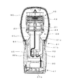
前記した構成のマイクロホン装置によると、マイクロホンユニット10はユニット支持部20と共に、フロントショックマウント部材41およびリアショックマウント部材42を介して、マイクロホンケース30内に取り付けられている。
したがって、マイクロホンケース30にたとえ衝撃が加わっても、図3および図6に示すように、マイクロホンユニット10への衝撃の伝達が効果的に緩和され、振動雑音の発生を抑制することができる。
According to the microphone device having the above-described configuration, the
Therefore, even if a shock is applied to the
加えて、マイクロホンユニット10側からの電気信号を、出力コネクタ47側に供給するマイクケーブル45の一部は、リアショックマウント部材42に沿って取り付けられているので、マイクケーブル45を介したマイクロホンユニット10側への振動の伝送を効果的に阻止することができる。またリアショックマウント部材42は、マイクケーブル45自身の自由振動を押さえることができるので、一層の振動雑音の抑制効果を発揮することができる。
In addition, since a part of the
なお、以上はコンデンサマイクロホンを例にして説明したが、この発明は例えばダイナミックマイクロホンに適用することができる。特にダイナミックマイクロホンにおいては、ボイスコイルの重量が嵩むことによる慣性力の影響を受け易く、その対策としてより柔らかいショックマウント部材を用いることが望まれる。
この発明によると、ショックマウント部材の比較的大きな変形動作に追従して、マイクケーブル45も同様に変形できるので、マイクケーブルにストレスが加わるのを避けることができるなど、前記した発明の効果の欄に記載した作用効果を得ることができる。
Although the above description has been made by taking the condenser microphone as an example, the present invention can be applied to, for example, a dynamic microphone. In particular, in a dynamic microphone, it is susceptible to the influence of inertia force due to the weight of the voice coil, and it is desirable to use a softer shock mounting member as a countermeasure.
According to the present invention, the
10 マイクロホンユニット
11 第1エレメント
12 第2エレメント
13 ユニットケース
20 ユニット支持部
21 ドーム状カバー
22 回路基板
23 中継ロッド
30 マイクロホンケース
41 フロントショックマウント部材
41a 薄肉部
41b 円筒部
41c 円筒部
42 リアショックマウント部材
42a 薄肉部
42b 取り付け部
42c 円筒部
42d 貫通孔
43 円筒体
45 マイクケーブル
47 出力コネクタ
47a 端子ピン
50 フロントメッシュ
DESCRIPTION OF
Claims (6)
前記マイクケーブルの一部が、前記ショックマウント部材に沿って、取り付けられていることを特徴とするマイクロホン装置。 A microphone unit that receives an acoustic wave and outputs an electrical signal, a microphone case supporting the microphone unit internally via a shock mount member formed of an elastic material, and an electrical signal from the microphone unit side are the microphone case A microphone device comprising a microphone cable for supplying an attached output connector, the microphone device comprising:
A microphone device characterized in that a part of the microphone cable is attached along the shock mount member.
Priority Applications (2)
| Application Number | Priority Date | Filing Date | Title |
|---|---|---|---|
| JP2015160636A JP6516626B2 (en) | 2015-08-17 | 2015-08-17 | Microphone device |
| US15/189,552 US9900684B2 (en) | 2015-08-17 | 2016-06-22 | Microphone device |
Applications Claiming Priority (1)
| Application Number | Priority Date | Filing Date | Title |
|---|---|---|---|
| JP2015160636A JP6516626B2 (en) | 2015-08-17 | 2015-08-17 | Microphone device |
Publications (2)
| Publication Number | Publication Date |
|---|---|
| JP2017041674A JP2017041674A (en) | 2017-02-23 |
| JP6516626B2 true JP6516626B2 (en) | 2019-05-22 |
Family
ID=58158153
Family Applications (1)
| Application Number | Title | Priority Date | Filing Date |
|---|---|---|---|
| JP2015160636A Expired - Fee Related JP6516626B2 (en) | 2015-08-17 | 2015-08-17 | Microphone device |
Country Status (2)
| Country | Link |
|---|---|
| US (1) | US9900684B2 (en) |
| JP (1) | JP6516626B2 (en) |
Cited By (2)
| Publication number | Priority date | Publication date | Assignee | Title |
|---|---|---|---|---|
| WO2024111228A1 (en) | 2022-11-25 | 2024-05-30 | 株式会社オーディオテクニカ | Microphone |
| WO2024111227A1 (en) | 2022-11-25 | 2024-05-30 | 株式会社オーディオテクニカ | Microphone |
Families Citing this family (2)
| Publication number | Priority date | Publication date | Assignee | Title |
|---|---|---|---|---|
| CN105245984B (en) * | 2015-10-26 | 2018-01-19 | 苏州登堡电子科技有限公司 | Cylindrical contact formula microphone |
| JP2024137332A (en) * | 2023-03-24 | 2024-10-07 | 株式会社デンソー | Body sound detector |
Family Cites Families (20)
| Publication number | Priority date | Publication date | Assignee | Title |
|---|---|---|---|---|
| NL7216501A (en) * | 1972-12-06 | 1974-06-10 | ||
| US3989905A (en) * | 1975-12-15 | 1976-11-02 | Shure Brothers Inc. | Microphone |
| JPS5639233Y2 (en) * | 1977-03-23 | 1981-09-12 | ||
| AT371658B (en) * | 1981-09-24 | 1983-07-25 | Akg Akustische Kino Geraete | ELASTIC STORAGE FOR ELECTROACOUSTIC TRANSDUCERS |
| SE450330B (en) * | 1982-10-05 | 1987-06-22 | Palmaer Tore | HALLETS FOR ADJUSTABLE MOUNTING OF A MICROPHONE AND / OR HORTELPHONE IN A HELMET, HEARING PROTECTION OR LIKE |
| JPS6045582U (en) * | 1983-09-07 | 1985-03-30 | パイオニア株式会社 | microphone |
| JP3208827B2 (en) * | 1992-02-29 | 2001-09-17 | ソニー株式会社 | Microphone |
| US5363452A (en) * | 1992-05-19 | 1994-11-08 | Shure Brothers, Inc. | Microphone for use in a vibrating environment |
| US5410608A (en) * | 1992-09-29 | 1995-04-25 | Unex Corporation | Microphone |
| JPH0888888A (en) * | 1994-09-20 | 1996-04-02 | Matsushita Electric Ind Co Ltd | Microphone |
| JP3524754B2 (en) * | 1998-02-27 | 2004-05-10 | 株式会社オーディオテクニカ | Microphone |
| JP4000217B2 (en) * | 1998-05-15 | 2007-10-31 | 株式会社オーディオテクニカ | Microphone |
| JP2002281582A (en) * | 2001-03-14 | 2002-09-27 | Matsushita Electric Ind Co Ltd | Microphone |
| AT413924B (en) * | 2001-04-24 | 2006-07-15 | Akg Acoustics Gmbh | MICROPHONE CAPSULE STORAGE |
| JP4895829B2 (en) | 2007-01-16 | 2012-03-14 | 株式会社オーディオテクニカ | Microphone |
| JP5595143B2 (en) * | 2010-06-30 | 2014-09-24 | 株式会社オーディオテクニカ | Dynamic microphone |
| JP5527615B2 (en) * | 2010-12-02 | 2014-06-18 | 株式会社オーディオテクニカ | Dynamic microphone |
| US20120201411A1 (en) * | 2011-02-09 | 2012-08-09 | Kang-Chao Chang | Audio pick-up device of a condenser microphone |
| JP6053161B2 (en) * | 2013-05-31 | 2016-12-27 | 株式会社オーディオテクニカ | Condenser microphone |
| JP6108392B2 (en) | 2013-06-24 | 2017-04-05 | 株式会社オーディオテクニカ | Handheld microphone |
-
2015
- 2015-08-17 JP JP2015160636A patent/JP6516626B2/en not_active Expired - Fee Related
-
2016
- 2016-06-22 US US15/189,552 patent/US9900684B2/en not_active Expired - Fee Related
Cited By (3)
| Publication number | Priority date | Publication date | Assignee | Title |
|---|---|---|---|---|
| WO2024111228A1 (en) | 2022-11-25 | 2024-05-30 | 株式会社オーディオテクニカ | Microphone |
| WO2024111227A1 (en) | 2022-11-25 | 2024-05-30 | 株式会社オーディオテクニカ | Microphone |
| EP4626017A1 (en) | 2022-11-25 | 2025-10-01 | Audio-Technica Corporation | Microphone |
Also Published As
| Publication number | Publication date |
|---|---|
| JP2017041674A (en) | 2017-02-23 |
| US9900684B2 (en) | 2018-02-20 |
| US20170055068A1 (en) | 2017-02-23 |
Similar Documents
| Publication | Publication Date | Title |
|---|---|---|
| US7619498B2 (en) | Vibrator | |
| TWI437894B (en) | Multi function speaker | |
| JP6516626B2 (en) | Microphone device | |
| JP4146346B2 (en) | Multi-function vibration actuator | |
| US9042582B2 (en) | Coaxial passive radiation monomer | |
| JP6767638B2 (en) | Bone conduction speaker and bone conduction headphone device | |
| TWI530200B (en) | Speaker structure | |
| JP6053161B2 (en) | Condenser microphone | |
| JP5808284B2 (en) | Unidirectional condenser microphone | |
| US9578422B2 (en) | Microphone capable of actively counteracting noise attributed to undesired vibration | |
| EP2816820A2 (en) | Moving-magnet transducer | |
| JP6398140B2 (en) | Speaker device and speaker system | |
| CN106028234B (en) | Vibrating diaphragm and loudspeaker monomer | |
| JP6104735B2 (en) | Condenser microphone | |
| KR101281539B1 (en) | Resonator integrated speaker | |
| US9674594B2 (en) | Speaker | |
| CN209982723U (en) | Drives and Mobile Terminals | |
| JP2005203972A (en) | Dome-like diaphragm and speaker device | |
| JP5611133B2 (en) | Microphone adapter | |
| JP3896546B2 (en) | Microphone unit holding structure | |
| CN203340279U (en) | Moving Magnet Transducer | |
| JP5450044B2 (en) | Unidirectional condenser microphone unit and close-talking condenser microphone | |
| JP6872438B2 (en) | Vacuum double structure and speaker device | |
| JP4538341B2 (en) | Dynamic microphone unit | |
| KR101140239B1 (en) | Multi function speaker having the structure preventing deformation |
Legal Events
| Date | Code | Title | Description |
|---|---|---|---|
| A621 | Written request for application examination |
Free format text: JAPANESE INTERMEDIATE CODE: A621 Effective date: 20180523 |
|
| A977 | Report on retrieval |
Free format text: JAPANESE INTERMEDIATE CODE: A971007 Effective date: 20190312 |
|
| TRDD | Decision of grant or rejection written | ||
| A01 | Written decision to grant a patent or to grant a registration (utility model) |
Free format text: JAPANESE INTERMEDIATE CODE: A01 Effective date: 20190325 |
|
| A61 | First payment of annual fees (during grant procedure) |
Free format text: JAPANESE INTERMEDIATE CODE: A61 Effective date: 20190416 |
|
| R150 | Certificate of patent or registration of utility model |
Ref document number: 6516626 Country of ref document: JP Free format text: JAPANESE INTERMEDIATE CODE: R150 |
|
| LAPS | Cancellation because of no payment of annual fees |