JP6516622B2 - Threshing device - Google Patents
Threshing device Download PDFInfo
- Publication number
- JP6516622B2 JP6516622B2 JP2015155401A JP2015155401A JP6516622B2 JP 6516622 B2 JP6516622 B2 JP 6516622B2 JP 2015155401 A JP2015155401 A JP 2015155401A JP 2015155401 A JP2015155401 A JP 2015155401A JP 6516622 B2 JP6516622 B2 JP 6516622B2
- Authority
- JP
- Japan
- Prior art keywords
- threshing
- shaped
- arc
- cylinder
- drum
- Prior art date
- Legal status (The legal status is an assumption and is not a legal conclusion. Google has not performed a legal analysis and makes no representation as to the accuracy of the status listed.)
- Active
Links
Images

Landscapes
- Threshing Machine Elements (AREA)
Description
本発明は、扱胴とその扱胴の下方に配設した受網とを備え、受網に、扱胴の周方向に沿う円弧状の弧状枠部材と、扱胴の軸線方向に沿う直線状の杆状桟部材と、が備えられた脱穀装置に関する。 The present invention comprises a threshing drum and a net disposed below the throttling drum, and the net includes an arc-shaped arc-shaped frame member along the circumferential direction of the throttling drum, and a linear shape along the axial direction of the throttling drum The present invention relates to a threshing device provided with
従来、脱穀装置においては、受網として、扱胴の周方向に沿う円弧状に形成された板金製の第一桟部材と、扱胴の軸心方向に沿う棒状の円形断面を有した第二桟部材とを用いて、格子状の受け網を構成した構造のものが知られている(例えば特許文献1参照)。 Conventionally, in a threshing apparatus, as a receiving net, a first plate member made of a sheet metal formed in an arc shape along the circumferential direction of a threshing cylinder and a second circular member having a rod-like circular cross section along an axial center direction of the threshing cylinder The thing of the structure which comprised the grid | lattice-like receiving net using the crosspiece member is known (for example, refer patent document 1).
上記構造の受網を備えた脱穀装置では、第一桟部材における扱胴側の端縁から、円形断面を有した第二桟部材を扱胴側へ突出させてあるので、第一桟部材の扱胴側端縁のエッジに対する作物の当接が抑制され、作物の損傷を回避し易い点で有用である。
しかしながら、この構造のものでは次の点で改善の余地がある。
つまり、このような受網を構成するに際しては、受網として必要な開口率と強度を備えることが求められるのであるが、この構造のものでは受網として必要な開口率を大きく確保するために、第一桟部材や第二桟部材を平面視で比較的幅狭なものにより構成している。そして受網としての強度を保つために、第一桟部材や第二桟部材の使用個数が多くなる傾向がある。このため、受網全体としての重量や加工工数が大きくなったり、受網の漏下性能が低減する可能性がある。
In the threshing apparatus provided with the above-described mesh, since the second cross member having a circular cross section is made to project to the threshing drum side from the edge on the threshing drum side of the first cross member, The contact of the crop with the edge of the threshing cylinder side edge is suppressed, which is useful in that it is easy to avoid crop damage.
However, this structure has room for improvement in the following points.
That is, when constructing such a net, it is required to have the aperture ratio and strength necessary for the net, but in this structure, in order to secure a large aperture ratio necessary for the net. The first bar member and the second bar member are configured to be relatively narrow in plan view. And in order to maintain the intensity | strength as a receiving net, there exists a tendency for the number of usage of a 1st cross member and a 2nd cross member to increase. For this reason, there is a possibility that the weight and the number of processing steps as a whole of the receiving net may be increased, and the leakage performance of the receiving net may be reduced.
本発明は、受網として必要な開口率と強度を確保するとともに、比較的軽量で被処理物の漏下性能にも優れた構造の脱穀装置を提供しようとするものである。 An object of the present invention is to provide a threshing device having a structure that is relatively lightweight and is also excellent in the leakage performance of the object while securing the aperture ratio and strength necessary for receiving nets.
本発明における脱穀装置の特徴は、扱胴とその扱胴の下方に配設した受網とを備えた脱穀装置であって、前記受網に、前記扱胴の周方向に沿う円弧状に形成され前記扱胴の軸線方向で離れて位置する一対の弧状枠部材と、前記扱胴の軸線方向に沿う直線状に形成され前記扱胴の周方向で所定間隔の隙間を空けて並列された複数個の杆状桟部材と、が備えられ、前記弧状枠部材同士にわたって前記杆状桟部材が架設されることにより前記受網が構成され、前記杆状桟部材が丸パイプ材で構成され、前記弧状枠部材は、前記扱胴の周方向に沿う板面を備えた周方向板部と、前記扱胴の径方向に沿うとともに前記軸線方向に直交する方向に沿う板面を備えた径方向板部と、が組み合わされたL字状断面に形成され、前記杆状桟部材の前記軸線方向の端部が前記径方向板部との間に隙間を有した状態で前記周方向板部に固定されている点に特徴がある。 A feature of the threshing apparatus according to the present invention is a threshing apparatus comprising a threshing drum and a net provided below the threshing drum, wherein the net is formed in an arc shape along the circumferential direction of the threshing drum And a plurality of arc-shaped frame members spaced apart in the axial direction of the threshing cylinder, and a plurality of linear members formed in a straight line along the axial direction of the Individual hook-shaped crosspieces, and the net-shaped crosspieces are constructed by bridging the crosspieces across the arc-shaped frame members, and the net-shaped crosspieces are made of a round pipe member , The arc-shaped frame member includes a circumferential plate portion including a plate surface along a circumferential direction of the threshing cylinder, and a radial direction including a plate surface along a radial direction of the throttling cylinder and a direction orthogonal to the axial direction. And an L-shaped cross section in which the plate portion is combined, and the axial direction of Parts is characterized in that it is fixed to the circumferential plate portion in a state in which a gap between the radial plate portion.
本発明によれば、杆状桟部材が丸パイプ材で構成されているので、同重量の中実の棒状部材で構成した場合より杆状桟部材の外径を大きく形成することが可能となる。
その結果、径の大きい丸パイプを用いることによって、被処理物中の茎稈屑が絡まり難くて滑り落ち易くなるという利点がある。
また、径を大きくしたことで、杆状桟部材自体の曲げ強度が大きくなるので、一対の弧状枠部材同士の間における中桟部材の使用個数を低減することができ、受網全体の重量を軽減し易くなり、受網の開口率も大きく確保し得るという利点がある。
According to the present invention, since the wedge-shaped crosspiece member is formed of a round pipe material, the outer diameter of the wedge-shaped crosspiece member can be formed larger than that of a solid rod-shaped member of the same weight. .
As a result, by using a round pipe with a large diameter, there is an advantage that the stalk scraps in the object to be treated are unlikely to be entangled and slip off easily.
Further, since the bending strength of the cocoon-shaped crosspiece member itself is increased by increasing the diameter, the number of use of the crosspieces between the pair of arc-shaped frame members can be reduced, and the weight of the entire net can be obtained. There is an advantage that it is easy to reduce and the aperture ratio of the receiving net can be secured large.
そして、本構成を備えることで、予め枠組みされた弧状枠部材に対して、杆状桟部材を後付けで取り付ける作業が行い易くなる。
例えば、扱胴の軸線方向で離れて位置する一対の弧状枠部材の一端部同士を、扱胴の軸線方向に沿う別の枠部材で連結し、弧状枠部材の他端部同士を、さらに別の枠部材で連結して、ほぼ矩形状の枠体を組み上げてから、その矩形状の枠体の弧状枠部材同士にわたって杆状桟部材を溶接固定する場合を考える。
この場合に、杆状桟部材の軸線方向の端部が弧状枠部材の径方向板部との間に隙間がない状態で組み上げるには、すべての杆状桟部材の軸線方向長さを、正確に弧状枠部材同士の間隔と合致するように構成しなければならない。しかし、この発明によれば、各杆状桟部材の軸線方向長さに多少のバラツキがあっても、杆状桟部材の軸線方向の端部と径方向板部との間の隙間を有効利用し、その長さの誤差を吸収して支障なく組み上げることができる。
And, by providing the present configuration, the work of attaching the hook-shaped crosspiece member to the arc frame member, which has been framed in advance, can be performed easily.
For example, one end of a pair of arc-shaped frame members located apart in the axial direction of the threshing cylinder is connected by another frame member along the axial direction of the threshing cylinder, and the other ends of the arc-shaped frame members are further separated A case will be considered in which, after assembling the substantially rectangular frame members by connecting them with the frame members, and fixing the hook-like bar members over the arc-shaped frame members of the rectangular frame members.
In this case, in order to assemble the end portions in the axial direction of the bar-shaped cross member with no gap between the radial plate portion of the arc-shaped frame member, the axial lengths of all the bar-shaped cross members are exactly The spacing between the arc frame members must be matched. However, according to the present invention, the gap between the axial end of the wedge member and the radial plate portion is effectively used even if the axial length of each wedge member varies somewhat. Can be assembled without any problem by absorbing the error of its length.
本発明においては、前記杆状桟部材の前記周方向板部に固定された端部では、前記径方向板部に対向する前記杆状桟部材の端縁を含む範囲が、前記周方向板部に溶接固定されていると好適である。 In the present invention, at an end of the gutter-shaped member fixed to the circumferential plate portion, a range including an end edge of the gutter-shaped member facing the radial direction plate portion is the circumferential plate portion It is preferable that they be fixed by welding.
本構成のように、径方向板部に対向する杆状桟部材の端縁を含む範囲が、周方向板部に溶接固定されると、例えば杆状桟部材の端部のうちで、杆状桟部材の長手方向に沿う方向でのみ、周方向板部に溶接固定された構造に比べ、溶接線をより長く確保でき、連結強度を向上し得る。 As in the present configuration, when the range including the end edge of the wedge-shaped crosspiece member facing the radial direction plate part is welded and fixed to the circumferential direction plate part, for example, the edge of the wedge-shaped crosspiece member Only in the direction along the longitudinal direction of the cross member, a longer weld line can be secured and the connection strength can be improved as compared with the structure welded and fixed to the circumferential plate portion.
本発明においては、前記杆状桟部材を構成する前記丸パイプ材の直径は、前記所定間隔の半分以上に設定されていると好適である。 In the present invention, it is preferable that the diameter of the round pipe material constituting the bowl-shaped crosspiece member is set to half or more of the predetermined interval.
本発明によれば、杆状桟部材を構成する丸パイプ材の直径が、被処理物中の作物粒の通過を許容するための所定間隔の半分以上であるように構成されているので、比較的太く形成されることになる。このため、丸パイプの周面を作物粒が滑落し易くなり、また作物粒以外の鞘や茎葉部分などの絡まりが生じ難くなる傾向がある。 According to the present invention, the diameter of the round pipe material constituting the bowl-shaped crosspiece member is configured to be half or more of the predetermined interval for allowing the passage of the crop grain in the object to be treated. It will be formed thick. For this reason, there is a tendency for the crop grains to slide down on the peripheral surface of the round pipe, and to make it difficult to cause tangles such as sheaths and foliage parts other than the crop grains.
本発明においては、前記杆状桟部材を構成する前記丸パイプ材の直径は、前記所定間隔よりも小さく設定されていると好適である。 In the present invention, it is preferable that the diameter of the round pipe material forming the bowl-shaped crosspiece member is set smaller than the predetermined interval.
本発明によれば、杆状桟部材を構成する丸パイプ材の直径が、作物粒の通過を許容するための所定間隔よりは小さく構成されているので、丸パイプの存在によって受網全体の開口率が低減されたり、受網重量が増大する虞を回避できる。 According to the present invention, since the diameter of the round pipe material constituting the bowl-shaped crosspiece member is smaller than the predetermined interval for allowing the passage of crop grains, the opening of the entire net by the presence of the round pipe It is possible to avoid the possibility of reducing the rate or increasing the weight of the net.
本発明においては、前記受網は、前記扱胴の回転軸心を境にした一方側に相当する領域に存在する第一受網体と、前記回転軸心を境にした他方側に相当する領域に存在する第二受網体と、に分割形成され、複数個の前記杆状桟部材は、前記第一受網体と第二受網体との突き合わせ端部に最も近い位置の前記杆状桟部材を起点にして、前記所定間隔の隙間を空けて配設されていると好適である。 In the present invention, the above-mentioned net corresponds to a first receiving net which exists in a region corresponding to one side bordering the rotation axis of the threshing drum and the other side bordering the rotation axis. The second reeds present in the region are divided and formed, and a plurality of the shed-like members are located closest to the butt end of the first and second reeds. It is preferable that the above-mentioned predetermined intervals be provided starting from the crosspiece member.
本発明によれば、最も被処理物の多くが存在し易い箇所であるところの、扱胴の回転軸心の下方近くにおける受網の開口率を適正な範囲に保って、受網からの作物粒の漏下率を適正な状態に維持し易く、良好な脱穀性能を確保し易い。 According to the present invention, a crop from the net is maintained in an appropriate range, with the opening ratio of the net near the lower side of the rotary shaft center of the threshing cylinder, which is the place where most of the objects to be treated are most easily It is easy to maintain the leak rate of the grain in an appropriate state, and easy to secure good threshing performance.
本発明においては、前記弧状枠部材は、前記扱胴の周方向に沿う板面を備えた周方向板部と、前記扱胴の径方向に沿うとともに前記軸線方向に直交する方向に沿う板面を備えた径方向板部と、が組み合わされたL字状断面に形成され、前記杆状桟部材の外周面のうち前記扱胴の回転軸心から遠い側の外周面までの距離が、前記径方向板部における前記扱胴の回転軸心から遠い側の端縁までの距離と同程度に設定されていると好適である。 In the present invention, the arc-shaped frame member is a circumferential plate portion provided with a plate surface along the circumferential direction of the threshing cylinder, and a plate surface along the radial direction of the threshing cylinder and a direction orthogonal to the axial direction And an L-shaped cross-section in which the radial direction plate portion provided with the L-shaped cross section is combined, and the distance from the outer peripheral surface of the wedge member to the outer peripheral surface far from the rotational axis of the threshing cylinder is It is preferable that the radial direction plate portion be set to the same degree as the distance from the rotation axis of the threshing cylinder to the end edge on the far side.
本発明によれば、隣り合う杆状桟部材の周面同士の間隔を作物粒が通過して落下する際に、作物粒が弧状枠部材の径方向板部に引っかかる虞が少ない。
つまり、作物粒は杆状桟部材の外周面に沿って後方へ送られながら落下移動する。このため、弧状枠部材の径方向板部における扱胴の回転軸心から遠い側の端縁が、杆状桟部材の外周面のうち扱胴の回転軸心から遠い側の外周面よりも大きく下方側へ突出していると、落下しながら後方移動する作物粒が弧状枠部材の径方向板部に引っかかって傷ついたり汚れが生じる虞がある。これに比べて、この発明では、杆状桟部材の外周面のうち扱胴の回転軸心から遠い側の外周面までの距離が、径方向板部における扱胴の回転軸心から遠い側の端縁までの距離と同程度に設定されているので、このような不具合の発生を回避し易い。
According to the present invention, when the crop grain passes through the gap between the circumferential surfaces of the adjacent gutter-shaped crosspieces and falls, the crop grain is less likely to be caught by the radial direction plate portion of the arc-shaped frame member.
That is, the crop grains drop and move while being fed backward along the outer peripheral surface of the bowl-shaped crosspiece. For this reason, the end edge of the radial plate portion of the arc-shaped frame member on the side far from the rotational axis of the threshing drum is larger than the outer peripheral surface of the side of the rim member on the side far from the rotational axis of the threshing cylinder. If it projects downward, crop grains moving backward while falling may be caught on the radial plate portion of the arc-shaped frame member, resulting in damage or contamination. In the present invention, on the other hand, in the present invention, the distance to the outer peripheral surface on the side far from the rotational axis of the threshing drum among the outer peripheral surfaces of the gutter-shaped crosspiece member Since the distance to the edge is set to the same degree, the occurrence of such a defect can be easily avoided.
本発明においては、扱胴とその扱胴の下方に配設した受網とを備えた脱穀装置であって、前記受網に、前記扱胴の周方向に沿う円弧状に形成され前記扱胴の軸線方向で離れて位置する一対の弧状枠部材と、前記扱胴の軸線方向に沿う直線状に形成され前記扱胴の周方向で所定間隔の隙間を空けて並列された複数個の杆状桟部材と、が備えられ、前記弧状枠部材同士にわたって前記杆状桟部材が架設されることにより前記受網が構成され、前記杆状桟部材が丸パイプ材で構成され、前記受網において、一対の前記弧状枠部材同士の間に、前記扱胴の周方向に沿う円弧状に形成されるとともに、前記軸線方向に直交する方向に沿う板面を有した中桟部材を備え、この中桟部材の前記扱胴に近い側の端縁に、その端縁よりも前記扱胴側に突出した状態で前記杆状桟部材が連結され、
前記中桟部材における前記扱胴の径方向での前記扱胴から遠い側の端縁と、前記丸パイプ材の外周面との間における最短距離が、前記丸パイプ材の半径よりも小さく設定されていると好適である。
In the present invention, there is provided a threshing apparatus comprising a threshing drum and a net provided below the throttling barrel, wherein the net is formed in an arc shape along the circumferential direction of the threshing drum and the threshing drum A pair of arc-shaped frame members spaced apart in the axial direction of the sleeve, and a plurality of bowl-like members formed in a straight line along the axial direction of the threshing cylinder and spaced apart in the circumferential direction of the A crosspiece member is provided, and the gauze-shaped crosspiece member is provided across the arc-shaped frame members to constitute the above-mentioned mesh, and the gauze-shaped crosspiece member is formed of a round pipe material ; Between the pair of arc-shaped frame members, an intermediate cross member formed in an arc shape along the circumferential direction of the threshing drum and having a plate surface along a direction orthogonal to the axial direction, The end edge of the member closer to the threshing cylinder, which protrudes toward the threshing cylinder side than the end edge The rod-shaped beam member is coupled in,
The shortest distance between the end of the middle cross member in the radial direction of the threshing cylinder and the outer peripheral surface of the round pipe material in the radial direction of the threshing cylinder is set smaller than the radius of the round pipe material it is preferable to have that.
本発明によれば、杆状桟部材が丸パイプ材で構成されているので、同重量の中実の棒状部材で構成した場合より杆状桟部材の外径を大きく形成することが可能となる。
その結果、径の大きい丸パイプを用いることによって、被処理物中の茎稈屑が絡まり難くて滑り落ち易くなるという利点がある。
また、径を大きくしたことで、杆状桟部材自体の曲げ強度が大きくなるので、一対の弧状枠部材同士の間における中桟部材の使用個数を低減することができ、受網全体の重量を軽減し易くなり、受網の開口率も大きく確保し得るという利点がある。
さらにまた、中桟部材を備えたことにより、被処理物中の作物粒が中桟部材に接触する可能性を低減でき、中桟部材に引っかかって作物粒が傷ついたり汚れを生じる虞が少ない。
そして、丸パイプ材の外周面よりも扱胴から離れる側に位置する中桟部材は、丸パイプ材の外周面よりも扱胴から離れる側への突出量を、丸パイプ材の半径よりも小さい範囲に制限されているので、その突出部分に作物粒が引っかかる可能性を低減できる。
According to the present invention, since the wedge-shaped crosspiece member is formed of a round pipe material, the outer diameter of the wedge-shaped crosspiece member can be formed larger than that of a solid rod-shaped member of the same weight. .
As a result, by using a round pipe with a large diameter, there is an advantage that the stalk scraps in the object to be treated are unlikely to be entangled and slip off easily.
Further, since the bending strength of the cocoon-shaped crosspiece member itself is increased by increasing the diameter, the number of use of the crosspieces between the pair of arc-shaped frame members can be reduced, and the weight of the entire net can be obtained. There is an advantage that it is easy to reduce and the aperture ratio of the receiving net can be secured large.
Furthermore, the provision of the center cross member can reduce the possibility that crop grains in the object to be processed come into contact with the middle cross bar member, and there is little risk of the crop cross being damaged or soiled.
And the middle cross member located on the side away from the threshing cylinder than the outer peripheral surface of the round pipe material has a smaller amount of protrusion to the side away from the threshing cylinder than the outer peripheral surface of the round pipe material than the radius of the circular pipe material Being limited to the range, the possibility of the crop grains being caught on the projecting portion can be reduced.
本発明においては、前記中桟部材における前記扱胴の径方向での前記扱胴から遠い側の端縁は、前記丸パイプ材の外周面よりも前記扱胴から離れる側に位置していると好適である。 In the present invention, the end of the intermediate cross member in the radial direction of the threshing cylinder which is farther from the threshing cylinder is located on the side farther from the threshing cylinder than the outer peripheral surface of the round pipe material. It is suitable.
本発明によれば、丸パイプ材の外周面よりも扱胴から離れる側にも中桟部材が位置しているので、被処理物中の作物粒との接触を回避し易い構造の中桟部材を採用しながらも、受網全体の強度を向上し得る。 According to the present invention, since the middle cross bar member is also located on the side farther from the threshing drum than the outer peripheral surface of the round pipe material, the middle cross bar member having a structure that easily avoids contact with crop grains in the object to be treated. In addition, the overall strength of the receiving network can be improved.
以下、本発明の実施の形態の一例を図面の記載に基づいて説明する。
尚、本実施形態での説明における前後方向及び左右方向は、特段の説明がない限り、次のように記載している。つまり、本発明を適用した普通型コンバインなどの走行機体1の作業走行時における前進側の進行方向(図1における矢印F参照)が「前」、後進側への進行方向(図1における矢印B参照)が「後」、その前後方向での前向き姿勢を基準としての右側に相当する方向(図3における矢印R参照)が「右」、同様に左側に相当する方向(図3における矢印L参照)が「左」である。
Hereinafter, an example of an embodiment of the present invention will be described based on the description of the drawings.
In the description of the present embodiment, the front-rear direction and the left-right direction are described as follows, unless otherwise specified. That is, the traveling direction (refer to arrow F in FIG. 1) on the forward side during work traveling of traveling body 1 such as a regular combine to which the present invention is applied is "forward" and the traveling direction to backward (arrow B in FIG. (See arrow), the direction (see arrow R in Fig. 3) corresponding to the right with respect to the forward posture in the front and rear direction (see arrow R in Fig. 3) corresponds to the right (see arrow L in FIG. 3). ) Is "left".
〔全体構成〕
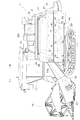
図1は、豆類を収穫する普通形コンバインの全体側面図である。このコンバインは、機体フレーム10が左右一対のクローラ走行装置11に搭載されている。機体フレーム10には、作物を脱穀処理する脱穀装置2、及び作物を貯留及び排出する作物回収装置12が左右に並列して配備されており、作物回収装置12の前方に運転キャビン13が搭載され、脱穀装置2の前方に位置する状態で刈取搬送装置14が設けられている。
また、運転キャビン13の下部に位置する状態で、前記クローラ走行装置11、刈取搬送装置14、脱穀装置2、及び作物回収装置12を駆動するための動力を供給するエンジン15が搭載されている。
〔overall structure〕
FIG. 1 is an overall side view of a common type combine harvesting beans. The
In addition, the engine 15 for supplying power for driving the
脱穀装置2の前方に配設される刈取搬送装置14は、後端側の横向き支点x1周りで上下揺動自在に刈取作物搬送用のフィーダ16が連結されている。フィーダ16の前端側には、バリカン型の刈刃(図示せず)を備えて、略機体横幅に相当する刈幅を有して植立作物を刈り取り、フィーダ16に送り込む刈取部17が連結されている。
The
フィーダ16には、掻き揚げコンベア16Aが内装されており、刈取部17から供給された被処理物をフィーダ16の底面に沿って搬送して、脱穀装置2に供給できるように構成されている。
普通型コンバインで収穫される処理対象作物としては、稲麦、稗、粟、豆類、ごま、菜種など種々のものが存在するが、ここでは、大豆を収穫する処理対象作物としている。以下において、処理対象作物である大豆全体をコンバインによる何らの処理を受ける過程で被処理物と称し、被処理物のうち、収穫の目的とする大豆粒を作物粒と称し、鞘や茎葉を排出物と称する。
A scraping
Various crops such as rice, wheat, straw, beans, beans, sesame and rapeseed exist as crops to be harvested by ordinary combine, but here, crops to be harvested are soybeans. In the following, the whole soybean to be treated is referred to as an object to be treated in the process of receiving any treatment with the combine, and among the objects to be treated, soybean grains to be harvested are referred to as crop grains, and pods and stems and leaves are discharged. It is called a thing.
脱穀装置2に投入された被処理物は、脱穀装置2内で、脱穀及び選別処理される。被処理物のうち、選別された後の作物粒が作物回収装置12に送られ、作物回収装置12のアンローダ12Aから外部へ取り出される。選別された後の排出物は、脱穀装置2の後端部に備えた細断装置18を経て細断された後、機外へ落下放出される。
The material input to the threshing
〔脱穀装置〕
脱穀装置2は次のように構成されている。
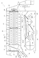
図2及び図3に示されるように、脱穀装置2は、脱穀ケース20の内部で、その上部箇所に被処理物を脱穀処理するための脱穀部2Aが備えられ、脱穀ケース20内部の下部箇所に、脱穀処理後の被処理物を選別処理するための選別部2Bが備えられている。脱穀部2Aには、回転軸心z1を走行機体1の前後方向に沿わせた軸流形の扱胴3が備えられ、選別部2Bには扱胴3の下方に位置し、被処理物を前方から後方へ向けて揺動移送する揺動選別装置5が備えられている。
この脱穀装置2においては、脱穀部2Aにおける脱穀処理方向及び選別部2Bにおける選別処理方向が、共に走行機体1の前後方向に沿い、かつ被処理物の移送方向は、上手側が走行機体1の前方側で、下手側が走行機体1の後方側であるように設定されている。
脱穀ケース20は、扱胴3を支持する前支持板21と、後支持板22と、左右両側に位置する横側板23と、天井部を構成する上部カバー24と、底板25とを備えて矩形箱状に形成されている。
Threshing device
The threshing
As shown in FIG. 2 and FIG. 3, the threshing
In this threshing
The threshing
脱穀ケース20内における脱穀部2Aには、多数のバー部材30aを立設した扱き歯支持体30を、周方向に所定間隔を空けて複数箇所に備えることにより、バータイプに構成された扱胴3が備えられている。この扱胴3は、前後向きの回転軸心z1まわりで回転自在に、かつ正面視で右回り方向fR(図3参照)に回転するように支持されている。扱胴3の前端部には、螺旋羽根31aを備えた掻込送り部31を連設してある。
In the threshing
扱胴3の下方側には、前後方向視で下向きに凸曲した円弧状の受網4が設けられている。この受網4によって脱穀ケース20内の空間が上下に区画されている。つまり、受網4よりも上方側における空間が、扱胴3を内装した扱室を形成するものであり、この空間に配備された扱胴3及び受網4などが脱穀部2Aを構成している。
また、受網よりも下側における空間が、揺動選別装置5などを内装する選別室を形成するものであり、この空間に配備された揺動選別装置5や風選装置6などが選別部2Bを構成している。
On the lower side of the threshing drum 3, an arc-shaped
In addition, the space below the receiving net forms a sorting room in which the
脱穀部2Aでは、フィーダ16によって供給口26から送り込まれた刈取り作物の株元から穂先までの全体を、被処理物として扱胴3と受網4との間に送り込んで脱穀処理し、脱穀処理によって得られた作物粒を受網4から選別部2Bに漏下させ、脱穀処理によって発生した茎葉や鞘などの排出物を排塵口27から細断装置18へ排出する。
In the threshing
選別部2Bには、受網4の下方に位置させて揺動選別装置5が設けられている。
揺動選別装置5は、後端部に備えた偏心カム式の駆動機構5Aが作動することで前後方向に揺動する。揺動選別装置5の前部側における下方位置に風選装置6の送風手段としての唐箕60を配備してある。唐箕60は、図2に示すように、左側面視で左回転する回転羽根によって選別風を発生させる。揺動選別装置5は、揺動しながら受網4から漏下した処理物などを受け止め、受け止めた処理物を選別対象の処理物として選別処理方向下手側に移送しながら篩い選別し、かつ唐箕60からの選別風によって風力選別するように構成されている。
In the
The
揺動選別装置5での選別処理方向における上手側相当箇所の下方に1番回収部51が備えられ、それよりも選別処理方向での下手側相当箇所の下方に2番回収部52が備えられている。1番回収部51の底部、及び2番回収部52の底部には、夫々作物粒搬送用のスクリューを内装してある。1番回収部51の底部に流下した1番物は揚送装置53を介して、作物回収装置12に搬送される。2番回収部52の底部に流下した2番物は、2番還元装置(図示せず)を介して、2番物を揚送し揺動選別装置5に還元する。
The
〔受網〕
脱穀部2Aで用いられる受網4について説明する。
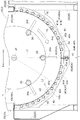
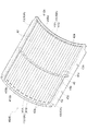
図2乃至図4に示すように、受網4は、扱胴3の回転軸心z1に沿う方向視で、扱胴3の下方側におけるほぼ半周にわたる範囲を覆うように、下向きに凸曲した円弧状に形成されている。そして、扱胴3の回転軸心z1に直交する方向視では、扱胴3の軸線方向に沿った直線状に形成されている。
[Receiver]
The receiving net 4 used in the threshing
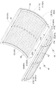
As shown in FIGS. 2 to 4, the
この受網4は、図3及び図4に示すように、左右方向で扱胴3の回転軸心z1を境にした一方側に相当する領域に存在する第一受網体40a(単位受網体40に相当する)と、前記回転軸心z1を境にした他方側に相当する領域に存在する第二受網体40b(単位受網体40に相当する)とに分割形成され、第一受網体40aと第二受網体40bとを組み合わせて扱胴3の下方側を覆うように構成されている。
また受網4は、図2に示すように、扱胴3の軸線方向での前半側の下方に位置する前側受網部4Fと、扱胴3の軸線方向での後半側の下方に位置する後側受網部4Rとの組み合わせで構成されている。前側受網部4Fと後側受網部4Rとの夫々は、前述したように第一受網体40aと第二受網体40bとに分割形成されている。したがって、脱穀部2Aで用いられる受網4は、前側受網部4Fにおける第一受網体40aと第二受網体40b、及び後側受網部4Rにおける第一受網体40aと第二受網体40b、の合計4枚の単位受網体40の組み合わせで構成されている。
As shown in FIG. 3 and FIG. 4, the receiving
Further, as shown in FIG. 2, the
受網4を構成する単位受網体40の夫々は、次のように構成されている。
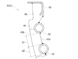
すなわち、受網4に相当する単位受網体40は、その基本構造として、扱胴3の軸線方向で離れて位置する一対の弧状枠部材41と、弧状枠部材41,41同士にわたって架設された杆状桟部材42とを備えている。
一対の弧状枠部材41,41は、それぞれが扱胴3の周方向に沿う円弧状に形成されている。そして、弧状枠部材41,41のうち、一方の弧状枠部材41において円弧状に屈曲形成された周方向での各端部は、他方の弧状枠部材41における周方向での各端部に、直線状外枠部材43を介して連結されている。
この直線状外枠部材43は、扱胴3の軸線方向に沿う直線状に形成された金属板で構成され、各弧状枠部材41における周方向での端部に溶接接続されて、一対の弧状枠部材41とともに矩形状の単位受網体40の外周枠40Aを形成している。
Each of the unit receiving nets 40 constituting the receiving
That is, as a basic structure, the unit receiving
Each of the pair of arc-shaped
The linear
上記のように弧状枠部材41と直線状外枠部材43とで矩形状に形成された外周枠40Aの内側には、扱胴3の軸線方向で離れて位置する一対の弧状枠部材41,41同士にわたって架設された杆状桟部材42が、弧状枠部材41の周方向に沿って、所定間隔d1の隙間を空けて配設されている。各杆状桟部材42は、金属製の丸パイプ材で構成されている。杆状桟部材42同士は、第一受網体40aと第二受網体40bとの突き合わせ端部に最も近い位置の杆状桟部材42を起点にして、前記所定間隔d1の隙間が存在する状態で配設されている。
第一受網体40aと第二受網体40bとは、図3に示すように、扱胴3の回転軸心z1を通る鉛直線y1を境にした一方側に相当する領域に第一受網体40aが存在し、他方側に相当する領域に第二受網体40bが存在し、その突き合わせ端部が前記鉛直線y1の直下に位置する状態で配設されている。そして、第一受網体40aと第二受網体40bとの突き合わせ端部に存在する夫々の直線状外枠部材43に連結穴43aが形成され、この連結穴43aに連結ボルト44を挿通して互いに連結されている(図3及び図4参照)。
As described above, inside the outer
As shown in FIG. 3, the first receiving net 40 a and the second receiving
杆状桟部材42同士の所定間隔d1は、その所定間隔d1を脱穀後の作物粒が停滞なく通過でき、かつ作物粒よりも大きな排出物の漏下を極力抑制し得る大きさの隙間を形成するように設定される。この所定間隔d1との関係で、図3及び図7に示すように、前記杆状桟部材42を構成する丸パイプ材の直径d2が、前記所定間隔d1の半分以上の大きさであるように、かつ、前記所定間隔d1よりも小さく設定されている。また、杆状桟部材42は、所定間隔d1が脱穀後の作物粒の通過を停滞なく行われるに適正であることに加え、杆状桟部材42自身が丸パイプ材で構成されている点でも、丸パイプ材に接触する作物粒の流れをスムースにして、作物粒の汚れを回避し易く構成されている。
The predetermined interval d1 between the gauze-
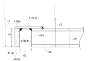
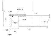
弧状枠部材41は、扱胴3の周方向に沿う円弧状の板面を備えた周方向板部41Aと、扱胴3の径方向に沿うとともに扱胴3の軸線方向に直交する方向に沿う平板状の板面を備えた径方向板部41Bと、が組み合わされてL字状断面を有した形状に構成されている。
平板状の径方向板部41Bは、扱胴3の軸線方向に直交する方向に沿う板面を備えているが、その板面の内周側の端縁41Ba、及び外周側の端縁41Bbは、扱胴3の周方向に沿う円弧状に形成されている。
そして、図8及び図9に示すように、径方向板部41Bの内周側の端縁41Baが周方向板部41Aの外周面に溶接固定され、その周方向板部41Aの外周面に杆状桟部材42も溶接固定されている。
The arc-shaped
The flat
And as shown in FIG.8 and FIG.9, edge 41Ba of the inner peripheral side of radial
このとき、径方向板部41Bの板面のうち、杆状桟部材42の端部に対向する側の板面と、その板面に対向する杆状桟部材42の軸線方向の端縁42aとの間には、ある程度の隙間d3が存在する状態で、杆状桟部材42が周方向板部41Aの外周面に溶接固定される。
このように、径方向板部41Bの板面と杆状桟部材42の軸線方向の端縁42aとの間に隙間d3が存在することで、周方向板部41Aの外周面に杆状桟部材42を溶接固定する際に、周方向板部41Aの外周面に対する杆状桟部材42の溶接長さをできるだけ長く確保し易い。つまり、周方向板部41Aの外周面に対する杆状桟部材42の溶接箇所を、杆状桟部材42の長手方向に沿う方向のみならず、杆状桟部材42の軸線方向の端縁42aと径方向板部41Bとの間の隙間d3を有効利用して、杆状桟部材42の軸線方向の端縁42aに沿う方向でも溶接固定することが可能となる。
そして、このように杆状桟部材42の軸線方向の端縁42aと径方向板部41Bとの間に隙間d3が存在する状態であることにより、各杆状桟部材42の軸線方向長さに多少の加工精度上のバラツキがあっても、前記隙間d3を有効利用して、その長さの誤差を吸収し支障なく組み上げることができる。
At this time, among the plate surfaces of the radial
Thus, the gap d3 is formed on the outer peripheral surface of the
In this manner, the gap d3 is present between the
扱胴3の径方向に沿う方向での前記周方向板部41Aの径方向幅d4は、杆状桟部材42の直径d2と同程度に形成されている。したがって、周方向板部41Aの外周面に溶接固定された状態で、扱胴3の回転軸心z1から周方向板部41Aの外周側の端縁までの距離L1は、扱胴3の回転軸心z1から杆状桟部材42の外周面のうちの、扱胴3の回転軸心z1から遠い側の外周面までの距離L2と同程度になる。
The radial width d4 of the
受網4の一対の弧状枠部材41,41同士の間には、扱胴3の周方向に沿う円弧状に形成されるとともに、扱胴3の軸線方向に直交する方向に沿う板面を有した中桟部材45が配設されている。
この中桟部材45には、図3乃至図7に示すように、その中桟部材45の内外の端縁45a,45bのうち、扱胴3に近い側に位置する内周側の端縁45aよりも扱胴3側に突出した状態で杆状桟部材42が連結されている。
また、中桟部材45の端縁45a,45bのうち、扱胴3の径方向で扱胴3から遠い側に位置する外周側の端縁45bは、杆状桟部材42を構成する丸パイプ材の外周面よりも、扱胴3から離れる側に所定の突出量d5だけ突出する状態で設けられている。この突出量d5は、中桟部材45の外周側の端縁45bと丸パイプ材の外周面との間における最短距離に相当するものであり、杆状桟部材42を構成する丸パイプ材の半径と同等、もしくはそれよりも小さい程度に設定されている。
Between a pair of arc-shaped
As shown in FIGS. 3 to 7, the
Further, of the end edges 45 a and 45 b of the
〔別実施形態の1〕
上記の実施形態では、受網4として、前側受網部4Fと後側受網部4Rとの夫々で、第一受網体40aと第二受網体40bとに分割形成されている単位受網体40を用いて、合計4枚の単位受網体40の組み合わせで構成された構造のものを例示したが、この構造に限定されるものではない。
例えば、さらに細かい範囲で分割された構造の単位受網体40を用いて構成したり、第一受網体40aと第二受網体40bとに分割されていない一体物で構成された構造を採用したり、あるいは全体を一枚の単位受網体40で構成した構造を採用してもよい。
その他の構成は、前述した実施形態と同様の構成を採用すればよい。
[1 of another embodiment]
In the above embodiment,
For example, it is configured using a
The other configuration may adopt the same configuration as that of the embodiment described above.
〔別実施形態の2〕
上記の実施形態では、受網4の単位受網体40として、一対の弧状枠部材41とその各端部を連結する直線状外枠部材43とで矩形状に形成された外周枠40Aを用いて、外周枠40Aの内側に多数の杆状桟部材42が配設された構造のものを例示したが、これに限られるものではない。
例えば、図示はしないが、外周枠40Aの一部を構成する直線状外枠部材43を用いずに、一対の弧状枠部材41,41同士にわたって多数の杆状桟部材42を架設し固定することで単位受網体40を構成してもよい。
この場合、第一受網体40aと第二受網体40bとの接続は、夫々の弧状枠部材41同士を接続することによって行えるようにすると良い。
その他の構成は、前述した実施形態と同様の構成を採用すればよい。
[2 of another embodiment]
In the above embodiment, an outer
For example, although not shown in the drawings, bridging and fixing a large number of hook-shaped
In this case, the connection between the
The other configuration may adopt the same configuration as that of the embodiment described above.
〔別実施形態の3〕
上記の実施形態では、扱胴3の回転軸心z1から周方向板部41Aの外周側の端縁までの距離L1と、扱胴3の回転軸心z1から杆状桟部材42の外周面のうちの、扱胴3の回転軸心z1から遠い側の外周面までの距離L2とが同程度である例を示したが、この構造に限定されるものではない。
例えば、周方向板部41Aの外周側の端縁までの距離L1が、杆状桟部材42の外周面のうちの、扱胴3の回転軸心z1から遠い側の外周面までの距離L2よりも大きい、あるいは逆に小さい構造のものを採用してもよい。
ただし、周方向板部41Aの外周側の端縁までの距離L1が、杆状桟部材42の外周面までの距離L2よりもあまりに大きいと、受網4を通過後の排出物が周方向板部41Aに引っかかる可能性があり、逆に小さすぎると、周方向板部41Aの強度が低下したり、排出物が杆状桟部材42の端縁42aに接触して引っかかる虞があって好ましくない。したがって、大きな差がない程度であるのが好ましい。
その他の構成は、前述した実施形態と同様の構成を採用すればよい。
[3 of another embodiment]
In the above embodiment, the distance L1 from the rotation axis z1 of the threshing drum 3 to the end edge on the outer peripheral side of the
For example, the distance L1 to the edge on the outer peripheral side of the
However, if the distance L1 to the edge on the outer circumferential side of the
The other configuration may adopt the same configuration as that of the embodiment described above.
〔別実施形態の4〕
上記の実施形態では、杆状桟部材42として丸パイプを用いた構造のものを例示したが、丸パイプとしては、断面形状が必ずしも真円形のものに限定されるものではない。例えば、楕円などの長円形状、あるいは上向きに突曲する半円形状の周面を有したもので構成してもよい。
この場合、パイプの長径方向が、扱胴3の半径方向に沿う方向であるのが望ましく、半円形状である場合には、上向きに突曲する円弧状周面の頂部が扱胴3の半径方向に沿う方向であるのが望ましい。
その他の構成は、前述した実施形態と同様の構成を採用すればよい。
[4 of another embodiment]
Although the above-mentioned embodiment illustrated the thing of the structure which used the round pipe as the collar-
In this case, it is preferable that the longitudinal direction of the pipe is the direction along the radial direction of the threshing cylinder 3. If it is semicircular, the top of the arc-shaped circumferential surface protruding upward is the radius of the throttling cylinder 3 It is desirable that the direction is along the direction.
The other configuration may adopt the same configuration as that of the embodiment described above.
本発明は、大豆を処理対象とするものに限らず、稲麦、稗、粟、豆類、ごま、菜種などを収穫対象とするコンバインに適用してもよい。 The present invention may be applied not only to soybeans to be treated, but also to combine harvesters to be used as rice barley, koji, koji, beans, sesame, rapeseed and the like.
3 扱胴
4 受網
40a 第一受網体
40b 第二受網体
41 弧状枠部材
41A 周方向板部
41B 径方向板部
42 杆状桟部材
45 中桟部材
45a 端縁
45b 端縁
d1 所定間隔
d2 直径
d3 隙間
d5 最短距離
L1 距離
L2 距離
z1 回転軸心
DESCRIPTION OF SYMBOLS 3 threshing
Claims (8)
前記受網に、前記扱胴の周方向に沿う円弧状に形成され前記扱胴の軸線方向で離れて位置する一対の弧状枠部材と、前記扱胴の軸線方向に沿う直線状に形成され前記扱胴の周方向で所定間隔の隙間を空けて並列された複数個の杆状桟部材と、が備えられ、
前記弧状枠部材同士にわたって前記杆状桟部材が架設されることにより前記受網が構成され、
前記杆状桟部材が丸パイプ材で構成され、
前記弧状枠部材は、前記扱胴の周方向に沿う板面を備えた周方向板部と、前記扱胴の径方向に沿うとともに前記軸線方向に直交する方向に沿う板面を備えた径方向板部と、が組み合わされたL字状断面に形成され、
前記杆状桟部材の前記軸線方向の端部が前記径方向板部との間に隙間を有した状態で前記周方向板部に固定されている脱穀装置。 A threshing apparatus comprising a threshing drum and a net provided below the threshing drum,
The mesh has a pair of arc-shaped frame members formed in an arc shape along the circumferential direction of the threshing drum and spaced apart in the axial direction of the threshing drum, and formed linearly in the axial direction of the threshing drum A plurality of wedge-shaped crosspiece members arranged in parallel with a predetermined gap therebetween in the circumferential direction of the threshing cylinder;
The mesh is constructed by bridging the bar-like members across the arc-shaped frame members,
The wedge-shaped crosspiece member is made of a round pipe material ,
The arc-shaped frame member includes a circumferential plate portion including a plate surface along a circumferential direction of the threshing cylinder, and a radial direction including a plate surface along a radial direction of the throttling cylinder and a direction orthogonal to the axial direction. The plate portion is formed into an L-shaped cross section combined with each other,
The threshing apparatus is fixed to the said circumferential direction board part in the state which had the clearance gap between the said axial direction edge part of the said gutter-shaped crosspiece member with the said radial direction board part .
複数個の前記杆状桟部材は、前記第一受網体と第二受網体との突き合わせ端部に最も近い位置の前記杆状桟部材を起点にして、前記所定間隔の隙間を空けて配設されている請求項1〜4のいずれか一項記載の脱穀装置。 The first mesh is located in a region corresponding to one side bordering the rotation axis of the threshing drum, and the other is located in a region corresponding to the other side bordering the rotation axis. Divided into two receiving nets,
A plurality of the gauze-like members are spaced apart from the gauze-like members at a position closest to the butt end of the first and second receiving nets at predetermined intervals. The threshing apparatus of any one of Claims 1-4 arrange | positioned.
前記杆状桟部材の外周面のうち前記扱胴の回転軸心から遠い側の外周面までの距離が、前記径方向板部における前記扱胴の回転軸心から遠い側の端縁までの距離と同程度に設定されている請求項1〜5のいずれか一項記載の脱穀装置。 The arc-shaped frame member includes a circumferential plate portion including a plate surface along a circumferential direction of the threshing cylinder, and a radial direction including a plate surface along a radial direction of the throttling cylinder and a direction orthogonal to the axial direction. The plate portion is formed into an L-shaped cross section combined with each other,
The distance from the outer peripheral surface of the rim member to the outer peripheral surface far from the rotational axis of the threshing cylinder is the distance from the radial plate portion to the end edge remote from the rotational axis of the threshing cylinder The threshing apparatus according to any one of claims 1 to 5 , which is set to the same degree.
前記受網に、前記扱胴の周方向に沿う円弧状に形成され前記扱胴の軸線方向で離れて位置する一対の弧状枠部材と、前記扱胴の軸線方向に沿う直線状に形成され前記扱胴の周方向で所定間隔の隙間を空けて並列された複数個の杆状桟部材と、が備えられ、
前記弧状枠部材同士にわたって前記杆状桟部材が架設されることにより前記受網が構成され、
前記杆状桟部材が丸パイプ材で構成され、
前記受網において、一対の前記弧状枠部材同士の間に、前記扱胴の周方向に沿う円弧状に形成されるとともに、前記軸線方向に直交する方向に沿う板面を有した中桟部材を備え、
この中桟部材の前記扱胴に近い側の端縁に、その端縁よりも前記扱胴側に突出した状態で前記杆状桟部材が連結され、
前記中桟部材における前記扱胴の径方向での前記扱胴から遠い側の端縁と、前記丸パイプ材の外周面との間における最短距離が、前記丸パイプ材の半径よりも小さく設定されている脱穀装置。 A threshing apparatus comprising a threshing drum and a net provided below the threshing drum,
The mesh has a pair of arc-shaped frame members formed in an arc shape along the circumferential direction of the threshing drum and spaced apart in the axial direction of the threshing drum, and formed linearly in the axial direction of the threshing drum A plurality of wedge-shaped crosspiece members arranged in parallel with a predetermined gap therebetween in the circumferential direction of the threshing cylinder;
The mesh is constructed by bridging the bar-like members across the arc-shaped frame members,
The wedge-shaped crosspiece member is made of a round pipe material,
In the mesh, a middle cross member formed between a pair of the arc-shaped frame members in an arc shape along the circumferential direction of the threshing drum and having a plate surface along a direction orthogonal to the axial direction Equipped
The gutter-like member is connected to an end edge on the side closer to the threshing cylinder of the middle cross member in a state of projecting to the squeeze cylinder side with respect to the end edge ,
The shortest distance between the end of the middle cross member in the radial direction of the threshing cylinder and the outer peripheral surface of the round pipe material in the radial direction of the threshing cylinder is set smaller than the radius of the round pipe material and it is threshing apparatus.
Priority Applications (1)
| Application Number | Priority Date | Filing Date | Title |
|---|---|---|---|
| JP2015155401A JP6516622B2 (en) | 2015-08-05 | 2015-08-05 | Threshing device |
Applications Claiming Priority (1)
| Application Number | Priority Date | Filing Date | Title |
|---|---|---|---|
| JP2015155401A JP6516622B2 (en) | 2015-08-05 | 2015-08-05 | Threshing device |
Publications (2)
| Publication Number | Publication Date |
|---|---|
| JP2017029113A JP2017029113A (en) | 2017-02-09 |
| JP6516622B2 true JP6516622B2 (en) | 2019-05-22 |
Family
ID=57985249
Family Applications (1)
| Application Number | Title | Priority Date | Filing Date |
|---|---|---|---|
| JP2015155401A Active JP6516622B2 (en) | 2015-08-05 | 2015-08-05 | Threshing device |
Country Status (1)
| Country | Link |
|---|---|
| JP (1) | JP6516622B2 (en) |
Families Citing this family (1)
| Publication number | Priority date | Publication date | Assignee | Title |
|---|---|---|---|---|
| JP2021133350A (en) * | 2020-02-28 | 2021-09-13 | 国立研究開発法人農業・食品産業技術総合研究機構 | Grain separation apparatus for capsule and grain separation method |
Family Cites Families (7)
| Publication number | Priority date | Publication date | Assignee | Title |
|---|---|---|---|---|
| US4031901A (en) * | 1976-06-07 | 1977-06-28 | Sperry Rand Corporation | Concave for an axial flow type combine |
| JPH10210851A (en) * | 1997-01-28 | 1998-08-11 | Kubota Corp | Threshing device concave |
| US6193604B1 (en) * | 1999-07-07 | 2001-02-27 | Deere & Company | Concave for an agricultural combine |
| JP3836683B2 (en) * | 2001-02-15 | 2006-10-25 | 新キャタピラー三菱株式会社 | Working arm structure of work machine |
| JP3979980B2 (en) * | 2003-08-06 | 2007-09-19 | 株式会社クボタ | Thresher receiving net |
| JP4782708B2 (en) * | 2007-02-15 | 2011-09-28 | ヤンマー株式会社 | Combine |
| JP5355944B2 (en) * | 2008-06-17 | 2013-11-27 | ヤンマー株式会社 | Combine thresher |
-
2015
- 2015-08-05 JP JP2015155401A patent/JP6516622B2/en active Active
Also Published As
| Publication number | Publication date |
|---|---|
| JP2017029113A (en) | 2017-02-09 |
Similar Documents
| Publication | Publication Date | Title |
|---|---|---|
| JP6639993B2 (en) | Combine | |
| JP2013051902A (en) | Threshing cylinder and general-purpose combine harvester therewith | |
| JP6800033B2 (en) | Threshing device | |
| JP2015188435A (en) | Thresher barrel | |
| CN102065677B (en) | The threshing section of the combine harvester | |
| JP2020048474A (en) | Combine | |
| JP6516622B2 (en) | Threshing device | |
| JP4638848B2 (en) | Threshing device | |
| JP5063429B2 (en) | Combine threshing equipment | |
| JP5797940B2 (en) | Combine handling cylinder | |
| JP5336113B2 (en) | Combine thresher | |
| JP6020424B2 (en) | Thresher barrel | |
| JP6215145B2 (en) | Combine | |
| JP5622116B2 (en) | Threshing device | |
| JP6667230B2 (en) | Combine | |
| JP5796621B2 (en) | Thresher barrel | |
| JP2015146802A (en) | Threshing device | |
| JP5622115B2 (en) | Thresher barrel | |
| JP5584644B2 (en) | Handling cylinder for threshing equipment | |
| JP7134006B2 (en) | combine | |
| JP2006174710A (en) | Combine harvester | |
| JP6731708B2 (en) | Threshing equipment | |
| JP2014166148A (en) | Combine | |
| JP2015130816A (en) | Threshing device | |
| JP5769600B2 (en) | Swing sorter |
Legal Events
| Date | Code | Title | Description |
|---|---|---|---|
| A621 | Written request for application examination |
Free format text: JAPANESE INTERMEDIATE CODE: A621 Effective date: 20171222 |
|
| A977 | Report on retrieval |
Free format text: JAPANESE INTERMEDIATE CODE: A971007 Effective date: 20180711 |
|
| A131 | Notification of reasons for refusal |
Free format text: JAPANESE INTERMEDIATE CODE: A131 Effective date: 20180905 |
|
| A521 | Written amendment |
Free format text: JAPANESE INTERMEDIATE CODE: A523 Effective date: 20181023 |
|
| TRDD | Decision of grant or rejection written | ||
| A01 | Written decision to grant a patent or to grant a registration (utility model) |
Free format text: JAPANESE INTERMEDIATE CODE: A01 Effective date: 20190319 |
|
| A61 | First payment of annual fees (during grant procedure) |
Free format text: JAPANESE INTERMEDIATE CODE: A61 Effective date: 20190416 |
|
| R150 | Certificate of patent or registration of utility model |
Ref document number: 6516622 Country of ref document: JP Free format text: JAPANESE INTERMEDIATE CODE: R150 |