JP6512879B2 - Surface light source device and liquid crystal display device - Google Patents
Surface light source device and liquid crystal display device Download PDFInfo
- Publication number
- JP6512879B2 JP6512879B2 JP2015048205A JP2015048205A JP6512879B2 JP 6512879 B2 JP6512879 B2 JP 6512879B2 JP 2015048205 A JP2015048205 A JP 2015048205A JP 2015048205 A JP2015048205 A JP 2015048205A JP 6512879 B2 JP6512879 B2 JP 6512879B2
- Authority
- JP
- Japan
- Prior art keywords
- light
- light source
- light guide
- prism structure
- source device
- Prior art date
- Legal status (The legal status is an assumption and is not a legal conclusion. Google has not performed a legal analysis and makes no representation as to the accuracy of the status listed.)
- Expired - Fee Related
Links
Images


Description
本発明は面光源装置および液晶表示装置に関する。 The present invention relates to a surface light source device and a liquid crystal display device.
液晶表示装置が備える液晶表示素子は、自ら発光しない。このため、液晶表示装置は、液晶表示素子を照明する光源として、液晶表示素子の背面に面光源装置を備えている。 The liquid crystal display element included in the liquid crystal display does not emit light by itself. Therefore, the liquid crystal display device includes a surface light source device on the back of the liquid crystal display element as a light source for illuminating the liquid crystal display element.
また、液晶表示素子はカラーフィルタを備えており、連続スペクトルで白色に発光する蛍光ランプからの光のうち、一部の波長の光のみをカラーフィルタによって透過させることによって、赤、緑、青の表示色を抽出し色表現を行っている。このように、連続スペクトルの光源光から一部の波長帯域の光のみを切り出して表示色を得る場合には、色再現範囲を広げるために表示色の色純度を高めようとすると、液晶表示素子に備えるカラーフィルタの透過波長帯域を狭く設定しなければならない。このため、表示色の色純度を高めようとすると、カラーフィルタを透過する光の透過光量が減少して輝度が落ちるという問題が発生する。 In addition, the liquid crystal display element is provided with a color filter, and by transmitting only light of a part of the wavelengths of light from a fluorescent lamp that emits white in a continuous spectrum, the red, green, and blue The display color is extracted and color representation is performed. As described above, in the case where only light in a partial wavelength band is cut out from light source light of continuous spectrum to obtain a display color, a liquid crystal display element is obtained by increasing the color purity of the display color in order to widen the color reproduction range. The transmission wavelength band of the color filter to be prepared must be set narrow. For this reason, when it is going to raise the color purity of a display color, the transmitted light quantity of the light which permeate | transmits a color filter reduces, and the problem that a brightness | luminance falls arises.
こうした問題点の改善策として、近年では波長幅の狭い、すなわち色純度の高い単色のLEDを光源として用いる液晶表示装置が提案されている。単色のLEDを発光源として加色混合で白色までカバーする方式のバックライトは色再現域が広く、高輝度で良質な画像の提供を可能にする。 In order to solve such problems, liquid crystal displays using a single-color LED having a narrow wavelength range, ie, high color purity, as a light source have recently been proposed. Backlighting a single color LED as a light emitting source and covering to white by additive color mixing has a wide color reproduction range and enables provision of high-quality, high-quality images.
色再現特性が高く、輝度ムラや色ムラの少ない高品質な面光源装置を、できるだけ少ない光源数かつ、簡潔な構造で実現することで、作製時の作業性がよく、コストを下げることのできる技術開発が望まれている。 By realizing a high quality surface light source device with high color reproduction characteristics and little luminance unevenness and color unevenness with as few light sources as possible and a simple structure, the workability at the time of production can be improved and the cost can be reduced. Technological development is desired.
例えば、特許文献1では、R、G、Bそれぞれの色みをもつLEDを近接させて配置したものを1ユニットとして白色光源を作り、そのユニットをマトリクス状に配置することで、色むらが少なく、かつ色再現域の広い面光源を実現する技術が開示されている。 For example, in Patent Document 1, a white light source is formed by using LEDs in which LEDs having respective colors of R, G, and B are arranged in proximity to form one unit, and the units are arranged in a matrix, thereby reducing color unevenness. A technology for realizing a surface light source with a wide color reproduction range is disclosed.
しかしながら、面光源として特許文献1の技術を用いる場合、R、G、Bそれぞれの色をもつLEDを近接させて配置するため、1ユニットの白色光源が照射できる範囲が限られる。そのため多数のLED光源が必要となる。また、特許文献1においては、多数のユニットのそれぞれに対して射出光を屈折させる部材を取り付ける。このように、製造手順および製造コストの増大につながる。 However, when using the technique of patent document 1 as a surface light source, since the LED which has each color of R, G, B is arrange | positioned closely, the range which the white light source of 1 unit can irradiate is limited. Therefore, a large number of LED light sources are required. Further, in Patent Document 1, a member for refracting the emitted light is attached to each of a large number of units. This leads to an increase in the manufacturing procedure and the manufacturing cost.
本発明は以上のような課題を解決するためになされたものであり、色純度の高い単色LEDを複数個用いた場合にも、簡素な構成で効率良く面状の光を得るための面光源装置と、その面光源装置を搭載し、高品質な画像を表示することが可能な液晶表示装置の提供を目的とする。 The present invention has been made to solve the problems as described above, and a surface light source for efficiently obtaining surface light with a simple configuration even when a plurality of single color LEDs with high color purity are used. It is an object of the present invention to provide a device and a liquid crystal display device which is mounted with the surface light source device and capable of displaying a high quality image.
本発明に係る面光源装置は、異なる色の光を発する複数種類の光源と、光入射面から入射する複数種類の光源が発する光を面状の光に変換する複数の導光棒と、複数種類の光源および並列に配置された複数の導光棒が収納され、面状の光が射出する側が開口された、箱状の反射面と、を備え、導光棒の光入射面は、導光棒が延在する方向に沿った面であり、導光棒は、光入射面に設けられる複数の凸状体と、複数の凸状体の頂面に設けられる第1の凹部と、複数の凸状体の頂面または側面の少なくとも一方に設けられる第1のプリズム構造部と、光入射面と対向する光出射面に第1の凹部に対向して設けられる複数の第2の凹部と、光入射面および光出射面に接し、かつ、導光棒の延在する方向に沿った、対向する2つの面に設けられる複数の第2のプリズム構造部と、を備え、複数種類の光源のそれぞれは、第1の凹部の内側に、1つの第1の凹部に対して1つの割合で配置され、第2の凹部は、第1の凹部に対して導光棒が延在する方向に対称な曲線状の断面を有する。 A surface light source device according to the present invention comprises: a plurality of types of light sources emitting light of different colors; a plurality of light guide rods for converting light emitted by the plurality of types of light sources incident from the light incident surface into planar light; The light incident surface of the light guide rod is provided with a box-shaped reflection surface in which the light source of the type and the plurality of light guide rods arranged in parallel are accommodated and the side from which the planar light is emitted is opened; The light guide bar is a surface along a direction in which the light rod extends, and the light guide bar includes a plurality of convex bodies provided on the light incident surface, and a plurality of first recesses provided on the top faces of the plurality of convex bodies. A first prism structure portion provided on at least one of the top surface or the side surface of the convex body, and a plurality of second recesses provided on the light emitting surface facing the light incident surface and facing the first recess A plurality of light sources provided on two opposing surfaces in contact with the light incident surface and the light emission surface and along the extending direction of the light guide bar A second prism structures comprises, each of the plurality of types of light sources, on the inside of the first recess, are arranged in a ratio of one to one of the first recess, the second recess, the It has a curved cross section which is symmetrical in the direction in which the light guide rod extends with respect to the recess of 1.
導光棒の光入射面に複数の凸状体を設け、各凸状体に第1の凹部を設けてその内側に、1つの第1の凹部に対して1つの割合で光源を配置することで、光源からの光を導光棒の内部に効率的に導くことができる。また、各第1の凹部に対向して第2の凹部9を設けることにより、光入射面から導光棒に入射した光線を導光棒の延在方向に向けて反射することができる。つまり、光源からの光を、導光棒の内部を全反射しながら伝搬する伝搬光とすることができる。
Providing a plurality of convex bodies on the light incident surface of the light guide bar, providing a first recess in each convex body, and disposing the light source at a ratio of one first recess to the inner side thereof Thus, the light from the light source can be efficiently guided to the inside of the light guide bar. Further, by providing the
さらに、複数の第2のプリズム構造部を設けることにより、導光棒の内部を全反射しながら伝搬する伝搬光を、導光棒の外部に射出することができる。また、凸状体の頂面もしくは側面の少なくとも一方に第1のプリズム構造部を設けることにより、凸状体8の側面から出射する光を広い範囲に拡散させることができる。
Furthermore, by providing the plurality of second prism structure portions, it is possible to emit the propagation light propagating while totally reflecting the inside of the light guide bar to the outside of the light guide bar. Further, by providing the first prism structure portion on at least one of the top surface or the side surface of the convex body, light emitted from the side surface of the
以上から、導光棒は長方形状の均一な輝度分布を生成することが可能である。よって、均一な輝度分布を生成可能な導光棒を複数並べることにより、均一な輝度分布をもった面光源装置を得ることが可能である。 From the above, the light guide bar can generate a rectangular-shaped uniform luminance distribution. Therefore, by arranging a plurality of light guide rods capable of generating a uniform luminance distribution, it is possible to obtain a surface light source device having a uniform luminance distribution.
また、光源からの光を導光棒全体に伝搬させ、長手方向に伸長させ、かつ短手方向にも広く伸長させて用いているため、少ない光源数で広範囲を照射することが可能である。その結果、少数の導光棒で面光源を作成可能となるため、バックライト用の部材を減らすことができる。 In addition, light from the light source is transmitted to the entire light guide rod, extended in the longitudinal direction, and extended widely in the short direction, so that it is possible to irradiate a wide range with a small number of light sources. As a result, since it is possible to create a surface light source with a small number of light guide rods, it is possible to reduce the number of members for backlight.
<始めに>
本願出願人による先願である特願2014−167207(平成26年8月20日出願)には、拡散材入りの導光棒と反射バーを用いて、光源からの光を拡散し、面状光を得る技術が開示されている。単色の色みをもつ複数の光源からの光を拡導光棒に入射し、投射面側に積極的に射出した後、導光棒の真上に存在する反射バーによって面光源装置底面の反射シートに反射することで、導光棒の短手方向にも光源からの光を拡げることが可能である。さらにどの光源からの光も反射バーの同一の平面により反射するため、この過程で混色することができる。
<In the beginning>
In Japanese Patent Application No. 2014-167207 (filed on August 20, 2014), a prior application by the present applicant, light from a light source is diffused by using a light guide rod and a reflection bar containing a diffusion material, Techniques for obtaining light are disclosed. Light from a plurality of light sources having a single color is incident on the light guiding rod and positively emitted to the projection surface side, and then the reflection bar at the bottom of the surface light source device is reflected by the reflecting bar directly above the light guiding rod By reflecting on the sheet, it is possible to spread the light from the light source in the short direction of the light guide bar. Furthermore, the light from any light source can be mixed in this process as it is reflected by the same plane of the reflective bar.
このような導光棒と反射バーを並べることによって、複数種類の色みをもつ光源からの光を混色させた、面状の照明光へと変化させる面光源装置が実現できる。 By arranging such a light guide bar and the reflection bar, it is possible to realize a surface light source device which changes the light from light sources having a plurality of types of colors into planar illumination light.
しかしながら、上述した特願2014−167207に記載の面光源装置は、導光棒から拡散板方向、面光源の投射面へと向かう多くの光は反射バーによって反射される。そのため面光源装置内での光の反射回数が増え、反射バー、反射シートで反射が起こるたびに、少量ではあるが光が吸収されるため、効率が低下する。その結果、反射バー、反射シートによる反射回数の増加は光の損失となり、面光源の輝度の低下につながる。そのため、光源からの光はできるだけ少ない反射回数で投射面へと導光するのが望ましい。上記課題を解決する本発明の実施形態を以下で説明する。 However, in the surface light source device described in Japanese Patent Application No. 2014-167207 described above, a large amount of light traveling from the light guiding rod toward the diffusion plate and to the projection surface of the surface light source is reflected by the reflecting bar. Therefore, the number of times of light reflection in the surface light source device increases, and light is absorbed although a small amount each time reflection occurs in the reflection bar and the reflection sheet, and the efficiency is lowered. As a result, an increase in the number of reflections by the reflective bar and the reflective sheet results in a loss of light, leading to a decrease in the brightness of the surface light source. Therefore, it is desirable to guide the light from the light source to the projection surface with as few reflections as possible. An embodiment of the present invention which solves the above-mentioned subject is described below.
<実施の形態1>
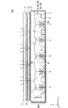
図1は、本実施の形態1における液晶表示装置100(面光源装置500を含む)の一例の構成を概略的に示す断面図である。図2は、面光源装置500の平面図である。図2中の線分ABにおける断面が図1に対応する。図2においては、図の見易さのために、導光棒6と第1、第2の光源4,5以外の記載を省略している。図3は、本実施の形態1における導光棒6の斜視図である。
Embodiment 1
FIG. 1 is a cross-sectional view schematically showing an example of the configuration of a liquid crystal display device 100 (including a surface light source device 500) according to the first embodiment. FIG. 2 is a plan view of the surface
図1に示すように、液晶表示装置100は、透過型の液晶パネル1、第1の光学シート2、第2の光学シート3および面光源装置500を備える。面光源装置500は、第2の光学シート3および第1の光学シート2を通して液晶パネル1の背面1bに光を照射する。
As shown in FIG. 1, the liquid
面光源装置500は、複数の第1の光源4と、複数の第2の光源5と、複数の導光棒6と、反射面7とを備える。第1の光源4は例えば青色LEDである。第2の光源5は、第1の光源4と異なる色の光を発する。第2の光源5は例えば緑色LEDである。導光棒6は、光入射面61から入射する第1、第2の光源4,5が発する光を面状の光に変換する。
The surface
反射面7は箱状である。箱状の反射面7は、複数の第1、第2の光源4,5および並列に配置された複数の導光棒6を収納する。反射面7において、面状の光が射出する側が開口されている。
The
図1に示すように、液晶パネル1、第1の光学シート2、第2の光学シート3、面光源装置500は、+z軸方向から−z軸方向にこの順に配置されている。
As shown in FIG. 1, the liquid crystal panel 1, the first optical sheet 2, the second optical sheet 3, and the surface
導光棒6は、透明樹脂(例えばアクリル、ポリカーボネートなど)を材料とする棒状の部材である。導光棒6は、第1、第2の光源4,5からの光の一部を全方位に拡散させつつ、その他の光を光の全反射により導光棒6内部に伝搬させ、単色である複数のLEDの光を混合する。ここでいう混合とは、入射位置の異なるそれぞれの光源からの光線の、液晶パネル1の背面1bへと到達した際における輝度分布が、ある程度均一化することを指す。
The
導光棒6は、複数の凸状体8と、複数の第1の凹部8aと、複数の第2の凹部9と、複数の第1のプリズム構造部11と、複数の第2のプリズム構造部10とを備える。
The
導光棒6の光入射面61は、導光棒6が延在する方向に沿った面である。複数の凸状体8は光入射面61に設けられる。凸状体8の頂面には、第1の凹部8aが設けられる。第1の凹部8aの内側には、第1の光源4または第2の光源5が配置される。
The
第1の凹部8aで、第1、第2の光源4,5を覆うことにより、光源から出射する光を効率的に導光棒6内部へ取り込むことが可能である。また、導光棒6に取り込まれた光は、導光棒6の内部で全反射を繰り返すため、導光棒6の端にまで第1、第2の光源4,5からの光が伝搬する。
By covering the first and second
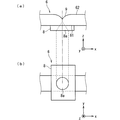
図4(a),(b)は導光棒6の部分的な断面図および底面図である。図4(a),(b)に示すように、第1の凹部8aは、円錐形状である。第1の凹部8aは、光源からの光を全方位へと拡散させる。また、図5(a),(b)に示すように、第1の凹部8aは円柱の上に円錐を積み重ねた形状であってもよい。また、図6(a),(b)に示すように、第1の凹部8aは四角柱の上に円錐を積み重ねた形状であってもよい。
FIGS. 4A and 4B are a partial cross-sectional view and a bottom view of the
図1および図3に示すように、複数の第2の凹部9は、光入射面61と対向する光出射面62に、第1の凹部8aに対向して設けられる。第2の凹部9は、第1の凹部8aに対して導光棒6の長手方向(x方向)に対称な曲線状の断面を有する。
As shown in FIGS. 1 and 3, the plurality of
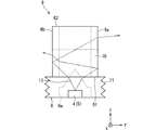
図7は、導光棒6の第1、第2の凹部8a,9における光の経路を説明する図である。図7に示すように、第1、第2の凹部8a,9を設けることにより、光源が発する光線のうち、発散角の小さい光線12が光源の直上に抜けることが軽減される。発散角の小さい光線12を、左右に均等な光量で導光棒6内部へと伝搬させることが可能となる。
FIG. 7 is a view for explaining the light path in the first and
図2および図3に示すように、複数の第2のプリズム構造部10は、光入射面61および光出射面62に接し、かつ、導光棒6の延在する方向(x方向)に沿った、対向する2つの面に設けられる。第2のプリズム構造部10は、導光棒6内に取り込まれた光線の全反射条件を意図的に崩し、導光棒6の外部に光線を射出するために設けられる。
As shown in FIGS. 2 and 3, the plurality of second
第2のプリズム構造部10は、導光棒6内を全反射により伝搬する光線の角度を変化させる。つまり、第2のプリズム構造部10の配置および形状によって、導光棒6の長手方向(x方向)において、導光棒6内部を伝搬する光の導光棒6外への光射出量と、光射出位置を制御することができる。
The
図8は、導光棒6の第1の凹部8aおよび第2のプリズム構造部10における光の経路を説明する図である。図8に示すように、第2のプリズム構造部10を設けることにより、光源からの光をy方向へ積極的に射出することができる。つまり、第2のプリズム構造部10を設けることにより、液晶パネル1の背面1bに光を照射する際、導光棒6の長手方向であるx方向だけでなく、短手方向であるy方向にも光を拡げることができる。
FIG. 8 is a view for explaining the light path in the
図3に示すように、第2のプリズム構造部10は、導光棒6の側面に対して凹形状の三角柱である。図3中の拡大図に示すように、第2のプリズム構造部10において、面10aがxz平面となす角度θaは、0°より大きく、90°より小さい範囲である。また、面10bがxz平面となす角度θbは、0°より大きく、90°より小さい範囲である。導光棒6の内部を−x方向に伝搬する光が、第2のプリズム構造部10の面10aで反射することにより、導光棒6の外部に光線が射出される。同様に、導光棒6の内部を+x方向に伝搬する光が、第2のプリズム構造部10の面10bで反射することにより、導光棒6の外部に光線が射出される。
As shown in FIG. 3, the second
図3に示すように、複数の凸状体8のそれぞれにおいて、第1のプリズム構造部11が設けられる。第1のプリズム構造部11は、凸状体8の±y方向側の対向する2つの側面に設けられる。第1のプリズム構造部11は、x方向に延在する三角柱の繰り返し構造である。図3中の拡大図に示すように、第1のプリズム構造部11を構成するそれぞれの三角柱において、面11a面がxz平面となす角度θaは、0°より大きく、90°より小さい範囲である。また、面11bがxz平面となす角度θbは、0°より大きく、90°より小さい範囲である。
As shown in FIG. 3, in each of the plurality of
図9は、導光棒6が凸状体8の側面に第1のプリズム構造部11を備えない場合における光線の経路を示す図である。図10は、導光棒6が凸状体8の側面に第1のプリズム構造部11を備える場合における光線の経路を示す図である。図9においては、光線13が導光棒6の外に拡散する際、凸状体8の平坦な側面により屈折し、z方向側に向けて射出される。一方、図10においては、光線13は導光棒6の側面に設けられた第1のプリズム構造部11において、出射する際の屈折角が大きくなり、±y方向側に向けて射出される。つまり、第1のプリズム構造部11を設けることにより、光源から射出される光をy方向に広げて、投射面における輝度をより均一化することが可能である。
FIG. 9 is a view showing a path of light in the case where the
なお、導光棒6の光入射面61にも第2のプリズム構造部10を設けてもよい。さらに、第2のプリズム構造部10は、連続して複数個並べてもよい。また、第2のプリズム構造部10は導光棒6の側面を貫通している必要はない。
The
また、第1、第2の光源4,5の光を導光棒6内部へ入射させるための構造である凸状体8は、導光棒6の光入射面61のどの位置に配置してもよい。
In addition, the
また、第2のプリズム構造部10は、導光棒6に対して凸構造であってもよい。さらに、第2のプリズム構造部10の形状は三角柱だけでなく、四角錐でもよい。
In addition, the second
また、本実施の形態1では、第1のプリズム構造部11を、凸状体8の側面のうち±y方向に面した対向する2つの側面に設けた。さらに、凸状体8の側面のうち±x方向に面した対向する2つの側面にも第1のプリズム構造部11を設けてもよい。また、第1のプリズム構造部11の形状は三角柱だけでなく、四角錐を並べた形状でもよい。
Further, in the first embodiment, the first
また、第1、第2のプリズム構造部11,10における三角柱の構造の大きさは任意に変えることができる。1つ1つの三角柱ごとに、その大きさや角度θa,θbが異なってもよい。
Further, the size of the triangular prisms in the first and second
また、本実施の形態1において、第1、第2の光源4,5はLEDであるとしたが、例えば、第1の光源4をLED、第2の光源5をレーザダイオードとするなど、発光特性の異なる光源としてもよい。
In the first embodiment, although the first and second
また、1本の導光棒6に対する光源は、2種類(2色)以上設置してもよい。また、一本の導光棒6に対する光源の個数は2つや3つ以上でもよい。
In addition, two or more types (two colors) of light sources for one
面光源装置500に配置される複数の導光棒6は、必要となる輝度や面光源の大きさに応じて個数を変更することが可能である。
The number of
<効果>
本実施の形態1における面光源装置500は、異なる色の光を発する複数種類の光源(第1、第2の光源4,5)と、光入射面61から入射する複数種類の光源が発する光を面状の光に変換する複数の導光棒6と、複数種類の光源および並列に配置された複数の導光棒6が収納され、面状の光が射出する側が開口された、箱状の反射面7と、を備え、導光棒6の光入射面61は、導光棒6が延在する方向(x方向)に沿った面であり、導光棒6は、光入射面61に設けられる複数の凸状体8と、複数の凸状体8の頂面に設けられる第1の凹部8aと、複数の凸状体8の頂面もしくは側面の少なくとも一方に設けられる第1のプリズム構造部11と、光入射面61と対向する光出射面62に第1の凹部8aに対向して設けられる複数の第2の凹部9と、光入射面61および光出射面62に接し、かつ、導光棒6の延在する方向に沿った、対向する2つの面に設けられる複数の第2のプリズム構造部10と、を備え、複数種類の光源のそれぞれは、第1の凹部8aの内側に配置され、第2の凹部9は、第1の凹部8aに対して導光棒6が延在する方向(x方向)に対称な曲線状の断面を有する。
<Effect>
In the surface
従って、導光棒6の光入射面61に複数の凸状体8を設け、各凸状体8に第1の凹部8aを設けてその内側に光源を配置することで、光源からの光を導光棒6の内部に効率的に導くことができる。また、第1の凹部8aに対して導光棒6が延在する方向(x方向)に対称な曲線状の断面を有する、第2の凹部9を設けることにより、光入射面61から導光棒6に入射した光線を導光棒6の延在方向に向けて反射することができる。つまり、光源からの光を、導光棒6の内部を全反射しながら伝搬する伝搬光とすることができる。
Therefore, by providing the plurality of
さらに、複数の第2のプリズム構造部10を設けることにより、導光棒6の内部を全反射しながら伝搬する伝搬光を、導光棒6の外部に射出することができる。また、凸状体8の側面に第1のプリズム構造部11を設けることにより、凸状体8の側面から出射する光を広い範囲に拡散させることができる。
Furthermore, by providing the plurality of second
以上のように、本実施の形態1において、各導光棒6は長方形状の均一な輝度分布を生成することが可能である。よって、均一な輝度分布を生成可能な導光棒6を複数並べることにより、均一な輝度分布をもった面光源装置を得ることが可能である。さらに、第1、第2の光源4,5が光入射面61のどの位置に存在しても、第1、第2のプリズム構造部11,10の形状、配置を調整することにより、各光源からの光による導光棒6出射時の輝度分布をほぼ同等に分布させることが可能であるため、色むらが発生しにくい。かつ、それぞれの光源は単色であるため、色再現範囲も広く保つことができる。
As described above, in the first embodiment, each
また、光源からの光を導光棒全体に伝搬させ、長手方向に伸長させ、かつ短手方向にも広く伸長させて用いているため、少ない光源数で広範囲を照射することが可能である。その結果、少数の導光棒6で面光源を作成可能となるため、バックライト用の部材を減らすことができる。
In addition, light from the light source is transmitted to the entire light guide rod, extended in the longitudinal direction, and extended widely in the short direction, so that it is possible to irradiate a wide range with a small number of light sources. As a result, a surface light source can be created with a small number of
また、本実施の形態1における面光源装置500において、第1の凹部8aは、円錐を含む形状である。
Moreover, in the surface
従って、第1の凹部8aを円錐形状とすることにより、光源からの光を全方位へと拡散させることが可能である。
Therefore, it is possible to diffuse the light from the light source in all directions by making the
また、本実施の形態1における面光源装置500において、第2のプリズム構造部10は三角柱である。
Further, in the surface
従って、三角柱を構成する面の角度を変化させることにより、導光棒6から出射する光線の角度を調整することが可能である。
Therefore, it is possible to adjust the angle of the light beam emitted from the
また、本実施の形態1における面光源装置500において、第2のプリズム構造部10は四角錐であってもよい。
Further, in the surface
従って、四角錐の形状を変化させることにより、導光棒6から出射する光線の角度を調整することが可能である。
Therefore, it is possible to adjust the angle of the light beam emitted from the
また、本実施の形態1における面光源装置500において、第2のプリズム構造部10は凹形状である。
Further, in the surface
従って、第2のプリズム構造部10を導光棒6に対して凹形状とすることにより、導光棒6の内部を伝搬する光線を効率的に反射することができる。
Therefore, by making the second
また、本実施の形態1における面光源装置500において、第2のプリズム構造部10は凸形状であってもよい。
Further, in the surface
従って、第2のプリズム構造部10を導光棒6に対して凸形状としても、導光棒6の内部を伝搬する光線を反射することができる。
Therefore, even if the second
また、本実施の形態1における面光源装置500において、第2のプリズム構造部10は、導光棒6の光入射面61にも設けてもよい。
Further, in the surface
従って、第2のプリズム構造部10を、導光棒6の光入射面61にも設けることにより、導光棒6の内部を全反射しながら伝搬する伝搬光を、導光棒6の外部に効率的に射出することができる。
Therefore, by providing the second
また、本実施の形態1における面光源装置500において、第1のプリズム構造部11は、凸状体8の側面のうち向かい合う2つの側面に設けられる。
Further, in the surface
従って、例えば、導光棒6の延在方向と直交する2つの側面に第1のプリズム構造部11を設けることにより、導光棒6の延在する方向だけでなく、導光棒6の幅方向にも光を拡散させることが可能である。
Therefore, for example, by providing the first
また、本実施の形態1における面光源装置500において、第1のプリズム構造部11は、凸状体8の側面のうちすべての面に設けられてもよい。
Further, in the surface
従って、凸状体8のすべての側面に第1のプリズム構造部11を設けることにより、光源から出射される光をより広い範囲に拡散することができる。
Therefore, by providing the first
また、本実施の形態1における面光源装置500において、第1のプリズム構造部11は、導光棒6の延在する方向に延在する複数の三角柱を含む。
Further, in the surface
従って、各三角柱を構成する面の角度を変化させることにより、凸状体8の側面から出射する光線の角度を調整することが可能である。
Therefore, it is possible to adjust the angle of the light beam emitted from the side surface of the
また、本実施の形態1における面光源装置500において、第1のプリズム構造部11は複数の四角錐を含んでもよい。
Further, in the surface
従って、三角柱の代わりに、複数の四角錐を設けた場合であっても、同様の効果を得ることが可能である。 Therefore, even when a plurality of quadrangular pyramids are provided instead of the triangular prism, it is possible to obtain the same effect.
また、本実施の形態1における面光源装置500において、複数種類の光源(即ち第1、第2の光源4,5)はLEDである。
Moreover, in the surface
従って、第1、第2の光源4,5を単色のLED光源とすることにより、面光源装置を液晶表示装置のバックライトとして用いた場合、液晶表示装置の色再現範囲を広く保つことができる。
Therefore, by using the first and second
また、本実施の形態1における面光源装置500において、複数種類の光源の少なくとも1種類の光源はレーザダイオードである。
Further, in the surface
従って、光源として直進性の高いレーザダイオードを用いた場合であっても、本実施の形態1における導光棒6により、輝度の均一な面状光源を実現することができる。
Therefore, even when a laser diode with high straightness is used as a light source, a planar light source with uniform brightness can be realized by the
また、本実施の形態1における液晶表示装置100は、面光源装置500と、面光源装置によって照射される光を利用して画像を表示する液晶パネル1と、を備える。
In addition, the liquid
従って、本実施の形態1によれば液晶表示装置100の表示品質を低下させることなく、面光源装置500の構成の簡素化が可能である。
Therefore, according to the first embodiment, the configuration of the surface
<実施の形態2>
図11は、本実施の形態2における導光棒6Aの斜視図である。本実施の形態2における導光棒6Aは、実施の形態1における導光棒6の第1のプリズム構造部11に代えて、第1のプリズム構造部11Aを備える。本実施の形態2における第1のプリズム構造部11A以外の構成は実施の形態1と同じである。
Second Embodiment
FIG. 11 is a perspective view of the
実施の形態1において、第1のプリズム構造部11は導光棒6が延在する方向(x方向)に延在する三角柱の繰り返し構造であった。一方、本実施の形態2において。第1のプリズム構造部11Aは、光入射面61に垂直方向(z方向)に延在する三角柱の繰り返し構造である。
In the first embodiment, the first
図11に示すように、第1のプリズム構造部11Aは、凸状体8の±y方向に面した2つの側面に設けられる。第1のプリズム構造部11Aはz方向に延在する三角柱の繰り返し構造である。図11中の拡大図に示すように、第1のプリズム構造部11Aを構成するそれぞれの三角柱において、面11Aa面がxz平面となす角度θaは、0°より大きく、90°より小さい範囲である。また、面11Abがxz平面となす角度θbは、0°より大きく、90°より小さい範囲である。
As shown in FIG. 11, the first
実施の形態1と同様に、面光源装置500の面状光において色むら、輝度むらを低減するためには、光源からの光を可能な限り導光棒6の内部に取り込み、伝搬させ、各光源からの光の輝度分布ができるだけ同じ分布となるように導光棒6外に出射することが好ましい。しかしながら、導光棒6内部に取り込まれず直接的な光として投射面へと到達する光も存在する。このような光についても、光源の位置によって偏りのない輝度分布となるように制御することが必要となる。
As in the first embodiment, in order to reduce color unevenness and brightness unevenness in planar light of the surface
本実施の形態2では、第1のプリズム構造部11Aを設けることにより、導光棒6Aの凸状体8におけるxz面内から射出する光の発散角が大きくなり、より遠くへ光を発散させることができるため、投射面での輝度むらを抑制する効果がある。
In the second embodiment, by providing the first
また、第1のプリズム構造部11Aは、凸状体8の±y方向側の側面だけでなく、±x方向側の側面に設けてもよい。さらに、第1のプリズム構造部11Aの形状は三角柱形状だけでなく、四角錐の繰り返しでもよい。
Further, the first
また、第1のプリズム構造部11Aにおける三角柱の構造の大きさは任意に変えることができ、1つ1つの三角柱の大きさや角度が違ってもよい。
In addition, the size of the triangular prism structure in the first
<効果>
本実施の形態2における面光源装置500において、第1のプリズム構造部11Aは、光入射面61に垂直な方向に延在する複数の三角柱を含む。
<Effect>
In the surface
従って、本実施の形態2では、導光棒6Aの凸状体8の側面に第1のプリズム構造部11Aを設けることにより、側面から射出する光の発散角が大きくなる。よって、投射面における輝度むらを抑制する効果がある。つまり、導光棒6Aは長方形状の均一な輝度分布を生成することが可能となる。均一な輝度分布を生成可能な複数の導光棒6Aを並べた面光源装置500は、均一な輝度分布をもった面光源として扱うことができる。さらに、光源がどの位置に存在しても、第1、第2のプリズム構造部11A,10の形状および配置を調整することにより、導光棒6Aから出射する各光源からの光の輝度分布をほぼ同等に分布させることが可能である。よって、色むらを抑制した面状光を得ることが可能である。
Therefore, in the second embodiment, by providing the first
<実施の形態3>
図12は、本実施の形態3における導光棒6Bの斜視図である。本実施の形態2における導光棒6Bは、実施の形態1の導光棒6の第1のプリズム構造部11に代えて、第1のプリズム構造部11Bを備える。本実施の形態2における第1のプリズム構造部11B以外の構成は実施の形態1と同じである。
Embodiment 3
FIG. 12 is a perspective view of the
第1のプリズム構造部11Bは凸状体8の頂面(即ち、凸状体8の−z方向側に面した面)に設けられる。第1のプリズム構造部11Bは、x方向に延在する複数の三角柱からなる。図12中の拡大図に示すように、第1のプリズム構造部11Bを構成するそれぞれの三角柱において、面11Ba面がxy平面となす角度θaは、0°より大きく、90°より小さい範囲である。また、面11Bbがxy平面となす角度θbは、0°より大きく、90°より小さい範囲である。 The first prism structure portion 11B is provided on the top surface of the convex body 8 (that is, the surface facing the −z direction side of the convex body 8). The first prism structure portion 11B is composed of a plurality of triangular prisms extending in the x direction. As shown in the enlarged view in FIG. 12, in each of the triangular prisms constituting the first prism structure portion 11B, the angle θa that the surface 11Ba surface makes with the xy plane is a range larger than 0 ° and smaller than 90 °. . Further, the angle θb that the surface 11Bb makes with the xy plane is a range larger than 0 ° and smaller than 90 °.
実施の形態1と同様に、面光源装置の面状光において色むら、輝度むらを低減するためには、光源からの光を可能な限り導光棒6の内部に取り込み、伝搬させ、各光源からの光の輝度分布ができるだけ同じ分布となるように導光棒6B外に出射することが好ましい。さらに、導光棒6B内部に取り込まれ、かつ凸状体8の頂面に伝搬してくる光は、凸状体8の近隣に射出されやすく、輝度むらの原因になりやすい。
As in the first embodiment, in order to reduce color unevenness and brightness unevenness in planar light of the surface light source device, light from the light source is taken into the inside of the
そこで、本実施の形態3では凸状体8の頂面に第1のプリズム構造部11Bを設けた。第1のプリズム構造部11Bを設けることにより、凸状体8の頂面に入射し、全反射して導光棒6内部に伝搬する光線、もしくは、凸状体8の頂面を透過して反射面7に反射してから導光棒6Bの外部に射出される光線のyz面内での方向を制御することができる。
Therefore, in the third embodiment, the first prism structure portion 11 B is provided on the top surface of the
つまり、導光棒6Bの凸状体8の頂面に反射した後xz面内もしくはyz面内から射出する光の発散角が大きくなり、より遠くへ光を発散させることができ、輝度分布が偏らないため、強度の高い直接光による投射面での輝度むらを抑制する効果がある。
That is, the angle of divergence of light emitted from within the xz plane or the yz plane after being reflected by the top surface of the
また、第1のプリズム構造部11Bの形状は三角柱形状だけでなく、四角錐の繰り返しでもよい。また、第1のプリズム構造部11Bにおける三角柱の構造の大きさは任意に変えることができ、1つ1つの三角柱の大きさや角度が違ってもよい。 Further, the shape of the first prism structure portion 11B is not limited to a triangular prism shape, and may be a repetition of a quadrangular pyramid. In addition, the size of the triangular prism structure in the first prism structure portion 11B can be arbitrarily changed, and the size and angle of each triangular prism may be different.
<効果>
本実施の形態3における面光源装置500において、第1のプリズム構造部11Bは、凸状体8の頂面に設けられる。
<Effect>
In the surface
従って、凸状体8の頂面に第1のプリズム構造部11Bを設けることにより、凸状体8の頂面に反射した後、凸状体8の側面から射出する光の発散角が大きくなる。よって、投射面における輝度むらを抑制する効果がある。つまり、導光棒6Bは長方形状の均一な輝度分布を生成することが可能となる。均一な輝度分布を生成可能な複数の導光棒6Bを並べた面光源装置500は、均一な輝度分布をもった面光源として扱うことができる。さらに、光源がどの位置に存在しても、第1、第2のプリズム構造部11B,10の形状および配置を調整することにより、導光棒6Bから出射する各光源からの光の輝度分布をほぼ同等に分布させることが可能である。よって、色むらを抑制した面状光を得ることが可能である。
Therefore, by providing the first prism structure portion 11B on the top surface of the
また、本実施の形態3における面光源装置500において、第1のプリズム構造部11Bは、導光棒6Bの延在する方向に延在する複数の三角柱を含む。
Further, in the surface
従って、各三角柱を構成する面の角度を変化させることにより、導光棒6Bから出射する光線の角度を調整することが可能である。
Therefore, it is possible to adjust the angle of the light beam emitted from the
<実施の形態4>
図13は、本実施の形態4における導光棒6Cの斜視図である。本実施の形態4における導光棒6Cは、実施の形態1の導光棒6の第1のプリズム構造部11に代えて、第1のプリズム構造部11Cをさらに備える。本実施の形態4において、第1のプリズム構造部11C以外の構成は実施の形態1と同じである。
Fourth Preferred Embodiment
FIG. 13 is a perspective view of a
本実施の形態4において、第1のプリズム構造部11Cは凸状体8の頂面に設けられる。第1のプリズム構造部11Cは、y方向に延在する三角柱の繰り返し構造である。図12中の拡大図に示すように、第1のプリズム構造部11Cを構成するそれぞれの三角柱において、面11Ca面がxy平面となす角度θaは、0°より大きく、90°より小さい範囲である。また、面11Cbがxy平面となす角度θbは、0°より大きく、90°より小さい範囲である。
In the fourth embodiment, the first
実施の形態1と同様に、面光源装置の面状光において色むら、輝度むらを低減するためには、光源からの光を可能な限り導光棒6の内部に取り込み、伝搬させ、各光源からの光の輝度分布ができるだけ同じ分布となるように導光棒6外に出射することが好ましい。さらに、導光棒6C内部に取り込まれ、かつ凸状体8の頂面に伝搬してくる光は、凸状体8の近隣に射出されやすく、輝度むらの原因になりやすい。
As in the first embodiment, in order to reduce color unevenness and brightness unevenness in planar light of the surface light source device, light from the light source is taken into the inside of the
そこで、本実施の形態4では凸状体8の頂面に第1のプリズム構造部11Cを設けた。第1のプリズム構造部11Cを設けることにより、凸状体8の頂面に入射し、全反射して導光棒6C内部に伝搬する光線、もしくは、凸状体8の頂面を透過して反射面7に反射してから導光棒6Cの外部に射出される光線のyz面内での方向を制御することができる。
Therefore, in the fourth embodiment, the first
つまり、導光棒6Cの凸状体8の頂面に反射した後、±y方向側の側面もしくは±x方向側の側面から射出する光の発散角が大きくなり、より遠くへ光を発散させることができ、輝度分布が偏らないため、強度の高い直接光による投射面での輝度むらを抑制する効果がある。
That is, after being reflected on the top surface of the
また、第1のプリズム構造部11Cの形状は三角柱形状だけでなく、四角錐の繰り返しでもよい。また、第1のプリズム構造部11Cにおける三角柱の構造の大きさは任意に変えることができ、1つ1つの三角柱の大きさや角度が違ってもよい。
Further, the shape of the first
<効果>
本実施の形態4における面光源装置500において、第1のプリズム構造部11Cは、凸状体8の頂面に設けられる。
<Effect>
In the surface
従って、凸状体8の頂面に第1のプリズム構造部11Cを設けることにより、凸状体8の頂面に反射した後、凸状体8の±y方向側の側面もしくは±x方向側の側面から射出する光の発散角が大きくなる。よって、投射面における輝度むらを抑制する効果がある。つまり、導光棒6Cは長方形状の均一な輝度分布を生成することが可能となる。均一な輝度分布を生成可能な複数の導光棒6Cを並べた面光源装置500は、均一な輝度分布をもった面光源として扱うことができる。さらに、光源がどの位置に存在しても、第1、第2のプリズム構造部11C,10の形状および配置を調整することにより、導光棒6Cから出射する各光源からの光の輝度分布をほぼ同等に分布させることが可能である。よって、色むらを抑制した面状光を得ることが可能である。
Accordingly, by providing the first
また、本実施の形態4における面光源装置500において、第1のプリズム構造部11Cは、導光棒6Cの延在する方向と直交する方向に延在する複数の三角柱を含む。
Further, in the surface
従って、各三角柱を構成する面の角度を変化させることにより、導光棒6Cから出射する光線の角度を調整することが可能である。
Therefore, it is possible to adjust the angle of the light beam emitted from the
<実施の形態5>
図14は、本実施の形態5における導光棒6Dの斜視図である。本実施の形態5における導光棒6Dは、実施の形態1の導光棒6の第1のプリズム構造部11に代えて、第1のプリズム構造部11Dを備える。本実施の形態5において、第1のプリズム構造部11B以外の構成は実施の形態1と同じである。
The Fifth Preferred Embodiment
FIG. 14 is a perspective view of a
第1のプリズム構造部11Dは、凸状体8の±y方向に面した対向する2つの側面に設けられる。第1のプリズム構造部11Dは、第1、第2領域11Da,11Dbから構成される。第1領域11Daは、導光棒6Dの延在する方向(x方向)に延在する複数の三角柱から構成される。第2領域11Dbは、導光棒6Dの光入射面61に垂直な方向(z方向)に延在する複数の三角柱から構成される。2つの第1領域11Daの間に第2領域11Dbが挟まれている。
The first
実施の形態1と同様に、面光源装置500において色むら、輝度むらを低減するためには、第1、第2の光源4,5から出射される光が単色であるため、可能な限り導光棒内に光線を取り込み、伝搬させ、各光源からの光の輝度分布ができるだけ同じ分布となるように導光棒外に出射することが好ましい。導光棒内に取り込まれず直接的な光として投射面へと到達する光についても、光源の位置によって偏りのない輝度分布に制御することが必要となる。
As in the first embodiment, in order to reduce color unevenness and brightness unevenness in the surface
第1、第2領域11Da,11Dbからなる第1のプリズム構造部11Dを凸状体8の側面に設けることにより、凸状体8の側面から導光棒6Dの外部に射出される光線のyz面内での方向を制御することができる。また、凸状体8の側面から導光棒6Dの外部に射出される光線のxy面内での方向も制御することができる。
By providing the first
よって、凸状体8の頂面において反射した後凸状体8の側面から射出する光の発散角が大きくなり、より遠くへ光を発散させることができる。発散光の輝度分布が偏らないため、強度の高い直接光による投射面での輝度むらを抑制する効果がある。
Therefore, the divergence angle of the light emitted from the side surface of the
また、第1のプリズム構造部11Dは、凸状体8の±y方向側の側面だけでなく、±x方向側の側面に設けてもよい。さらに、凸状体8の頂面に第1のプリズム構造部11Dを設けてもよい。この場合、第1のプリズム構造部11Dは、第1の凹部8aの開口を避けて設けられる。
Further, the first
さらに、第1のプリズム構造部11Dの形状は三角柱形状だけでなく、四角錐の繰り返しでもよい。
Furthermore, the shape of the first
また、第1のプリズム構造部11Dにおける三角柱の構造の大きさは任意に変えることができ、1つ1つの三角柱の大きさや角度が違ってもよい。
Further, the size of the triangular prism structure in the first
また、第1のプリズム構造部11Dにおいて、第1領域11Daと第2領域11Dbの面積の割合は、目指す輝度分布に応じて任意で変更可能である。
Further, in the first
<効果>
本実施の形態5における面光源装置500において、第1のプリズム構造部11Dは、延在する方向の異なる複数の三角柱を含む。
<Effect>
In the surface
従って、凸状体8の側面において、同一面内に延在方向の異なる複数の三角柱を設けることにより、側面を通過する光の発散方向の偏りを低減させることができる。よって、投射面における輝度むらを抑制する効果がある。つまり、導光棒6Dは長方形状の均一な輝度分布を生成することが可能となる。均一な輝度分布を生成可能な複数の導光棒6Aを並べた面光源装置500は、均一な輝度分布をもった面光源として扱うことができる。さらに、光源がどの位置に存在しても、第1、第2のプリズム構造部11D,10の形状および配置を調整することにより、導光棒6Aから出射する各光源からの光の輝度分布をほぼ同等に分布させることが可能である。よって、色むらを抑制した面状光を得ることが可能である。
Therefore, by providing a plurality of triangular prisms having different extending directions in the same plane on the side surface of the
なお、本発明は、その発明の範囲内において、各実施の形態を自由に組み合わせたり、各実施の形態を適宜、変形、省略することが可能である。 In the present invention, within the scope of the invention, each embodiment can be freely combined, or each embodiment can be appropriately modified or omitted.
1 液晶パネル、1a 映像表示面、1b 背面、2 第1の光学シート、3 第2の光学シート、4 第1の光源、5 第2の光源、6,6A,6B,6C,6D 導光棒、61 光入射面、62 光出射面、7 反射面、8 凸状体、8a 第1の凹部、9 第2の凹部、10 第2のプリズム構造部、11,11A,11B,11C 第1のプリズム構造部、12,13 光線、100 液晶表示装置、500 面光源装置。 DESCRIPTION OF SYMBOLS 1 liquid crystal panel, 1a image display surface, 1b back surface, 2 1st optical sheet, 3 2nd optical sheet, 4 1st light source, 5 2nd light source, 6, 6A, 6B, 6C, 6D light guide rod , 61 light incident surface, 62 light emitting surface, 7 reflecting surface, 8 convex body, 8a first recess, 9 second recess, 10 second prism structure, 11, 11A, 11B, 11C first Prism structure part, 12, 13 rays, 100 liquid crystal display device, 500 surface light source device.
Claims (21)
光入射面から入射する前記複数種類の光源が発する光を面状の光に変換する複数の導光棒と、
前記複数種類の光源および並列に配置された前記複数の導光棒が収納され、前記面状の光が射出する側が開口された、箱状の反射面と、
を備え、
前記導光棒の前記光入射面は、当該導光棒が延在する方向に沿った面であり、
前記導光棒は、
前記光入射面に設けられる複数の凸状体と、
前記複数の凸状体の頂面に設けられる第1の凹部と、
前記複数の凸状体の頂面または側面の少なくとも一方に設けられる第1のプリズム構造部と、
前記光入射面と対向する光出射面に前記第1の凹部に対向して設けられる複数の第2の凹部と、
前記光入射面および前記光出射面に接し、かつ、前記導光棒の延在する方向に沿った、対向する2つの面に設けられる複数の第2のプリズム構造部と、
を備え、
前記複数種類の光源のそれぞれは、前記第1の凹部の内側に、1つの前記第1の凹部に対して1つの割合で配置され、
前記第2の凹部は、前記第1の凹部に対して前記導光棒が延在する方向に対称な曲線状の断面を有する、
面光源装置。 Multiple types of light sources emitting light of different colors,
A plurality of light guide rods for converting light emitted from the plurality of types of light sources incident from the light incident surface into planar light;
A box-shaped reflecting surface that accommodates the plurality of types of light sources and the plurality of light guide rods arranged in parallel, and the side from which the planar light is emitted is opened;
Equipped with
The light incident surface of the light guiding rod is a surface along a direction in which the light guiding rod extends,
The light guide bar is
A plurality of convex bodies provided on the light incident surface;
A first recess provided on top surfaces of the plurality of convex bodies;
A first prism structure provided on at least one of the top surface or the side surface of the plurality of convex bodies;
A plurality of second concave portions provided on the light emitting surface facing the light incident surface so as to face the first concave portion;
A plurality of second prism structure portions provided on two opposing surfaces in contact with the light incident surface and the light emission surface and along the extending direction of the light guide bar;
Equipped with
Each of the plurality of types of light sources is arranged inside the first recess at a ratio of one to the first recess ,
The second recess has a curved cross section that is symmetrical in the direction in which the light guide rod extends with respect to the first recess.
Surface light source device.
請求項1に記載の面光源装置。 The first recess is shaped to include a cone,
The surface light source device according to claim 1.
請求項1または請求項2に記載の面光源装置。 The second prismatic structure is a triangular prism.
The surface light source device of Claim 1 or Claim 2.
請求項1または請求項2に記載の面光源装置。 The second prism structure portion is a quadrangular pyramid.
The surface light source device of Claim 1 or Claim 2.
請求項1から請求項4のいずれか一項に記載の面光源装置。 The second prismatic structure has a concave shape,
The surface light source device as described in any one of Claims 1-4.
請求項1から請求項4のいずれか一項に記載の面光源装置。 The second prismatic structure is convex.
The surface light source device as described in any one of Claims 1-4.
請求項1から請求項6のいずれか一項に記載の面光源装置。 The second prism structure portion is also provided on the light incident surface of the light guide bar.
The surface light source device as described in any one of Claims 1-6.
請求項1から請求項7のいずれか一項に記載の面光源装置。 The first prism structure portion is provided on two opposite side surfaces of the side surfaces of the convex body.
The surface light source device as described in any one of Claims 1-7.
請求項1から請求項7のいずれか一項に記載の面光源装置。 The first prism structure portion is provided on all of the side surfaces of the convex body.
The surface light source device as described in any one of Claims 1-7.
請求項1から請求項7のいずれか一項に記載の面光源装置。 The first prism structure portion is provided on the top surface of the convex body.
The surface light source device as described in any one of Claims 1-7.
請求項8から請求項10のいずれか一項に記載の面光源装置。 The first prism structure includes a plurality of triangular prisms extending in a direction in which the light guide rod extends.
The surface light source device as described in any one of Claims 8-10.
請求項8または請求項9に記載の面光源装置。 The first prismatic structure includes a plurality of triangular prisms extending in a direction perpendicular to the incident surface.
The surface light source device of Claim 8 or Claim 9.
請求項10に記載の面光源装置。 The first prism structure includes a plurality of triangular prisms extending in a direction orthogonal to the extending direction of the light guide bar.
The surface light source device according to claim 10.
請求項8から請求項10のいずれか一項に記載の面光源装置。 The first prism structure includes a plurality of triangular prisms having different extending directions.
The surface light source device as described in any one of Claims 8-10.
請求項8から請求項10のいずれか一項に記載の面光源装置。 The first prismatic structure includes a plurality of quadrangular pyramids.
The surface light source device as described in any one of Claims 8-10.
請求項1から請求項15のいずれか一項に記載の面光源装置。 The plurality of types of light sources are LEDs,
The surface light source device as described in any one of Claims 1-15.
請求項1から請求項15のいずれか一項に記載の面光源装置。 At least one light source of the plurality of light sources is a laser diode.
The surface light source device as described in any one of Claims 1-15.
前記面光源装置によって照射される光を利用して画像を表示する液晶パネルと、
を備える、
液晶表示装置。 The surface light source device according to any one of claims 1 to 17;
A liquid crystal panel that displays an image using light emitted by the surface light source device;
Equipped with
Liquid crystal display device.
光入射面から入射する前記複数種類の光源が発する光を面状の光に変換する複数の導光棒と、 A plurality of light guide rods for converting light emitted from the plurality of types of light sources incident from the light incident surface into planar light;
前記複数種類の光源および並列に配置された前記複数の導光棒が収納され、前記面状の光が射出する側が開口された、箱状の反射面と、 A box-shaped reflecting surface that accommodates the plurality of types of light sources and the plurality of light guide rods arranged in parallel, and the side from which the planar light is emitted is opened;
を備え、 Equipped with
前記導光棒の前記光入射面は、当該導光棒が延在する方向に沿った面であり、 The light incident surface of the light guiding rod is a surface along a direction in which the light guiding rod extends,
前記導光棒は、 The light guide bar is
前記光入射面に設けられる複数の凸状体と、 A plurality of convex bodies provided on the light incident surface;
前記複数の凸状体の頂面に設けられる第1の凹部と、 A first recess provided on top surfaces of the plurality of convex bodies;
前記複数の凸状体の頂面または側面の少なくとも一方に設けられる第1のプリズム構造部と、 A first prism structure provided on at least one of the top surface or the side surface of the plurality of convex bodies;
前記光入射面と対向する光出射面に前記第1の凹部に対向して設けられる複数の第2の凹部と、 A plurality of second concave portions provided on the light emitting surface facing the light incident surface so as to face the first concave portion;
前記光入射面および前記光出射面に接し、かつ、前記導光棒の延在する方向に沿った、対向する2つの面に設けられる複数の第2のプリズム構造部と、 A plurality of second prism structure portions provided on two opposing surfaces in contact with the light incident surface and the light emission surface and along the extending direction of the light guide bar;
を備え、 Equipped with
前記複数種類の光源のそれぞれは、前記第1の凹部の内側に配置され、 Each of the plurality of types of light sources is disposed inside the first recess,
前記第2の凹部は、前記第1の凹部に対して前記導光棒が延在する方向に対称な曲線状の断面を有し、 前記第1のプリズム構造部は、前記凸状体の側面のうち向かい合う2つの側面に設けられる、 The second concave portion has a curved cross section symmetrical to the first concave portion in the direction in which the light guide rod extends, and the first prism structure portion is a side surface of the convex body Provided on two opposite sides of the
面光源装置。Surface light source device.
光入射面から入射する前記複数種類の光源が発する光を面状の光に変換する複数の導光棒と、 A plurality of light guide rods for converting light emitted from the plurality of types of light sources incident from the light incident surface into planar light;
前記複数種類の光源および並列に配置された前記複数の導光棒が収納され、前記面状の光が射出する側が開口された、箱状の反射面と、 A box-shaped reflecting surface that accommodates the plurality of types of light sources and the plurality of light guide rods arranged in parallel, and the side from which the planar light is emitted is opened;
を備え、 Equipped with
前記導光棒の前記光入射面は、当該導光棒が延在する方向に沿った面であり、 The light incident surface of the light guiding rod is a surface along a direction in which the light guiding rod extends,
前記導光棒は、 The light guide bar is
前記光入射面に設けられる複数の凸状体と、 A plurality of convex bodies provided on the light incident surface;
前記複数の凸状体の頂面に設けられる第1の凹部と、 A first recess provided on top surfaces of the plurality of convex bodies;
前記複数の凸状体の頂面または側面の少なくとも一方に設けられる第1のプリズム構造部と、 A first prism structure provided on at least one of the top surface or the side surface of the plurality of convex bodies;
前記光入射面と対向する光出射面に前記第1の凹部に対向して設けられる複数の第2の凹部と、 A plurality of second concave portions provided on the light emitting surface facing the light incident surface so as to face the first concave portion;
前記光入射面および前記光出射面に接し、かつ、前記導光棒の延在する方向に沿った、対向する2つの面に設けられる複数の第2のプリズム構造部と、 A plurality of second prism structure portions provided on two opposing surfaces in contact with the light incident surface and the light emission surface and along the extending direction of the light guide bar;
を備え、 Equipped with
前記複数種類の光源のそれぞれは、前記第1の凹部の内側に配置され、 Each of the plurality of types of light sources is disposed inside the first recess,
前記第2の凹部は、前記第1の凹部に対して前記導光棒が延在する方向に対称な曲線状の断面を有し、 The second recess has a curved cross section that is symmetrical in a direction in which the light guide bar extends with respect to the first recess,
前記第1のプリズム構造部は、前記凸状体の側面のうちすべての面に設けられる、 The first prism structure portion is provided on all of the side surfaces of the convex body.
面光源装置。Surface light source device.
光入射面から入射する前記複数種類の光源が発する光を面状の光に変換する複数の導光棒と、 A plurality of light guide rods for converting light emitted from the plurality of types of light sources incident from the light incident surface into planar light;
前記複数種類の光源および並列に配置された前記複数の導光棒が収納され、前記面状の光が射出する側が開口された、箱状の反射面と、 A box-shaped reflecting surface that accommodates the plurality of types of light sources and the plurality of light guide rods arranged in parallel, and the side from which the planar light is emitted is opened;
を備え、 Equipped with
前記導光棒の前記光入射面は、当該導光棒が延在する方向に沿った面であり、 The light incident surface of the light guiding rod is a surface along a direction in which the light guiding rod extends,
前記導光棒は、 The light guide bar is
前記光入射面に設けられる複数の凸状体と、 A plurality of convex bodies provided on the light incident surface;
前記複数の凸状体の頂面に設けられる第1の凹部と、 A first recess provided on top surfaces of the plurality of convex bodies;
前記複数の凸状体の頂面または側面の少なくとも一方に設けられる第1のプリズム構造部と、 A first prism structure provided on at least one of the top surface or the side surface of the plurality of convex bodies;
前記光入射面と対向する光出射面に前記第1の凹部に対向して設けられる複数の第2の凹部と、 A plurality of second concave portions provided on the light emitting surface facing the light incident surface so as to face the first concave portion;
前記光入射面および前記光出射面に接し、かつ、前記導光棒の延在する方向に沿った、対向する2つの面に設けられる複数の第2のプリズム構造部と、 A plurality of second prism structure portions provided on two opposing surfaces in contact with the light incident surface and the light emission surface and along the extending direction of the light guide bar;
を備え、 Equipped with
前記複数種類の光源のそれぞれは、前記第1の凹部の内側に配置され、 Each of the plurality of types of light sources is disposed inside the first recess,
前記第2の凹部は、前記第1の凹部に対して前記導光棒が延在する方向に対称な曲線状の断面を有し、 The second recess has a curved cross section that is symmetrical in a direction in which the light guide bar extends with respect to the first recess,
前記第1のプリズム構造部は、前記凸状体の前記頂面に設けられる、 The first prism structure portion is provided on the top surface of the convex body.
面光源装置。Surface light source device.
Priority Applications (1)
| Application Number | Priority Date | Filing Date | Title |
|---|---|---|---|
| JP2015048205A JP6512879B2 (en) | 2015-03-11 | 2015-03-11 | Surface light source device and liquid crystal display device |
Applications Claiming Priority (1)
| Application Number | Priority Date | Filing Date | Title |
|---|---|---|---|
| JP2015048205A JP6512879B2 (en) | 2015-03-11 | 2015-03-11 | Surface light source device and liquid crystal display device |
Publications (3)
| Publication Number | Publication Date |
|---|---|
| JP2016170883A JP2016170883A (en) | 2016-09-23 |
| JP2016170883A5 JP2016170883A5 (en) | 2018-03-01 |
| JP6512879B2 true JP6512879B2 (en) | 2019-05-15 |
Family
ID=56982592
Family Applications (1)
| Application Number | Title | Priority Date | Filing Date |
|---|---|---|---|
| JP2015048205A Expired - Fee Related JP6512879B2 (en) | 2015-03-11 | 2015-03-11 | Surface light source device and liquid crystal display device |
Country Status (1)
| Country | Link |
|---|---|
| JP (1) | JP6512879B2 (en) |
Family Cites Families (10)
| Publication number | Priority date | Publication date | Assignee | Title |
|---|---|---|---|---|
| JPH1020125A (en) * | 1996-06-28 | 1998-01-23 | Nitto Denko Corp | Surface light source device and liquid crystal display device |
| JP2004025817A (en) * | 2002-06-21 | 2004-01-29 | Sakari:Kk | Method for manufacturing photo-conductive board |
| TWI282017B (en) * | 2004-05-28 | 2007-06-01 | Epistar Corp | Planar light device |
| US20080247722A1 (en) * | 2005-09-19 | 2008-10-09 | Koninklijke Philips Electronics, N.V. | Waveguide and Lighting Device |
| JP4846561B2 (en) * | 2005-12-27 | 2011-12-28 | 昭和電工株式会社 | Light guide member, surface light source device and display device |
| JP5033545B2 (en) * | 2007-09-05 | 2012-09-26 | 株式会社日立製作所 | Video display device |
| CN102667323A (en) * | 2009-12-23 | 2012-09-12 | 夏普株式会社 | Light guiding body, light guiding unit, light guiding package, lighting device, and display device |
| WO2012105314A1 (en) * | 2011-02-04 | 2012-08-09 | コニカミノルタオプト株式会社 | Illuminating device |
| JP2013033622A (en) * | 2011-08-02 | 2013-02-14 | Stanley Electric Co Ltd | Lamp fitting |
| JP2014212079A (en) * | 2013-04-19 | 2014-11-13 | 株式会社エス・ケー・ジー | Light guide plate and lighting fixture having light guide plate |
-
2015
- 2015-03-11 JP JP2015048205A patent/JP6512879B2/en not_active Expired - Fee Related
Also Published As
| Publication number | Publication date |
|---|---|
| JP2016170883A (en) | 2016-09-23 |
Similar Documents
| Publication | Publication Date | Title |
|---|---|---|
| JP5259296B2 (en) | Planar illumination device and liquid crystal display device using the same | |
| KR101427503B1 (en) | Planar light source device and liquid crystal display apparatus | |
| JP5738742B2 (en) | Surface light source device | |
| JP5940157B2 (en) | Surface light source device and liquid crystal display device | |
| JP6391360B2 (en) | Surface light source device and liquid crystal display device | |
| JP6358894B2 (en) | Surface light source device and liquid crystal display device | |
| WO2012017613A1 (en) | Surface light-source apparatus and liquid crystal display apparatus | |
| JP2011238484A (en) | Backlight device and liquid crystal display | |
| JP6358895B2 (en) | Surface light source device and liquid crystal display device | |
| JPWO2009072296A1 (en) | Planar illumination device and liquid crystal display device using the same | |
| JP2011228078A (en) | Backlight device and liquid crystal display device | |
| JP2016081807A (en) | Planar light source device and liquid crystal device | |
| US9715057B2 (en) | Surface light source device and liquid crystal display device | |
| JP5706328B2 (en) | LIGHT EMITTING ELEMENT AND DISPLAY DEVICE USING THE SAME | |
| JP6512879B2 (en) | Surface light source device and liquid crystal display device | |
| WO2016002883A1 (en) | Illumination device and display device | |
| JP2016184564A (en) | Surface light source device and liquid crystal display unit | |
| JP2011258458A (en) | Backlight device and liquid crystal display device | |
| JP2014164833A (en) | Surface light source device and liquid crystal display device | |
| JP2012169120A (en) | Planar lighting device | |
| JP2008270145A (en) | Liquid crystal display device and backlight device | |
| JP2013080583A (en) | Plane light source device and display device having the same | |
| KR20160031621A (en) | Light generation member and display apparatus including the same | |
| JP5297243B2 (en) | Guide light | |
| TWI467280B (en) | Reflective display |
Legal Events
| Date | Code | Title | Description |
|---|---|---|---|
| A521 | Request for written amendment filed |
Free format text: JAPANESE INTERMEDIATE CODE: A523 Effective date: 20180119 |
|
| A621 | Written request for application examination |
Free format text: JAPANESE INTERMEDIATE CODE: A621 Effective date: 20180119 |
|
| A977 | Report on retrieval |
Free format text: JAPANESE INTERMEDIATE CODE: A971007 Effective date: 20181026 |
|
| A131 | Notification of reasons for refusal |
Free format text: JAPANESE INTERMEDIATE CODE: A131 Effective date: 20181106 |
|
| A521 | Request for written amendment filed |
Free format text: JAPANESE INTERMEDIATE CODE: A523 Effective date: 20181220 |
|
| TRDD | Decision of grant or rejection written | ||
| A01 | Written decision to grant a patent or to grant a registration (utility model) |
Free format text: JAPANESE INTERMEDIATE CODE: A01 Effective date: 20190312 |
|
| A61 | First payment of annual fees (during grant procedure) |
Free format text: JAPANESE INTERMEDIATE CODE: A61 Effective date: 20190409 |
|
| R150 | Certificate of patent or registration of utility model |
Ref document number: 6512879 Country of ref document: JP Free format text: JAPANESE INTERMEDIATE CODE: R150 |
|
| LAPS | Cancellation because of no payment of annual fees |