JP6511469B2 - System and method for active stylus input recognition based on optics - Google Patents
System and method for active stylus input recognition based on opticsInfo
- Publication number
- JP6511469B2 JP6511469B2 JP2016555969A JP2016555969A JP6511469B2 JP 6511469 B2 JP6511469 B2 JP 6511469B2 JP 2016555969 A JP2016555969 A JP 2016555969A JP 2016555969 A JP2016555969 A JP 2016555969A JP 6511469 B2 JP6511469 B2 JP 6511469B2
- Authority
- JP
- Japan
- Prior art keywords
- light source
- detectors
- light
- electromagnetic wave
- layer
- Prior art date
- Legal status (The legal status is an assumption and is not a legal conclusion. Google has not performed a legal analysis and makes no representation as to the accuracy of the status listed.)
- Active
Links
Images


Classifications
-
- G—PHYSICS
- G06—COMPUTING; CALCULATING OR COUNTING
- G06F—ELECTRIC DIGITAL DATA PROCESSING
- G06F3/00—Input arrangements for transferring data to be processed into a form capable of being handled by the computer; Output arrangements for transferring data from processing unit to output unit, e.g. interface arrangements
- G06F3/01—Input arrangements or combined input and output arrangements for interaction between user and computer
- G06F3/03—Arrangements for converting the position or the displacement of a member into a coded form
- G06F3/033—Pointing devices displaced or positioned by the user, e.g. mice, trackballs, pens or joysticks; Accessories therefor
- G06F3/0354—Pointing devices displaced or positioned by the user, e.g. mice, trackballs, pens or joysticks; Accessories therefor with detection of 2D relative movements between the device, or an operating part thereof, and a plane or surface, e.g. 2D mice, trackballs, pens or pucks
- G06F3/03542—Light pens for emitting or receiving light
-
- G—PHYSICS
- G06—COMPUTING; CALCULATING OR COUNTING
- G06F—ELECTRIC DIGITAL DATA PROCESSING
- G06F3/00—Input arrangements for transferring data to be processed into a form capable of being handled by the computer; Output arrangements for transferring data from processing unit to output unit, e.g. interface arrangements
- G06F3/01—Input arrangements or combined input and output arrangements for interaction between user and computer
- G06F3/03—Arrangements for converting the position or the displacement of a member into a coded form
- G06F3/033—Pointing devices displaced or positioned by the user, e.g. mice, trackballs, pens or joysticks; Accessories therefor
- G06F3/0354—Pointing devices displaced or positioned by the user, e.g. mice, trackballs, pens or joysticks; Accessories therefor with detection of 2D relative movements between the device, or an operating part thereof, and a plane or surface, e.g. 2D mice, trackballs, pens or pucks
- G06F3/03545—Pens or stylus
-
- G—PHYSICS
- G06—COMPUTING; CALCULATING OR COUNTING
- G06F—ELECTRIC DIGITAL DATA PROCESSING
- G06F3/00—Input arrangements for transferring data to be processed into a form capable of being handled by the computer; Output arrangements for transferring data from processing unit to output unit, e.g. interface arrangements
- G06F3/01—Input arrangements or combined input and output arrangements for interaction between user and computer
- G06F3/03—Arrangements for converting the position or the displacement of a member into a coded form
- G06F3/041—Digitisers, e.g. for touch screens or touch pads, characterised by the transducing means
- G06F3/042—Digitisers, e.g. for touch screens or touch pads, characterised by the transducing means by opto-electronic means
- G06F3/0421—Digitisers, e.g. for touch screens or touch pads, characterised by the transducing means by opto-electronic means by interrupting or reflecting a light beam, e.g. optical touch-screen
-
- G—PHYSICS
- G06—COMPUTING; CALCULATING OR COUNTING
- G06F—ELECTRIC DIGITAL DATA PROCESSING
- G06F2203/00—Indexing scheme relating to G06F3/00 - G06F3/048
- G06F2203/041—Indexing scheme relating to G06F3/041 - G06F3/045
- G06F2203/04101—2.5D-digitiser, i.e. digitiser detecting the X/Y position of the input means, finger or stylus, also when it does not touch, but is proximate to the digitiser's interaction surface and also measures the distance of the input means within a short range in the Z direction, possibly with a separate measurement setup
-
- G—PHYSICS
- G06—COMPUTING; CALCULATING OR COUNTING
- G06F—ELECTRIC DIGITAL DATA PROCESSING
- G06F2203/00—Indexing scheme relating to G06F3/00 - G06F3/048
- G06F2203/041—Indexing scheme relating to G06F3/041 - G06F3/045
- G06F2203/04109—FTIR in optical digitiser, i.e. touch detection by frustrating the total internal reflection within an optical waveguide due to changes of optical properties or deformation at the touch location
Landscapes
- Engineering & Computer Science (AREA)
- General Engineering & Computer Science (AREA)
- Theoretical Computer Science (AREA)
- Human Computer Interaction (AREA)
- Physics & Mathematics (AREA)
- General Physics & Mathematics (AREA)
- Position Input By Displaying (AREA)
- Length Measuring Devices By Optical Means (AREA)
Description
本開示は包括的にはスタイラス技術に関し、より詳細には、光学に基づくアクティブスタイラス入力認識のためのシステムおよび方法に関する。 The present disclosure relates generally to stylus technology, and more particularly to systems and methods for active stylus input recognition based on optics.
タッチセンシティブデバイスによれば、一般的に、ユーザが、仮想ボタン、キー、バー、ディスプレイ、およびディスプレイデバイス上に表示される他の要素を含む、ユーザインターフェース(UI)によって多くの場合に指示される場所において、1つもしくは複数の指、スタイラスまたは他の物体を用いてタッチセンサパネルにタッチするか、またはその上方をホバリングすることによって、種々の機能を実行できるようになる。一般に、タッチスクリーンが、タッチセンサパネル上のタッチイベントおよびタッチイベントの位置、またはタッチセンサパネル上のホバーイベントまたはホバーイベントの位置を認識することができ、その後、コンピューティングデバイスが、イベントの時点で現れる表示に従ってタッチまたはホバーイベントを解釈することができ、その後、そのイベントに基づいて1つまたは複数の動作を実行することができる。 Touch-sensitive devices generally dictate the user in many cases through a user interface (UI), which includes virtual buttons, keys, bars, displays, and other elements displayed on the display device. At a location, various functions can be performed by touching or hovering over the touch sensor panel with one or more fingers, a stylus or other object. In general, the touch screen can recognize the position of touch events and touch events on the touch sensor panel, or the position of hover events or hover events on the touch sensor panel, and then the computing device at the time of the events The touch or hover event can be interpreted according to the indication that appears, and then one or more actions can be performed based on the event.
コンピューティングデバイス、モバイルデバイス、キオスクなどのデバイスは多くの場合にスタイラスを利用し、スタイラスを用いて、ユーザは、タッチスクリーンディスプレイ上のスタイラス入力を使用することによってデバイスとやりとりすることができる。スタイラスは、コンピューティングデバイスおよびモバイルデバイスにおける有効な入力デバイスであり、重要な差別化要因であることが実証されている。スタイラスによって、ユーザは、タッチスクリーンをタッチすることによって、またはタッチスクリーンの上方でスタイラスをホバリングすることによって、種々の機能を実行できるようになる。一般に、タッチスクリーンを備えるデバイスは、スタイラスを用いてタッチの位置を認識することができ、その後、タッチイベントの時点で現れる表示に従って個々に、または単一のジェスチャとして、タッチを解釈することができ、その後、タッチイベントに基づいて1つまたは複数の動作を実行することができる。しかしながら、数多くのスタイラス実施態様は、消費電力量が多く、費用がかかり、大きな面積に拡大するのが容易ではない。従来のスタイラスは多くの場合に、ドライブと静電容量式タッチセンサパネルの検知電極との間の電気力線を遮断するのに十分に大きな指サイズの丸みを帯びた先端を有する単なる導電性棒体である。 Devices such as computing devices, mobile devices, kiosks, and the like often utilize a stylus that allows a user to interact with the device by using stylus input on a touch screen display. The stylus is a valid input device in computing and mobile devices and has been demonstrated to be an important differentiator. The stylus allows the user to perform various functions by touching the touch screen or by hovering the stylus above the touch screen. In general, devices equipped with a touch screen can use the stylus to recognize the position of the touch, and can then interpret the touch individually or as a single gesture according to the indication that appears at the time of the touch event , And then one or more actions may be performed based on the touch event. However, many stylus implementations are power intensive, expensive and not easy to scale up to large areas. Conventional styluses are often simply conductive bars with finger-sized rounded tips that are large enough to block the field lines between the drive and the sensing electrodes of the capacitive touch sensor panel It is a body.
したがって、低電力および低コストのアクティブスタイラスに基づく入力認識が必要とされている。 Thus, there is a need for low power and low cost active stylus based input recognition.
光学に基づくアクティブスタイラス入力認識のためのシステムおよび方法を特定するいくつかの実施形態が説明される。 Several embodiments are described that identify systems and methods for active stylus input recognition based on optics.
いくつかの実施形態では、方法が、ユーザが扱うことができるアクティブ光源から、電磁波信号を平面層に向かって初期方向に放射することを含む。また、その方法は、平面層に対して周囲の場所に位置決めされる複数の検出器に向かって、電磁波信号を初期方向とは異なる1つまたは複数の横方向に変向させることを含む。その方法はさらに、複数の検出器において、変向後の電磁波信号を受信することを含む。その方法はさらに、複数の検出器において受信された変向後の電磁波信号に基づいて、ユーザ制御光源の位置を推定することを含む。 In some embodiments, the method includes emitting an electromagnetic wave signal towards the planar layer in an initial direction from an active light source that the user can handle. The method also includes deflecting the electromagnetic wave signal in one or more lateral directions different from the initial direction towards a plurality of detectors positioned at circumferential locations relative to the planar layer. The method further includes receiving, at the plurality of detectors, the post-turn electromagnetic signal. The method further includes estimating the position of the user controlled light source based on the transformed electromagnetic wave signals received at the plurality of detectors.
いくつかの実施形態では、電磁波信号はアクティブスタイラスデバイスから放射される。 In some embodiments, the electromagnetic wave signal is emitted from the active stylus device.
いくつかの実施形態では、電磁波信号は赤外光を含む。 In some embodiments, the electromagnetic wave signal comprises infrared light.
いくつかの実施形態では、複数の検出器は、変向後の電磁波信号の強度測定値を特定するように動作可能な複数の光検出器を含む。 In some embodiments, the plurality of detectors include a plurality of light detectors operable to identify an intensity measurement of the electromagnetic wave signal after deflection.
いくつかの実施形態では、推定するステップは、平面層に対するスタイラスデバイスの位置を特定することを含み、位置は強度測定値の関数である。 In some embodiments, the estimating step comprises identifying the position of the stylus device relative to the planar layer, the position being a function of the intensity measurement.
いくつかの実施形態では、平面層はディスプレイデバイス内の複数の層のうちの1つである。 In some embodiments, the planar layer is one of multiple layers in a display device.
いくつかの実施形態では、平面層は変向させるステップを実行するように動作可能な散乱板を含む。 In some embodiments, the planar layer includes a scattering plate operable to perform the turning step.
いくつかの実施形態では、装置が、ユーザが扱うことができるアクティブ光源から、初期方向に放射された電磁波信号を受信し、電磁波信号を初期方向とは異なる1つまたは複数の横方向に変向させるように動作可能な平面層を含む。その装置はさらに、平面層に対して周囲の場所に位置決めされ、変向後の電磁波信号を受信するように動作可能な複数の検出器を含む。その装置はさらに、複数の検出器に結合されるプロセッサを含み、プロセッサは、複数の検出器において受信された変向後の電磁波信号に基づいて、アクティブ光源の位置を推定するように構成される。 In some embodiments, the device receives an electromagnetic wave signal emitted in an initial direction from an active light source that can be handled by the user, and redirect the electromagnetic wave signal in one or more lateral directions different from the initial direction. Including a planar layer operable to cause The apparatus further includes a plurality of detectors positioned at circumferential locations with respect to the planar layer and operable to receive the redirected electromagnetic signal. The apparatus further includes a processor coupled to the plurality of detectors, wherein the processor is configured to estimate the position of the active light source based on the post-turn electromagnetic wave signals received at the plurality of detectors.
いくつかの実施形態では、装置が、ユーザが扱うことができるアクティブ光源から、電磁波信号を平面層に向かって初期方向に放射するための手段を含む。その装置はさらに、平面層に対して周囲の場所に位置決めされる複数の検出器に向かって、電磁波信号を初期方向とは異なる1つまたは複数の横方向に変向させるための手段を含む。その装置はさらに、複数の検出器において、変向後の電磁波信号を受信するための手段を含む。また、その装置は、複数の検出器において受信された変向後の電磁波信号に基づいて、ユーザ制御光源の位置を推定するための手段を含む。 In some embodiments, the apparatus includes means for emitting an electromagnetic wave signal in an initial direction towards the planar layer from an active light source that the user can handle. The apparatus further comprises means for deflecting the electromagnetic wave signal in one or more lateral directions different from the initial direction towards the plurality of detectors positioned at peripheral locations relative to the planar layer. The apparatus further includes means for receiving the redirected electromagnetic wave signal at the plurality of detectors. The apparatus also includes means for estimating the position of the user-controlled light source based on the transformed electromagnetic wave signals received at the plurality of detectors.
いくつかの実施形態では、プロセッサ可読命令を含むプロセッサ可読非一時的媒体が、プロセッサに、ユーザが扱うことができるアクティブ光源から、電磁波信号を平面層に向かって初期方向に放射させるように構成される。その命令はさらに、プロセッサに、平面層に対して周囲の場所に位置決めされる複数の検出器に向かって、電磁波信号を初期方向とは異なる1つまたは複数の横方向に変向させるように構成される。また、その命令はさらに、プロセッサに、複数の検出器において変向後の電磁波信号を受信させるように構成される。その命令はさらに、プロセッサに、複数の検出器において受信された変向後の電磁波信号に基づいて、ユーザ制御光源の位置を推定させるように構成される。 In some embodiments, a processor readable non-transitory medium containing processor readable instructions is configured to cause the processor to emit an electromagnetic wave signal in an initial direction towards the planar layer from an active light source that the user can handle. Ru. The instructions are further configured to cause the processor to deflect the electromagnetic wave signal in one or more lateral directions different from the initial direction towards the plurality of detectors positioned at peripheral locations relative to the planar layer. Be done. Also, the instructions are further configured to cause the processor to receive the redirected electromagnetic wave signal at the plurality of detectors. The instructions are further configured to cause the processor to estimate the position of the user-controlled light source based on the post-turn electromagnetic wave signals received at the plurality of detectors.
本開示の態様が例として示される。添付の図面において、同様の参照番号は類似の要素を示す。 Aspects of the present disclosure are illustrated by way of example. Like reference numerals indicate like elements in the accompanying drawings.
添付の図面に関して以下に説明される詳細な説明は、種々の構成を説明することを意図しており、本明細書において説明される概念を実践することができる唯一の構成を表すことは意図していない。詳細な説明は、種々の概念の完全な理解を与えるために具体的な詳細を含む。しかしながら、これらの概念がこれらの具体的な詳細なしに実践できることは当業者に明らかであろう。場合によっては、そのような概念を曖昧にすることを回避するために、よく知られている構造および構成要素がブロック図の形で示されている。 The detailed description set forth below in connection with the appended drawings is intended to illustrate various configurations and is intended to represent the only configuration capable of practicing the concepts described herein. Not. The detailed description includes specific details to provide a thorough understanding of the various concepts. However, it will be apparent to one skilled in the art that these concepts can be practiced without these specific details. In some instances, well known structures and components are shown in block diagram form in order to avoid obscuring such concepts.
ここで、スタイラス技術のいくつかの態様が、種々の装置および方法を参照しながら提示される。これらの装置および方法は、種々のブロック、モジュール、構成要素、回路、ステップ、プロセス、アルゴリズムなど(まとめて「要素」と呼ばれる)によって、以下の詳細な説明において説明され、添付の図面において図示される。これらの要素は、電子ハードウェア、コンピュータソフトウェア、またはそれらの任意の組合せを使用して実現することができる。そのような要素をハードウェアとして実現するか、またはソフトウェアとして実現するかは、特定の適用例およびシステム全体に課された設計制約によって決まる。 Here, some aspects of stylus technology are presented with reference to various devices and methods. These devices and methods are described in the following detailed description by various blocks, modules, components, circuits, steps, processes, algorithms, etc. (collectively referred to as "elements") and illustrated in the accompanying drawings. Ru. These elements can be implemented using electronic hardware, computer software, or any combination thereof. Whether such elements are implemented as hardware or software depends upon the particular application and design constraints imposed on the overall system.
例として、要素、もしくは要素の任意の部分、または要素の任意の組合せは、1つまたは複数のプロセッサを含む「処理システム」で実現することができる。プロセッサの例は、マイクロプロセッサ、マイクロコントローラ、デジタルシグナルプロセッサ(DSP)、フィールドプログラマブルゲートアレイ(FPGA)、プログラマブル論理デバイス(PLD)、ステートマシン、ゲート論理、個別ハードウェア回路、および本開示全体にわたって説明される種々の機能を実行するように構成された他の適切なハードウェアを含む。処理システム内の1つまたは複数のプロセッサは、ソフトウェアを実行することができる。ソフトウェアは、ソフトウェア、ファームウェア、ミドルウェア、マイクロコード、ハードウェア記述言語と呼ばれるか、または他の名称で呼ばれるかにかかわらず、命令、命令セット、コード、コードセグメント、プログラムコード、プログラム、サブプログラム、ソフトウェアモジュール、アプリケーション、ソフトウェアアプリケーション、ソフトウェアパッケージ、ルーチン、サブルーチン、オブジェクト、実行可能ファイル、実行スレッド、プロシージャ、機能などを意味するように広く解釈されるべきである。 By way of example, an element, or any portion of an element, or any combination of elements may be implemented on a “processing system” that includes one or more processors. Examples of processors are described in microprocessors, microcontrollers, digital signal processors (DSPs), field programmable gate arrays (FPGAs), programmable logic devices (PLDs), state machines, gate logic, discrete hardware circuits, and throughout this disclosure. And other suitable hardware configured to perform the various functions being performed. One or more processors in the processing system can execute the software. Software, whether called software, firmware, middleware, microcode, hardware description language or otherwise, is an instruction, instruction set, code, code segment, program code, program, subprogram, software It should be interpreted broadly to mean modules, applications, software applications, software packages, routines, subroutines, objects, executables, threads of execution, procedures, functions etc.
したがって、1つまたは複数の例示的な実施形態では、説明される機能は、ハードウェア、ソフトウェア、ファームウェア、またはそれらの任意の組合せで実現することができる。ソフトウェアにおいて実現される場合、機能は、コンピュータ可読媒体上の1つまたは複数の命令またはコードとして、記憶または符号化することができる。コンピュータ可読媒体は、コンピュータ記憶媒体を含む。記憶媒体は、コンピュータによってアクセスすることができる任意の入手可能な媒体とすることができる。限定ではなく例として、そのようなコンピュータ可読媒体は、RAM、ROM、EEPROM、CD-ROMもしくは他の光ディスク記憶装置、磁気ディスクス記憶装置もしくは他の磁気記憶デバイス、または、命令もしくはデータ構造の形態の所望のプログラムコードを搬送もしくは記憶するために使用することができ、コンピュータによってアクセスすることができる、任意の他の媒体を含むことができる。本明細書において用いられるときに、ディスク(disk)およびディスク(disc)は、コンパクトディスク(CD)、レーザーディスク(登録商標)、光ディスク、デジタル多用途ディスク(DVD)、およびフロッピーディスクを含み、ディスク(disk)は通常、磁気的にデータを再生し、一方、ディスク(disc)は、レーザーで光学的にデータを再生する。上記の組合せもコンピュータ可読媒体の範囲内に含まれるべきである。 Thus, in one or more exemplary embodiments, the functions described may be implemented in hardware, software, firmware, or any combination thereof. When implemented in software, the functions may be stored or encoded as one or more instructions or code on a computer readable medium. Computer readable media includes computer storage media. A storage media may be any available media that can be accessed by a computer. By way of example and not limitation, such computer readable media may be RAM, ROM, EEPROM, CD-ROM or other optical disk storage, magnetic disk storage or other magnetic storage device, or in the form of instructions or data structures. And any other medium that can be used to carry or store the desired program code and can be accessed by a computer. As used herein, discs and discs include compact discs (CDs), laser discs, optical discs, digital versatile discs (DVDs), and floppy discs. A disk normally reproduces data magnetically, while a disk optically reproduces data with a laser. Combinations of the above should also be included within the scope of computer readable media.
ここで論じられるのは、複数の光検出器からの光学測定値(たとえば、強度、飛行時間、角分解能を有する検出器など)を用いて、平面に対するアクティブ光源デバイスの位置を特定するデバイス内で実施される光学に基づくスタイラス技術である。入力認識デバイスは、限定はしないが、透明散乱板層および複数の光検出器を含む。光検出器は、透明散乱板層に対して周囲の場所に位置決めすることができる。透明散乱板層は、入力認識が利用されるデバイスのディスプレイの上方に載置される平面層とすることができる。ユーザがアクティブ光源デバイスを用いてデバイスとやりとりするとき、アクティブ光源デバイスは散乱板層に向かってIR光を放射する。散乱板層は、散乱板層に対して周囲の場所に位置する光検出器に向かって、光のうちの少なくともある量を横方向に変向させることができる。各光検出器における変向後の光の光強度Idiは、対応する光検出器までのアクティブ光源デバイスの距離diに直接関連する。この関係rdi = f(Idi)を用いて、アクティブ光源デバイスの位置を、個々の光検出器からの光強度測定値を用いることによって特定することができる。その後、入力認識デバイスのディスプレイに対するアクティブ光源デバイスの位置を、三角測量技法を用いて特定することができる。 As discussed herein, devices that use optical measurements (eg, intensity, time of flight, detectors with angular resolution, etc.) from multiple light detectors to locate active light source devices relative to a plane Optical based stylus technology implemented. The input recognition device includes, but is not limited to, a transparent scattering plate layer and a plurality of light detectors. The light detector can be positioned at a peripheral location relative to the transparent scattering plate layer. The transparent scattering plate layer can be a planar layer mounted above the display of the device where input recognition is utilized. When a user interacts with the device using an active light source device, the active light source device emits IR light towards the scattering plate layer. The scattering plate layer is capable of laterally redirecting at least some of the light towards a light detector located at a peripheral location relative to the scattering plate layer. The light intensity I di of the redirected light at each light detector is directly related to the distance d i of the active light source device to the corresponding light detector. Using this relationship r di = f (I di ), the position of the active light source device can be identified by using the light intensity measurements from the individual light detectors. The position of the active light source device relative to the display of the input recognition device can then be identified using triangulation techniques.
アクティブ光源デバイス
図1は、本発明の一実施形態による、アクティブ光源デバイス100の構成要素のブロック図である。アクティブ光源デバイス100は、発光ダイオード(LED)120と、メモリ150と、ジャイロスコープ160と、加速度計180とを含む。いくつかの実施形態では、アクティブ光源デバイス100は、アクティブ赤外線スタイラスデバイスとして機能するための構成要素を含むことができる。他の実施形態は、より多くの、より少ない、および/または異なる構成要素を含む場合があることは理解されよう。
Active Light Source Device FIG. 1 is a block diagram of the components of the active
いくつかの実施形態では、構成要素は、アクティブ光源デバイス100内に位置決めすることができるプリント回路基板(PCB)上に実装することができる。他の実施形態では、いくつかの構成要素がPCB上に実装される場合があり、他の構成要素は実装されない場合がある。
In some embodiments, the components can be mounted on a printed circuit board (PCB) that can be positioned within the active
プロセッサ110は、アクティブ光源デバイス100上で命令を実行するように動作可能な任意の汎用プロセッサとすることができる。プロセッサ110は、LED120、メモリ150、ジャイロスコープ160および加速度計180を含む、アクティブ光源デバイス100の他のユニットに結合される。いくつかの実施形態では、プロセッサ110は、アクティブ光源デバイス100の他のユニットからのデータを受信するように構成することができる。
LED120は、アクティブ光源デバイス100から光を放射するように構成される光源である。アクティブ光源デバイス100は、2つ以上のLED120を含むことができることを理解することができる。いくつかの実施形態では、LED120は、赤外線(IR)スペクトルのような、電磁スペクトルの非可視部分において放射することができる。
The
メモリ150は、プロセッサ110のための動作命令を記憶するように構成することができる。いくつかの実施形態では、メモリ150は、アクティブ光源デバイス100の他のユニットから受信されたデータを記憶するように構成することができる。メモリ150は任意の磁気、電子または光学メモリとすることができる。メモリ150は、任意の数のメモリモジュールを含む場合があることは理解されよう。メモリ150の一例は、ダイナミックランダムアクセスメモリ(DRAM)とすることができる。
いくつかの実施形態では、アクティブ光源デバイス100およびジャイロスコープ160とともに、1つまたは複数の加速度計180を設けることができる。加速度計180およびジャイロスコープ160は、アクティブ光源デバイス100の向きおよび/またはアクティブ光源デバイス100の任意の動きを特定する際に役に立つ場合がある。加速度計180およびジャイロスコープ160によって与えられる向きおよび動き情報は、入力認識デバイス200に対するアクティブ光源デバイス100の向きおよび動きを特定するために用いることができる。
In some embodiments, one or
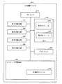
入力認識デバイス
図2は、本発明の一実施形態による、入力認識デバイス200の構成要素のブロック図である。入力認識デバイス200は、プロセッサ210と、第1の光検出器222と、第2の光検出器224と、第3の光検出器226と、第4の光検出器228と、コンピュータ可読媒体240と、ディスプレイ250とを含む。図2には4つの光検出器が示されるが、入力認識デバイス200は、任意の数の光検出器を含むことができることは理解されよう。いくつかの実施形態では、入力認識デバイス200は、タブレットコンピュータ、スマートフォンまたは他のコンピューティングデバイスとすることができ、図2に示される構成要素以外のさらなる構成要素を含むことができる。
Input Recognition Device FIG. 2 is a block diagram of the components of the
プロセッサ210は、入力認識デバイス200上で命令を実行するように動作可能な任意の汎用プロセッサとすることができる。プロセッサ210は、第1の光検出器222、第2の光検出器224、第3の光検出器226、第4の光検出器228、コンピュータ可読媒体240、およびディスプレイ250を含む、入力認識デバイス200の他のユニットに結合される。
ディスプレイ250は、ユーザに対して情報を表示する任意のデバイスとすることができる。複数の例は、LCD画面、CRTモニタ、または7セグメントディスプレイを含むことができる。いくつかの実施形態では、ディスプレイ250は、ユーザ入力を受信するように構成することができる。他の実施形態では、ディスプレイ250は、アクティブ光源デバイス100(図1)から受光された光を、複数の光検出器に向かって変向させるように動作可能な透明散乱板層を含むことができる。透明散乱板は、入力認識が利用されるディスプレイの表示層の上方に載置されるか、下方にあるか、隣接するか、またはその付近の任意の場所にある平面層とすることができる。ユーザがアクティブ光源デバイス100(図1)を用いて入力認識デバイス200とやりとりするとき、アクティブ光源デバイス100(図1)は、透明散乱板層に向かってIR光を放射することができる。
複数の光検出器(第1の光検出器222、第2の光検出器224、第3の光検出器226および第4の光検出器228)を、上記のように、ディスプレイ250内の透明散乱板層に対して周囲の場所に位置決めすることができる。散乱板は、光のうちの少なくともある量を、散乱板に対して周囲の場所に位置する光検出器に向かって横方向に変向させることができる。各光検出器における変向後の光の光強度Idiは、対応する光検出器までのスタイラスの距離diに直接関連する。この関係rdi = f(Idi)を用いて、アクティブ光源デバイス100(図1)の位置を、個々の光検出器(第1の光検出器222、第2の光検出器224、第3の光検出器226および第4の光検出器228)からの光強度測定値を用いることによって特定することができる。その後、入力認識デバイス200のディスプレイ250に対するアクティブ光源デバイス100(図1)の位置を、三角測量技法を用いて特定することができる。
The plurality of light detectors (the
メモリ230は任意の磁気、電子または光学メモリとすることができる。メモリ230は、2つのメモリモジュール、第1のモジュール232および第2のモジュール234を含む。メモリ230は、任意の数のメモリモジュールを含む場合があることは理解されよう。メモリ230の一例は、ダイナミックランダムアクセスメモリ(DRAM)とすることができる。
コンピュータ可読媒体240は、任意の磁気、電子、光学または他のコンピュータ可読記憶媒体とすることができる。コンピュータ可読記憶媒体240は、光測定モジュール242を含む、コードモジュールを含むコンピュータ可読コードを記憶する。
Computer
光測定モジュール242は、プロセッサ210によって実行されるときに、各光検出器(第1の光検出器222、第2の光検出器224、第3の光検出器226および第4の光検出器228)において受光されたIR光の強度を解析するコードを含む。いくつかの実施形態では、光測定モジュール242は、光検出器のいずれかにおいてIR光が実際に受光される時点も検出することができる。検出器のうちの1つにおいてIR光が受光されるのを検出すると、光検出モジュール242は、IR光を受光した光検出器においてIR光の強度を特定することができる。上記のように、入力認識デバイス200のディスプレイ250に対するアクティブ光源デバイス100の位置は、複数の光検出器において特定された光強度測定値に基づいて特定することができる。
The
図3は、本発明の一実施形態による、アクティブ光源デバイス100とやりとりする入力認識デバイス200を示す図である。アクティブ光源デバイス100は、入力認識デバイス200のユーザによって操作可能とすることができる。この特定の例では、入力認識デバイス200は、タブレットコンピュータとして示されるが、入力認識デバイス200は、任意のタイプのコンピューティングデバイスとすることができることは理解されよう。また、アクティブ光源デバイス100は、入力認識デバイス200のディスプレイ250に向かって赤外光を放射するように構成されるアクティブ光源デバイス100の端部においてLED120を含むことができる。アクティブ光源デバイス100の端部においてLED120が示される場合であっても、LED120は、アクティブ光源デバイス100内の他の場所に位置することができることは理解されよう。
FIG. 3 is a diagram illustrating an
ユーザがアクティブ光源デバイス100を用いて、入力認識デバイス200とやりとりするとき、LED120は、ディスプレイ250に向かって赤外光を放射することができる。入力認識デバイス200とやりとりするとき、ユーザはアクティブ光源デバイス100の端部でディスプレイ250に物理的にタッチすることができるか、またはディスプレイ250からの公称距離においてアクティブ光源デバイス100を使用することもできる。
The
上記のように、透明散乱板層(図示せず)がディスプレイ250の表示層を覆うことができる。しかしながら、透明散乱板層はディスプレイ250の表示層を直接覆う必要はなく、ディスプレイ250の表示層スタック内の任意の層に配置することができる。LED120がディスプレイ250に向かって赤外光を放射すると、透明散乱板層は、受光されたIR光のうちの少なくともある量を、散乱板層に対して周囲の場所に位置する複数の光検出器に向かって横方向に変向させることができる。各光検出器における変向後の光の光強度Idiは、対応する光検出器までのスタイラスの距離diに直接関連する。この関係rdi = f(Idi)を用いて、アクティブ光源デバイス100の位置を、個々の光検出器からの光強度測定値を用いることによって特定することができる。その後、ディスプレイ250に対するアクティブ光源デバイス100の位置を、三角測量技法を用いて特定することができる。
As noted above, a transparent scattering plate layer (not shown) can cover the display layer of the
ディスプレイ250に対する光源デバイス100の特定された位置情報を用いて、入力認識デバイス200のプロセッサ210(図2)はコマンドを実行することができる。たとえば、アクティブ光源デバイス100の位置が入力認識デバイス200上で実行されるソフトウェアによって表示され、ディスプレイ250上に表示される「OK」プロンプトの上方にあると判断される場合には、プロセッサ210(図2)は、ユーザによる「OK」プロンプトの容認に関連付けられるコマンドを実行することができる。
Using the identified position information of the
透明散乱板層
図4Aは、本発明の一実施形態による、入力認識デバイス200(図2)の透明散乱板層402の見下ろし図を示す図である。また、図4Aに示されるのは、アクティブ光源デバイス100(図1)である。上記のように、透明散乱板層402は、入力認識デバイス200のディスプレイ250(図2)の表示層の上方に載置されるか、下方にあるか、隣接するか、またはその付近の任意の場所にある平面層とすることができる。
Transparent Scattering Plate Layer FIG. 4A is a view looking down on the transparent
透明散乱板層402は、複数の光検出器404を含む。いくつかの実施形態では、複数の光検出器は、透明散乱板層402に対する周囲の場所に位置決めされる。図4Aに示される実施形態は4つの光検出器を示すが、透明散乱板層402に対する種々の場所に任意の数の光検出器を位置決めすることができる。複数の光検出器は、個々の光子の電気的効果を用いることによって、入射光を検出するか、または入射光に応答する任意のタイプのデバイスとすることができる。
The transparent
入力認識デバイス200とやりとりするために、ユーザがアクティブ光源デバイス100を使用すると、アクティブ光源デバイス100は、透明散乱板層402に向かってある方向にIR光408を放射することができる。透明散乱板層402は、アクティブ光源デバイス100から放射されるIR光408を変向させることができる散乱体要素を含むことができる。この例では、透明散乱板層402は、複数の光検出器404に向かってIR光408を変向させることができ、いくつかの実施形態では、光検出器は、透明散乱板層402に対して周囲の場所に位置決めされる。すなわち、IR光408は、アクティブ光源デバイス100から当初に放射された方向とは異なる方向に変向させることができる。
When a user uses the active
複数の光検出器404のそれぞれにおいて受光された変向後のIR光の強度は、各光検出器404に関連付けられる強度値(たとえば、id1、id2、id3およびid4)によって示されるように異なる場合がある。光測定モジュール242(図2)を介して各光検出器404における異なる強度値を特定すると、プロセッサ210は、アクティブ光源デバイス100の位置を特定することができる。いくつかの実施形態では、透明散乱板層402は、アクリル層から構成することができる。
The intensity of the redirected IR light received at each of the plurality of
図4Bは、本発明の一実施形態による、入力認識デバイス200(図2)の透明散乱板層402の断面図を示す図である。図4Bは、図4Aの同じ透明散乱板層402を断面図の観点から示す。図4Bに示されるのは、透明散乱板層402内の複数の散乱体410である。複数の散乱体410は、IR光がアクティブ光源デバイス100によって放射された方向以外の異なる方向にIR光408を変向させるように動作可能である。最終的には、複数の散乱体410によって散乱する光の少なくともある量が、複数の光検出器404に達することになる。
FIG. 4B illustrates a cross-sectional view of the transparent
図5は、本発明の一実施形態による、透明散乱板層402に対するアクティブ光源デバイス100の位置を特定することを例示する図である。IR光408が、上記のようにアクティブ光源デバイス100から放射されると、複数の光検出器404は、透明散乱板層402によって変向したIR光408を検出することができる。各光検出器404における変向後の光の光強度Idiは、対応する光検出器404までのアクティブ光源デバイス100の距離diに直接関連する。この関係rdi = f(Idi)を用いて、アクティブ光源デバイス100の位置を、個々の光検出器404からの光強度測定値を用いることによって特定することができる。たとえば、光検出器d1が強度Id1においてIR光408を受光するとき、アクティブ光源デバイス100は、光検出器d1の場所を中心にしてrd1 = f(Id1)の半径を有する円412の点に位置決めされると判断することができる。この例では、4つの各光検出器404における4つの光強度測定値に基づいて、4つすべての円412の交点において、透明散乱板層402に対するアクティブ光源デバイス100の位置が特定されるとの判断を行うことができる。4つの光検出器404が示されるが、入力認識デバイス200(図2)の透明散乱板層402において任意の数の光検出器404を使用できることは理解されよう。さらに、光検出器404は、透明散乱板層402上の任意の場所に位置することができることも理解されよう。
FIG. 5 is a diagram illustrating locating the active
精度およびジッタ結果
図6は、ディスプレイ250(図1)上の9つのアクティブ光源デバイス100(図1)における入力認識デバイス200(図2)の精度およびジッタ性能を示すグラフ610および表620を示す。図6の表620は、入力認識デバイス200(図2)を使用する実現可能性実験の結果を示す。その結果は、入力認識デバイス200(図2)が、現在の入力認識技術と匹敵する分解能を達成することを示す。精度およびジッタ測定値が、分解能を特徴付けるために使用された。精度は、計算されたアクティブ光源デバイス100(図1)位置と、ディスプレイ250(図1)上の実際のアクティブ光源デバイス100(図1)位置との間の差を特徴付ける。ジッタは、計算されたアクティブ光源デバイス100(図1)および実際のアクティブ光源デバイス100(図1)位置が固定されるときに、雑音に起因する異なる痕跡の間の計算されたアクティブ光源デバイス100(図1)位置の不確かさを特徴付ける。図6の左側にあるグラフ610は、入力認識デバイス200(図2)内の種々の説明された構成要素の位置を示す。正方形は光検出器404(図4)の場所を示し、プラス記号はアクティブ光源デバイス100(図1)の9つの実際の場所を示し、円はアクティブ光源デバイス100(図1)の対応する実際の位置におけるアクティブ光源デバイス100(図1)の計算された位置を示す。図6の右側にある表620は、9つのアクティブ光源デバイス100(図1)位置ごとの精度およびジッタ測定値を示す。見ることができるように、各位置の精度は0mm〜3mmの範囲に入り、ジッタ測定値は0mm〜0.3mmの範囲に入る。
Accuracy and Jitter Results FIG. 6 shows a
円錐ファセットを用いて光を変向させる
本発明の他の実施形態は異なる特徴を提供できることは理解されよう。たとえば、アクティブ光源デバイス100(図1)によって放射された光は、透明散乱板層の設計に基づいて異なるように散乱する場合がある。
It is understood that other embodiments of the present invention can provide different features by using a conical facet to redirect light. For example, light emitted by the active light source device 100 (FIG. 1) may scatter differently based on the design of the transparent scattering plate layer.
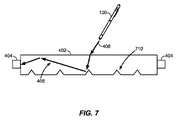
図7は、本発明の一実施形態による、円錐ファセット710のアレイによって光転向機構が供給される、透明散乱板層402の一実施形態の断面図を示す図である。すなわち、円錐ファセット710は、透明散乱板層402に向かってアクティブ光源デバイス100から放射されたIR光408を変向させる。光は、アクティブ光源デバイス100によって当初に放射されたIR光408の方向とは異なる方向に変向する場合がある。変向後のIR光408は、複数の光検出器404によって受光することができる。
FIG. 7 illustrates a cross-sectional view of one embodiment of a transparent
図7の実施形態は、入射する放射の一部を、その放射が透明散乱板層402内に閉じ込められるほど十分に大きな角度で次々に転向することができる散乱中心を示す。ファセットは、たとえば、エンボス加工技法によって形成することができる。ときには、この散乱は、等方的に変向する傾向があり、入射光の概ね50%を透明散乱板層402から外へ散乱させる場合もある。図7は、図5の実施形態の幾何学的形状を示しており、円錐ファセット710のアレイによって光転向機構が供給される。したがって、そのような円錐ファセット710に入射するIR光408のうちのより高いパーセンテージが、透明散乱板層402の中に閉じ込められる場合がある。ファセット710は、透明散乱板層402に積層されるか、または光学的に取り付けられる別の層内に含まれる場合もある。
The embodiment of FIG. 7 shows a scattering center that can divert some of the incident radiation at angles that are large enough so that the radiation is confined within the transparent
円錐ファセットは、光のうちのより多くの量を透明散乱板層402内に閉じ込めることができ、変向できるという利点を提供できることは理解されよう。
It will be appreciated that conical facets can provide the advantage that more of the light can be confined within the transparent
円形ファセットを用いて光を変向させる
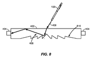
図8は、本発明の一実施形態による、透明散乱板層402の一実施形態の断面図を示す図であり、ファセットは円形であり、その曲率中心が入力認識デバイス200(図2)のディスプレイ250(図2)の表示パネルの中心と一致している。この例では、アクティブ光源デバイス100から放射され、垂直に入射するIR光408がファセット810に突き当たり、曲率中心から離れる1つの方向に転向する。この実施態様は、入射するIR光408の転向および/または収集の効率を高める。基本強度に基づくアルゴリズム機能を可能にするように、十分な平面内角度発散を確保するために、ファセット810上に少なくともいくつかの表面粗さが必要とされる場合があることは理解されよう。これは、透明散乱板層402の周辺部付近において重要な場合がある。
Redirecting Light Using Circular Facets FIG. 8 shows a cross-sectional view of one embodiment of a transparent
別の実施形態では、図8の実施形態の散乱粒子が蛍光粒子で置き換えられる。その場合に、入射するIR光408は蛍光粒子によって吸収される場合があり、それにより、蛍光粒子がすべての方向において、より長い波長の光を放射する。この光のうちのある量は、導光路内に閉じ込められ、検出するために透明散乱板層402の周辺部まで伝搬する。
In another embodiment, the scattering particles of the embodiment of FIG. 8 are replaced with fluorescent particles. In that case, the
円形ファセットは、放射されたIR光408を等方的にではなく、放射状に変向させることができ、結果として、効率が高くなることは理解されよう。 It will be appreciated that the circular facets can redirect the emitted IR light 408 radially rather than isotropically, resulting in higher efficiency.
光源高の推定
図9は、本発明の一実施形態による、IR光408を2つの異なる方向に放射するアクティブ光源デバイス100を示す。異なる高さにおいて、アクティブ光源デバイス100から放射されたIR光408は、光検出器404によって特定されるような、異なる強度において放射される場合がある。したがって、アクティブ光源デバイス100のz(高さ)位置を、図5に示される方法と同様に三角測量することができる。
Estimating Source Height FIG. 9 illustrates an
代替の光検出器
いくつかの実施形態では、光検出器404は、図4に示されるような個別の構成要素以外の構成要素とすることができる。たとえば、図10は、本発明の一実施形態による、透明散乱板層402内の一体型または埋込センサとして光検出器1004を示す。別の例では、図11は、本発明の一実施形態による、透明散乱板層402上に印刷されたセンサとして光検出器1104を示す。
Alternative Light Detectors In some embodiments, the
いくつかの実施形態では、散乱板は、光伝搬の方向を変更することができる任意の材料からなる任意の光転向機構を含むことができる。散乱板は、適切な基板材料を用いて可撓性にすることができる。 In some embodiments, the scattering plate can include any light turning mechanism of any material that can change the direction of light propagation. The scattering plate can be made flexible using a suitable substrate material.
いくつかの実施形態では、スタイラスおよび光検出器の波長は、電磁スペクトルの任意の範囲にあることができる。 In some embodiments, the wavelengths of the stylus and light detector can be in any range of the electromagnetic spectrum.
いくつかの実施形態では、スタイラスおよび光検出器は、周囲光からの干渉を低減するために調整することができる。 In some embodiments, the stylus and light detector can be adjusted to reduce interference from ambient light.
いくつかの実施形態では、光検出器による光学的測定が、角分解能(たとえば、ピンホール、スリットおよびレンズを通して)、飛行時間、または上記の組合せを検出することができる。たとえば、上記の強度測定値を飛行時間情報と組み合わせて、アクティブ光源デバイスの位置を特定することができる。別の例では、強度測定値は主要測定値として用いることができ、他の測定値(たとえば、角分解能または飛行時間)を主要測定値を補う補助測定値として用いることができる。 In some embodiments, optical measurement with a light detector can detect angular resolution (eg, through pinholes, slits and lenses), time of flight, or a combination of the above. For example, the intensity measurements described above may be combined with time of flight information to locate the active light source device. In another example, the intensity measurement can be used as a primary measurement, and other measurements (eg, angular resolution or time of flight) can be used as an auxiliary measurement to supplement the primary measurement.
いくつかの実施形態では、光学に基づくアクティブスタイラス入力認識システムは、たとえば、異なる波長、周波数および/またはコード多重化などを有する複数のスタイラスおよび光検出器を用いて、複数のユーザ入力をサポートすることができる。 In some embodiments, an optical based active stylus input recognition system supports multiple user inputs, for example, using multiple styluses and photodetectors with different wavelengths, frequencies and / or code multiplexing etc. be able to.
透明散乱板位置決め
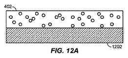
透明散乱板層402(図4)は、入力認識デバイス200(図2)のディスプレイ250のディスプレイスタック内の多数の場所に配置できることは理解されよう。透明散乱板層および表示層に加えて、ディスプレイスタックは、当該技術分野においてよく知られている数多くの他の層を含むことができる。透明散乱板層402(図4)の種々の配置の結果として、アクティブ光源デバイス100(図1)によって透明散乱板層402に向かって放射されるIR光が、複数の光検出器404(図4)に向かっていかに変向するかの特徴が異なる場合がある。たとえば、図12Aは、本発明の一実施形態による、入力認識デバイス200(図2)のディスプレイ250の表示層1202の上方に位置する透明散乱板層402を示す。別の例では、図12Bは、本発明の一実施形態による、入力認識デバイス200(図2)のディスプレイ250の2つの表示層1202間に位置する透明散乱板層402を示す。さらに別の例では、図12Cは、本発明の一実施形態による、入力認識デバイス200(図2)のディスプレイ250の表示層1202の下方に位置する透明散乱板層402を示す。
Transparent Scattering Plate Positioning It will be appreciated that the transparent scattering plate layer 402 (FIG. 4) can be disposed at multiple locations within the display stack of the
透明散乱板層構成要素
透明散乱板層402(図4)は、アクティブ光源デバイス100によって放射されたIR光408を拡散させるように動作可能な種々の液体またはフィルム材料を含むことができる。図13Aは、本発明の一実施形態による、導光層1310と、拡散性感圧接着層1320と、プラスチックフィルム1330とを含む、透明散乱板層を示す。液体またはフィルムに基づく拡散性材料は、アクティブ光源デバイス100によって放射されるIR光408を複数の光検出器404に向かって変向させるか、または拡散させるように動作可能である散乱粒子を含むことができる。そのような拡散性材料の一例が、図13Aに示される透明散乱板層内に埋め込まれる感圧接着層1320である。感圧接着層1320を用いて、フィルムを別のフィルムまたはガラスに積層することができる。これが、拡散性感圧接着層1320を介して導光層1310に積層されるプラスチックフィルム1330に関して示される。図13Aの実施形態において、拡散性感圧接着層1320は、アクティブ光源デバイス100によって導光層1310内に放射されるIR光408を複数の光検出器404に向かって変向させるか、または拡散させるように動作可能な散乱粒子を含むことは理解されよう。
Transparent Scattering Plate Layer Components The transparent scattering plate layer 402 (FIG. 4) can include various liquid or film materials operable to diffuse the IR light 408 emitted by the active
別の例では、図13Bは、本発明の一実施形態による、導光層1310と、透明接着層1340と、拡散フィルム層1350とを含む、透明散乱板層を示す。拡散フィルム1350は、透明接着層1340を介して、導光層1310に積層される。図13Bは、図13Aの場合のように、拡散性感圧接着層1320ではなく、拡散フィルム1350が散乱粒子を含むことを除いて、図13Aと同様である。すなわち、拡散フィルム層1350は、アクティブ光源デバイス100によって導光層1310内に放射されたIR光408を複数の光検出器404に向かって変向させるか、または拡散させるように動作可能な散乱粒子を含む。
In another example, FIG. 13B shows a transparent scattering plate layer including a
複数の光検出器において変向後のIR光408を受光すると、上記の方法に従って、透明散乱板層に対するアクティブ光源デバイス100の位置の特定を行うことができる。
When the converted
光学に基づくアクティブスタイラス入力認識のための方法
図14は、光学に基づくアクティブスタイラス入力認識のための方法の流れ図1400である。ブロック1410において、ユーザが扱うことができるアクティブ光源から、電磁波信号が、平面層に向かって初期方向に放射される。いくつかの実施形態では、アクティブ光源は、アクティブスタイラスデバイスであり、電磁波信号は赤外光を含む。平面層は、入力認識デバイスのディスプレイのディスプレイスタック内の透明散乱板層とすることができる。いくつかの実施形態では、平面層はディスプレイデバイス内の複数の層のうちの1つである。
Method for Active Stylus Input Recognition Based on Optics FIG. 14 is a
ブロック1420において、電磁波信号は、平面層に対して周囲の場所に位置決めされる複数の検出器に向かって、初期方向とは異なる1つまたは複数の横方向に変向する。いくつかの実施形態では、複数の検出器は、変向後の電磁波信号の強度測定値を特定するように動作可能な複数の光検出器を含む。電磁波信号は、光を変向させるように動作可能な複数の散乱体要素を含む透明散乱板層によって横方向に変向することができる。
At
ブロック1430において、変向後の電磁波信号は複数の検出において受信される。入力認識デバイス内の光測定モジュールは、電磁波信号が複数の検出器において受信されたことを検出するように構成することができる。
At
ブロック1440において、複数の検出器において受信される変向後の電磁波信号に基づいて、ユーザ制御光源の位置が推定される。いくつかの実施形態では、推定するステップは、平面層に対するスタイラスデバイスの位置を特定することを含み、位置は強度測定値の関数である。
At
開示されたプロセスにおけるステップの具体的な順序または階層は、代表的な手法の例示であることは理解されたい。設計上の選好に基づいて、プロセスにおけるステップの具体的な順序または階層は再構成される場合があることは理解されたい。さらに、いくつかのステップは、組み合わせられるか、または省略される場合がある。添付の方法クレームは、種々のステップの要素を例示的な順序において提示したものであり、提示された具体的な順序または階層に限定されることは意図していない。 It is to be understood that the specific order or hierarchy of steps in the processes disclosed is an illustration of exemplary approaches. It should be understood that the specific order or hierarchy of steps in the process may be rearranged based on design preferences. Furthermore, some steps may be combined or omitted. The accompanying method claims present elements of the various steps in a sample order, and are not intended to be limited to the specific order or hierarchy presented.
上記の説明は、本明細書において説明される種々の態様を当業者が実践できるようにするために提供される。これらの態様に対する種々の変更形態は、当業者に容易に明らかになり、本明細書において規定される一般原理は、他の態様に適用することができる。さらに、本明細書において開示されるものはいずれも、公共用に提供することは意図していない。 The previous description is provided to enable any person skilled in the art to practice the various aspects described herein. Various modifications to these aspects will be readily apparent to those skilled in the art, and the general principles defined herein may be applied to other aspects. Furthermore, nothing disclosed herein is intended to be provided for public use.
例示的なコンピューティングシステム
図15は、1つまたは複数の実施形態を実施することができるコンピューティングシステムの一例を示す。図15に示されるコンピュータシステムは、上記の入力認識デバイスの一部として組み込まれる場合がある。たとえば、コンピュータシステム1500は、テレビ、コンピューティングデバイス、サーバ、デスクトップ、ワークステーション、自動車内の制御システムまたはインタラクションシステム、タブレット、ネットブック、または任意の他の適切なコンピューティングシステムの構成要素のうちのいくつかを表すことができる。コンピューティングデバイスは、画像キャプチャデバイスまたは入力感知ユニットおよびユーザ出力デバイスを備える任意のコンピューティングデバイスとすることができる。画像キャプチャデバイスまたは入力感知ユニットは、カメラデバイスとすることができる。ユーザ出力デバイスは、ディスプレイユニットとすることができる。コンピューティングデバイスの例は、限定はしないが、ビデオゲーム機、タブレット、スマートフォン、および任意の他のハンドヘルドデバイスを含む。図15は、本明細書において説明されるような、種々の他の実施形態によって提供される方法を実行することができ、および/またはホストコンピュータシステム、リモートキオスク/端末、販売時点情報管理デバイス、自動車内の電話インターフェースもしくはナビゲーションインターフェースもしくはマルチメディアインターフェース、コンピューティングデバイス、セットトップボックス、テーブルコンピュータ、および/またはコンピュータシステムとしての機能を果たすことができる、コンピュータシステム1500の一実施形態の概略図を提供する。図15は、種々の構成要素の一般化された図を提供することのみを意図しており、必要に応じて、そのいずれか、またはすべてが利用される場合がある。したがって、図15は、個々のシステム要素をいかにして、比較的別々に実現できるか、または比較的統合されるように実現できるかを広く示している。いくつかの実施形態では、コンピュータシステム1500は、図2の入力認識デバイスの機能を実施するために用いられる場合がある。
Exemplary Computing System FIG. 15 shows an example of a computing system that can implement one or more embodiments. The computer system shown in FIG. 15 may be incorporated as part of the input recognition device described above. For example,
バス1502を介して電気的に結合することができる(または、適切に他の方法で通信することができる)ハードウェア要素を備えるコンピュータシステム1500が示される。ハードウェア要素は、1つもしくは複数の汎用プロセッサおよび/または1つもしくは複数の専用プロセッサ(デジタル信号処理チップ、グラフィックス高速化プロセッサなど)を限定なしに含む1つまたは複数のプロセッサ1504と、1つまたは複数のカメラ、センサ、マウス、キーボード、超音波または他の音波などを検出するように構成されたマイクロフォンなどを限定なしに含むことができる1つまたは複数の入力デバイス1508と、本発明の実施形態に使用されるデバイスなどのディスプレイユニット、プリンタなどを限定なしに含むことができる1つまたは複数の出力デバイス1510とを含むことができる。
A
本発明の実施形態のいくつかの実施態様では、種々の入力デバイス1508および出力デバイス1510は、ディスプレイデバイス、テーブル、床、壁、およびウィンドウスクリーンなどのインターフェースに埋め込むことができる。さらに、プロセッサに結合された入力デバイス1508および出力デバイス1510は、多次元追跡システムを形成することができる。
In some implementations of embodiments of the present invention,
コンピュータシステム1500は、1つまたは複数の非一時的記憶デバイス1506をさらに含む(および/またはそれらと通信する)ことができ、非一時的記憶デバイスは、限定はしないが、ローカルおよび/もしくはネットワークアクセス可能な記憶装置を備えることができ、ならびに/または、限定はしないが、プログラム可能、フラッシュ更新可能などとすることができる、ディスクドライブ、ドライブアレイ、光記憶デバイス、ランダムアクセスメモリ(「RAM」)および/もしくは読取り専用メモリ(「ROM」)などの固体記憶デバイスを含むことができる。そのような記憶デバイスは、限定はしないが、種々のファイルシステム、データベース構造などを含む、任意の適切なデータ記憶装置を実現するように構成することができる。
コンピュータシステム1500は通信サブシステム1512を備えることもでき、通信サブシステムは、限定はしないが、モデム、ネットワークカード(ワイヤレスもしくは有線)、赤外線通信デバイス、ワイヤレス通信デバイスおよび/またはチップセット(Bluetooth(登録商標)デバイス、802.11デバイス、WiFiデバイス、WiMaxデバイス、セルラー通信設備など)、および/または同様のものを含むことができる。通信サブシステム1512は、ネットワーク、他のコンピュータシステム、および/または本明細書において説明される任意の他のデバイスとデータを交換できるようにする場合がある。多くの実施形態では、コンピュータシステム1500は、上記のような、RAMまたはROMデバイスを含むことができる非一時的ワーキングメモリ1518をさらに備えることになる。
また、コンピュータシステム1500は、オペレーティングシステム1514、デバイスドライバ、実行可能ライブラリ、および/または1つもしくは複数のアプリケーションプログラム1516などの他のコードを含む、現在、ワーキングメモリ1518内に位置するように示されている、ソフトウェア要素も備えることができ、他のコードは、種々の実施形態によって提供されるコンピュータプログラムを備えることができ、かつ/または本明細書において説明されるように、他の実施形態によって提供される方法を実施するように、および/もしくはシステムを構成するように設計することができる。例にすぎないが、先に論じられた方法に関連して説明される1つまたは複数の手順は、コンピュータ(および/またはコンピュータ内のプロセッサ)によって実行可能なコードおよび/または命令として実現することができ、一態様では、その後、そのようなコードおよび/または命令は、説明された方法に従って1つまたは複数の動作を実行するために、汎用コンピュータ(または他のデバイス)を構成するおよび/または適合させるために使用することができる。
Also,
これらの命令および/またはコードのセットは、先に説明された記憶デバイス1506などのコンピュータ可読記憶媒体上に記憶することができる。場合によっては、記憶媒体は、コンピュータシステム1500などのコンピュータシステム内に組み込まれる場合がある。他の実施形態では、記憶媒体は、そこに記憶された命令/コードを用いて汎用コンピュータをプログラムし、構成し、および/または適応させるために使用できるように、コンピュータシステムから分離することができ(たとえば、コンパクトディスクなどのリムーバブル媒体)、かつ/またはインストールパッケージにおいて提供することができる。これらの命令は、コンピュータシステム1500によって実行可能な実行可能コードの形をとることができ、ならびに/または、ソースおよび/もしくはインストール可能コードの形をとることができ、その際、ソースおよび/もしくはインストール可能コードは、(たとえば、様々な一般的に利用可能なコンパイラ、インストールプログラム、圧縮/解凍ユーティリティ、などのいずれかを使用する)コンピュータシステム1500上でのコンパイルおよび/またはインストール時に、実行可能コードの形をとる。
These instructions and / or sets of code may be stored on a computer readable storage medium such as
具体的な要件に従って大幅な変形を行うことができる。たとえば、カスタマイズされたハードウェアが使用される場合もあり、かつ/または、特定の要素が、ハードウェア、ソフトウェア(アプレットなどのようなポータブルソフトウェアを含む)、またはその両方で実現される場合がある。さらに、ネットワーク入力/出力デバイスなどの他のコンピューティングデバイスへの接続が利用される場合もある。いくつかの実施形態では、コンピュータシステム1500の1つまたは複数の要素は、省略することができるか、または図示したシステムとは別に実現することができる。たとえば、プロセッサ1504および/または他の要素は、入力デバイス1508とは別に実現することができる。一実施形態では、プロセッサは、別個に実現される1つまたは複数のカメラから画像を受け取るように構成される。いくつかの実施形態では、図13に示された要素に加えた要素が、コンピュータシステム1500に含まれる場合がある。
Significant modifications can be made according to specific requirements. For example, customized hardware may be used, and / or particular elements may be implemented in hardware, software (including portable software such as applets, etc.), or both. . In addition, connections to other computing devices such as network input / output devices may be utilized. In some embodiments, one or more elements of
いくつかの実施形態は、本開示による方法を実行するために、(コンピュータシステム1500などの)コンピュータシステムを用いることができる。たとえば、説明された方法の手順のうちのいくつかまたはすべては、ワーキングメモリ1518に含まれる(オペレーティングシステム1514および/またはアプリケーションプログラム1516などの他のコードに組み込まれる場合がある)1つまたは複数の命令の1つまたは複数のシーケンスを実行しているプロセッサ1504に応答して、コンピュータシステム1500によって実行される場合がある。そのような命令は、記憶デバイス1506のうちの1つまたは複数などの、別のコンピュータ可読媒体からワーキングメモリ1518に読み込まれる場合がある。例にすぎないが、ワーキングメモリ1518内に含まれる命令のシーケンスの実行は、プロセッサ1504に、本明細書において説明される方法の1つまたは複数の手順を実行させることができる。
Some embodiments can use a computer system (such as computer system 1500) to perform methods in accordance with the present disclosure. For example, some or all of the described method steps may be included in working memory 1518 (which may be incorporated into
本明細書において使用されるときに、「機械可読媒体」および「コンピュータ可読媒体」という用語は、機械を特定の方式で動作させるデータを与えることに関与する任意の媒体を指す。コンピュータシステム1500を使用して実現されるいくつかの実施形態では、種々のコンピュータ可読媒体が、実行のためにプロセッサ1504に命令/コードを与えることに関与することがあり、かつ/またはそのような命令/コードを(たとえば、信号として)記憶および/または搬送するために使用されることがある。数多くの実施態様において、コンピュータ可読媒体は物理的な記憶媒体および/または有形の記憶媒体である。そのような媒体は、限定はしないが、不揮発性媒体、揮発性媒体、および伝送媒体を含む、数多くの形をとることができる。不揮発性媒体は、たとえば、記憶デバイス1506などの光ディスクおよび/または磁気ディスクを含む。揮発性媒体は、限定はしないが、ワーキングメモリ1518などのダイナミックメモリを含む。伝送媒体は、限定はしないが、バス1502、ならびに通信サブシステム1512の種々の構成要素(および/または通信サブシステム1512が他のデバイスとの通信を提供する媒体)を含む電線を含む、同軸ケーブル、銅線、および光ファイバを含む。したがって、伝送媒体はまた、波(限定はしないが、無線波データ通信および赤外線データ通信中に生成されるような電波、音波、および/または光波を含む)の形をとることができる。
As used herein, the terms "machine-readable medium" and "computer-readable medium" refer to any medium that participates in providing data that causes a machine to operate in a specific manner. In some embodiments implemented using
物理的な、かつ/または有形のコンピュータ可読媒体の一般的な形は、たとえば、フロッピーディスク、フレキシブルディスク、ハードディスク、磁気テープ、または任意の他の磁気媒体、CD-ROM、任意の他の光学媒体、パンチカード、紙テープ、穴のパターンを有する任意の他の物理媒体、RAM、PROM、EPROM、フラッシュEPROM、任意の他のメモリチップまたはカートリッジ、以下において説明されるような搬送波、あるいはコンピュータが命令および/またはコードを読み取ることのできる任意の他の媒体を含む。 A common form of physical and / or tangible computer readable medium is, for example, a floppy disk, a flexible disk, a hard disk, a magnetic tape, or any other magnetic medium, a CD-ROM, any other optical medium , Punch card, paper tape, any other physical medium having a pattern of holes, RAM, PROM, EPROM, flash EPROM, any other memory chip or cartridge, carrier wave as described below, or computer instructions and And / or any other medium capable of reading the code.
種々の形のコンピュータ可読媒体が、プロセッサ1504が実行するための1つまたは複数の命令からなる1つまたは複数のシーケンスを搬送する際に関与することができる。例にすぎないが、命令は最初に、リモートコンピュータの磁気ディスクおよび/または光ディスク上で搬送することができる。リモートコンピュータは、命令をそのダイナミックメモリ内にロードすることができ、コンピュータシステム1500によって受信および/または実行されるように、送信媒体を介して信号として命令を送信することができる。電磁信号、音響信号、光信号などの形をとる場合があるこれらの信号はすべて、本発明の種々の実施形態による、命令を符号化できる搬送波の例である。
Various forms of computer readable media may be involved in carrying one or more sequences of one or more instructions to
通信サブシステム1512(および/またはその構成要素)は、一般に信号を受信し、次いで、バス1502は、信号(および/または、信号によって搬送されるデータ、命令など)を作業メモリ1518に搬送することができ、プロセッサ1504は、作業メモリ1518から命令を取り出し、実行する。ワーキングメモリ1518によって受信された命令は、オプションで、プロセッサ1504による実行の前または後のいずれかに、非一時的記憶デバイス1506上に記憶することができる。
Communication subsystem 1512 (and / or its components) generally receives the signals, and then
先に論じられた方法、システム、およびデバイスは例である。種々の実施形態は、必要に応じて、種々の手順または構成要素を省略、置換、または追加することができる。たとえば、代替の構成では、説明される方法は、説明される順序とは異なる順序で実施される場合があり、かつ/または、種々のステージの追加、省略、および/もしくは組合せが行われる場合がある。さらに、特定の実施形態に関して説明された特徴は、種々の他の実施形態において組み合わせることができる。実施形態の異なる態様および要素は、同じように組み合わせることができる。また、技術は発展するので、要素のうちの多くは、本開示の範囲をそれらの具体例に限定しない例である。 The methods, systems, and devices discussed above are examples. Various embodiments may omit, substitute, or add various procedures or components as desired. For example, in alternative configurations, the methods described may be performed in an order different from that described and / or various additions, omissions, and / or combinations of stages may occur. is there. Furthermore, the features described with respect to particular embodiments can be combined in various other embodiments. The different aspects and elements of the embodiments can be combined in the same way. Also, as technology evolves, many of the elements are examples that do not limit the scope of the present disclosure to those specific examples.
実施形態を十分に理解してもらうために、説明において具体的な詳細が与えられている。しかしながら、実施形態は、これらの具体的な詳細を伴わずに実践することができる。たとえば、実施形態を不明瞭することを避けるために、周知の回路、プロセス、アルゴリズム、構造、および技法は、無用に詳述することなく示されている。この説明は例示的な実施形態のみに関する説明であり、本発明の範囲、適用性、または構成を限定することは意図していない。むしろ、実施形態のこれらの説明は、本発明の実施形態を実施することを可能にする説明を当業者に与える。本発明の趣旨および範囲から逸脱することなく、要素の機能および構成に種々の変更を加えることができる。 Specific details are given in the description to provide a thorough understanding of the embodiments. However, embodiments may be practiced without these specific details. For example, well-known circuits, processes, algorithms, structures, and techniques are shown without undue detailing in order to avoid obscuring the embodiments. This description is of an exemplary embodiment only, and is not intended to limit the scope, applicability, or configuration of the present invention. Rather, these descriptions of the embodiments provide those skilled in the art with a description that enables one to practice the embodiments of the present invention. Various changes can be made in the function and arrangement of elements without departing from the spirit and scope of the present invention.
また、いくつかの実施形態は、流れ図またはブロック図として図示されているプロセスとして説明される。各々は動作を順次のプロセスとして説明するが、動作の多くは、並列に、または同時に実行することができる。さらに、動作の順序は、並べ替えられることができる。プロセスは、図に含まれないさらなるステップを有する場合もある。さらに、方法の実施形態は、ハードウェア、ソフトウェア、ファームウェア、ミドルウェア、マイクロコード、ハードウェア記述言語、またはこれらの任意の組合せによって実現することができる。ソフトウェア、ファームウェア、ミドルウェア、またはマイクロコードにおいて実現されるときに、関連するタスクを実行するためのプログラムコードまたはコードセグメントは、記憶媒体などのコンピュータ可読媒体に記憶することができる。プロセッサは、関連するタスクを実行することができる。したがって、上記の説明では、コンピュータシステムによって実行されるものとして記述された機能または方法は、プロセッサ、たとえば、機能または方法を実行するように構成されたプロセッサ1504によって実行することができる。さらに、そのような機能または方法は、1つまたは複数のコンピュータ可読媒体に記憶されたプロセッサ実行命令によって実行することができる。
Also, some embodiments are described as processes illustrated as flow diagrams or block diagrams. Although each describes the operations as a sequential process, many of the operations can be performed in parallel or simultaneously. Furthermore, the order of operations can be rearranged. The process may have additional steps not included in the figure. Furthermore, the embodiments of the method can be realized by hardware, software, firmware, middleware, microcode, hardware description language, or any combination thereof. When implemented in software, firmware, middleware or microcode, program code or code segments for performing the associated tasks may be stored on a computer readable medium, such as a storage medium. A processor can perform the associated task. Thus, in the above description, a function or method described as being performed by a computer system may be performed by a processor, eg,
いくつかの実施形態を説明してきたが、種々の変更、代替構造、および均等物が本開示の趣旨から逸脱することなく使用される場合がある。たとえば、上記の要素は、単により大きいシステムの構成要素とすることができ、他のルールが、本発明の適用例よりも優先するか、そうでなければ本発明の適用例を変更することができる。また、上記の要素が考慮される前、その間に、またはその後に、いくつかのステップを行うことができる。したがって、上記の説明は本開示の範囲を限定しない。 Although several embodiments have been described, various modifications, alternative constructions, and equivalents may be used without departing from the spirit of the present disclosure. For example, the above elements may simply be components of a larger system, and other rules may supersede or otherwise modify the application of the invention. it can. Also, several steps can be taken before, during, or after the above factors are considered. Thus, the above description does not limit the scope of the present disclosure.
種々の例が説明されてきた。これらの例および他の例は以下の特許請求の範囲内に入る。 Various examples have been described. These and other examples are within the scope of the following claims.
100 アクティブ光源デバイス
110 プロセッサ
120 発光ダイオード(LED)
150 メモリ
160 ジャイロスコープ
180 加速度計
200 入力認識デバイス
210 プロセッサ
222 第1の光検出器
224 第2の光検出器
226 第3の光検出器
228 第4の光検出器
230 メモリ
232 第1のモジュール
234 第2のモジュール
240 コンピュータ可読媒体
242 光測定モジュール
250 ディスプレイ
402 透明散乱板層
404 光検出器
408 IR光
410 散乱体
610 グラフ
620 表
710 円錐ファセット
810 ファセット
1004 光検出器
1104 光検出器
1202 表示層
1310 導光層
1320 拡散性感圧接着層
1330 プラスチックフィルム
1340 透明接着層
1350 拡散フィルム層
1500 コンピュータシステム
1502 バス
1504 1つまたは複数のプロセッサ
1506 記憶デバイス
1508 入力デバイス
1510 出力デバイス
1512 通信サブシステム
1514 オペレーティングシステム
1516 アプリケーションプログラム
1518 ワーキングメモリ
100 Active Light Source Device
110 processor
120 light emitting diode (LED)
150 memory
160 gyroscope
180 accelerometer
200 input recognition device
210 processor
222 First light detector
224 Second light detector
226 Third Detector
228 Fourth light detector
230 memory
232 First Module
234 Second Module
240 computer readable media
242 Light Measurement Module
250 display
402 Transparent scattering plate layer
404 light detector
408 IR light
410 Scatterer
610 graph
620 Table
710 conical facets
810 facets
1004 light detector
1104 light detector
1202 Display Layer
1310 Light guiding layer
1320 Diffusion pressure sensitive adhesive layer
1330 Plastic film
1340 Transparent adhesive layer
1350 Diffusion film layer
1500 computer systems
1502 bus
1504 One or more processors
1506 storage device
1508 input device
1510 output device
1512 Communication subsystem
1514 operating system
1516 Application program
1518 Working Memory
Claims (13)
前記平面層に対して周囲の場所に位置決めされる複数の検出器に向かって、前記電磁波信号を前記初期方向とは異なる前記平面層内の1つまたは複数の横方向に変向させるステップと、
前記複数の検出器において、前記変向後の電磁波信号を受信するステップと、
前記複数の検出器のそれぞれにおいて受信された前記変向後の電磁波信号の複数の強度測定値に基づいて、前記アクティブ光源の位置を推定するステップであって、前記アクティブ光源の位置が、前記平面層に対する前記アクティブ光源の位置、および前記高さを含む、ステップとを含む、方法。 Emitting an electromagnetic wave signal in an initial direction towards the planar layer from an active light source that can be handled by the user, the active light source being located at a height above the planar layer, the planar layer being Including a scattering plate layer comprising an array of conical facets that redirect light emitted from the active light source towards a scattering plate layer;
Deflecting the electromagnetic wave signal in one or more lateral directions in the planar layer different from the initial direction towards a plurality of detectors positioned at peripheral locations relative to the planar layer;
Receiving the transformed electromagnetic wave signal at the plurality of detectors;
Estimating the position of the active light source based on a plurality of intensity measurements of the transformed electromagnetic wave signal received at each of the plurality of detectors, the position of the active light source being the planar layer And the step of including the position of the active light source with respect to and the height .
前記平面層に対して周囲の場所に位置決めされる複数の検出器に向かって、前記電磁波信号を前記初期方向とは異なる前記平面層内の1つまたは複数の横方向に変向させるための手段と、
前記複数の検出器において、前記変向後の電磁波信号を受信するための手段と、
前記複数の検出器のそれぞれにおいて受信された前記変向後の電磁波信号の複数の強度測定値に基づいて、前記アクティブ光源の位置を推定するための手段であって、前記アクティブ光源の位置が、前記平面層に対する前記アクティブ光源の位置、および前記高さを含む、手段とを備える、装置。 Means for emitting an electromagnetic wave signal in an initial direction towards the planar layer from an active light source which can be handled by the user, the active light source being located at a height above the planar layer, the planar layer is the scattering plate layer including comprising an array of conical facets for deflecting the light emitted from said active light source toward the scattering plate layer, and means,
Means for deflecting the electromagnetic wave signal laterally in one or more of the planar layers different from the initial direction towards a plurality of detectors positioned at peripheral locations relative to the planar layer When,
Means for receiving the transformed electromagnetic wave signal in the plurality of detectors;
Means for estimating the position of the active light source based on a plurality of intensity measurements of the transformed electromagnetic wave signal received at each of the plurality of detectors, the position of the active light source being the Means comprising the position of the active light source relative to the planar layer, and the height .
Applications Claiming Priority (3)
| Application Number | Priority Date | Filing Date | Title |
|---|---|---|---|
| US14/204,989 US9298284B2 (en) | 2014-03-11 | 2014-03-11 | System and method for optically-based active stylus input recognition |
| US14/204,989 | 2014-03-11 | ||
| PCT/US2015/018253 WO2015138173A1 (en) | 2014-03-11 | 2015-03-02 | System and method for optically-based active stylus input recognition |
Publications (3)
| Publication Number | Publication Date |
|---|---|
| JP2017508217A JP2017508217A (en) | 2017-03-23 |
| JP2017508217A5 JP2017508217A5 (en) | 2018-03-29 |
| JP6511469B2 true JP6511469B2 (en) | 2019-05-15 |
Family
ID=52727393
Family Applications (1)
| Application Number | Title | Priority Date | Filing Date |
|---|---|---|---|
| JP2016555969A Active JP6511469B2 (en) | 2014-03-11 | 2015-03-02 | System and method for active stylus input recognition based on optics |
Country Status (7)
| Country | Link |
|---|---|
| US (1) | US9298284B2 (en) |
| EP (1) | EP3117294B1 (en) |
| JP (1) | JP6511469B2 (en) |
| KR (1) | KR102254580B1 (en) |
| CN (1) | CN106062687B (en) |
| BR (1) | BR112016020906A8 (en) |
| WO (1) | WO2015138173A1 (en) |
Families Citing this family (15)
| Publication number | Priority date | Publication date | Assignee | Title |
|---|---|---|---|---|
| EP3250993B1 (en) | 2015-01-28 | 2019-09-04 | FlatFrog Laboratories AB | Dynamic touch quarantine frames |
| WO2016130074A1 (en) | 2015-02-09 | 2016-08-18 | Flatfrog Laboratories Ab | Optical touch system comprising means for projecting and detecting light beams above and inside a transmissive panel |
| EP4075246A1 (en) | 2015-12-09 | 2022-10-19 | FlatFrog Laboratories AB | Stylus for optical touch system |
| HUE059960T2 (en) | 2016-12-07 | 2023-01-28 | Flatfrog Lab Ab | A curved touch device |
| EP3458946B1 (en) | 2017-02-06 | 2020-10-21 | FlatFrog Laboratories AB | Optical coupling in touch-sensing systems |
| WO2018174788A1 (en) | 2017-03-22 | 2018-09-27 | Flatfrog Laboratories | Object characterisation for touch displays |
| EP3602259A4 (en) | 2017-03-28 | 2021-01-20 | FlatFrog Laboratories AB | Touch sensing apparatus and method for assembly |
| CN117311543A (en) | 2017-09-01 | 2023-12-29 | 平蛙实验室股份公司 | Touch sensing device |
| US11567610B2 (en) | 2018-03-05 | 2023-01-31 | Flatfrog Laboratories Ab | Detection line broadening |
| JP2019159865A (en) * | 2018-03-14 | 2019-09-19 | 富士通株式会社 | Control program, control method, and information processing apparatus |
| JP7308188B2 (en) * | 2018-05-14 | 2023-07-13 | 株式会社ワコム | learning support system |
| US11943563B2 (en) | 2019-01-25 | 2024-03-26 | FlatFrog Laboratories, AB | Videoconferencing terminal and method of operating the same |
| US11886650B2 (en) * | 2019-04-19 | 2024-01-30 | Apple Inc. | Stylus-based input system for a head-mounted device |
| EP4104042A1 (en) | 2020-02-10 | 2022-12-21 | FlatFrog Laboratories AB | Improved touch-sensing apparatus |
| KR102446916B1 (en) * | 2022-06-03 | 2022-09-23 | 주식회사 보나 | optical digital pen by use of light scattering having fusion-spliced optical fiber |
Family Cites Families (26)
| Publication number | Priority date | Publication date | Assignee | Title |
|---|---|---|---|---|
| JPS5488734A (en) * | 1977-12-26 | 1979-07-14 | Nippon Telegr & Teleph Corp <Ntt> | Data tablet |
| JPS5539955A (en) * | 1978-09-14 | 1980-03-21 | Nippon Telegr & Teleph Corp <Ntt> | Coordinate input device |
| US4150285A (en) | 1977-12-27 | 1979-04-17 | United Technologies Corporation | Remote optical display designator |
| JPH05119909A (en) * | 1991-10-25 | 1993-05-18 | Fujitsu Ltd | Optical coordinate input device |
| GB2299856B (en) | 1995-04-13 | 1999-03-24 | Motorola Israel Ltd | Position-determining input device |
| JPH11327769A (en) * | 1998-05-08 | 1999-11-30 | Nec Corp | Coordinate input device |
| DE60307077T2 (en) | 2002-03-13 | 2007-03-01 | O-Pen Aps | TOUCH PAD AND METHOD FOR OPERATING THE TOUCH PAD |
| US7442914B2 (en) * | 2003-09-12 | 2008-10-28 | Flatfrog Laboratories Ab | System and method of determining a position of a radiation emitting element |
| US8094136B2 (en) | 2006-07-06 | 2012-01-10 | Flatfrog Laboratories Ab | Optical touchpad with three-dimensional position determination |
| US20080029316A1 (en) * | 2006-08-07 | 2008-02-07 | Denny Jaeger | Method for detecting position of input devices on a screen using infrared light emission |
| WO2008018768A1 (en) * | 2006-08-10 | 2008-02-14 | Lg Chem, Ltd. | A light guide plate for system inputting coordinate contactlessly, a system comprising the same and a method for inputting coordinate contactlessly using the same |
| KR20090030030A (en) * | 2007-09-19 | 2009-03-24 | 삼성전자주식회사 | Touch screen |
| CN101398720B (en) * | 2007-09-30 | 2010-11-03 | 联想(北京)有限公司 | Pen interactive device |
| US20090126792A1 (en) * | 2007-11-16 | 2009-05-21 | Qualcomm Incorporated | Thin film solar concentrator/collector |
| JP5500601B2 (en) * | 2008-07-15 | 2014-05-21 | イシキリ インターフェイス テクノロジーズ ゲーエムベーハー | Control panel for data processor |
| KR101351168B1 (en) * | 2009-01-07 | 2014-01-14 | 아이시키리 인터페이스 테크놀로지스 게엠베하 | Detector surface |
| ES2569120T3 (en) | 2009-01-14 | 2016-05-06 | Perceptive Pixel, Inc. | Touch sensitive display device |
| AU2010236331B2 (en) * | 2009-04-16 | 2013-10-03 | Neonode Inc. | Optical touch screen systems using reflected light |
| AT508439B1 (en) * | 2009-04-21 | 2011-12-15 | Isiqiri Interface Tech Gmbh | METHOD AND DEVICE FOR CONTROLLING A DATA PROCESSING SYSTEM |
| JP5381833B2 (en) | 2009-07-31 | 2014-01-08 | セイコーエプソン株式会社 | Optical position detection device and display device with position detection function |
| EP2488931A4 (en) | 2009-10-16 | 2013-05-29 | Rpo Pty Ltd | Methods for detecting and tracking touch objects |
| US8436833B2 (en) | 2009-11-25 | 2013-05-07 | Corning Incorporated | Methods and apparatus for sensing touch events on a display |
| TWI421753B (en) * | 2010-08-12 | 2014-01-01 | Lite On Semiconductor Corp | Calibration method, detection device and optical touch panel for optical touch panel |
| CN102541356A (en) * | 2010-12-24 | 2012-07-04 | 敦南科技股份有限公司 | Touch point positioning method for optical touch panel and optical touch panel device |
| TWI438669B (en) * | 2011-04-14 | 2014-05-21 | Wistron Corp | Optical touch module and method thereof |
| JP2013089114A (en) * | 2011-10-20 | 2013-05-13 | Ihi Corp | Three-dimensional input device |
-
2014
- 2014-03-11 US US14/204,989 patent/US9298284B2/en active Active
-
2015
- 2015-03-02 CN CN201580011629.9A patent/CN106062687B/en active Active
- 2015-03-02 EP EP15711937.1A patent/EP3117294B1/en not_active Not-in-force
- 2015-03-02 JP JP2016555969A patent/JP6511469B2/en active Active
- 2015-03-02 BR BR112016020906A patent/BR112016020906A8/en active Search and Examination
- 2015-03-02 WO PCT/US2015/018253 patent/WO2015138173A1/en active Application Filing
- 2015-03-02 KR KR1020167024517A patent/KR102254580B1/en active IP Right Grant
Also Published As
| Publication number | Publication date |
|---|---|
| US20150261323A1 (en) | 2015-09-17 |
| JP2017508217A (en) | 2017-03-23 |
| EP3117294A1 (en) | 2017-01-18 |
| KR20160130387A (en) | 2016-11-11 |
| US9298284B2 (en) | 2016-03-29 |
| WO2015138173A1 (en) | 2015-09-17 |
| CN106062687B (en) | 2018-12-18 |
| BR112016020906A2 (en) | 2017-08-15 |
| CN106062687A (en) | 2016-10-26 |
| BR112016020906A8 (en) | 2021-06-15 |
| KR102254580B1 (en) | 2021-05-20 |
| EP3117294B1 (en) | 2018-07-25 |
Similar Documents
| Publication | Publication Date | Title |
|---|---|---|
| JP6511469B2 (en) | System and method for active stylus input recognition based on optics | |
| CN107526953B (en) | Electronic device supporting fingerprint authentication function and operation method thereof | |
| US10324566B2 (en) | Enhanced interaction touch system | |
| KR101796660B1 (en) | Electronic device for supporting the fingerprint verification and operating method thereof | |
| CN107408045B (en) | Method of controlling apparatus having a plurality of operating systems installed therein and the apparatus | |
| EP3451661A1 (en) | Three-dimensional imaging device and electronic device including same | |
| KR102534186B1 (en) | Electronic Device which includes Fingerprint Sensor | |
| US20150242038A1 (en) | Filter module to direct audio feedback to a plurality of touch monitors | |
| US20120113044A1 (en) | Multi-Sensor Device | |
| KR20180005833A (en) | Electronic device including integrated sensor and operating method thereof | |
| CN113010055A (en) | Method and apparatus for facilitating user interaction with a foldable display | |
| KR20150024530A (en) | Electronic device for sensing proximity touch and controlling method thereof | |
| JP2015512106A (en) | Detection of user input at the edge of the display area | |
| WO2014018119A1 (en) | Ultrasound-based force and touch sensing | |
| US20160226547A1 (en) | Case for Electronic Device, Electronic Device Using the Same, and Notification Method Thereof | |
| EP2808774A2 (en) | Electronic device for executing application in response to user input | |
| EP2634673A1 (en) | Remote control and remote control program | |
| US20140282228A1 (en) | Dynamically Enable, Variable Border Area for Touch Solution with a Bezel | |
| KR102502889B1 (en) | Electronic device for providing time information and a method for the same | |
| KR20150002160A (en) | electronic apparatus and touch sensing method using the smae | |
| US9875019B2 (en) | Indicating a transition from gesture based inputs to touch surfaces | |
| US10275092B2 (en) | Transforming received touch input | |
| KR102649194B1 (en) | Cross-talk prevention structure of electronic device for measuring distance to external object | |
| CN107111354B (en) | Unintended touch rejection | |
| US20160266770A1 (en) | Multi-selector contextual action paths |
Legal Events
| Date | Code | Title | Description |
|---|---|---|---|
| A521 | Request for written amendment filed |
Free format text: JAPANESE INTERMEDIATE CODE: A523 Effective date: 20160913 |
|
| A521 | Request for written amendment filed |
Free format text: JAPANESE INTERMEDIATE CODE: A523 Effective date: 20180215 |
|
| A621 | Written request for application examination |
Free format text: JAPANESE INTERMEDIATE CODE: A621 Effective date: 20180215 |
|
| A131 | Notification of reasons for refusal |
Free format text: JAPANESE INTERMEDIATE CODE: A131 Effective date: 20181029 |
|
| A977 | Report on retrieval |
Free format text: JAPANESE INTERMEDIATE CODE: A971007 Effective date: 20181024 |
|
| A521 | Request for written amendment filed |
Free format text: JAPANESE INTERMEDIATE CODE: A523 Effective date: 20181227 |
|
| TRDD | Decision of grant or rejection written | ||
| A01 | Written decision to grant a patent or to grant a registration (utility model) |
Free format text: JAPANESE INTERMEDIATE CODE: A01 Effective date: 20190311 |
|
| A61 | First payment of annual fees (during grant procedure) |
Free format text: JAPANESE INTERMEDIATE CODE: A61 Effective date: 20190408 |
|
| R150 | Certificate of patent or registration of utility model |
Ref document number: 6511469 Country of ref document: JP Free format text: JAPANESE INTERMEDIATE CODE: R150 |
|
| R250 | Receipt of annual fees |
Free format text: JAPANESE INTERMEDIATE CODE: R250 |
|
| R250 | Receipt of annual fees |
Free format text: JAPANESE INTERMEDIATE CODE: R250 |