JP6510059B2 - Starting method of loom - Google Patents
Starting method of loom Download PDFInfo
- Publication number
- JP6510059B2 JP6510059B2 JP2017542027A JP2017542027A JP6510059B2 JP 6510059 B2 JP6510059 B2 JP 6510059B2 JP 2017542027 A JP2017542027 A JP 2017542027A JP 2017542027 A JP2017542027 A JP 2017542027A JP 6510059 B2 JP6510059 B2 JP 6510059B2
- Authority
- JP
- Japan
- Prior art keywords
- opening device
- time
- loom
- rotational speed
- overspeed
- Prior art date
- Legal status (The legal status is an assumption and is not a legal conclusion. Google has not performed a legal analysis and makes no representation as to the accuracy of the status listed.)
- Active
Links
- 238000000034 method Methods 0.000 title claims description 40
- 238000004364 calculation method Methods 0.000 claims description 24
- 230000008569 process Effects 0.000 claims description 24
- 230000005540 biological transmission Effects 0.000 claims description 3
- 230000007423 decrease Effects 0.000 claims description 3
- 230000003247 decreasing effect Effects 0.000 claims description 3
- 238000009941 weaving Methods 0.000 description 31
- 230000000630 rising effect Effects 0.000 description 4
- 238000010586 diagram Methods 0.000 description 3
- 230000009467 reduction Effects 0.000 description 3
- 230000002123 temporal effect Effects 0.000 description 3
- 230000001960 triggered effect Effects 0.000 description 3
- 238000004519 manufacturing process Methods 0.000 description 2
- 239000004753 textile Substances 0.000 description 2
- 238000012546 transfer Methods 0.000 description 2
- 230000007704 transition Effects 0.000 description 2
- 238000012935 Averaging Methods 0.000 description 1
- 230000001133 acceleration Effects 0.000 description 1
- 230000004913 activation Effects 0.000 description 1
- 238000010009 beating Methods 0.000 description 1
- 230000008901 benefit Effects 0.000 description 1
- 239000004020 conductor Substances 0.000 description 1
- 238000012937 correction Methods 0.000 description 1
- 239000004744 fabric Substances 0.000 description 1
- 238000003780 insertion Methods 0.000 description 1
- 230000037431 insertion Effects 0.000 description 1
- 230000010354 integration Effects 0.000 description 1
- 238000012423 maintenance Methods 0.000 description 1
- 238000012986 modification Methods 0.000 description 1
- 230000004048 modification Effects 0.000 description 1
- 238000010079 rubber tapping Methods 0.000 description 1
- 238000010998 test method Methods 0.000 description 1
- 238000012795 verification Methods 0.000 description 1
- 230000003313 weakening effect Effects 0.000 description 1
Images


Classifications
-
- D—TEXTILES; PAPER
- D03—WEAVING
- D03D—WOVEN FABRICS; METHODS OF WEAVING; LOOMS
- D03D51/00—Driving, starting, or stopping arrangements; Automatic stop motions
-
- D—TEXTILES; PAPER
- D03—WEAVING
- D03D—WOVEN FABRICS; METHODS OF WEAVING; LOOMS
- D03D51/00—Driving, starting, or stopping arrangements; Automatic stop motions
- D03D51/002—Avoiding starting marks
-
- D—TEXTILES; PAPER
- D03—WEAVING
- D03D—WOVEN FABRICS; METHODS OF WEAVING; LOOMS
- D03D51/00—Driving, starting, or stopping arrangements; Automatic stop motions
- D03D51/005—Independent drive motors
-
- D—TEXTILES; PAPER
- D03—WEAVING
- D03D—WOVEN FABRICS; METHODS OF WEAVING; LOOMS
- D03D51/00—Driving, starting, or stopping arrangements; Automatic stop motions
- D03D51/007—Loom optimisation
Landscapes
- Engineering & Computer Science (AREA)
- Textile Engineering (AREA)
- Looms (AREA)
Description
本発明は、織機および開口装置の制御された始動すなわち運転のための方法に関し、織機は主駆動装置によって駆動され、開口装置は電気モータ補助駆動装置によって駆動される。 The present invention relates to a method for the controlled starting or operation of a weaving machine and an opening device, the weaving machine being driven by a main drive and the opening device being driven by an electric motor assisted drive.
このような織機および開口装置は公知である。これらにおいて、開口装置は、中心駆動シャフトが電気モータに接続された別個の駆動装置を含み、中心駆動シャフトからは開口手段の運動が誘導される。これに関し、開口手段が中心駆動シャフトの運動から分離されることができる開口装置として、Staeubli社のタイプ2881のドビー機、またはStaeubli社のタイプLXのジャカード機、またはBonas社のSIが挙げられる。 Such weaving machines and opening devices are known. In these, the opening device comprises a separate drive whose central drive shaft is connected to the electric motor, from which the movement of the opening means is induced. In this regard, the opening device can be separated from the movement of the central drive shaft, such as the Staubli type 2881 dobby machine, or the Staeubli type LX jacquard machine, or the Bonas SI .
織機の駆動シャフトは、そこからさらなる運動(織機筬、該当する場合、機械的な緯入れ要素)が誘導されるものであるが、次に、それを直接駆動する少なくとも1つのアクチュエータに接続され、アクチュエータは、同様に通常は電気モータとして実現される。このような直接駆動は、機械的構造が非常に簡単で、ほぼメンテナンスが不要であり、非常に正確に調整可能である。 The drive shaft of the weaving machine, from which further movement (the weaving machine, if applicable mechanical weft insertion element) is induced, is then connected to at least one actuator which drives it directly, The actuator is likewise usually realized as an electric motor. Such direct drive has a very simple mechanical structure, requires almost no maintenance, and can be adjusted very accurately.
さらに、織機の駆動装置および開口装置の駆動装置は、共通のDC電圧中間回路(以後、コンバータ中間回路と呼ぶ)によって接続され、これにより、相互に一緒になってエネルギー流を形成または生成することができる。 Furthermore, the drive of the weaving machine and the drive of the opening device are connected by a common DC voltage intermediate circuit (hereinafter referred to as a converter intermediate circuit), thereby forming or generating an energy flow together. Can.
前述の織機の直接駆動の欠点の1つは、要求される高度に動的な織機の始動に必要な高いピーク電力が、アクチュエータを介して直接供給されなければならないことである。このピーク電力は、本質的に電源ネットワークにより直接供給されるべきである。このような電力ピークは、安定した電源ネットワークおよび適切な電源導体断面の場合でさえ、強い電圧降下をもたらし、このような電圧降下は直接駆動に利用されるコンバータの中間回路電圧にさらに進展し、織機始動の中断および停止を誤ってトリガすることになり得る。織機が弱電源ネットワーク上で動作する場合、この問題は一層顕著になる。開発途上国や新興国への繊維生産のシフトがますます進んでいる。電源ネットワークの定格電圧レベルおよび/またはタイプのために予備変圧器が必要になった場合、その条件はさらに不利になり、それにより、予備変圧器は、追加の特性インピーダンスのために、始動すべき織機の観点から電源ネットワークをさらに弱くする。 One of the disadvantages of the above-described direct drive of the loom is that the high peak power required for the required highly dynamic loom start-up must be supplied directly via the actuator. This peak power should essentially be supplied directly by the power supply network. Such power peaks lead to strong voltage drops even in the case of stable power supply networks and appropriate power supply conductor cross sections, which further develop into the intermediate circuit voltage of the converter used for direct drive, Interruptions and stops of the loom start can be falsely triggered. This problem is even more pronounced if the loom operates on a weak power supply network. The shift in textile production to developing and emerging countries is on the rise. If a reserve transformer is required because of the rated voltage level and / or type of the power supply network, the condition becomes further disadvantageous, whereby the reserve transformer should be started because of the additional characteristic impedance. Further weakening the power supply network from the perspective of the weaving machine.
最初の筬打ちに提供される回転速度(以下、動作回転速度と呼ぶ)までに織機が始動することが上記の理由により可能ではない場合には、この回転速度を低下させる対策が知られている。つまり、最初の筬打ちのための動作回転速度は、物品に実際に提供される動作回転速度と著しく異なる場合がある。しかしながら、これは、織物にスタートマークや許容できない品質の低下を招く可能性がある。同様に、動作回転速度の一般的な低下は許容可能な解決策ではなく、なぜなら、製品の生産がそれに対応してより長くかかるため、製織工場の経済的な収益性に問題があるからである。 If it is not possible for the loom to start up to the rotational speed provided for the first beating (hereinafter referred to as the operating rotational speed) for the above reasons, measures are known to reduce this rotational speed . That is, the operating rotational speed for the first strike may be significantly different than the operating rotational speed actually provided to the article. However, this can cause the fabric to have a start mark and an unacceptable loss of quality. Likewise, a general reduction in the operating speed is not an acceptable solution, because there is a problem with the economic profitability of the weaving mill, as production of the product takes correspondingly longer. .
独国実用新案権第20021049号明細書は、最も近い先行技術として、織機および開口装置用の別々の駆動装置についての実現性を示し、これは、独国特許第10053079号明細書から知られている開口装置の好ましい始動プロセスを構成し、運動エネルギーを有する織機のそれに続く始動プロセスを支援するようになっている。そのために、開口装置は、織機の始動の終わりに到達すべき動作回転速度を超える回転速度まで加速される。その後、織機が始動するまでの間に、すなわち始動段階の間に、開口装置は、織機の始動を支援するために、再制動によって運動エネルギーを放出する。 German Utility Model No. 20021049 shows, as the closest prior art, the possibility for separate drives for looms and opening devices, which is known from DE 100 530 079. The preferred start-up process of the opening device is adapted to support the subsequent start-up process of the loom having kinetic energy. To that end, the opening device is accelerated to a rotational speed which exceeds the operating rotational speed to be reached at the end of the start of the loom. Thereafter, during the start of the loom, i.e. during the start-up phase, the opening device releases kinetic energy by re-braking to assist the start of the loom.
独国実用新案権第20021049号明細書は、とりわけ、織物および開口装置のための一般的な電動要素を有する駆動装置の解決策に焦点が当てられていることにより、開口装置の制動プロセスは、織機始動のはじめに始まり、この始動プロセスの間に(実質的に)均一に進行することが提案されている。しかしながら、織機始動のはじめには、開口装置が織機によって必要とされるよりも多くのエネルギーをフィードバックすることになるため、このようなフィードバックは最適ではないことが判明した。織機および開口装置の駆動装置の共通のコンバータ中間回路の電圧レベルは、その後、急激に上昇し、そのエネルギーは制動抵抗の熱に変換されなければならず、プロセスのために失われることになる。 German Utility Model DE 200 21 049 focuses, inter alia, on the drive solution having a common motorized element for textiles and opening devices, so that the braking process of the opening devices is: It is proposed to start at the beginning of the loom start-up and proceed (substantially) uniformly during this start-up process. However, at the beginning of the loom start-up such feedback has proved to be suboptimal, as the opening device will feedback more energy than required by the loom. The voltage level of the common converter intermediate circuit of the loom and the drive of the opening device then rises sharply and its energy has to be converted into heat of the braking resistor, which will be lost for the process.
したがって、本発明の目的は、開口装置の運動フィードバックエネルギーをより有効に利用することにより、織機のピーク電力要求を低減することであり、それによってコンバータ中間回路における電圧限界を維持することでプロセスの安全性を確保する。また、織機の始動原動力の低減がない場合も容認される必要がある。 Therefore, the object of the present invention is to reduce the peak power requirement of the loom by making better use of the kinetic feedback energy of the opening device, thereby maintaining the voltage limit in the converter intermediate circuit. Ensure safety. It should also be tolerated if there is no reduction of the starting motive force of the loom.
この目的は、本発明による方法において、独立請求項の特徴によって達成される。本発明によれば、始動すなわち運転のための方法が、一方では、所定の過速度すなわち超過回転速度への開口装置の始動すなわち運転を含み(以下ではステップ1と呼ぶ)、他方では、始動段階の前の区間よりも後の区間において、開口装置の回転速度曲線または進行の勾配がより小さくなるように、開口装置の回転速度低下を調節する設定を含む(以下ではステップ2と呼ぶ)。 This object is achieved in the method according to the invention by the features of the independent claims. According to the invention, the method for starting or operating comprises on the one hand starting or operating the opening device to a predetermined overspeed or overspeed (hereinafter referred to as step 1) and on the other hand the starting phase Setting the adjustment of the reduction in the rotational speed of the opening device so that the gradient of the rotational speed curve or the progression of the opening device becomes smaller in a section after the previous section (hereinafter referred to as step 2).
上述のステップ1では、最初の筬打ち時の動作回転速度に対して開口装置が加速される過速度が予め定められており、したがってその値および/またはその上限が正確に規定されている。過速度は、少なくとも機械データに基づいて自動的に計算されることが特に好ましいが、プロセスデータにも基づいて計算されることが好ましい。これについては、以下により詳細に説明する。 In step 1 described above, the overspeed at which the opening device is accelerated with respect to the operating rotational speed at the first tapping is predetermined, so that its value and / or its upper limit is precisely defined. The overspeed is particularly preferably calculated automatically at least on the basis of the machine data, but is preferably also calculated on the basis of the process data. This is described in more detail below.
ステップ2は、非傾斜路形状の進行すなわち曲線、したがって、時間範囲t1からt3までの間、ステップ1からの過速度から始まる、開口装置の回転速度に対しての非一定の勾配を提供し、好適には、織機のt2からt3までの始動プロセスを時間的に完全に含むか、または時間的にそれと一致させることができる。勾配の進行すなわち曲線は、エネルギーフィードバックが、始動プロセスの後の時間区間において、前の時間区間よりも大きくなっている。これは、開口装置の制動が、織機の始動の間に均一な態様(傾斜路形状)で進行するのではなく、むしろ始動段階の後の区間において、好ましくは織機の始動の終わりに向かってより強くなることを意味する。このように、熱および他の損失を考慮して、織機の実際のエネルギー要求が考慮される。
このように、本発明によれば、エネルギーまたは電力のフィードバックは、需要または要求に適合する形で、すなわち始動する織機による需要または要求が最も強い場合に特に強力な程度で進行する。 Thus, according to the invention, the feedback of energy or power proceeds in a manner which meets the demand or demand, ie to a particularly strong extent when the demand or demand by the starting loom is strongest.
好適には、時間的平均において、時点t2と時点t’との間の開口装置の回転速度進行すなわち曲線の勾配は、時点t’と時点t3との間の時間的平均よりも小さくない。したがって、始動段階の終わりに向かう開口装置の回転速度曲線の勾配は、始動段階のより早い時間周期よりも小さい。これは、始動段階の終わりに、始動段階のはじめよりも、より多くのエネルギーが開口装置から織機にフィードバックされることを意味する。 Preferably, in time averaging , the rotational speed progression of the aperture device between times t2 and t ', ie the slope of the curve, is not smaller than the time average between times t' and t3. Thus, the slope of the rotational speed curve of the opening device towards the end of the start phase is smaller than the earlier time period of the start phase. This means that at the end of the start-up phase more energy is fed back from the opening device to the loom than at the beginning of the start-up phase.
同様の有利な回転速度曲線では、時間的平均において、時点t2と時点t’との間の開口装置の回転速度曲線の勾配が、時点t’と時点t3との間の時間的平均の絶対値よりも小さい絶対値を含む。 The same advantageous rotational speed curve, the temporal average time t2 and the time point t 'gradient of the rotational speed curve of the opening device between the time point t' absolute value of the temporal average of between times t3 and Contains an absolute value smaller than
始動段階の終わりに向かう開口装置の回転速度曲線の勾配が、始動段階の全時間周期のうち最も小さいことが特に好ましい。したがって、この実施形態では、エネルギーフィードバックは、時点t3における織機始動の終了時に最大である。 It is particularly preferred that the slope of the rotational speed curve of the opening device towards the end of the starting phase is the smallest of the total time periods of the starting phase. Thus, in this embodiment, the energy feedback is maximum at the end of the loom start at time t3.
時点t1またはt2で始まる開口装置の回転速度曲線の勾配が、次第に、厳密に単調に低下する減少関数である場合、開口装置から織機へのエネルギー供給は連続的に上昇し、これは、織機の実際のエネルギー需要または要求を比較的正確に反映している。 If the slope of the rotational speed curve of the shedding device starting at the instant t1 or t2 is a decreasing function which gradually decreases monotonously, the energy supply from the shedding device to the weaving machine rises continuously, which means that It reflects the actual energy demand or demand relatively accurately.
また、好ましい実施形態では、始動する織機の回転速度曲線が傾斜路形状ではなく、始動プロセス全体(時点t2とt3との間)にわたって、または少なくともその終わりに向かって、勾配が減少するように規定される。これにより、電力テークアップが均一化され、すなわち、織機始動の終わりの電力ピークがそれほど強く発されず、それにより、開口装置によるエネルギー的な始動補助が容易になる。これに関して、織機の回転速度は、現行では、その運動エネルギーおよびエネルギー平均質量慣性モーメント(以下で定義される)から計算して決定される値として理解されるべきであることに留意されたい。 Also, in a preferred embodiment, the rotational speed curve of the starting loom is not ramp-shaped, but is defined such that the slope decreases over the entire starting process (between times t2 and t3) or at least towards the end thereof Be done. This equalizes the power take-up, i.e. the power peaks at the end of the loom start-up are not so pronounced, which facilitates the energetic start-up assistance by the opening device. In this regard, it should be noted that the rotational speed of the loom should at present be understood as a value calculated and determined from its kinetic energy and energy average mass moment of inertia (defined below).
上述したように、所定の開口装置の過速度すなわち超過回転速度は、好ましくは、機械データを用いて計算装置によって計算される。同様に、織機の全始動段階についての開口装置の回転速度曲線が、機械データを用いて計算装置によって計算され、これに関して、開口装置の回転速度曲線は、好ましくは、計算上期待される、始動する織機の電力需要または要求に応じる。 As mentioned above, the overspeed or overspeed of a given opening device is preferably calculated by a computing device using machine data. Likewise, the rotational speed curve of the opening device for the entire start-up phase of the weaving machine is calculated by the computing device using machine data, for which the rotational speed curve of the opening device is preferably calculated as expected. Meet the power demand or demand of the loom.
所定の機械データは、好ましくは、開口装置および/または織機の質量慣性モーメント、開口装置および/または織機のエネルギー平均質量慣性モーメント、ネットワークおよび電源関連データ、例えば、共通のコンバータ中間回路の特性データや開口装置および織機の駆動装置の技術特性データ、電源のピーク電力などから選択される、一部またはすべてのデータである。 The predetermined mechanical data preferably comprises: mass moment of inertia of the opening device and / or the weaving machine, energy average mass moment of inertia of the opening device and / or the weaving machine, network and power supply related data, eg characteristic data of a common converter intermediate circuit or It is a part or all of data selected from the technical characteristic data of the driving device of the opening device and the loom, the peak power of the power source and the like.
機械データだけでなく、プロセスデータも、好ましくは、過速度および開口装置のさらなる回転速度曲線の計算の精度を高めるために利用される。好適には少なくとも部分的に利用されるこれらのプロセスデータは、好ましくは、計算されたまたは推定された織機の損失に基づいており、好適には、開口装置の損失にも基づいている。また、好ましくは、これらのプロセスデータは、織機の所定の始動段階の持続時間に基づくようなデータを含む。 Not only machine data, but also process data are preferably used to increase the accuracy of the calculation of the overspeed and further rotational speed curves of the opening device. These process data which are preferably at least partially utilized are preferably based on the calculated or estimated loom losses, preferably also on the loss of the opening device. Also preferably, these process data include such data based on the duration of the predetermined start-up phase of the loom.
ステップ1とステップ2の両方を以下でより詳細に説明する。
Both step 1 and
ステップ1に関して、開口装置の過速度が計算される。好ましくは、機械データとして、少なくとも織機および開口装置のエネルギー平均質量慣性モーメントが使用される。この点に関して、エネルギー平均質量慣性モーメントは、作業機械(織機または開口装置)と同じ動作回転速度で回転する仮想のフライホイール質量の質量慣性モーメントであり、適切な作業機械と同じ運動エネルギーを有する。 For step 1, overspeed of the opening device is calculated. Preferably, at least the energy average mass moment of inertia of the weaving machine and the opening device is used as machine data. In this regard, the energy average mass moment of inertia is the mass moment of inertia of a virtual flywheel mass rotating at the same operating rotational speed as the work machine (woven machine or opening device) and has the same kinetic energy as a suitable work machine.
織機および開口装置のこれら2つのエネルギー平均質量慣性モーメントの関係または比によって、2つの関連する運動エネルギーの関係または比も始動すなわち運転の終了時と同じ大きさで固定される。このように増加した過速度に開口装置を加速することが(計算により)可能となり、織機の始動に十分であるように、それに続く再制動中に非常に多くのエネルギーが放出される。これに関して、損失のないシステムの計算例は: By means of the relationship or ratio of these two energy average mass moments of inertia of the weaving machine and the opening device, the relationship or ratio of the two relevant kinetic energies is also fixed with the same magnitude as at the end of the start-up or run. It is possible (by calculation) to accelerate the opening device to such an increased overspeed, so that a great deal of energy is released during subsequent re-braking so that it is sufficient for starting the loom. In this regard, a calculation example of a lossless system is:
織機に関して:
エネルギー平均質量慣性モーメント:JWM=2kgm2
始動終了時の動作回転速度:ωArb=600min−1
これにより、運動エネルギーは:
Wkin,WM=2JWM×ωArb 2=3948J
となる。
Regarding looms:
Energy average mass moment of inertia: J WM = 2 kgm 2
Operating rotational speed at the end of start: ω Arb = 600 min -1
The kinetic energy is then:
W kin, WM = 2J WM x ω Arb 2 = 3948 J
It becomes.
開口装置に関して:
エネルギー平均質量慣性モーメント:JFBM=4kgm2
始動終了時の動作回転速度:ωArb=600min−1
これにより、運動エネルギーは:
Wkin,FBM=2JFBM×ωArb 2=7896J
となる。
Regarding the opening device:
Energy average mass moment of inertia: J FBM = 4 kgm 2
Operating rotational speed at the end of start: ω Arb = 600 min -1
The kinetic energy is then:
W kin, FBM = 2 J FBM × ω Arb 2 = 7896 J
It becomes.
織機のエネルギー要求を完全にカバーできるようにするために、開口装置は、織機始動のはじめに(7896+3948)J=11844Jの運動エネルギーを有する必要があり、これは735min−1の回転速度に対応する。しかし、このように開口駆動装置が大きいことは、コスト上の理由から望ましくないので、織機始動のためのエネルギー要求を開口装置から完全に取り出す上記の提案は実用的ではない。しかしながら、計算例は、エネルギー平均質量慣性モーメントが、織機の始動中に開口装置の回転速度プロファイルまたは運動経路を決定するための感知可能な値であることを示している。 In order to be able to completely cover the energy requirements of the loom, the opening device needs to have a kinetic energy of (7896 + 3948) J = 1844 J at the beginning of loom start-up, which corresponds to a rotational speed of 735 min- 1 . However, the large size of the opening drive is not desirable for cost reasons, so the above proposal for extracting the energy requirements for starting the loom completely from the opening device is not practical. However, the example calculation shows that the energy average mass moment of inertia is a sensitive value for determining the rotational speed profile or movement path of the shedding device during start-up of the loom.
さらに重要な値は、すでに上述したネットワークおよび電源条件によって与えられる。これに関して、特に、織機および開口装置の共通のコンバータ中間回路のための電源の特性データが特に考慮される。 Further important values are given by the network and power supply conditions already mentioned above. In this context, in particular, characteristic data of the power supply for the common converter intermediate circuit of the weaving machine and the shedding device are taken into account in particular.
さらに、電源のピーク電力、例えば、織機の始動の持続時間の間に適用される、定格電力の2倍の倍数が考慮されるのが好適である。例えば、特殊なネットワーク、例えば、ITネットワークに起因して、予備変圧器が製織工場で利用されるかどうかは同様に重要である。これに関して、プリアンプの電力および短絡電圧または内部インピーダンスは重要な役割を果たす。上記の範囲および文脈で言及されたネットワークおよび電源条件は、織機および開口装置の駆動装置の技術特性データと同様に、機械データに割り当てられ、このデータは、例えば、レギュレータもしくはコントローラのピーク電流および/またはアクチュエータもしくはモータのピーク回転モーメントもしくはトルクを含む。 Furthermore, it is preferred to take into account the peak power of the power supply, for example a multiple of twice the rated power applied during the start-up duration of the loom. For example, due to the special network, eg IT network, it is equally important whether the spare transformer is used in the weaving shop. In this regard, the power and short circuit voltage or internal impedance of the preamp play an important role. The network and power supply conditions mentioned in the above range and context, as well as the technical characteristic data of the drive of the weaving machine and the shedding device, are assigned to the machine data, which data, for example, peak current of the regulator or controller and / or Or includes the peak rotational moment or torque of the actuator or motor.
とりわけ、始動プロセス中の織機の予想される損失は、プロセスデータに関連する。これらを、例えば伝達油の温度から推定することができ、または、機械がすでに動作していた場合には止まっていた停止時間を考慮した平均消費電流、もしくは再度オイルの温度や、該当する場合、新たな動作回転速度から推定することができる。開口手段(保持フレーム、リフトワイヤ)を含む開口装置の損失も考慮されることが好ましい。 Among other things, the expected loss of the loom during the start-up process relates to process data. These can be estimated, for example, from the temperature of the transfer oil, or, if the machine is already operating, the average consumption current taking into account the stopping time which has stopped, or again the temperature of the oil, if applicable, It can be estimated from the new operating rotational speed. It is preferable to also consider the losses of the opening device including the opening means (holding frame, lift wire).
平均電力およびピーク電力を、始動プロセスにおける織機の総エネルギー要求または需要(動作回転速度での運動エネルギーの合計、および損失の補償)から、および始動期間から計算することができる。次に、ネットワークおよび電源条件から、開口装置による始動支援が必要かどうか、またはこの電力(とりわけピーク電力)のために利用されるべきかどうかを推定することができる。 Average power and peak power can be calculated from the total energy demand or demand of the loom in the start-up process (sum of kinetic energy at operating rotational speed and compensation for losses) and from the start-up period. It is then possible to estimate from the network and power supply conditions whether starting assistance with the opening device is necessary or whether it should be used for this power (especially peak power).
これに対応して、好適な実施形態によれば、織機の始動のはじめに開口装置の過速度は、開口装置のエネルギー平均質量慣性モーメントによって決定され、必要なエネルギーまたは電力を、再び動作回転速度に制動することによって提供することができる。これが経時的な開口装置の一様な傾斜路形状の再制動を前提として行われる場合、このようにして、開口装置の過速度がエネルギーフィードバックに対して許容される最小の可能な値を得ることになる。 Correspondingly, according to a preferred embodiment, the overspeed of the opening device at the beginning of the start of the loom is determined by the energy average mass moment of inertia of the opening device, and the required energy or power is again taken to the operating rotational speed It can be provided by braking. If this is done on the basis of uniform ramp shape rebraking of the opening device over time, in this way the overspeed of the opening device gets the smallest possible value acceptable for energy feedback. become.
上記の方法によって、織機の始動支援の目的のために、単にステップ1の使用を通じて、開口装置の回転速度挙動に関する数学的に明確な規定または事前定義を生成することが可能である。しかしながら、本発明の範囲内では、すでに上述したように、織機の始動の間に一様な、すなわち傾斜路形状の開口装置の制動が最適ではないことが認識されている。この場合、すなわち、織機始動のはじめには、開口装置は、織機が必要とするよりもかなり多くのエネルギーをフィードバックすることになる。これは、コンバータ中間回路、特に受動的なネットワーク電源の許容できない高電圧のために、始動プロセスの中断および停止の誤ったトリガを非常に迅速に引き起こす可能性がある。 By means of the above method it is possible, for the purpose of assisting the start of the weaving machine, to generate mathematically defined definitions or pre-definitions of the rotational speed behavior of the opening device simply through the use of step 1. However, within the scope of the present invention, as already mentioned above, it has been recognized that braking of the uniform, i.e. ramp-shaped, opening device during start-up of the weaving machine is not optimal. In this case, i.e. at the beginning of the loom start-up, the opening device will feed back much more energy than the loom requires. This can cause false triggers of interruption and shutdown of the start-up process very quickly, due to the unacceptably high voltage of the converter intermediate circuit, especially the passive network power supply.
本発明によれば、この問題は、ステップ2の使用を通して解決される。開口装置の回転速度の勾配が織機の始動中における始動段階のうちの後の区間でより小さいために、まずコンバータ中間回路にエネルギーが殆どまたは全く供給されず、時間経過に応じて、織機による電力またはエネルギー需要が増加する。
According to the invention, this problem is solved through the use of
上述のステップ1および2を実施する前に、好ましくは、機械データおよび該当する場合はプロセスデータに基づいて、所定の計算装置によって、開口装置によるエネルギー的な始動支援がさらに必要であるかどうかが決定される。始動支援が必要であれば、オペレータは、この始動支援を起動するか許可するように求められるか、またはそれが自動的に起動されたことが通知されるのが好ましい。しかし後者の場合には、オペレータが始動支援を再び停止状態にできるようにすることが推奨される。
Prior to carrying out
本発明は、例示的な実施形態に関連して以下で説明される。 The invention is described below in connection with an exemplary embodiment.
図1は、出発点から進行して、織機の始動の各時点で織機の電力需要を比例的に支援する計算方法を示しており、相対的に見て、割合は一定(例えば40%)のままである。織機の始動は、運動エネルギーおよびエネルギー平均質量慣性モーメントから計算された回転速度が動作回転速度まで経時的に傾斜路形状に増加するように進行しなければならない。したがって、これに関して、織機の予想される電力要求は、開口装置が所定の過速度に達した時点t1の前には位置しない時点t2、すなわち織機の始動時点で可能なパーセンテージに関して一定のままである割合でカバーされる。 FIG. 1 shows a calculation method which proceeds from the starting point and proportionally supports the power demand of the loom at each start of the loom, and the ratio is relatively constant (eg 40%) It remains. Starting of the weaving machine must proceed so that the rotational speed calculated from the kinetic energy and energy average mass moment of inertia increases to the ramp shape over time to the operating rotational speed. Thus, in this regard, the expected power demand of the loom remains constant with respect to the time t2 which is not located before the time t1 when the opening device has reached the predetermined overspeed, ie the percentage possible at the start of the loom Covered in proportions.
計算ステップ1Aでは、機械データおよびプロセスデータ1A’から織機の初期最大電力需要または要求が決定される。この例では、織機の動作回転速度およびエネルギー平均質量慣性モーメントが機械データとして使用される。時間または遷移角度範囲として表される、織機の予想される損失または損失モーメントおよび始動期間は、プロセスデータとして含まれる。
In the
好適には、始動プロセスの終わりに向かって、したがって動作回転速度で、織機の運動エネルギーがまず計算される。このエネルギーを遷移角度範囲で割った値は、機械的に有効な加速モーメントを与える。これには、動作回転速度における予想される損失モーメントが加えられ、それは主として伝達部内の油温に依存する。このようにして生じる、動作回転速度を乗じた合計のモーメントが、織機の最大必要電力を提供する。 Preferably, the kinetic energy of the loom is first calculated towards the end of the start-up process and thus at the operating rotational speed. The energy divided by the transition angle range gives a mechanically effective acceleration moment. To this is added the expected loss moment at the operating rotational speed, which depends mainly on the oil temperature in the transmission. The resulting total moment multiplied by the operating rotational speed provides the maximum power requirement of the loom.
この最大必要電力は、ネットワークまたは電源条件を特徴付ける機械データと比較され、これには、コンバータ中間回路のための電源ユニットの特性データ(受動または能動ネットワーク電源、該当する場合、ブースト機能または昇圧型コンバータ機能、ピーク電力)だけでなく、潜在的な予備変圧器の特性データ(定格電力、短絡電圧、または内部インピーダンス)も含まれる。比較は推定値である。例えば、どのピーク電力において、適切な予備変圧器または適切な電源ユニットが、どの程度の電圧降下を示すことが期待されるか、表に格納される。このようにして予想されるコンバータ中間回路における全電圧降下が非常に強いか、または顕著である場合、モータ端子での電圧需要をもはや満足させることができず、および/またはコンバータ中間回路の不足電圧検出器がトリガされ、始動プロセスの中断および停止をもたらし、それに対応して、開口装置の部分に追加のエネルギーまたは電力が供給されなければならない。開口装置からの補給されるこの電力の割合は、計算ステップ1Aから値1a’(需要量)として出力される。
This maximum power requirement is compared to the machine data characterizing the network or power supply condition, which is characteristic of the power supply unit for the converter intermediate circuit (passive or active network power supply, if applicable, boost function or boost converter) Not only the function, peak power) but also the characteristic data (rated power, short circuit voltage or internal impedance) of the potential backup transformer are included. The comparison is an estimate. For example, at which peak power a suitable spare transformer or a suitable power supply unit is expected to show what voltage drop it is stored in the table. If the total voltage drop in the converter intermediate circuit thus expected is very strong or significant, then the voltage demand at the motor terminals can no longer be fulfilled and / or the undervoltage of the converter intermediate circuit The detector is triggered causing interruptions and stops of the start-up process, and correspondingly, parts of the opening device have to be supplied with additional energy or power. The proportion of this power supplied from the opening device is output from the
計算ステップ1Bを計算ステップ1Aと同時にまたは略並行して実行すると、計算ステップ1Bにおいて開口駆動装置の既知のピークトルクまたは回転モーメントにその動作回転速度が乗算されるのが、この目的に適している。開口駆動装置のピーク電力が得られる。該当する場合、損失モーメントはピークトルクから事前に差し引かれている。このようにして算出された開口駆動装置のピーク電力は、計算ステップ1Bからの値1b’(能力または可能性)として出力される。
It is suitable for this purpose that the known peak torque or rotational moment of the aperture drive be multiplied by its operating rotational speed in the
計算ステップ2では、まず、1a’(需要量または要求量)と1b’(能力または可能性)とが比較される。需要量が能力よりも大きい場合、意図された動作回転速度への始動中に上述のタイプの問題を排除することはできない。したがって、ステップ2Bにおいて反応がトリガされる。これは、該当する場合、より低い動作回転速度を選択し、試験方法で機械を始動させる要求と関連付けて、オペレータへの警告信号から構成され得る(経路2b’参照)。このようにして、ステップ1Aからの推定値を、コンバータ中間回路の実際に観測された挙動によって補正することができる。別の可能性は、オペレータへの対応する情報通知の下で、動作回転速度を自動的に低減させることを含む。この場合にも、適切な機械始動は、検証のために役立つことができ、該当する場合、ステップ1Aからの仮定の修正に役立つことができる。これに関して、低減された動作回転速度は、需要量1a’が能力1b’と全く同じになるように計算されるべきである。
In
Min(1a’,1b’)として数学的に表現された2つの値1a’,1b’のうち小さい方が、2c’として計算ステップ3に転送される。このピーク電力の半分に織機の始動に必要な時間を乗じると、開口装置の部分に補給されるべきエネルギーが得られ、このエネルギーは、織機の始動時点t2で利用可能でなければならない。開口装置のこの補助エネルギー、動作回転速度、およびエネルギー平均質量慣性モーメントからの計算は、時点t2において、開口装置が、動作回転速度と比較して有していなければならない過速度ωU,FBMを与える。(さらに理解を深めるために、上記の無損失システムの計算例も参照されたい)。
The smaller of the two
始動中の織機の電力要求または需要は、回転速度および時間に比例して発生し、これに対応して、この方法のための上記の取り決めまたは同意に従って、電力は開口装置の部分に補給される(最終的に値2c’に達するまで)。この事実とすでに知られているωU,FBM(t2)の値から、任意の所望の時点tにおける開口装置の回転速度の値ωFBM(t)を織機の始動完了時点t3まで計算することができる。時間の積分によって、角度の進行すなわち曲線φFBM(t)が得られる。駆動レギュレータまたはコントローラが所定の指示をどのように必要とするかに依存して、例えば、[t2...t3]の範囲内の等距離の時点については、ωFBM(t)またはωFBM(t)の関連する縦座標値を用いて値の対(支持点)が形成され、これにより、ソフトウェアルーチン(該当する場合、駆動レギュレータまたはコントローラ自体において)が、電子カムディスクに対応する数式を生成する。計算に必要なデータの織機からのさらなる伝達は、図1の1a’’を参照する。
The power demand or demand of the loom during start-up occurs in proportion to the rotational speed and time, correspondingly the power is supplied to the part of the opening device according to the above arrangement or agreement for this method (Until finally the
異なる好適な計算方法は多項式を使用することであり、その係数は開口装置の回転速度または角度進行が所望の方法で織機の始動範囲に対して予め定められるような方法で決定される。 A different preferred calculation method is to use polynomials, the coefficients of which are determined in such a way that the rotational speed or angular progression of the aperture device is predetermined relative to the start-up range of the loom in the desired manner.
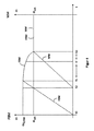
本発明に対応する時間の関数として、開口装置(FBM)および織機(WM)の回転速度の3つの例示的な進行すなわち曲線が、図2に示されている。開口装置は時点t0で始動され、時点t1までに、所定の、特に計算された過速度ωU,FBM(上記参照)まで駆動されすなわち運転される。時点t2では、織機が始動され、時点t2から時点t3までの始動段階では、それは動作回転速度ωarbにまで上昇される。この始動段階の間に、エネルギーは、画定された方法で開口装置から織機に供給され、これに関連する可能な計算方法が上記に示されている。 Three exemplary progressions or curves of the rotational speed of the opening device (FBM) and the weaving machine (WM) as a function of time corresponding to the invention are shown in FIG. The opening device is started at time t0 and is driven or operated by the time t1 to a predetermined, particularly calculated overspeed ω U, F B M (see above). At time t2, the loom is started, and in the start-up phase from time t2 to time t3, it is raised to the operating rotational speed ω arb . During this start-up phase, energy is supplied from the opening device to the loom in a defined manner, the possible calculation methods associated therewith being indicated above.
本発明に重要なのは、開口装置の回転速度曲線の勾配が、織機の始動段階(時点t2とt3との間にある)のうちの後の区間において、前の区間よりも小さいことである。これに関して、後の区間は必ずしも時点t3を境界とする必要はなく、および/または前の区間は必ずしも時点t2を境界とする必要はない(t1がt2より後にある場合にはt1、図4参照)が、時点t2(t1がt2より後にある場合にはt1)とt3との間の周期内の勾配進行を互いに比較することができる。 It is important to the invention that the slope of the rotational speed curve of the shedding device is smaller in the later sections of the start-up phase of the weaving machine (between t2 and t3) than in the preceding sections. In this regard, later sections need not necessarily be bounded at time t3, and / or previous sections need not necessarily be bounded at time t2 (if t1 is later than t2, t1, see FIG. 4). ) Can compare the gradient progressions in the period between time t2 (t1 if t1 is later than t2) and t3 with each other.
図2から、この例示的な実施形態では、実線(ここではFBM’として参照される)で示されている開口装置の回転速度曲線の勾配は、始動段階の全時間スパンを基準とした始動段階の終わりに向かって最も小さくなり、すなわち、曲線は、t2とt3の間の範囲内の時点t3で最も小さい勾配を含む。好ましくは、図2に例としてマークされた時点t2と時点t’との間の開口装置の回転速度曲線の勾配は、時点t’と時点t3との間の時間的平均における勾配よりも小さくない。 From FIG. 2, in this exemplary embodiment, the slope of the rotational speed curve of the aperture device, shown as a solid line (herein referred to as FBM ′), is based on the entire time span of the starting phase Towards the end, i.e. the curve contains the smallest slope at time t3 in the range between t2 and t3. Preferably, the slope of the rotational speed curve of the aperture device between the instant t2 and the instant t 'marked as an example in FIG. 2 is not smaller than the slope in the temporal average between the instant t' and the instant t3. .
また、一時的に、時点t2とt3との間の開口装置の回転速度進行が、勾配が再び小さくなる前に、始動段階のより早いステージで立ち上がり勾配、すなわち立ち上がりスロープを有することも可能である。 It is also possible that temporarily the rotational speed progression of the opening device between the instants t2 and t3 has a rising slope, ie a rising slope, at an earlier stage of the start-up phase before the slope becomes smaller again. .
実線で示された織機の回転速度進行(ここではWM’として参照される)は、上記の計算方法で仮定されたように、図2に傾斜路形状に直線的に上昇するように示されている。織機の別の回転速度進行(ここではWM’’として参照される)は破線で示され、時点t2とt3との間の運転中の回転速度は減少する立ち上がり勾配を含む。このような進行では、織機始動の終わりに向かう電力ピークがそれほど顕著ではないので、電力テークアップは直線的な運転よりも一様である。開口装置の例示的な対応する回転速度曲線(ここではFBM’’として参照される)は、同様に破線で示されている。特に織機の始動段階の終わりに向かう、すなわち時点t3で、織機の始動段階の終わりに向かうエネルギーフィードバックが、織機の回転速度WM’が傾斜路形状に上昇する前述の場合よりも小さいために、回転速度曲線FBM’と比較してより平坦な曲線は、そこでより平坦な織機の曲線WM’’に対応している。 The rotational speed progression of the loom indicated by the solid line (herein referred to as WM ') is shown in FIG. 2 as rising linearly to the ramp shape as assumed in the above calculation method There is. Another rotational speed progression of the weaving machine (referred to herein as WM ") is shown in dashed lines, and the rotational speed during operation between time points t2 and t3 includes a decreasing rising slope. At such a progression, power take-up is more uniform than linear operation, as the power peaks towards the end of loom start are less pronounced. An exemplary corresponding rotational speed curve of the opening device (herein referred to as FBM ") is likewise indicated by a dashed line. The energy feedback towards the end of the start-up phase of the loom, in particular towards the end of the start-up phase of the loom, ie at time t3, is lower than in the previous case where the rotational speed WM 'of the loom rises to the ramp shape The flatter curve in comparison to the velocity curve FBM 'corresponds there to the flatter loom curve WM' '.
さらに、第3の変形例が、図2に一点鎖線で示されている。織機の回転速度曲線(ここではWM’’’として参照される)はS字形状を含み、これは、開口装置の回転速度曲線(ここではFBM’’’として参照される)でも繰り返される。開口装置から織機へのエネルギーフィードバックは、時点t2に隣接するより平坦な各回転速度曲線の後で、特に、織機の回転速度の最も強いすなわち最も鋭い立ち上がりの間に大きくなる。織機の始動段階の終わりに向かって、回転速度進行すなわち曲線FBM’’’およびWM’’’の両方が再び平坦になる。 Furthermore, a third variant is shown in FIG. The rotational speed curve of the weaving machine (herein referred to as WM '' ') comprises an S-shape, which is also repeated in the rotational speed curve of the opening device (herein referred to as FBM' ''). The energy feedback from the opening device to the weaving machine becomes greater after each flatter rotational speed curve adjacent to the instant t2, in particular during the strongest or sharpest rise of the rotational speed of the weaving machine. Toward the end of the start-up phase of the weaving machine, both the rotational speed progression, ie the curves FBM ′ ′ ′ and WM ′ ′ ′, become flat again.
図3には、上述した開口装置の回転速度の極大値が存在する場合が示されている。これが、開口装置の許容最大回転速度を上回っているかどうかをそれぞれ検査しなければならない。 FIG. 3 shows the case where the maximum value of the rotation speed of the above-mentioned opening device exists. It has to be checked whether this exceeds the maximum permissible rotational speed of the opening device.
時点t1が時点t2の後にある場合を図4に示す。最初に説明したように、需要または要求の観点からは、織機は、始動段階のはじめに開口装置の部分に対する支援から利益を得ないので、したがって、織機は、時点t1において開口装置がその計算された過速度に達する前に、(時点t2で)すでに始動され得る。その後、t1からt3の時間間隔で織機にエネルギーを伝達する準備ができていることが重要である。 The case where the time point t1 is after the time point t2 is shown in FIG. As explained at the outset, in terms of demand or demand, the loom does not benefit from the support for the part of the opening device at the beginning of the start-up phase, and therefore the loom has its opening device calculated at time t1. Before reaching overspeed, it can already be started (at time t2). It is then important that the energy be ready to be transmitted to the loom at time intervals t1 to t3.
織機の主駆動装置および開口装置の電子補助駆動装置の起動は、従来技術のコントローラによって引き継がれ、したがって、ここではさらに詳細には説明しない。上記の計算は、記載されたコントローラに接続された計算装置を使用して実行される。 The activation of the main drive of the weaving machine and the electronic auxiliary drive of the opening device is taken over by the controller of the prior art and is therefore not described in further detail here. The above calculations are performed using a computing device connected to the described controller.
本発明は図示され説明された例示的な実施形態に限定されない。特許請求の範囲の範囲内の変更は、これらが異なる例示的な実施形態で図示され説明されていても、特徴の組み合わせとして可能である。 The invention is not limited to the exemplary embodiments shown and described. Modifications within the scope of the claims are possible as a combination of features, even though they are illustrated and described in the different exemplary embodiments.
Claims (9)
前記織機および前記開口装置はコントローラに接続され、
前記織機は主駆動装置によって駆動され、
前記開口装置は電気モータ補助駆動装置によって駆動され、
前記織機および前記開口装置は、エネルギー流伝達のための共通のコンバータ中間回路によって接続され、
前記開口装置は、時点t0で始動され、その動作回転速度を上回る過速度に時点t1まで増加し、時点t1は時点t3の前にあり、
前記織機は、前記時点t0よりも後にある時点t2で始動され、前記織機の始動段階は時点t2から時点t3までの時間間隔にあり、
前記コンバータ中間回路による前記開口装置から前記織機への動力伝達(フィードバック)は、所定の始動段階において実行される、
方法において、
前記開口装置が、前記時点t0と前記時点t1との間で予め定められた過速度まで運転されること、および、
前記開口装置の前記回転速度曲線の勾配が、前記始動段階のうちの前の区間よりも後の区間でより小さくなること、
を特徴とする、方法。 Method for controlled operation of a loom and opening device,
The loom and the opening device are connected to a controller,
The loom is driven by a main drive,
The opening device is driven by an electric motor auxiliary drive,
The loom and the opening device are connected by a common converter intermediate circuit for the energy flow transmitted,
The opening device is started at time t0 and increases to an overspeed above its operating rotational speed up to time t1, which is before time t3;
The loom is started at a point in time t2 after the point in time t0 , and the start-up phase of the loom is in the time interval from the point in time t2 to the point in time t3;
Power transmission (feedback) from the opening device to the loom by the converter intermediate circuit is performed at a predetermined start-up stage,
In the method
The opening device is operated to a predetermined overspeed between the time t0 and the time t1, and
The slope of the rotational speed curve of the opening device being smaller in later sections of the start phase than in the previous sections;
Characterized by how.
Applications Claiming Priority (3)
| Application Number | Priority Date | Filing Date | Title |
|---|---|---|---|
| DE102015102029.7 | 2015-02-12 | ||
| DE102015102029.7A DE102015102029A1 (en) | 2015-02-12 | 2015-02-12 | Starting process for a weaving machine |
| PCT/EP2016/052923 WO2016128517A1 (en) | 2015-02-12 | 2016-02-11 | Starting method for a weaving machine |
Publications (3)
| Publication Number | Publication Date |
|---|---|
| JP2018508662A JP2018508662A (en) | 2018-03-29 |
| JP2018508662A5 JP2018508662A5 (en) | 2019-03-22 |
| JP6510059B2 true JP6510059B2 (en) | 2019-05-08 |
Family
ID=55349836
Family Applications (1)
| Application Number | Title | Priority Date | Filing Date |
|---|---|---|---|
| JP2017542027A Active JP6510059B2 (en) | 2015-02-12 | 2016-02-11 | Starting method of loom |
Country Status (7)
| Country | Link |
|---|---|
| US (1) | US20180023226A1 (en) |
| EP (1) | EP3256628B1 (en) |
| JP (1) | JP6510059B2 (en) |
| CN (1) | CN107208330B (en) |
| DE (1) | DE102015102029A1 (en) |
| RU (1) | RU2664381C1 (en) |
| WO (1) | WO2016128517A1 (en) |
Families Citing this family (3)
| Publication number | Priority date | Publication date | Assignee | Title |
|---|---|---|---|---|
| DE102017221224B3 (en) | 2017-11-27 | 2019-01-17 | Lindauer Dornier Gesellschaft Mit Beschränkter Haftung | Device and method for producing tissue with a loom and two Jacquard machines |
| JP7365098B2 (en) * | 2018-02-21 | 2023-10-19 | 津田駒工業株式会社 | Loom drive control method and drive control device |
| CZ309248B6 (en) * | 2019-06-13 | 2022-06-22 | VÚTS, a.sю | Method of controlling the lifting functions of the main mechanisms of a weaving machine |
Family Cites Families (19)
| Publication number | Priority date | Publication date | Assignee | Title |
|---|---|---|---|---|
| US4131803A (en) * | 1975-11-05 | 1978-12-26 | Toyo Boseki Kabushiki Kaisha | Apparatus for detecting defects in sheet material |
| US4473096A (en) * | 1979-08-06 | 1984-09-25 | Leesona Corporation | Weft end reception system |
| CH641506A5 (en) * | 1980-01-23 | 1984-02-29 | Sulzer Ag | WEAVING MACHINE. |
| US4362189A (en) * | 1981-01-07 | 1982-12-07 | Leesona Corporation | Fluid weft insertion loom monitoring system |
| JPS5959946A (en) * | 1982-09-24 | 1984-04-05 | 日産自動車株式会社 | Control of loom at stopping time thereof in warp yarn send- out apparatus of loom |
| JPH0694614B2 (en) * | 1983-02-25 | 1994-11-24 | 津田駒工業株式会社 | Electric loom feeding method and device |
| US4781221A (en) * | 1985-06-29 | 1988-11-01 | Nissan Motor Co., Ltd. | Mispicked weft yarn removing method and system therefor |
| DE3542650A1 (en) * | 1985-12-03 | 1987-06-04 | Stromag Maschf | Method and device for controlling and/or regulating the operation of starting a weaving machine |
| JP2710046B2 (en) * | 1986-12-04 | 1998-02-10 | 津田駒工業 株式会社 | Warp tension control method for pile loom |
| JPH03161555A (en) * | 1989-11-20 | 1991-07-11 | Toyota Autom Loom Works Ltd | Warp-thereading detection apparatus of loom |
| GB9605059D0 (en) * | 1996-03-09 | 1996-05-08 | Palmer Raymond L | Drive system |
| DE10053079C1 (en) | 2000-10-26 | 2002-05-29 | Dornier Gmbh Lindauer | Method for operating a weaving and shedding machine |
| DE10061717B4 (en) * | 2000-12-12 | 2006-01-26 | Lindauer Dornier Gmbh | Drive arrangement for a weaving machine and shedding machine |
| DE20021049U1 (en) | 2000-12-12 | 2001-03-29 | Dornier Gmbh Lindauer | Drive arrangement for a weaving machine and shedding machine |
| DE10236095B3 (en) * | 2002-08-07 | 2004-02-05 | Lindauer Dornier Gesellschaft Mbh | Loom operation with a number of drives, initially runs the main drive at a slower speed on start-up until it reaches working levels, while the shed drive is accelerated to its working speed and is braked slowly on stopping |
| SE0300809L (en) * | 2003-03-25 | 2004-03-02 | Texo Ab | Device for weaving machine |
| DE102004017106B4 (en) * | 2004-04-02 | 2008-03-13 | Lindauer Dornier Gmbh | Method for determining the kinetic energy of a weaving machine |
| DE102007043142B4 (en) * | 2007-09-11 | 2012-03-08 | Lindauer Dornier Gmbh | Method for shutting down a weaving machine |
| DE102011006368B3 (en) * | 2011-03-29 | 2012-02-16 | Lindauer Dornier Gesellschaft Mit Beschränkter Haftung | Method and loom for shedding |
-
2015
- 2015-02-12 DE DE102015102029.7A patent/DE102015102029A1/en not_active Withdrawn
-
2016
- 2016-02-11 US US15/546,812 patent/US20180023226A1/en not_active Abandoned
- 2016-02-11 EP EP16703979.1A patent/EP3256628B1/en active Active
- 2016-02-11 JP JP2017542027A patent/JP6510059B2/en active Active
- 2016-02-11 RU RU2017131641A patent/RU2664381C1/en not_active IP Right Cessation
- 2016-02-11 CN CN201680010006.4A patent/CN107208330B/en active Active
- 2016-02-11 WO PCT/EP2016/052923 patent/WO2016128517A1/en active Application Filing
Also Published As
| Publication number | Publication date |
|---|---|
| US20180023226A1 (en) | 2018-01-25 |
| WO2016128517A1 (en) | 2016-08-18 |
| RU2664381C1 (en) | 2018-08-16 |
| JP2018508662A (en) | 2018-03-29 |
| DE102015102029A1 (en) | 2016-08-18 |
| EP3256628B1 (en) | 2019-08-07 |
| CN107208330A (en) | 2017-09-26 |
| CN107208330B (en) | 2020-03-20 |
| EP3256628A1 (en) | 2017-12-20 |
Similar Documents
| Publication | Publication Date | Title |
|---|---|---|
| JP6510059B2 (en) | Starting method of loom | |
| US8219256B2 (en) | Bang-bang controller and control method for variable speed wind turbines during abnormal frequency conditions | |
| JP5156029B2 (en) | Wind power generator and control method thereof | |
| CN103534932B (en) | System and method for quick start feeling induction motor | |
| JP2011517264A (en) | Wind power plant operating method with double-fed asynchronous machine and wind power plant with double-fed asynchronous machine | |
| KR101403265B1 (en) | A method in a production system for limiting peak power | |
| JP5954313B2 (en) | Motor control system, control device, and control method | |
| RU2569402C2 (en) | Control system of steam turbine for maintenance of synchronisation and method for its implementation | |
| CN108352794A (en) | The method of shutting down of control for weaving loom and the weaving loom stopped by this processing | |
| US7612518B2 (en) | Inverter apparatus and method of reducing speed of alternating current motor | |
| JP3973608B2 (en) | Bias setting value setting method for warp winding device and warp winding device | |
| KR20180004761A (en) | How to operate a wind turbine | |
| US8686581B2 (en) | Method for operating a wind turbine in the event of the occurrence of a grid fault with a voltage drop and such a wind turbine | |
| JP2000282350A (en) | Starting of loom equipped with electrically-operated main driving device | |
| JPWO2018011863A1 (en) | Inverter device | |
| JP2010126364A (en) | Thread tension adjusting device | |
| JP2018508662A5 (en) | ||
| CN105490599B (en) | Method and apparatus for the leakage inductance for determining double fed induction generators | |
| WO2013058106A1 (en) | Wind power generation device, method for same, and program | |
| JP2009189238A (en) | Drive apparatus and method for its operation | |
| JP6807138B2 (en) | Electric motor control device | |
| JP2009189238A6 (en) | Driving device and driving method of driving device | |
| CN110535395A (en) | A kind of control method and device of motor | |
| JP6783101B2 (en) | Generator controller and generator system using it | |
| JP4075770B2 (en) | Winding bobbin rotational speed control method and inverter |
Legal Events
| Date | Code | Title | Description |
|---|---|---|---|
| A977 | Report on retrieval |
Free format text: JAPANESE INTERMEDIATE CODE: A971007 Effective date: 20180808 |
|
| A131 | Notification of reasons for refusal |
Free format text: JAPANESE INTERMEDIATE CODE: A131 Effective date: 20180817 |
|
| A601 | Written request for extension of time |
Free format text: JAPANESE INTERMEDIATE CODE: A601 Effective date: 20181116 |
|
| A524 | Written submission of copy of amendment under article 19 pct |
Free format text: JAPANESE INTERMEDIATE CODE: A524 Effective date: 20190205 |
|
| TRDD | Decision of grant or rejection written | ||
| A01 | Written decision to grant a patent or to grant a registration (utility model) |
Free format text: JAPANESE INTERMEDIATE CODE: A01 Effective date: 20190305 |
|
| A61 | First payment of annual fees (during grant procedure) |
Free format text: JAPANESE INTERMEDIATE CODE: A61 Effective date: 20190403 |
|
| R150 | Certificate of patent or registration of utility model |
Ref document number: 6510059 Country of ref document: JP Free format text: JAPANESE INTERMEDIATE CODE: R150 |
|
| R250 | Receipt of annual fees |
Free format text: JAPANESE INTERMEDIATE CODE: R250 |
|
| R250 | Receipt of annual fees |
Free format text: JAPANESE INTERMEDIATE CODE: R250 |
|
| R250 | Receipt of annual fees |
Free format text: JAPANESE INTERMEDIATE CODE: R250 |