JP6509562B2 - Improved lead storage battery structure - Google Patents
Improved lead storage battery structure Download PDFInfo
- Publication number
- JP6509562B2 JP6509562B2 JP2014560886A JP2014560886A JP6509562B2 JP 6509562 B2 JP6509562 B2 JP 6509562B2 JP 2014560886 A JP2014560886 A JP 2014560886A JP 2014560886 A JP2014560886 A JP 2014560886A JP 6509562 B2 JP6509562 B2 JP 6509562B2
- Authority
- JP
- Japan
- Prior art keywords
- electrode
- lead
- fiber material
- conductive fiber
- carbon
- Prior art date
- Legal status (The legal status is an assumption and is not a legal conclusion. Google has not performed a legal analysis and makes no representation as to the accuracy of the status listed.)
- Active
Links
Images


Classifications
-
- H—ELECTRICITY
- H01—ELECTRIC ELEMENTS
- H01M—PROCESSES OR MEANS, e.g. BATTERIES, FOR THE DIRECT CONVERSION OF CHEMICAL ENERGY INTO ELECTRICAL ENERGY
- H01M4/00—Electrodes
- H01M4/02—Electrodes composed of, or comprising, active material
- H01M4/14—Electrodes for lead-acid accumulators
- H01M4/16—Processes of manufacture
- H01M4/20—Processes of manufacture of pasted electrodes
-
- H—ELECTRICITY
- H01—ELECTRIC ELEMENTS
- H01M—PROCESSES OR MEANS, e.g. BATTERIES, FOR THE DIRECT CONVERSION OF CHEMICAL ENERGY INTO ELECTRICAL ENERGY
- H01M4/00—Electrodes
- H01M4/02—Electrodes composed of, or comprising, active material
- H01M4/14—Electrodes for lead-acid accumulators
-
- H—ELECTRICITY
- H01—ELECTRIC ELEMENTS
- H01M—PROCESSES OR MEANS, e.g. BATTERIES, FOR THE DIRECT CONVERSION OF CHEMICAL ENERGY INTO ELECTRICAL ENERGY
- H01M4/00—Electrodes
- H01M4/02—Electrodes composed of, or comprising, active material
- H01M4/64—Carriers or collectors
- H01M4/70—Carriers or collectors characterised by shape or form
- H01M4/72—Grids
- H01M4/73—Grids for lead-acid accumulators, e.g. frame plates
-
- H—ELECTRICITY
- H01—ELECTRIC ELEMENTS
- H01M—PROCESSES OR MEANS, e.g. BATTERIES, FOR THE DIRECT CONVERSION OF CHEMICAL ENERGY INTO ELECTRICAL ENERGY
- H01M10/00—Secondary cells; Manufacture thereof
- H01M10/06—Lead-acid accumulators
-
- H—ELECTRICITY
- H01—ELECTRIC ELEMENTS
- H01M—PROCESSES OR MEANS, e.g. BATTERIES, FOR THE DIRECT CONVERSION OF CHEMICAL ENERGY INTO ELECTRICAL ENERGY
- H01M4/00—Electrodes
- H01M4/02—Electrodes composed of, or comprising, active material
- H01M4/36—Selection of substances as active materials, active masses, active liquids
- H01M4/362—Composites
- H01M4/364—Composites as mixtures
-
- H—ELECTRICITY
- H01—ELECTRIC ELEMENTS
- H01M—PROCESSES OR MEANS, e.g. BATTERIES, FOR THE DIRECT CONVERSION OF CHEMICAL ENERGY INTO ELECTRICAL ENERGY
- H01M4/00—Electrodes
- H01M4/02—Electrodes composed of, or comprising, active material
- H01M4/62—Selection of inactive substances as ingredients for active masses, e.g. binders, fillers
- H01M4/628—Inhibitors, e.g. gassing inhibitors, corrosion inhibitors
-
- H—ELECTRICITY
- H01—ELECTRIC ELEMENTS
- H01M—PROCESSES OR MEANS, e.g. BATTERIES, FOR THE DIRECT CONVERSION OF CHEMICAL ENERGY INTO ELECTRICAL ENERGY
- H01M4/00—Electrodes
- H01M4/02—Electrodes composed of, or comprising, active material
- H01M4/64—Carriers or collectors
- H01M4/66—Selection of materials
- H01M4/663—Selection of materials containing carbon or carbonaceous materials as conductive part, e.g. graphite, carbon fibres
-
- H—ELECTRICITY
- H01—ELECTRIC ELEMENTS
- H01M—PROCESSES OR MEANS, e.g. BATTERIES, FOR THE DIRECT CONVERSION OF CHEMICAL ENERGY INTO ELECTRICAL ENERGY
- H01M4/00—Electrodes
- H01M4/02—Electrodes composed of, or comprising, active material
- H01M4/64—Carriers or collectors
- H01M4/66—Selection of materials
- H01M4/665—Composites
- H01M4/667—Composites in the form of layers, e.g. coatings
-
- H—ELECTRICITY
- H01—ELECTRIC ELEMENTS
- H01M—PROCESSES OR MEANS, e.g. BATTERIES, FOR THE DIRECT CONVERSION OF CHEMICAL ENERGY INTO ELECTRICAL ENERGY
- H01M4/00—Electrodes
- H01M4/02—Electrodes composed of, or comprising, active material
- H01M4/64—Carriers or collectors
- H01M4/66—Selection of materials
- H01M4/68—Selection of materials for use in lead-acid accumulators
-
- H—ELECTRICITY
- H01—ELECTRIC ELEMENTS
- H01M—PROCESSES OR MEANS, e.g. BATTERIES, FOR THE DIRECT CONVERSION OF CHEMICAL ENERGY INTO ELECTRICAL ENERGY
- H01M4/00—Electrodes
- H01M4/02—Electrodes composed of, or comprising, active material
- H01M2004/021—Physical characteristics, e.g. porosity, surface area
-
- H—ELECTRICITY
- H01—ELECTRIC ELEMENTS
- H01M—PROCESSES OR MEANS, e.g. BATTERIES, FOR THE DIRECT CONVERSION OF CHEMICAL ENERGY INTO ELECTRICAL ENERGY
- H01M2220/00—Batteries for particular applications
- H01M2220/20—Batteries in motive systems, e.g. vehicle, ship, plane
-
- H—ELECTRICITY
- H01—ELECTRIC ELEMENTS
- H01M—PROCESSES OR MEANS, e.g. BATTERIES, FOR THE DIRECT CONVERSION OF CHEMICAL ENERGY INTO ELECTRICAL ENERGY
- H01M4/00—Electrodes
- H01M4/02—Electrodes composed of, or comprising, active material
- H01M4/04—Processes of manufacture in general
- H01M4/0402—Methods of deposition of the material
- H01M4/0416—Methods of deposition of the material involving impregnation with a solution, dispersion, paste or dry powder
-
- H—ELECTRICITY
- H01—ELECTRIC ELEMENTS
- H01M—PROCESSES OR MEANS, e.g. BATTERIES, FOR THE DIRECT CONVERSION OF CHEMICAL ENERGY INTO ELECTRICAL ENERGY
- H01M4/00—Electrodes
- H01M4/02—Electrodes composed of, or comprising, active material
- H01M4/04—Processes of manufacture in general
- H01M4/0438—Processes of manufacture in general by electrochemical processing
- H01M4/044—Activating, forming or electrochemical attack of the supporting material
- H01M4/0445—Forming after manufacture of the electrode, e.g. first charge, cycling
-
- H—ELECTRICITY
- H01—ELECTRIC ELEMENTS
- H01M—PROCESSES OR MEANS, e.g. BATTERIES, FOR THE DIRECT CONVERSION OF CHEMICAL ENERGY INTO ELECTRICAL ENERGY
- H01M4/00—Electrodes
- H01M4/02—Electrodes composed of, or comprising, active material
- H01M4/62—Selection of inactive substances as ingredients for active masses, e.g. binders, fillers
- H01M4/627—Expanders for lead-acid accumulators
-
- Y—GENERAL TAGGING OF NEW TECHNOLOGICAL DEVELOPMENTS; GENERAL TAGGING OF CROSS-SECTIONAL TECHNOLOGIES SPANNING OVER SEVERAL SECTIONS OF THE IPC; TECHNICAL SUBJECTS COVERED BY FORMER USPC CROSS-REFERENCE ART COLLECTIONS [XRACs] AND DIGESTS
- Y02—TECHNOLOGIES OR APPLICATIONS FOR MITIGATION OR ADAPTATION AGAINST CLIMATE CHANGE
- Y02E—REDUCTION OF GREENHOUSE GAS [GHG] EMISSIONS, RELATED TO ENERGY GENERATION, TRANSMISSION OR DISTRIBUTION
- Y02E60/00—Enabling technologies; Technologies with a potential or indirect contribution to GHG emissions mitigation
- Y02E60/10—Energy storage using batteries
-
- Y—GENERAL TAGGING OF NEW TECHNOLOGICAL DEVELOPMENTS; GENERAL TAGGING OF CROSS-SECTIONAL TECHNOLOGIES SPANNING OVER SEVERAL SECTIONS OF THE IPC; TECHNICAL SUBJECTS COVERED BY FORMER USPC CROSS-REFERENCE ART COLLECTIONS [XRACs] AND DIGESTS
- Y02—TECHNOLOGIES OR APPLICATIONS FOR MITIGATION OR ADAPTATION AGAINST CLIMATE CHANGE
- Y02P—CLIMATE CHANGE MITIGATION TECHNOLOGIES IN THE PRODUCTION OR PROCESSING OF GOODS
- Y02P70/00—Climate change mitigation technologies in the production process for final industrial or consumer products
- Y02P70/50—Manufacturing or production processes characterised by the final manufactured product
Description
本発明は、鉛蓄電池(鉛酸電池、Pb酸電池)、特に、限定するものではないが、ハイブリッド車両用の自動車用電池のための改善された電池構造に関する。 The present invention relates to lead-acid batteries (lead-acid batteries, Pb-acid batteries), and in particular, but not exclusively, to an improved battery structure for automotive batteries for hybrid vehicles.
鉛蓄電池(鉛酸電池、Pb酸電池)は、電池の電極表面での電気化学反応によってエネルギーの保存および放出を行う。フル充電状態における各セルは、元素鉛(Pb)および鉛(IV)二酸化物(PbO2)の電極を、希硫酸(H2SO4)の電解質中に含む。放電状態では、2つの電極が鉛(II)硫酸塩(PbSO4)に変化し、電解質から溶解硫酸が失われ、主に水となる。ペーストプレート構造において、各プレートは、酸化鉛(PbおよびPbO)および希硫酸の混合物を含むペーストが初期に充填された鉛格子からなる。この構造により、セル形成(隣接粒子間の結合が発生する第1の充電および放電サイクル時)時においてペースト中の酸がプレート中の酸化鉛と反応し、その結果、電気伝導度および活性表面積が増加し、よって電池容量も増加する。ペーストは、カーボンブラック、沈降硫酸バリウム(微粒子硫酸バリウム)およびリグノスルホン酸塩も含み得る。 Lead storage batteries (lead acid batteries, Pb acid batteries) store and release energy by an electrochemical reaction on the electrode surface of the battery. Each cell at full charge contains an electrode of elemental lead (Pb) and lead (IV) dioxide (PbO 2 ) in the electrolyte of dilute sulfuric acid (H 2 SO 4 ). In the discharge state, the two electrodes change to lead (II) sulfate (PbSO 4 ), and the electrolyte loses dissolved sulfuric acid, mainly to water. In the paste plate structure, each plate consists of a lead grid initially filled with a paste containing a mixture of lead oxide (Pb and PbO) and dilute sulfuric acid. This structure causes the acid in the paste to react with the lead oxide in the plate during cell formation (during the first charge and discharge cycles where bonding between adjacent particles occurs), resulting in conductivity and active surface area The battery capacity is also increased. The paste may also contain carbon black, precipitated barium sulfate (particulate barium sulfate) and lignosulfonates.
自動車排出の低下および/または燃料効速度の向上への世界的要求に起因する車両のハイブリッド化により、車両電池への要求も高まっている。最も一般的な車両電池として、鉛蓄電池がある。例えば、欧州連合によって設定された長期排出目的は、新車の場合は2020年までに95gの二酸化炭素/km以下に定められている。 The demand for vehicle batteries is also increasing due to the hybridisation of vehicles due to the global demand for reduced vehicle emissions and / or improved fuel efficiency. The most common vehicle battery is the lead acid battery. For example, the long-term emission targets set by the European Union are set at 95 g carbon dioxide / km or less by 2020 for new vehicles.
多くの新たな内燃機関(ガソリン、ディーゼルまたはガス)によって動力供給される車両にも、アイドリング排除機能があり、エンジンが、車両の静止時または低速走行時においてオフに切り替わるように構成されている。このような車両は、ストップ/スタート車両またはマイクロハイブリッド車両と呼ばれる。各エンジンの再起動時に電池からエネルギーが引き出されるが、このようなエネルギー引き出しが、再充電によるエネルギー交換よりも高速で発生した場合、通勤時など、エンジンがオンとなる期間が比較的短い時間に、電池の充電(または充電状態)を維持できなくなる。また、空調、ラジオなどの車両内の他の機能(「ホテル充填」と呼ぶ)の維持のために車両エンジンにオフとなっている期間であっても、電流が電池から引き出される。電池の充電が十分に低下すると、車両電池管理システムがアイドリング排除機能よりも優先され、これにより、電池の充電状態が回復するまで、エンジンストップ/スタートが回避される。そのため、例えば通勤の渋滞時にも電池の充電を維持するためには、このようなストップ/スタート車両またはマイクロハイブリッド車両用の電池の動的電荷受容性(DCA)速度を高くする必要が出てくる。動的電荷受容性(DCA)比とは、電池が充電を受容する比を指す。 Vehicles powered by many new internal combustion engines (gasoline, diesel or gas) also have an idling exclusion function and the engine is configured to switch off when the vehicle is stationary or at low speeds. Such vehicles are called stop / start vehicles or micro-hybrid vehicles. Energy is drawn from the battery when each engine restarts, but if such energy drawing occurs faster than the energy exchange by recharging, the time during which the engine is turned on is relatively short, such as commuting time. , Can not maintain the charge (or charge state) of the battery. Also, current is drawn from the battery even during periods when the vehicle engine is off to maintain other functions in the vehicle such as air conditioning, radio and the like (referred to as "hotel filling"). If the battery charge drops sufficiently, the vehicle battery management system will take precedence over the idle exclusion feature, thereby avoiding engine stop / start until the battery charge is restored. Therefore, it is necessary to increase the dynamic charge acceptance (DCA) speed of batteries for such stop / start vehicles or micro hybrid vehicles, for example, in order to maintain battery charging even during commuting congestion. . Dynamic charge acceptance (DCA) ratio refers to the ratio at which a battery accepts charge.
ハイブリッド化レベルが高い車両(例えば、内燃機関および電動機双方を含む車両)は典型的には、回生制動を含む。回生制動においては、制動力が発電機から付加されると、発電機からの電気エネルギーが車両電池内へ保存される。車両電池の充電は、(ここでは交流発電機を含む)発電機も駆動する内燃機関が動作していない期間における回生制動からの電流のみによって行われる。回生制動下においては、比較的高い充電電流が車両電池へ短期間にわたって供給されるため、回生制動を用いたハイブリッド車両用電池のDCAも高くする必要が出てくる。完全な電気車両にも、回生制動が含まれる。 Vehicles with high levels of hybridization (eg, vehicles that include both an internal combustion engine and an electric motor) typically include regenerative braking. In regenerative braking, when a braking force is applied from the generator, electrical energy from the generator is stored in the vehicle battery. The charging of the vehicle battery takes place only by means of the current from the regenerative braking during periods when the internal combustion engine which also drives the generator (including the alternator here) is not operating. Under regenerative braking, a relatively high charging current is supplied to the vehicle battery for a short period of time, so it is necessary to increase the DCA of the battery for hybrid vehicles using regenerative braking. Complete electric vehicles also include regenerative braking.
ハイブリッド車両の充電システムは、エンジン駆動発電機を用いて、車両電池の充電状態を、フル充電未満に(例えば、約80%の充電状態に)維持するように構成されている。そのため、回生制動からのさらなる充電エネルギーを受容するために使用可能な容量が一般的に存在する。しかし、放電サイクルおよび(フル充電未満の)充電サイクルが多く繰り返されると、電池のDCAが典型的には経時的に低下し、AGM電池の場合、数千サイクル内において約0.1〜0.3A/Ah(または0.1〜0.3C)で動作することが多い。このような電荷受容性の低下に起因して、車両の燃料節減能力が低下する。自動車メーカーが理想とする電池は、スタート/ストップ機能および回生制動機能の燃料節減の可能性を最大にするため、5〜10秒の期間にわたって2A/ahまたはさらには3A/Ahまでを受容することができる電池である。しかし、0.1〜0.3A/Ahを超える向上が得られれば、かなりの向上といえる。典型的には、ハイブリッド車両の充電システムは、電池からの放電の後、(エンジン駆動発電機により)電池を充電するように配置されていることが多い。一般的に、車両の電池管理システムは、電池のフル充電(または「再調整」)を定期的に行って、電池DCAを、例えば3ヶ月毎に回復させる。理想的な鉛蓄電池(特に、ハイブリッド車両用のもの)は、定期的なフル充電を必要とせずにDCAを維持するか、または、少なくともより高速のDCAを再調整サイクル間に維持する。 Hybrid vehicle charging systems are configured using an engine driven generator to maintain the state of charge of the vehicle battery below full charge (e.g., at about 80% charge). As such, there is generally a capacity available to receive additional charging energy from regenerative braking. However, if the discharge cycle and the charge cycle (less than full charge) are repeated many times, the battery DCA typically drops over time, and in the case of AGM batteries, about 0.1 to 0. It often operates at 3A / Ah (or 0.1 to 0.3C). Due to such a decrease in charge acceptance, the fuel saving ability of the vehicle is reduced. Batteries ideal for automakers should accept up to 2 A / ah or even 3 A / Ah over a period of 5 to 10 seconds in order to maximize the fuel savings potential of the start / stop function and the regenerative braking function. Is a battery that can However, if an improvement exceeding 0.1 to 0.3 A / Ah is obtained, it can be said that it is a considerable improvement. Typically, the charging system of a hybrid vehicle is often arranged to charge the battery (by means of an engine driven generator) after discharging the battery. Generally, a vehicle's battery management system periodically performs a full charge (or "re-adjustment") of the battery to recover the battery DCA, for example, every three months. An ideal lead-acid battery (especially for hybrid vehicles) maintains DCA without the need for regular full charge or at least maintains faster DCA during the reconditioning cycle.
鉛蓄電池において、DCAは、陰極における充電反応によって主に決定される。 In lead acid batteries, the DCA is mainly determined by the charge reaction at the cathode.
電池が、例えば、より高い体積エネルギー密度などの他の要求を満たすべきこともある。体積エネルギー密度(VED)とは、電極の単位体積あたりに供給されるエネルギーを指す。閉鎖型の鉛蓄電池系の場合、水消費の低減も必要となる。詳細には、自動車用電池は、低温におけるエンジン起動のために高電流を送達できる必要がある。コールドクランキングアンペア(CCA)試験において、電池のそのような能力が試験される。 The battery may have to meet other requirements, such as higher volumetric energy density, for example. Volumetric energy density (VED) refers to the energy delivered per unit volume of the electrode. In the case of closed lead storage battery systems, it is also necessary to reduce water consumption. In particular, automotive batteries need to be able to deliver high current for engine startup at low temperatures. In the cold cranking amps (CCA) test, such ability of the battery is tested.
米国特許第7569514号に、活性炭を吸収ガラスマット電池中の電極として用いて硫酸化を解消し、これにより、電池の動的電荷受容性能力を増加させる例が記載されている。 U.S. Pat. No. 7,695,514 describes the use of activated carbon as an electrode in an absorbent glass mat cell to eliminate sulfation thereby increasing the cell's dynamic charge acceptance capability.
米国特許第4429442号に、アクティブマスの機械的完全性を向上させるための、金属格子およびアクティブマスと、アクティブマス側の炭繊維材料とを含む鉛蓄電池プレートが記載されている。 U.S. Pat. No. 4,429,442 describes a lead-acid battery plate comprising a metal grid and an active mass and a carbon fiber material on the active mass side to improve the mechanical integrity of the active mass.
米国特許第4342343号に、ペーストプレート面上に相互接続された炭素繊維を備えた負鉛酸保存電池プレートが記載されている。製造時に、繊維をペーパーキャリアへ固定した後にプレートへ押圧することにより、成形性が向上される。 U.S. Pat. No. 4,342,343 describes a negative lead acid storage cell plate with carbon fibers interconnected on a paste plate surface. At the time of manufacture, by fixing the fibers to the paper carrier and then pressing them against the plate, the formability is improved.
米国特許第6617071号に、格子プレート表面上に形成された導電性ポリマーマトリクスを有する電極が記載されている。この電極に、導電性ポリマーマトリクスは、超微細粒子またはナノ粒子の活性材料を含む。 U.S. Pat. No. 6,617,071 describes an electrode having a conductive polymer matrix formed on the surface of a grid plate. To this electrode, the conductive polymer matrix comprises ultrafine particle or nanoparticle active material.
本出願人らの国際公開第2011/078707号に、繊維間間隔のフィラメントの導電性繊維材料と、繊維へ取り付けられたP粒子の導電性鎖とを電流収集器としての含む鉛蓄電池が開示されている。このような構成により、改善された電池性能(特にDCA)が得られる。 The applicant's WO 2011/078707 discloses a lead-acid battery comprising as the current collector a conductive fiber material of interfilamentary spacing filaments and a conductive chain of P particles attached to the fibers. ing. Such a configuration results in improved battery performance (especially DCA).
本発明の少なくとも一部の実施形態の目的は、改善されたまたは少なくとも代替的な電極および/またはセルおよび/または電池(特に用途実施限定するものではないが、ハイブリッド車両内における用途に適したもの)ならびに/あるいはその製造方法を提供することにある。 The object of at least some embodiments of the present invention is to provide improved or at least alternative electrodes and / or cells and / or batteries (in particular but not exclusively application-specific but suitable for use in hybrid vehicles) And / or providing a method of manufacturing the same.
広範にいえば、一態様において、本発明は、鉛蓄電池(鉛酸電池、Pb酸電池)またはセルを含む。鉛蓄電池またはセルは、少なくとも1つの(非コンポジットまたはコンポジット)電極を含む。少なくとも1つの(非コンポジットまたはコンポジット)電極は、電流収集器としての導電性繊維材料と、鉛の質量充填比とを含む。フル充電時における導電性繊維材料の(鉛および導電性繊維間の孔部が占める部分体積である)空隙率は、少なくとも約0.3である。導電性繊維の質量に対する(任意の形態の)鉛の質量充填比は、体積比に変換した場合、約0.7:1または約1:1〜約15:1または約10:1の範囲であり(それぞれ、電極の少なくとも大部分にわたり、より好適には電極のほぼ全体にわたる)。 Broadly speaking, in one aspect, the present invention comprises a lead acid battery (lead acid battery, Pb acid battery) or a cell. Lead acid batteries or cells contain at least one (non-composite or composite) electrode. At least one (non-composite or composite) electrode comprises a conductive fiber material as a current collector and a mass loading ratio of lead. The porosity (which is the partial volume occupied by the pores between the lead and the conductive fibers) of the conductive fiber material at full charge is at least about 0.3. The weight loading ratio of lead (in any form) to the weight of the conductive fiber, when converted to a volume ratio, is in the range of about 0.7: 1 or about 1: 1 to about 15: 1 or about 10: 1 (Each over at least a majority of the electrodes, more preferably over substantially the entire electrode).
広範にいえば、別の態様において、本発明は、鉛蓄電池またはセルの製造方法を含む。この製造方法は、少なくとも1つの(非コンポジットまたはコンポジット)電極を形成することを含む。少なくとも1つの(非コンポジットまたはコンポジット)電極は、電流収集器として導電性繊維材料を含む。フル充電時における導電性繊維材料の(鉛および導電性繊維間の孔部が占める部分体積である)空隙率は少なくとも約0.3である。導電性繊維の質量に対する鉛の質量充填比は、体積比に変換した場合、約0.7:1または約1:1〜約15:1または約10:1の範囲である。 Broadly speaking, in another aspect, the invention comprises a method of making a lead acid battery or cell. The manufacturing method comprises forming at least one (non-composite or composite) electrode. At least one (non-composite or composite) electrode comprises a conductive fiber material as a current collector. The porosity (which is the partial volume occupied by the pores between the lead and the conductive fibers) of the conductive fiber material at full charge is at least about 0.3. The mass loading ratio of lead to the mass of conductive fiber, when converted to a volume ratio, ranges from about 0.7: 1 or about 1: 1 to about 15: 1 or about 10: 1.
一部の実施形態において、空隙率は、約0.3〜約0.9、約0.3〜約0.85であり、より好適には約0.3〜約0.8であり、より好適には約0.5〜約0.98であり、さらに好適には約0.8〜約0.95である。 In some embodiments, the porosity is about 0.3 to about 0.9, about 0.3 to about 0.85, more preferably about 0.3 to about 0.8, and more Preferably, it is about 0.5 to about 0.98, more preferably about 0.8 to about 0.95.
一部の実施形態において、活性材料の金型体積充填比を導電性繊維に対するPbに変換した場合、約0.7:1または約1:1〜約7:1であり、または約1.5:1〜約5:1であり、または約2:1〜約4:1である。 In some embodiments, when the mold volume filling ratio of the active material is converted to Pb to conductive fibers, it is about 0.7: 1 or about 1: 1 to about 7: 1, or about 1.5. 1 to about 5: 1, or about 2: 1 to about 4: 1.
典型的には、空隙率は、鉛と炭素との間の通路として存在することができ、これにより、鉛粒子を炭素繊維それぞれの間に形成することができる。一部の実施形態において、導電性繊維間の平均間隔は約0.5〜約10であり、より好適には約1〜約5の繊維径である。一部の実施形態において、繊維間の平均繊維間間隔は50ミクロン未満または20ミクロン未満である。好適には、平均繊維間間隔は少なくとも材料の大部分上にあり、より好適には実質的に金型材料全体上にある。好適な実施形態において、平均繊維径は、約20ミクロン未満または約10ミクロン未満である。 Typically, porosity can be present as a passage between lead and carbon, whereby lead particles can be formed between each of the carbon fibers. In some embodiments, the average spacing between conductive fibers is about 0.5 to about 10, more preferably about 1 to about 5 fiber diameters. In some embodiments, the average inter-fiber spacing between fibers is less than 50 microns or less than 20 microns. Preferably, the average interfiber spacing is at least on the majority of the material, and more preferably substantially over the entire mold material. In preferred embodiments, the average fiber diameter is less than about 20 microns or less than about 10 microns.
広範にいえば、別の態様において、本発明は、鉛蓄電池またはセルを含む。鉛蓄電池またはセルは、少なくとも1つの(非コンポジットまたはコンポジット)電極を含む。少なくとも1つの(非コンポジットまたはコンポジット)電極は、電流収集器として導電性繊維材料を含む。フル充電時における導電性繊維材料の(鉛および導電性繊維間の孔部が占める部分体積である)空隙率は少なくとも約0.3である。導電性繊維材料は、鉛の量の(任意の形態の)(それぞれが電極の少なくとも大部分にわたる)導電性繊維の量に対する充填比を含む。導電性繊維は、空隙率のプロット(x軸)上の点を規定する。充填比に対して、鉛の量の導電性繊維の量に対する充填比(y軸)が設けられる。充填比に対する充填比(y軸)は、プロット上の1つの線によって規定される領域内において約98%のx軸空隙率値から約−1/0.02の傾きを以て延び、プロット上の別の線によって規定される領域内において約70%のx軸空隙率値から約−1/0.3の傾きを以て延びる。 Broadly speaking, in another aspect, the invention comprises a lead acid battery or cell. Lead acid batteries or cells contain at least one (non-composite or composite) electrode. At least one (non-composite or composite) electrode comprises a conductive fiber material as a current collector. The porosity (which is the partial volume occupied by the pores between the lead and the conductive fibers) of the conductive fiber material at full charge is at least about 0.3. The conductive fiber material includes a fill ratio of the amount of lead (in any form) to the amount of conductive fiber (each over at least a majority of the electrodes). The conductive fibers define points on the void fraction plot (x-axis). For the fill ratio, a fill ratio (y-axis) to the amount of conductive fiber for the amount of lead is provided. The fill ratio to the fill ratio (y-axis) extends from an x-axis porosity value of about 98% with a slope of about -1 / 0.02 in the region defined by one line on the plot and another on the plot Extends from an x-axis porosity value of about 70% with a slope of about -1 / 0.3 within the area defined by the line of.
一部の実施形態において、導電性繊維の質量に対する鉛の空隙率および質量充填比は、体積比に変換した場合、プロット上の点を共に規定する。このプロット上の点は、1つの線によって規定された約97%のx軸空隙率値から約−1/0.03の傾きで約80%のx軸空隙率値から約−1/0.2の傾きで別の線までの領域内に入るか、あるいは、1つの線によって規定された96%のx軸空隙率値から−1/0.04の傾きで85%のx軸空隙率値から約−1/0.15の傾きで別の線までの領域内に入る。 In some embodiments, the porosity and mass loading ratio of lead to the mass of conductive fibers together define points on the plot when converted to volume ratios. The points on this plot range from about 97% x-axis porosity value defined by one line to about 80% x-axis porosity value with a slope of about -1 / 0.03 to about -1/0. Enter an area up to another line with a slope of 2 or 85% x-axis porosity value with a slope of -1 / 0.04 from the 96% x-axis porosity value defined by one line Into an area from the point of about −1 / 0.15 to another line.
広範にいえば、別の態様において、本発明は、少なくとも1つの(非コンポジットまたはコンポジット電極を含む鉛蓄電池またはセルを含む。少なくとも1つの(非コンポジットまたはコンポジット電極は、電流収集器として炭素繊維材料を含む。炭素繊維材料の炭素繊維体積分率は、40%未満である。鉛の量の(任意の形態の)炭素繊維の量に対する充填比は、0.5を超える(それぞれ、電極の少なくとも大部分にわたり、より好適には電極のほぼ全体にわたる)。 Broadly stated, in another aspect, the invention comprises at least one lead-acid battery or cell comprising a non-composite or composite electrode. At least one (non-composite or composite electrode is a carbon fiber material as a current collector) The carbon fiber volume fraction of the carbon fiber material is less than 40% The filling ratio of the amount of lead to the amount of carbon fiber (of any form) is more than 0.5 (respectively at least of the electrodes For the most part, more preferably for almost the entire electrode).
一部の実施形態において、炭素繊維体積分率は30%未満であり、鉛の炭素繊維に対する質量充填比を体積比に変換して得られる値は0.7を超え、または、炭素繊維体積分率は20%未満であり、鉛の炭素繊維に対する質量充填比を体積比に変換して得られる値は1:1を超える。 In some embodiments, the carbon fiber volume fraction is less than 30%, and the value obtained by converting the mass filling ratio of lead to carbon fiber to a volume ratio is greater than 0.7, or the carbon fiber volume integral The ratio is less than 20%, and the value obtained by converting the mass filling ratio of lead to carbon fiber into a volume ratio is more than 1: 1.
広範にいえば、別の態様において、本発明は、少なくとも1つの(コンポジット)電極および金属格子を含む鉛蓄電池またはセルを含む。少なくとも1つの(コンポジット)電極は、電流収集器として導電性繊維材料を含む。電極はまた、電流を生成する電解質アクティブマスを含む。電流を生成する電解質アクティブマスのうち少なくとも20%は、導電性繊維材料中に存在する。 Broadly stated, in another aspect, the invention comprises a lead-acid battery or cell comprising at least one (composite) electrode and a metal grid. At least one (composite) electrode comprises a conductive fiber material as a current collector. The electrodes also include an electrolyte active mass that produces an electrical current. At least 20% of the electrolyte active mass generating the current is present in the conductive fiber material.
一部の実施形態において、アクティブマスのうち少なくとも40%、50%、80%または80%以下量が、導電性繊維材料中に存在する。よって、アクティブマスの80%、60%、50%または20%未満を金属格子中に分散させることができる。 In some embodiments, at least 40%, 50%, 80% or 80% or less of the active mass is present in the conductive fiber material. Thus, less than 80%, 60%, 50% or 20% of the active mass can be dispersed in the metal lattice.
一部の実施形態において、導電性繊維材料は炭素繊維材料を含み、金属格子は鉛格子を含む。 In some embodiments, the conductive fiber material comprises a carbon fiber material and the metal grid comprises a lead grid.
一部の実施形態において、導電性繊維材料は、金属格子のうち少なくとも1つのいずれかの側部上の複数の層として存在する。あるいは、導電性繊維材料は、金属格子の片側上の単一の層として存在する。 In some embodiments, the conductive fiber material is present as multiple layers on either side of at least one of the metal grids. Alternatively, the conductive fiber material is present as a single layer on one side of the metal grid.
金属格子は、類似の表面積を持ち得、または特に主要面において導電性繊維材料成分に対して類似の高さおよび幅寸法を持ち得る。しかし、別の実施形態において、金属格子は、より小さな寸法を持ち得(例えば、より小さな高さおよび幅寸法)、また、そのいずれかの側上において上において2つのより大きな炭素繊維層間において例えばより幅狭鉛ストリップを含み得る。 The metal grids may have similar surface areas, or may have similar height and width dimensions relative to the conductive fiber material component, particularly in major planes. However, in another embodiment, the metal grid may have smaller dimensions (e.g. smaller height and width dimensions) and also on two of its larger carbon fiber layers, e.g. on either side thereof It may include narrower lead strips.
炭素繊維層は、格子が炭素繊維層からの電流を受容できるように金属格子へ導電的に接続され、電極へ外部接続される。 The carbon fiber layer is conductively connected to the metal grid and externally connected to the electrodes such that the grid can receive the current from the carbon fiber layer.
導電性繊維材料は、(交差する縦横繊維を含む)織物材料、ニット材料、または不織材料(例えば、フェルト材料)であり得る。陽極または電極、陰極または電極あるいはこれら両方を、導電性繊維材料の1つ以上の層によって形成することができる。好適には、導電性繊維の材料密度も、鉛の材料密度よりも小さい。電流収集器材料は、炭素繊維材料を含み得る(例えば、織物またはニットまたはフェルトまたは不織炭素繊維織物)。炭素繊維電流収集器の材料を十分な温度まで熱処理することにより、電気伝導度を高めることができる。熱処理は、電気アーク放電によって行われ得る。典型的には、導電性繊維材料は、材料の主要面において長さおよび幅寸法を有し、材料の主要面に対して垂直に深さを有する。電流収集器繊維材料の平均深さは、少なくとも0.2mmまたは少なくとも1mmおよび/または5mmまたは3mmまたは2mm未満であり得る。電流収集器は、導電性繊維材料の複数の層を含み得る。電流収集器材料のバルク抵抗率は10Ωmm未満であり、好適には1Ωmmまたは0.1Ωmm未満である。 The conductive fiber material can be a woven material (including intersecting longitudinal and lateral fibers), a knit material, or a non-woven material (eg, a felt material). The anode or the electrode, the cathode or the electrode or both may be formed by one or more layers of conductive fiber material. Preferably, the material density of the conductive fibers is also smaller than the material density of lead. The current collector material may comprise carbon fiber material (e.g. woven or knit or felt or non-woven carbon fiber woven). Electrical conductivity can be enhanced by heat treating the carbon fiber current collector material to a sufficient temperature. Heat treatment may be performed by electric arc discharge. Typically, the conductive fiber material has a length and a width dimension on the major surface of the material and a depth perpendicular to the major surface of the material. The average depth of the current collector fiber material may be at least 0.2 mm or at least 1 mm and / or less than 5 mm or 3 mm or 2 mm. The current collector may include multiple layers of conductive fiber material. The bulk resistivity of the current collector material is less than 10 ohm mm, preferably less than 1 ohm mm or 0.1 ohm mm.
広範にいえば、別の態様において、本発明は、少なくとも1つの電極および金属格子を含む鉛蓄電池またはセルを含む。少なくとも1つの電極は、電流収集器として導電性繊維材料として含む。電極はまた、電流を生成する電解質アクティブマスを含む。導電性繊維材料のバルク抵抗率は10Ωmm未満である。 Broadly stated, in another aspect, the invention comprises a lead-acid battery or cell comprising at least one electrode and a metal grid. At least one electrode is included as a conductive fiber material as a current collector. The electrodes also include an electrolyte active mass that produces an electrical current. The bulk resistivity of the conductive fiber material is less than 10 Ωmm.
少なくとも一部の実施形態において、本発明の電極構造を含むセルおよび/または電池は、改善されたまたは比較的高いDCAおよびCCA双方を持ち得、かつ/または、より多数の充電/放電サイクルでDCAまたはより高速のDCAを維持し得るため、ハイブリッド車両内における用途に特に適している。上記に代えてあるいは上記に加えて、本発明の上記または他の実施形態のセルおよび/または電池は、より低い水消費および/または改善されたまたは比較的高いVEDおよび/または改善された電池寿命を持ち得る。 In at least some embodiments, cells and / or batteries comprising the electrode structures of the present invention may have both improved or relatively high DCA and CCA, and / or DCA with more charge / discharge cycles. Or because it can maintain a higher speed DCA, it is particularly suitable for use in hybrid vehicles. Alternatively or additionally, the cells and / or batteries of the above or other embodiments of the present invention have lower water consumption and / or improved or relatively high VED and / or improved battery life Can have
本明細書中において用いられる「含む」という用語は、「少なくとも部分的に〜からなる」ことを意味する。本明細書中において「含む」という用語を含む記述を解釈する場合、当該用語によって指定される特徴以外の特徴または当該用語によって指定される特徴も存在し得る。関連する用語(例えば、「comprise」および「comprises」)も同様に解釈されるべきである。 The term "comprising" as used herein means "consisting at least in part of". When the description including the term "including" is interpreted in the present specification, features other than the features designated by the term or features designated by the term may be present. Related terms (eg, "comprise" and "comprises") should be interpreted similarly.
添付図面を参照して、例示として本発明をさらに説明する。 The invention will be further described by way of example with reference to the accompanying drawings.
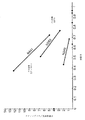
図1を参照すると、図1は、炭素に対する活性材料の比(体積比)対空隙率のチャートを示す。一実施形態において、本発明に係る鉛蓄電池(鉛酸電池、Pb酸電池)またはセルは、電流収集器として導電性繊維材料を含む少なくとも1つの電極と、導電性繊維の質量に対する(任意の形態の)鉛の質量充填比とを含む。この導電性繊維材料は、(鉛および導電性繊維間の孔部が占める部分体積である)空隙率を含む。この空隙率は、フル充電時に少なくとも約0.3である。導電性繊維の質量に対する鉛の質量充填比を体積比に変換した場合、約0.7:1または約1:1〜約15:1または約10:1の範囲内にある(ただし、フル充電時に全活性材料からPbへの完全変換を想定した場合)。一部の実施形態において、空隙率は、約0.3〜0.9であるか、約0.3〜約0.85であるか、約0.3〜約0.80であるか、約0.5〜約0.98であるか、約0.7〜0.95であるか、約0.5〜0.98であるか、または約0.8〜約0.95であり、活性材料の体積充填比を導電性繊維に対するPbに変換した場合、約0.7:1または約1:1〜約7:1であるか、約1.5:1〜約5:1であるか、または約2:1〜約3:1である。 Referring to FIG. 1, FIG. 1 shows a chart of the ratio of active material to carbon (volume ratio) to porosity. In one embodiment, the lead acid battery (lead acid battery, Pb acid battery) or cell according to the present invention comprises at least one electrode comprising a conductive fiber material as a current collector, and the weight of the conductive fiber (any form And the mass filling ratio of lead). The conductive fiber material includes a porosity (which is the partial volume occupied by the pores between the lead and the conductive fibers). This porosity is at least about 0.3 at full charge. When the mass loading ratio of lead to the mass of the conductive fiber is converted to a volume ratio, it is in the range of about 0.7: 1 or about 1: 1 to about 15: 1 or about 10: 1 (but fully charged) Sometimes assuming complete conversion of all active material to Pb). In some embodiments, the porosity is about 0.3 to 0.9, about 0.3 to about 0.85, about 0.3 to about 0.80, or about 0.5 to about 0.98, about 0.7 to 0.95, about 0.5 to 0.98, or about 0.8 to about 0.95, active If the volume filling ratio of the material is converted to Pb to conductive fibers, is it about 0.7: 1 or about 1: 1 to about 7: 1, or about 1.5: 1 to about 5: 1? Or about 2: 1 to about 3: 1.
炭素体積に対する活性材料体積の比とは、導電性繊維マトリックス中のPb含有活性材料の体積を指す。空隙率とは、活性材料の粒子および導電性繊維マトリックス間の空隙容量を全体的体積で除算した値を示す。図1中、後続の実験例に記載される複数の異なる電極の場合の固体体積比対空隙率を示す。図1により、異なるマトリックス空隙率、このマトリックス空隙率を固体活性材料(例えばペースト)で充填する範囲の変動、および充電状態の変動が可能となる。各線は、所与の炭素マトリックスに含まれる2つの極端な形態の活性材料の体積比と空隙率との間において描かれている。ほとんどの電気化学サイクルの場合、これらの2つの形態は、PbおよびPbSO4である。特定の炭素マトリックスによって構成された電極は、チャート上の単一の線を占有し、活性材料を含まないマトリックス空隙率の点を通過する。活性材料の充填の範囲(および例えばPbSO4またはPb中の形態)は、異なる形態の異なる密度およびそれぞれの存在する量を考慮することによって(直線状の)線上において電極が(現在)表される点を決定する。例えば、マトリックスに初期にPbSO4をロードした後にPbへフル充電が行われた場合、この形成は、「フル放電」から「フル充電」の線の一部に沿った移動によって表される。マトリックスに初期にPbOをロードした後にフル充電を行ってこれをPbに変換した場合、PbOからPbへの経路を表す異なる線が描かれる。しかし、このPbへの第1の変換後、任意の後続のサイクルにおいて追随される経路は、PbとPbSO4との間の線を追随する。そのため、このフル充電点がオンになってからの放電/充電は、初期にPbSO4でロードされたときの同じ線に沿った経路によって表される。フル充電されている場合(すなわち、100%Pbの場合)のみにおいて、PbOを前駆体として用いた電極がより有用なPbSO4/Pb線上において表され、その後(すなわち、さらなるサイクルにおいて)電極経路がその線上に設けられる。図1中に349、363および441として示す線は、後続の実験例中に記載する構造を有する電極用のものである。各線の最下点は、全てのロードされた活性材料がPbに変換される条件を示す。 The ratio of active material volume to carbon volume refers to the volume of Pb-containing active material in the conductive fiber matrix. The porosity indicates a value obtained by dividing the void volume between the particles of the active material and the conductive fiber matrix by the total volume. FIG. 1 shows the solid volume ratio versus porosity for a plurality of different electrodes described in the subsequent experiments. FIG. 1 allows different matrix porosity, variation of the range of filling of this matrix porosity with solid active material (eg paste), and variation of the state of charge. Each line is drawn between the volume ratio and the porosity of the two extreme forms of active material contained in a given carbon matrix. For most electrochemical cycles, these two forms are Pb and PbSO 4 . The electrode constituted by the particular carbon matrix occupies a single line on the chart and passes through the points of matrix porosity without active material. The range of loading of the active material (and for example the form in PbSO 4 or Pb) is represented (currently) on the line by taking into account the different densities of the different forms and the respective amounts present Determine the points. For example, if the Pb is fully charged after the initial loading of PbSO 4 into the matrix, this formation is represented by the movement along a portion of the "full discharge" to "full charge" line. If the matrix is initially loaded with PbO and then fully charged to convert it to Pb, then different lines are drawn that represent the PbO to Pb path. However, after this first conversion to Pb, the path followed in any subsequent cycle follows the line between Pb and PbSO 4 . Therefore, the discharge / charge after this full charge point is turned on is represented by the path along the same line when initially loaded with PbSO 4 . An electrode using PbO as a precursor is represented on the more useful PbSO 4 / Pb line only when fully charged (ie in the case of 100% Pb) and the electrode path is then (that is, in a further cycle) It is provided on the line. The lines shown as 349, 363 and 441 in FIG. 1 are for electrodes having the structure described in the subsequent experiments. The lowest point of each line indicates the conditions under which all loaded active material is converted to Pb.
鉛酸セルまたは電池の電極内の空隙率は、活性材料(すなわち、酸)のうち1つを含むことと、電子の供給または受容を行う表面へのイオンの接近を可能にすることとの双方において重要である。この体積を、電解質を含む電極の部分の全体的体積の一部(「空隙率」)として表す。導電性繊維(例えば、炭素繊維)の体積に対する鉛の量の比は、電荷の生成または電荷の受容が可能な物質(Pb)と、電子のための導管を提供しかつ任意選択的に電気化学反応のための触媒表面でもある導電性繊維(例えば、炭素繊維)の物質との間のバランスを指す。この比は、体積比と呼ばれ得る。(Pbのみが存在する)フル充電状態およびフル放電状態(PbSO4のみ)について、体積および質量比双方を計算することができる。通常のサイクル充電および放電において、100%のPbSO4との反応前に放電が完了する。任意の所与の電極は、2つのパラメータによって特徴付けることができる(すなわち、1.活性材料の充填前のマトリックス空隙率(またはより簡便には、この空隙率から1を減算したマトリックス体積分率)、および2.活性材料を鉛へ完全に変換した場合の活性材料および炭素マトリックスの体積比)。さらなるパラメータがチャート上に表され得る。充電提供のための鉛の利用は、PbからPbSO4へ放電時において電極がPbからPbSO4へ移動することが可能な経路全体のうちの一部である。
The porosity in the electrode of a lead acid cell or battery is both inclusive of one of the active materials (i.e., acid) and allowing access of the ions to the surface that supplies or receives electrons. Important in This volume is expressed as part of the overall volume of the portion of the electrode containing the electrolyte ("porosity"). The ratio of the amount of lead to the volume of conductive fibers (e.g. carbon fibers) provides a conduit for charge generation or charge acceptance (Pb) and electrons and optionally an electrochemical It refers to the balance between the material of the conductive fiber (eg carbon fiber) which is also the catalyst surface for the reaction. This ratio may be referred to as the volume ratio. Both volume and mass ratios can be calculated for fully charged and fully discharged (PbSO 4 only) states (only Pb is present). In normal cycle charge and discharge, the discharge is complete before reaction with 100% PbSO 4 . Any given electrode can be characterized by two parameters (
反応速度に重要な体積比は、電極材料および鉛含有粒子の空隙率である。この空隙率は、酸のイオンおよびPb++の反応表面への分散および反応表面からの分散に必要である。 The volume ratio that is important for the reaction rate is the porosity of the electrode material and the lead-containing particles. This porosity is necessary for the dispersion of acid ions and Pb ++ on the reaction surface and the dispersion from the reaction surface.
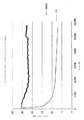
図2は図1に類似するが、炭素に対する活性材料の比(体積比)対空隙率の領域を規定する特定の炭素マトリックス体積分率によって特徴付けられる線も示す。C=2%で示す線a1は、x軸空隙率値98%から傾き−1/0.02で延び、C=30%で示す線a2は、x軸空隙率値70%から傾き−1/0.3で延びる。フル充電時に体積比に変換された場合に空隙率および導電性繊維の質量に対する鉛の質量充填比を有する本発明の実施形態の電極は、線a1およびa2間の領域中の点を規定する。
FIG. 2 is similar to FIG. 1 but also shows a line characterized by a specific carbon matrix volume fraction which defines the area of the ratio of active material to carbon (volume ratio) to porosity. The line a1 shown at C = 2% extends from the x-axis porosity value 98% with a slope of -1 / 0.02, the line a2 shown at C = 30% has a slope -1 / 1 / from the
C=3%で示す線b1は、x軸空隙率値97%から傾き−1/0.03で延び、C=20%で示す線b2は、x軸空隙率値80%から傾き−1/0.2で延びる。フル充電時に体積比に変換された場合に空隙率および導電性繊維の質量に対する鉛の質量充填比を有する本発明の実施形態の電極は、線a1およびa2間の領域中の点を規定する。 The line b1 shown at C = 3% extends from the x-axis porosity value 97% to an inclination -1 / 0.03 and the line b2 shown at C = 20% extends from the x-axis porosity value 80% to an inclination -1 / It extends by 0.2. The electrode of the embodiment of the present invention having a porosity and a mass loading ratio of lead to mass of conductive fiber when converted to volume ratio at full charge defines a point in the region between the lines a1 and a2.
C=4%で示す線c1は、x軸空隙率値96%から傾き−1/0.04で延び、C=15%で示す線c2は、x軸空隙率値85%から傾き−1/0.15で示す。フル充電時に体積比に変換された場合に空隙率および導電性繊維の質量に対する鉛の質量充填比を有する本発明のより好適な実施形態の電極は、線a1およびa2間の領域中の点を規定する。詳細には、このような電極を用いて、改善されたまたは比較的高いDCAおよびCCA双方を備えたセルおよび/または電池を形成することができ、また、ハイブリッド車両における用途に特に適した低水消費を持ち得る。 The line c1 shown at C = 4% extends from the x-axis porosity value 96% to a slope −1 / 0.04 and the line c2 shown at C = 15% extends from the x-axis porosity value 85% to the slope −1/1 It shows by 0.15. An electrode of a more preferred embodiment of the present invention having a porosity and a mass loading ratio of lead to mass of conductive fiber when converted to volume ratio at full charge is a point in the region between lines a1 and a2 Specify. In particular, such electrodes can be used to form cells and / or batteries with both improved or relatively high DCA and CCA, and low water, which is particularly suitable for use in hybrid vehicles. It can have consumption.
線a1およびa2、b1およびb2、ならびにc1およびc2の傾きは、空隙率ならびに鉛体積の導電性繊維体積に対する比に関連する式によって記述される。

サイクル性能は、多数のサイクルの後のPb粒子およびPbSO4粒子の適切な小型粒径の維持に依存し得る。このような小型粒径にすることにより、粒子が電流生成反応を媒介する炭素繊維表面の近隣に存在する場合にPbSO4またはPbがPb++に分解して必要な速度および電流を得るための十分な表面積が得られる。多数のサイクル後の粒径は、導電性繊維間の繊維間間隔サイズに近密に近隣し得るため、両者間に粒子が近密に配置される。よって、より小さな直径の導電性繊維を同じ全体的体積繊維部分に設けることにより、繊維間の隙間も相応に小さくなり、活性粒子も相応に小さくなる。よって、より小さな繊維でより大きな表面積およびより高い速度を達成することが可能になる。 The cycling performance may depend on maintaining the proper small particle size of the Pb and PbSO 4 particles after a number of cycles. Such a small particle size is sufficient for PbSO 4 or Pb to be decomposed into Pb ++ to obtain the necessary speed and current when the particles are present in the vicinity of the carbon fiber surface that mediates the current generation reaction. Surface area is obtained. Because the particle size after multiple cycles can be closely adjacent to the inter-fiber spacing size between the conductive fibers, the particles are closely spaced between the two. Thus, by providing smaller diameter conductive fibers in the same overall volume fiber portion, the gaps between the fibers will be correspondingly smaller and the active particles will be correspondingly smaller. Thus, it is possible to achieve greater surface area and higher velocity with smaller fibers.
導電性繊維の直径に対する粒径の比に関連して、電極サイクル時における粒径変化は大きいため、最終粒径は、開始サイズから若干独立する。しかし、開始サイズは、繊維間に容易にはまることができるように十分に小さく選択する必要がある(例えば、7または8ミクロンの直径の繊維の場合に約10ミクロン未満)。充電時における周囲のPbSO4粒子上の各炭素繊維による浸食作用により、多数のサイクルにわたる炭素繊維の成長が抑制されることが予測される。よって、「硫酸化」の低減および回避が可能になり、長期サイクル寿命が得られる。 The final particle size is somewhat independent of the starting size, as the particle size change during the electrode cycle is large, in relation to the ratio of particle size to diameter of the conductive fibers. However, the starting size should be chosen small enough to be able to fit easily between the fibers (eg, less than about 10 microns for 7 or 8 micron diameter fibers). The erosion by each carbon fiber on the surrounding PbSO 4 particles during charging is expected to suppress the growth of carbon fiber over many cycles. Thus, "sulfation" can be reduced and avoided, and a long cycle life can be obtained.
上記の導電性繊維材料は、(交差する縦横繊維を含む)織物材料、ニット材料、または不織材料(例えば、フェルト材料)であり得る。電流収集器材料のバルク抵抗率の好適には10Ωmm未満であり、好適には1Ωmmまたは0.1Ωmm未満である。この材料は、炭素繊維材料を含み得る(例えば、織物またはニットまたは不織またはフェルト炭素繊維織物)。繊維の絡み合いおよび交差がランダムである不織材料を用いた場合、縦横繊維が直角で規則的に交差する織物材料よりも有利であり得る。 The conductive fiber material described above can be a woven material (including intersecting longitudinal and lateral fibers), a knit material, or a non-woven material (eg, a felt material). The bulk resistivity of the current collector material is preferably less than 10 ohm mm, preferably less than 1 ohm mm or 0.1 ohm mm. The material may comprise a carbon fiber material (e.g. woven or knit or non-woven or felt carbon fiber woven). The use of non-woven materials in which the entanglement and intersection of the fibers is random may be advantageous over textile materials in which the longitudinal and transverse fibers regularly intersect at right angles.
適切な炭素繊維材料は、レーヨン、ポリアクリロニトリル、フェノール樹脂またはピッチ材料を含み得るかまたはこのような材料から導出され得る。 Suitable carbon fiber materials may include or be derived from rayon, polyacrylonitrile, phenolic resins or pitch materials.
典型的には、導電性繊維材料は、材料の主要面における長さおよび幅寸法を有し、材料の主要面に垂直な平均厚さは、例えば約0.2mmまたは約1mmであり得かつ/または5mm未満または3mm未満または2mm未満であり得る。 Typically, the conductive fiber material has a length and a width dimension in the major surface of the material, and the average thickness perpendicular to the major surface of the material can be, for example, about 0.2 mm or about 1 mm and / Or it may be less than 5 mm or less than 3 mm or less than 2 mm.
少なくとも一部の実施形態において、導電性繊維材料の導電性繊維間の平均間隔は、平均繊維径の約0.5〜約10倍または約1〜約5倍であり、あるいは約20ミクロン未満、または約10ミクロン未満であり、平均導電性繊維径は約10ミクロン未満である。 In at least some embodiments, the average spacing between conductive fibers of the conductive fiber material is about 0.5 to about 10 times or about 1 to about 5 times the average fiber diameter, or less than about 20 microns, Or less than about 10 microns, and the average conductive fiber diameter is less than about 10 microns.
フェルトまたは他の不織平面電極材料は、より厚い材料を面分断することにより、極めて薄く(例えば、例えば2.5mm以下)作製することができる。すなわち、材料を1回以上面切断して、より厚い不織材料を分断して、類似の長さおよび幅の複数のシートを得つつ、開始シートの厚さを低減する。これを図7中に模式的に示す。図7に示す微細切断刃60は、駆動ローラー61,62の周囲を連続的に平面内において通過しかつ駆動ローラー61,62によって駆動され、その結果、ベッド64上の炭素フェルトシート63がスライスされて、同一の長さおよび幅でありかつ厚さが半分の2枚の炭素フェルトシートが形成される。各得られた炭素シートをさらに面分断することができる。
Felts or other non-woven planar electrode materials can be made very thin (e.g., for example 2.5 mm or less) by sectioning thicker materials. That is, the material is face cut one or more times to break up the thicker nonwoven material to reduce the thickness of the starting sheet while obtaining multiple sheets of similar length and width. This is schematically shown in FIG . The
織物炭素繊維材料は、「牽切加工された」炭素繊維トウから織られ得る(すなわち、製造後により多数の連続的炭素繊維フィラメントのトウ(束))を牽引して、個々の連続するフィラメントを切断してより短いフィラメントとし、フィラメントの端部を各切断部において長さ方向に分離することにより、炭素繊維トウのフィラメント本数を低減する効果が得られる。その結果得られた低下したフィラメント本数トウを(ロープのように)捻って、トウの完全性を維持する。例えば、50,000本の連続するフィラメントのトウに牽切加工を行うことにより、例えば600本のより短い個々のフィラメントによって構成されたより長尺のトウを生成することができる。その後、これら600本のより短い個々のフィラメントが捻られる。 Woven carbon fiber materials can be woven from "cut-off" carbon fiber tows (ie, tow more bundles of continuous carbon fiber filaments after manufacture) to produce individual continuous filaments The effect of reducing the number of filaments of carbon fiber tow can be obtained by cutting into shorter filaments and separating the ends of the filaments in the lengthwise direction at each cut. The resulting reduced number of filamentous tows are twisted (like a rope) to maintain tow integrity. For example, by draining a tow of 50,000 continuous filaments, a longer tow composed of, for example, 600 shorter individual filaments can be produced. The 600 shorter individual filaments are then twisted.
少なくとも一部の実施形態において、導電性繊維材料は、平均長さが3〜50mmの範囲であるフィラメントを含む。 In at least some embodiments, the conductive fiber material comprises filaments having an average length in the range of 3 to 50 mm.
セルまたは電池の1以上の陰極、1以上の陽極あるいはこの両方を上記のように形成することができる。 One or more cathodes of the cell or battery, one or more anodes, or both may be formed as described above.
好適な実施形態において、導電性の電流収集材料繊維は、本質的に導電性である。好適な実施形態において、電極繊維は炭素繊維である。しかし、一部の実施形態では、炭素繊維材料を導電性を増加させるように処理することも可能である。他の実施形態において、電極繊維は、導電性の低い微小材料であり得、その繊維を導電性コーティングまたはより高い導電性のコーティングでコーティングする。一部の実施形態において、電流収集器材料の繊維が、Pb材料またはPb材料でコーティングされ得る。例えば、陰極または電極をPbでコーティングすることができ、陽極をPbでコーティングした後、その上にPbO2をコーティングすることができる。 In a preferred embodiment, the conductive current collection material fibers are inherently conductive. In a preferred embodiment, the electrode fibers are carbon fibers. However, in some embodiments, carbon fiber materials can also be treated to increase conductivity. In other embodiments, the electrode fibers can be micromaterials of low conductivity, which are coated with a conductive coating or a higher conductivity coating. In some embodiments, fibers of the current collector material may be coated with Pb material or Pb material. For example, the cathode or electrode can be coated with Pb, and after the anode is coated with Pb, PbO 2 can be coated thereon.
好適には、電流収集器材料およびその繊維は可撓性であり、これにより、電流収集器材料へ取り付けられた活性材料の電池サイクル時における体積変化への対応が支援され、微小繊維による活性材料の補強も得られ、双方特性により、使用されている電極からの活性材料の離脱(「脱落」)の低減が支援される。 Preferably, the current collector material and its fibers are flexible, thereby helping to cope with volume changes during cell cycling of the active material attached to the current collector material, and the active material by means of fibrils Reinforcement is also obtained, both properties helping to reduce the removal ("dropping") of the active material from the electrode being used.
一部の実施形態において、導電性繊維材料は、電極または各電極の単一の電流収集器を含む。 In some embodiments, the conductive fiber material comprises an electrode or a single current collector of each electrode.
あるいは、電極または各電極は、炭素繊維の導電性繊維材料に加えて、同様に電流収集器としての金属格子を含み得る。好適な実施形態において、導電性繊維材料は炭素繊維材料を含み、金属格子は鉛格子を含む。炭素繊維層を金属格子へ導電的に接続することにより、格子が炭素繊維層からの電流を受容し、電極を外的に接続する。 Alternatively, the or each electrode may, in addition to the carbon fiber conductive fiber material, also comprise a metal grid as current collector. In a preferred embodiment, the conductive fiber material comprises a carbon fiber material and the metal grid comprises a lead grid. By conductively connecting the carbon fiber layer to the metal grid, the grid receives the current from the carbon fiber layer and connects the electrodes externally.
各セルの陰極または陽極または両極は、金属格子を含み得る。 The cathode or anode or both electrodes of each cell may comprise a metal grid.
電極が金属格子を含む場合、好適には電流を生成するアクティブマスの少なくとも20%を導電性繊維材料を通じて分散させる。好適な実施形態において、少なくとも40%、50%、80%、または80%を超えるアクティブマスを導電性繊維材料中に分散させる。よって、80%、60%、50%または20%未満のアクティブマスを金属格子中に(詳細には、アパチャ内に)分散させることができる。 If the electrode comprises a metal grid, preferably at least 20% of the active mass generating the current is dispersed through the conductive fiber material. In preferred embodiments, at least 40%, 50%, 80%, or more than 80% of the active mass is dispersed in the conductive fiber material. Thus, less than 80%, 60%, 50% or 20% of the active mass can be dispersed in the metal grid (in particular in the aperture).
一部の実施形態において、20%以上40%以下のアクティブマスを導電性繊維材料を通じて分散させる。 In some embodiments, 20% or more and 40% or less of the active mass is dispersed through the conductive fiber material.
好適な実施形態において、導電性繊維材料は、金属格子のいずれかの側上に1つ以上が設けられた複数の層として存在する。あるいは、導電性繊維材料は、金属格子の片側上の単一の層として存在する。 In a preferred embodiment, the conductive fiber material is present as a plurality of layers provided one or more on either side of the metal grid. Alternatively, the conductive fiber material is present as a single layer on one side of the metal grid.
金属格子は、特に主要面において導電性繊維材料成分と類似する表面積または類似の高さおよび幅寸法を持ち得るが、別の実施形態において、金属格子は、より小さな寸法(例えば、より小さな高さおよび幅寸法)を持ち得、いずれかの側上の2つのより大きな炭素繊維層間において例えばより幅狭鉛ストリップを含み得る。 The metal grids may have surface areas or similar height and width dimensions similar to the conductive fiber material component, particularly in major planes, but in another embodiment, the metal grids have smaller dimensions (eg, smaller heights) And width dimensions) and may include, for example, narrower lead strips in the two larger carbon fiber layers on either side.
典型的には、電池またはセルの構築時において、微小電流収集器材料に圧力下においてペーストを含浸させる。このペーストは、好適な形態において、PbおよびPbOおよび希硫酸のPbおよびPbO粒子の混合物を含む。あるいは、ペーストは、硫酸鉛(PbSO4)粒子および希硫酸を含み得る。一部の実施形態において、ペーストは、電極中への含浸時において、0%〜約5重量%を超えるか、または0.25重量%〜約3重量%または0重量%〜約2重量%または0.5〜2.5重量%の硫酸ペーストを含む希硫酸を含む。Pb粒子は、繊維間の空間に容易に入り込むことが可能な小型の10ミクロン以下のサイズの粉砕された粒子または化学的に形成された粒子を含み得る。 Typically, during battery or cell construction, the microcurrent collector material is impregnated with paste under pressure. The paste comprises, in a preferred form, a mixture of Pb and PbO and Pb and PbO particles of dilute sulfuric acid. Alternatively, the paste may include lead sulfate (PbSO 4) particles and dilute sulfuric acid. In some embodiments, the paste is 0% to greater than about 5% by weight, or 0.25% to about 3% by weight or 0% to about 2% by weight at the time of impregnation into the electrode. It contains dilute sulfuric acid containing 0.5 to 2.5% by weight of sulfuric acid paste. The Pb particles may comprise small sub-10 micron sized crushed or chemically formed particles that can easily enter the spaces between the fibers.
このペーストは、任意選択的に他の添加剤も含み得る(例えば、カーボンブラック、硫酸バリウムおよび/または膨張剤(例えば、リグノスルホネート)。硫酸バリウムは、硫酸鉛結晶化のための種晶として機能するため、鉛間の硫酸反応が促進される。膨張剤により、負プレートにおける硫酸粒子の凝集(例えば、放電時における鉛硫酸の固体質量の形成)の回避が支援される。 This paste may optionally also contain other additives, such as carbon black, barium sulfate and / or swelling agents (e.g. lignosulfonates) Barium sulfate functions as a seed for lead sulfate crystallization In order to promote the sulfuric acid reaction between the lead, the expansion agent helps to avoid the aggregation of sulfuric acid particles on the negative plate (eg, the formation of a solid mass of lead sulfuric acid during discharge).
例えば、膨張剤は、約0.05重量%〜約0.25重量%または約0.09〜0.2重量%または約0.09〜0.17重量%のペーストを含浸時において含み得る。ペースト中に膨張剤化合物を含めた場合、CCA性能には良い影響が得られるものの、DCA性能に悪影響が出ることが判明している。従来では、濃度が約0.2%以上である膨張剤をペーストへ付加していた。約0.09重量%〜約0.15重量%の膨張剤濃度でペーストを含浸時において含めると、良好なDCAおよびCCA性能双方を達成できることが判明している。 For example, the expansion agent may comprise about 0.05 wt% to about 0.25 wt%, or about 0.09 to 0.2 wt%, or about 0.09 to 0.17 wt% paste at the time of impregnation. It has been found that the inclusion of an expander compound in the paste has a positive effect on CCA performance but adversely affects DCA performance. In the past, expansion agents having a concentration of about 0.2% or more were added to the paste. It has been found that both good DCA and CCA performance can be achieved if the paste is included at the time of impregnation with an expanding agent concentration of about 0.09% by weight to about 0.15% by weight.
ペーストはまた、Ag、Bi、Znまたはそのうち任意のものの化合物を抗ガス化剤として含み得る。 The paste may also contain Ag, Bi, Zn or any compound thereof as an anti-gassing agent.
ペーストは、電極材料中への含浸時において比較的低い粘度を持ち得る(例えば、重力下において水平表面上において(流れるのではなく)自身を支持し得る)。好適には、ペーストは、クリームのような堅さを有する。これは、電極中への含浸時においてペーストに(0を超えるが)5重量%未満の重量の硫酸のペーストを含む希釈硫酸が含まれる場合に達成されることが判明している。 The paste can have a relatively low viscosity upon impregnation into the electrode material (eg, it can support itself (rather than flow) on a horizontal surface under gravity). Preferably, the paste has a cream-like firmness. It has been found that this is achieved when the paste contains diluted sulfuric acid containing a paste of sulfuric acid ( less than 0) by weight less than 5% by weight at the time of impregnation into the electrode.
ペーストによる電極材料の含浸を支援するために、低周波数振動(例えば、2kHz未満または1kHz未満または50〜500Hzの振動)をペーストまたは電極材料または双方へ付加することができる。混合時におけるペーストの振動による混合を支援するためにPb粒子、硫酸および水を混合してペーストを形成した場合、有用であることも判明している。 Low frequency vibrations (e.g. less than 2 kHz or less than 1 kHz or 50 to 500 Hz vibrations) can be applied to the paste or electrode material or both to assist in the impregnation of the electrode material with the paste. It has also been found to be useful when the paste is formed by mixing Pb particles, sulfuric acid and water to assist in the vibratory mixing of the paste during mixing.
セルまたは電池構造後の初期のセル形成(活性粒子結合が形成される第1の充電および放電サイクル)時において、先ず導電性骨格を構築することにより、セル形成が発生する。この導電性骨格は、負活性材料中のPbの大部分を占有し、通常は数ミリメートルの長さにわたって構築されて(恐らくは千個および/千個以上の微小粒子のストリングを端部で接続する)。この段階において、小型のPbSO4粒子も生成される。第2に、これらのより小さな粒子がこの導電性骨格へ付着することにより、電流の提供および受容が行われる。本発明によれば、Pb格子は、微小繊維電流収集器によって交換または補完され、ペーストは、PbSO4またはPbOまたはPb粒子(または他の粒子ofPb化合物)を含むため、形成時において実質的にこれらのPb含有粒子のうちPbを微小導電性電流収集器材料中の最も近隣の繊維へ付着させるだけでよい。このような構成は、形成時において充電電流が定期的にパルスされる点において有用であり得る。 During initial cell formation (first charge and discharge cycles where active particle bonding is formed) after cell or battery construction, cell formation occurs by first constructing the conductive framework. This conductive framework occupies most of the Pb in the negative active material and is usually built over a few millimeters in length (possibly connecting a string of one thousand and / or more than a thousand microparticles) ). Small PbSO 4 particles are also produced at this stage. Second, the attachment of these smaller particles to the conductive scaffold provides for the acceptance and delivery of current. According to the invention, the Pb lattice is replaced or complemented by a fibril current collector, and the paste contains PbSO 4 or PbO or Pb particles (or other particles of Pb compounds) so that they are substantially formed as they are formed. Of the Pb-containing particles of the present invention, it is only necessary to attach Pb to the closest fibers in the microconductive current collector material. Such an arrangement may be useful in that the charging current is periodically pulsed during formation.
繊維電流収集器材料は、機械的に支持され得、支持用の機械的フレームにより、各電極からセルまたは電池端子への電気的接続も可能になる(外部電極接続)。例えば、全側部上のまたは2つの対向する側部上の対向する金属フレーム要素間の周辺の金属フレームにより、電流収集器材料の1つ以上の四角形または矩形の隣接層を支持することができる。あるいは、例えば、各セルの同心の円筒型の正プレートおよび負プレートは、いずれかの円筒型端部において円形金属フレームによって支持された、微小電流収集器の円筒型部分を含み得る。一般的に、全ての形態の外部コネクタは、本明細書中において「突起」と呼ばれる。 The fiber current collector material can be mechanically supported and the mechanical frame for support also allows electrical connection from each electrode to the cell or battery terminals (external electrode connection). For example, the surrounding metal frame between opposing metal frame elements on all sides or on two opposite sides can support one or more square or rectangular adjacent layers of current collector material . Alternatively, for example, the concentric cylindrical positive and negative plates of each cell may comprise the cylindrical portion of a micro-current collector supported by a circular metal frame at either cylindrical end. Generally, all forms of external connectors are referred to herein as "protrusions."
図3aは、織物炭素繊維電極50の模式図であり、炭素繊維材料上に形成された電極の圧力ダイカストによる外部接続のための金属突起51が設けられている。図3bは、タブが付加された53を備えた別の形状の突起を示す。図3cは、突起を含む炭素繊維材料の複数の層の断面を示す。この突起は、金属によって形成される(例えば、PbまたはPb合金(本明細書中において双方を包含的にPbと呼ぶ)が、(好適には繊維材料中への挿入および/または繊維材料間への挿入によって電気的に接続する)別の材料によって形成してもよい。好適には、突起は、電極の縁部に沿って実質的に全体的に延びる。例えば、電極が四角形または矩形形状である場合、突起は、電極の一縁の長さ全体にわたって実質的に延びる。好適には、突起は、電極材料そのものよりも実質的により肉厚ではない。
FIG. 3a is a schematic view of a woven
一部の実施形態において、電極材料のフィラメント/繊維のうち実質的に全てまたは少なくとも大部分は、繊維の双方の端部または少なくとも一端が電気的に接続された金属フレームまたはフレーム要素間または金属フレームまたはフレーム要素への電極にわたって連続的に延びる。連続繊維の織物織物が最適であり得る。 In some embodiments, substantially all or at least a majority of the filaments / fibers of the electrode material are between metal frames or frame elements or metal frames to which both ends or at least one end of the fibers are electrically connected Or extend continuously over the electrodes to the frame element. Continuous fiber woven fabrics may be optimal.
炭素繊維と突起または導電性フレームとの間の電気接続は、最小抵抗結合である必要があり、好適な形態において、各繊維端部は、(電池またはセル構築時において繊維端部を金属フレームを物理的に固定しかつ電気的に接続する)溶融金属によって包囲される。金属フレームまたはフレーム要素そのものは、溶融金属ストリップを電極材料の1つ以上の縁部に沿って冷却して繊維端部を包囲および埋設することにより、形成することができる。任意選択的に、繊維または織物は、1つ以上の縁部において1つ以上のフレーム要素を超えて延び得、これにより、別の隣接する電極または電極部分が形成される。好適には、電極繊維のうち実質的に全てまたは少なくとも大部分は、1方向または材料の軸と同一麺において、活性材料中において繊維が開始する地点から100mm〜10以下距離においてまたは材料の対向する縁部双方において、金属フレーム要素へ電気的に接続される。この距離または各電流収集器材料部分のサイズまたは面積は、ほとんどの導電方向における電流収集器材料のバルク抵抗率によって主に決定される。織物の1つの縁部のみが金属フレーム要素へ電気的に接続される場合、好適には織物中のこのほとんどの導電方向を接続された縁部に対して垂直にアライメントさせることにより、全体的抵抗を最小化させる。顕著な容量損失無く電極中の電流密度を最大にするために、接続縁部からの織物の長さを約50〜100mmまでにすることができる。あるいは、金属フレームにおいてアパチャを含む金属シートを材料の片側または両側上に設けてもよく、その場合、電流搬送および搬送する活性材料からの電流収集を行う炭素繊維のみと共にアパチャまたは窓部が残る。例えば、高さ200mmの電極フレームは、高さがそれぞれ100mmである2つの窓部を含み得、導電性ウェブが縁部の周囲に設けられることにより、任意のクロスバーから最も遠い距離は50mmとなる。これらの窓領域それぞれについて、炭素織物を金属クロスバー内および縁部内において分散させ、取り付けることができる。 The electrical connection between the carbon fibers and the protrusions or conductive frame should be a minimum resistance bond, and in the preferred form, each fiber end (when the battery or cell is constructed, the fiber end is a metal frame It is surrounded by molten metal (physically fixed and electrically connected). The metal frame or frame element itself can be formed by cooling the molten metal strip along one or more edges of the electrode material to surround and embed the fiber ends. Optionally, the fibers or fabrics can extend beyond one or more frame elements at one or more edges, thereby forming another adjacent electrode or electrode portion. Preferably, substantially all or at least a majority of the electrode fibers are in one direction or in the same noodle as the axis of the material, at a distance of 100 mm to 10 mm or less from the point where the fibers start in the active material Both edges are electrically connected to the metal frame element. The distance or size or area of each current collector material portion is mainly determined by the bulk resistivity of the current collector material in most conduction directions. If only one edge of the fabric is electrically connected to the metal frame element, the overall resistance is preferably achieved by aligning most of the conductive directions in the fabric perpendicularly to the connected edge. Minimize The fabric length from the connecting edge can be up to about 50 to 100 mm in order to maximize the current density in the electrode without noticeable capacity loss. Alternatively, a metal sheet containing apertures in the metal frame may be provided on one or both sides of the material, in which case the apertures or windows remain with only carbon fibers that carry current from the active material being transported and transported. For example, an electrode frame with a height of 200 mm may include two windows, each 100 mm in height, with the conductive web being provided around the edge so that the distance from any crossbar is 50 mm Become. For each of these window areas, the carbon fabric can be dispersed and attached in the metal crossbar and in the edge.
図4は、片側からの電極55の模式図であり、図3と同様に金属突起56が一縁部に沿って設けられる。この実施形態において、炭素繊維材料の片側または両側上の電極は、金属ワイヤまたはテープ57を含む。金属ワイヤまたはテープ57は、電極材料55および突起56へ電気的に導電的に取り付けられて、電極の炭素繊維材料そのものを通じた微小経路に加えて、さらなるマクロスケール電流収集経路を炭素繊維から金属突起56へと提供する。金属ワイヤまたはテープの電極材料への取り付けは、例えば電解質中において溶解しない糸または電流収集器を所定位置に保持する他の不活性の鉛蓄電池結合材料(例えば、樹脂、セメントまたは埋め込み用ミックス)を縫合することにより、行われる。金属ワイヤまたはテープは、製造時において電極材料中へ押圧され得る。あるいは、ワイヤまたはテープなどを、炭素繊維電極材料上に半田付けまたは印刷してもよい。金属ワイヤまたはテープは、図示のように炭素繊維材料片側または両側上に波状に配置することができ、電極の一縁部において突起56間を連続的に延びる。電極の一縁部において、ワイヤまたはテープが、図示のように別の間隔を空けて配置された縁部の電極においてまたは上記電極に向かって突起中に埋設されることにより、突起56へ導電的に接続される。あるいは、ワイヤまたはテープは、電極の対向する縁部または電極周囲のフレームに沿った金属突起間に延びてもよい。あるいは、ここでも、別個の長さのワイヤまたはテープが一縁部における突起から電極の別の縁部へ向けて延びてもよいし、あるいは、ここでも、記載のようなワイヤまたはテープマクロ導体は、炭素繊維材料の片側または両側上に取り付けられた金属メッシュを含んでもよい。
FIG. 4 is a schematic view of the
図5は電極55の断面図であり、金属ワイヤまたはテープ56が電極材料の片側に取り付けられている。図6は、炭素繊維材料の2つの層55aおよび55bによって構成された電極の断面図であり、金属ワイヤまたはテープ56が両者間に埋設または挟設されている。金属ワイヤまたはテープを挟設した炭素繊維は、製造時において共に圧縮することができる。
FIG. 5 is a cross-sectional view of
銅によって形成されている場合、鉛またはチタンまたはPb酸環境内において不活性である他の金属によるコーティングを例えば溶融めっき、押し出しまたは電気めっきによって施すことにより、ワイヤまたはテープまたはメッシュまたは任意の露出端部を含む類似のものをセル内の酸化から保護する必要がある。ワイヤまたはテープまたはメッシュの端部は終端し得、突起または周辺のフレーム中へ埋設され得る。電流収集器が陰極として機能する電極の外面上にある場合、電流収集器を陽極からの陽極酸化から保護することが重要である。 A wire or tape or mesh or any exposed end, for example by applying a coating with lead or titanium or another metal which is inert in a Pb-acid environment, for example by hot-dip plating, extrusion or electroplating if formed by copper It is necessary to protect similar ones, including parts, from oxidation in the cell. The ends of the wire or tape or mesh may terminate and may be embedded in the projections or surrounding frame. When the current collector is on the outer surface of the electrode that functions as the cathode, it is important to protect the current collector from anodic oxidation from the anode.
好適には、ワイヤまたはテープは、電極の長さの上方および下方において電極幅にわたる均等間隔で延び、図3中に示すように交差点は全く無く、これにより、局所的ホットスポットの発生または特定領域内の熱蓄積が回避され、均等な電流収集が電極上において行われる。 Preferably, the wires or tapes extend at equal intervals across the electrode width above and below the length of the electrode and there are no cross points at all as shown in FIG. 3, thereby causing localized hot spots or specific areas Internal heat buildup is avoided and equal current collection is performed on the electrodes.
好適には、ワイヤまたはテープまたはメッシュまたは類似のマクロスケール電流収集システムの体積は、電極の体積の約15%未満である(突起または周囲の金属フレームなどは除く)。 Preferably, the volume of the wire or tape or mesh or similar macroscale current collection system is less than about 15% of the volume of the electrode (except for protrusions or surrounding metal frame etc).
一部の実施形態において、本発明の電極は、コンポジット型(金属格子も含むもの)であれ非コンポジット型(金属格子を含まないもの)であれ、(長さおよび幅にわたるかまたは電極と同一平面内の寸法の)厚さは、電極の任意の面内寸法の多数倍よりも小さい(例えば、10、20、50、または100倍)。電極厚さは、例えば5mm未満または3mm未満であり得る。電極の面内長さおよび幅寸法はそれぞれ、例えば50または100mmを超え得る。このような電極は、肉薄の平面形態を持ち得る。本発明の1つの形態のコンポジット電極は、厚さ約3.5mm以下(例えば、厚さ約0.5mm)の金属格子を含み得、厚さ約2mm以下(例えば、厚さ約0.3mm)の炭素繊維層をいずれかの側上に含む。 In some embodiments, the electrodes of the present invention, whether composite (including metal grids) or non-composite (not including metal grids), (over the length and width or flush with the electrodes The inner dimension) thickness is smaller (e.g. 10, 20, 50 or 100 times) than any in-plane dimension of the electrode. The electrode thickness may be, for example, less than 5 mm or less than 3 mm. The in-plane length and width dimensions of the electrodes may each exceed, for example, 50 or 100 mm. Such an electrode may have a thin planar form. One form of the composite electrode of the present invention may comprise a metal grid of about 3.5 mm or less in thickness (eg, about 0.5 mm in thickness) and about 2 mm or less in thickness (eg, about 0.3 mm in thickness) Of carbon fiber on either side.
好適な形態において、電極は、略平坦状であり、電極の少なくとも1つの縁部に沿った外部接続のための金属突起からの寸法は、例えば100mm未満または70mm未満または50mm未満または約30mm以下である(マクロスケール電流収集器を含むかまたは含まない)。あるいは、このような平面形態を例えば円筒型の電極として形成してもよい。 In a preferred form, the electrode is substantially flat and the dimensions from the metal projection for external connection along at least one edge of the electrode are, for example, less than 100 mm or less than 70 mm or less than 50 mm or less than about 30 mm Yes (with or without macro-scale current collector). Alternatively, such a planar configuration may be formed, for example, as a cylindrical electrode.
電極電流収集器材料として用いられる炭素繊維材料は、熱処理され得る。熱処理を行うことにより、材料の熱伝導率も増加するため、使用時における電極上の局所的ホットスポットを回避するのに十分である。炭素繊維は一般的には炭化水素であり、製造時において約1100℃以上まで加熱される(「炭化」)。炭素繊維材料を本発明の電池またはセル中の電流収集器材料として用いるために、炭素繊維材料を2200〜2800℃においてさらに加熱することにより、既に芳香族または黒鉛となっている炭素中の領域を拡大することができ、電気伝導度の向上につながる。電気および/または熱伝導率を向上させるための熱処理は、例えば抵抗加熱された炉内において行わってもよいし、あるいは電気アーク放電によって行ってもよい。電気アーク放電の場合、加えて、炭素繊維からの非黒鉛炭素の大部分または一部と、黒鉛炭素の極一部のみとを蒸散させることができる。 Carbon fiber materials used as electrode current collector materials can be heat treated. The thermal treatment also increases the thermal conductivity of the material, which is sufficient to avoid localized hot spots on the electrode during use. Carbon fibers are generally hydrocarbons and are heated to about 1100 ° C. or higher at the time of production ("carbonization"). Further heating of the carbon fiber material at 2200 ° -2800 ° C. to use the carbon fiber material as a current collector material in the battery or cell of the present invention results in areas in the carbon that are already aromatic or graphite. It can be expanded, leading to an improvement in electrical conductivity. The heat treatment to improve the electrical and / or thermal conductivity may, for example, be carried out in a resistively heated furnace or by means of an electric arc discharge. In the case of an electric arc discharge, additionally, it is possible to evaporate most or part of non-graphitic carbon from carbon fibers and only a small part of graphitic carbon.
炭素繊維電流収集器の材料に対して十分な温度まで熱処理を行うことにより、電気伝導度を増加させることができる。熱処理は、電気アーク放電によって行われ得る。特定の実施形態において、2つの電極間の隙間内の電気アークを通じてまたは電極を通過させて反応室内において炭素繊維材料を移動させることによ、炭素繊維材料をアーク放電によって処理することができ、これにより、材料の活性化に有効な温度において電極と材料との間に電気アークが存在する。図8において、参照符号1によって示すリアクター室において、放電アークが生成される。電極2および3は、リアクター室1内に突出し、典型的には当該分野において公知のような電極供給機構4によって取り付けられる。これにより、陽極であり得る電極3の位置と、陰極であり得る電極2(陽極および陰極の位置は逆転可能である)とを調節してアークを生成することができ、動作時においてアークを維持または(必要ならば)調節することができる。電極の冷却のために、銅管コイルからなる冷却システム5によって各電極を包囲して、この冷却システム5を通じて水を循環させてもよい。リアクターの動作時において、炭素繊維材料8は、電極2および3間およびアーク中を図示のように通過する。この様子を図9中により詳細に示す。電流は、非黒鉛炭素を蒸発させかつ破壊的な局所的アーク発生モードを誘発しないような十分な電流とすべきである。10A〜20Aの動作が推奨される。材料は、リアクター室中のスリット12を通じてリアクター室に進入し得、リアクター室中の電極の他方側上の類似の出口スリット13を通じて退出し得る。リアクター室を通じて材料を供給するための機構が提供される。例えば、リアクターの動作時において、ギアボックスによって駆動されるスプール9から基板をほどくことができる。このギアボックスは、適切な制御システムにより、電動機へと接続される。動作時において、リアクターの内部は好適には、大気圧であるかまたは大気圧を若干上回り、スリット13を通じてリアクターから退出したガス流れがドラフトまたはフィルタなどを介して抽出される。例えば(リアクターのベースにおける開口部11のうちの1つを通じて)制御されたガス流れを反応室1内に導入することにより、不活性ガス(例えば、窒素、アルゴンまたはヘリウム)を例えば反応室を通じてフラッシュすることができる。陽極と、テープを駆動するスプールとを接地すると好適である。基板がリアクター室を通過した後に基板を収集するための任意の取り込み機構も設置すると好適であり、リアクターシェルも同様である。図9を参照して、1つの電極(図中では陽極3)を基板8上に衝突するように配置すると好適であり、これにより、模式的に示すように、基板の移動時において電極に対して基板に張力が付加される。電気アーク放電により、非黒鉛炭素の大部分と、炭素繊維材料の黒鉛炭素のうち極一部のみとを蒸発させることができる。この方法は、導入された金属添加剤(例えば、Pb添加剤)の存在下において実行することができる。
Electrical conductivity can be increased by heat treating the carbon fiber current collector material to a sufficient temperature. Heat treatment may be performed by electric arc discharge. In certain embodiments, the carbon fiber material can be treated by arc discharge by moving the carbon fiber material through the electric arc in the gap between the two electrodes or by passing the electrodes through the reaction chamber, Thus, there is an electric arc between the electrode and the material at a temperature effective to activate the material. In the reactor chamber indicated by
内部の細孔表面積を含む本発明に係る微小電極により、電気化学的貢献を超える電荷受容性を付加するための十分なキャパシタンスが得られる。酸電解質によって十分に湿潤されかつ酸電解質から接近することが可能な電極により、鉛蓄電池の陰極中の従来の活性材料の全体的表面積によって得られるキャパシタンスよりもより大きなキャパシタンスを超える貢献が得られる。これは、数秒間の高電流の吸収または送達を行うための十分な電解二重層容量を持ち得る。あるいは、本発明の電池は、別個の大表面積の電極を含み得る。この大表面積の電極は、上記または各負または正セル電極と平行して、キャパシタンスの増減のために本明細書中に記載のようなアーク処理された炭素繊維材料を含み得る。 The microelectrodes according to the invention comprising internal pore surface area provide sufficient capacitance to add charge acceptance beyond electrochemical contributions. An electrode that is sufficiently wetted by and accessible to the acid electrolyte provides a contribution beyond the capacitance provided by the overall surface area of the conventional active material in the lead-acid battery cathode. It may have sufficient electrolytic double layer capacity to provide high current absorption or delivery for a few seconds. Alternatively, the battery of the invention may comprise separate high surface area electrodes. This high surface area electrode may comprise an arced carbon fiber material as described herein for increasing or decreasing capacitance, in parallel with the or each negative or positive cell electrode.
例えば電気アーク放電による熱処理を行うことにより、細孔表面積の増加およびキャパシタンスの増加を達成することができる。また、Pb(NO3)2溶液を炭素繊維材料上に塗布して乾燥させた後にアーク処理を行うことによっても、(明らかに酸化を通じて)表面積発生を増加させることができる。あるいは、物理的活性化によって材料を活性化してもよい(例えば、約1000℃の温度における蒸気または二酸化炭素)し、あるいは、化学的性化を例えばアルカリ溶液によって行ってもよい。活性化を行うと、典型的にはナノスケールの孔部が生成され、最も典型的には直径50nmまでの孔部が材料中または材料表面上に生成される。約1nmよりも小さな孔部を多く含む材料の場合、導電体としては良くない場合がある。1nm〜約10nmの孔部の場合、大きな容量に必要な表面積は得られるものの、適切な電解質伝導性のための分散イオンの接近を容易にするために、10nmを超えた孔部を分散させる必要も出てくる。また、固体内において十分な電気伝導度も必要となる。 For example, by performing heat treatment by electric arc discharge, an increase in pore surface area and an increase in capacitance can be achieved. Surface area generation can also be increased (obviously through oxidation) by applying a Pb (NO 3 ) 2 solution onto the carbon fiber material and drying followed by arcing. Alternatively, the material may be activated by physical activation (eg, steam or carbon dioxide at a temperature of about 1000 ° C.), or chemical remediation may be performed by, for example, an alkaline solution. Upon activation, typically nanoscale pores are created, most typically pores up to 50 nm in diameter, in or on the material. A material containing many holes smaller than about 1 nm may not be good as a conductor. In the case of pores of 1 nm to about 10 nm, although the surface area required for a large capacity can be obtained, it is necessary to disperse the pores over 10 nm in order to facilitate the access of dispersed ions for appropriate electrolyte conductivity. It also comes out. In addition, sufficient electrical conductivity is also required in the solid.
一部の実施形態において、炭素繊維材料には、炭素ナノチューブ(CNT)が取り付けられる。炭素繊維材料の電気アーク放電処理または触媒の存在下における低温における化学蒸着により、CNT支持材料を生成することができる。 In some embodiments, the carbon fiber material is attached with carbon nanotubes (CNTs). CNT support materials can be produced by electrical arc discharge treatment of carbon fiber materials or chemical vapor deposition at low temperatures in the presence of a catalyst.
上記したように、ハイブリッド車両における用途に適した好適な形態において、本発明の電極構造を含むセルおよび/または電池は、改善されたまたは比較的高いDCAおよびCCA(例えばSAEJ357CCA試験に従って測定されたような、アクシオン試験によって測定されたDCAおよびCCA)双方を持ち得、かつ/または、より多数の充電/放電サイクルと共にDCAまたはより高速のDCAを維持することができ、低い水消費を持つことができ、改善されたまたは比較的高いVEDおよび/または改善された電池寿命を持つことができる。本発明のセルまたは電池の実施形態は、例えば5000または10000サイクル後において、(第1のフル充電時に)開始DCAの少なくとも70%または80%または90%のDCAを維持することができる。本発明のセルまたは電池の実施形態は、アクシオンDCA試験を用いた10,000サイクルにおける充電フェーズごとに、少なくとも0.6または0.7または0.8A/Ahの平均DCAを保持することができる。電池容量は、Amp/時間で測定し、理論最大容量によって除算された実際の電池容量を利用し、本発明のセルまたは電池の実施形態は、利用率を少なくとも55%、60%、70%、または80%以上まで増加することができる。 As noted above, in the preferred form suitable for use in a hybrid vehicle, cells and / or batteries comprising the electrode structure of the present invention may be measured according to the improved or relatively high DCA and CCA (e.g. SAEJ 357 CCA test) Can have both DCA and CCA (measured by the Axion test) and / or maintain DCA or faster DCA with more charge / discharge cycles and have lower water consumption It can have an improved or relatively high VED and / or an improved battery life. Embodiments of the cell or battery of the invention can maintain at least 70% or 80% or 90% DCA of the starting DCA (during the first full charge), for example after 5000 or 10000 cycles. Embodiments of the cell or battery of the present invention can maintain an average DCA of at least 0.6 or 0.7 or 0.8 A / Ah per charge phase in 10,000 cycles using the Axion DCA test. . The battery capacity is measured in Amps / hour and utilizes the actual battery capacity divided by the theoretical maximum capacity, and the cell or battery embodiments of the present invention have at least 55%, 60%, 70% utilization, Or can be increased to 80% or more.
実施例
例示目的のために付与される実験試験の以下の記載において、本発明について説明する。実施例の一部では、DCA試験について言及する。図10に示すDCA試験アルゴリズムに従って、電池システム上におけるストップ/スタートマイクロハイブリッド車両の需要をシミュレートするように設計された高速動的電荷受容性試験(DCAT)を各セルに対して行った。DCAT試験プロファイルは、電池上における加速された破壊寿命試験であり、一定の充電状態において保持され、その結果、DCAT試験を試験システムおよびシステムに関連する較正問題から独立させることができ、これにより、他の寿命試験プロトコルに通常関連する較正問題が回避される。DCAT試験においては、CadexC8000試験システム上におけるアクシオンDCAT試験プロファイルに追従した。試験プロファイルは、以下のステップからなる。
・0.51C放電を60s
・3.15Cパルス放電を1s
・−10s休止(休止終了時において、PDRV(放電後静止電圧)を測定する)
・−PDRVを所与の設定点において保持するように調節された、1.05Cの動的充電期間
・10s休止。
EXAMPLES The invention will be described in the following description of the experimental tests given for the purpose of illustration. Some of the examples refer to DCA testing. According to the DCA test algorithm shown in FIG. 10, a fast dynamic charge acceptance test (DCAT) designed to simulate the demand of a stop / start micro hybrid vehicle on a battery system was performed on each cell. The DCAT test profile is an accelerated destructive life test on the battery and is maintained at a constant state of charge so that the DCAT test can be made independent of the test system and the calibration issues associated with the system, thereby Calibration problems normally associated with other life test protocols are avoided. In the DCAT test, the Axion DCAT test profile on the Cadex C 8000 test system was followed. The test profile consists of the following steps:
・ 60s of 0.51 C discharge
・ 1s 3.15C pulse discharge
-10 s pause (PDRV (stop voltage after discharge measured at the end of pause))
-Dynamic charge period of 1.05 C, adjusted to hold PDRV at a given set point, 10s rest.
この記載のサイクルプロファイルを、典型的な6週間に相当するサイクルカウント30,000まで繰り返す。しかし、この期間は、電池性能によって異なる。5000サイクル毎に、フル充電の後の重放電をによって電極容量を測定した。この試験に合格するためには、セルは、容量を少なくとも2Ahで保持しつつ、DCAT試験を少なくとも30,000回サイクルすることができなければならない。30,000サイクルは、マイクロハイブリッドにおける約3年の電池寿命を示す。 This described cycle profile is repeated to a cycle count of 30,000, which corresponds to a typical six week. However, this period depends on the battery performance. The electrode capacity was measured by heavy discharge after full charge every 5000 cycles. To pass this test, the cell must be able to cycle the DCAT test at least 30,000 times while holding the capacity at least 2 Ah. The 30,000 cycles represent approximately 3 years of battery life in the microhybrid.
実施例1−Pb格子−N371を用いた炭素繊維紙のコンポジット電極
方法:電極を、厚さ3mmであり、体積のうち〜6%までが炭素であり、特定の重量が〜312g/m2でありかつ繊維長さが25mmである炭繊維紙炭素マット(Z−Mat(Zoltek製))から構築した。2つのピースを44mm×70mmの寸法で切断した後、より肉薄の層に分断して、平均厚さが0.26mmの個々の層を生成した。これらの炭繊維層のうち1つを鉛格子の2枚の表面それぞれの上に配置することにより、電極を構築した。
Example 1-Composite electrode of carbon fiber paper using Pb grid-N371 Method: The electrode is 3 mm thick, up to 6% of carbon by volume, with a specific weight of ~ 312 g / m 2 It was constructed from a carbon fiber paper carbon mat (Z-Mat (manufactured by Zoltek)) having a fiber length of 25 mm. The two pieces were cut to dimensions of 44 mm × 70 mm and then cut into thinner layers to produce individual layers with an average thickness of 0.26 mm. An electrode was constructed by placing one of these layers of carbon fiber on each of the two surfaces of the lead grid.
23.2gの酸化鉛(酸化鉛バッチ(2009年にExideから購入))、4.0gの希釈硫酸、調製されたペーストおよび0.187gの硫酸バリウム中において0.10wt%を達成するのに十分なVanisperseAを含む2.7gのVanisperseA(膨張剤)水溶液により、ペーストを調製した。ペーストを超音波槽中において2分間(53kHz周波数、23℃のタンク温度)にわたって混合した。繊維層のうちの1つを平坦プレート上に配置した後、鉛格子を繊維層上に配置した。Pb格子の厚さは2.02mmであり、長さ66.3mmであり、幅44.2mmであり、開口体積分率は〜81.6%であった。表面上にペーストが均等に分配され、全格子ポケットがペーストで充填されるまで、鉛格子表面上にペーストを塗布した。次に、繊維層を部分的に充填するための十分な余分なペーストをペースト塗布された格子表面上に塗布し、その上に第2の炭繊維層を配置した。さらなるペーストを上面上に塗布して、平滑かつ均等な表面を得た。余分なペーストを両面および電極の側部縁部から除去した。ペースト電極の総厚さは、約2.60mmであった。 Sufficient to achieve 0.10 wt% in 23.2 g of lead oxide (lead oxide batch (purchased from Exide in 2009)), 4.0 g of diluted sulfuric acid, the prepared paste and 0.187 g of barium sulfate A paste was prepared with 2.7 g of Vanisperse A (swelling agent) aqueous solution containing Vanisperse A. The paste was mixed in an ultrasonic bath for 2 minutes (53 kHz frequency, 23 ° C. tank temperature). After placing one of the fiber layers on a flat plate, a lead grid was placed on the fiber layer. The thickness of the Pb grating was 2.02 mm, 66.3 mm long, 44.2 mm wide, and the opening volume fraction was ̃81.6%. The paste was applied on the lead grid surface until the paste was evenly distributed on the surface and all grid pockets were filled with paste. Next, sufficient excess paste for partially filling the fiber layer was applied on the pasted grid surface, and the second carbon fiber layer was placed thereon. Additional paste was applied on top to obtain a smooth and even surface. Excess paste was removed from both sides and the side edges of the electrode. The total thickness of the paste electrode was about 2.60 mm.
コンポジット電極中へロードされた湿塊の全体量は24.41gであった。ここで、達成された容量(低電流放電)は、2.695Ahであった(すなわち、理論容量の60%)。格子および繊維層中にペーストが均等に浸透/分散したと仮定すると、19.8%のNAMが電極の繊維層中に分散し、残りは鉛格子中に残留する。電極がフル充電状態時である場合、炭素体積比に対する平均アクティブマスPbは10.03である。炭素繊維間の平均間隔は、約23ミクロンであった。その後、電極の空気乾燥を24時間にわたって大気温度(18℃〜24℃)において行った後、1つの(40%SOC)陽極が各側上にある1.15sgH2SO4の電解質を含むセル内においてペースト電極を組み立てた。このセルを浸漬状態で24時間大気温度(18℃〜24℃)において放置し、セル基準形成を行った。 The total amount of wet mass loaded into the composite electrode was 24.41 g. Here, the capacity achieved (low current discharge) was 2.695 Ah (i.e. 60% of the theoretical capacity). Assuming uniform penetration / dispersion of the paste in the grid and fiber layer, 19.8% of the NAM is dispersed in the fiber layer of the electrode, with the remainder remaining in the lead grid. When the electrode is in a fully charged state, the average active mass Pb to carbon volume ratio is 10.03. The average spacing between carbon fibers was about 23 microns. The electrodes are then air-dried at ambient temperature (18 ° C. to 24 ° C.) for 24 hours, and then in a cell containing 1.15 sg H 2 SO 4 electrolyte, with one (40% SOC) anode on each side. The paste electrode was assembled at. The cell was left immersed for 24 hours at ambient temperature (18 ° C. to 24 ° C.) to form a cell reference.
試験方法および結果:電解質を1.28sgH2SO4で置換し、4サイクルの低電流放電(0.06C)下において安定させた後、高速DCAへ送った。上記したような図11に示すような試験に従って、高速動的電荷受容性試験(HR−DCAT)をセルに行った。結果を以下の表1に示す。 Test Methods and Results: The electrolyte was replaced with 1.28 sg H 2 SO 4 and stabilized under 4 cycles of low current discharge (0.06 C) before being sent to high speed DCA. A fast dynamic charge acceptance test (HR-DCAT) was performed on the cells according to the test as shown in FIG. 11 as described above. The results are shown in Table 1 below.
実施例2−Pb格子−N359を備えたアーク処理炭素繊維織物織物のコンポジット電極
方法:織物炭素繊維織物PAN[ポリアクリロニトリル]ベースの織物炭素繊維テープ(製造元:TaiCarbon、Taiwan)により、電極を構築した。電気アーク中における織物の処理を、主に図8および図9を参照して既述したように行った。このアーク処理織物の比重136g/m2であり、厚さは0.38mmであり、炭素体積分率は〜20%であった。2ピースのアーク処理織物を44mm×70mmのサイズに切断した。1ピースのアーク処理織物を超音波プレート上に配置し、鉛格子を織物上に配置した。Pb格子の寸法は、厚さ1.94mm、長さ66.7mm、幅44.4mm、および開口体積分率〜81.1%であった。ペーストを調製し、全て実施例1中に記載のような炭素繊維織物の第2の層を用いて電極をペーストおよび構築した。ペースト電極の全体厚さは、約3.6mmであった。
Example 2-Composite electrode of arc treated carbon fiber fabric woven with Pb grid-N359 Method: Fabric carbon fiber woven fabric PAN [polyacrylonitrile] based woven carbon fiber tape (manufacturer: TaiCarbon, Taiwan) to construct an electrode . Treatment of the fabric in the electric arc was performed primarily as described above with reference to FIGS . The arc treated fabric had a specific gravity of 136 g / m 2 , a thickness of 0.38 mm, and a carbon volume fraction of ̃20%. Two pieces of the arc treated fabric were cut to a size of 44 mm x 70 mm. One piece of arc treated fabric was placed on the ultrasonic plate and a lead grid was placed on the fabric. The dimensions of the Pb grid were 1.94 mm thick, 66.7 mm long, 44.4 mm wide, and an opening volume fraction of ̃8.11%. The paste was prepared and the electrode was pasted and constructed using a second layer of carbon fiber fabric, all as described in Example 1. The total thickness of the paste electrode was about 3.6 mm.
コンポジット電極中へロードされた湿塊の全体量は28gであり、達成された容量(低電流放電)は2.99Ah(すなわち、理論容量の60%)であった。ペーストを格子のおよび繊維層の利用可能な空隙容量中に均等に浸透/分散させ、28.1%のNAMをコンポジット電極の炭繊維層中へ分散させ、残りを鉛格子中に分散させたと仮定した。フル充電状態の電極において、炭素体積比に対する平均アクティブマスPbは3.20である。炭素繊維間の平均間隔は約15ミクロンであった。
The total amount of wet mass loaded into the composite electrode was 28 g and the achieved capacity (low current discharge) was 2.99 Ah (
その後、全て実施例1に記載するように、電極を空気乾燥し、セル内に組み立て、セルを浸漬放置した後、構造充電および安定化をセル中において行った。 The electrodes were then air dried and assembled in the cell, all immersed in the cell, and structural charging and stabilization was performed in the cell, all as described in Example 1.
試験方法および結果:電解質を1.28sgH2SO4で置換し、4サイクルの低電流放電(0.06C)下において安定させた後、高速DCAへ送った。上記したような図11に示すような試験に従って、高速動的電荷受容性試験(HR−DCAT)をセルに行った。結果を以下の表1に示す。 Test Methods and Results: The electrolyte was replaced with 1.28 sg H 2 SO 4 and stabilized under 4 cycles of low current discharge (0.06 C) before being sent to high speed DCA. A fast dynamic charge acceptance test (HR-DCAT) was performed on the cells according to the test as shown in FIG. 11 as described above. The results are shown in Table 1 below.
実施例3−アーク処理炭素フェルトの非コンポジット電極(アクティブマス/炭素体積比〜2.698−N363)(図1および2を参照)
方法:アーク処理炭素フェルトの炭繊維層(SigracellKFD2.5EA(製造元:SGLCarbon Company、Germany))により、電極を構築した。主に図8および図9を参照して既述したように、フェルトを電気アーク中において処理した。アーク処理前のフェルトの比重は248g/m2、厚さ2.5mm、および炭素体積分率は〜7%であった。この材料の場合、アーク処理後の比重は217g/m2であり、厚さは2.4mmであり、炭素体積分率は〜6%であった。
Example 3-Non-composite electrode of arc treated carbon felt (active mass / carbon volume ratio ~ 2.698-N 363) (see Figures 1 and 2)
Method: The electrode was constructed with a carbon fiber layer of arc treated carbon felt (Sigracell KFD 2.5 EA (manufacturer: SGL Carbon Company, Germany)). The felt was treated in an electric arc, as described primarily with reference to FIGS. 8 and 9 . The specific gravity of the felt before arc treatment was 248 g / m 2 , thickness 2.5 mm, and carbon volume fraction was ̃7%. In the case of this material, the specific gravity after arc treatment was 217 g / m 2 , the thickness was 2.4 mm, and the carbon volume fraction was ̃6%.
単一のフェルト層のペースト方法は、織物層について上述した方法と異なる。先ず、上記の実施例1および実施例2において述べた組成と同じ組成で19.5gの酸化鉛(酸化鉛バッチ(2009年にExideから購入))のペーストを調製し、同一条件下において超音波槽中における同一混合手順に従った。ペーストに用いられるプレート上に、炭素フェルトピースを配置した。その後、表面上に均等にペーストが分散するまで、上記の調製されたペーストをフェルト層上に塗布した。その後、フェルトピースを超音波振動プレート上に配置して、無ペースト表面が上方を向き、可撓性のプラスチックスパチュラを用いてペーストをこの表面上に塗り伸ばした。ペースト時、超音波振動を〜50秒間オンした。(超音波振動プレート製造元:Skymen Cleaning Equipment Shenzhen Co.Ltd)を用い、USプレート上の定格電流は1.75Aであり、プレート上の1つの変換器ポイントを電極で被覆した)。表面上にペーストが満遍なく分布しかつペーストの大部分がフェルト中に浸透するまで、超音波が動作している状態でペースト電極を複数回回転させた。 The single felt layer paste method differs from that described above for the textile layer. First, a paste of 19.5 g of lead oxide (lead oxide batch (purchased from Exide in 2009)) of the same composition as described in Example 1 and Example 2 above was prepared and sonicated under the same conditions The same mixing procedure in the tank was followed. A carbon felt piece was placed on a plate used for paste. The above prepared paste was then applied onto the felt layer until the paste was evenly distributed on the surface. The felt pieces were then placed on an ultrasonically vibrating plate, the paste free surface facing upwards, and the paste spread out on this surface using a flexible plastic spatula. When pasting, ultrasonic vibration was turned on for about 50 seconds. (As an ultrasonic vibrating plate manufacturer: Skymen Cleaning Equipment Shenzhen Co. Ltd., the rated current on the US plate is 1.75 A, and one transducer point on the plate was covered with an electrode). The paste electrode was rotated multiple times with the ultrasound operating until the paste was evenly distributed on the surface and most of the paste penetrated into the felt.
コンポジット電極中へロードされた湿塊の合計量は19.5gであった。達成された容量(低電流放電)は、2.4Ah(すなわち、理論容量の66%)であった。 The total amount of wet mass loaded into the composite electrode was 19.5 g. The capacity achieved (low current discharge) was 2.4 Ah (i.e. 66% of the theoretical capacity).
ペースト電極活性領域(ペースト)寸法は、長さ67.4mm、幅45.6mm、および厚さ2.44mmであった。体積毎の達成された鉛充填(電極へロードされた質量に基づいた電極のペースト密度)は、1.91g/cm3であった。電極がフル充電状態にある場合、炭素体積比に対するアクティブマスPbは2.698であった。炭素繊維間の平均間隔は約36ミクロンであった。 The paste electrode active area (paste) dimensions were 67.4 mm long, 45.6 mm wide, and 2.44 mm thick. The achieved lead loading by volume (the paste density of the electrode based on the mass loaded to the electrode) was 1.91 g / cm 3 . When the electrode was fully charged, the active mass Pb to carbon volume ratio was 2.698. The average spacing between carbon fibers was about 36 microns.
その後、全て実施例1に記載のように、電極を空気乾燥し、セル内において組み立て、セルを浸漬放置した後、構造充電をセル中において行った。 The electrodes were then air dried, assembled as described in Example 1, assembled in the cell, allowed to soak and left, and structural charging performed in the cell.
試験方法および結果:電極に対して実施例1および実施例2に記載のように試験を行った結果を表2中に示す。 Test Methods and Results: The results of testing the electrode as described in Example 1 and Example 2 are shown in Table 2.
実施例4−アーク処理炭素フェルトの非コンポジット電極、アクティブマス/炭素体積比〜4.52−N439−図12を参照
方法:アーク処理炭素フェルト(SigracellKFD2.5EA)(製造元:SGLCarbon Company、Germany)の炭繊維層により、電極を構築した。主に図8および図9を参照して既述したように、フェルトを電気アーク中において処理した。アーク処理前のフェルトの比重は248g/m2であり、厚さは2.6mm、および炭素体積分率は〜6%であった。アーク処理後の材料は、比重が197g/m2であり、厚さが2.33mmであり、炭素体積分率が〜6%であった。
Example 4-Non-composite electrode of arc treated carbon felt, active mass / carbon volume ratio ~ 4.52-N439-see Fig. 12 Method: Arc treated carbon felt (Sigracell KFD 2.5 EA) (manufacturer: SGL Carbon Company, Germany) The carbon fiber layer built up an electrode. The felt was treated in an electric arc, as described primarily with reference to FIGS. 8 and 9 . The specific gravity of the felt before arcing was 248 g / m 2 , the thickness was 2.6 mm, and the carbon volume fraction was ̃6%. The material after arc treatment had a specific gravity of 197 g / m 2 , a thickness of 2.33 mm, and a carbon volume fraction of ̃6%.
鉛コーティングされたCuワイヤ−上記の電極のためのさらなる電流収集器として、直径0.38mmのものを用いた。これらをフェルト表面上に手動でフェルト長さに沿ってジグザグ状に配置し、垂直ストリップを幅に沿って均等間隔を空けて配置し、その後突起を注入した。突起をフェルト上へ注入して、Cuワイヤの各ザグの上部を突起中に浸漬し、突起へ取り付けた。 Lead-coated Cu wire-A 0.38 mm diameter was used as a further current collector for the above electrode. These were manually placed zig-zag along the felt length on the felt surface, and the vertical strips were equally spaced along the width, after which the protrusions were injected. The protrusions were poured onto the felt and the tops of each zug of Cu wire were dipped into the protrusions and attached to the protrusions.
ペースト方法:ペーストを23gの酸化鉛(酸化鉛バッチ(2009年にExideから購入))、1.5gの希釈硫酸、0.023gのVanisperseA(膨張剤)によって調製して、0.1%膨張剤のペースト中にそして0.184gの硫酸バリウムを達成した。上記のN363およびN364の実施例において説明したように、同一の混合手順をペースト調製およびペーストにおいて用いた。ペースト時において、超音波振動を〜1.30分間オンにした。(超音波振動プレートの製造元:Skymen Cleaning Equipment Shenzhen Co.Ltdを用い、USプレート上の定格電流は1.75Aを用い、プレート上の1つの変換器ポイントを電極で被覆した)。表面上にペーストが満遍なく分布しかつペーストの大部分がフェルト中に浸透するまで、超音波が動作している状態でペースト電極を複数回回転させた。 Paste method: paste is prepared by 23 g of lead oxide (lead oxide batch (purchased from Exide in 2009)), 1.5 g of diluted sulfuric acid, 0.023 g of Vanisperse A (swelling agent), 0.1% swelling agent And in the paste of 0.184 g of barium sulfate was achieved. The same mixing procedure was used in paste preparation and paste as described in the N363 and N364 examples above. At paste time, ultrasonic vibration was turned on for 1.30 minutes. (Manufacturing ultrasonic vibration plate: using Skymen Cleaning Equipment Shenzhen Co. Ltd, rated current of 1.75 A on US plate, one transducer point on plate was coated with electrode). The paste electrode was rotated multiple times with the ultrasound operating until the paste was evenly distributed on the surface and most of the paste penetrated into the felt.
電極中へロードされた湿塊の合計量は24.62gであった。達成された容量(低電流放電)は、3.077Ah(すなわち、理論容量の62%)。ペースト電極活性領域(ペースト)寸法は、長さ59mm、幅45mm、および厚さ2.7mmであった。体積毎の達成された鉛充填(電極へロードされた質量に基づいた電極のペースト密度)は2.63g/cmであった。フル充電状態の電極において、炭素体積比に対するアクティブマスPbは4.52である。炭素繊維間の平均間隔は約40ミクロンであった。 The total amount of wet mass loaded into the electrode was 24.62 g. The capacity achieved (low current discharge) is 3.077 Ah (i.e. 62% of the theoretical capacity). The dimensions of the paste electrode active area (paste) were 59 mm in length, 45 mm in width, and 2.7 mm in thickness. The achieved lead loading by volume (the paste density of the electrode based on the mass loaded to the electrode) was 2.63 g / cm. At the fully charged electrode, the active mass Pb to carbon volume ratio is 4.52. The average spacing between carbon fibers was about 40 microns.
その後、電極の空気乾燥を24時間大気温度において(18℃〜24℃)行った後、ペースト電極を1.15sgH2SO4の電解質を含むセル中において組み立て、1つの(40%SOC)陽極を各側上に設けた。このセルを浸漬状態で24時間大気温度(18℃〜24℃)において放置した。その後、実施例1と同様に構造充電および安定化を行った。 The electrodes are then air dried at ambient temperature (18 ° C. to 24 ° C.) for 24 hours before assembling the paste electrode in a cell containing 1.15 sg H 2 SO 4 electrolyte and one (40% SOC) anode Located on each side. The cell was left immersed at ambient temperature (18 ° C. to 24 ° C.) for 24 hours. Thereafter, structural charging and stabilization were performed in the same manner as in Example 1.
試験および結果:その後、セルを移動させて、当該分野において公知のようなSAEJ537試験を用いて標準クランキング試験(CCA)を室温および−18℃双方において行った。 Tests and results: The cells were then moved and a standard cranking test (CCA) was performed at both room temperature and -18 ° C using the SAEJ 537 test as known in the art.
実施例5−鉛コーティングされた銅ワイヤのさらなる電流収集器がフェルト表面(合計長さ1m)アクティブマス/炭素体積比〜3.63−N411上に設けられたアーク処理炭素フェルトの非コンポジット電極−図1および図13を参照
方法:アーク処理炭素フェルト(SigracellKFD2.5EA製造元:SGLCarbon Company、Germany)の炭繊維層により、電極を構築した。主に図8および図9を参照して既述したように、フェルトを電気アーク中において処理した。アーク処理前のフェルトの比重は248g/m2、厚さ2.5mm、および炭素体積分率〜7%であった。アーク処理後の材料の比重は190g/m2、厚さ2.24mm、および炭素体積分率は〜6%であった。
Example 5-Non-composite electrode of arc-treated carbon felt in which a further current collector of lead-coated copper wire is provided on the felt surface (total length 1 m) active mass / carbon volume ratio-3.63-N411- See FIGS. 1 and 13. Method: The electrode was constructed with a carbon fiber layer of arc treated carbon felt (Sigracell KFD 2.5 EA manufacturer: SGL Carbon Company, Germany). The felt was treated in an electric arc, as described primarily with reference to FIGS. 8 and 9 . The specific gravity of the felt before arc treatment was 248 g / m 2 , thickness 2.5 mm, and carbon volume fraction ̃7%. The specific gravity of the material after arcing was 190 g / m 2 , thickness 2.24 mm, and carbon volume fraction was ̃6%.
上記の電極のためのさらなる電流収集器として、直径0.38mmの鉛コーティングされたCuワイヤを用いた。これらをフェルト表面上に手動でフェルト長さに沿ってジグザグ状に配置し、垂直ストリップを幅に沿って均等間隔を空けて配置た。 A 0.38 mm diameter lead coated Cu wire was used as a further current collector for the above electrodes. These were manually placed on the felt surface in a zig-zag fashion along the felt length and the vertical strips were equally spaced along the width.
N363について述べたようなペーストの調製およびペースティング(米国時間の1分17秒を除く)を用いた。 Paste preparation and pasting (except 1 minute 17 seconds U.S. time) as described for N363 was used.
電極中へロードされた湿塊の全体量は17.08gであり、達成された容量(低電流放電)は2.15Ah(すなわち、理論容量の67.7%)であった。ペースト電極活性領域(ペースト)寸法は、長さ60.5mm、幅44.1mm、および厚さ3.6mmであった。体積毎の達成された鉛充填(電極上へロードされた質量に基づいた電極のペースト密度)は1.28g/cm3であった。フル充電状態の電極において、炭素体積比に対するアクティブマスPbは3.63である。炭素繊維間の平均間隔は約40ミクロンであった。 The total amount of wet mass loaded into the electrode was 17.08 g and the achieved capacity (low current discharge) was 2.15 Ah (ie 67.7% of the theoretical capacity). The paste electrode active area (paste) dimensions were 60.5 mm long, 44.1 mm wide, and 3.6 mm thick. The achieved lead loading per volume (the paste density of the electrode based on the mass loaded onto the electrode) was 1.28 g / cm 3 . At the fully charged electrode, the active mass Pb to carbon volume ratio is 3.63. The average spacing between carbon fibers was about 40 microns.
その後、電極の空気乾燥を24時間大気温度(18℃〜24℃)において行った後、1つの(40%SOC)陽極が各側上にある1.15sgH2SO4の電解質を含むセル内においてペースト電極を組み立てた。このセルを浸漬状態で24時間大気温度(18℃〜24℃)において放置した。その後、実施例1と同様に構造充電および安定化を行った。 The electrodes are then air dried for 24 hours at ambient temperature (18 ° C. to 24 ° C.) and then in a cell containing 1.15 sg H 2 SO 4 electrolyte with one (40% SOC) anode on each side. The paste electrode was assembled. The cell was left immersed at ambient temperature (18 ° C. to 24 ° C.) for 24 hours. Thereafter, structural charging and stabilization were performed in the same manner as in Example 1.
試験および結果:その後、セルを移動させてクランキングアンペア試験を室温で行った後、水消費試験(ターフェル)へ送った。標準ターフェル試験については、以下に記載がある:Fernandez、M.,Atanassova、P.,ALABCProject ref 1012Mreportno.1、Mar−Aug2011。 Tests and results: After that, the cells were moved to perform a cranking ampere test at room temperature and then sent to a water consumption test (Tafel). The standard Tafel test is described below: Fernandez, M .; , Atanassova, P .; , ALABC Project ref 1012 Mreportno. 1, Mar-Aug 2011.
実施例6−アーク処理織物炭素繊維の非コンポジット電極、アクティブマス/炭素体積比〜0.88−N305−図14を参照
方法:織物炭素繊維織物PAN[ポリアクリロニトリル]ベースの織物炭素繊維テープ(製造元:TaiCarbon、Taiwan)により、電極を構築した。この織物を主に図8および図9を参照して既述したように電気アーク中において処理した。このアーク処理織物は、比重が181g/m20であり、厚さが0.58mmであり、炭素体積分率が−8.4%であった。アーク処理織物の4つのピースを、44mm×70mmのサイズに切断した。
Example 6 -Non-composite electrode of arc treated textile carbon fiber, active mass / carbon volume ratio ~ 0.88-N 305-see Fig. 14 Method: textile carbon fiber textile PAN [polyacrylonitrile] based textile carbon fiber tape (manufacturer Electrodes were constructed according to: Tai Carbon, Taiwan). The fabric was treated in an electric arc as described above primarily with reference to FIGS . The arc-treated fabric had a specific gravity of 181 g / m 20 , a thickness of 0.58 mm, and a carbon volume fraction of −8.4%. Four pieces of arc treated fabric were cut to a size of 44 mm x 70 mm.
アーク処理を行う前に、材料をPb(NO3)2水溶液で十分に湿潤し、一晩乾燥させて、2質量%Pbを堆積させた。 Before arcing, the material was wetted thoroughly with an aqueous Pb (NO 3 ) 2 solution and dried overnight to deposit 2 wt% Pb.
その後、このような4枚の層を相互に1枚ずつ下側に来るように組み立てて、これらの層全てを鉛シムへ接合させて、端部の1つにおいて接続突起を形成する。15mm×44mmの平坦な半田ピース(50%Sn、50%Pb)を4つの層間の3つの隙間間に配置し、2つを2つの外面上に設けた。その後、金属鉛(厚さ0.6mm)の幅25mmのリボンによって4つの層の端部の外部の周囲を包囲して、各層の上部の10mm部分を被覆する。不活性空気条件(窒素充填された箱)下においてこの構造を金属箱内に配置し、オーブンに入れて、200℃下において〜1時間放置した。オーブンから取り出した鉛被膜を搾って、炭素繊維および溶融半田と鉛との間の良好な接触を得た。このようにして、突起を電極の上端部上に形成して炭素織物層を接続および保持した。この炭素織物層を柔軟に移動させて、さらなる処理を施すことができる。 These four layers are then assembled one below the other and all of the layers are bonded to the lead shim to form a connection protrusion at one of the ends. A 15 mm × 44 mm flat solder piece (50% Sn, 50% Pb) was placed between the three interstices of the four layers and two were provided on the two outer surfaces. The outer periphery of the end of the four layers is then surrounded by a 25 mm wide ribbon of lead metal (0.6 mm thick) to cover the upper 10 mm portion of each layer. The structure was placed in a metal box under inert air conditions (nitrogen filled box), placed in an oven and left at 200 ° C. for ̃1 hour. The lead film removed from the oven was squeezed to obtain good contact between the carbon fiber and the molten solder and lead. In this way, protrusions were formed on the top of the electrode to connect and hold the carbon fabric layer. The carbon fabric layer can be moved flexibly for further processing.
活性材料を作製するために、PbSO4粉末(ミリング後の平均サイズは4〜5μm)を低濃度硫酸(例えば、<1。05)と混合して、77.3質量%のPbSO4のペーストを作製した。上記の突起を平坦プレート上に配置した。突起をペーストプレート上に配置して、上の3つの層をプレートを上にして保持した。4番目はプレート上に平坦に配置した。平坦プレート上の第4の層へペーストを付加した。その後、次の層を第1の層上に放出した。平滑な表面を達成するまで、ペーストを第2の層の表面上に分配した。次の2つの層に対して、上記の手順を繰り返した。その後、全体の構造をプレート上において回転させた後、このプレートを超音波振動させた結果、繊維空間が全て充填されるまで、ペーストを均等に浸透および分配した。これは、約30秒の超音波期間において達成された。 To make the active material, mix PbSO 4 powder (average size after milling is 4 to 5 μm) with low concentration sulfuric acid (eg <1.05) to make a 77.3 wt% PbSO 4 paste Made. The above projections were placed on a flat plate. The protrusions were placed on the paste plate to hold the top three layers with the plate on top. The fourth was placed flat on the plate. Paste was applied to the fourth layer on the flat plate. The next layer was then released onto the first layer. The paste was distributed on the surface of the second layer until a smooth surface was achieved. The above procedure was repeated for the next two layers. Thereafter, the entire structure was rotated on the plate, and the plate was ultrasonically vibrated to uniformly penetrate and distribute the paste until the fiber space was completely filled. This was achieved in an ultrasound period of about 30 seconds.
電極中へロードされた湿塊の全体量は15.6gであり、達成された容量(低電流放電)は2.33Ah(すなわち、理論容量の62%)であった。 The total amount of wet mass loaded into the electrode was 15.6 g and the achieved capacity (low current discharge) was 2.33 Ah (i.e. 62% of the theoretical capacity).
ペースト電極活性領域(ペースト)寸法は、長さ61mm、幅44.7mm、および厚さ2.22mmであった。体積毎の達成された鉛充填(電極上へロードされた質量に基づいた電極のペースト密度)は、1.402g/cm3であった。フル充電状態の電極において、炭素体積比に対するアクティブマスPbは0.88である。炭素繊維間の平均間隔は約7ミクロンであった。 The paste electrode active area (paste) dimensions were 61 mm long, 44.7 mm wide, and 2.22 mm thick. The achieved lead loading per volume (the paste density of the electrode based on the weight loaded onto the electrode) was 1.402 g / cm 3 . At the fully charged electrode, the active mass Pb to carbon volume ratio is 0.88. The average spacing between carbon fibers was about 7 microns.
その後、電極の空気乾燥を24時間大気温度(18℃〜24℃)において行った後、1つの(40%SOC)陽極が各側上にある1.15sgH2SO4の電解質を含むセル内においてペースト電極を組み立てた。このセルを浸漬状態で24時間大気温度(18℃〜24℃)において放置した。その後、実施例1と同様に構造充電および安定化を行った。 The electrodes are then air dried for 24 hours at ambient temperature (18 ° C. to 24 ° C.) and then in a cell containing 1.15 sg H 2 SO 4 electrolyte with one (40% SOC) anode on each side. The paste electrode was assembled. The cell was left immersed at ambient temperature (18 ° C. to 24 ° C.) for 24 hours. Thereafter, structural charging and stabilization were performed in the same manner as in Example 1.
試験および結果:その後、セルを移動させてクランキングアンペア試験を室温で行った後、電極411のために水消費試験(ターフェル)へ送った。標準ターフェル試験については、以下に記載がある:Fernandez、M.,Atanassova、P.,ALABCProject ref 1012Mreportno.1、Mar−Aug2011。 Tests and Results: The cells were then moved and a cranking amps test was performed at room temperature before being sent to the water consumption test (Tafel) for electrode 411. The standard Tafel test is described below: Fernandez, M .; , Atanassova, P .; , ALABC Project ref 1012 Mreportno. 1, Mar-Aug 2011.
実施例7−アーク処理炭素フェルトの非コンポジット電極、アクティブマス/炭素体積比〜2.63−N356−図16を参照
方法:アーク処理炭素フェルトの炭繊維層(SigracellKFD2.5EA(製造元:SGLCarbon Company、Germany))により、電極を構築した。主に図8および図9を参照して既述したように、フェルトを電気アーク中において処理した。アーク処理前のフェルトは、比重248g/m2、厚さ2.5mm、および炭素体積分率〜7%であった。アーク処理後の材料は、比重217g/m2、厚さ2.47mm、および炭素体積分率〜6.3%であった。
Example 7 -Non-composite electrode of arc treated carbon felt, active mass / carbon volume ratio ~ 2.63-N 356-see Fig. 16 Method: Carbon fiber layer of arc treated carbon felt (Sigracell KFD 2.5 EA (Manufacturer: SGL Carbon Company, The electrodes were constructed according to Germany)). The felt was treated in an electric arc, as described primarily with reference to FIGS. 8 and 9 . The felt before arc treatment had a specific gravity of 248 g / m 2 , a thickness of 2.5 mm, and a carbon volume fraction of ̃7%. The material after arc treatment had a specific gravity of 217 g / m 2 , a thickness of 2.47 mm, and a carbon volume fraction of ̃6.3%.
N363について述べたようなペーストの調製およびペースティング(米国時間の1分26秒を除く)を用いた。 Preparation and pasting of paste as described for N363 (except for 1 minute 26 seconds US time) was used.
電極中へロードされた湿塊の全体量は15.60gであり、達成された容量(低電流放電)は1.93Ah(すなわち、理論容量の67%)であった。電極活性領域(ペースト)寸法は、長さ61.02mm、幅44.77mm、および厚さ2.34mmである。体積毎の達成された鉛充填(電極上へロードされた質量に基づいた電極のペースト密度)は1.75g/cm3であった。フル充電状態の電極において、炭素体積比に対するアクティブマスPbは2.63である。炭素繊維間の平均間隔は約37ミクロンであった。 The total amount of wet mass loaded into the electrode was 15.60 g and the achieved capacity (low current discharge) was 1.93 Ah (ie 67% of the theoretical capacity). The electrode active area (paste) dimensions are 61.02 mm long, 44.77 mm wide, and 2.34 mm thick. The achieved lead loading per volume (the paste density of the electrode based on the mass loaded onto the electrode) was 1.75 g / cm 3 . At the fully charged electrode, the active mass Pb to carbon volume ratio is 2.63. The average spacing between carbon fibers was about 37 microns.
その後、電極の空気乾燥を24時間大気温度(18℃〜24℃)において行った後、1つの(40%SOC)陽極が各側上にある1.15sgH2SO4の電解質を含むセル内においてペースト電極を組み立てた。このセルを浸漬状態で24時間大気温度(18℃〜24℃)において放置した。その後、実施例1と同様に構造充電および安定化を行った。 The electrodes are then air dried for 24 hours at ambient temperature (18 ° C. to 24 ° C.) and then in a cell containing 1.15 sg H 2 SO 4 electrolyte with one (40% SOC) anode on each side. The paste electrode was assembled. The cell was left immersed at ambient temperature (18 ° C. to 24 ° C.) for 24 hours. Thereafter, structural charging and stabilization were performed in the same manner as in Example 1.
試験および結果:その後、セルを移動させてクランキングアンペア試験を室温および―18℃で行った後、HR−DCAT試験へ送った。結果を表2および図16中に示す。 Tests and results: The cells were then moved and cranking amps tests were performed at room temperature and -18 ° C before being sent to the HR-DCAT test. The results are shown in Table 2 and FIG.
実施例8-アーク処理炭素フェルトの非コンポジット電極、アクティブマス/炭素体積比〜3。68−N409
方法:アーク処理炭素フェルトの炭繊維層(SigracellKFD2.5EA(製造元:SGLCarbon Company、Germany))により、電極を構築した。主に図8および図9を参照して既述したように、フェルトを電気アーク中において処理した。アーク処理前のフェルトは、比重248g/m2、厚さ2.5mm、および炭素体積分率〜7%であった。アーク処理後の材料は、比重183g/m2、厚さ1.98mmおよび炭素体積分率が〜6.6%であった。
Example 8 -Non-composite electrode of arc treated carbon felt, active mass / carbon volume ratio ~ 3. 68-
Method: The electrode was constructed with a carbon fiber layer of arc treated carbon felt (Sigracell KFD 2.5 EA (manufacturer: SGL Carbon Company, Germany)). The felt was treated in an electric arc, as described primarily with reference to FIGS. 8 and 9 . The felt before arc treatment had a specific gravity of 248 g / m 2 , a thickness of 2.5 mm, and a carbon volume fraction of ̃7%. The material after arc treatment had a specific gravity of 183 g / m 2 , a thickness of 1.98 mm and a carbon volume fraction of ̃6.6%.
直径0.38mmの鉛コーティングされた銅ワイヤを、上記の電極のためのさらなる電流収集器として用いた。これらをフェルト表面上に手動でフェルト長さに沿ってジグザグ状に配置し、垂直ストリップを幅に沿って均等間隔を空けて配置し、その後突起を注入した。突起をフェルト上へ注入して、ワイヤの各ザグの上部を突起へ取り付けた。 A 0.38 mm diameter lead coated copper wire was used as a further current collector for the above electrodes. These were manually placed zig-zag along the felt length on the felt surface, and the vertical strips were equally spaced along the width, after which the protrusions were injected. The protrusions were poured onto the felt to attach the top of each sag of the wire to the protrusions.
N363について述べたようなペーストの調製およびペースティング(米国時間の1分10秒を除く)を用いた。
Paste preparation and pasting (except 1
電極中へロードされた湿塊の全体量は17.79gであり、達成された容量(低電流放電)は2.03Ah(すなわち、理論容量の61%)であった。電極活性領域(ペースト)寸法は、長さ63.5mm、幅44.85mm、および厚さ2.71mmであった。体積毎の達成された鉛充填(電極上へロードされた質量に基づいた)電極のペースト密度は1.66g/cm3であった。フル充電状態の電極において、炭素体積比に対するアクティブマスPbは3.68である。炭素繊維間の平均間隔は約45ミクロンであった。 The total amount of wet mass loaded into the electrode was 17.79 g and the achieved capacity (low current discharge) was 2.03 Ah (i.e. 61% of the theoretical capacity). The electrode active area (paste) dimensions were 63.5 mm long, 44.85 mm wide, and 2.71 mm thick. The paste density of the lead-filled (based on the weight loaded onto the electrode) electrode achieved by volume was 1.66 g / cm 3 . At the fully charged electrode, the active mass Pb to carbon volume ratio is 3.68. The average spacing between carbon fibers was about 45 microns.
その後、電極の空気乾燥を24時間大気温度(18℃〜24℃)において行った後、1つの(40%SOC)陽極が各側上にある1.15sgH2SO4の電解質を含むセル内においてペースト電極を組み立てた。このセルを浸漬状態で24時間大気温度(18℃〜24℃)において放置した。その後、実施例1と同様に構造充電および安定化を行った。 The electrodes are then air dried for 24 hours at ambient temperature (18 ° C. to 24 ° C.) and then in a cell containing 1.15 sg H 2 SO 4 electrolyte with one (40% SOC) anode on each side. The paste electrode was assembled. The cell was left immersed at ambient temperature (18 ° C. to 24 ° C.) for 24 hours. Thereafter, structural charging and stabilization were performed in the same manner as in Example 1.
試験および結果:−その後、セルを移動させてクランキングアンペア試験を室温で行った後、HR−DCAT試験へ送った。結果を表2および図15中に示す。 Tests and results:-After that, the cells were moved and the cranking amps test was performed at room temperature, and then sent to the HR-DCAT test. The results are shown in Table 2 and FIG.
実施例9−鉛コーティングされた銅ワイヤのさらなる電流収集器がフェルト表面(合計長さが約1m)上に設けられた、アーク処理炭素フェルトの非コンポジット電極、アクティブマス/炭素体積比〜3.797−N410−図18を参照
方法:アーク処理炭素フェルトの炭繊維層(SigracellKFD2.5EA(製造元:SGLCarbon Company、Germany))により、電極を構築した。主に図8および図9を参照して既述したように、フェルトを電気アーク中において処理した。アーク処理前のフェルトは、比重248g/m2、厚さ2.5mm、および炭素体積分率〜7.1%であった。アーク処理後の材料は、比重183g/m2、厚さ1.98mm、および炭素体積分率が〜6.6%であった。
Example 9 -Non-composite electrode of arc treated carbon felt, active mass / carbon volume ratio ~ 3 with a further current collector of lead coated copper wire provided on the felt surface (total length about 1 m). 797-N410-see FIG. 18 Method: The electrode was constructed with a carbon fiber layer of arc treated carbon felt (Sigracell KFD 2.5 EA (manufacturer: SGL Carbon Company, Germany)). The felt was treated in an electric arc, as described primarily with reference to FIGS. 8 and 9 . The felt before arc treatment had a specific gravity of 248 g / m 2 , a thickness of 2.5 mm, and a carbon volume fraction of ̃7.1%. The material after arc treatment had a specific gravity of 183 g / m 2 , a thickness of 1.98 mm, and a carbon volume fraction of ̃6.6%.
直径0.38mmの鉛コーティングされた銅ワイヤを、上記の電極のためのさらなる電流収集器として用いた。これらをフェルト表面上に手動でフェルト長さに沿ってジグザグ状に配置し、垂直ストリップを幅に沿って均等間隔を空けて配置し、その後突起を注入した。突起をフェルト上へ注入して、Cuワイヤの各ザグの上部を突起へ取り付けた。 A 0.38 mm diameter lead coated copper wire was used as a further current collector for the above electrodes. These were manually placed zig-zag along the felt length on the felt surface, and the vertical strips were equally spaced along the width, after which the protrusions were injected. The protrusions were injected onto the felt to attach the tops of each zug of Cu wire to the protrusions.
N363について述べたようなペーストの調製およびペースティング(米国時間の1分11秒を除く)を用いた。
Paste preparation and pasting (except 1
電極中へロードされた湿塊の全体量は17.66gであり、達成された容量(低電流放電)は2.11Ahであった(すなわち、理論容量mの64.4%)。ペースト電極活性領域(ペースト)寸法は、長さ61.71mm、幅44.34mm、および厚さ2.78mmであった。体積毎の達成された鉛充填(電極上へロードされた質量に基づいた電極のペースト密度)は1.67g/cm3であった。フル充電状態の電極において、炭素体積比に対するアクティブマスPbは3.797である。炭素繊維間の平均間隔は約45ミクロンであった。 The total amount of wet mass loaded into the electrode was 17.66 g and the achieved capacity (low current discharge) was 2.11 Ah (i.e. 64.4% of the theoretical capacity m). The paste electrode active area (paste) dimensions were 61.71 mm long, 44.34 mm wide, and 2.78 mm thick. The achieved lead loading by volume (the paste density of the electrode based on the mass loaded onto the electrode) was 1.67 g / cm 3 . At the fully charged electrode, the active mass Pb to carbon volume ratio is 3.797. The average spacing between carbon fibers was about 45 microns.
その後、電極の空気乾燥を24時間大気温度(18℃〜24℃)において行った後、1つの(40%SOC)陽極が各側上にある1.15sgH2SO4の電解質を含むセル内においてペースト電極を組み立てた。このセルを浸漬状態で24時間大気温度(18℃〜24℃)において放置した。その後、実施例1と同様に構造充電および安定化を行った。 The electrodes are then air dried for 24 hours at ambient temperature (18 ° C. to 24 ° C.) and then in a cell containing 1.15 sg H 2 SO 4 electrolyte with one (40% SOC) anode on each side. The paste electrode was assembled. The cell was left immersed at ambient temperature (18 ° C. to 24 ° C.) for 24 hours. Thereafter, structural charging and stabilization were performed in the same manner as in Example 1.
試験および結果:その後、セルを移動させて標準クランキング試験を室温で行った後、アクシオンDCA試験へ送った。 Tests and Results: The cells were then moved to perform standard cranking tests at room temperature before being sent to Axion DCA tests.
実施例10−鉛コーティングされた銅ワイヤのさらなる電流収集器がフェルト表面(合計長さが約1m)上に設けられた。アーク処理炭素フェルトの非コンポジット電極(厚さ〜1.3mm)、アクティブマス/炭素体積比〜4.893−N441−図1を参照
アーク処理フェルトJX−PCF(製造元:HeilongjiangJおよびXCo.,Ltd.China)を用いた炭繊維層により、この電極を構築した。フェルトの比重は508g/m2、厚さ4mm、および炭素体積分率は〜7.5%であった。上記実施例において説明したように、材料を分断してより肉薄のストリップとし(鋭利な刃で手で切断)、アーク処理を施した。アーク処理後は、比重144g/m2、厚さ1.3mm、および炭素体積分率〜6.4%であった。
Example 10- A further current collector of lead-coated copper wire was provided on the felt surface (total length about 1 m). Non-composite electrode of arc treated carbon felt (thickness ̃1.3 mm), active mass / carbon volume ratio ̃4. 893-N 441—see FIG. 1 Arc treated felt JX-PCF (by: Heilongjiang J and X Co., Ltd. This electrode was constructed with a carbon fiber layer using China). The specific gravity of the felt was 508 g / m 2 , the
直径0.38mmの鉛コーティングされた銅ワイヤを、上記の電極のためのさらなる電流収集器として用いた。これらをフェルト表面上に手動でフェルト長さに沿ってジグザグ状に配置し、垂直ストリップを幅に沿って均等間隔を空けて配置し、その後突起を配置した。この突起は、この電極に合わせて上記の実施例5において述べたような方法で半田(50%Snおよび50%Pb)を用いて作製して、Cuワイヤの各ザグの上部が突起中に浸漬されかつ突起へ取り付けられているのを確認した。 A 0.38 mm diameter lead coated copper wire was used as a further current collector for the above electrodes. These were manually placed zig-zag along the felt length on the felt surface, the vertical strips were equally spaced along the width, and then the protrusions were placed. The protrusions are fabricated using solder (50% Sn and 50% Pb) in the manner described in Example 5 above for this electrode, with the top of each zig of the Cu wire dipped into the protrusions And attached to the projections.
N363について述べたようなペーストの調製およびペースティング(米国時間の1分48秒を除く)を用いた。 Paste preparation and pasting (except for 1 minute 48 seconds U.S. time) as described for N363 was used.
電極中へロードされた湿塊の全体量は16.11gであり、達成された容量(低電流放電)は2.052Ah(すなわち、理論容量の63%であった)。ペースト電極活性領域(ペースト)寸法は、長さ59.8mm、幅44.9mm、および厚さ1.78mmであった。体積毎の達成された鉛充填(電極のペースト密度に基づいた電極中へロードされた質量)は2.64g/cm3であった。フル充電状態の電極において、炭素体積比に対するアクティブマスPbは4.893である。炭素繊維間の平均間隔は約23ミクロンであった。
実施例11−アーク処理炭素フェルトの非コンポジット電極、アクティブマス/炭素体積比〜2.53−N387
方法:アーク処理炭素フェルトの炭繊維層(SigracellKFD2.5EA(製造元:SGLCarbon Company、Germany))により、電極を構築した。主に図8および図9を参照して既述したように、フェルトを電気アーク中において処理した。アーク処理前のフェルトは、比重248g/m2、厚さ2.5mm、および炭素体積分率〜7%であった。アーク処理後の材料は、比重203g/m2、厚さ2.25、および炭素体積分率〜6.4%であった。
Example 11 -Non-composite electrode of arc treated carbon felt, active mass / carbon volume ratio-2.53-N 387
Method: The electrode was constructed with a carbon fiber layer of arc treated carbon felt (Sigracell KFD 2.5 EA (manufacturer: SGL Carbon Company, Germany)). The felt was treated in an electric arc, as described primarily with reference to FIGS. 8 and 9 . The felt before arc treatment had a specific gravity of 248 g / m 2 , a thickness of 2.5 mm, and a carbon volume fraction of ̃7%. The material after arc treatment had a specific gravity of 203 g / m 2 , a thickness of 2.25, and a carbon volume fraction of ̃6.4%.
0.07質量%のVanisperseA(登録商標)を最終ペーストにおいて達成するためにvanisperseA(登録商標)溶液を調製した点および米国時間の1分23秒を用いた点を除いて、N363について述べたようなペーストの調製およびペースティングを用いた。 As stated for N363 except that the vanisperse A® solution was prepared to achieve 0.07 wt% Vanisperse A® in the final paste and that 1 minute and 23 seconds of US time was used. Preparation and pasting were used.
電極中へロードされた湿塊の全体量は14.2gであり、達成された容量(低電流放電)は1.68Ah(すなわち、理論容量の64%)であった。
The total amount of wet mass loaded into the electrode was 14.2 g and the achieved capacity (low current discharge) was 1.68 Ah (
ペースト電極活性領域(ペースト)寸法は、長さ67.4mm、幅44.8mm、および厚さ2.46mmであった。体積毎の達成された鉛充填(電極上へロードされた質量に基づいた電極のペースト密度)は、1.38g/cm3であった。フル充電状態の電極において、炭素体積比に対するアクティブマスPbは2.53であった。炭素繊維間の平均間隔は約39ミクロンであった。 The paste electrode active area (paste) dimensions were 67.4 mm long, 44.8 mm wide, and 2.46 mm thick. The achieved lead loading by volume (the paste density of the electrode based on the mass loaded onto the electrode) was 1.38 g / cm 3 . At the fully charged electrode, the active mass Pb to carbon volume ratio was 2.53. The average spacing between carbon fibers was about 39 microns.
その後、全て実施例1において述べるように、電極を空気乾燥し、セル内において組み立てて、セルを浸漬放置した後、構造充電をセル内において行った。その後、セルを移動させて標準クランキングアンペア試験を室温および−18℃において行った。 The electrodes were then air dried and assembled in the cell, all immersed in the cell, and structural charging was performed in the cell, all as described in Example 1. Thereafter, the cell was moved and a standard cranking ampere test was performed at room temperature and -18 ° C.
実施例12−アーク処理炭素フェルトの非コンポジット電極、アクティブマス/炭素体積比〜2.696−N392
方法:アーク処理炭素フェルトの炭繊維層(SigracellKFD2.5EA(製造元:SGLCarbon Company、Germany))により、電極を構築した。主に図8および図9を参照して既述したように、フェルトを電気アーク中において処理した。アーク処理前のフェルトは、比重248g/m2、厚さ2.5mm、および炭素体積分率〜7%であった。アーク処理後の材料は、比重203g/m2、厚さ2.25mm、および炭素体積分率が〜6.4%であった。
Example 12 -Non-composite electrode of arc treated carbon felt, active mass / carbon volume ratio ~ 2.696-N392
Method: The electrode was constructed with a carbon fiber layer of arc treated carbon felt (Sigracell KFD 2.5 EA (manufacturer: SGL Carbon Company, Germany)). The felt was treated in an electric arc, as described primarily with reference to FIGS. 8 and 9 . The felt before arc treatment had a specific gravity of 248 g / m 2 , a thickness of 2.5 mm, and a carbon volume fraction of ̃7%. The material after arc treatment had a specific gravity of 203 g / m 2 , a thickness of 2.25 mm, and a carbon volume fraction of ̃6.4%.
0.25質量%のVanisperseA(登録商標)を最終ペーストにおいて達成するためにVanisperseA(登録商標)溶液を調製した点および米国時間の1分23秒を用いた点を除いて、N363について述べたようなペーストの調製およびペースティングを用いた。 As stated for N363 except that the Vanisperse A® solution was prepared to achieve 0.25 wt% Vanisperse A® in the final paste and that 1 minute and 23 seconds of US time was used. Preparation and pasting were used.
電極中へロードされた湿塊の全体量は15.33gであり、達成された容量(低電流放電)は、1.83Ah(すなわち、理論容量の64%)であった。
The total amount of wet mass loaded into the electrode was 15.33 g and the achieved capacity (low current discharge) was 1.83 Ah (
実施例13−ペースト中において用いられる硫酸の量
一酸化鉛(97質量%)および鉛(3%)の粒子ならびに水の懸濁液によって構成されたペーストの小型バッチと、より大量の酸とを付加した。3.0gの固体を3.65gの水中において懸濁して、質量分率78%および体積分率27%の固体を達成した。これは自由設定のスラリーであり、均一に懸濁するのが困難であり、フェルト層上に均等に分散させることは困難である。振動(超音波)を行ってもこれらの特性は改善せず、容易な浸透も得られなかった。固体と平衡した液体中のpHは10であった。少量の酸を付加してこの酸を約0.12質量%としたとき、若干クリーミーな質感がみられ、pHは9〜9.5であった。0.5%までさらに付加したところ、クリーミーなペーストが得られ、pHは8.5〜9であった。さらに酸を付加したところ、pHは中和されて8.0となった。
Example 13- Amount of sulfuric acid used in the paste Small batches of paste composed of a suspension of particles of lead monoxide (97% by weight) and lead (3%) and water, and a larger amount of acid Added. 3.0 g of solid was suspended in 3.65 g of water to achieve 78% mass fraction and 27% volume fraction solid. This is a free-setting slurry, difficult to uniformly suspend, and difficult to evenly disperse on the felt layer. Vibration (ultrasonic) did not improve these properties, nor did it allow easy penetration. The pH in the liquid equilibrated with the solid was 10. When a small amount of acid was added to bring the acid to about 0.12% by weight, a slightly creamy texture was observed, and the pH was 9 to 9.5. Further addition to 0.5% gave a creamy paste, pH 8.5-5. Further addition of acid neutralized the pH to 8.0.
その後、いくつかの別個の混合物を上記と同じ固体分率で作製し、より高い酸濃度の成功のために、フェルトを通じた超音波を介した分散および浸透を試みた。0.24質量%酸において、スパチュラ上におけるペースト質量が若干安定したが、ペーストは良好に浸透した(そのうち一部は、厚さ2.3mmのフェルトの他方側に発生した)。フェルトの浸透および高充填双方が可能となる最適な酸付加は約1.0%であった。酸増加と共に、ペーストも高剛性となり、2.28%においてペーストをスパチュラでペーストすることが可能となったが、その大部分はフェルト層の外部に残留していており、超音波後の浸透は悪く、すぐに乾燥した。 Subsequently, several separate mixtures were made with the same solid fraction as above, and ultrasonic dispersion and penetration through the felt was attempted for the success of higher acid concentrations. At 0.24 wt% acid, the paste mass on the spatula was somewhat stable, but the paste penetrated well (some of which occurred on the other side of the 2.3 mm thick felt). The optimal acid addition that allows both felt penetration and high loading was about 1.0%. With the increase of acidity, the paste also became highly rigid, and it became possible to paste the paste with a spatula at 2.28%, but most of it remained on the outside of the felt layer, and the penetration after ultrasonic wave was Bad, dried quickly.
上記に、好適な形態を含む本発明について述べた。当業者であれば、添付の特許請求の範囲中に記載のような本発明の範囲内において用いられるべき変更例および改変例を想起する。 The foregoing has described the invention, including the preferred forms. Those skilled in the art will envision modifications and variations to be used within the scope of the present invention as set forth in the appended claims.
Claims (14)
非コンポジットの集電体としての導電性繊維を含む導電性繊維材料及び前記導電性繊維材料内のアクティブマスを含み、前記導電性繊維材料は、前記電池またはセルのフル充電時に、空隙率が少なくとも0.3であり、前記空隙率は、前記アクティブマス内の鉛及び前記導電性繊維材料の間の孔により占められた容積を、前記孔、鉛及び前記導電性繊維材料の全容積で割ったものであり、前記導電性繊維材料の質量に対する鉛の質量充填比が、体積比に換算して、0.7:1〜約15:1の範囲内である少なくとも一つの電極、及び/又は、
コンポジットの集電体としての金属格子及び導電性繊維を含む導電性繊維材料と、前記金属格子及び導電性繊維材料内のアクティブマスを含み、前記アクティブマスの少なくとも20%は前記導電性繊維材料内にあり、前記導電性繊維材料は、前記電池またはセルのフル充電時に、空隙率が少なくとも0.3であり、前記空隙率は、前記アクティブマス内の鉛及び前記導電性繊維材料の間の孔により占められた容積を、前記孔、鉛及び前記導電性繊維材料の全容積で割ったものであり、前記導電性繊維材料の質量に対する鉛の質量充填比が、体積比に換算して、0.7:1〜約15:1の範囲内である少なくとも一つの電極、
を含む鉛蓄電池またはセル。 Lead storage battery or cell,
A conductive fiber material comprising conductive fibers as a non-composite current collector and an active mass in the conductive fiber material, the conductive fiber material having at least a porosity when fully charged in the battery or cell 0.3, the porosity being the volume occupied by the pores between the lead in the active mass and the conductive fiber material divided by the total volume of the pores, the lead and the conductive fiber material And / or at least one electrode whose mass loading ratio of lead to mass of the conductive fiber material is in the range of 0.7: 1 to about 15: 1 in terms of volume ratio, and / or
A conductive fiber material including a metal grid and a conductive fiber as a current collector of the composite, and an active mass in the metal grid and the conductive fiber material, wherein at least 20% of the active mass is in the conductive fiber material And wherein the conductive fiber material has a porosity of at least 0.3 when the battery or cell is fully charged, and the porosity is the porosity between the lead in the active mass and the conductive fiber material. Divided by the total volume of the holes, lead and the conductive fiber material, and the mass filling ratio of lead to the mass of the conductive fiber material is 0 in terms of volume ratio At least one electrode within the range of 7: 1 to about 15: 1,
Lead-acid battery or cell containing.
Applications Claiming Priority (5)
| Application Number | Priority Date | Filing Date | Title |
|---|---|---|---|
| US201261608259P | 2012-03-08 | 2012-03-08 | |
| US61/608,259 | 2012-03-08 | ||
| US201261667626P | 2012-07-03 | 2012-07-03 | |
| US61/667,626 | 2012-07-03 | ||
| PCT/NZ2013/000031 WO2013133724A2 (en) | 2012-03-08 | 2013-03-08 | Improved lead-acid battery construction |
Publications (3)
| Publication Number | Publication Date |
|---|---|
| JP2015513197A JP2015513197A (en) | 2015-04-30 |
| JP2015513197A5 JP2015513197A5 (en) | 2016-04-28 |
| JP6509562B2 true JP6509562B2 (en) | 2019-05-08 |
Family
ID=49117465
Family Applications (1)
| Application Number | Title | Priority Date | Filing Date |
|---|---|---|---|
| JP2014560886A Active JP6509562B2 (en) | 2012-03-08 | 2013-03-08 | Improved lead storage battery structure |
Country Status (13)
| Country | Link |
|---|---|
| US (2) | US9543589B2 (en) |
| EP (2) | EP2820702B1 (en) |
| JP (1) | JP6509562B2 (en) |
| KR (1) | KR102046199B1 (en) |
| CN (2) | CN107644978B (en) |
| AU (1) | AU2013228118B2 (en) |
| BR (1) | BR112014022226B1 (en) |
| CA (1) | CA2866368C (en) |
| ES (2) | ES2777475T3 (en) |
| MX (1) | MX358821B (en) |
| RU (1) | RU2638532C2 (en) |
| WO (1) | WO2013133724A2 (en) |
| ZA (1) | ZA201407261B (en) |
Families Citing this family (15)
| Publication number | Priority date | Publication date | Assignee | Title |
|---|---|---|---|---|
| ES2777475T3 (en) * | 2012-03-08 | 2020-08-05 | Arcactive Ltd | Improved lead-acid battery construction |
| CN104813519B (en) * | 2012-09-20 | 2018-06-08 | 阿克爱科蒂夫有限公司 | The electrode for being used to form the method for the electrical connection of conductive fibers electrode and being formed in this way |
| KR101582376B1 (en) * | 2013-06-07 | 2016-01-04 | 주식회사 제낙스 | Electrode, method of fabricating the same and battery using the same |
| WO2015115915A1 (en) * | 2014-01-28 | 2015-08-06 | Arcactive Limited | Method and apparatus for treating carbon fibre and carbon fibre material |
| WO2016064532A1 (en) * | 2014-10-22 | 2016-04-28 | Cabot Corporation | Carbon additives for negative electrodes |
| CN107112511B (en) * | 2014-12-11 | 2020-10-02 | 阿克爱科蒂夫有限公司 | Method and machine for manufacturing fibre electrodes |
| US20170005338A1 (en) * | 2015-07-01 | 2017-01-05 | Giga Amps UK Limited | Electrical storage batteries |
| US20180261831A1 (en) * | 2015-09-07 | 2018-09-13 | Varvara Andreevna ELSHINA | Lead-carbon metal composite material for electrodes of lead-acid batteries and method of synthesizing same |
| US11108034B2 (en) * | 2015-10-06 | 2021-08-31 | Arcactive Limited | Lead-acid battery electrode including carbon fiber material with low surface area |
| JP6546062B2 (en) * | 2015-10-19 | 2019-07-17 | 古河電池株式会社 | Lead storage battery |
| JP6928608B2 (en) * | 2015-12-11 | 2021-09-01 | アークアクティブ リミテッド | Manufacture of lead acid battery electrodes |
| EP3536664B1 (en) | 2016-12-28 | 2023-11-01 | Kolon Industries, Inc. | Method for manufacturing electrode, electrode manufactured thereby, membrane-electrode assembly comprising same electrode, and fuel cell including same membrane-electrode assembly |
| CN109841799B (en) * | 2017-11-28 | 2021-07-06 | 中国科学院大连化学物理研究所 | Activated carbon electrode and preparation and application thereof |
| WO2020190333A1 (en) | 2019-03-19 | 2020-09-24 | Wirtz Manufacturing Company, Inc. | Battery electrode continuous casting shoe, machine and method |
| US20230052472A1 (en) * | 2020-02-05 | 2023-02-16 | Cps Technology Holdings Llc | Carbon fiber electrode with enhanced active material and lead acid battery having same |
Family Cites Families (31)
| Publication number | Priority date | Publication date | Assignee | Title |
|---|---|---|---|---|
| GB1393528A (en) * | 1971-06-01 | 1975-05-07 | Lucas Industries Ltd | Battery plates for electric storage batteries |
| CA1003491A (en) * | 1973-02-12 | 1977-01-11 | Pierre Jonville | Process for manufacturing felt integrated electrical connection parts |
| GB2062344B (en) | 1979-10-02 | 1983-06-08 | Lucas Industries Ltd | Lead-acid battery plates |
| US4342343A (en) | 1980-03-31 | 1982-08-03 | General Motors Corporation | Method of making a negative lead-acid storage battery plate |
| JPS5894770A (en) * | 1981-11-30 | 1983-06-06 | Shin Kobe Electric Mach Co Ltd | Leakage-less closed type lead battery |
| US5156935A (en) | 1988-07-21 | 1992-10-20 | Yuasa Battery Co., Ltd. | Lead-acid battery |
| JPH03285263A (en) | 1990-03-30 | 1991-12-16 | Shin Kobe Electric Mach Co Ltd | Collector for lead-acid battery |
| US5434025A (en) * | 1991-03-26 | 1995-07-18 | Gnb Battery Technologies Inc. | Battery grids and plates and lead-acid batteries made using such grids and plates |
| CN1206937A (en) * | 1997-07-29 | 1999-02-03 | 上海兴东科技发展公司 | Porous acid-resistant alloy and fibre composite blate matrix |
| US6372192B1 (en) | 2000-01-28 | 2002-04-16 | Ut-Battelle, Inc. | Carbon fiber manufacturing via plasma technology |
| US6316148B1 (en) | 2000-08-31 | 2001-11-13 | Condord Battery Corporation | Foil-encapsulated, lightweight, high energy electrodes for lead-acid batteries |
| EP1325800A1 (en) * | 2000-09-13 | 2003-07-09 | David Systems Technology S.L. | Method for manufacturing composite materials |
| EP1235287A1 (en) | 2001-02-24 | 2002-08-28 | Accumulatorenwerke Hoppecke Carl Zoellner & Sohn GmbH & Co. KG | Curing of positive plates |
| US7119047B1 (en) | 2001-02-26 | 2006-10-10 | C And T Company, Inc. | Modified activated carbon for capacitor electrodes and method of fabrication thereof |
| US6617071B2 (en) | 2001-05-24 | 2003-09-09 | Delphi Technologies, Inc. | Active material for high power and high energy lead acid batteries and method of manufacture |
| US6733547B2 (en) | 2001-12-10 | 2004-05-11 | Delphi Technologies, Inc. | Method of making a paste composition for lead acid battery |
| US20060292448A1 (en) | 2005-02-02 | 2006-12-28 | Elod Gyenge | Current Collector Structure and Methods to Improve the Performance of a Lead-Acid Battery |
| WO2006105186A2 (en) * | 2005-03-31 | 2006-10-05 | Firefly Energy Inc. | Current carrier for an energy storage device |
| AR064292A1 (en) * | 2006-12-12 | 2009-03-25 | Commw Scient Ind Res Org | ENHANCED ENERGY STORAGE DEVICE |
| DK1961841T3 (en) * | 2007-02-21 | 2013-06-24 | Solvicore Gmbh & Co Kg | Process for Electrochemical Separation of Catalyst Particles on Carbon Fiber Containing Substrates and Apparatus |
| CN101320799B (en) * | 2007-06-04 | 2010-08-11 | 韩国轮胎株式会社 | Composite of cathode active material for lead accumulator |
| US8637183B2 (en) | 2007-06-06 | 2014-01-28 | Hammond Group, Inc. | Expanders for lead-acid batteries |
| US8399134B2 (en) * | 2007-11-20 | 2013-03-19 | Firefly Energy, Inc. | Lead acid battery including a two-layer carbon foam current collector |
| US8017273B2 (en) * | 2008-04-28 | 2011-09-13 | Ut-Battelle Llc | Lightweight, durable lead-acid batteries |
| PL2172295T3 (en) * | 2008-10-01 | 2012-11-30 | Berkenhoff Gmbh | Wire electrodes for electrical discharge cutting |
| NZ573247A (en) * | 2008-11-28 | 2011-03-31 | Canterprise Ltd | Activating carbon material using an arc to heat to a specific temperature |
| RU2377705C1 (en) * | 2008-12-12 | 2009-12-27 | Общество С Ограниченной Ответственностью "Элитех" | Negative electrode for lead-acid battery and manufacturing method thereof |
| EP2401782B1 (en) * | 2009-02-26 | 2020-06-03 | CPS Technology Holdings LLC | Battery electrode and method for manufacturing same |
| AU2010292966B2 (en) * | 2009-08-27 | 2014-07-24 | Commonwealth Scientific And Industrial Research Organisation | Electrical storage device and electrode thereof |
| WO2011078707A1 (en) | 2009-12-24 | 2011-06-30 | John Abrahamson | Improvements in lead-acid battery construction |
| ES2777475T3 (en) * | 2012-03-08 | 2020-08-05 | Arcactive Ltd | Improved lead-acid battery construction |
-
2013
- 2013-03-08 ES ES18161167T patent/ES2777475T3/en active Active
- 2013-03-08 EP EP13757746.6A patent/EP2820702B1/en active Active
- 2013-03-08 AU AU2013228118A patent/AU2013228118B2/en active Active
- 2013-03-08 US US14/383,659 patent/US9543589B2/en active Active
- 2013-03-08 EP EP18161167.4A patent/EP3367482B1/en active Active
- 2013-03-08 KR KR1020147028314A patent/KR102046199B1/en active IP Right Grant
- 2013-03-08 CN CN201710814627.4A patent/CN107644978B/en active Active
- 2013-03-08 ES ES13757746.6T patent/ES2682764T3/en active Active
- 2013-03-08 BR BR112014022226-6A patent/BR112014022226B1/en active IP Right Grant
- 2013-03-08 CA CA2866368A patent/CA2866368C/en active Active
- 2013-03-08 MX MX2014010616A patent/MX358821B/en active IP Right Grant
- 2013-03-08 WO PCT/NZ2013/000031 patent/WO2013133724A2/en active Application Filing
- 2013-03-08 RU RU2014140598A patent/RU2638532C2/en active
- 2013-03-08 JP JP2014560886A patent/JP6509562B2/en active Active
- 2013-03-08 CN CN201380023455.9A patent/CN104321910B/en active Active
-
2014
- 2014-10-07 ZA ZA2014/07261A patent/ZA201407261B/en unknown
-
2016
- 2016-12-20 US US15/385,082 patent/US10903501B2/en active Active
Also Published As
| Publication number | Publication date |
|---|---|
| CN107644978B (en) | 2020-12-08 |
| AU2013228118B2 (en) | 2018-05-10 |
| CA2866368C (en) | 2020-06-30 |
| CN104321910B (en) | 2017-09-26 |
| RU2014140598A (en) | 2016-04-27 |
| EP2820702A4 (en) | 2016-03-23 |
| MX358821B (en) | 2018-09-05 |
| ES2682764T3 (en) | 2018-09-21 |
| WO2013133724A3 (en) | 2014-01-16 |
| US9543589B2 (en) | 2017-01-10 |
| WO2013133724A2 (en) | 2013-09-12 |
| MX2014010616A (en) | 2014-09-18 |
| KR102046199B1 (en) | 2019-11-18 |
| WO2013133724A9 (en) | 2013-11-28 |
| BR112014022226B1 (en) | 2021-03-16 |
| US10903501B2 (en) | 2021-01-26 |
| RU2638532C2 (en) | 2017-12-14 |
| EP3367482A1 (en) | 2018-08-29 |
| EP3367482B1 (en) | 2019-12-11 |
| EP2820702B1 (en) | 2018-05-02 |
| KR20150022750A (en) | 2015-03-04 |
| EP2820702A2 (en) | 2015-01-07 |
| CA2866368A1 (en) | 2013-09-12 |
| JP2015513197A (en) | 2015-04-30 |
| US20170104218A1 (en) | 2017-04-13 |
| US20150017545A1 (en) | 2015-01-15 |
| AU2013228118A1 (en) | 2014-10-16 |
| ZA201407261B (en) | 2016-05-25 |
| ES2777475T3 (en) | 2020-08-05 |
| CN107644978A (en) | 2018-01-30 |
| CN104321910A (en) | 2015-01-28 |
Similar Documents
| Publication | Publication Date | Title |
|---|---|---|
| JP6509562B2 (en) | Improved lead storage battery structure | |
| JP7106448B2 (en) | Improved lead-acid battery electrodes | |
| KR101821428B1 (en) | Improvements in lead-acid battery construction | |
| JP5114203B2 (en) | Porous solid zinc electrode and method for producing the same | |
| CN105378980B (en) | Electrode and preparation method thereof and utilize its battery | |
| EP2975681B1 (en) | Non-woven fabric current collector, method for manufacturing battery by using same, and manufacturing system therefor | |
| JP2018530131A5 (en) | ||
| CN105633416A (en) | Electrical power storage devices |
Legal Events
| Date | Code | Title | Description |
|---|---|---|---|
| A521 | Request for written amendment filed |
Free format text: JAPANESE INTERMEDIATE CODE: A523 Effective date: 20160307 |
|
| A621 | Written request for application examination |
Free format text: JAPANESE INTERMEDIATE CODE: A621 Effective date: 20160307 |
|
| A977 | Report on retrieval |
Free format text: JAPANESE INTERMEDIATE CODE: A971007 Effective date: 20170228 |
|
| A131 | Notification of reasons for refusal |
Free format text: JAPANESE INTERMEDIATE CODE: A131 Effective date: 20170329 |
|
| RD04 | Notification of resignation of power of attorney |
Free format text: JAPANESE INTERMEDIATE CODE: A7424 Effective date: 20170414 |
|
| A601 | Written request for extension of time |
Free format text: JAPANESE INTERMEDIATE CODE: A601 Effective date: 20170627 |
|
| A521 | Request for written amendment filed |
Free format text: JAPANESE INTERMEDIATE CODE: A523 Effective date: 20170828 |
|
| A131 | Notification of reasons for refusal |
Free format text: JAPANESE INTERMEDIATE CODE: A131 Effective date: 20180131 |
|
| A521 | Request for written amendment filed |
Free format text: JAPANESE INTERMEDIATE CODE: A523 Effective date: 20180417 |
|
| A02 | Decision of refusal |
Free format text: JAPANESE INTERMEDIATE CODE: A02 Effective date: 20181003 |
|
| A521 | Request for written amendment filed |
Free format text: JAPANESE INTERMEDIATE CODE: A523 Effective date: 20181129 |
|
| A911 | Transfer to examiner for re-examination before appeal (zenchi) |
Free format text: JAPANESE INTERMEDIATE CODE: A911 Effective date: 20190108 |
|
| TRDD | Decision of grant or rejection written | ||
| A01 | Written decision to grant a patent or to grant a registration (utility model) |
Free format text: JAPANESE INTERMEDIATE CODE: A01 Effective date: 20190318 |
|
| A61 | First payment of annual fees (during grant procedure) |
Free format text: JAPANESE INTERMEDIATE CODE: A61 Effective date: 20190403 |
|
| R150 | Certificate of patent or registration of utility model |
Ref document number: 6509562 Country of ref document: JP Free format text: JAPANESE INTERMEDIATE CODE: R150 |
|
| R250 | Receipt of annual fees |
Free format text: JAPANESE INTERMEDIATE CODE: R250 |
|
| R250 | Receipt of annual fees |
Free format text: JAPANESE INTERMEDIATE CODE: R250 |