BR112014022226B1 - lead-acid battery or cell - Google Patents
lead-acid battery or cell Download PDFInfo
- Publication number
- BR112014022226B1 BR112014022226B1 BR112014022226-6A BR112014022226A BR112014022226B1 BR 112014022226 B1 BR112014022226 B1 BR 112014022226B1 BR 112014022226 A BR112014022226 A BR 112014022226A BR 112014022226 B1 BR112014022226 B1 BR 112014022226B1
- Authority
- BR
- Brazil
- Prior art keywords
- electrode
- battery
- conductive
- lead
- carbon
- Prior art date
Links
Images


Classifications
-
- H—ELECTRICITY
- H01—ELECTRIC ELEMENTS
- H01M—PROCESSES OR MEANS, e.g. BATTERIES, FOR THE DIRECT CONVERSION OF CHEMICAL ENERGY INTO ELECTRICAL ENERGY
- H01M4/00—Electrodes
- H01M4/02—Electrodes composed of, or comprising, active material
- H01M4/14—Electrodes for lead-acid accumulators
-
- H—ELECTRICITY
- H01—ELECTRIC ELEMENTS
- H01M—PROCESSES OR MEANS, e.g. BATTERIES, FOR THE DIRECT CONVERSION OF CHEMICAL ENERGY INTO ELECTRICAL ENERGY
- H01M4/00—Electrodes
- H01M4/02—Electrodes composed of, or comprising, active material
- H01M4/14—Electrodes for lead-acid accumulators
- H01M4/16—Processes of manufacture
- H01M4/20—Processes of manufacture of pasted electrodes
-
- H—ELECTRICITY
- H01—ELECTRIC ELEMENTS
- H01M—PROCESSES OR MEANS, e.g. BATTERIES, FOR THE DIRECT CONVERSION OF CHEMICAL ENERGY INTO ELECTRICAL ENERGY
- H01M4/00—Electrodes
- H01M4/02—Electrodes composed of, or comprising, active material
- H01M4/64—Carriers or collectors
- H01M4/70—Carriers or collectors characterised by shape or form
- H01M4/72—Grids
- H01M4/73—Grids for lead-acid accumulators, e.g. frame plates
-
- H—ELECTRICITY
- H01—ELECTRIC ELEMENTS
- H01M—PROCESSES OR MEANS, e.g. BATTERIES, FOR THE DIRECT CONVERSION OF CHEMICAL ENERGY INTO ELECTRICAL ENERGY
- H01M10/00—Secondary cells; Manufacture thereof
- H01M10/06—Lead-acid accumulators
-
- H—ELECTRICITY
- H01—ELECTRIC ELEMENTS
- H01M—PROCESSES OR MEANS, e.g. BATTERIES, FOR THE DIRECT CONVERSION OF CHEMICAL ENERGY INTO ELECTRICAL ENERGY
- H01M4/00—Electrodes
- H01M4/02—Electrodes composed of, or comprising, active material
- H01M4/36—Selection of substances as active materials, active masses, active liquids
- H01M4/362—Composites
- H01M4/364—Composites as mixtures
-
- H—ELECTRICITY
- H01—ELECTRIC ELEMENTS
- H01M—PROCESSES OR MEANS, e.g. BATTERIES, FOR THE DIRECT CONVERSION OF CHEMICAL ENERGY INTO ELECTRICAL ENERGY
- H01M4/00—Electrodes
- H01M4/02—Electrodes composed of, or comprising, active material
- H01M4/62—Selection of inactive substances as ingredients for active masses, e.g. binders, fillers
- H01M4/628—Inhibitors, e.g. gassing inhibitors, corrosion inhibitors
-
- H—ELECTRICITY
- H01—ELECTRIC ELEMENTS
- H01M—PROCESSES OR MEANS, e.g. BATTERIES, FOR THE DIRECT CONVERSION OF CHEMICAL ENERGY INTO ELECTRICAL ENERGY
- H01M4/00—Electrodes
- H01M4/02—Electrodes composed of, or comprising, active material
- H01M4/64—Carriers or collectors
- H01M4/66—Selection of materials
- H01M4/663—Selection of materials containing carbon or carbonaceous materials as conductive part, e.g. graphite, carbon fibres
-
- H—ELECTRICITY
- H01—ELECTRIC ELEMENTS
- H01M—PROCESSES OR MEANS, e.g. BATTERIES, FOR THE DIRECT CONVERSION OF CHEMICAL ENERGY INTO ELECTRICAL ENERGY
- H01M4/00—Electrodes
- H01M4/02—Electrodes composed of, or comprising, active material
- H01M4/64—Carriers or collectors
- H01M4/66—Selection of materials
- H01M4/665—Composites
- H01M4/667—Composites in the form of layers, e.g. coatings
-
- H—ELECTRICITY
- H01—ELECTRIC ELEMENTS
- H01M—PROCESSES OR MEANS, e.g. BATTERIES, FOR THE DIRECT CONVERSION OF CHEMICAL ENERGY INTO ELECTRICAL ENERGY
- H01M4/00—Electrodes
- H01M4/02—Electrodes composed of, or comprising, active material
- H01M4/64—Carriers or collectors
- H01M4/66—Selection of materials
- H01M4/68—Selection of materials for use in lead-acid accumulators
-
- H—ELECTRICITY
- H01—ELECTRIC ELEMENTS
- H01M—PROCESSES OR MEANS, e.g. BATTERIES, FOR THE DIRECT CONVERSION OF CHEMICAL ENERGY INTO ELECTRICAL ENERGY
- H01M4/00—Electrodes
- H01M4/02—Electrodes composed of, or comprising, active material
- H01M2004/021—Physical characteristics, e.g. porosity, surface area
-
- H—ELECTRICITY
- H01—ELECTRIC ELEMENTS
- H01M—PROCESSES OR MEANS, e.g. BATTERIES, FOR THE DIRECT CONVERSION OF CHEMICAL ENERGY INTO ELECTRICAL ENERGY
- H01M2220/00—Batteries for particular applications
- H01M2220/20—Batteries in motive systems, e.g. vehicle, ship, plane
-
- H—ELECTRICITY
- H01—ELECTRIC ELEMENTS
- H01M—PROCESSES OR MEANS, e.g. BATTERIES, FOR THE DIRECT CONVERSION OF CHEMICAL ENERGY INTO ELECTRICAL ENERGY
- H01M4/00—Electrodes
- H01M4/02—Electrodes composed of, or comprising, active material
- H01M4/04—Processes of manufacture in general
- H01M4/0402—Methods of deposition of the material
- H01M4/0416—Methods of deposition of the material involving impregnation with a solution, dispersion, paste or dry powder
-
- H—ELECTRICITY
- H01—ELECTRIC ELEMENTS
- H01M—PROCESSES OR MEANS, e.g. BATTERIES, FOR THE DIRECT CONVERSION OF CHEMICAL ENERGY INTO ELECTRICAL ENERGY
- H01M4/00—Electrodes
- H01M4/02—Electrodes composed of, or comprising, active material
- H01M4/04—Processes of manufacture in general
- H01M4/0438—Processes of manufacture in general by electrochemical processing
- H01M4/044—Activating, forming or electrochemical attack of the supporting material
- H01M4/0445—Forming after manufacture of the electrode, e.g. first charge, cycling
-
- H—ELECTRICITY
- H01—ELECTRIC ELEMENTS
- H01M—PROCESSES OR MEANS, e.g. BATTERIES, FOR THE DIRECT CONVERSION OF CHEMICAL ENERGY INTO ELECTRICAL ENERGY
- H01M4/00—Electrodes
- H01M4/02—Electrodes composed of, or comprising, active material
- H01M4/62—Selection of inactive substances as ingredients for active masses, e.g. binders, fillers
- H01M4/627—Expanders for lead-acid accumulators
-
- Y—GENERAL TAGGING OF NEW TECHNOLOGICAL DEVELOPMENTS; GENERAL TAGGING OF CROSS-SECTIONAL TECHNOLOGIES SPANNING OVER SEVERAL SECTIONS OF THE IPC; TECHNICAL SUBJECTS COVERED BY FORMER USPC CROSS-REFERENCE ART COLLECTIONS [XRACs] AND DIGESTS
- Y02—TECHNOLOGIES OR APPLICATIONS FOR MITIGATION OR ADAPTATION AGAINST CLIMATE CHANGE
- Y02E—REDUCTION OF GREENHOUSE GAS [GHG] EMISSIONS, RELATED TO ENERGY GENERATION, TRANSMISSION OR DISTRIBUTION
- Y02E60/00—Enabling technologies; Technologies with a potential or indirect contribution to GHG emissions mitigation
- Y02E60/10—Energy storage using batteries
-
- Y—GENERAL TAGGING OF NEW TECHNOLOGICAL DEVELOPMENTS; GENERAL TAGGING OF CROSS-SECTIONAL TECHNOLOGIES SPANNING OVER SEVERAL SECTIONS OF THE IPC; TECHNICAL SUBJECTS COVERED BY FORMER USPC CROSS-REFERENCE ART COLLECTIONS [XRACs] AND DIGESTS
- Y02—TECHNOLOGIES OR APPLICATIONS FOR MITIGATION OR ADAPTATION AGAINST CLIMATE CHANGE
- Y02P—CLIMATE CHANGE MITIGATION TECHNOLOGIES IN THE PRODUCTION OR PROCESSING OF GOODS
- Y02P70/00—Climate change mitigation technologies in the production process for final industrial or consumer products
- Y02P70/50—Manufacturing or production processes characterised by the final manufactured product
Abstract
CONSTRUÇÃO DA BATERIA DE CHUMBO-ÁCIDO MELHORADA. As baterias compreendem uma construção de eletrodo de fibra de carbono da invenção e têm DCA e/ou CCA melhorados, e/ou podem manter o DCA com um número crescente de ciclos de carga-descarga e, assim, podem ser particularmente adequados para o suo em veículos híbridos.IMPROVED LEAD ACID BATTERY CONSTRUCTION. The batteries comprise a carbon fiber electrode construction of the invention and have improved DCA and / or CCA, and / or can maintain the DCA with an increasing number of charge-discharge cycles and thus can be particularly suitable for use. in hybrid vehicles.
Description
[001] A invenção refere-se a uma construção de bateria melhorada para baterias de chumbo-ácido especialmente, mas não exclusivamente baterias automotivas para veículos híbridos.[001] The invention relates to an improved battery construction for lead-acid batteries especially, but not exclusively automotive batteries for hybrid vehicles.
[002] Uma bateria de Pb-ácido armazena e libera energia por reações eletroquímicas nas superfícies de seus eletrodos. Cada célula no estado completamente carregado contém eletrodos de chumbo (Pb) elementar e dióxido de chumbo (IV) (PbO2) em um eletrólito de ácido sulfúrico diluído (H2SO4). No estado descarregado os dois eletrodos transformam-se em sulfato de chumbo (II) (PbSO4) e o eletrólito perde seu ácido sulfúrico dissolvido e torna-se principalmente água. Na construção de placa colada cada placa consiste em uma grade de chumbo inicialmente preenchida com uma cola composta por uma mistura de óxido plúmbeo (Pb e PbO) e ácido sulfúrico diluí- do. Esta construção permite que ao ácido na cola reagir com o óxido plúmbeo dentro da placa durante a formação de células (primeiro ciclo de carga e descarga durante o qual as ligações ocorrem entre partículas vizinhas), aumentando a condutividade elétrica e área de superfície ativa e, portanto, a capacidade da bateria. A cola também pode conter negro de fumo, blanc fixe (sulfato de bário fino) e lignossulfonato.[002] A Pb-acid battery stores and releases energy by electrochemical reactions on the surfaces of its electrodes. Each cell in the fully charged state contains elemental lead (Pb) electrodes and lead (IV) dioxide (PbO2) in a diluted sulfuric acid (H2SO4) electrolyte. In the discharged state, the two electrodes are transformed into lead (II) sulfate (PbSO4) and the electrolyte loses its dissolved sulfuric acid and becomes mainly water. In the construction of a bonded slab, each slab consists of a lead grid initially filled with a glue composed of a mixture of lead oxide (Pb and PbO) and diluted sulfuric acid. This construction allows the acid in the glue to react with the lead oxide inside the plate during the formation of cells (first charge and discharge cycle during which the bonds occur between neighboring particles), increasing the electrical conductivity and active surface area and, therefore, the battery capacity. The glue can also contain carbon black, cool blanc (fine barium sulfate) and lignosulfonate.
[003] A hibridação do veículo conduzida pela crescente demanda mundial por menores emissões automotivas e/ou maior economia de combustível situa a demanda crescente em baterias de veículos, que são mais comumente baterias Pb-ácido. Por exemplo, a União Europeia estabeleceu uma meta de emissões a longo prazo de não mais de 95 g/km de dióxido de carbono para ser alcançado até 2020 para os veículos novos.[003] Vehicle hybridization driven by the growing worldwide demand for lower automotive emissions and / or greater fuel economy places the growing demand in vehicle batteries, which are more commonly Pb-acid batteries. For example, the European Union has set a long-term emissions target of no more than 95 g / km of carbon dioxide to be achieved by 2020 for new vehicles.
[004] Muitos motores de combustão interna novos (gasolina, diesel ou gás) também têm a funcionalidade de eliminação inútil - o motor é disposto para desligar quando o veículo está parado ou viajando a uma velocidade baixa. Tais veículos são referidos como veículos de parada-partida ou veículo micro híbridos. Cada reinicialização do motor retira a energia da bateria e se isso ocorrer mais rapidamente do que a energia possa ser substituída por recarga, durante apenas em períodos relativamente curtos do motor em de tráfego suburbano mensal, por exemplo, a carga da bateria (ou estado de carga) não será mantido. A corrente também é retirada da bateria durante os períodos em que o motor do veículo é desligado para manter outras funcionalidades do veículo, tais como ar condicionado, rádio etc.. (referido como "cargas de hospedagem"). A carga da bateria pode cair suficientemente que o sistema de gerenciamento de bateria do veículo irá, em seguida, substituir a funcionalidade de eliminação inútil para evitar qualquer novo motor de parada-partida até o estado da bateria de carga ter se re-cuperado. Assim, para manter a carga da bateria, por exemplo, no mesmo tráfego suburbano pesado, uma bateria para tal veículo de pa-rada-partida ou micro híbrido deve ter uma taxa de aceitação (DCA) alta carga dinâmica, que se refere a taxa na qual uma bateria irá aceitar a carga.[004] Many new internal combustion engines (petrol, diesel or gas) also have useless elimination functionality - the engine is willing to shut down when the vehicle is stopped or traveling at low speed. Such vehicles are referred to as stop-start vehicles or micro hybrid vehicles. Each restart of the engine draws power from the battery and if this occurs more quickly than the power can be replaced by recharging, during only relatively short periods of the engine in monthly commuter traffic, for example, battery charge (or state of load) will not be maintained. The current is also removed from the battery during periods when the vehicle's engine is turned off to maintain other vehicle features, such as air conditioning, radio, etc. (referred to as "hosting charges"). The battery charge may drop sufficiently that the vehicle's battery management system will then replace the useless disposal functionality to prevent any new stop-start engine until the charge battery's condition has recovered. Thus, to maintain battery charge, for example, in the same heavy suburban traffic, a battery for such a stop-start or micro hybrid vehicle must have a high dynamic charge acceptance rate (DCA), which refers to the rate in which a battery will accept the charge.
[005] Veículos com um nível mais elevado de hibridização, incluindo veículos que compreendem tanto um motor de combustão interna e um motor elétrico normalmente compõem a frenagem regenerativa, em que a força de frenagem é aplicada por um gerador de energia elétrica que é armazenado na bateria do veículo. A bateria do veículo é carregada apenas pela corrente de frenagem regenerativa durante períodos de tempo em que o motor de combustão interna, que também dirige um gerador (que aqui inclui o alternador) que não está funcionando. Em frenagem regenerativa correntes de carga relativamente alta são fornecidas para a bateria do veículo por períodos de tempo curto e, portanto, baterias para veículos híbridos com travagem regenerativa também devem ter alta DCA. Veículos elétricos completos também compõem a frenagem regenerativa.[005] Vehicles with a higher level of hybridization, including vehicles that comprise both an internal combustion engine and an electric motor, normally comprise regenerative braking, in which the braking force is applied by an electrical energy generator that is stored in the vehicle battery. The vehicle battery is charged only by the regenerative braking current for periods of time when the internal combustion engine, which also drives a generator (which includes the alternator here) that is not working. In regenerative braking currents of relatively high charge are supplied to the vehicle battery for short periods of time and therefore batteries for hybrid vehicles with regenerative braking must also have a high DCA. Complete electric vehicles also make up regenerative braking.
[006] O sistema de carregamento de um veículo híbrido é disposto para usar o motor gerador para manter o estado de carga da bateria do veículo em menos de carga completa, tal como, por exemplo, cerca de 80% de carga, para que haja capacidade geralmente disponível para aceitar a energia de carga adicional de frenagem regenerativa. No entanto a bateria DCA então tipicamente declina ao longo do tempo com o aumento do número de descarga e ciclos de carga (a menos carga completa), com baterias AGM operando normalmente a aproximadamente 0,1 a 0,3 A/Ah (ou 0,1 a 0,3C) dentro de alguns milhares de ciclos. Esta perda na aceitação de carga reduz a capacidade de economia de combustível de veículo; montadoras querem idealmente uma bateria que pode aceitar até 2A/ah, ou até mesmo 3A/Ah ao longo do segundo período de 5 a 10 para maximizar potencial de economia de combustível partida/parada e frenagem regenerativa. No entanto, qualquer melhoria acima de 0,1 a 0,3 A/Ah é uma melhoria importante. Normalmente o sistema de carregamento de um veículo híbrido é organizado para permitir a bateria descarregar e depois (usando o gerador de motor a) carregar a bateria. Geralmente, o Sistema de Gerenciamento de Bateria irá periodicamente totalmente carregar totalmente a bateria (ou "recondicionar" da bateria) para restaurar a bateria DCA, tais como a cada três meses. Uma bateria de ácido-Pb ideal, particularmente para um veículo híbrido, manteria DCA sem a necessidade de carregamento completo periódico, ou pelo menos manteria uma taxa mais elevada de DCA entre ciclos de recondicionamento.[006] The charging system of a hybrid vehicle is arranged to use the generator engine to maintain the state of charge of the vehicle battery at less than full charge, such as, for example, about 80% charge, so that there is generally available capacity to accept the additional load energy of regenerative braking. However, the DCA battery then typically declines over time with an increase in the number of discharge and charge cycles (unless full charge), with AGM batteries normally operating at approximately 0.1 to 0.3 A / Ah (or 0 , 1 to 0.3C) within a few thousand cycles. This loss in load acceptance reduces the vehicle's fuel-saving ability; automakers ideally want a battery that can accept up to 2A / ah, or even 3A / Ah over the second 5-10 period to maximize potential for starting / stopping fuel savings and regenerative braking. However, any improvement above 0.1 to 0.3 A / Ah is an important improvement. Usually the charging system of a hybrid vehicle is organized to allow the battery to discharge and then (using the engine generator a) to charge the battery. Generally, the Battery Management System will periodically fully charge the battery (or "recondition" the battery) to restore the DCA battery, such as every three months. An ideal Pb-acid battery, particularly for a hybrid vehicle, would maintain DCA without the need for periodic full charging, or at least maintain a higher rate of DCA between overhaul cycles.
[007] Em uma bateria de chumbo-ácido o DCA é determinado, principalmente, pela reação de carregamento no eletrodo negativo.[007] In a lead-acid battery, DCA is mainly determined by the charging reaction on the negative electrode.
[008] Uma bateria deve também cumprir outras exigências, tais como ter alta densidade volumétrica de energia. A densidade volumétrica de energia (VED) refere-se a energia fornecida por unidade de volume do eletrodo. Um sistema fechado de bateria de Pb-ácido também deve ter baixíssimo consumo de água. E uma bateria automotiva, em particular, deve ser capaz de fornecer alta corrente para o motor, iniciando, em baixa temperatura. Um teste de desempenho de partida a frio (CCA) testa a capacidade de uma bateria para fazê-lo.[008] A battery must also meet other requirements, such as having a high volumetric energy density. Volumetric energy density (VED) refers to the energy supplied per unit volume of the electrode. A closed Pb-acid battery system must also have very low water consumption. And an automotive battery, in particular, must be able to supply high current to the engine, starting at low temperature. A cold start performance test (CCA) tests a battery's ability to do so.
[009] A Patente dos U.S. No. 7569514 descreve a utilização de carvão ativado como um eletrodo em uma bateria de tapete absorvente de vidro para superar sulfatação para, assim, aumentar a aceitação da dinâmica de carga da bateria.[009] U.S. Patent No. 7569514 describes the use of activated carbon as an electrode in a glass absorbent mat battery to overcome sulfation to thereby increase acceptance of battery charge dynamics.
[010] A Patente dos U.S. No. 4429442 descreve uma placa de bateria de chumbo-ácido, que compreende uma grade de metal e massa ativa e uma camada de material fibroso de carbono na parte lateral da massa ativa para melhorar a integridade mecânica da massa ativa.[010] US Patent No. 4429442 describes a lead-acid battery plate, which comprises a metal grid and active mass and a layer of carbon fiber material on the side of the active mass to improve the mechanical integrity of the mass active.
[011] A Patente dos U.S. No. 4342343 descreve uma placa negativa da bateria de armazenamento de chumbo-ácido, com fibras de carbono interligados sobre a face de uma placa colada. Durante a fabricação, a capacidade de formação é reforçada protegendo as fibras a um suporte de papel e pressionando o mesmo à placa.[011] U.S. Patent No. 4,342,343 describes a negative lead-acid storage battery plate, with carbon fibers interconnected on the face of a glued plate. During manufacturing, the forming capacity is enhanced by protecting the fibers on a paper support and pressing it to the board.
[012] A Patente dos U.S. No. 6617071 descreve um eletrodo tendo uma matriz polimérica condutora formada sobre a superfície de uma placa de rede onde a matriz polimérica condutora compreende partículas superfinas ou em nanoescalas do material ativo.[012] U.S. Patent No. 6617071 describes an electrode having a conductive polymeric matrix formed on the surface of a mesh plate where the conductive polymeric matrix comprises superfine or nanoscale particles of the active material.
[013] Nossa publicação internacional do pedido de Patente WO2011/078707 divulga uma bateria de chumbo-ácido, que compreende um coletor de corrente como um material de filamentos fibroso condutor com baixo espaçamento interfibra e conduzindo correntes de partículas com base em Pb anexadas às fibras, que proporciona melhor desempenho da bateria particularmente DCA.[013] Our international patent application publication WO2011 / 078707 discloses a lead-acid battery, which comprises a current collector as a conductive fibrous filament material with a low spacing interfiber and conducting Pb-based particle streams attached to the fibers , which provides better battery performance particularly DCA.
[014] É um objeto de pelo menos algumas modalidades da invenção para fornecer eletrodos melhorados ou pelo menos alternativos e/ou células e/ou baterias especialmente, mas não necessariamente exclusivamente adequados para uso em veículos híbridos, e/ou métodos de fabricação do mesmo.[014] It is an object of at least some modalities of the invention to provide improved or at least alternative electrodes and / or cells and / or batteries especially, but not necessarily exclusively suitable for use in hybrid vehicles, and / or methods of manufacturing the same .
[015] Em termos gerais, em um aspecto da invenção que compreende uma bateria de chumbo-ácido ou célula, incluindo pelo menos um eletrodo (não composto ou composto), que compreende um coletor de carga um material fibroso condutor que compreende, quando totalmente carregado, porosidade (sendo o volume fracionário ocupado pelos poros entre o chumbo e fibras condutoras) de entre aproximadamente pelo menos aproximadamente 0,3, uma razão de carregamento em massa de chumbo (sob qualquer forma) para a massa de fibras condutoras, quando convertido para a relação do volume, na faixa de aproximadamente 0.7:1 ou aproximadamente 1: 1 a aproximadamente 15:1 ou 10:1 (cada uma pelo menos uma grande fração do eletrodo repetidamente mais de preferência substancialmente todo o elétrodo).[015] In general terms, in an aspect of the invention comprising a lead-acid battery or cell, including at least one electrode (not compound or compound), which comprises a charge collector a conductive fibrous material which comprises, when fully charged, porosity (the fractional volume occupied by the pores between lead and conductive fibers) of approximately at least approximately 0.3, a mass loading ratio of lead (in any form) to the mass of conductive fibers, when converted for the volume ratio, in the range of approximately 0.7: 1 or approximately 1: 1 to approximately 15: 1 or 10: 1 (each at least a large fraction of the electrode repeatedly more preferably substantially the entire electrode).
[016] Em termos gerais, em outro aspecto da invenção que compreende um método para a fabricação de uma bateria de chumbo- ácido ou célula que inclui a formação de pelo menos um eletrodo (não composto ou composto), que compreende como coletor de corrente um material fibroso condutor que compreende quando totalmente carregado, porosidade (sendo o volume fracionário ocupado pelos poros entre o chumbo e fibras condutoras) pelo menos cerca de 0,3, e, uma razão de carregamento em massa de chumbo para a massa de fibras condutoras, quando convertido em relação ao volume na faixa de cer- ca de 0,7:1 ou cerca de 1:1 a cerca de 15:1 ou cerca de 10:1.[016] In general terms, in another aspect of the invention that comprises a method for the manufacture of a lead-acid battery or cell that includes the formation of at least one electrode (not compound or compound), which comprises as a current collector a conductive fibrous material that comprises when fully charged, porosity (the fractional volume occupied by the pores between lead and conductive fibers) at least about 0.3, and a mass loading ratio of lead to the mass of conductive fibers , when converted to volume in the range of about 0.7: 1 or about 1: 1 to about 15: 1 or about 10: 1.
[017] Em algumas modalidades em que a porosidade é entre aproximadamente 0,3, aproximadamente 0,9, aproximadamente 0,3 e 0,85, mais de preferência entre 0,3 e 0,8, mais de preferência entre aproximadamente 0.5 e 0,98, mais de preferência entre aproximadamente 0,8 e 0,95.[017] In some embodiments where the porosity is between approximately 0.3, approximately 0.9, approximately 0.3 and 0.85, more preferably between 0.3 and 0.8, more preferably between approximately 0.5 and 0.98, more preferably between approximately 0.8 and 0.95.
[018] Em algumas modalidades da razão de carga de volume do material ativo, quando convertido para fibras condutoras Pb está entre cerca de 0,7:1 ou cerca de 1:1 e cerca de 7:1, ou cerca de 1,5: 1 e cerca de 5:1, ou cerca de 2:1 e cerca de 4:1.[018] In some modalities of the volume load ratio of the active material, when converted to conductive fibers Pb is between about 0.7: 1 or about 1: 1 and about 7: 1, or about 1.5 : 1 and about 5: 1, or about 2: 1 and about 4: 1.
[019] Normalmente a porosidade pode estar presente como corredores para formar entre o chumbo e carbono para permitir que as partículas de chumbo formar entre cada uma das fibras de carbono. Em algumas modalidades o espaçamento médio entre fibras condutoras é entre 0,5 e 10, mais de preferência entre aproximadamente de 1 e 5 diâmetros de fibras. Em algumas modalidades o espaçamento in- terfibra médio entre fibras é menor que 50 mícrons ou menor que 20 mícrons. De preferência o referido espaçamento interfibra médio é, em pelo menos uma grande fração de material e mais de preferência substancialmente todo o material. Em modalidades preferenciais o diâmetro da fibra média é menos de aproximadamente 20 ou menos de aproximadamente de 10 mícrons.[019] Usually porosity can be present as runners to form between lead and carbon to allow lead particles to form between each of the carbon fibers. In some embodiments the average spacing between conductive fibers is between 0.5 and 10, more preferably between approximately 1 and 5 diameters of fibers. In some modalities, the average inter-fiber spacing between fibers is less than 50 microns or less than 20 microns. Preferably, said average inter-fiber spacing is at least a large fraction of material and most preferably substantially all of the material. In preferred embodiments the average fiber diameter is less than approximately 20 or less than approximately 10 microns.
[020] Em termos gerais, em outro aspecto da invenção que compreende uma bateria de chumbo-ácido ou célula, incluindo pelo menos um eletrodo (não composto ou composto), compreendendo como um coletor de corrente, uma fibra condutora material composta, quando totalmente carregado, porosidade (sendo o volume fracionário ocupado pelos poros entre a pista e fibras condutoras) pelo menos aproximadamente 0.3 e uma proporção da carga do volume de chumbo (sob qualquer forma) para o volume de fibras condutoras (cada um ao longo de pelo menos uma grande fração do eletrodo), que juntas definem um ponto em um gráfico de porosidade (eixo x) versus razão de carga do volume do chumbo para o volume de fibras condutoras (eixo y) que cai dentro de um espaço definido por uma linha no referido gráfico de um valor de porosidade do eixo x de cerca de 98%, com uma inclinação de cerca de -1/0,02 e a outra linha na gráfico disse um valor de porosidade do eixo x de cerca de 70%, com uma inclinação de cerca de -1 /0,3.[020] In general terms, in another aspect of the invention comprising a lead-acid battery or cell, including at least one electrode (not compound or compound), comprising as a current collector, a composite material conductive fiber, when fully charged, porosity (the fractional volume occupied by the pores between the track and conductive fibers) at least approximately 0.3 and a proportion of the charge of the lead volume (in any form) to the volume of conductive fibers (each over at least a large fraction of the electrode), which together define a point on a graph of porosity (x-axis) versus charge ratio of the lead volume to the volume of conductive fibers (y-axis) that falls within a space defined by a line in the said graph of an x-axis porosity value of about 98%, with a slope of about -1 / 0.02 and the other line in the graph said an x-axis porosity value of about 70%, with a slope of about -1 / 0.3.
[021] Em algumas modalidades a porosidade e a taxa de carregamento em massa de chumbo para a massa de fibras condutoras quando convertido em relação volume junto definem um ponto no referido gráfico que cai dentro de uma área definida por uma linha de um valor de porosidade do eixo x de aproximadamente 97%, com uma inclinação de cerca de -1/0,03 e outra linha de um valor de porosidade do eixo x de aproximadamente 80%, com uma inclinação de aproximadamente -1/0,2, ou uma área definida por uma linha de um valor de porosidade eixo x de 96% com uma inclinação de -1/0,04 e outra linha de um valor de porosidade eixo x de 85% com uma inclinação de aproximadamente -1/0,15.[021] In some embodiments, the porosity and the mass loading rate of lead to the mass of conductive fibers when converted to volume together define a point on that graph that falls within an area defined by a line of a porosity value the x-axis of approximately 97%, with a slope of about -1 / 0.03 and another line of a porosity value of the x-axis of approximately 80%, with a slope of approximately -1 / 0.2, or a area defined by a line with a 96% x-axis porosity value with a slope of -1 / 0.04 and another line with a 85% x-axis porosity value with a slope of approximately -1 / 0.15.
[022] Em termos gerais, em outro aspecto da invenção que compreende uma bateria de chumbo-ácido ou célula, incluindo pelo menos um eletrodo não composto ou composto, compreendendo, como um coletor corrente, um material de fibra de carbono tendo uma fração de volume de fibra de carbono de menos de 40% e uma taxa de carregamento do volume de chumbo (sob qualquer forma) para o volume de fibras de carbono superiores a 0,5 (cada um ao longo de pelo menos uma grande fração do eletrodo e mais de preferência sobre substancialmente todos os eletrodos).[022] Generally speaking, in another aspect of the invention comprising a lead-acid battery or cell, including at least one non-compound or compound electrode, comprising, as a current collector, a carbon fiber material having a fraction of carbon fiber volume of less than 40% and a lead volume loading rate (in any form) for carbon fiber volume greater than 0.5 (each over at least a large fraction of the electrode and most preferably on substantially all electrodes).
[023] Em algumas modalidades da fração do volume de fibra de carbono de menos de 30%, e a razão de carga de massa de chumbo para fibras de carbono convertidas para razão de volume é maior do que 0,7, ou a fração de volume de fibras de carbono é inferior a 20% e a razão de carga de massa de chumbo para fibras de carbono convertidas para razão de volume é maior do que 1:1.[023] In some modalities of the carbon fiber volume fraction of less than 30%, and the mass lead charge ratio for carbon fibers converted to volume ratio is greater than 0.7, or the fraction of volume of carbon fibers is less than 20% and the charge ratio of lead mass to carbon fibers converted to volume ratio is greater than 1: 1.
[024] Em termos amplos, num outro aspecto da invenção que compreende uma célula de bateria ou de chumbo-ácido, incluindo, pelo menos, um (composto) que compreende um coletor de carga, um material fibroso condutor e é constituído por uma grade metálica, o ele-trodo também, um gerador de eletrólito massa ativa corrente, pelo me-nos, 20% do que está no material fibroso condutor.[024] Broadly speaking, in another aspect of the invention which comprises a battery or lead-acid cell, including at least one (compound) comprising a charge collector, a conductive fibrous material and consisting of a grid metal, the electrode also a current active mass electrolyte generator, at least 20% of what is in the conductive fibrous material.
[025] Em algumas modalidades de pelo menos 40%, 50%, 80% ou não mais de 80% da massa ativa está no material fibroso condutor. Assim, menos de 80%, 60%, 50% ou 20% da massa ativa pode ser disperso na grade de metal.[025] In some modalities of at least 40%, 50%, 80% or not more than 80% of the active mass is in the conductive fibrous material. Thus, less than 80%, 60%, 50% or 20% of the active mass can be dispersed in the metal grid.
[026] Em algumas modalidades, o material fibroso condutor compreende um material de fibra de carbono e a grade metálica compreende uma grade de chumbo.[026] In some embodiments, the conductive fibrous material comprises a carbon fiber material and the metallic grid comprises a lead grid.
[027] Em algumas modalidades o material fibroso condutor está presente como múltiplas camadas de pelo menos uma de cada lado da grade metálica. Alternativamente, o material fibroso condutor está presente como uma única camada de um lado da grade metálica.[027] In some embodiments, the conductive fibrous material is present as multiple layers of at least one on each side of the metal grid. Alternatively, the conductive fibrous material is present as a single layer on one side of the metal grid.
[028] A grade de metal pode ter uma área superficial semelhante ou ser de altura e largura de dimensões semelhantes particularmente em um plano maior, para o material fibroso condutor, mas em modalidades alternativas da grade metálica pode ter dimensões menores, por exemplo, de menor altura e dimensões de largura e pode incluir, por exemplo, uma tira de chumbo mais estreita entre duas camadas de fibra carbono maiores em ambos os lados respectivos.[028] The metal grid can have a similar surface area or be of similar height and width, particularly in a larger plane, for the conductive fibrous material, but in alternative modalities of the metal grid it can have smaller dimensions, for example, of smaller height and width dimensions and may include, for example, a narrower lead strip between two larger carbon fiber layers on both respective sides.
[029] A(s) camada(s) de fibra de carbono está(estão) ligada(s) eletricamente à grade de metal de modo que a rede recebe corrente da(s) camada(s) de fibra de carbono e liga o eletrodo externo dos mesmos.[029] The carbon fiber layer (s) is (are) electrically connected to the metal grid so that the network receives current from the carbon fiber layer (s) and connects the external electrode.
[030] O material fibroso condutor pode ser um material tecido (compreendendo fibras de urdidura e em trama que se cruzam), um material entrelaçado ou um material não tecido, como um material de feltro. O eletrodo positivo ou eletrodos, o eletrodo negativo ou eletrodos ou ambos, podem ser formados de uma ou mais camadas de material fibroso condutor. De preferência a densidade do material fibroso condutor também é mais leve que a do chumbo. O material coletor de corrente pode incluir um material como um tecido ou de malha de fibra de carbono ou tecido de fibra de carbono feltradas ou o não tecido. Material coletor de corrente da fibra carbono pode ser tratado a temperatura suficiente para aumentar a condutividade de calor. O tratamento térmico pode ser por descarga de arco elétrico. Normalmente o material fibroso condutor tem dimensões comprimento e largura em um plano grande do material e profundidade perpendicular do referido maior plano do material. O material fibroso do coletor de corrente pode ter uma profundidade média do material pelo menos de 0,2 mm ou menos de 1 mm e/ou menos do que 5 mm ou 3 mm ou 2 mm. O coletor corrente pode incluir várias camadas de material fibroso condutor. O material coletor de corrente tem resistividade de massa inferior a 10 Q mm e, de preferência, menos de 1 Q mm ou 0,1 Q mm.[030] The conductive fibrous material may be a woven material (comprising intersecting warp and weft fibers), an interlaced material or a non-woven material, such as a felt material. The positive electrode or electrodes, the negative electrode or electrodes or both, can be formed from one or more layers of conductive fibrous material. Preferably the density of the conductive fibrous material is also lighter than that of lead. The current-collecting material may include a material such as a fabric or carbon fiber mesh or felted carbon fiber fabric or the non-woven fabric. Current collector material of carbon fiber can be treated at sufficient temperature to increase heat conductivity. The heat treatment can be by electric arc discharge. Normally the conductive fibrous material has dimensions length and width in a large plane of the material and depth perpendicular to said greater plane of the material. The fibrous material of the current collector can have an average material depth of at least 0.2 mm or less than 1 mm and / or less than 5 mm or 3 mm or 2 mm. The current collector may include several layers of conductive fibrous material. The current collecting material has a mass resistivity of less than 10 mm and, preferably, less than 1 mm or 0.1 mm.
[031] Em termos amplos, num outro aspecto da invenção que compreende uma célula de bateria ou de chumbo-ácido, incluindo, pelo menos, como um coletor de corrente de um material fibroso condutor, e que compreende uma grade de metal, o eletrodo que compreende também um gerador de corrente de eletrólito massa ativa, o material fibroso condutor tendo uma resistividade de massa de menos de 10 Q mm.[031] In broad terms, in another aspect of the invention which comprises a battery or lead-acid cell, including, at least, as a current collector of a conductive fibrous material, and which comprises a metal grid, the electrode which also comprises an active mass electrolyte current generator, the conductive fibrous material having a mass resistivity of less than 10 mm.
[032] Pelo menos algumas modalidades, células e/ou baterias que são compreendidos por uma construção de eletrodo da invenção podem ter tanto melhorado ou relativamente alto DCA e CCA, e/ou podem manter DCA ou uma taxa maior de DCA com um aumento do número de ciclos de carga-descarga, em, portanto, podem ser particularmente adequadas para uso em veículos híbridos. Células e/ou baterias da mesma ou outras modalidades da invenção podem também ou, alternativamente, reduzir o consumo de água e/ou VED melhorada ou relativamente alta e/ou maior duração da bateria.[032] At least some embodiments, cells and / or batteries that are comprised by an electrode construction of the invention may have either improved or relatively high DCA and CCA, and / or may maintain DCA or a higher rate of DCA with an increase in number of charge-discharge cycles, and therefore may be particularly suitable for use in hybrid vehicles. Cells and / or batteries of the same or other embodiments of the invention can also or, alternatively, reduce the consumption of water and / or improved or relatively high VED and / or longer battery life.
[033] O termo "que compreende" como usado nesta especificação significa "consistindo pelo menos em parte". Ao interpretar cada instrução nesta especificação que inclui o termo "que compreende", características diferentes ou aqueles antecedidos pelo termo também podem estar presentes. Termos relacionados como "que compreende" e "compreendido" devem ser interpretadas da mesma maneira.[033] The term "comprising" as used in this specification means "consisting at least in part". When interpreting each instruction in this specification that includes the term "that comprises", different characteristics or those preceded by the term may also be present. Related terms like "who understands" and "understood" must be interpreted in the same way.
[034] A invenção é descrita ainda com referência às Figuras que acompanham a título de exemplo no qual:[034] The invention is further described with reference to the Figures that accompany it by way of example in which:
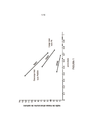
[035] A Figura 1 é um gráfico de proporção de material ativo para carbono (proporção volumétrica) versus porosidade, para vários eletrodos negativos usado em uma célula de ácido de chumbo, todos con-feccionados com material ativo, carregado em uma matriz de carbono,[035] Figure 1 is a graph of ratio of active material to carbon (volumetric ratio) versus porosity, for various negative electrodes used in a lead acid cell, all con-closed with active material, loaded in a carbon matrix. ,
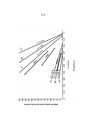
[036] A Figura 2 é um gráfico de áreas da taxa de material ativo de carbono (proporção volumétrica) versus porosidade, que também inclui os vários eletrodos na Figura 1,[036] Figure 2 is a plot of areas of the rate of active carbon material (volumetric ratio) versus porosity, which also includes the various electrodes in Figure 1,
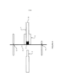
[037] A Figura 3a mostra esquematicamente um eletrodo de fibra de carbono com uma projeção para conexão externa do eletrodo formado sobre o material de fibra de carbono pressionando a carcaça, A Figura 3b mostra uma diferente forma de projeção com uma adição de guia, e a Figura 3c mostra um corte transversal de várias camadas de material de fibra de carbono com uma projeção,[037] Figure 3a schematically shows a carbon fiber electrode with a projection for external connection of the electrode formed on the carbon fiber material by pressing on the housing, Figure 3b shows a different form of projection with a guide addition, and Figure 3c shows a cross-section of several layers of carbon fiber material with a projection,
[038] A Figura 4 mostra esquematicamente um eletrodo de uma modalidade da invenção de um lado com um fio de metal ou fita anexada a um lado como um coletor de corrente em macroescala,[038] Figure 4 schematically shows an electrode of a modality of the invention on one side with a metal wire or tape attached to one side as a macroscale current collector,
[039] A Figura 5 é um corte transversal esquemático através de um eletrodo de uma modalidade da invenção com um fio de metal ou fita anexado a um lado como um coletor de corrente em macroescala,[039] Figure 5 is a schematic cross-section through an electrode of an embodiment of the invention with a metal wire or tape attached to one side as a macroscale current collector,
[040] A Figura 6 é um corte transversal esquemático através de um eletrodo é composta por duas seções de material de eletrodo de uma modalidade da invenção com um fio de metal ou fita incorporado ou imprensado entre um coletor de corrente em macroescala,[040] Figure 6 is a schematic cross-section through an electrode. It consists of two sections of electrode material of a modality of the invention with a metal wire or tape incorporated or sandwiched between a current collector in a macroscale,
[041] A Figura 7 é uma vista do corte transversal esquemático ilustrando a divisão de feltro para formar material de eletrodo de fibra de carbono de algumas modalidades da invenção,[041] Figure 7 is a schematic cross-sectional view illustrating the division of felt to form carbon fiber electrode material of some embodiments of the invention,
[042] A Figura 8 ilustra esquematicamente uma forma do reator para a ativação contínua ou não contínua de um material de fibra de carbono para uso como um material coletor de corrente de acordo com a invenção,[042] Figure 8 schematically illustrates a shape of the reactor for the continuous or non-continuous activation of a carbon fiber material for use as a current-collecting material according to the invention,
[043] A Figura 9 é uma vista esquemática de perto dos eletrodos e o trajeto material entre os eletrodos do reator da Figura 8,[043] Figure 9 is a schematic close-up view of the electrodes and the material path between the electrodes of the reactor in Figure 8,
[044] A Figura 10 mostra um teste do algoritmo DCA referido na descrição subsequente do trabalho experimental,[044] Figure 10 shows a test of the DCA algorithm referred to in the subsequent description of the experimental work,
[045] A Figura 11 mostra o desempenho de alta taxa de DCA de dois eletrodos compostos N359 e 371 referidos na descrição subsequente do trabalho experimental,[045] Figure 11 shows the high DCA rate performance of two composite electrodes N359 and 371 referred to in the subsequent description of the experimental work,
[046] A Figura 12 mostra o desempenho do CCA do eletrodo N349 referindo-se a descrição subsequente do trabalho experimental, como testado utilizando SAE J537 a uma taxa elevada de 310 mA/cm quadrado de área de superfície de eletrodo enfrentando outro eletrodo,[046] Figure 12 shows the CCA performance of the N349 electrode referring to the subsequent description of the experimental work, as tested using SAE J537 at a high rate of 310 mA / cm square of electrode surface area facing another electrode,
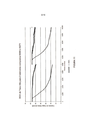
[047] A Figura 13 mostra a corrente versus sobrepotencial de carga (linha de Tafel) do eletrodo 411 referido na descrição subsequente do trabalho experimental, em comparação com um eletrodo tradicional, demonstrando propriedades semelhantes ao consumo de água,[047] Figure 13 shows the current versus charge overpotential (Tafel line) of electrode 411 referred to in the subsequent description of the experimental work, compared to a traditional electrode, demonstrating properties similar to water consumption,
[048] A Figura 14 mostra a corrente versus sobrepotencial de carga (linha de Tafel) do eletrodo 305 referido na descrição subsequente do trabalho experimental, mas são mostrados menos propriedades de consumo de água desejável do que um eletrodo tradicional,[048] Figure 14 shows the current versus charge overpotential (Tafel line) of electrode 305 referred to in the subsequent description of the experimental work, but less desirable water consumption properties are shown than a traditional electrode,
[049] A Figura 15 mostra o desempenho de alta taxa de DCA do eletrodo 409, um eletrodo longo de 60mm com um coletor de corrente do fio, referidas na descrição subsequente do trabalho experimental, o que demonstra o bom desempenho de DCA em comparação com um eletrodo tradicional,[049] Figure 15 shows the high DCA rate performance of the 409 electrode, a 60mm long electrode with a wire current collector, referred to in the subsequent description of the experimental work, which demonstrates the good DCA performance compared to a traditional electrode,
[050] A Figura 16 mostra o desempenho de alta taxa de DCA do eletrodo 356 enquanto 60mm de comprimento, sem nenhum coletor de corrente de fio, referida na descrição subsequente do trabalho experimental, que tem desempenho DCA menos do que um eletrodo com um coletor de corrente do fio, mas ainda melhor do que um eletrodo tradicional,[050] Figure 16 shows the high DCA rate performance of the 356 electrode as long as 60mm in length, with no wire current collector, referred to in the subsequent description of the experimental work, which has less DCA performance than an electrode with a collector current of the wire, but even better than a traditional electrode,
[051] A Figura 17 mostra o desempenho de alta taxa de DCA para eletrodo 356 referido na descrição subsequente do trabalho experimental, após 35.000 ciclos iniciais (mostrado na Figura 16) e reduzido no comprimento de 30mm e então testados com a mesma densidade de corrente carga como antes e mostra o excepcional desempenho de DCA, e[051] Figure 17 shows the high DCA rate performance for
[052] A Figura 18 mostra o desempenho de DCA do eletrodo 410 quando usando o teste de Axion DCA, em comparação com o desempenho de DCA típico de uma tradicional bateria de chumbo-ácido.[052] Figure 18 shows the DCA performance of electrode 410 when using the Axion DCA test, compared to the typical DCA performance of a traditional lead-acid battery.
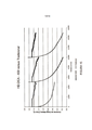
[053] Referindo-se à Figura 1, que é um gráfico da taxa de material ativo de carbono (proporção volumétrica) versus porosidade, em uma modalidade de uma bateria de chumbo-ácido ou célula de acordo com a invenção inclui pelo menos um eletrodo que compreende um coletor de corrente um material fibroso condutor composto por porosi-dade (sendo o volume fracionário ocupado pelos poros entre o chumbo e fibras condutoras) quando totalmente carregado pelo menos 0,3 de uma taxa de carregamento em massa de chumbo (sob qualquer forma) para a massa de fibras condutoras, quando convertido em relação volume na faixa de sobre 0,7:1 ou cerca de 1:1 a cerca de 15:1 ou cerca de 10:1. (e supondo que a conversão completa de todo o material ativo de Pb quando totalmente carregada). Em algumas modalidades a porosidade é entre 0,3 e 0,9, entre sobre 0,3 e 0,85, entre sobre 0,3 e 0,80, entre sobre 0,5 e 0,98, entre sobre 0,7 e 0,95, entre sobre 0,5 e 0,98, ou entre 0,8 e 0,95 e o volume carregando a proporção do material ativo quando convertida para fibras condutoras Pb é entre aproximadamente 0,7:1 ou aproximadamente 1:1 e aproximadamente 7:1, entre aproximadamente1,5:1 e cerca de 5:1, ou aproximadamente 2:1 e aproximadamente 3:1.[053] Referring to Figure 1, which is a graph of the rate of active carbon material (volumetric proportion) versus porosity, in a modality of a lead-acid battery or cell according to the invention includes at least one electrode which comprises a current collector a conductive fibrous material composed of porosity (the fractional volume occupied by the pores between lead and conductive fibers) when fully charged with at least 0.3 of a mass lead charge rate (under any shape) for the mass of conductive fibers, when converted to volume in the range of about 0.7: 1 or about 1: 1 to about 15: 1 or about 10: 1. (and assuming the complete conversion of all active Pb material when fully loaded). In some modalities the porosity is between 0.3 and 0.9, between about 0.3 and 0.85, between about 0.3 and 0.80, between about 0.5 and 0.98, between about 0.7 and 0.95, between about 0.5 and 0.98, or between 0.8 and 0.95 and the volume carrying the proportion of the active material when converted to conductive fibers Pb is between approximately 0.7: 1 or approximately 1 : 1 and approximately 7: 1, between approximately 1.5: 1 and approximately 5: 1, or approximately 2: 1 and approximately 3: 1.
[054] A razão do volume de material ativo para o volume de carbono refere-se ao volume do Pb-contendo material ativo na matriz fibrosa condutora. A porosidade refere-se ao volume vazio entre as partículas do material ativo e a matriz fibrosa condutora, dividido pelo volume total. A relação do volume de sólidos contra a porosidade para um número de eletrodos diferentes descritos nos exemplos experimentais subsequentes é mostrada na Figura 1. A Figura 1 permite que diferentes matrizes porosas, variação do grau de enchimento porosidade esta matriz com material sólido ativo, por exemplo, na colagem e variação no estado de carga. Cada linha é desenhada entre a relação do volume e porosidade por duas formas extremas de torque ativo contidas em uma matriz de carbono determinada. Para a maioria dos ciclos eletroquímicos estas duas formas são Pb e PbSO4. Eletrodos feitos com uma matriz de carbono específico ocupam uma única linha na ta- bela e passam pelo ponto de matriz porosidade com nenhum material ativo. A extensão do carregamento de material ativo (e o formulário está em, por exemplo, PbSO4 ou Pb) determina qual ponto sobre a linha (reta) o eletrodo é (atualmente) representada por, tendo em conta as diferentes densidades de diferentes formas, e quanto de cada um está presente. Por exemplo, se a matriz é inicialmente carregada com PbSO4 e então totalmente carregada para Pb, que esta formação é representada por viajar ao longo de uma seção da linha, "totalmente descarregada" para "completamente carregada". Se a matriz é inicialmente carregada com PbO e então totalmente carregada para converter isso em Pb, em seguida, uma linha diferente é desenhada para representar o caminho de PbO para Pb. No entanto após esta primeira conversão para Pb, o caminho seguido em qualquer ciclo subsequentes seguirá a linha entre Pb e PbSO4. Assim, de descarga/carga de carga completa agora em diante será representada por percursos ao longo da mesma linha como quando inicialmente carregados com PbSO4. Só quando está completamente carregada (ou seja, em 100% Pb) será o eletrodo usando PbO como o precursor ser representado na linha de PbSO4/Pb mais útil e, posteriormente, ou seja, durante os ciclos de mais, o caminho de eletrodo será nessa linha. As linhas de marcação 349, 363, 441 na Figura 1 são para eletrodos a construção do que é descrita nos exemplos experimentais subsequentes. Os pontos mais baixos de cada linha representam as condições onde todo o material carregado ativo foi convertido para Pb. No entanto após esta primeira conversão para Pb, o percurso seguido em qualquer ciclo subsequente seguirá a linha entre Pb e PbSO4.Assim,a descar- ga/carga da carga completa agora em diante será representada por caminhos ao longo da mesma linha como quando inicialmente carregado com PbSO4.Somente quando está totalmente carregada (ou seja em 100% Pb) será o eletrodo usando PbO como o precursor ser re- presentado na linha de PbSO4/Pb mais útil e, posteriormente, ou seja durante os ciclos adicionais, o percurso do eletrodo será nessa linha. As linhas rotulagem 349, 363, 441 na Figura 1 são para eletrodos a construção do que é descrita nos exemplos experimentais subsequentes. Os pontos menos elevados de cada linha representa as condições onde todo o material ativo carregado foi convertido em Pb.[054] The ratio of the volume of active material to the volume of carbon refers to the volume of Pb-containing active material in the conductive fibrous matrix. Porosity refers to the void volume between the particles of the active material and the conductive fibrous matrix, divided by the total volume. The relationship of the volume of solids against porosity for a number of different electrodes described in the subsequent experimental examples is shown in Figure 1. Figure 1 allows different porous matrices, varying the degree of porosity filling this matrix with active solid material, for example , in bonding and variation in the state of charge. Each line is drawn between the volume and porosity ratio by two extreme forms of active torque contained in a given carbon matrix. For most electrochemical cycles these two forms are Pb and PbSO4. Electrodes made with a specific carbon matrix occupy a single line on the table and pass through the porosity matrix point with no active material. The extent of the loading of active material (and the form is, for example, PbSO4 or Pb) determines which point on the (straight) line the electrode is (currently) represented by, taking into account the different densities in different ways, and how much of each is present. For example, if the matrix is initially loaded with PbSO4 and then fully charged to Pb, this formation is represented by traveling along a section of the line, "fully discharged" to "fully charged". If the matrix is initially loaded with PbO and then fully loaded to convert this to Pb, then a different line is drawn to represent the path from PbO to Pb. However after this first conversion to Pb, the path followed in any cycle Subsequent lines will follow the line between Pb and PbSO4. Thus, discharge / full load loading from now on will be represented by paths along the same line as when initially loaded with PbSO4. Only when it is fully charged (that is, at 100% Pb) will the electrode using PbO as the precursor be represented in the most useful PbSO4 / Pb line, and later, that is, during the cycles of more, the electrode path will be in that line. Marking lines 349, 363, 441 in Figure 1 are for electrodes the construction of what is described in the subsequent experimental examples. The lowest points of each line represent the conditions where all active loaded material has been converted to Pb. However, after this first conversion to Pb, the path followed in any subsequent cycle will follow the line between Pb and PbSO4. ga / charge of the full charge now onwards will be represented by paths along the same line as when initially charged with PbSO4. Only when it is fully charged (ie at 100% Pb) will the electrode be used using PbO as the precursor to be represented in the most useful PbSO4 / Pb line and, subsequently, that is, during additional cycles, the electrode path will be in that line. The labeling lines 349, 363, 441 in Figure 1 are for electrodes the construction of what is described in the subsequent experimental examples. The lowest points of each line represent the conditions where all the loaded active material has been converted to Pb.
[055] A porosidade dentro dos eletrodos de uma célula de chumbo-ácido ou bateria é importante para ambos contendo um dos materiais ativos — o ácido — e para permitir o acesso de íons para a superfície que fornece ou aceita elétrons. Expressamos este volume como a fração do volume total ('porosidade') da parte do eletrodo que contém o eletrólito. A proporção do volume de chumbo para volume de fibras condutoras tais como fibra de carbono refere-se ao equilíbrio entre a matéria (Pb) potencialmente capaz de ceder a carga ou aceitá-lo e a questão da fibra condutora, tais como fibra de carbono, fornecendo um canal para os elétrons e, opcionalmente, também uma superfície catalítica para as reações eletroquímicas. Esta relação pode ser expressa como uma relação de volume. Volume e razões de massa podem ser calculados para o estado totalmente carregado (onde só Pb existe) e estado totalmente descarregado (somente PbSO4). Em carga normal de ciclo e descarga, a descarga termina antes de reagir 100% do PbSO4. Qualquer eletrodo dado pode ser caracterizado por dois parâmetros: 1. A porosidade de matriz antes de carregar com material ativo (ou mais convenientemente a fração de volume de matriz que é menos 1 esta porosidade) e 2. A relação de volume do material ativo e uma matriz de carbono quando o material ativo ter sido totalmente convertido para chumbo. Um parâmetro adicional pode ser representado no gráfico. A utilização de chumbo para fornecer a carga é a fração do total caminho percorrido de Pb para PbSO4 que o eletrodo é capaz, durante a descarga.[055] The porosity within the electrodes of a lead-acid cell or battery is important for both containing one of the active materials - the acid - and for allowing ions to access the surface that supplies or accepts electrons. We express this volume as the fraction of the total volume ('porosity') of the part of the electrode that contains the electrolyte. The proportion of lead volume to volume of conductive fibers such as carbon fiber refers to the balance between matter (Pb) potentially capable of yielding or accepting the charge and the question of conductive fiber, such as carbon fiber, providing a channel for electrons and, optionally, also a catalytic surface for electrochemical reactions. This relationship can be expressed as a volume relationship. Volume and mass ratios can be calculated for the fully charged state (where only Pb exists) and the fully discharged state (only PbSO4). At normal cycle load and discharge, the discharge ends before reacting 100% of PbSO4. Any given electrode can be characterized by two parameters: 1. The porosity of the matrix before loading with active material (or more conveniently the fraction of matrix volume that is minus 1 this porosity) and 2. The volume ratio of the active material and a carbon matrix when the active material has been fully converted to lead. An additional parameter can be represented in the graph. The use of lead to supply the charge is the fraction of the total path traveled from Pb to PbSO4 that the electrode is capable of during the discharge.
[056] A razão do volume que é de importância para as taxas de reação é a porosidade do material de eletrodo e partículas que contêm chumbo. Esta porosidade é necessária para permitir os íons de ácido e Pb + + de se difundir para e a partir da superfície de reação.[056] The volume ratio that is of importance for reaction rates is the porosity of the electrode material and lead-containing particles. This porosity is necessary to allow the acid and Pb + + ions to diffuse to and from the reaction surface.
[057] A Figura 2 é semelhante à Figura 1, mas também mostra linhas caracterizadas por determinadas frações de volume de matriz de carbono que definem áreas de relação de material ativo de carbono (proporção volumétrica) versus porosidade. A linha a1 marcada C = 2% estende-se de um valor de porosidade do eixo x de 98% com uma inclinação de -1/0,02 e linha a2 marcada C = 30% estende-se de um valor de porosidade eixo x de 70% com uma inclinação de -1/0,3. Eletrodos que, quando totalmente carregados, tem uma porosidade e uma razão de carga de massa de chumbo de fibras condutoras quando convertido em relação ao volume, que define um ponto na área entre as linhas a1 e a2 são eletrodos de modalidades da invenção.[057] Figure 2 is similar to Figure 1, but it also shows lines characterized by certain carbon matrix volume fractions that define areas of active carbon material ratio (volumetric proportion) versus porosity. The a1 line marked C = 2% extends from an x-axis porosity value of 98% with a slope of -1 / 0.02 and a2 line marked C = 30% extends from an x-axis porosity value. 70% with a slope of -1 / 0.3. Electrodes that, when fully charged, have a porosity and a lead mass charge ratio of conductive fibers when converted to volume, which defines a point in the area between lines a1 and a2, are electrodes of the modalities of the invention.
[058] A linha b1 marcada C = 3% estende-se de um valor de porosidade do eixo x de 97% com uma inclinação de - 1/0,03 e linha b2 marcada C = 20% estende-se de um valor de porosidade eixo x de 80% com uma inclinação de -1/0,2. Eletrodos que, quando totalmente carregado, tem uma porosidade e um em relação ao volume, que define um ponto na área entre as linhas de fibras condutoras quando convertido em relação ao volume que definem um ponto na área entre as linhas a1 e a2 são eletrodos de modalidades preferenciais da invenção.[058] Line b1 marked C = 3% extends from a x-axis porosity value of 97% with an inclination of - 1 / 0.03 and line b2 marked C = 20% extends from a value of 80% x-axis porosity with a slope of -1 / 0.2. Electrodes that, when fully charged, have a porosity and one in relation to the volume, which defines a point in the area between the lines of conductive fibers when converted in relation to the volume that define a point in the area between the lines a1 and a2, are electrodes of preferred embodiments of the invention.
[059] A linha c1 marcada C = 4% estende-se de um valor de porosidade do eixo x de 96% com uma inclinação de - 1/0,04 e marcada de linha c2 C = 15% estende-se de um valor de porosidade eixo x de 85% com uma inclinação de -1/0.15. Eletrodos que, quando totalmente carregado, tem uma polaridade e razão de carga de massa de chumbo para a massa de fibras condutoras quando convertidos em relação ao volume, que define um ponto na área entre as linhas a1 e a2 são ele-trodos de modalidades mais preferidas da invenção. Em particular tais eletrodos podem ser utilizados para a formação de células e/ou baterias com melhorado ou relativamente alta DCA e CCA e podem também ter baixíssimo consumo de água, que são particularmente adequados para uso em veículos híbridos.[059] The line c1 marked C = 4% extends from a porosity value of the x-axis of 96% with an inclination of - 1 / 0.04 and marked line c2 C = 15% extends from a value x-axis porosity of 85% with a slope of -1 / 0.15. Electrodes that, when fully charged, have a polarity and charge ratio of lead mass to mass of conductive fibers when converted in relation to volume, which defines a point in the area between lines a1 and a2, are electrodes of more modalities of the invention. In particular, such electrodes can be used for the formation of cells and / or batteries with improved or relatively high DCA and CCA and can also have very low water consumption, which are particularly suitable for use in hybrid vehicles.
[060] A inclinação das linhas a1 & a2, b1 & b2 e c1 & c2 é descrita pela fórmula relativa polaridade e a relação entre a massa de chumbo à massa de fibra condutora:
[061] O desempenho de ciclo pode depender de manter um tamanho apropriadamente pequeno de partícula para as partículas Pb e PbSO4 depois de muitos ciclos. Este tamanho de partícula pequena dá uma área de superfície suficiente para dissolução suficiente de PbSO4 ou Pb dentro do Pb + + para dar as taxas e correntes necessárias, quando as partículas estão perto de uma superfície de fibra de carbono, que catalisa as reações de criação de corrente. O tamanho das partículas após muitos ciclos pode ser relacionado com o tamanho do afastamento interfibra entre as fibras condutoras, para que as partículas se encaixam entre eles. Assim, com fibras condutoras de menor diâmetro na mesma fração fibra volume total as lacunas entre estas serão proporcionalmente menores e também as partículas ativas serão proporcionalmente menores. Assim, áreas de superfície superiores e taxas mais elevadas podem ser alcançadas com fibras menores.[061] Cycle performance may depend on maintaining an appropriately small particle size for Pb and PbSO4 particles after many cycles. This small particle size gives enough surface area for sufficient dissolution of PbSO4 or Pb within Pb ++ to give the necessary rates and currents, when the particles are close to a carbon fiber surface, which catalyzes the creation reactions due. The size of the particles after many cycles can be related to the size of the inter-fiber spacing between the conductive fibers, so that the particles fit between them. Thus, with conductive fibers of smaller diameter in the same fiber fraction total volume, the gaps between them will be proportionally smaller and also the active particles will be proportionally smaller. Thus, higher surface areas and higher rates can be achieved with smaller fibers.
[062] Em relação à razão de tamanho de partícula de diâmetro da fibra condutora, enquanto as a partículas alteram de tamanho extensivamente durante o ciclo de eletrodo, o tamanho da partícula final é um tanto independente do tamanho da partida. Entretanto, o tamanho inicial deve ser escolhido suficientemente pequeno para caber facilmente entre as fibras, tais como a menos de aproximadamente 10 mícrons para fibras de diâmetro de 7 ou 8 mícrons, por exemplo. Espera-se que a ação de erosão de cada fibra de carbono das partículas PbSO4 circundante durante o carregamento mantenha estas de crescer mais sobre muitos ciclos. Assim, 'sulfatação' pode ser reduzida ou evitada e longo ciclo de vida obtido.[062] Regarding the conductive fiber diameter particle size ratio, while the particles change in size extensively during the electrode cycle, the size of the final particle is somewhat independent of the size of the match. However, the initial size must be chosen small enough to fit easily between the fibers, such as less than approximately 10 microns for fibers with a diameter of 7 or 8 microns, for example. The erosion action of each carbon fiber of the surrounding PbSO4 particles is expected during loading to keep them from growing further over many cycles. Thus, 'sulfation' can be reduced or avoided and the long life cycle achieved.
[063] Em um estado, o material fibroso condutor pode ser um material tecido (que compreende fibras de urdidura e em trama que se cruzam), um material entrelaçado ou um material não tecido, como material de feltro. O material coletor de corrente de preferência tem resistividade de massa inferior a 10 mm Q e, de preferência, menos de 1 Q mm ou 0,1 Q mm. O material pode incluir um material como um material de fibra de carbono ou tal como um tecido ou malha ou tecido não tecido ou fibra de carbono feltro. Matérias não tecidos com fibra de emaranhamento aleatória e interseções podem ser vantajoso em relação aos materiais de tecido com cruzamentos regulares de fibras de gráfico e de gráfico em ângulos retos.[063] In one state, the conductive fibrous material may be a woven material (which comprises intersecting warp and weft fibers), an interlaced material or a non-woven material, such as felt material. The current collecting material preferably has a resistivity of less than 10 mm Q and preferably less than 1 mm or 0.1 mm. The material can include a material such as a carbon fiber material or such as a fabric or mesh or non-woven fabric or carbon fiber felt. Nonwoven materials with random entanglement fiber and intersections can be advantageous over fabric materials with regular intersections of graph and graph fibers at right angles.
[064] O material de fibra de carbono adequado pode incluir ou ser derivado de rayon, poliacrilonitrila, resina de fenol ou materiais de piche.[064] Suitable carbon fiber material may include or be derived from rayon, polyacrylonitrile, phenol resin or tar materials.
[065] Normalmente o material fibroso condutor tem comprimento e dimensões de largura em um grande plano material e espessura média perpendicular do referido plano maior do material, que pode ser, por exemplo, aproximadamente 0,2 mm ou aproximadamente 1 mm e/ou menos de 5 mm ou menos de 3 mm ou menos de 2 mm.[065] Normally the conductive fibrous material has length and width dimensions in a large material plane and average thickness perpendicular to said larger plane of the material, which can be, for example, approximately 0.2 mm or approximately 1 mm and / or less 5 mm or less than 3 mm or less than 2 mm.
[066] Em pelo menos algumas modalidades o material fibroso condutor também tem uma média de espaçamento entre fibras condutoras na faixa de aproximadamente 0,5 a aproximadamente 10 vezes ou aproximadamente 1 e aproximadamente 5 vezes o diâmetro de fibras, ou menos de aproximadamente 20 mícrons, ou menos de aproximadamente 10 mícrons e um diâmetro de fibras condutoras de menos de aproximadamente 10 mícrons.[066] In at least some embodiments the conductive fibrous material also has an average spacing between conductive fibers in the range of approximately 0.5 to approximately 10 times or approximately 1 and approximately 5 times the diameter of fibers, or less than approximately 20 microns , or less than approximately 10 microns and a conductive fiber diameter of less than approximately 10 microns.
[067] O feltro ou outro material de eletrodo não tecido planar pode ser produzido a espessura muito baixa, como por exemplo, a 2,5 mm ou menos de espessura, dividindo o material mais grosso no plano. Ou seja, o material pode ser cortado em seu plano uma ou mais vezes para dividir um material não tecido mais grosso em várias folhas de comprimento e largura semelhantes, mas reduz a espessura para a folha de partida. Isso é ilustrado esquematicamente na Figura 6, que mostra a lâmina de corte fino 60 que passa continuamente ao redor e é conduzida por rolos de comando 61 e 62, no plano fatiado folha de feltro de carbono 63 na cama 64 para formar duas folhas de feltro de carbono do mesmo comprimento e largura, mas metade da espessura. Cada folha de carbono resultante pode estar ainda em um plano dividido.[067] Felt or other non-woven planar electrode material can be produced at very low thickness, such as 2.5 mm or less in thickness, by dividing the thicker material in the plane. That is, the material can be cut in its plane one or more times to divide a thicker non-woven material into several sheets of similar length and width, but it reduces the thickness for the starting sheet. This is illustrated schematically in Figure 6, which shows the
[068] O material de fibra de carbono tecida pode ser tecido de estopa de fibra de carbono que foram 'rompida por estiramento' ou seja, uma estopa (maço) de um número maior de filamentos de fibra de carbono contínuo é esticado após a fabricação para quebrar filamentos contínuos individuais em filamentos mais curtos e separados longitudinalmente nas extremidades dos filamentos em cada pausa, que tem o efeito de reduzir a contagem de filamentos da estopa de fibra de carbono. A contagem do filamento reduzido resultante de estopa é torcida (como uma corda) para manter a integridade da estopa. Por exemplo, uma estopa de 50.000 filamentos contínuos pode ser rompida por esti- ramento para produzir uma estopa mais longa composta por 600 fila-mentos individuais mais curtos que então está torcido, por exemplo.[068] The woven carbon fiber material can be woven from carbon fiber tow which has been 'broken by stretch' ie a tow (bundle) of a greater number of continuous carbon fiber filaments is stretched after fabrication to break individual continuous filaments into shorter and longitudinally separated filaments at the ends of the filaments at each break, which has the effect of reducing the filament count of the carbon fiber tow. The count of the reduced filament resulting from tow is twisted (like a rope) to maintain the integrity of the tow. For example, a tow of 50,000 continuous filaments can be broken by stretching to produce a longer tow consisting of 600 shorter individual threads that are then twisted, for example.
[069] Em pelo menos algumas modalidades o material condutor fibroso é composto por filamentos de duração média na faixa de 3 a 50 mm.[069] In at least some modalities the fibrous conductive material is composed of filaments of average duration in the range of 3 to 50 mm.
[070] O elétrodo negativo ou eletrodos, o eletrodo positivo ou eletrodos ou ambos, de uma célula ou bateria podem ser formados como acima.[070] The negative electrode or electrodes, the positive electrode or electrodes or both, of a cell or battery can be formed as above.
[071] Em modalidades preferenciais das fibras de coleta de material circulante condutores são inerentemente condutores. Em modalidades preferenciais das fibras do eletrodo são fibras de carbono. No entanto o material de fibra de carbono pode em algumas modalidades ser tratado para aumentar a condutividade. Em outras modalidades as fibras do eletrodo podem ser um material menos condutores de micro- escala, as fibras de que são revestidas com um revestimento condutor ou mais condutor. Em algumas modalidades, as fibras do material coletor de corrente podem ser revestidas com Pb ou um material à base de Pb. Por exemplo, o eletrodo negativo ou eletrodos podem ser revestidos com Pb e o eletrodo positivo revestido com Pb e em seguida em PbO2.[071] In preferential modes of conductive rolling stock collection fibers are inherently conductive. In preferred embodiments of the electrode fibers are carbon fibers. However, the carbon fiber material can in some embodiments be treated to increase conductivity. In other embodiments, the electrode fibers may be a less micro-scale conductive material, the fibers of which are coated with a conductive or more conductive coating. In some embodiments, the fibers of the current collecting material can be coated with Pb or a Pb-based material. For example, the negative electrode or electrodes can be coated with Pb and the positive electrode coated with Pb and then in PbO2.
[072] De preferência o material coletor de corrente e as fibras respectivas são flexíveis, o que ajudará em acomodar as variações de volume do material ativo anexado ao material coletor de corrente durante o ciclo de bateria, e as fibras de microescala podem também reforçar o material ativo, ambas as propriedades, ajudando a reduzir rompimento ("derramamento") de material ativo do elétrodo em uso.[072] Preferably the current collecting material and the respective fibers are flexible, which will help to accommodate the volume variations of the active material attached to the current collecting material during the battery cycle, and the microscale fibers can also reinforce the active material, both properties, helping to reduce breakage ("spillage") of active material from the electrode in use.
[073] Em algumas modalidades o material fibroso condutor compreende do único coletor de corrente do ou cada eletrodo.[073] In some embodiments, the conductive fibrous material comprises the single current collector or each electrode.
[074] Como alternativa a ou cada eletrodo pode compreender uma grade de metal, como um coletor de corrente além do material fibroso de fibra de carbono condutor. Em modalidades preferenciais o material fibroso condutor que compreende um material de fibra de car-bono e a grade metálica é compreendido por uma grade de chumbo. As camadas de fibra de carbono condutoras são ligadas à rede de metal de modo a que a grade recebe uma corrente a partir da(s) cama- da(s) de fibra de carbono e liga o eletrodo exterior dos mesmos[074] As an alternative to or each electrode may comprise a metal grid, as a current collector in addition to the conductive carbon fiber fibrous material. In preferred embodiments, the conductive fibrous material comprising a carbon fiber material and the metallic grid is comprised of a lead grid. The conductive carbon fiber layers are connected to the metal mesh so that the grid receives a current from the carbon fiber layer (s) and connects the outer electrode of the same
[075] Os eletrodos negativo ou positivo ou ambos de cada célula podem incluir uma grade de metal.[075] The negative or positive electrodes or both of each cell can include a metal grid.
[076] Onde o eletrodo é compreendido por uma grade metálica de preferência pelo menos 20% a massa ativa de eletrólito da geração corrente é dispersa através do material fibroso condutor. Em modali-dades preferenciais pelo menos 40%, 50%, 80% ou mais de 80% da massa ativa são dispersas no material fibroso condutor. Assim, menos de 80%, 60%, 50% ou 20% da massa ativa podem ser dispersas na grade de metal (especificamente, dentro de suas aberturas).[076] Where the electrode is comprised of a metallic grid, preferably at least 20%, the active electrolyte mass of the current generation is dispersed through the conductive fibrous material. In preferred modes at least 40%, 50%, 80% or more than 80% of the active mass are dispersed in the conductive fibrous material. Thus, less than 80%, 60%, 50% or 20% of the active mass can be dispersed in the metal grid (specifically, within its openings).
[077] Em algumas modalidades pelo menos 20% mas não mais de 40% da massa ativa é dispersa através do material fibroso condutor.[077] In some embodiments, at least 20% but not more than 40% of the active mass is dispersed through the conductive fibrous material.
[078] Em algumas modalidades o material fibroso condutor está presente como múltiplas camadas de pelo menos um de cada lado da grade metálica. Alternativamente, o material fibroso condutor está presente como uma única camada de um lado da grade metálica.[078] In some embodiments, the fibrous conductive material is present as multiple layers of at least one on each side of the metal grid. Alternatively, the conductive fibrous material is present as a single layer on one side of the metal grid.
[079] A grade de metal pode ter uma área superficial semelhante ou ser de altura e largura de dimensões semelhantes particularmente em um plano maior, para o(s) material(is) fibroso(s) condutor(es), mas em modalidades alternativas da grade metálica pode ter dimensões menores, por exemplo, de menor altura e dimensões de largura e pode incluir, por exemplo, uma tira de chumbo mais estreita entre duas camadas de fibra carbono maiores em ambos os lados respectivos.[079] The metal grid may have a similar surface area or be of similar height and width, particularly on a larger plane, for the conductive fibrous material (s), but in alternative modalities The metal grid may have smaller dimensions, for example, of lower height and width dimensions, and may include, for example, a narrower lead strip between two larger carbon fiber layers on both respective sides.
[080] Normalmente durante a construção da bateria ou célula, o material coletor de corrente em microescala é impregnado sob pressão com uma cola, que de forma preferencial é composta por uma mistura de partículas de Pb e PbO de Pb e PbO e ácido sulfúrico diluído. Alter-nativamente, a cola pode compreender as partículas de sulfato (PbSO4) de chumbo e ácido sulfúrico diluído. Em algumas modalidades a cola na impregnação em eletrodo compreende sulfúrico ácido diluído compreendendo entre mais que 0% e 5%, ou entre 0,25% e aproximadamente 3%, ou entre 0% e aproximadamente 2%, ou entre 0,5 e 2,5% no peso da cola de ácido sulfúrico. As partículas com base em Pb podem incluir partículas moídas ou formados quimicamente que possam ter uma média de tamanho igual ou inferior a 10 mícrons, pequeno suficiente para caber facilmente em espaços entre as fibras.[080] Normally during the construction of the battery or cell, the microscale current collecting material is impregnated under pressure with a glue, which preferably consists of a mixture of Pb and PbO particles from Pb and PbO and diluted sulfuric acid . Alter-natively, the glue may comprise the lead sulfate (PbSO4) particles and diluted sulfuric acid. In some embodiments, the glue on the electrode impregnation comprises diluted sulfuric acid comprising between more than 0% and 5%, or between 0.25% and approximately 3%, or between 0% and approximately 2%, or between 0.5 and 2 , 5% by weight of the sulfuric acid glue. Pb-based particles can include ground or chemically formed particles that can average 10 microns or less in size, small enough to easily fit in spaces between the fibers.
[081] A cola, pode opcionalmente conter outros aditivos tais como o negro de fumo, sulfato de bário e/ou um expansor como um lignosulfonato. O sulfato de bário age como um cristal de semente para cristalização de sulfato de chumbo, incentivando o chumbo a reação de sulfato de chumbo. Um expansor ajuda impedir a aglomeração de partículas de sulfato na placa negativa, por exemplo, formando uma massa sólida de sulfato de chumbo durante a descarga.[081] The glue can optionally contain other additives such as carbon black, barium sulfate and / or an expander such as lignosulfonate. Barium sulfate acts as a seed crystal for lead sulphate crystallization, encouraging lead to lead sulphate reaction. An expander helps to prevent the aggregation of sulfate particles on the negative plate, for example, forming a solid mass of lead sulfate during discharge.
[082] Por exemplo, um expansor pode incluir entre aproximadamente 0,05% para aproximadamente 0,25% ou aproximadamente 0,09 a 0,2% ou 0,09% para 0,17% em peso da massa na impregnação. Verificou-se que a inclusão de um composto de expansor na cola pode ter um efeito benéfico sobre o desempenho no CCA, mas um efeito negativo no desempenho do DCA. Convencionalmente um expansor em uma concentração de cerca de 0,2% ou mais é adicionado à cola. Verificou-se que uma concentração de expansor de entre aproximadamente 0,09% para aproximadamente 0,15% em peso da cola na impregnação tem tanto bom desempenho DCA e CCA pode ser alcançado.[082] For example, an expander may include between approximately 0.05% to approximately 0.25% or approximately 0.09 to 0.2% or 0.09% to 0.17% by weight of the mass in the impregnation. It was found that the inclusion of an expander compound in the glue can have a beneficial effect on the performance in the CCA, but a negative effect on the performance of the DCA. Conventionally an expander at a concentration of about 0.2% or more is added to the glue. It has been found that an expander concentration of between approximately 0.09% to approximately 0.15% by weight of the glue in the impregnation has both good DCA and CCA performance can be achieved.
[083] A cola também pode incluir Ag, Bi, Zn ou um composto de qualquer um deles, como um agente antigaseificante.[083] The glue can also include Ag, Bi, Zn or a compound of any of them, as an anti-gassing agent.
[084] A cola pode ter viscosidade relativamente baixa, por exemplo, o fluxo ao invés de ser autoapoiado sobre uma superfície horizontal sob a gravidade, a impregnação no material do eletrodo. De preferência a cola tem uma consistência cremosa. Verificou-se que isto seja alcançado onde compreende a cola na impregnação para o eletrodo (maior que 0 mas) menos de 5% em peso de água.[084] The glue can have relatively low viscosity, for example, the flow instead of being self-supported on a horizontal surface under gravity, impregnation in the electrode material. Preferably the glue has a creamy consistency. This has been found to be achieved where the glue in the impregnation to the electrode (greater than 0 but) comprises less than 5% by weight of water.
[085] Para auxiliar a impregnação do material do eletrodo pela cola, uma vibração de baixa frequência, por exemplo, em menos de 2kHz ou menos de 1kHz ou na faixa de 50 a 500 Hz pode ser aplicada na cola ou no material do eletrodo ou em ambos. Ele também foi descoberto útil quando mistura as partículas com base no Pb, ácido sulfú- rico e água da cola, para auxiliar a mistura pela vibração da cola durante a mistura.[085] To assist the impregnation of the electrode material by the glue, a low frequency vibration, for example, at less than 2kHz or less than 1kHz or in the range of 50 to 500 Hz can be applied to the glue or to the electrode material or in both. It has also been found useful when mixing the particles based on Pb, sulfuric acid and glue water, to assist mixing by vibrating the glue during mixing.
[086] Durante a formação da célula inicial (primeiro ciclo de carga e descarga durante os quais as ligações de partículas ativas formam) após a construção da célula ou bateria, primeiro ocorre formação de célula por construir a estrutura de condução, tendo a maioria do Pb no material ativo negativo, construção normalmente com comprimentos de vários milímetros (conectando sequências de talvez mil ou mais partículas de tamanho mícron de ponta a ponta). Nesta fase produz também pequenas partículas de PbSO4. Segundo, estas partículas menores anexam a esta estrutura condutora para fornecer e receber a corrente. Em conformidade com a invenção da grade Pb é substituída ou complementada por um coletor corrente fibroso de microescala e a cola é composta por PbSO4 ou PbO ou partículas Pb (ou outras partículas de compostos de Pb), exigindo durante a formação substancialmente apenas anexar o Pb destes Pb contendo partículas para as fibras mais próximas em material coletor de corrente condutora a micro- escala. Pode ser vantajoso que durante a formação da corrente de carga estar pulsada periodicamente.[086] During the formation of the initial cell (first cycle of charge and discharge during which the active particle bonds form) after the construction of the cell or battery, first cell formation occurs by building the conduction structure, having the majority of the Pb in the negative active material, typically constructed in lengths of several millimeters (connecting strings of perhaps a thousand or more micron-sized particles from end to end). At this stage it also produces small particles of PbSO4. Second, these smaller particles attach to this conductive structure to supply and receive the current. In accordance with the invention of the Pb grid, it is replaced or complemented by a current fibrous microscale collector and the glue is composed of PbSO4 or PbO or Pb particles (or other particles of Pb compounds), requiring during formation substantially only to attach Pb of these Pb containing particles for the closest fibers in micro-scale conductive current collector material. It may be advantageous that during the formation of the charge current it is pulsed periodically.
[087] O material fibroso de coletor de corrente pode ser apoiado mecanicamente, e uma estrutura de apoio mecânico pode também fornecer ligação elétrica de cada eletrodo para os terminais de célula ou bateria (conexão de eletrodos externos). Por exemplo, uma ou mais camadas quadradas ou retangulares adjacentes do material coletor de corrente podem ser suportadas para formar uma placa de bateria planar por uma estrutura periférico metal por todos os lados, ou entre em frente de elementos de estrutura metálica em dois lados opostos. Como alternativa, por exemplo, placas concêntricas cilíndricas positivas e negativas de cada célula podem incluir seções cilíndricas do coletor corrente de microescala, apoiada nas extremidades cilíndrica circulares frames do metal. Geralmente todas as formas de conector externo são referidas neste documento como uma ‘projeção’.[087] The current collector fibrous material can be mechanically supported, and a mechanical support structure can also provide electrical connection from each electrode to the cell or battery terminals (connection of external electrodes). For example, one or more adjacent square or rectangular layers of the current collecting material can be supported to form a planar battery plate by a metal peripheral structure on all sides, or enter in front of metal structure elements on two opposite sides. Alternatively, for example, positive and negative concentric cylindrical plates of each cell can include cylindrical sections of the current microscale collector, supported on the circular cylindrical ends of the metal frames. Generally, all forms of external connector are referred to in this document as a 'projection'.
[088] A Figura 3a esquematicamente mostra eletrodo de fibra de carbono tecido 50 com uma projeção 51 para conexão externa do eletrodo formado sobre o material de fibra de carbono por pressão da carcaça, a Figura 3b mostra uma diferente forma de projeção com uma adição de guia 53 e c da Figura 3 mostra um corte transversal de várias camadas de material de fibra de carbono com uma projeção. A projeção é formada de metal como Pb ou uma liga Pb (doravante ambos conhecidos inclusive como Pb) mas pode ser formada de outro material que conecta eletricamente de preferência por penetração em e/ou entre o material fibroso. De preferência a projeção estende substancialmente totalmente ao longo de uma borda do eletrodo. Por exemplo, se o eletrodo tem uma forma quadrada ou retangular a projeção estende substancialmente o comprimento total de uma extremidade do eletrodo. De preferência a projeção é substancialmente não mais grossa do que o próprio material do eletrodo.[088] Figure 3a schematically shows woven
[089] Em algumas modalidades substancialmente todos ou pelo menos a maioria dos filamentos/fibras do material do eletrodo estendem continuamente o eletrodo entre ou para uma armação de metal ou elementos do quadro a que ambas as extremidades ou pelo menos uma das extremidades das fibras são conectados eletricamente. Um tecido de fibras contínuas pode ser o ideal.[089] In some embodiments substantially all or at least most of the filaments / fibers of the electrode material continuously extend the electrode between or to a metal frame or frame elements to which both ends or at least one end of the fibers are electrically connected. A continuous fiber fabric may be ideal.
[090] A conexão elétrica entre as fibras de carbono e a projeção ou quadro condutor deve ser uma junção de resistência mínima e de forma preferencial cada extremidade da fibra é cercada com um metal fundido que corrige fisicamente e conecta eletricamente a extremidade de fibra para a estrutura do metal, durante a construção da bateria ou célula. A estrutura do metal ou estrutura de elementos podem ser formadas por tiras de metal fundidas ao longo de uma ou mais bordas do material do eletrodo para cercar e incorporar as extremidades da fibra de refrigeração. Opcionalmente as fibras ou tecido podem continuar para além de um ou mais elementos de quadro em uma ou mais bordas para formar outro eletrodo adjacente ou seção de eletrodo. De preferência substancialmente todos ou pelo menos a maioria das fibras do eletrodo em uma direção ou no eixo do plano do material são eletricamente conectado a um elemento de estrutura metálica, não mais que 100 mm a 10 mm afastada onde a fibra começa no material ativo ou em ambas as bordas opostas do material. Esta distância ou o tamanho ou a área de cada seção de material coletor de corrente é determinada principalmente pela resistividade de massa do material coletor de corrente na direção mais condução. Se apenas uma borda do tecido é eletricamente conectada a um elemento de estrutura metálica, de preferência nesse sentido mais condução no tecido é alinhada perpendicularmente à borda conectada para minimizar a resistência geral. Para permitir maior densidade de corrente em um eletrodo sem perda significativa da capacidade, o comprimento do tecido da borda conectado pode ser até cerca de 50 a 100 mm. Um frame do metal alternativamente pode incluir uma folha de metal com aberturas, em um ou ambos os lados do material, deixando as aberturas ou janelas com exclusivamente fibras de carbono carregando a corrente e a coleta do material ativo que eles carregam. Por exemplo, um quadro de eletrodo de altura 200 mm, pode incluir duas janelas de altura cada 100 mm, com uma rede de condução deixada ao redor da borda, para que a distância mais distante de qualquer trave é 50 milímetros. Para cada uma destas regiões de janela, tecido de carbono pode ser espalhado e anexado as barras cruzadas de metal e dentro das bordas.[090] The electrical connection between the carbon fibers and the projection or conductive frame must be a junction of minimum strength and preferably each end of the fiber is surrounded with a molten metal that physically corrects and electrically connects the end of the fiber to the metal structure during the construction of the battery or cell. The metal structure or element structure can be formed by strips of metal fused along one or more edges of the electrode material to surround and incorporate the ends of the cooling fiber. Optionally, the fibers or fabric can continue beyond one or more frame elements at one or more edges to form another adjacent electrode or electrode section. Preferably substantially all or at least most of the electrode fibers in one direction or on the axis of the material plane are electrically connected to a metal frame element, no more than 100 mm to 10 mm apart where the fiber begins in the active material or on both opposite edges of the material. This distance or the size or area of each section of current collecting material is mainly determined by the mass resistivity of the current collecting material in the most conduction direction. If only one edge of the fabric is electrically connected to a metal frame element, preferably in this sense more conduction in the fabric is aligned perpendicularly to the connected edge to minimize the overall strength. To allow greater current density at an electrode without significant loss of capacity, the length of the fabric of the connected edge can be up to about 50 to 100 mm. A metal frame may alternatively include a sheet of metal with openings on one or both sides of the material, leaving the openings or windows with exclusively carbon fibers carrying the chain and collecting the active material they carry. For example, an electrode board with a height of 200 mm, can include two windows of height each 100 mm, with a conduction net left around the edge, so that the furthest distance from any beam is 50 mm. For each of these window regions, carbon fabric can be spread and attached to the metal crossbars and inside the edges.
[091] A Figura 4 mostra esquematicamente um eletrodo 55, de um lado com uma projeção 56 ao longo de uma borda semelhante à Figura 3. Nesta modalidade do eletrodo em um ou ambos os lados de um material de fibra de carbono que compreendem um fio de metal ou fita 57 eletricamente anexado condutivamente, ao material do eletrodo 55 e a projeção 56, para proporcionar um percurso de coleta de corrente adicional de macroescala a partir de fibra de carbono para a projeção de metal 56, além dos caminhos de micro escala através o material de fibra de carbono em si do eletrodo. O fio de metal ou as fitas podem ser ligadas ao material do eletrodo, por exemplo, por alinhavo ou costura com um segmento que não se dissolverá no eletrólito, ou outro material inerte da ligação ácido da bateria de Pb que prenderá o coletor de corrente no lugar, como resina, cimento ou do substrato. O fio de metal ou fitas podem ser passadas para o material do eletrodo durante a fabricação. Alternativamente o fio ou fita ou similar pode ser soldado ao ou impresso sobre o material de eletrodo de fibra de carbono. O fio de metal ou fita(s) podem ser dispostdispostos em uma forma sinuosa em um ou ambos os lados do material de fibra de carbono, como mostrado, estendendo continuamente entre a projeção 56 em uma borda do eletrodo, que beira o fio ou fita feito está ligada para a projeção 56 por sendo incorporado da projeção e no ou em direção a outra borda espaçada do eletrodo como mostrado. Alternativamente o fio ou fita pode estender-se entre talões de metal ao longo de bordas opostas do eletrodo ou uma estrutura em torno do eletrodo. Alternati-vamente novamente separados comprimentos do fio ou fita podem es-tender-se desde a projeção em uma borda de ou para outra borda do eletrodo, ou alternativamente novamente o fio ou fita macrocondutor como descrito pode incluir uma malha de metal ligada a um ou ambos os lados do material da fibra do carbono.[091] Figure 4 schematically shows an
[092] A Figura 5 é um corte transversal esquemático através de um eletrodo 55 com um fio de metal ou fita 56 anexada a um lado do material do eletrodo e a Figura 6 é um corte transversal esquemático através de um eletrodo composto de duas camadas 55a e 55b de material de fibra de carbono com um fio de metal ou fita 56 incorporado ou imprensado entre. As fibras de carbono com fio de metal ou fita entre podem ser compactadas juntas durante a fabricação.[092] Figure 5 is a schematic cross-section through an
[093] Se formado a partir de cobre do fio ou fita ou malha ou similares, incluindo qualquer extremidade exposta respectiva devem ser protegidas da oxidação dentro da célula por revestimento com chumbo ou titânio ou outro metal inerte no ambiente ácido-Pb, por exemplo, imersão a quente, extrusão, ou galvanização. As extremidades do fio ou fita ou malha podem rescindir e ser incorporadas na projeção ou quadro periférico. É importante que, quando o coletor de corrente é sobre a superfície externa do eletrodo que age como o elétrodo negativo o coletor de corrente é protegida da oxidação anódica do elétrodo positivo.[093] If formed from copper wire or tape or mesh or the like, including any exposed end thereof, they must be protected from oxidation within the cell by coating with lead or titanium or another inert metal in the Pb-acid environment, for example, hot dipping, extrusion, or galvanizing. The ends of the wire or ribbon or mesh may terminate and be incorporated into the projection or peripheral frame. It is important that when the current collector is on the outer surface of the electrode that it acts as the negative electrode the current collector is protected from the anodic oxidation of the positive electrode.
[094] De preferência o fio ou fita corre acima e abaixo do comprimento do eletrodo com espaçamento igual em toda a largura do eletrodo sem quaisquer pontos de cruzamento, como indicado na Figura 3, para evitar pontos de acesso locais ocorrendo ou calor acumular em particular áreas e uma coleção mesmo corrente através do eletrodo.[094] Preferably the wire or ribbon runs above and below the length of the electrode with equal spacing across the width of the electrode without any crossing points, as shown in Figure 3, to prevent local access points from occurring or heat build up in particular areas and a collection even current through the electrode.
[095] De preferência o volume do fio ou fita ou malha ou similar sistema corrente macroescala de coleta é menos de aproximadamente 15% do volume do eletrodo (excluindo o talão ou em torno de armação de metal ou similar).[095] Preferably the volume of the wire or tape or mesh or similar current macro-scale collection system is less than approximately 15% of the volume of the electrode (excluding the bead or around metal frame or similar).
[096] Em algumas modalidades, os eletrodos da invenção, caso o composto (também incorporando uma grade metálica) ou não composto (sem uma grade de metal) tenha uma espessura (transversal a um comprimento e largura ou em dimensões do plano do eletrodo) muitas vezes tais como 10, 20, 50 ou 100 vezes menor do que ou qualquer dimensão do plano do eletrodo. A espessura do eletrodo pode ser inferior a 5 ou menos de 3 mm por exemplo. Cada uma das dimensões do eletrodo de comprimento e largura em plano podem ser maiores do que 50 ou 100 mm, por exemplo. Tais eletrodos têm uma forma planar com baixa espessura. Uma forma de eletrodo composto da invenção pode incluir uma grade metálica de cerca de 3,5 mm ou menos, tal como aproximadamente 0,5 mm de espessura, com uma camada de fibra de carbono de aproximadamente 2 mm de espessura ou menos, tal como aproximadamente 0,3 mm de espessura em ambos os lados.[096] In some embodiments, the electrodes of the invention, whether the compound (also incorporating a metal grid) or non-compound (without a metal grid) have a thickness (transversal to a length and width or in dimensions of the electrode plane) often such as 10, 20, 50 or 100 times smaller than or any dimension of the electrode plane. The electrode thickness can be less than 5 or less than 3 mm for example. Each of the electrode dimensions of length and width in plane can be greater than 50 or 100 mm, for example. Such electrodes have a planar shape with low thickness. A form of the composite electrode of the invention may include a metal grid of about 3.5 mm or less, such as approximately 0.5 mm thick, with a layer of carbon fiber approximately 2 mm thick or less, such as approximately 0.3 mm thick on both sides.
[097] Em formas preferenciais, o eletrodo é substancialmente planar e tem uma dimensão de uma projeção metálica para conexão externa ao longo de pelo menos uma borda do eletrodo inferior a 100 mm ou menos de 70 mm, ou menos de 50 mm, ou aproximadamente 30 mm ou menos, por exemplo, (com ou sem um coletor de corrente macroescala). Como alternativa como uma forma de planar pode ser formada a partir de um eletrodo cilíndrico, por exemplo.[097] In preferred forms, the electrode is substantially planar and has a metal projection dimension for external connection along at least one edge of the electrode less than 100 mm or less than 70 mm, or less than 50 mm, or approximately 30 mm or less, for example, (with or without a macroscale current collector). Alternatively as a planar shape it can be formed from a cylindrical electrode, for example.
[098] O material de fibra de carbono para uso como o material do coletor da corrente do eletrodo pode ser tratado termicamente. O tratamento térmico também pode aumentar a condutividade térmica do material, que deve ser suficiente para evitar pontos de acesso locais sobre o eletrodo em uso. As fibras de carbono são geralmente à base de hidrocarbonetos e durante a fabricação, aquecidas a cerca de 1100° C ou mais ("carbonizada"). Para uso como mate rial coletor de corrente em baterias ou células da invenção, material de fibra de carbono pode ser aquecido ainda, geralmente na faixa de 2200 de 2800° C, para ampliar as regiões do carbono que já são aromáticas ou grafí- ticas, aumentando a condutividade elétrica. O tratamento térmico para aumentar a condutividade elétrica e/ou térmica pode ser em uma fornalha resistivamente aquecida, por exemplo, ou pode ser por descarga de arco elétrico onde além de pelo menos algumas ou uma fração maior de carbono não grafítico a partir as fibras de carbono e não mais do que uma pequena fração de carbono grafítico, pode ser evaporada.[098] The carbon fiber material for use as the electrode current collector material can be heat treated. Heat treatment can also increase the thermal conductivity of the material, which should be sufficient to avoid local access points on the electrode in use. Carbon fibers are generally hydrocarbon-based and, during manufacture, heated to about 1100 ° C or more ("carbonized"). For use as a current collector material in batteries or cells of the invention, carbon fiber material can be heated further, usually in the range of 2200 to 2800 ° C, to enlarge the carbon regions that are already aromatic or graphical, increasing electrical conductivity. The heat treatment to increase the electrical and / or thermal conductivity can be in a resistively heated furnace, for example, or it can be by electric arc discharge where in addition to at least some or a larger fraction of non-graphitic carbon from the fibers of carbon and no more than a small fraction of graphitic carbon, can be evaporated.
[099] O material coletor de corrente da fibra de carbono pode ser tratado à temperatura suficiente para aumentar a condutividade de calor. O tratamento térmico pode ser por descarga de arco elétrico. Em determinadas modalidades material de fibra de carbono pode ser tratado por descarga de arco, movendo o material de fibra de carbono para dentro de uma câmara de reação através de um arco elétrico em uma lacuna entre dois eletrodos ou passado um eletrodo para que um arco elétrico que existe entre o eletrodo e o material a uma temperatura eficaz para ativar o material. Na Figura 7, referência numérica 1 indica uma câmara do reator em que a descarga de arco é criada. Os eletrodos 2 e 3 projetam para a câmara do reator 1 e normalmente são montados por mecanismos de eletrodo-alimentação 4 como são conhecidos por aqueles versados na técnica, para que a posição do eletrodo 3, que talvez seja o ânodo e o eletrodo 2, que pode ser o cátodo (as posições do ânodo e cátodo podem ser invertidas), podem ser ajustados para criar o arco e em funcionamento, manter ou, se for necessário ajustar o arco. Um sistema de refrigeração 5 consistindo de tubo de cobre enrolado ao redor de cada eletrodo através do qual água é circulada de bobinas também podem ser dispostas para esfriar o eletrodo. Material de fibra de carbono 8 passa entre eletrodos de 2 e 3 e através do arco durante a operação do reator, como mostrado. Isso é mostrado com mais detalhes na Figura 8. A corrente deve ser suficiente para vaporizar o carbono não grafítico, mas não aciona o modo de fixação do arco localizado a que se recomenda a operação entre 10 A e 20. O material pode entrar na câmara do reator através de uma fenda 12 na câmara do reator e sair através de uma saída semelhante da fenda 13 na câmara do reator do outro lado dos eletrodos. Está previsto um mecanismo para alimentar o material através da câmara do reator. Por exemplo, durante a operação do reator o substrato pode ser desenrolado de uma bobina 9 impulsionado por uma caixa de velocidades que está acoplada a um motor elétrico com um sistema de controle adequado. Durante a operação que no interior do reator é de preferência igual ou ligeiramente acima da pressão atmosférica e o fluxo de gás saindo do reator através da fenda 13 é extraída através de um filtro ou exaustor ou similar. Um gás inerte como nitrogênio, ar- gônio ou hélio, por exemplo, é liberado através da câmara de reação, por exemplo, através da introdução de um fluxo de gás controlada dentro da câmara de reação 1 através de uma das aberturas 11 na base do reator. O ânodo, bem como o carretel que impulsiona a fita é de preferência ligado à terra. Qualquer mecanismo de adoção para coletar o substrato depois que passou através da câmara do reator é também, de preferência ligado à terra, como também é a concha do reator. Referindo-se a Figura 8, pode ser preferível para um eletrodo, que na Figura é o ânodo 3, deve ser posicionado para colidir com o substrato 8 tal que o substrato está tensionado contra esse eletrodo como substrato ultrapassa como mostrado esquematicamente. A descarga de arco elétrico pode vaporizar uma grande fração de carbono não grafíti- co e não mais do que uma fração menor de carbono grafítico do mate rial de fibra de carbono. O método pode ser efetuado na presença de um aditivo de metal introduzido, como um aditivo de Pb.[099] The current-collecting material of the carbon fiber can be treated at a temperature sufficient to increase the heat conductivity. The heat treatment can be by electric arc discharge. In certain embodiments, carbon fiber material can be treated by arc discharge, moving the carbon fiber material into a reaction chamber through an electric arc in a gap between two electrodes or passing an electrode so that an electric arc that exists between the electrode and the material at a temperature effective to activate the material. In Figure 7,
[0100] Um eletrodo de microescala em conformidade com a invenção com uma área de superfície interna dos poros pode fornecer capacidade suficiente para adicionar para carregar aceitação para além da contribuição da eletroquímica. Uma área de eletrodo que está bem úmida e acessível para o eletrólito de ácido pode contribuir mais do que uma capacitância de ordem de magnitude maior do que a dada pela área total da superfície de um material ativo convencional no eletrodo negativo de uma bateria de chumbo-ácido. Pode ter capacidade de dupla camada eletrolítica suficiente para absorver ou entregar vários segundos de alta corrente. Alternativamente, uma bateria da invenção pode compreender um eletrodo separado de elevada área superficial, que se pode compreender material de fibra de carbono tratado com arco conforme descrito neste documento, em paralelo para o ou cada eletrodo negativo ou positivo de célula, para adicionar ou aumentar a capacitância.[0100] A microscale electrode in accordance with the invention with an internal pore surface area can provide sufficient capacity to add to charge acceptance beyond the contribution of electrochemistry. An electrode area that is well moist and accessible to the acid electrolyte can contribute more than a capacitance of an order of magnitude greater than that given by the total surface area of a conventional active material on the negative electrode of a lead battery. acid. It may have sufficient electrolytic double-layer capacity to absorb or deliver several seconds of high current. Alternatively, a battery of the invention may comprise a separate high surface area electrode, which may comprise arc treated carbon fiber material as described in this document, in parallel for the or each negative or positive cell electrode, to add or increase capacitance.
[0101] O tratamento térmico, por exemplo, descarga de arco elétrico pode aumentar a área de superfície dos poros e aumentar a capaci- tância. Também a aplicação e secagem então uma solução Pb(NO3)2 em material de fibra de carbono antes do tratamento do arco pode aumentar o desenvolvimento de área de superfície (aparentemente através da oxidação). Alternativamente, o material pode ser ativado por ativação física como por vapor ou dióxido de carbono em temperaturas em torno de 1000° C, ou por ativação química por so luções de álcalis por exemplo. Ativação normalmente cria poros da nanoescala e mais tipicamente até 50 nm de diâmetro, no material ou na superfície do material. Materiais com extensivos poros menores que cerca de 1 nm pode não ser bons condutores eletrônicos. Poros de 1 nm a 10 nm podem fornecer a área de superfície necessária para uma capacidade significativa, mas os poros bem distribuídos acima de 10 nm também são necessários para fornecer fácil acesso de difusão de íons para a condutividade do eletrólito adequado. Também é necessária condutivi- dade elétrica suficiente dentro do sólido.[0101] Heat treatment, for example, electric arc discharge can increase the surface area of the pores and increase the capacitance. Also the application and drying then a Pb (NO3) 2 solution in carbon fiber material before the arc treatment can increase the development of surface area (apparently through oxidation). Alternatively, the material can be activated by physical activation such as steam or carbon dioxide at temperatures around 1000 ° C, or by chemical activation by solutions of alkalis for example. Activation normally creates pores of the nanoscale and more typically up to 50 nm in diameter, in the material or on the surface of the material. Materials with extensive pores smaller than about 1 nm may not be good electronic conductors. Pores from 1 nm to 10 nm can provide the required surface area for significant capacity, but well-distributed pores above 10 nm are also needed to provide easy ion diffusion access for the proper electrolyte conductivity. Sufficient electrical conductivity within the solid is also required.
[0102] Em algumas modalidades materiais de fibra de carbono tem fixados os nanotubos de carbono (CNTs). O material do mancal CNTs pode ser produzido por tratamento de descarga de arco elétrico do ma-terial de fibra de carbono, ou alternativamente por deposição de vapor químico às temperaturas mais baixas na presença de um catalisador.[0102] In some modalities, carbon fiber materials have fixed carbon nanotubes (CNTs). The material of the CNTs bearing can be produced by electric arc discharge treatment of carbon fiber material, or alternatively by chemical vapor deposition at lower temperatures in the presence of a catalyst.
[0103] Como afirmado, em formas preferenciais adequadas para uso em células de veículos híbridos e/ou baterias, que compreende a construção de um eletrodo da invenção pode ter tanto melhorada ou relativamente alto DCA e CCA (DCA medido pelo teste Axion e CCA como medido, por exemplo, de acordo com o SAE J357 CCA, e/ou podem manter DCA ou uma taxa maior de DCA com o aumento do número de ciclos de carga-descarga e também pode ter baixíssimo consumo de água e também pode ter melhorado ou VED relativamente elevado e/ou a vida da bateria melhorada. Modalidades de células ou baterias da invenção podem manter DCA pelo menos 70% ou 80% ou 90% de DCA de partida (quando o primeiro totalmente carregado) depois de 5000 ou 10000 ciclos por exemplo. Modalidades de células ou baterias da invenção podem reter uma DCA média pelo menos 0,6 ou 0,7 ou 0,8 A /Ah por fase a 0,000 ciclos de carregamento usando o teste de DCA Axion. A capacidade de uma bateria é medida em ampe- res/horas, a utilização é a capacidade real da bateria dividida pela capacidade máxima teórica e modalidades das células ou baterias da invenção podem ter maior utilização como uma utilização de pelo menos 55%, 60%, 70% ou 80% ou mais. Exemplos[0103] As stated, in preferred forms suitable for use in cells of hybrid vehicles and / or batteries, comprising the construction of an electrode of the invention can have either improved or relatively high DCA and CCA (DCA measured by the Axion and CCA test as measured, for example, in accordance with SAE J357 CCA, and / or can maintain DCA or a higher rate of DCA with increasing number of charge-discharge cycles and may also have very low water consumption and may also have improved or Relatively high VED and / or improved battery life Modes of cells or batteries of the invention can maintain DCA at least 70% or 80% or 90% of starting DCA (when the first fully charged) after 5000 or 10,000 cycles per The cell or battery modalities of the invention can retain an average DCA of at least 0.6 or 0.7 or 0.8 A / Ah per phase at 0.000 charge cycles using the Axion DCA test. measured in amps / hours, use is the cap the actual battery life divided by the theoretical maximum capacity and modalities of the cells or batteries of the invention may have greater use as a utilization of at least 55%, 60%, 70% or 80% or more. EXAMPLES
[0104] A seguinte descrição de trabalho experimental que é dada a título de exemplo ilustra adicionalmente a invenção. Em alguns dos exemplos um teste DCA é referido e a Figura 10 mostra o algoritmo de teste DCA, segundo os quais um teste de aceitação de carga dinâmica elevada taxa (DCAT) projetado para simular as demandas de stop/ start de veículo micro híbrido no seu sistema de bateria foi aplicada a cada célula. O perfil de teste DCAT é um teste de tempo de vida acelerado, teste de tempo de vida destrutivo que é realizada em um estado constante de carga, que garante que o teste DCAT é independente das questões de calibração e sistema de teste associadas com esse sistema, evitando assim problemas de calibração, normalmente asso-ciados a outros protocolos de teste de vida. O teste DCAT empregado seguiu o perfil de teste Axion DCAT em um sistema de teste de Cadex C8000, onde o perfil de teste consiste das seguintes etapas: • descarga de 0,51C por 60 s • descarga de pulso de 3,15C por 1 s • repouso de 10 s (no final dos quais PDRV (tensão de teste pós descarga) é medido) • Período de carga dinâmica de 1,05C ajustado para manter o PDRV em um determinado ponto de ajuste • 10 s de repouso.[0104] The following description of experimental work which is given by way of example further illustrates the invention. In some of the examples a DCA test is referred to and Figure 10 shows the DCA test algorithm, according to which a high dynamic load acceptance test (DCAT) designed to simulate the stop / start demands of a micro hybrid vehicle in its battery system was applied to each cell. The DCAT test profile is an accelerated life time test, destructive life time test that is performed in a constant state of charge, which ensures that the DCAT test is independent of the calibration and test system issues associated with that system , thus avoiding calibration problems, normally associated with other life test protocols. The DCAT test employed followed the Axion DCAT test profile in a Cadex C8000 test system, where the test profile consists of the following steps: • discharge of 0.51C for 60 s • pulse discharge of 3.15C for 1 s • 10 s rest (at the end of which PDRV (post-discharge test voltage) is measured) • Dynamic load period of 1.05C adjusted to keep the PDRV at a certain set point • 10 s of rest.
[0105] Este perfil de ciclo descrito é iterado para uma contagem de ciclo de 30.000, que se traduz em um período típico de 6 semanas, embora este período é dependente do desempenho da bateria. Cada 5000 ciclos, uma carga completa, seguida por uma descarga profunda medido a capacidade do eletrodo. Para passar neste teste, a célula precisa ser capaz de percorrer o teste DCAT pelo menos 30.000 vezes, mantendo a capacidade pelo menos 2Ah. 30.000 ciclos é representante de uma vida de bateria em um micro híbrido de aproximadamente 3 anos. Exemplo 1 - eletrodo composto de fibra de carbono de papel com gra- de de Pb -N371[0105] This described cycle profile is iterated for a cycle count of 30,000, which translates to a typical 6 week period, although this period is dependent on the performance of the battery. Every 5000 cycles, a full charge, followed by a deep discharge measured at the electrode capacity. To pass this test, the cell must be able to go through the DCAT test at least 30,000 times, while maintaining the capacity for at least 2Ah. 30,000 cycles is representative of a battery life in a micro hybrid of approximately 3 years. Example 1 - carbon fiber composite electrode with Pb grade -N371
[0106] Método: Um eletrodo foi construído a partir de esteira de carbono de papel de carbono fibroso (Z-Mat produzida pela Zoltek) de espessura de 3 mm, fração de carbono em volume ~6%, peso específico ~ 312 g/m2 e o comprimento da fibra de 25 mm. Duas peças foram cortadas nas dimensões de 44 milímetros * 70 milímetros e em seguida divididas em camadas mais finas para produzir camadas individuais de espessura média de 0,26 mm. O eletrodo foi construído colocando uma dessas camadas fibrosas de carbono em cada uma das duas superfícies de uma grade de chumbo.[0106] Method: An electrode was constructed from 3 mm thick carbon fiber carbon paper (Z-Mat produced by Zoltek), carbon fraction in volume ~ 6%, specific weight ~ 312 g / m2 and the fiber length of 25 mm. Two pieces were cut to 44mm * 70mm and then divided into thinner layers to produce individual layers of 0.26mm average thickness. The electrode was constructed by placing one of these fibrous layers of carbon on each of the two surfaces of a lead grid.
[0107] A cola foi preparada com 23,2 g de óxido plúmbeo (lote de óxido plúmbeo comprado da Exide em 2009),4,0 g de ácido sulfúrico diluído, 2,7g de solução aquosa Vanisperse A (expansora) com solução aquosa o suficiente de Vanisperse para atingir 0,10% em peso na cola preparada e 0,187 g de sulfato de bário. A cola foi misturada em um banho de ultrassom por 2 minutos (53 kHz de frequência, a temperatura do tanque de 23°C). Dentre as camadas fibros as foi colocado em uma placa lisa e grade de chumbo e foi então colocado no topo da camada fibrosa. A grade de Pb tinha espessura 2,02 mm, comprimento 66,3 mm, largura de 44,2 mm e fração de volume aberto ~81,6%. A cola foi espalhada sobre a superfície da grade de chumbo até que obteve-se uma distribuição suave de cola na superfície onde todos os bolsos da grade foram enchidos com a cola. Suficiente excesso de cola para encher parcialmente uma camada fibrosa, em seguida, foi espalhado sobre a superfície da grade colada e uma segunda camada fibrosa de carbono, em seguida, colocada em cima. O excesso de cola foi removido a partir de ambas as faces e as bordas laterais do eletrodo. A espessura total do eletrodo colado foi de aproximadamente 2,60 mm.[0107] The glue was prepared with 23.2 g lead lead (batch of lead lead purchased from Exide in 2009), 4.0 g of diluted sulfuric acid, 2.7 g of Vanisperse A aqueous solution (expander) with aqueous solution enough Vanisperse to reach 0.10% by weight in the prepared glue and 0.187 g of barium sulphate. The glue was mixed in an ultrasound bath for 2 minutes (
[0108] A quantidade total de massa úmida carregada no eletrodo composto era de 24,41 g onde a capacidade alcançada (descarga de corrente baixa) era 2,695 Ah (isto é, 60% da capacidade teórica). As-sumindo a cola penetrada/dispersa na grade e as camadas fibrosas uniformemente, 19,8% de NAM disperso nas camadas fibrosas do ele-trodo e o restante estavam na grade de chumbo. No estado totalmente carregado do eletrodo, a razão média entre a massa de Pb ativa e o volume de carbono é 10,03. O espaçamento médio entre as fibras de carbono era de cerca de 23 mícrons. Subsequentemente, o eletrodo foi seco pelo ar por 24 horas à temperatura ambiente (18°C-24°C) e, em seguida, o eletrodo colado foi montado numa célula contendo ele- trólitos de 1,15 sg de H2SO4 com um eletrodo positivo (40% SOC) de cada lado. A célula foi deixada imersa por 24 horas à temperatura ambiente (18°C-24°C) e a formação de célula padrão fo i realizada.[0108] The total amount of wet mass loaded on the compound electrode was 24.41 g where the reached capacity (low current discharge) was 2.665 Ah (that is, 60% of the theoretical capacity). As the glue penetrated / dispersed in the grid and the fibrous layers uniformly disappeared, 19.8% of NAM dispersed in the fibrous layers of the electrode and the rest were in the lead grid. In the fully charged state of the electrode, the average ratio between the active Pb mass and the carbon volume is 10.03. The average spacing between the carbon fibers was about 23 microns. Subsequently, the electrode was air-dried for 24 hours at room temperature (18 ° C-24 ° C) and then the glued electrode was mounted on a cell containing 1.15 sg H2SO4 electrolytes with a positive electrode (40% SOC) on each side. The cell was left immersed for 24 hours at room temperature (18 ° C-24 ° C) and standard cell formation was performed.
[0109] Método(s) de teste e resultados: O eletrólito foi substituído por 1,28 sg de H2SO4 e estabilizado sob quatro ciclos de descarga de corrente baixa (0,06C) antes de ser enviada ao DCA de taxa alta. O teste de aceitação de carga dinâmica de taxa alta (HR-DCAT) foi realizado nas células de acordo com o teste conforme descrito acima e conforme mostrado na Figura 10. Os resultados são mostrados na tabela 1 abaixo. Exemplo 2 - eletrodo composto de tecido de fibra de carbono tratado em arco com grade de Pb -N359[0109] Test method (s) and results: The electrolyte was replaced with 1.28 sg of H2SO4 and stabilized under four low current (0.06C) discharge cycles before being sent to the high rate DCA. The high rate dynamic load acceptance test (HR-DCAT) was performed on the cells according to the test as described above and as shown in Figure 10. The results are shown in table 1 below. Example 2 - electrode composed of carbon fiber fabric treated in an arc with Pb grid -N359
[0110] Método: Um eletrodo foi construído por fita de fibra de carbono tecida à base de tecido de fibra de carbono PAN [poliacrilonitrila] (fabricado por TaiCarbon, Taiwan). O tecido foi tratado em um arco elétrico geralmente conforme descrito anteriormente com referência às Figuras e 8. Este tecido tratado em arco tinha 136 g/m2 de peso espe-cífico, tinha 0,38 mm de espessura, e tinha ~20% de fração de volume de carbono. Dois pedaços do tecido tratado em arco foram cortados no tamanho de 44 mm * 70 mm. Um pedaço do tecido tratado em arco foi colocado numa placa de ultrassom e a grade de chumbo colocada sobre isso. A grade de Pb tinha dimensões de espessura de 1,94 mm, comprimento de 66,7 mm, largura de 44,4 mm, e fração de volume aberto de ~81,1 %. A cola foi preparada e o eletrodo foi colado e construído usando uma segunda camada do tecido de fibra de carbono, tudo preparado conforme descrito no exemplo 1. A espessura total do eletrodo colado era aproximadamente de 3,6 mm.[0110] Method: An electrode was constructed using carbon fiber tape woven from PAN [polyacrylonitrile] carbon fiber fabric (manufactured by TaiCarbon, Taiwan). The fabric was treated in an electric arc generally as previously described with reference to Figures 8 and 8. This arc treated fabric was 136 g / m2 specific weight, 0.38 mm thick, and had ~ 20% fraction of carbon volume. Two pieces of the arc treated fabric were cut to size 44 mm * 70 mm. A piece of the arch-treated fabric was placed on an ultrasound plate and the lead grid placed over it. The Pb grid had dimensions of 1.94 mm in thickness, 66.7 mm in length, 44.4 mm in width, and an open volume fraction of ~ 81.1%. The glue was prepared and the electrode was glued and constructed using a second layer of carbon fiber fabric, all prepared as described in example 1. The total thickness of the glued electrode was approximately 3.6 mm.
[0111] A quantidade total de massa úmida carregada no eletrodo composto era de 28 g, onde a capacidade alcançada (descarga de corrente baixa) era de 2,99 Ah (isto é, 60% da capacidade teórica). Assumindo a cola penetrada/dispersa no volume vazio disponível da grade e as camadas fibrosas uniformemente, 28,1% de NAM disperso nas camadas fibrosas de carbono do eletrodo composto e o restante estavam na grade de chumbo. No estado totalmente carregado do ele-trodo, a razão média entre a massa de Pb ativa e o volume de carbono é 3,20. O espaçamento médio entre as fibras de carbono era de cerca de 15 mícrons.[0111] The total amount of wet mass loaded on the compound electrode was 28 g, where the reached capacity (low current discharge) was 2.99 Ah (that is, 60% of the theoretical capacity). Assuming the glue penetrated / dispersed in the available empty volume of the grid and the fibrous layers evenly, 28.1% of NAM dispersed in the carbon fiber layers of the composite electrode and the rest were in the lead grid. In the fully charged state of the electrode, the average ratio between the mass of active Pb and the volume of carbon is 3.20. The average spacing between the carbon fibers was about 15 microns.
[0112] Subsequentemente, o eletrodo foi seco ao ar, montado numa célula, a célula foi deixada imersa, e em seguida a carga de formação e estabilização foram realizadas na célula, tudo conforme descrito no exemplo 1.[0112] Subsequently, the electrode was air-dried, mounted in a cell, the cell was left immersed, and then the formation and stabilization charge was carried out on the cell, all as described in example 1.
[0113] Método(s) de teste e resultados: O eletrólito foi substituído por 1,28 sg de H2SO4 e estabilizado sob quatro ciclos de descarga de corrente baixa (0,06C) antes de ser enviada ao DCA de taxa alta. O teste de aceitação de carga dinâmica de taxa alta (HR-DCAT) foi realizado nas células de acordo com o teste conforme descrito acima e conforme mostrado na Figura 10. Os resultados são mostrados na tabela 1 abaixo. Tabela 1 - compara os resultados do teste de DCAT dos eletrodos exibidos nos exemplos 1 e 2 acima.
[0114] Método: Um eletrodo foi construído de camadas de fibra de carbono de feltro de carbono tratado em arco Sigracell KFD2.5 EA fa-bricado por SGL Carbon Company, Alemanha). O feltro foi tratado em um arco elétrico geralmente conforme descrito anteriormente com referência às Figuras 7 e 8. O feltro antes do tratamento em arco tinha um peso específico de 248 g/m2, espessura de 2,5 mm, e fração de volume de carbono de ~7%. O material após o tratamento em arco tinha 217 g/m2 de peso específico, tinha 2,4 mm de espessura, e tinha ~6% de fração de volume de carbono.[0114] Method: An electrode was constructed of carbon fiber layers of carbon felt treated in an arc Sigracell KFD2.5 EA manufactured by SGL Carbon Company, Germany). The felt was treated in an electric arc generally as previously described with reference to Figures 7 and 8. The felt before the arc treatment had a specific weight of 248 g / m2, thickness of 2.5 mm, and fraction of carbon volume ~ 7%. The material after arc treatment was 217 g / m2 specific weight, 2.4 mm thick, and had ~ 6% carbon volume fraction.
[0115] O método de colagem para a única camada de feltro é diferente daquele descrito acima para as camadas de tecido. A cola foi preparada começando com 19,5 g de óxido de chumbo (lote de óxido de chumbo comprado da Exide em 2009) para a mesma composição conforme demonstrado nos exemplo 1 e 2 acima e seguidos pelo mesmo procedimento de mistura no lote de ultrassom sob as mesmas condições. O pedaço de feltro de carbono foi colocado na placa que foi usada para a colagem. Em seguida, a cola preparada acima foi espalhada sobre a camada de feltro até se obter uma distribuição lisa da cola na superfície. O pedaço de feltro foi então colocado sobre a placa de vibração de ultrassom para que a superfície não colada ficasse para cima e a cola foi distribuída nesta superfície usando uma espátula de plástico flexível. Vibração do ultrassom foi por ~50 segundos durante a colagem. (A placa de vibração por ultrassom fabricada por Skymen Cleaning Equipment Shenzhen Co. Ltd foi usada, a taxa de corrente na placa US usada foi de 1,75A, o eletrodo foi colocado cobrindo um ponto do transdutor na placa). O eletrodo colado foi invertido duas vezes enquanto o ultrassom estava em operação até que uma distribuição lisa da cola parecesse ter sido obtida na superfície, mas onde a maior parte da cola tivesse penetrado no feltro.[0115] The bonding method for the single felt layer is different from that described above for the fabric layers. The glue was prepared starting with 19.5 g of lead oxide (lead oxide batch purchased from Exide in 2009) for the same composition as shown in examples 1 and 2 above and followed by the same mixing procedure in the ultrasound batch under the same conditions. The piece of carbon felt was placed on the plate that was used for gluing. Then, the glue prepared above was spread over the felt layer until a smooth distribution of the glue on the surface was obtained. The piece of felt was then placed on the ultrasound vibration plate so that the unglued surface was on top and the glue was distributed on this surface using a flexible plastic spatula. Ultrasound vibration was for ~ 50 seconds during bonding. (The ultrasonic vibration plate manufactured by Skymen Cleaning Equipment Shenzhen Co. Ltd was used, the current rate on the US plate used was 1.75A, the electrode was placed covering one point of the transducer on the plate). The bonded electrode was inverted twice while the ultrasound was in operation until a smooth distribution of the glue appeared to have been obtained on the surface, but where most of the glue had penetrated the felt.
[0116] A quantidade total de massa úmida carregada no eletrodo composto era de 19,5 g, onde a capacidade alcançada (descarga de corrente baixa) era de 2,4 Ah (isto é, 66% da capacidade teórica).[0116] The total amount of wet mass loaded on the compound electrode was 19.5 g, where the reached capacity (low current discharge) was 2.4 Ah (that is, 66% of the theoretical capacity).
[0117] As dimensões da área ativa (colada) do eletrodo colado tinham 67,4 mm de comprimento, 45,6 mm de largura, e 2,44 mm de espessura. A carga de chumbo por volume alcançada (densidade colada do eletrodo com base na massa carregada no eletrodo) foi de 1,91 g/ cm3. No estado completamente carregado do eletrodo, a razão entre o Pb de massa ativa e o volume de carbono foi 2,698. O espaçamento médio entre as fibras de carbono era de cerca de 36 mícrons.[0117] The dimensions of the active (bonded) area of the bonded electrode were 67.4 mm long, 45.6 mm wide, and 2.44 mm thick. The lead charge per volume achieved (density bonded to the electrode based on the mass charged to the electrode) was 1.91 g / cm3. In the fully charged state of the electrode, the ratio between the Pb of active mass and the volume of carbon was 2.698. The average spacing between the carbon fibers was about 36 microns.
[0118] Subsequentemente, o eletrodo foi seco ao ar, montado numa célula, a célula foi deixada imersa, e em seguida a carga de formação foi realizada na célula, tudo conforme descrito no exemplo 1.[0118] Subsequently, the electrode was air-dried, mounted in a cell, the cell was left immersed, and then the formation charge was carried out on the cell, all as described in example 1.
[0119] Método(s) de teste e resultados: O eletrodo foi testado conforme descrito nos exemplos 1 e 2 com os resultados exibidos na Tabela 2. Exemplo 4 - eletrodo não composto de feltro de carbono tratado em arco, razão de massa ativa/volume de carbono ~ 4,52 - N439 - ver a Figura 12[0119] Test method (s) and results: The electrode was tested as described in examples 1 and 2 with the results shown in Table 2. Example 4 - electrode not composed of arc felt carbon felt, active mass ratio / carbon volume ~ 4.52 - N439 - see Figure 12
[0120] Método: Um eletrodo foi construído de camadas de fibra de carbono de feltro de carbono tratado em arco (Sigracell KFD2.5 EA) fabricado por SGL Carbon Company, Alemanha. O feltro foi tratado em um arco elétrico geralmente conforme descrito anteriormente com refe-rência às Figuras 7 e 8. O feltro antes do tratamento em arco tinha um peso específico de 248 g/m2, espessura de 2,6 mm, e fração de volume de carbono de ~6%. O material após o tratamento em arco tinha 197 g/m2 de peso específico, tinha 2,33 mm de espessura, e tinha ~6% de fração de volume de carbono.[0120] Method: An electrode was constructed of carbon fiber layers of arc treated carbon felt (Sigracell KFD2.5 EA) manufactured by SGL Carbon Company, Germany. The felt was treated in an electric arc generally as previously described with reference to Figures 7 and 8. The felt before the arc treatment had a specific weight of 248 g / m2, thickness of 2.6 mm, and volume fraction carbon content of ~ 6%. The material after the arc treatment was 197 g / m2 specific weight, 2.33 mm thick, and had ~ 6% carbon volume fraction.
[0121] Fios de Cu revestidos por chumbo de 0,38 mm de diâmetro foram usados como um coletor de corrente adicional para o eletrodo acima. Esses foram colocados na superfície do feltro manualmente ao longo do comprimento do feltro em forma de ziguezague com as tiras verticais uniformemente espaçadas ao longo da largura, antes de injetar a projeção. A projeção foi injetada no feltro para que a parte superior de cada zague do fio de Cu ficasse imerso na projeção e fixado à projeção. Método de colagem:[0121] Cu wires coated with lead of 0.38 mm in diameter were used as an additional current collector for the above electrode. These were placed on the felt surface manually along the length of the zigzag-shaped felt with the vertical strips evenly spaced along the width, before injecting the projection. The projection was injected into the felt so that the upper part of each cuff of the Cu thread was immersed in the projection and fixed to the projection. Gluing method:
[0122] A cola foi preparada com 23 g de óxido de chumbo (lote de óxido de chumbo comprado da Exide em 2009), 1,5 g de ácido sulfúri- co diluído, 0,023 g de Vanisperse A (expansor) para obter 0,1% do ex- pansor na cola e 0,184 g de sulfato de bário. O mesmo procedimento de mistura foi seguido para a preparação da cola e colagem conforme explicado nos exemplo anteriores de N363 e N364. Vibração do ultras-som foi por ~1,30 min durante a colagem. (A placa de vibração por ul-trassom fabricada por Skymen Cleaning Equipment Shenzhen Co. Ltd foi usada, a taxa de corrente na placa US usada foi de 1,75A, e o eletrodo foi colocado cobrindo um ponto do transdutor na placa). O eletrodo colado foi invertido duas vezes enquanto o ultrassom estava em operação até que uma distribuição lisa da cola fosse observada na superfície, mas onde a maior parte da cola tivesse penetrado no feltro.[0122] The glue was prepared with 23 g of lead oxide (batch of lead oxide purchased from Exide in 2009), 1.5 g of diluted sulfuric acid, 0.023 g of Vanisperse A (expander) to obtain 0, 1% of the expander in the glue and 0.184 g of barium sulphate. The same mixing procedure was followed for the preparation of the glue and glue as explained in the previous examples of N363 and N364. Vibration of the ultrasound was for ~ 1.30 min during bonding. (The ultrasound vibration plate manufactured by Skymen Cleaning Equipment Shenzhen Co. Ltd was used, the current rate on the US plate used was 1.75A, and the electrode was placed covering one point of the transducer on the plate). The bonded electrode was inverted twice while the ultrasound was in operation until a smooth distribution of the glue was observed on the surface, but where most of the glue had penetrated the felt.
[0123] A quantidade total de massa úmida carregada no eletrodo era de 24,62 g onde a capacidade alcançada (descarga de corrente baixa) era 3,077 Ah (isto é, 62% da capacidade teórica). As dimensões da área ativa (colada) do eletrodo colado tinham 59 mm de comprimento, 45 mm de largura, e 2,7 mm de espessura. O carregamento de chumbo obtido por volume (densidade colada do eletrodo com base na massa carregada no eletrodo) foi de 2,63 g/cm3. No estado totalmente carregado do eletrodo, a razão entre a massa de Pb ativa e o volume de carbono é 4,52. O espaçamento médio entre as fibras de carbono era de cerca de 40 mícrons.[0123] The total amount of wet mass loaded on the electrode was 24.62 g where the reached capacity (low current discharge) was 3.077 Ah (that is, 62% of the theoretical capacity). The dimensions of the active (bonded) area of the bonded electrode were 59 mm long, 45 mm wide, and 2.7 mm thick. The lead loading obtained by volume (density bonded to the electrode based on the mass loaded on the electrode) was 2.63 g / cm3. In the fully charged state of the electrode, the ratio of the active Pb mass to the carbon volume is 4.52. The average spacing between the carbon fibers was about 40 microns.
[0124] Subsequentemente, o eletrodo foi seco pelo ar por 24 horas à temperatura ambiente (18°C-24°C) e, em seguida, o eletrodo colado foi montado numa célula contendo eletrólitos de 1,15 sg de H2SO4 com um eletrodo positivo (40% SOC) de cada lado. A célula foi deixada imersa por 24 horas à temperatura ambiente (18°C-24 °C). Em seguida, o carregamento de formação e a estabilização foram realizados de forma semelhante como para o exemplo 1.[0124] Subsequently, the electrode was air-dried for 24 hours at room temperature (18 ° C-24 ° C) and then the bonded electrode was mounted on a cell containing 1.15 sg of H2SO4 electrolytes with an electrode positive (40% SOC) on each side. The cell was left immersed for 24 hours at room temperature (18 ° C-24 ° C). Then, the formation loading and stabilization were carried out in a similar manner as for example 1.
[0125] Testes e Resultados: As células foram então transferidas para realizar os testes de descarga padrão (CCA) à temperatura ambiente e a -18°C usando o teste de SAE J537, conforme conhecido na indústria. Exemplo 5 - eletrodo não composto de feltro de carbono tratado em arco com um coletor de corrente adicional de fios de cobre revestidos por chumbo na superfície do feltro (aproximadamente 1 m do comprimento total) razão de massa ativa/volume de carbono ~3,63 - N411 - ver as Figuras 1 e 13[0125] Tests and Results: The cells were then transferred to perform standard discharge tests (CCA) at room temperature and -18 ° C using the SAE J537 test, as known in the industry. Example 5 - electrode not composed of carbon felt treated in an arc with an additional current collector of lead-coated copper wires on the felt surface (approximately 1 m of total length) active mass ratio / carbon volume ~ 3.63 - N411 - see Figures 1 and 13
[0126] Método: Um eletrodo foi construído de camadas de fibra de carbono de feltro de carbono tratado em arco (Sigracell KFD2.5 EA fabricado por SGL Carbon Company, Alemanha). O feltro foi tratado em um arco elétrico geralmente conforme descrito anteriormente com referência às Figuras 7 e 8. O feltro antes do tratamento em arco tinha um peso específico de 248 g/m2, espessura de 2,5 mm, e fração de volume de carbono de ~7%. O material após o tratamento em arco tinha 190 g/m2 de peso específico, tinha 2,24 mm de espessura, e tinha ~6% de fração de volume de carbono.[0126] Method: An electrode was constructed of carbon fiber layers of arc treated carbon felt (Sigracell KFD2.5 EA manufactured by SGL Carbon Company, Germany). The felt was treated in an electric arc generally as previously described with reference to Figures 7 and 8. The felt before the arc treatment had a specific weight of 248 g / m2, thickness of 2.5 mm, and fraction of carbon volume ~ 7%. The material after arc treatment was 190 g / m2 specific weight, 2.24 mm thick, and had ~ 6% carbon volume fraction.
[0127] Fios de Cu revestidos por chumbo de 0,38 mm de diâmetro foram usados como um coletor de corrente adicional para o eletrodo acima. Esses foram colocados na superfície do feltro manualmente ao longo do comprimento do feltro em forma de ziguezague, onde as tiras verticais foram uniformemente espaçadas ao longo da largura.[0127] Cu wires coated with lead of 0.38 mm in diameter were used as an additional current collector for the above electrode. These were placed on the felt surface manually along the length of the zigzag-shaped felt, where the vertical strips were evenly spaced across the width.
[0128] A preparação da cola e a colagem foram descritas conforme acima para N363, exceto que um tempo US de 1 min 17 s foi usado.[0128] Glue preparation and gluing were described as above for N363, except that a US time of 1 min 17 s was used.
[0129] A quantidade total de massa úmida carregada no eletrodo era de 17,08 g, onde a capacidade alcançada (descarga de corrente baixa) era de 2,15 Ah (isto é, 67,7% da capacidade teórica). As dimensões da área ativa (colada) do eletrodo colado tinham 60,5 mm de comprimento, 44,1 mm de largura, e 3,6 mm de espessura. O carregamento de chumbo obtido por volume (densidade colada do eletrodo com base na massa carregada no eletrodo) foi de 1,28 g/cm3. No estado totalmente carregado do eletrodo, a razão entre a massa de Pb ativa e o volume de carbono é 3,63. O espaçamento médio entre as fibras de carbono era de cerca de 40 mícrons.[0129] The total amount of wet mass loaded on the electrode was 17.08 g, where the reached capacity (low current discharge) was 2.15 Ah (that is, 67.7% of the theoretical capacity). The dimensions of the active (bonded) area of the bonded electrode were 60.5 mm long, 44.1 mm wide, and 3.6 mm thick. The lead loading obtained by volume (bonded density of the electrode based on the mass loaded on the electrode) was 1.28 g / cm3. In the fully charged state of the electrode, the ratio of the active Pb mass to the carbon volume is 3.63. The average spacing between the carbon fibers was about 40 microns.
[0130] Subsequentemente, o eletrodo foi seco pelo ar por 24 horas à temperatura ambiente (18°C-24°C) e, em seguida, o eletrodo colado foi montado numa célula contendo eletrólitos de 1,15 sg de H2SO4 com um eletrodo positivo (40% SOC) de cada lado. A célula foi deixada imersa por 24 horas à temperatura ambiente (18°C-24 °C). Em seguida, o carregamento de formação e a estabilização foram realizados de forma semelhante como para o exemplo 1.[0130] Subsequently, the electrode was air-dried for 24 hours at room temperature (18 ° C-24 ° C) and then the glued electrode was mounted on a cell containing 1.15 sg of H2SO4 electrolytes with an electrode positive (40% SOC) on each side. The cell was left immersed for 24 hours at room temperature (18 ° C-24 ° C). Then, the formation loading and stabilization were carried out in a similar manner as for example 1.
[0131] Testes e Resultados: A célula foi então transferida para fazer os testes de descarga em amperes à temperatura ambiente antes de enviar para o teste de consumo de água (Tafel). O teste Tafel padrão é descrito em Fernandez, M., Atanassova, P., ALABC Project ref 1012M, relatório n°. 1, Março-Agosto de 2011. Exemplo 5 - eletrodo não composto de fibra de carbono tecida tratada em arco, razão de massa ativa/volume de carbono ~0,88 - N305 - ver a Figura 14[0131] Tests and Results: The cell was then transferred to do the discharge tests in amps at room temperature before sending it to the water consumption test (Tafel). The standard Tafel test is described in Fernandez, M., Atanassova, P., ALABC Project ref 1012M, report no. 1, March-August 2011. Example 5 - electrode not composed of woven carbon fiber treated in arc, active mass / carbon volume ratio ~ 0.88 - N305 - see Figure 14
[0132] Método: Um eletrodo foi construído por fita de fibra de carbono tecida à base de tecido de fibra de carbono PAN [poliacrilonitrita] (fabricado por TaiCarbon, Taiwan). O tecido foi tratado em um arco elétrico geralmente conforme descrito anteriormente com referência às Figuras 7 e 8. Este tecido tratado em arco tinha 181 g/m2 de peso es-pecífico, tinha 0,58 mm de espessura, e tinha ~18,4% de fração de vo-lume de carbono. Quatro pedaços do tecido tratado em arco foram cor-tados no tamanho de 44 mm * 70 mm.[0132] Method: An electrode was constructed from carbon fiber tape woven from PAN [polyacrylonitrite] carbon fiber fabric (manufactured by TaiCarbon, Taiwan). The fabric was treated in an electric arc generally as previously described with reference to Figures 7 and 8. This arc treated fabric was 181 g / m2 in specific weight, 0.58 mm thick, and was ~ 18.4 % of carbon volume fraction. Four pieces of the fabric treated in an arc were cut to a size of 44 mm * 70 mm.
[0133] Antes do tratamento em arco, o material foi completamente molhado com solução aquosa de Pb(NO3)2, e seco durante a noite para que 2% de massa de Pb fossem depositados.[0133] Before the arc treatment, the material was completely wetted with aqueous solution of Pb (NO3) 2, and dried overnight so that 2% of the mass of Pb was deposited.
[0134] Essas quatro camadas foram então montadas uma embaixo da outra para que elas ficassem todas ligadas à cunha de chumbo para formar uma projeção conectante em uma de suas extremidades. Pedaços de 15 mm * 44 mm da solda nivelada (50% de Sn, 50% de Pb) foram colocados em três lacunas entre as quatro camadas e também dois nas duas superfícies externas. Uma fita larga de 25 mm de chumbo metálico (0,6 mm de espessura) foi então enrolada por fora das extremidades das quatro camadas, cobrindo a seção superior de 10 mm de cada camada. Esta construção foi colocada numa caixa metálica sob condições de ar inerte (caixa preenchida com nitrogênio) e colocada em um forno por ~1 hora sob 200°C. As cobe rturas de chumbo foram comprimidas após retirar do forno, proporcionando bom contato entre as fibras de carbono, a solda derretida e o chumbo. Desta forma, uma projeção foi formada na extremidade superior do eletrodo, conectando e segurando as camadas de tecido de carbono que poderiam se mover de forma flexível para tratamento posterior.[0134] These four layers were then assembled under each other so that they were all connected to the lead wedge to form a connecting projection at one of its ends. Pieces of 15 mm * 44 mm of the level weld (50% Sn, 50% Pb) were placed in three gaps between the four layers and also two on the two outer surfaces. A 25 mm wide metallic lead ribbon (0.6 mm thick) was then wrapped around the edges of the four layers, covering the top 10 mm section of each layer. This construction was placed in a metal box under conditions of inert air (box filled with nitrogen) and placed in an oven for ~ 1 hour under 200 ° C. The lead coverings were compressed after removing from the oven, providing good contact between the carbon fibers, the molten solder and the lead. In this way, a projection was formed at the upper end of the electrode, connecting and holding the layers of carbon tissue that could move flexibly for further treatment.
[0135] Para fabricar o material ativo, pó de PbSO4 (tamanho médio de 4-5 μm após a trituração) foi misturado com ácido sulfúrico em baixa concentração (s.g < 1,05) para fabricar a cola de 77,3% de massa de PbSO4. A projeção acima foi colocada sobre uma placa plana. A projeção foi colocada na placa de colagem segurando as três camadas superiores acima da placa enquanto a quarta camada permanecia plana sobre a placa. A cola foi aplicada na quarta camada sobre a placa plana. A próxima camada foi então liberada sobre a primeira camada. A cola foi distribuída sobre a superfície na segunda camada até atingir uma superfície lisa. O procedimento acima foi repetido para as próximas duas camadas. Em seguida, a construção inteira foi invertida sobre a placa que foi então vibrada com o ultrassom, o que fez com que a cola penetrasse e se distribuísse uniformemente até que os espaços das fibras fossem preenchidos. Isto foi obtido durante um período de ultrassom de cerca de 30 s.[0135] To manufacture the active material, PbSO4 powder (average size of 4-5 μm after crushing) was mixed with low concentration sulfuric acid (sg <1.05) to make the 77.3% mass glue of PbSO4. The above projection was placed on a flat plate. The projection was placed on the glue plate holding the top three layers above the plate while the fourth layer remained flat on the plate. The glue was applied to the flat plate in the fourth layer. The next layer was then released over the first layer. The glue was distributed over the surface in the second layer until it reached a smooth surface. The above procedure was repeated for the next two layers. Then, the entire construction was inverted on the plate, which was then vibrated with ultrasound, which caused the glue to penetrate and distribute itself evenly until the fiber spaces were filled. This was achieved during an ultrasound period of about 30 s.
[0136] A quantidade total de massa úmida carregada no eletrodo era de 15,6 g, onde a capacidade alcançada (descarga de corrente baixa) era de 2,33 Ah (isto é, 62% da capacidade teórica).[0136] The total amount of wet mass loaded on the electrode was 15.6 g, where the reached capacity (low current discharge) was 2.33 Ah (that is, 62% of the theoretical capacity).
[0137] As dimensões da área ativa (colada) do eletrodo colado tinham 61 mm de comprimento, 44,7 mm de largura, e 2,22 mm de espessura. A carga de chumbo por volume alcançada (densidade colada do eletrodo com base na massa carregada no eletrodo) foi de 1,402 g/cm3. No estado completamente carregado do eletrodo, a razão entre o Pb de massa ativa e o volume de carbono é de 0,88. O espaçamento médio entre as fibras de carbono era de cerca de 17 mícrons.[0137] The dimensions of the active (bonded) area of the bonded electrode were 61 mm long, 44.7 mm wide, and 2.22 mm thick. The lead charge per volume achieved (density bonded to the electrode based on the mass charged to the electrode) was 1.402 g / cm3. In the fully charged state of the electrode, the ratio between the Pb of active mass and the volume of carbon is 0.88. The average spacing between the carbon fibers was about 17 microns.
[0138] Subsequentemente, o eletrodo foi seco pelo ar por 24 horas à temperatura ambiente (18°C-24°C) e, em seguida, o eletrodo colado foi montado numa célula contendo eletrólitos de 1,15 sg de H2SO4 com um eletrodo positivo (40% SOC) de cada lado. A célula foi deixada imersa por 24 horas à temperatura ambiente (18°C-24 °C). Em seguida, o carregamento de formação e a estabilização foram realizadas de forma semelhante como para o exemplo 1.[0138] Subsequently, the electrode was air-dried for 24 hours at room temperature (18 ° C-24 ° C) and then the glued electrode was mounted on a cell containing 1.15 sg of H2SO4 electrolytes with an electrode positive (40% SOC) on each side. The cell was left immersed for 24 hours at room temperature (18 ° C-24 ° C). Then, the formation loading and stabilization were carried out in a similar manner as for example 1.
[0139] Testes e Resultados: A célula foi então transferida para fazer os testes de descarga em amperes à temperatura ambiente antes de enviar para o teste de consumo de água (Tafel) assim como para o eletrodo 411. O teste Tafel padrão é descrito em Fernandez, M., Atanassova, P., ALABC Project ref 1012M, relatório n°. 1, Março- Agosto de 2011. Exemplo 6 - eletrodo não composto de feltro de carbono tratado em arco, razão de massa ativa/volume de carbono ~ 2,63 - N356 - ver a Figura 16[0139] Tests and Results: The cell was then transferred to carry out the discharge tests in amps at room temperature before sending it to the water consumption test (Tafel) as well as to the 411 electrode. The standard Tafel test is described in Fernandez, M., Atanassova, P., ALABC Project ref 1012M, report no. 1, March- August 2011. Example 6 - electrode not composed of arc-treated carbon felt, active mass / carbon volume ratio ~ 2.63 - N356 - see Figure 16
[0140] Método: Um eletrodo foi construído de camadas de fibra de carbono de feltro de carbono tratado em arco (Sigracell KFD2.5 EA fabricado por SGL Carbon Company, Alemanha). O feltro foi tratado em um arco elétrico geralmente conforme descrito anteriormente com referência às Figuras 7 e 8. O feltro antes do tratamento em arco tinha um peso específico de 248 g/m2, espessura de 2,5 mm, e fração de volume de carbono de ~7%. O material após o tratamento em arco tinha 217 g/m2 de peso específico, tinha 2,47 mm de espessura, e tinha ~6,3% de fração de volume de carbono.[0140] Method: An electrode was constructed of carbon fiber layers of arc treated carbon felt (Sigracell KFD2.5 EA manufactured by SGL Carbon Company, Germany). The felt was treated in an electric arc generally as previously described with reference to Figures 7 and 8. The felt before the arc treatment had a specific weight of 248 g / m2, thickness of 2.5 mm, and fraction of carbon volume ~ 7%. The material after arc treatment was 217 g / m2 specific weight, 2.47 mm thick, and had ~ 6.3% carbon volume fraction.
[0141] A preparação da cola e a colagem foram descritas conforme acima para N363, exceto que um tempo US de 1 min 26 s foi usado.[0141] Glue preparation and gluing were described as above for N363, except that a US time of 1 min 26 s was used.
[0142] A quantidade total de massa úmida carregada no eletrodo era de 15,60 g, onde a capacidade alcançada (descarga de corrente baixa) era de 1,93 Ah (isto é, 67% da capacidade teórica). As dimensões da área ativa (colada) do eletrodo tinham 61,02 mm de comprimento, 44,77 mm de largura, e 2,34 mm de espessura. O carregamento de chumbo obtido por volume (densidade colada do eletrodo com base na massa carregada no eletrodo) foi de 1,75 g/cm3. No estado totalmente carregado do eletrodo, a razão entre a massa de Pb ativa e o volume de carbono é 2,63. O espaçamento médio entre as fibras de carbono era de cerca de 37 mícrons.[0142] The total amount of wet mass loaded on the electrode was 15.60 g, where the reached capacity (low current discharge) was 1.93 Ah (that is, 67% of the theoretical capacity). The dimensions of the active (bonded) area of the electrode were 61.02 mm long, 44.77 mm wide, and 2.34 mm thick. The lead loading obtained by volume (density bonded to the electrode based on the mass loaded on the electrode) was 1.75 g / cm3. In the fully charged state of the electrode, the ratio between the active Pb mass and the carbon volume is 2.63. The average spacing between the carbon fibers was about 37 microns.
[0143] Subsequentemente, o eletrodo foi seco pelo ar por 24 horas à temperatura ambiente (18°C-24°C) e, em seguida, o eletrodo colado foi montado numa célula contendo eletrólitos de 1,15 sg de H2SO4 com um eletrodo positivo (40% SOC) de cada lado. A célula foi deixada imersa por 24 horas à temperatura ambiente (18°C-24 °C). Em seguida, o carregamento de formação e a estabilização foram realizados de forma semelhante como para o exemplo 1.[0143] Subsequently, the electrode was air-dried for 24 hours at room temperature (18 ° C-24 ° C) and then the bonded electrode was mounted on a cell containing 1.15 sg of H2SO4 electrolytes with an electrode positive (40% SOC) on each side. The cell was left immersed for 24 hours at room temperature (18 ° C-24 ° C). Then, the formation loading and stabilization were carried out in a similar manner as for example 1.
[0144] Testes e Resultados: A célula foi então transferida para fazer os testes de descarga em amperes na temperatura ambiente e a -18°C antes de ser enviada para o teste de HR-DCAT. Os resultados são mostrados na tabela 2 e na Figura 16. Exemplo 7 - eletrodo não composto de feltro de carbono tratado em arco, razão de massa ativa/volume de carbono ~3,68 - N409[0144] Tests and Results: The cell was then transferred to do the discharge tests in amperes at room temperature and -18 ° C before being sent for the HR-DCAT test. The results are shown in table 2 and in Figure 16. Example 7 - electrode not composed of arc felt carbon felt, active mass / carbon volume ratio ~ 3.68 - N409
[0145] Método: Um eletrodo foi construído de camadas de fibra de carbono de feltro de carbono tratado em arco (Sigracell KFD2.5 EA fabricado por SGL Carbon Company, Alemanha). O feltro foi tratado em um arco elétrico geralmente conforme descrito anteriormente com referência às Figuras 7 e 8. O feltro antes do tratamento em arco tinha um peso específico de 248 g/m2, espessura de 2,5 mm, e fração de volume de carbono de ~7%. O material após o tratamento em arco tinha 183 g/m2 de peso específico, tinha 1,98 mm de espessura, e tinha ~6,6% de fração de volume de carbono.[0145] Method: An electrode was constructed of carbon fiber layers of arc treated carbon felt (Sigracell KFD2.5 EA manufactured by SGL Carbon Company, Germany). The felt was treated in an electric arc generally as previously described with reference to Figures 7 and 8. The felt before the arc treatment had a specific weight of 248 g / m2, thickness of 2.5 mm, and fraction of carbon volume ~ 7%. The material after arc treatment was 183 g / m2 specific weight, 1.98 mm thick, and had ~ 6.6% carbon volume fraction.
[0146] Fios de cobre revestidos por chumbo de 0,38 mm de diâmetro foram usados como um coletor de corrente adicional para o eletrodo acima. Esses foram colocados na superfície do feltro manualmente ao longo do comprimento do feltro em forma de ziguezague para que as tiras verticais ficassem uniformemente espaçadas ao longo da largura, antes de injetar a projeção. A projeção foi injetada no feltro de uma forma em que a parte superior (zague) de cada linha do fio se fixasse à projeção.[0146] 0.38 mm diameter lead-coated copper wires were used as an additional current collector for the above electrode. These were placed on the felt surface manually along the length of the zigzag-shaped felt so that the vertical strips were evenly spaced across the width, before injecting the projection. The projection was injected into the felt in such a way that the upper part (zag) of each thread line was fixed to the projection.
[0147] A preparação da cola e a colagem foram descritas conforme acima para N363, exceto que um tempo US de 1 min 10 s foi usado.[0147] Glue preparation and gluing were described as above for N363, except that a US time of 1 min 10 s was used.
[0148] A quantidade total de massa úmida carregada no eletrodo era de 17,79 g, onde a capacidade alcançada (descarga de corrente baixa) era de 2,03 Ah (isto é, 61% da capacidade teórica). As dimensões da área ativa (colada) do eletrodo tinham 63,5 mm de comprimento, 44,85 mm de largura, e 2,71 mm de espessura. O carregamento de chumbo obtido por volume (densidade colada do eletrodo com base na massa carregada no eletrodo) foi de 1,66 g/cm3. No estado totalmente carregado do eletrodo, a razão entre a massa de Pb ativa e o volume de carbono é 3,68. O espaçamento médio entre as fibras de carbono era de cerca de 45 mícrons.[0148] The total amount of wet mass loaded on the electrode was 17.79 g, where the reached capacity (low current discharge) was 2.03 Ah (that is, 61% of the theoretical capacity). The dimensions of the active (bonded) area of the electrode were 63.5 mm long, 44.85 mm wide, and 2.71 mm thick. The lead loading obtained by volume (bonded density of the electrode based on the mass loaded on the electrode) was 1.66 g / cm3. In the fully charged state of the electrode, the ratio between the active Pb mass and the carbon volume is 3.68. The average spacing between the carbon fibers was about 45 microns.
[0149] Subsequentemente, o eletrodo foi seco pelo ar por 24 horas à temperatura ambiente (18°C-24°C) e, em seguida, o eletrodo colado foi montado numa célula contendo eletrólitos de 1,15 sg de H2SO4 com um eletrodo positivo (40% SOC) de cada lado. A célula foi deixada imersa por 24 horas à temperatura ambiente (18°C-24 °C). Em seguida, o carregamento de formação e a estabilização foram realizados de forma semelhante como para o exemplo 1.[0149] Subsequently, the electrode was air-dried for 24 hours at room temperature (18 ° C-24 ° C) and then the bonded electrode was mounted on a cell containing 1.15 sg of H2SO4 electrolytes with an electrode positive (40% SOC) on each side. The cell was left immersed for 24 hours at room temperature (18 ° C-24 ° C). Then, the formation loading and stabilization were carried out in a similar manner as for example 1.
[0150] Testes e Resultados: As células foram então transferidas para o teste de descarga padrão à temperatura ambiente antes de enviar para o teste de HR-DCAT. Os resultados são mostrados na tabela 2 e na Figura 15. Exemplo 8 - eletrodo não composto de feltro de carbono tratado em arco com um coletor de corrente adicional de fios de cobre revestidos por chumbo na superfície do feltro (aproximadamente 1 m do comprimento total), razão de massa ativa/volume de carbono ~ 3,797 - N410 - ver a Figura 18[0150] Tests and Results: The cells were then transferred to the standard discharge test at room temperature before being sent to the HR-DCAT test. The results are shown in table 2 and in Figure 15. Example 8 - electrode not composed of carbon felt treated in an arc with an additional current collector of lead-coated copper wires on the felt surface (approximately 1 m of the total length) , active mass / carbon volume ratio ~ 3,797 - N410 - see Figure 18
[0151] Método: Um eletrodo foi construído de camadas de fibra de carbono de feltro de carbono tratado em arco (Sigracell KFD2.5 EA fabricado por SGL Carbon Company, Alemanha). O feltro foi tratado em um arco elétrico geralmente conforme descrito anteriormente com referência às Figuras 7 e 8. O feltro antes do tratamento em arco tinha um peso específico de 248 g/m2, espessura de 2,5 mm, e fração de volume de carbono de ~7,1%. O material após o tratamento em arco tinha 183 g/m2 de peso específico, tinha 1,98 mm de espessura, e tinha ~6,6% de fração de volume de carbono.[0151] Method: An electrode was constructed of carbon fiber layers of arc treated carbon felt (Sigracell KFD2.5 EA manufactured by SGL Carbon Company, Germany). The felt was treated in an electric arc generally as previously described with reference to Figures 7 and 8. The felt before the arc treatment had a specific weight of 248 g / m2, thickness of 2.5 mm, and fraction of carbon volume ~ 7.1%. The material after arc treatment was 183 g / m2 specific weight, 1.98 mm thick, and had ~ 6.6% carbon volume fraction.
[0152] Fios de cobre revestidos por chumbo de 0,38 mm de diâmetro foram usados como um coletor de corrente adicional para o eletrodo acima. Esses foram colocados na superfície do feltro manualmente ao longo do comprimento do feltro em forma de ziguezague, onde as tiras verticais ficassem uniformemente espaçadas ao longo da largura, antes de injetar a projeção. A projeção foi injetada no feltro de uma forma em que a parte superior de cada zague do fio de Cu se fixasse à projeção.[0152] Lead wire copper wire 0.38 mm in diameter was used as an additional current collector for the above electrode. These were placed on the felt surface manually along the length of the zigzag-shaped felt, where the vertical strips were evenly spaced along the width, before injecting the projection. The projection was injected into the felt in a way that the upper part of each cuff of the Cu wire was fixed to the projection.
[0153] A preparação da cola e a colagem foram descritas conforme acima para N363, exceto que um tempo US de 1 min 11 s foi usado.[0153] Glue preparation and gluing were described as above for N363, except that a US time of 1 min 11 s was used.
[0154] A quantidade total de massa úmida carregada no eletrodo era de 17,66 g, onde a capacidade alcançada (descarga de corrente baixa) era de 2,11 Ah (isto é, 64,4% da capacidade teórica). As dimensões da área ativa (colada) do eletrodo colado tinham 61,71 mm de comprimento, 44,34 mm de largura, e 2,78 mm de espessura. O carregamento de chumbo obtido por volume (densidade colada do eletrodo com base na massa carregada no eletrodo) foi de 1,67 g/cm3. No estado totalmente carregado do eletrodo, a razão entre a massa de Pb ativa e o volume de carbono é 3,797. O espaçamento médio entre as fibras de carbono era de cerca de 45 mícrons.[0154] The total amount of wet mass loaded on the electrode was 17.66 g, where the reached capacity (low current discharge) was 2.11 Ah (that is, 64.4% of the theoretical capacity). The dimensions of the active (bonded) area of the bonded electrode were 61.71 mm long, 44.34 mm wide, and 2.78 mm thick. The lead loading obtained by volume (density bonded to the electrode based on the mass loaded on the electrode) was 1.67 g / cm3. In the fully charged state of the electrode, the ratio of the active Pb mass to the carbon volume is 3.777. The average spacing between the carbon fibers was about 45 microns.
[0155] Subsequentemente, o eletrodo foi seco pelo ar por 24 horas à temperatura ambiente (18°C-24°C) e, em seguida, o eletrodo colado foi montado numa célula contendo eletrólitos de 1,15 sg de H2SO4 com um eletrodo positivo (40% SOC) de cada lado. A célula foi deixada imersa por 24 horas à temperatura ambiente (18°C-24 °C). Em seguida, o carregamento de formação e a estabilização foram realizados de forma semelhante como para o exemplo 1.[0155] Subsequently, the electrode was air-dried for 24 hours at room temperature (18 ° C-24 ° C), and then the glued electrode was mounted on a cell containing 1.15 sg of H2SO4 electrolytes with an electrode positive (40% SOC) on each side. The cell was left immersed for 24 hours at room temperature (18 ° C-24 ° C). Then, the formation loading and stabilization were carried out in a similar manner as for example 1.
[0156] Testes e Resultados: As células foram transferidas para submetê-las ao teste de descarga padrão à temperatura ambiente antes de enviar para o teste de Axion-DCA. Exemplo 9 - eletrodo não composto de feltro de carbono tratado em arco (espessura de ~1,3 mm) com um coletor de corrente adicional de fios de cobre revestidos por chumbo na superfície do feltro (aproximadamente 1 m do comprimento total), razão de massa ativa/volume de carbono ~ 4,893 - N441 - ver a Figura 1[0156] Tests and Results: The cells were transferred to submit them to the standard discharge test at room temperature before sending to the Axion-DCA test. Example 9 - electrode not composed of carbon felt treated in an arc (thickness of ~ 1.3 mm) with an additional current collector of lead-coated copper wires on the surface of the felt (approximately 1 m of the total length), ratio of active mass / carbon volume ~ 4,893 - N441 - see Figure 1
[0157] Este eletrodo foi construído com camadas fibrosas de carbono usando feltro tratado em arco JX-PCF, fabricado por Heilon- gjiangJ&X Co., Ltd. China. O feltro tinha um peso específico de 508 g/m2, espessura de 4 mm, e fração de volume de carbono de ~7,5%. O material foi dividido em uma tira mais fina (cortando manualmente usando uma lâmina afiada) e no arco tratado conforme explicado nos exemplos anteriores. Após o tratamento em arco tinha 144 g/m2 de peso específico, tinha 1,3 mm de espessura, e tinha ~6,4% de fração de volume de carbono.[0157] This electrode was built with fibrous carbon layers using JX-PCF arc-treated felt, manufactured by Heilgon- gjiangJ & X Co., Ltd. China. The felt had a specific weight of 508 g / m2, a thickness of 4 mm, and a fraction of carbon volume of ~ 7.5%. The material was divided into a thinner strip (cutting manually using a sharp blade) and the treated arc as explained in the previous examples. After the arc treatment, it had 144 g / m2 of specific weight, was 1.3 mm thick, and had ~ 6.4% carbon volume fraction.
[0158] Fios de Cu revestidos por chumbo de 0,38 mm de diâmetro foram usados como um coletor de corrente adicional para o eletrodo acima. Esses foram colocados na superfície do feltro manualmente ao longo do comprimento do feltro em forma de ziguezague com as tiras verticais uniformemente espaçadas ao longo da largura, antes de colocar uma projeção. A projeção foi preparada para este eletrodo da mesma forma conforme explicado no exemplo 5 acima, usando uma solda (50% de Sn e 50% de Pb), certificando-se de que a parte superior de cada zague do fio de Cu estivesse imersa na projeção e fixada à projeção.[0158] Cu wires coated with lead of 0.38 mm in diameter were used as an additional current collector for the above electrode. These were placed on the felt surface manually along the length of the zigzag-shaped felt with the vertical strips evenly spaced along the width, before placing a projection. The projection was prepared for this electrode in the same way as explained in example 5 above, using a solder (50% Sn and 50% Pb), making sure that the top of each Cu wire zag was immersed in the projection and fixed to the projection.
[0159] A preparação da cola e a colagem foram descritas conforme acima para N363, exceto que um tempo US de 1 min 48 s foi usado.[0159] Glue preparation and gluing were described as above for N363, except that a US time of 1 min 48 s was used.
[0160] A quantidade total de massa úmida carregada no eletrodo era de 16,11 g, onde a capacidade alcançada (descarga de corrente baixa) era de 2,052 Ah (isto é, 63% da capacidade teórica). As dimensões da área ativa (colada) do eletrodo colado tinham 59,8 mm de comprimento, 44,9 mm de largura, e 1,78 mm de espessura. O carregamento de chumbo obtido por volume (densidade colada do eletrodo com base na massa carregada no eletrodo) foi de 2,64 g/cm3. No estado totalmente carregado do eletrodo, a razão entre a massa de Pb ativa e o volume de carbono é 4,893. O espaçamento médio entre as fibras de carbono era de cerca de 23 mícrons. Tabela 2
[0161] Método: Um eletrodo foi construído por camadas fibrosas de carbono de feltro de carbono tratado em arco Sigracell KFD2.5 EA fabricado por SGL Carbon Company, Alemanha. O feltro foi tratado em um arco elétrico geralmente conforme descrito anteriormente com refe-rência às Figuras 7 e 8. O feltro, antes do tratamento em arco, tinha um peso específico de 248 g/m2, espessura de 2,5 mm, e fração de volume de carbono de ~7%. O material, após o tratamento em arco, tinha 203 g/m2 de peso específico, tinha 2,25 mm de espessura, e tinha ~6,4% de fração de volume de carbono.[0161] Method: An electrode was constructed from fibrous carbon layers of carbon felt in arc treated Sigracell KFD2.5 EA manufactured by SGL Carbon Company, Germany. The felt was treated in an electric arc, generally as previously described with reference to Figures 7 and 8. The felt, before the arc treatment, had a specific weight of 248 g / m2, thickness of 2.5 mm, and fraction carbon volume of ~ 7%. The material, after arc treatment, was 203 g / m2 specific weight, 2.25 mm thick, and had ~ 6.4% carbon volume fraction.
[0162] A preparação da cola e a colagem foram conforme descrito acima para N363, exceto que a solução de Vanisperse ATM foi preparada a fim de atingir 0,07% em massa de Vanisperse ATM na cola final e um tempo US de 1 min 23 s usado.[0162] Glue preparation and gluing were as described above for N363, except that the Vanisperse ATM solution was prepared in order to achieve 0.07 wt% Vanisperse ATM in the final glue and a US time of 1 min 23 s used.
[0163] A quantidade total de massa úmida carregada no eletrodo era de 14,2 g, onde a capacidade alcançada (descarga de corrente baixa) era de 1,68 Ah (isto é, 64% da capacidade teórica).[0163] The total amount of wet mass loaded on the electrode was 14.2 g, where the reached capacity (low current discharge) was 1.68 Ah (that is, 64% of the theoretical capacity).
[0164] As dimensões da área ativa (colada) do eletrodo colado tinham 67,4 mm de comprimento, 44,9 mm de largura, e 2,46 mm de espessura. O carregamento de chumbo obtido por volume (densidade colada do eletrodo com base na massa carregada no eletrodo) foi de 1,38 g/cm3. No estado totalmente carregado do eletrodo, a razão entre massa ativa de Pb e volume de carbono foi de 2,53. O espaçamento médio entre as fibras de carbono era de cerca de 39 mícrons.[0164] The dimensions of the active (bonded) area of the bonded electrode were 67.4 mm long, 44.9 mm wide, and 2.46 mm thick. The lead loading obtained by volume (density bonded to the electrode based on the mass loaded on the electrode) was 1.38 g / cm3. In the fully charged state of the electrode, the ratio between Pb active mass and carbon volume was 2.53. The average spacing between the carbon fibers was about 39 microns.
[0165] Subsequentemente, o eletrodo foi seco ao ar, montado numa célula, a célula foi deixada imersa, e em seguida a carga de formação foi realizada na célula, tudo conforme descrito no exemplo 1. Em seguida, a célula foi transferida para realizar os testes de descarga em amperes padrão à temperatura ambiente e a -18°C. Exemplo 11 - eletrodo não composto de feltro de carbono tratado em arco, razão de massa ativa/volume de carbono ~ 2,696 - N392[0165] Subsequently, the electrode was air-dried, mounted in a cell, the cell was left immersed, and then the formation charge was carried out on the cell, all as described in example 1. Then, the cell was transferred to perform discharge tests on standard amps at room temperature and -18 ° C. Example 11 - electrode not composed of arc-treated carbon felt, active mass / carbon volume ratio ~ 2,696 - N392
[0166] Método: Um eletrodo foi construído de camadas de fibra de carbono de feltro de carbono tratado em arco Sigracell KFD2.5 EA fa-bricado por SGL Carbon Company, Alemanha. O feltro foi tratado em um arco elétrico geralmente conforme descrito anteriormente com referência às Figuras 7 e 8. O feltro antes do tratamento em arco tinha um peso específico de 248 g/m2, espessura de 2,5 mm, e fração de volume de carbono de ~7%. O material, após o tratamento em arco, tinha 203 g/m2 de peso específico, tinha 2,25 mm de espessura, e tinha ~6,4% de fração de volume de carbono.[0166] Method: An electrode was constructed from carbon fiber layers of carbon felt treated in Sigracell KFD2.5 EA arc manufactured by SGL Carbon Company, Germany. The felt was treated in an electric arc generally as previously described with reference to Figures 7 and 8. The felt before the arc treatment had a specific weight of 248 g / m2, thickness of 2.5 mm, and fraction of carbon volume ~ 7%. The material, after arc treatment, was 203 g / m2 specific weight, 2.25 mm thick, and had ~ 6.4% carbon volume fraction.
[0167] A preparação da cola e a colagem foram conforme descrito acima para N363, exceto que a solução de Vanisperse ATM foi preparada a fim de atingir 0,25% em massa de Vanisperse ATM na cola final e um tempo US de 1 min 23 s usado.[0167] Glue preparation and gluing were as described above for N363, except that the Vanisperse ATM solution was prepared in order to achieve 0.25 wt% Vanisperse ATM in the final glue and a US time of 1 min 23 s used.
[0168] A quantidade total de massa úmida carregada no eletrodo era de 15,33 g, onde a capacidade alcançada (descarga de corrente baixa) era de 1,83 Ah (isto é, 64% da capacidade teórica). Exemplo 12 - quantidade de ácido sulfúrico usada na cola[0168] The total amount of wet mass loaded on the electrode was 15.33 g, where the reached capacity (low current discharge) was 1.83 Ah (that is, 64% of the theoretical capacity). Example 12 - amount of sulfuric acid used in the glue
[0169] Um pequeno lote de cola feita de uma suspensão de partículas de monóxido de chumbo (97% em massa) e chumbo (3%) juntamente com água e quantidades crescentes de ácido foram adicionadas. Os 13,0 g do sólido foram suspensos em 3,65 g de água, obtendo uma fração de massa de sólidos de 78% e uma fração de volume de cerca de 27%. Isto era uma pasta fluida de livre sedimentação, difícil de manter uniformemente suspensa, e difícil de se espalhar uniformemente em uma camada de feltro. A vibração (ultrassom) não melhorou as propriedades e não ocasionou a fácil penetração. O pH do líquido em equilíbrio com os sólidos foi 10. Pequenas quantidades de ácido foram adicionadas para gerar o ácido em cerca de 0,12% em massa, quando uma ligeira cremosidade foi observada, e o pH era em torno de 9 a 9,5. Outra adição de 0,5% resultou em uma cola cremosa e em um pH de 8,5 a 9. A adição de mais ácido diminuiu o pH a 8,0 tamponado.[0169] A small batch of glue made from a suspension of lead monoxide (97% by mass) and lead (3%) particles together with water and increasing amounts of acid was added. The 13.0 g of the solid were suspended in 3.65 g of water, obtaining a mass fraction of solids of 78% and a volume fraction of about 27%. This was a free-settling slurry, difficult to keep evenly suspended, and difficult to spread evenly on a felt layer. Vibration (ultrasound) did not improve properties and did not cause easy penetration. The pH of the liquid in equilibrium with the solids was 10. Small amounts of acid were added to generate the acid by about 0.12% by weight, when a slight creaminess was observed, and the pH was around 9 to 9, 5. Another addition of 0.5% resulted in a creamy glue and a pH of 8.5 to 9. The addition of more acid lowered the pH to 8.0 buffered.
[0170] Várias misturas separadas foram então feitas com a mesma fração de sólidos que acima, e foram tentadas a dispersão e penetração através do feltro por ultrassom para posteriores concentrações de ácido mais altas. Em 0,24% em massa de ácido, houve pouca estabilidade da massa da cola em uma espátula, mas a cola penetrou bem (um pouco apareceu no outro lado de um feltro com 2,3 mm de espessura). A adição de ácido ideal foi em torno de 1,0% quando a penetração e a carga alta do feltro fossem possíveis. Conforme o ácido aumentava, a cola tornava-se mais dura com a cola em 2,28% sendo capaz de ser colado com uma espátula, mas a maior parte deste permaneceu fora da camada de feltro após o ultrassom com pouca penetração e rápida secagem.[0170] Several separate mixtures were then made with the same fraction of solids as above, and dispersion and penetration through the felt by ultrasound were attempted for later higher acid concentrations. At 0.24% by weight of acid, there was little stability of the glue mass on a spatula, but the glue penetrated well (a little appeared on the other side of a 2.3 mm thick felt). The ideal acid addition was around 1.0% when penetration and high felt load were possible. As the acid increased, the glue became 2.28% harder with the glue being able to be glued with a spatula, but most of it remained outside the felt layer after the ultrasound with little penetration and quick drying.
[0171] O exposto acima descreve a invenção incluindo as formas preferenciais da mesma e pretende-se que alterações e modificações, conforme estarão óbvias para os versados na técnica, estejam incor-poradas em seu escopo, conforme definido nas reivindicações acom-panhantes.[0171] The foregoing describes the invention including its preferred forms and it is intended that changes and modifications, as will be obvious to those skilled in the art, are incorporated in its scope, as defined in the accompanying claims.
Claims (15)
Applications Claiming Priority (5)
| Application Number | Priority Date | Filing Date | Title |
|---|---|---|---|
| US201261608259P | 2012-03-08 | 2012-03-08 | |
| US61/608,259 | 2012-03-08 | ||
| US201261667626P | 2012-07-03 | 2012-07-03 | |
| US61/667,626 | 2012-07-03 | ||
| PCT/NZ2013/000031 WO2013133724A2 (en) | 2012-03-08 | 2013-03-08 | Improved lead-acid battery construction |
Publications (1)
| Publication Number | Publication Date |
|---|---|
| BR112014022226B1 true BR112014022226B1 (en) | 2021-03-16 |
Family
ID=49117465
Family Applications (1)
| Application Number | Title | Priority Date | Filing Date |
|---|---|---|---|
| BR112014022226-6A BR112014022226B1 (en) | 2012-03-08 | 2013-03-08 | lead-acid battery or cell |
Country Status (13)
| Country | Link |
|---|---|
| US (2) | US9543589B2 (en) |
| EP (2) | EP3367482B1 (en) |
| JP (1) | JP6509562B2 (en) |
| KR (1) | KR102046199B1 (en) |
| CN (2) | CN104321910B (en) |
| AU (1) | AU2013228118B2 (en) |
| BR (1) | BR112014022226B1 (en) |
| CA (1) | CA2866368C (en) |
| ES (2) | ES2682764T3 (en) |
| MX (1) | MX358821B (en) |
| RU (1) | RU2638532C2 (en) |
| WO (1) | WO2013133724A2 (en) |
| ZA (1) | ZA201407261B (en) |
Families Citing this family (15)
| Publication number | Priority date | Publication date | Assignee | Title |
|---|---|---|---|---|
| EP3367482B1 (en) * | 2012-03-08 | 2019-12-11 | Arcactive Limited | Improved lead-acid battery construction |
| US10096819B2 (en) * | 2012-09-20 | 2018-10-09 | Arcactive Limited | Method for forming an electrical connection to a conductive fibre electrode and electrode so formed |
| KR101582376B1 (en) * | 2013-06-07 | 2016-01-04 | 주식회사 제낙스 | Electrode, method of fabricating the same and battery using the same |
| WO2015115915A1 (en) * | 2014-01-28 | 2015-08-06 | Arcactive Limited | Method and apparatus for treating carbon fibre and carbon fibre material |
| WO2016064532A1 (en) * | 2014-10-22 | 2016-04-28 | Cabot Corporation | Carbon additives for negative electrodes |
| WO2016092510A1 (en) * | 2014-12-11 | 2016-06-16 | Arcactive Limited | Method and machine for manufacturing a fibre electrode |
| US20170005338A1 (en) * | 2015-07-01 | 2017-01-05 | Giga Amps UK Limited | Electrical storage batteries |
| US20180261831A1 (en) * | 2015-09-07 | 2018-09-13 | Varvara Andreevna ELSHINA | Lead-carbon metal composite material for electrodes of lead-acid batteries and method of synthesizing same |
| CN108370032B (en) * | 2015-10-06 | 2021-10-12 | 阿克爱科蒂夫有限公司 | Improved lead-acid battery electrode |
| JP6546062B2 (en) * | 2015-10-19 | 2019-07-17 | 古河電池株式会社 | Lead storage battery |
| MA43425A (en) * | 2015-12-11 | 2018-10-17 | Arcactive Ltd | MANUFACTURING A LEAD-ACID BATTERY ELECTRODE |
| US11283093B2 (en) | 2016-12-28 | 2022-03-22 | Kolon Industries, Inc. | Method for manufacturing electrode, electrode manufactured thereby, membrane-electrode assembly comprising same electrode, and fuel cell including same membrane-electrode assembly |
| CN109841799B (en) * | 2017-11-28 | 2021-07-06 | 中国科学院大连化学物理研究所 | Activated carbon electrode and preparation and application thereof |
| WO2020190333A1 (en) | 2019-03-19 | 2020-09-24 | Wirtz Manufacturing Company, Inc. | Battery electrode continuous casting shoe, machine and method |
| US20230052472A1 (en) * | 2020-02-05 | 2023-02-16 | Cps Technology Holdings Llc | Carbon fiber electrode with enhanced active material and lead acid battery having same |
Family Cites Families (31)
| Publication number | Priority date | Publication date | Assignee | Title |
|---|---|---|---|---|
| GB1393528A (en) * | 1971-06-01 | 1975-05-07 | Lucas Industries Ltd | Battery plates for electric storage batteries |
| CA1003491A (en) * | 1973-02-12 | 1977-01-11 | Pierre Jonville | Process for manufacturing felt integrated electrical connection parts |
| GB2062344B (en) | 1979-10-02 | 1983-06-08 | Lucas Industries Ltd | Lead-acid battery plates |
| US4342343A (en) * | 1980-03-31 | 1982-08-03 | General Motors Corporation | Method of making a negative lead-acid storage battery plate |
| JPS5894770A (en) * | 1981-11-30 | 1983-06-06 | Shin Kobe Electric Mach Co Ltd | Leakage-less closed type lead battery |
| US5156935A (en) | 1988-07-21 | 1992-10-20 | Yuasa Battery Co., Ltd. | Lead-acid battery |
| JPH03285263A (en) | 1990-03-30 | 1991-12-16 | Shin Kobe Electric Mach Co Ltd | Collector for lead-acid battery |
| US5434025A (en) * | 1991-03-26 | 1995-07-18 | Gnb Battery Technologies Inc. | Battery grids and plates and lead-acid batteries made using such grids and plates |
| CN1206937A (en) * | 1997-07-29 | 1999-02-03 | 上海兴东科技发展公司 | Porous acid-resistant alloy and fibre composite blate matrix |
| US6372192B1 (en) | 2000-01-28 | 2002-04-16 | Ut-Battelle, Inc. | Carbon fiber manufacturing via plasma technology |
| US6316148B1 (en) * | 2000-08-31 | 2001-11-13 | Condord Battery Corporation | Foil-encapsulated, lightweight, high energy electrodes for lead-acid batteries |
| KR20030038723A (en) * | 2000-09-13 | 2003-05-16 | 데이비드 퓨얼 셀 콤포넌츠 에스. 엘. | Method for manufacturing composite materials |
| EP1235287A1 (en) | 2001-02-24 | 2002-08-28 | Accumulatorenwerke Hoppecke Carl Zoellner & Sohn GmbH & Co. KG | Curing of positive plates |
| US7119047B1 (en) | 2001-02-26 | 2006-10-10 | C And T Company, Inc. | Modified activated carbon for capacitor electrodes and method of fabrication thereof |
| US6617071B2 (en) | 2001-05-24 | 2003-09-09 | Delphi Technologies, Inc. | Active material for high power and high energy lead acid batteries and method of manufacture |
| US6733547B2 (en) * | 2001-12-10 | 2004-05-11 | Delphi Technologies, Inc. | Method of making a paste composition for lead acid battery |
| US20060292448A1 (en) * | 2005-02-02 | 2006-12-28 | Elod Gyenge | Current Collector Structure and Methods to Improve the Performance of a Lead-Acid Battery |
| US20090233175A1 (en) * | 2005-03-31 | 2009-09-17 | Kelley Kurtis C | Current Carrier for an Energy Storage Device |
| AR064292A1 (en) * | 2006-12-12 | 2009-03-25 | Commw Scient Ind Res Org | ENHANCED ENERGY STORAGE DEVICE |
| EP1961841B1 (en) * | 2007-02-21 | 2013-04-10 | SolviCore GmbH & Co KG | Method for electroplating of catalyst particles on substrates containing carbon fibres and device therefor |
| CN101320799B (en) * | 2007-06-04 | 2010-08-11 | 韩国轮胎株式会社 | Composite of cathode active material for lead accumulator |
| US8637183B2 (en) | 2007-06-06 | 2014-01-28 | Hammond Group, Inc. | Expanders for lead-acid batteries |
| US8399134B2 (en) * | 2007-11-20 | 2013-03-19 | Firefly Energy, Inc. | Lead acid battery including a two-layer carbon foam current collector |
| US8017273B2 (en) * | 2008-04-28 | 2011-09-13 | Ut-Battelle Llc | Lightweight, durable lead-acid batteries |
| PL2172295T3 (en) * | 2008-10-01 | 2012-11-30 | Berkenhoff Gmbh | Wire electrodes for electrical discharge cutting |
| NZ573247A (en) * | 2008-11-28 | 2011-03-31 | Canterprise Ltd | Activating carbon material using an arc to heat to a specific temperature |
| RU2377705C1 (en) * | 2008-12-12 | 2009-12-27 | Общество С Ограниченной Ответственностью "Элитех" | Negative electrode for lead-acid battery and manufacturing method thereof |
| EP2401782B1 (en) * | 2009-02-26 | 2020-06-03 | CPS Technology Holdings LLC | Battery electrode and method for manufacturing same |
| MX2012002415A (en) * | 2009-08-27 | 2012-06-25 | Commw Scient Ind Res Org | Electrical storage device and electrode thereof. |
| MY161787A (en) | 2009-12-24 | 2017-05-15 | Arcactive Ltd | Improvements in lead-acid battery construction |
| EP3367482B1 (en) * | 2012-03-08 | 2019-12-11 | Arcactive Limited | Improved lead-acid battery construction |
-
2013
- 2013-03-08 EP EP18161167.4A patent/EP3367482B1/en active Active
- 2013-03-08 MX MX2014010616A patent/MX358821B/en active IP Right Grant
- 2013-03-08 EP EP13757746.6A patent/EP2820702B1/en active Active
- 2013-03-08 AU AU2013228118A patent/AU2013228118B2/en active Active
- 2013-03-08 RU RU2014140598A patent/RU2638532C2/en active
- 2013-03-08 ES ES13757746.6T patent/ES2682764T3/en active Active
- 2013-03-08 JP JP2014560886A patent/JP6509562B2/en active Active
- 2013-03-08 CN CN201380023455.9A patent/CN104321910B/en active Active
- 2013-03-08 ES ES18161167T patent/ES2777475T3/en active Active
- 2013-03-08 CA CA2866368A patent/CA2866368C/en active Active
- 2013-03-08 CN CN201710814627.4A patent/CN107644978B/en active Active
- 2013-03-08 US US14/383,659 patent/US9543589B2/en active Active
- 2013-03-08 BR BR112014022226-6A patent/BR112014022226B1/en active IP Right Grant
- 2013-03-08 KR KR1020147028314A patent/KR102046199B1/en active IP Right Grant
- 2013-03-08 WO PCT/NZ2013/000031 patent/WO2013133724A2/en active Application Filing
-
2014
- 2014-10-07 ZA ZA2014/07261A patent/ZA201407261B/en unknown
-
2016
- 2016-12-20 US US15/385,082 patent/US10903501B2/en active Active
Also Published As
| Publication number | Publication date |
|---|---|
| AU2013228118B2 (en) | 2018-05-10 |
| CN107644978B (en) | 2020-12-08 |
| EP3367482A1 (en) | 2018-08-29 |
| ZA201407261B (en) | 2016-05-25 |
| ES2682764T3 (en) | 2018-09-21 |
| KR102046199B1 (en) | 2019-11-18 |
| ES2777475T3 (en) | 2020-08-05 |
| WO2013133724A3 (en) | 2014-01-16 |
| CN104321910A (en) | 2015-01-28 |
| JP6509562B2 (en) | 2019-05-08 |
| US20150017545A1 (en) | 2015-01-15 |
| EP2820702A4 (en) | 2016-03-23 |
| EP2820702A2 (en) | 2015-01-07 |
| KR20150022750A (en) | 2015-03-04 |
| US9543589B2 (en) | 2017-01-10 |
| RU2014140598A (en) | 2016-04-27 |
| US20170104218A1 (en) | 2017-04-13 |
| CA2866368A1 (en) | 2013-09-12 |
| WO2013133724A9 (en) | 2013-11-28 |
| MX358821B (en) | 2018-09-05 |
| CA2866368C (en) | 2020-06-30 |
| EP3367482B1 (en) | 2019-12-11 |
| EP2820702B1 (en) | 2018-05-02 |
| WO2013133724A2 (en) | 2013-09-12 |
| CN104321910B (en) | 2017-09-26 |
| US10903501B2 (en) | 2021-01-26 |
| AU2013228118A1 (en) | 2014-10-16 |
| MX2014010616A (en) | 2014-09-18 |
| RU2638532C2 (en) | 2017-12-14 |
| CN107644978A (en) | 2018-01-30 |
| JP2015513197A (en) | 2015-04-30 |
Similar Documents
| Publication | Publication Date | Title |
|---|---|---|
| BR112014022226B1 (en) | lead-acid battery or cell | |
| ES2900658T3 (en) | Lead Acid Battery Enhanced Electrode | |
| KR101821428B1 (en) | Improvements in lead-acid battery construction | |
| Mandal et al. | Positive electrode active material development opportunities through carbon addition in the lead-acid batteries: A recent progress | |
| KR102380095B1 (en) | Methods of making nanofiber electrodes for batteries | |
| CN106207124A (en) | The nano combined nano fibrous membrane of silicon/carbon of graphene coated and application thereof |
Legal Events
| Date | Code | Title | Description |
|---|---|---|---|
| B06F | Objections, documents and/or translations needed after an examination request according [chapter 6.6 patent gazette] | ||
| B15K | Others concerning applications: alteration of classification |
Ipc: H01M 4/20 (2006.01), H01M 4/56 (2006.01), H01M 4/5 |
|
| B06U | Preliminary requirement: requests with searches performed by other patent offices: procedure suspended [chapter 6.21 patent gazette] | ||
| B06A | Patent application procedure suspended [chapter 6.1 patent gazette] | ||
| B09A | Decision: intention to grant [chapter 9.1 patent gazette] | ||
| B16A | Patent or certificate of addition of invention granted [chapter 16.1 patent gazette] |
Free format text: PRAZO DE VALIDADE: 20 (VINTE) ANOS CONTADOS A PARTIR DE 08/03/2013, OBSERVADAS AS CONDICOES LEGAIS. |