JP6507641B2 - Network system, method, apparatus and program - Google Patents
Network system, method, apparatus and program Download PDFInfo
- Publication number
- JP6507641B2 JP6507641B2 JP2014547049A JP2014547049A JP6507641B2 JP 6507641 B2 JP6507641 B2 JP 6507641B2 JP 2014547049 A JP2014547049 A JP 2014547049A JP 2014547049 A JP2014547049 A JP 2014547049A JP 6507641 B2 JP6507641 B2 JP 6507641B2
- Authority
- JP
- Japan
- Prior art keywords
- offload
- network
- switch
- base station
- path
- Prior art date
- Legal status (The legal status is an assumption and is not a legal conclusion. Google has not performed a legal analysis and makes no representation as to the accuracy of the status listed.)
- Active
Links
- 238000000034 method Methods 0.000 title claims description 40
- 230000004044 response Effects 0.000 claims description 66
- 238000012546 transfer Methods 0.000 claims description 47
- 238000012545 processing Methods 0.000 claims description 41
- 230000006870 function Effects 0.000 description 81
- 230000005540 biological transmission Effects 0.000 description 44
- 101100314162 Candida albicans (strain SC5314 / ATCC MYA-2876) YBL053 gene Proteins 0.000 description 39
- 101150044955 tof1 gene Proteins 0.000 description 39
- 101100370014 Neurospora crassa (strain ATCC 24698 / 74-OR23-1A / CBS 708.71 / DSM 1257 / FGSC 987) tof-1 gene Proteins 0.000 description 35
- 230000008569 process Effects 0.000 description 20
- 230000005012 migration Effects 0.000 description 19
- 238000013508 migration Methods 0.000 description 19
- 238000004891 communication Methods 0.000 description 12
- 238000010586 diagram Methods 0.000 description 11
- 238000012217 deletion Methods 0.000 description 10
- 230000037430 deletion Effects 0.000 description 10
- 238000007726 management method Methods 0.000 description 10
- 230000009471 action Effects 0.000 description 8
- RTZKZFJDLAIYFH-UHFFFAOYSA-N Diethyl ether Chemical compound CCOCC RTZKZFJDLAIYFH-UHFFFAOYSA-N 0.000 description 6
- 101100370021 Saccharomyces cerevisiae (strain ATCC 204508 / S288c) TOF2 gene Proteins 0.000 description 6
- 201000006284 orofacial cleft 1 Diseases 0.000 description 6
- 208000010376 orofacial cleft 2 Diseases 0.000 description 6
- 230000004048 modification Effects 0.000 description 5
- 238000012986 modification Methods 0.000 description 5
- 238000004364 calculation method Methods 0.000 description 4
- 238000007689 inspection Methods 0.000 description 4
- 230000003287 optical effect Effects 0.000 description 4
- 239000004065 semiconductor Substances 0.000 description 4
- 238000005516 engineering process Methods 0.000 description 3
- 238000001914 filtration Methods 0.000 description 3
- 230000007704 transition Effects 0.000 description 3
- 230000004913 activation Effects 0.000 description 2
- 238000013475 authorization Methods 0.000 description 2
- 230000008859 change Effects 0.000 description 2
- 230000006835 compression Effects 0.000 description 2
- 238000007906 compression Methods 0.000 description 2
- 230000007774 longterm Effects 0.000 description 2
- 238000012360 testing method Methods 0.000 description 2
- 241000760358 Enodes Species 0.000 description 1
- 230000004075 alteration Effects 0.000 description 1
- 238000004458 analytical method Methods 0.000 description 1
- 238000006243 chemical reaction Methods 0.000 description 1
- 239000003795 chemical substances by application Substances 0.000 description 1
- 230000009849 deactivation Effects 0.000 description 1
- 230000006837 decompression Effects 0.000 description 1
- 230000003111 delayed effect Effects 0.000 description 1
- 238000004880 explosion Methods 0.000 description 1
- 239000000284 extract Substances 0.000 description 1
- 238000005111 flow chemistry technique Methods 0.000 description 1
- 230000006872 improvement Effects 0.000 description 1
- 230000000977 initiatory effect Effects 0.000 description 1
- 238000009434 installation Methods 0.000 description 1
- 238000007562 laser obscuration time method Methods 0.000 description 1
- 239000003550 marker Substances 0.000 description 1
- 238000005259 measurement Methods 0.000 description 1
- 238000010295 mobile communication Methods 0.000 description 1
- 238000011330 nucleic acid test Methods 0.000 description 1
- 230000009467 reduction Effects 0.000 description 1
- 238000012216 screening Methods 0.000 description 1
- 230000011664 signaling Effects 0.000 description 1
- 238000013519 translation Methods 0.000 description 1
- 230000005641 tunneling Effects 0.000 description 1
Images


Classifications
-
- H—ELECTRICITY
- H04—ELECTRIC COMMUNICATION TECHNIQUE
- H04L—TRANSMISSION OF DIGITAL INFORMATION, e.g. TELEGRAPHIC COMMUNICATION
- H04L45/00—Routing or path finding of packets in data switching networks
- H04L45/302—Route determination based on requested QoS
- H04L45/306—Route determination based on the nature of the carried application
-
- H—ELECTRICITY
- H04—ELECTRIC COMMUNICATION TECHNIQUE
- H04L—TRANSMISSION OF DIGITAL INFORMATION, e.g. TELEGRAPHIC COMMUNICATION
- H04L47/00—Traffic control in data switching networks
- H04L47/10—Flow control; Congestion control
- H04L47/12—Avoiding congestion; Recovering from congestion
- H04L47/125—Avoiding congestion; Recovering from congestion by balancing the load, e.g. traffic engineering
-
- H—ELECTRICITY
- H04—ELECTRIC COMMUNICATION TECHNIQUE
- H04W—WIRELESS COMMUNICATION NETWORKS
- H04W28/00—Network traffic management; Network resource management
- H04W28/02—Traffic management, e.g. flow control or congestion control
- H04W28/0289—Congestion control
-
- H—ELECTRICITY
- H04—ELECTRIC COMMUNICATION TECHNIQUE
- H04L—TRANSMISSION OF DIGITAL INFORMATION, e.g. TELEGRAPHIC COMMUNICATION
- H04L45/00—Routing or path finding of packets in data switching networks
- H04L45/22—Alternate routing
-
- H—ELECTRICITY
- H04—ELECTRIC COMMUNICATION TECHNIQUE
- H04W—WIRELESS COMMUNICATION NETWORKS
- H04W40/00—Communication routing or communication path finding
- H04W40/02—Communication route or path selection, e.g. power-based or shortest path routing
-
- H—ELECTRICITY
- H04—ELECTRIC COMMUNICATION TECHNIQUE
- H04W—WIRELESS COMMUNICATION NETWORKS
- H04W8/00—Network data management
- H04W8/02—Processing of mobility data, e.g. registration information at HLR [Home Location Register] or VLR [Visitor Location Register]; Transfer of mobility data, e.g. between HLR, VLR or external networks
- H04W8/08—Mobility data transfer
- H04W8/082—Mobility data transfer for traffic bypassing of mobility servers, e.g. location registers, home PLMNs or home agents
Description
[関連出願についての記載]
本発明は、日本国特許出願:特願2012−252426号(2012年11月16日出願)に基づくものであり、同出願の全記載内容は引用をもって本書に組み込み記載されているものとする。
本発明は、ネットワークシステムと方法と装置並びにプログラムに関する。[Description of Related Application]
The present invention is based on Japanese Patent Application: Japanese Patent Application No. 2012-252426 (filed on November 16, 2012), the entire contents of which are incorporated herein by reference.
The present invention relates to a network system, method, apparatus and program.
スマートフォン等の高機能移動端末の普及は、移動通信ネットワークにおけるトラフィックの増大(爆発)を招いている。ネットワーク利用端末数の増加とトラフィックの増大等によるネットワーク帯域不足やレスポンス低下等に対応するために、ネットワーク設備の増大、拡張等が必要とされる。その結果、コストの増大を招いている。このため、トラフィックを別のネットワークにオフロードすることによりコストの削減を図る手法が各種提案されている。 The spread of smart mobile terminals such as smart phones has led to an increase (explosion) of traffic in mobile communication networks. In order to cope with the network bandwidth shortage, the response decrease, and the like due to the increase in the number of terminals using the network and the increase in traffic, the network facility needs to be increased or expanded. As a result, the cost is increased. For this reason, various methods have been proposed to reduce the cost by offloading traffic to another network.
例えば3GPP(3rd Generation Partnership Project)仕様において、LIPA(Local IP Access)では、フェムトセル又はホームセル等の基地局(H(e)NB)に接続されているプライベートネットワーク(例えば宅内LAN(Local Area Network)等のホームネットワーク(Home Networks)や企業(enterprise)ネットワーク等)上のホストと移動端末UE(User Equipment)との間のトラフィックを、コアネットワークには転送しない。代わりに、当該トラフィックをH(e)NBからローカルゲートウェイ(L−GW)を介してプライベートネットワークにオフロードする(非特許文献1:5.2.3参照)。なお、H(e)NBは、HNB(Home Node B)、又はHeNB(Home-evolved Node B)を表している。 For example, in 3GPP (3rd Generation Partnership Project) specifications, LIPA (Local IP Access) is a private network (for example, in-home LAN (Local Area Network) connected to a base station (H (e) NB) such as a femtocell or home cell. Traffic on the home network (Home Networks), enterprise (enterprise) network, etc.) and the mobile terminal UE (User Equipment) on the core network. Instead, the traffic is offloaded from the H (e) NB to the private network via the local gateway (L-GW) (see Non-Patent Document 1: 5.2.3). H (e) NB represents HNB (Home Node B) or HeNB (Home-evolved Node B).
3GPP仕様のSIPTO(Selected IP Traffic Offload)(選択されたIPトラフィックのオフロード)においては、特定のAPN(Access Point Name)、特定のアプリケーションのトラフィックをオフロード対象としたり、あるいは、宛先IP(Internet Protocol)アドレスに基づきオフロードの制御を可能としている。 In 3GPP specifications SIPTO (Selected IP Traffic Offload) (offload of selected IP traffic), traffic of a specific APN (Access Point Name) or a specific application is targeted for offloading, or a destination IP (Internet) is selected. Protocol) enables offload control based on the address.
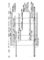
SIPTOのソリューション4(非特許文献1:5.5参照)では、UMTS(Universal Mobile Telecommunication Systems)マクロセルやHNBサブシステム(フェムトセル)に適用されるSIPTOとして、図19に示すような構成が開示されている。図19に示すように、RNC(Radio Network Controller)/HNBとSGSN(Serving GPRS(General Packet Radio System) Support Node)間にTOF(Traffic Offload)を備え、Giサブセットでインターネットとインタフェースする。なお、図19は、非特許文献1のFigure 5.5.2.1に基づく図である。図19において、TOFはIu−PSに備えられ、RNCとSGSNに標準のIu−PSインタフェースを提供する。Iuは、RNCとコアネットワーク(MSC(mobile Switching Center:移動交換局)又はSGSN)間のインタフェースであり、Iu−PSはRNCとパケット(Packet Switched)コアネットワーク間のインタフェースである。Giは、GGSN(Gateway GPRS Support Node)とPDN(Packet Data Network)間のインタフェースである。
In
Iu−PS上のTOFは、NAS(Non Access Stratum:非アクセス層)、RANAP(Radio Access Network Application Part)メッセージインスペクションを行い、加入者情報を取得し、ローカルUEオフロードコンテキストを確立する。またTOFは、PDP(Packet Data Protocol)コンテキスト情報を取得し、ローカルセッション・オフロードコンテキストを確立する。TOFは、上記情報に基づき、例えばアタッチとPDPアクティベーション手順中に、オフロードを行うか否かを決定する。オフロードにあたり、TOFは、GTP−U(GPRS Tunneling Protocol for User plane)トンネル(UEとGGSN間のトンネル)からアップリンクトラフィックを引き出し、例えばNAT(Network Address Translation)ゲートウェイ等でNATを実行し、トラフィックをオフロードする。ここで、NATは、ルータ等において、プライベートIPアドレスからグローバルIPアドレスへのアドレス変換を行う。あるいは、IPアドレスとTCP(transmission control protocol)/UDP(user datagram protocol)ポート番号をセットで変換する。またTOFは、ダウンリンクオフロードトラフィックに逆NATを施しGTP−Uトンネルに挿入して戻す。 The TOF on Iu-PS performs NAS (Non Access Stratum: Non Access Layer), Radio Access Network Application Part (RANAP) message inspection, obtains subscriber information, and establishes a local UE offload context. The TOF also obtains PDP (Packet Data Protocol) context information and establishes a local session offload context. The TOF determines whether to offload or not based on the above information, eg, during attach and PDP activation procedures. Upon offloading, TOF extracts uplink traffic from GTP-U (GPRS Tunneling Protocol for User plane) tunnel (tunnel between UE and GGSN), performs NAT with, for example, Network Address Translation (NAT) gateway, etc. Offload. Here, the NAT performs address conversion from a private IP address to a global IP address in a router or the like. Alternatively, the IP address and TCP (transmission control protocol) / UDP (user datagram protocol) port numbers are translated as a set. The TOF also reverse NATs the downlink offload traffic and inserts it back into the GTP-U tunnel.
このように、SIPTOのソリューション4は、ユーザ、APN、サービスタイプ、IPアドレス等に基づき、パケットインスペクションとNATによりオフロードを決定し、RNCとSGSN間のインタフェース(ユーザプレーン)であるIu−PSインタフェース上でデータトラフィックをオフロードする。なお、LTE(Long Term Evolution)には、ローカル・パケットデータネットワーク・ゲーウェイ(L−PGW(PDN(Packet Data Network) Gateway))の追加が必要である。
Thus,
SIPTOのソリューション5では(非特許文献1:5.6参照)、マクロセル、HNBに対応し、UMTS、LTEの両方に対応可能であり(また複数PDN接続に対応・非対応のUEに対応)、サービングゲートウェイSGW(RNC)と接続されるL−PGW(L−GGSN)を介して、インターネット等に接続する(非特許文献1のFigure 5.6.3.2 5.6.3.3、5.6.3.4参照)。なお、SGWはS−GWとも表記される。
あるいは、トラフィックを他のネットワークにオフロードさせる場合もある。例えばWi-Fi(Wireless Fidelity)接続機能を備えたスマートフォン、タブレット端末等の移動端末に対して、Wi-Fiアクセスポイント等、無線LAN(Wireless Local Area Network)等から、インターネットに接続させる(Wi-Fiオフロードともいう)。この場合、移動端末(UE)がWi-Fiアクセスポイントが設置された場所を外れると、通信接続できなくなる。すなわち、移動端末(UE)が移動時の接続性やセキュリティに問題がある。なお、無線LANが、PGW(PDN Gateway:P−GWとも表記される)、GGSNを介してPDNに接続される構成もある(非特許文献2:4.2参照)。 Alternatively, traffic may be offloaded to other networks. For example, a mobile terminal such as a smartphone or a tablet terminal having a Wi-Fi (Wireless Fidelity) connection function is connected to the Internet from a Wi-Fi access point, a wireless LAN (Wireless Local Area Network), etc. Also called Fi Off Road). In this case, when the mobile terminal (UE) leaves the place where the Wi-Fi access point is installed, communication connection can not be established. That is, there is a problem in connectivity and security when the mobile terminal (UE) moves. Note that there is also a configuration in which a wireless LAN is connected to a PDN via a PGW (PDN Gateway: also denoted as P-GW) and a GGSN (see Non-Patent Document 2: 4.2).
以下に関連技術の分析を与える。 The following gives an analysis of related technologies.
Wi-Fiオフロード等では、モビリティが実現できず、安全性等の点で問題がある。 In Wi-Fi off road etc, mobility can not be realized, and there are problems in terms of safety etc.
また、SIPTOのソリューション4等によるTOFではモビリティが実現できない。
In addition, mobility can not be realized with TOF using
上記した関連技術には、例えば移動端末で動作するアプリケーション等に応じてフロー単位にトラフィックオフロードを制御する点に関する開示はなく示唆もない。さらに、スマートフォン等高機能移動端末の増大に対して、移動端末のスケーラビリティに対応させたトラフィックオフロードを実現するための手法の実現が望まれる。 The related art described above does not disclose or suggest control of traffic offload on a flow basis in accordance with, for example, an application operating on a mobile terminal. Furthermore, it is desired to realize a method for realizing traffic offload in accordance with the scalability of mobile terminals in response to the increase of smart mobile terminals such as smart phones.
したがって、本発明は、上記問題点に鑑みて創案されたものであって、その主たる目的は、トラフィック増加によるネットワーク設備の増設を抑制し、トラフィックオフロードでのモビリティを実現するシステム、方法、装置、プログラムを提供することにある。 Therefore, the present invention has been made in view of the above problems, and its main object is to suppress the installation of network equipment due to an increase in traffic and to realize mobility on traffic offload. , To provide the program.
本発明によれば、第1のネットワークと第2のネットワーク間に配設されたスイッチ手段と、
前記第1のネットワークへのトラフィックのオフロードの有無を判定し、オフロードする場合、前記第1のネットワークを迂回するオフロード用の経路の設定を、前記スイッチ手段に対して行うオフロード判定手段と、
を備え、
前記第1のネットワークへのトラフィックのオフロード時に、オフロード対象のパケットは、前記オフロード用の経路と前記第2のネットワーク間を、前記スイッチ手段を介して転送される、システムが提供される。According to the invention, switch means disposed between the first network and the second network;
Offload determination means for determining the presence or absence of traffic offloading to the first network, and setting the offloading path for bypassing the first network to the switch means when offloading. When,
Equipped with
A system is provided in which, upon offloading of traffic to the first network, packets to be offloaded are transferred between the offloading path and the second network via the switch means. .
本発明の別の側面によれば、第1のネットワークへのトラフィックをオフロードさせるオフロード手段と、
前記第1のネットワークへのトラフィックのオフロードの指示を前記オフロード手段に対して行うオフロード判定手段と、
を備え、
前記オフロード手段は、前記オフロードの指示を受け、受信パケットに対してオフロードの有無を判断し、オフロード時には、前記パケットを、前記第1のネットワークを迂回するオフロード用の経路を転送する、システムが提供される。According to another aspect of the invention, an offload means for offloading traffic to a first network;
An offload determination unit for instructing the offload unit to offload traffic to the first network;
Equipped with
The offload unit receives the offload instruction, determines the presence or absence of offload for the received packet, and transfers the offload path for bypassing the first network at the offload time. The system is provided.
本発明のさらに別の側面によれば、第1のネットワークへのトラフィックのオフロードの有無を判定し、オフロードする場合、前記第1のネットワークを迂回するオフロード用の経路の設定を、前記第1のネットワークと第2のネットワーク間に配設されたスイッチ手段に対して行い、前記第1のネットワークへのトラフィックのオフロード時に、オフロード対象のパケットは、前記オフロード用の経路と前記第2のネットワーク間を、前記スイッチ手段を介して転送される方法が提供される。 According to still another aspect of the present invention, it is determined whether or not traffic is offloaded to a first network, and in the case of offloading, the setup of an offload route for bypassing the first network is The switch means disposed between the first network and the second network performs the offload target packet and the offload target packet at the time of the offload of traffic to the first network. A method is provided which is transferred between the second networks via the switch means.
本発明のさらに別の側面によれば、第1のネットワークへのトラフィックをオフロードさせるオフロード手段にて、オフロードの有無を判定するオフロード判定手段からのオフロードの指示を受けると、受信パケットに対してオフロードの有無を判断し、オフロード時には、前記パケットを、前記第1のネットワークを迂回するオフロード用の経路を転送する、方法が提供される。 According to still another aspect of the present invention, the offload means for offloading traffic to the first network receives the offload instruction from the offload determination means for determining the presence or absence of the offload. A method is provided for determining the presence or absence of an offload for a packet, and transferring the packet for an offload path bypassing the first network at the offload time.
本発明のさらに別の側面によれば、トラフィックのオフロード時に、オフロード経路の設定要求を、オフロード判定手段を備えたノードに送信し、受信パケットに対してオフロードの有無を判断し、オフロード時には、前記パケットを、コアネットワークを迂回するオフロード用の経路にパケットを転送する基地局装置が提供される。 According to still another aspect of the present invention, at the time of traffic offload, an offload path setting request is sent to a node provided with offload determination means, and it is determined whether or not the received packet is offloaded. At the time of offloading, a base station apparatus is provided which transfers the packet to an offloading path bypassing the core network.
本発明のさらに別の側面によれば、コアネットワークへのトラフィックのオフロードの指示を行うオフロード判定手段からのオフロード指示を受け、
受信パケットに対してオフロードの有無を判断し、オフロード対象のパケットを、前記コアネットワークを迂回するオフロード用の経路に転送する基地局装置が提供される。According to still another aspect of the present invention, there is provided an offload instruction from an offload determination means for instructing offload of traffic to the core network,
A base station apparatus is provided that determines the presence or absence of offloading for a received packet, and transfers the offload target packet to an offloading path bypassing the core network.
本発明のさらに別の側面によれば、第1のネットワークへのトラフィックをオフロードするオフロード手段からオフロード用の経路設定要求を受けると、前記第1のネットワークと第2のネットワークの間に接続するスイッチに対して、前記第1のネットワークを迂回して、前記第2のネットワークに接続するオフロード用の経路の設定を行う、制御装置が提供される。 According to still another aspect of the present invention, when an offload means for offloading traffic to a first network receives a routing request for offload from the offload means, a request between the first network and the second network is made. A control device is provided for the connecting switch, setting a path for offloading connected to the second network, bypassing the first network.
本発明のさらに別の側面によれば、第1のネットワークへのトラフィックをオフロードするオフロード手段からオフロード用の経路設定要求を受けると、前記オフロード手段に対してオフロード指示を送信し、前記オフロード手段では、受信したパケットがオフロード対象のパケットである場合、設定したオフロード用の経路へオフロードさせる、制御装置が提供される。 According to still another aspect of the present invention, an offload instruction is transmitted to the offload means when an offload means for offloading traffic to the first network receives a routing request for offload from the offload means. The offload means provides a control device for offloading to a set offload path when the received packet is a packet to be offloaded.
本発明のさらに別の側面によれば、基地局装置を構成するコンピュータに、
移動端末から無線ベアラを介して到着したパケットがオフロード対象に該当すると判断した場合、第1のネットワークを迂回するオフロード経路の接続要求を、直接又は第1のネットワークを経由して、前記第1のネットワークと第2のネットワーク間に配設されたスイッチに送信する処理と、
前記移動端末のモビリティを管理するノードから所定のコマンドを受けると、前記オフロード経路の切断要求を、前記スイッチに送信する処理と、を実行させるプログラムが提供される。本発明によれば、該プログラムを記録したコンピュータ読み出し可能な記録媒体(半導体メモリ、磁気ディスク/光ディスク)が提供される。According to still another aspect of the present invention, there is provided a computer configuring a base station apparatus,
If it is determined that the packet arrived from the mobile terminal via the radio bearer corresponds to the offload target, the connection request for the offload path bypassing the first network may be directly or via the first network. A process of transmitting to a switch disposed between the first network and the second network;
A program is provided that, upon receiving a predetermined command from a node managing mobility of the mobile terminal, a process of transmitting to the switch a request for disconnection of the offload path. According to the present invention, a computer readable recording medium (semiconductor memory, magnetic disk / optical disk) recording the program is provided.
本発明のさらに別の側面によれば、第1のネットワークと第2のネットワーク間に配設されたスイッチを制御する制御装置を構成するコンピュータに、
基地局装置から、前記第1のネットワークを迂回するオフロード経路の接続要求を、前記スイッチを介して受け取ると、前記基地局装置から前記オフロード経路に転送されたパケットを前記第2のネットワーク向けに転送し、且つ、前記第2のネットワークからのパケットを前記オフロード経路を介してノードに転送するように、前記スイッチに設定し、前記オフロード経路の接続要求に対する接続応答を前記基地局装置に返す処理と、
前記基地局装置から、前記オフロード経路の切断要求を、前記スイッチを介して受け取ると、前記第1のネットワークの関門ノードを前記第2のネットワークに接続するように前記スイッチに設定し、前記オフロード経路の切断要求に対する切断応答を前記基地局装置に返す処理と、を実行させるプログラムが提供される。本発明によれば、該プログラムを記録したコンピュータ読み出し可能な記録媒体(半導体メモリ、磁気ディスク/光ディスク)が提供される。
According to still another aspect of the present invention, there is provided a computer comprising a control device for controlling a switch disposed between a first network and a second network,
When a connection request for an offload path bypassing the first network is received from the base station via the switch, packets transferred from the base station to the offload path are directed to the second network. And the packet from the second network is transferred to the node via the offload path, set in the switch, and the connection response to the connection request for the offload path is the base station device And return to
When the disconnection request for the offload path is received from the base station apparatus via the switch, the switch node of the first network is set in the switch to connect to the second network, and the off is set. A program is provided which executes a process of returning a disconnection response to a load path disconnection request to the base station apparatus. According to the present invention, a computer readable recording medium (semiconductor memory, magnetic disk / optical disk) recording the program is provided.
本発明によれば、トラフィック増加によるモバイルネットワーク設備の増設等を抑制可能とし、トラフィックオフロードでのモビリティを実現している。 According to the present invention, it is possible to suppress the addition of a mobile network facility and the like due to the increase in traffic, and realize mobility on traffic off-load.
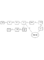
本発明の好ましい形態の一つについて説明する。図20(A)を参照すると、第1のネットワーク(NW1)と第2のネットワーク(NW2)間に配設されたスイッチ手段(SW)と、第1のネットワーク(NW1)へのトラフィックのオフロードの有無を判定し、オフロードする場合、第1のネットワーク(NW1)を迂回するオフロード用の経路の設定を前記スイッチ手段(SW)に対して行うオフロード判定手段を備えている。前記第1のネットワーク(NW1)へのトラフィックのオフロード時に、オフロード対象のパケットは、前記オフロード用の経路と前記第2のネットワーク(NW2)間を、前記スイッチ手段(SW)を介して転送される。第1のネットワーク(NW1)へのトラフィックをオフロードさせるオフロード手段は、トラフィックのオフロード時に、前記オフロード用の経路にパケットを転送する。前記オフロード用の経路に転送されたパケットは前記スイッチ手段(SW)を介して前記第2のネットワーク(NW2)に送信される。 One of the preferred embodiments of the present invention will be described. Referring to FIG. 20A, the switch means (SW) disposed between the first network (NW1) and the second network (NW2) and the offload of traffic to the first network (NW1) In the case of offload, it is provided with offload determination means for performing setting of an offload path for bypassing the first network (NW1) to the switch means (SW). At the time of offloading traffic to the first network (NW1), the offload target packet is transmitted between the offloading path and the second network (NW2) via the switch means (SW). To be transferred. An offloading means for offloading traffic to the first network (NW1) transfers a packet to the offloading path when the traffic is offloaded. The packet transferred to the offload path is transmitted to the second network (NW2) via the switch means (SW).
図20(A)において、第1のネットワーク(NW1)へのトラフィックオフロード時に、オフロード手段は、オフロード判定手段に対して、オフロード経路設定要求を送信する。オフロード判定手段は、オフロード経路設定要求に応答して、オフロード用の経路の設定を、第1と第2のネットワーク間のスイッチ(SW)に対して行う。これにより、オフロード手段と第2のネットワーク(NW2)間は、オフロード経路とスイッチ手段(SW)を介して接続され、移動端末と第2のネットワーク(NW2)間で送受されるパケットは、第1のネットワーク(NW1)を迂回する前記オフロード用の経路上を転送される。第1のネットワーク(NW1)と、第2のネットワーク(NW2)とは、一例として、それぞれ、コアネットワーク(Core Network:CN)と、パケットデータネットワーク(Packet Data Network:PDN)としてもよい。本実施形態において、オフロード判定手段、オフロード手段は、例えばオープンフローコントローラ(OFC)、オフロード機能付き基地局にそれぞれ実装してもよい。あるいは、オフロード判定手段は、移動端末のモビリティを管理するノードであるMME(Mobility Management Entity)やSGSN等に実装してもよい。この場合、オフロード手段を、オフロード機能付き基地局、あるいは、SIPTOゲートウェイ等に実装してもよい。なお、本発明において、オフロード判定手段とオフロード手段を別々のノードに実装する構成に制限されるものでないことは勿論である。例えば、実施形態の変形例として、オフロード判定手段、オフロード手段を一体化して、1つのネットワークノード、例えば基地局に実装するようにしてもよい。 In FIG. 20A, at the time of traffic offloading to the first network (NW1), the offloading means transmits an offload route setting request to the offloading determination means. The offload determination means performs, in response to the offload path setting request, setting of the offload path for the switch (SW) between the first and second networks. Thus, the offload unit and the second network (NW2) are connected via the offload path and the switch unit (SW), and packets transmitted and received between the mobile terminal and the second network (NW2) are It is transferred on the offload path which bypasses the first network (NW1). The first network (NW1) and the second network (NW2) may be, for example, a core network (CN) and a packet data network (PDN), respectively. In the present embodiment, the offload determination unit and the offload unit may be implemented, for example, in an open flow controller (OFC) and a base station with an offload function. Alternatively, the offload determination means may be implemented in an MME (Mobility Management Entity), an SGSN, or the like, which is a node that manages the mobility of the mobile terminal. In this case, the offload means may be implemented in a base station with an offload function, a SIPTO gateway, or the like. Of course, the present invention is not limited to the configuration in which the offload determination means and the offload means are mounted on different nodes. For example, as a modification of the embodiment, the offload determination means and the offload means may be integrated and implemented in one network node, for example, a base station.
別の形態において、図20(B)を参照すると、第1のネットワーク(NW1)へのトラフィックをオフロードさせるオフロード手段と、第1のネットワーク(NW1)へのトラフィックのオフロードの指示を、前記オフロード手段に対して行うオフロード判定手段とを備えている。前記オフロード手段は、前記オフロードの指示を受け、受信パケットに対してオフロードの有無を判断し、オフロード対象の前記受信パケットを、第1のネットワーク(NW1)を迂回するオフロード用の経路に転送する。本実施形態において、オフロード手段は、オフロード判定手段に対して、オフロード経路設定要求を送信する。オフロード判定手段は、オフロードの指示を、オフロード手段に対して通知する。また、オフロード判定手段は、第1のネットワーク(NW1)を迂回する前記オフロード用の経路の設定を、第1のネットワーク(NW1)と第2のネットワーク(NW2)間のスイッチ手段(SW)に対して行う。これにより、前記オフロード手段と前記第2のネットワーク(NW2)間は、前記オフロード経路と前記スイッチ手段(SW)を介して接続される。 In another form, referring to FIG. 20 (B), an offloading means for offloading traffic to the first network (NW1) and an instruction for offloading traffic to the first network (NW1), And an offload determination means for performing the offload means. The offload means receives the offload instruction, determines the presence or absence of the offload for the received packet, and is for the offload for diverting the received packet to be offloaded to the first network (NW1). Transfer to the route. In the present embodiment, the offload means transmits an offload path setting request to the offload determination means. The offload determination means notifies an offload instruction to the offload means. Further, the offload determination means sets the offload path for bypassing the first network (NW1) as a switch means (SW) between the first network (NW1) and the second network (NW2). Do against Thus, the offload means and the second network (NW2) are connected via the offload path and the switch means (SW).
本発明のいくつかの実施形態によれば、コアネットワーク(CN)へのトラフィックをオフロードさせる機能を備えたノード(例えば図1の102、図15の124、図16の133)と、前記コアネットワークの関門ノード(例えば図1、図16のS/P−GW(SGW/PGW)103のPGW(PDN Gateway)、図15のPGW103P)と外部パケットデータネットワーク(図1、図15、図16のPDN104)間に配設されたスイッチ(OFS)(図1、図15、図16の105)とを備えている。トラフィックのオフロード時には、前記スイッチ(OFS)は、前記ノード(例えば図1の102、図15の124、図16の133)を、前記コアネットワーク迂回用のオフロード経路(図1の107、図15の107、127、図16の137)を介して前記外部パケットデータネットワーク(図1、図15、図16の104)に接続する。非オフロード時には、前記ノード(例えば図1の102、図15の124、図16の133)は、前記コアネットワーク(CN)に接続し、前記スイッチは、前記コアネットワーク(CN)の関門ノード(例えば図1、図16のS/P−GW103のPGW、図15のPGW103P)を前記外部パケットデータネットワーク(図1、図15、図16のPDN104)に接続する。さらに、後に詳説されるように、いくかの形態によれば、前記オフロード機能付基地局間での基地局間ハンドオーバ、さらに、オフロード機能付基地局を移動元/移動先とし、オフロード機能を具備しない基地局を移動先/移動元とする基地局間ハンドオーバを実現する手段を提供している。なお、ここで、パケットは、データ列の単位に対応しており、例えばレイヤ3(ネットワーク層)のパケット、レイヤ2(データリンク層)の場合のフレーム等を含む。
According to some embodiments of the present invention, a node (e.g. 102 in FIG. 1, 124 in FIG. 15, 133 in FIG. 16) with the function of offloading traffic to a core network (CN); The gateway node of the network (for example, PGW (PDN Gateway) of S / P-GW (SGW / PGW) 103 in FIG. 1, FIG. 16;
<実施形態1>
本発明の一実施形態について図1を参照して説明する。なお、図1は、図20(A)を参照して説明した形態に対応し、第1、第2のネットワークを、それぞれ、コアネットワーク、PDN(Packet Data Network)としている。この実施形態によれば、PDN(Packet Data Network)104とPGW間の参照ポイント(RP: Reference Point)であるSGi(2G/3G(第2/3世代)ではPDNとGGSN間の参照ポイントであるGi)に対応させてスイッチ(OFS)105を配置し、トラフィックオフロード(TOF)時には、移動端末101からのアップリンクデータトラフィックは、無線アクセスネットワーク(RAN:Radio Access Network)のトラフィックオフロードノードでオフロードされ、コアネットワーク(CN:例えばLTE/EPC(Long Term Evolution/Evolved Packet Core)ネットワーク)を迂回して、スイッチ105を介して、PDN104に転送される。無線アクセスネットワーク(RAN)のトラフィックオフロードノードは、例えばE−UTRAN(Evolved Universal Terrestrial Random Access Network)の場合、TOF機能付eNB(evolved Node B)(図1の102)、UTRAN(Universal Terrestrial Random Access Network)の場合、例えば、前述したIu−PS上のTOF(図15の124))である。PDN104からのダウンリンクトラフィックは、該スイッチ105から、コアネットワーク(CN)を迂回して、無線アクセスネットワーク(RAN)のトラフィックオフロードノードに転送され、移動端末101に無線送信される。なお、非オフロード時には、移動端末101からのアップリンクデータトラフィックは、無線アクセスネットワーク(RAN)、コアネットワーク(CN)、該スイッチ105を介してPDN104に転送される。またPDN104からのダウンリンクトラフィックは該スイッチ105からコアネットワーク(CN)、無線アクセスネットワーク(RAN)を介して移動端末101に送信される。
First Embodiment
One embodiment of the present invention will be described with reference to FIG. Note that FIG. 1 corresponds to the mode described with reference to FIG. 20A, and the first and second networks are a core network and a packet data network (PDN), respectively. According to this embodiment, in SGi (2G / 3G (2/3 generation)), which is a reference point (RP: Reference Point) between PDN (Packet Data Network) 104 and PGW, it is a reference point between PDN and GGSN. Switch (OFS) 105 is arranged corresponding to Gi), and at the time of traffic offload (TOF), uplink data traffic from
本発明の一実施形態において、スイッチ105はオープンフロースイッチ(OFS)で構成される。さらに、前記オープンフロースイッチ(OFS)を制御するオープンフローコントローラ106を備えている。オープンフローコントローラ106は、トラフィックオフロード時のフローを、オープンフロースイッチ(OFS)のフローテーブルに設定する。なお、オープンフロースイッチ(OFS)のフローテーブルに設定されるフローは、非オフロード時の経路(PGW)をデフォルト値としてもよい。
In one embodiment of the present invention,
<オープンフロー>
以下では、オープンフロー(Open Flow)について概説しておく。OpenFlowは、OpenFlowスイッチコンソーシアムが提唱した、ネットワーク制御技術のことであり、物理ポート番号(L1)、MAC(Media Access Control)アドレス(L2)やIPアドレス(L3)、ポート番号(L4)などの識別子の組み合わせによって決定される一連の通信を「フロー」として定義し、フロー単位での経路制御を実現する。転送ノードとして機能するオープンフロースイッチ(OpenFlow Switch:OFSと略記される)は、オープンフローコントローラ(OpenFlow Controller:OFCと略記される)から追加又は書き換えを指示されるフローテーブルに従って動作する。フローテーブルには、フロー毎に、ルール(パケットのヘッダ情報と照合されるフィルタリング条件)、統計情報(カウンタとして指定できる。パケット数、バイト数、フローがアクティブな期間等のフロー統計情報を含む)、ルールにマッチしたパケットに対して適用する処理を規定したアクション(フロー処理、パケット転送(Forward)、廃棄(Drop)、パケットの特定のフィールドを書き換える(Modify-Field)の修正等)を含む。パケット転送(Forward)には、例えば
・スイッチの特定のポートへの転送、
・スイッチの全てのポートへの転送、
・OFCに転送等
が選択される。<Open flow>
The following outlines the Open Flow. OpenFlow is a network control technology advocated by the OpenFlow switch consortium, and identifiers such as physical port number (L1), MAC (Media Access Control) address (L2), IP address (L3), port number (L4), etc. A series of communications determined by the combination of are defined as "flow" to realize path control on a flow basis. An open flow switch (abbreviated as OpenFlow Switch: OFS) functioning as a forwarding node operates in accordance with a flow table instructed to be added or rewritten from an open flow controller (abbreviated as OpenFlow Controller: OFC). In the flow table, for each flow, rules (filtering conditions to be checked against packet header information), statistical information (can be specified as a counter, including flow statistical information such as number of packets, number of bytes, period of active flow, etc.) And an action (flow processing, packet forwarding (Forward), discard (Drop), modification of a specific field of a packet, etc.) for defining a process to be applied to a packet matching a rule (Modify-Field). For packet forwarding (Forward), eg forwarding to a specific port of the switch,
• Forwarding to all ports on the switch,
• Transfer to the OFC is selected.
OFSは、パケットを受信すると、OFS内のフローテーブルを検索し、パケットのヘッダ情報と、ルールとのマッチ(照合)を行う。照合されるヘッダフィールドとしてレイヤ1(L1)からレイヤ4(L4)の任意の組み合わせを使うことができる。その一例を以下に示す。 When the OFS receives a packet, the OFS searches the flow table in the OFS to match (match) the packet header information with the rule. Any combination of layer 1 (L1) to layer 4 (L4) can be used as the header field to be matched. An example is shown below.
L1:Ingress Port(スイッチの物理ポート番号);
L2:Ether src(送信元MACアドレス)、Ether dst(宛先MACアドレス)、Etherタイプ、VLAN(Virtual Local Area Network)-id、VLANプライオリティ;
L3:IP src(送信元IPアドレス)、IP dst(宛先IPアドレス)、IPプロトコル種別、TOS(Type Of Service)値;
L4:TCP(Transmission Control Protocol)/UDP(User Datagram Protocol) src port(送信元L4ポート番号)、TCP/UDP dst port(宛先L4ポート番号)L1: Ingress Port (physical port number of switch);
L2: Ether src (source MAC address), Ether dst (destination MAC address), Ether type, VLAN (Virtual Local Area Network) -id, VLAN priority;
L3: IP src (source IP address), IP dst (destination IP address), IP protocol type, TOS (Type Of Service) value;
L4: Transmission Control Protocol (TCP) / User Datagram Protocol (UDP) src port (transmission source L4 port number), TCP / UDP dst port (destination L4 port number)
受信したパケットのヘッダ情報が、あるフローエントリのルール(条件)にマッチする場合、当該ルールに対応するアクション(当該フローエントリのアクション欄)に定義された処理(当該ルールがマッチしたときにパケットに対して実行される処理)を実行する。フローテーブルを検索した結果、受信したパケットのヘッダ情報にマッチするルールを有するフローエントリが見つからなかった場合、OFSは、OFCへセキュアチャネルを用いて受信パケットを転送する。OFCは、前記受信パケットの送信元・送信先情報に基づき、経路計算を行い、受信パケットの転送経路を決定し、転送経路上の全てのOFSに対して、決定した転送経路を実現するためにフローテーブルを設定する(フローセットアップ)。該フローセットアップを行ったOFCは、受信パケットを例えばフローの出口となるOFSに転送し、前記フローの出口となる前記OFSを介して送信先に送信する。以降、前記受信パケットと同じフローに属するパケットのヘッダ情報は、前記フローセットアップが行われたOFSのフローテーブル内のルールにマッチし、設定されたフローテーブル(ルールとアクション)に従って、前記パケットの転送経路上の各OFSを転送され、送信先端末に送られる。OFSでフローテーブルを検索した結果、マッチしないパケットは、あるフローの最初に転送されるパケットである場合が多い。このようなパケットは、総称して「ファーストパケット」ともいう。 When header information of a received packet matches a rule (condition) of a certain flow entry, processing (defined as the rule matches) defined in an action (action column of the relevant flow entry) corresponding to the rule Execute the process to be executed). As a result of searching the flow table, if no flow entry having a rule matching the header information of the received packet is found, the OFS transfers the received packet to the OFC using the secure channel. The OFC performs route calculation based on the source / destination information of the received packet, determines the transfer route of the received packet, and implements the determined transfer route for all the OFSs on the transfer route. Set the flow table (flow setup). The OFC that has performed the flow setup transfers the received packet, for example, to the OFS that is the exit of the flow, and transmits the received packet to the destination via the OFS that is the exit of the flow. Thereafter, header information of a packet belonging to the same flow as the received packet matches the rule in the flow table of the OFS for which the flow setup has been performed, and the packet is forwarded according to the set flow table (rule and action) Each OFS on the path is forwarded and sent to the destination terminal. As a result of searching the flow table with the OFS, the unmatched packet is often the packet transferred at the beginning of a certain flow. Such packets are also collectively referred to as "first packets".
図2は、本発明の一実施形態を例示する図である。移動端末(UE)(User Equipment)101と、サービス圏内のUE101に無線リンクで接続し、トラフィックのオフロード機能を備えた基地局eNB(eNode B)(オフロード機能付き基地局eNBは、「eNB+TOF」とも略記される)102と、局舎110を備えている。局舎110は、S/P−GW103、OFS105、OFC106、認証(Authentication)、認可(Authorization)、課金(Accounting)を制御するAAAサーバとして機能するRADIUS(Remote Authentication Dial In User Service)サーバ108、レイヤ3で中継制御を行うルータ109を備え、ルータ109はPDN104に接続されている。ルータ109は中継に際してMACアドレスを終端し、該ルータが送出するMACフレームは、該ルータ109のポートのMACアドレスとなる。図2において、MME(Mobility Management Entity)、HSS(Home Subscriber Server)、PCRF(Policy and Charging Rules Function)等は省略されている。図2において、特に制限されないが、レイヤ2スイッチ(L2SW)を、局舎110に対して1つ下の階層の地方局舎(オフロード機能を備えた基地局(eNB+TOF)102と局舎110の間)に配置してもよい。なお、図2では、簡単のため、ルータ109近傍のOFS105には1つのPGWが接続されているが、レイヤ2スイッチとして機能するOFSに複数のPGWを接続する構成とし、スケーラブルなシステム構成(加入者増大/縮小、負荷増大/縮小に対応してシステムの拡張/縮減)としてもよいし、冗長構成としてもよい。OFSを用いたことで、ネットワークのスケーラビリティの向上を容易化している。
FIG. 2 is a diagram illustrating an embodiment of the present invention. A base station eNB (eNode B) (a base station eNB with an offload function) that is connected to a mobile terminal (UE) (User Equipment) 101 and a
OFC106は、オフロード機能付基地局(eNB+TOF)102からの通知でUE101毎のオフロード経路107を追加し(図2のeNB+TOF102とOFS105間の経路107)、OFS105に設定する。OFS105は、オフロード時は、OFC106からセットアップされたフローテーブル(フロー毎に設定されたルールとアクション)に従い、オフロード機能付きの基地局(eNB+TOF)102でオフロードされたアップリンクパケットをルータ109に転送してPDN104に送信し、PDN104からルータ109を介して転送されたダウンリンクパケットをオフロード機能付きの基地局(eNB+TOF)102に転送する。OFS105は、非オフロード時は、OFC106からセットアップされたフローテーブルに従い、オフロード機能付きの基地局(eNB+TOF)102からS/P−GW103に転送されたアップリンクパケットをルータ109に転送してPDN104に送信し、PDN104からルータ109を介して転送されたダウンリンクパケットをS/P−GW103を介してオフロード機能付きの基地局(eNB+TOF)102に転送する。図2において、RADIUSサーバは例えばPGWと接続して認証を行うが、同時にOFS105にも接続されている。これは、後述するように、OFS105が、PGWとRADIUSサーバ間で転送されるパケットをフックして、OFC106に転送することを模式的に示している。また図1、図2では、単に簡単のために、SGW(Serving Gateway)とPGWは一体に収容した構成として示しているが、SGWとPGWとは互いに別々に配置してもよいことは勿論である。
The
この実施形態によれば、例えば移動端末(UE)101でのWeb閲覧、メールの取得、Tweet、決済、動画閲覧等、アプリケーション毎に応じて、ネットワークを選択可能としている。OFC106では、フロー単位で通信網を選択することで、UE101が通信サービスを受ける場合等において、最適な通信ネットワークの利用を可能としている。
According to this embodiment, for example, the network can be selected according to each application such as Web browsing on the mobile terminal (UE) 101, acquisition of mail, Tweet, settlement, moving image browsing, and the like. In the case where the
特に制限されないが、以下では、
無線アクセスネットワーク(RAN)をE−UTRAN、
コアネットワーク(CN)をEPC/LTEネットワーク、
とした場合の適用例を説明する。図3は、図1、図2の構成の一例を例示した図である。図3において、図1、図2と同一の要素には同一の参照符号が付されている。以下、各要素を概説しておく。eNB102aは、S1−UインタフェースによりSGWに接続され、S1−MMEインタフェースによりMMEに接続される。Although not particularly limited, in the following,
Radio Access Network (RAN) E-UTRAN,
EPC / LTE network, core network (CN),
An application example in the case of FIG. 3 is a diagram illustrating an example of the configuration of FIG. 1 and FIG. In FIG. 3, the same elements as in FIGS. 1 and 2 are assigned the same reference numerals. The following outlines each element. The
基地局102−1、102−2は、上記eNB102aに、本発明に従いトラフィックオフロード(TOF)機能を具備したものであり、前述したように、eNB+TOFと表記される。
The base stations 102-1 and 102-2 are provided with the traffic offload (TOF) function according to the present invention in the above-mentioned
S/P−GW103のSGW(Serving Gateway)は、ユーザデータパケットをルーチングして転送し、同時に、eNB間ハンドオーバ中のユーザプレーンのモビリティアンカとして機能する。SGWはLTEと他の3GPP技術の間のモビリティのためのアンカとして機能する(例えばS4インタフェースを終了させ、2G/3GシステムとPGWとの間のトラフィックを中継する)。アイドル状態のUEでは、SGWはダウンリンクデータパスを終了し、ダウンリンクデータが到達したときに、ページングをトリガする。SGWは、UEのコンテキスト(例えばIPベアラサービスのパラメータや、ネットワーク内部ルーティング情報等)を管理及び保存する。
The SGW (Serving Gateway) of the S / P-
MME(Mobility Management Entity)112は、LTEアクセスネットワークにおいて、移動端末(UE)のモビリティ管理ノードとして機能し、例えば、アイドルモードの移動端末(UE)のトラッキング、ページング、ベアラの活性化、非活性化、初期アタッチ時点でのSGW、PGWの選択、SGW、PGW間のトンネル確立の管理、LTE内ハンドオーバ時の移動端末(UE)用のSGWの選択、HSSと連携したユーザ認証等を行う。MMEは、メッセージ交換のためのS1−AP(アプリケーション)プロトコルを適用するS1−MMEインタフェースを介して基地局(eNB)に接続される。さらに、MME112はS11インタフェースを介してSGWに接続される。
An MME (Mobility Management Entity) 112 functions as a mobility management node of a mobile terminal (UE) in the LTE access network, for example, tracking, paging, bearer activation, and deactivation of a mobile terminal (UE) in idle mode. Selection of SGW and PGW at initial attach time, management of tunnel establishment between SGW and PGW, selection of SGW for mobile terminal (UE) at handover in LTE, user authentication in cooperation with HSS, etc. The MME is connected to the base station (eNB) via an S1-MME interface applying an S1-AP (application) protocol for message exchange. Furthermore, the
S/P−GW103のPGW(PDN Gateway)は、外部PDNへの移動端末(UE)の接続を実現する。移動端末(UE)は複数のPDNにアクセスするための2つ以上のPGWとの接続性を同時に有することができる。PGWはトラフィックを適切なQoS(Quality of Service)レベルにマッピングするために、アタッチした移動端末(UE)に対して、例えばIPアドレスの割り当て(払い出し)、ポリシ適用、パケットフィルタリング(例えばディープパケットインスペクション、パケットスクリーニング)を実行する。なお、図3では、SGWとPGWを一体に備えた構成が開示されているが、別々に配置してよいことは勿論である。PGWは、PGWとSGWが同じPLMN(Public Land Mobile Network)に位置している場合には、S5インタフェースを介してSGWに接続され、SGWが外部の(在圏)PLMNに位置している場合には、S8インタフェースを介してSGWに接続される。
The PGW (PDN Gateway) of the S / P-
PCRF(Policy and Charging Rules Function)113は、ポリシ及び課金規則を制御する。PCRF113は、PGWとS7インタフェースで接続される。
Policy and Charging Rules Function (PRRF) 113 controls policy and charging rules. The
HSS(Home Subscriber Server)/AAA(Authentication, Authorization and Accounting)114は、加入者情報の管理、及び認証を行う。HSSサーバとAAAサーバを別に配置してもよい。図3のAAAサーバは、図2のRADIUSサーバ108であってもよい。図5以降の動作説明図では、RADIUSとして示される。
Home Subscriber Server (HSS) / Authentication, Authorization and Accounting (AAA) 114 manages and authenticates subscriber information. The HSS server and the AAA server may be separately arranged. The AAA server of FIG. 3 may be the
図3に示す構成例では、PGWとPDN間のインタフェースSGiとして、SGi1、SGi2の2セットを備え、それぞれに対応してOFS1、OFS2が配設されている。さらに、OFS1、OFS2にそれぞれ接続され、OFS1、OFS2をそれぞれ制御するOFC1、OFC2を備えている。OFS1、OFS2は、それぞれ、ルータ109−1、ルータ109−2を介して、PDN104に接続される。なお、PDN104のサーバ104−1はWebサーバ等であってもよいし、OpenFlowベースのトラフィックオフロード機能の接続性等をテストし、各種設定を行うテストサーバ等であってもよい。
In the configuration example shown in FIG. 3, two sets of SGi1 and SGi2 are provided as the interface SGi between PGW and PDN, and OFS1 and OFS2 are arranged corresponding to each. Furthermore, OFC1 and OFC2 connected to OFS1 and OFS2 and respectively controlling OFS1 and OFS2 are provided. The
図3において、eNB102−1、102−2と、OFS1、OFS2間に、レイヤ2スイッチ(L2SW)111、111−2を介して接続されるパス(eNB102−1、102−2に接続する破線をそれぞれ一点鎖線、二点鎖線で示す)が、S/P−GW103を迂回するオフロード経路を表している。OFC1は、PCRF113に接続され、オフロード処理されたパケットカウント等を課金情報として通知する。OFC2も同様の処理を行う。なお、OFSを導入するSGi毎に、OFC〜OFS〜MBH(Mobile Back Haul:基地局とコアネットワークを接続する)〜基地局(eNB+TOF)に、VLAN(Virtual LAN)を追加し(図3の一点鎖線、二点鎖線、破線等で示す)、同一のSGiに接続するVLANを分けるようにしてもよい。例えばVLAN毎に異なるIPアドレス空間を割当てる。この場合、基地局は複数のIPアドレスを持つ。例えば、VLANに割当てられるIPアドレス空間が、一点鎖線で示すVLAN:192.168.0.0/22、破線で示すVLAN:192.168.4.0/22、二点鎖線で示すVLAN:192.168.8.0/22である場合、eNB102−1には、例えばIPアドレス192.168.0.10と192.168.4.10が割り当てられる。
In FIG. 3, a path (a dashed line connected to eNBs 102-1 and 102-2 is connected between eNBs 102-1 and 102-2 and
なお、図3において、レイヤ2スイッチ(L2SW)111とS/P−GW103間のルータ115は削除してもよい。ルータ115は、レイヤ2スイッチ(L2SW)111に接続する基地局群を、図示されない他のS/P−GWへルーチングする。また、レイヤ2スイッチ(L2SW)111−2は削除してもよい。図3において、OFC1、OFS1、OFC2、OFS2は同一のIPアドレスを有している。SGi1、SGi2がそれぞれOFS1、OFS2に接続されている。なお、アドレスの重複等がない場合、1つのOFSに複数のPGWを接続する構成としてもよい。また、OFCに接続されるOFSは簡単のため1つが示されているが、同一のOFCに複数のOFSを接続する構成としてもよいことは勿論である。またレイヤ2スイッチ(L2SW)111、111−2をOFSで構成してもよいことは勿論である。
In FIG. 3, the router 115 between the
次に、図3を参照して説明した実施形態の動作について図4から図14のそれぞれの図を参照して説明する。なお、LTEでは、移動端末(UE)と基地局(eNB)の接続状態は、RRC(Radio Resource Control)のアイドル(RRC idle)と、接続状態(RRC connected)がある。UEとコアネットワーク(MME)との接続状態は、ECM(EPS(Evolved Packet System) Connection Management)アイドル(ECM Idle)と、ECM接続状態(ECM Connected)がある。なお、UEアドレスには、IPv4でのIPアドレス枯渇のため、プライベートIPアドレスが用いられる。同一の基地局が、重複するプライベートアドレス空間を持つEPCにつながらない(プライベートアドレスが重複しない)。 Next, the operation of the embodiment described with reference to FIG. 3 will be described with reference to the respective drawings of FIG. 4 to FIG. In LTE, the connection state of the mobile terminal (UE) and the base station (eNB) includes idle (RRC idle) of RRC (Radio Resource Control) and a connected state (RRC connected). The connection state between the UE and the core network (MME) includes ECM (Evolved Packet System) Connection Management (EPS) Idle (ECM Idle) and ECM connected state (ECM Connected). As the UE address, a private IP address is used for exhaustion of the IP address in IPv4. The same base station does not connect to an EPC with overlapping private address spaces (private addresses do not overlap).
図4は、UE(図2の101)のネットワークへの登録処理(アタッチ処理)時の動作手順(シーケンス)を説明する図である。図4において、eNBは図3のeNB102aに対応し、eNB+TOF1、eNB+TOF2は、図3のオフロード機能付きの基地局(eNB+TOF1)102−1、オフロード機能付きの基地局(eNB+TOF2)102−2にそれぞれ対応する。RADIUSは図2の108、ルータ(Router)は、図2の109、図3の109−1又は109−2に対応する。図5から図14のそれぞれについても同様である。
FIG. 4 is a diagram for explaining an operation procedure (sequence) at the time of registration processing (attach processing) to the network of the UE (101 in FIG. 2). In FIG. 4, eNB corresponds to eNB 102 a in FIG. 3, and eNB +
UEからのベアラ確立要求(アタッチリクエスト)で、UEとS/P−GW間でベアラを確立する(1)。なお、手順(1)のベアラ確立処理では、UEはアタッチ要求メッセージをMMEへ送信する。MMEは、加入者情報を登録したHSSから取得した認証情報を基にユーザ認証を行い、UEが前記アタッチ要求メッセージで通知したAPN(Access Point Name)を基に、SGW、PGWを選択し、選択したSGW、PGWに対してベアラ設定要求を送信する。PGWは、IPアドレスの払い出しを行い、さらにSGW、PGW間のベアラを設定する。SGWは、MMEにベアラ設定応答を返す。MMEは、eNBに対してコンテキスト設定要求を送信し、UEとeNB間の無線ベアラを設定する。UEは、アタッチ完了応答をMMEに送信する。eNBは、MMEに対して、コンテキスト設定応答を返す。MMEは、コンテキスト設定応答に基づき、ベアラ更新要求をSGWに送信し、SGWはベアラ更新応答をMMEに返す。 In a bearer establishment request (attach request) from the UE, a bearer is established between the UE and the S / P-GW (1). In the bearer establishment process of procedure (1), the UE transmits an attach request message to the MME. The MME performs user authentication based on the authentication information acquired from the HSS that has registered subscriber information, and selects and selects SGW or PGW based on the APN (Access Point Name) notified by the UE in the attach request message. The bearer setting request is transmitted to the selected SGW and PGW. The PGW issues an IP address, and sets a bearer between the SGW and the PGW. The SGW returns a bearer setting response to the MME. The MME transmits a context setting request to the eNB, and sets a radio bearer between the UE and the eNB. The UE sends an attach complete response to the MME. The eNB returns a context setting response to the MME. The MME transmits a bearer update request to the SGW based on the context setting response, and the SGW returns a bearer update response to the MME.
図4に示すように、OFC(図2の106)は、認証を行うRADIUSサーバ(図2の108)の中継ノードとして機能する。すなわち、OFS(図2の105)は、RADIUSクライアントであるアクセスポイント(例えばPGW)からRADIUSサーバへ転送される要求パケットをフックする(2)。その際、OFS(図2の105)は、RADIUSサーバへ転送される要求パケットを、例えばフィルタリングして取り込む。OFS(図2の105)において、該要求パケットは、もともと、RADIUSサーバ宛のパケットであり、当該パケットのヘッダ情報は、当該OFSのフローテーブルのルールとマッチしないため、該要求パケットは、例えば「ファーストパケット」としてセキュアチャネルを用いて、OFCに転送される(3)。該要求パケットは、OFCから再びOFSを介してRADIUSサーバに転送される(4、5)。あるいは、該要求パケットをOFSからOFCに転送するようにフローテーブルを設定するようにしてもよい(この場合、セキュアチャネルは用いられない)。 As shown in FIG. 4, the OFC (106 in FIG. 2) functions as a relay node of the RADIUS server (108 in FIG. 2) that performs authentication. That is, the OFS (105 in FIG. 2) hooks (2) a request packet transferred from the access point (eg, PGW) which is the RADIUS client to the RADIUS server. At that time, the OFS (105 in FIG. 2) takes in, for example, filtering the request packet transferred to the RADIUS server. In the OFS (105 in FIG. 2), the request packet is originally a packet addressed to the RADIUS server, and the header information of the packet does not match the rule of the flow table of the OFS, so the request packet is It is transferred to the OFC using a secure channel as a "first packet" (3). The request packet is forwarded from the OFC to the RADIUS server again via the OFS (4, 5). Alternatively, the flow table may be set to transfer the request packet from the OFS to the OFC (in this case, a secure channel is not used).
RADIUSクライアントであるPGWからRADIUSサーバへのRADIUS要求パケット(UDP(User Datagram Protocol))には、例えばユーザ名、暗号化パスワード、クライアントのIPアドレス、ポートIDが含まれる。RADIUSサーバは、認証要求を受信すると、ログイン要求と一致するユーザデータベースを調べる。RADIUSサーバはユーザの接続要求、認証を行い、必要な設定情報等を応答として返す。 The RADIUS request packet (UDP (User Datagram Protocol)) from the PGW, which is a RADIUS client, to the RADIUS server includes, for example, a user name, an encrypted password, an IP address of the client, and a port ID. When the RADIUS server receives the authentication request, it looks up the user database that matches the login request. The RADIUS server makes a connection request for the user, performs authentication, and returns necessary setting information and the like as a response.
RADIUSサーバからPGWへの応答パケットもOFCでフックされ(6)、OFC(図2の106)に転送される(7)。OFC(図2の106)ではパケットインスペクションを行い、端末ID(IMSI(International Mobile Subscriber Identity))、IPアドレス、VLAN(Virtual Local Area Network)の対応関係を記録する(8)。なお、VLANは、ポートベース(レイヤ2スイッチの各ポート毎にグルーピングを行う)、MACアドレスベース(MACアドレス毎にVLANを決定する)、あるいはプロトコルベース等により、接続ノードのグループ化が行われる。
The response packet from the RADIUS server to the PGW is also hooked with the OFC (6) and forwarded to the OFC (106 in FIG. 2) (7). The OFC (106 in FIG. 2) performs packet inspection and records the correspondence between the terminal ID (IMSI (International Mobile Subscriber Identity)), the IP address, and the VLAN (Virtual Local Area Network) (8). Note that grouping of connected nodes is performed on a port basis (grouping is performed for each port of the
RADIUSサーバからの該応答パケットは、OFC(図2の106)、OFS(図2の105)を介してPGWに転送される(9、10)。なお、RADIUSサーバとRADIUSクライアント(PGW)間では共通鍵方式で詐称、改竄を防いでいる。このため、OFCは、RADIUSサーバと共通の鍵情報を保持する。RADIUSサーバをAAAサーバとして配置した場合、PGWはRADIUSサーバと例えばS6cインタフェースで接続される。 The response packet from the RADIUS server is forwarded (9, 10) to the PGW via the OFC (106 in FIG. 2), the OFS (105 in FIG. 2). In addition, between the RADIUS server and the RADIUS client (PGW), spoofing and tampering are prevented by the common key method. Therefore, the OFC holds key information common to the RADIUS server. When the RADIUS server is arranged as an AAA server, the PGW is connected to the RADIUS server via, for example, the S6c interface.
その後、PGWは、IPアドレスを払い出し、該IPアドレスをUEに通知する(11)。 Thereafter, the PGW issues an IP address and notifies the UE of the IP address (11).
<オフロード経路の追加>
図5は、UEが、オフロード機能付き基地局(eNB+TOF)の配下で通信を開始した場合の動作(オフロード経路の追加)を説明する図である。なお、前提として、異なるSGiに接続するOFS(OFC)のプライベートアドレスは重複しないものとする(例えば同一の基地局が、重複するプライベートアドレス空間を持つEPCには繋がらない場合である)。<Add an offload route>
FIG. 5 is a diagram for explaining an operation (addition of an offload path) when the UE starts communication under the control of the base station with the offload function (eNB + TOF). As a premise, it is assumed that the private addresses of the OFS (OFC) connected to different SGi do not overlap (for example, the same base station does not connect to an EPC having an overlapping private address space).
UEがeNB+TOF1配下で通信を開始する。eNB+TOFには、オフロード対象のQCI(QOS(Quality of Service) Class Indicator)が事前にeNB+TOF1、2に設定されている。また、OFC宛てIPアドレス(プライベートIPアドレス)がeNB+TOF1、2に設定されている。 The UE starts communication under eNB + TOF1. In the eNB + TOF, QCI (Quality of Service (QOS) Class Indicator) to be offloaded is set in advance to the eNB + TOF1 and TOF2. Also, the OFC-destined IP address (private IP address) is set to eNB + TOF1,2.
なおVoLTE(Voice Over LTE)(IR.92仕様)のQCIを以下に示す。
音声ベアラ(GBR(Guaranteed Bit Rate)):QCI=1、
ビデオベアラ(GBR):QCI=2、
ビデオベアラ(非GBR):QCI=7、
VoLTEの制御信号であるSIP(Session Initiation Protocol)信号用デフォルトベアラ:QCI=5、
Internet Connectivity: QCI=8、又は9.
例えばQCI=8、9の無線ベアラは、eNB+TOFでオフロード判定対象とされる。
In addition, QCI of VoLTE (Voice Over LTE) (IR. 92 specification) is shown below.
Voice bearer (GBR (Guaranteed Bit Rate)): QCI = 1,
Video Bearer (GBR): QCI = 2,
Video Bearer (non GBR): QCI = 7,
Default bearer for SIP (Session Initiation Protocol) signal which is a control signal of VoLTE: Q C I = 5,
Internet Connectivity: QCI = 8, or 9.
For example, radio bearers with QCI = 8 and 9 are targeted for offload determination in eNB + TOF.
eNB+TOF1はUEからのパケットを受信する(1)。オフロード対象のQCIの無線ベアラから最初のIPパケット(例えばDNS(Domain Name Service)のQueryパケット(DNSサーバへのクエリ)、TCP SYNパケット(TCP接続確立時にクライアントからサーバに転送されるパケット))を受信すると、eNB+TOF1は、送信元IPアドレスを取得する。アップリンクパケットはS1経由で送ってもよい。
The eNB +
eNB+TOF1は、OFC宛に接続要求(Connection Request)をUDP(User datagram Protocol)で送る(2)。接続要求(Connection Request)には、 例えばeNB+TOF1のアドレス、TMSI(Temporary Mobile Subscriber Identity)、UEのIPアドレス、E−UTRANでの無線ベアラ識別子E−RABID(Radio Access Bearer ID)が含まれる。IPv4のアドレス枯渇等を考慮して、UEアドレスはプライベートアドレスとされる。接続要求(Connection Request)は、eNB+TOF1から直接OFSに転送され、OFSからOFCへの接続要求(Connection Request)の転送は、「パケットIN」としてセキュアチャネルを用いて転送される。あるいは、OFCからOFSへのフローテーブルのルール設定によって、当該接続要求(Connection Request)パケットをOFCに転送するようにしてもよい(この場合、OFSは、イベント毎の「パケットIN」ではなく、フローに従ってOFCに転送する)。
The eNB +
OFCは、eNB+TOF1との接続要求(Connection Request)処理を行い(OFSのフローテーブルへのセットアップ)、OFCはUEのIPアドレスからIMSI(International Mobile Subscriber Identity)を特定する(3)。 The OFC performs connection request processing (Connection Request) with the eNB + TOF 1 (setup of the OFS to the flow table), and the OFC identifies the International Mobile Subscriber Identity (IMSI) from the IP address of the UE (3).
OFCは、eNB+TOF1宛てに接続応答(Connection ACK)を送る(4)。接続応答(Connection ACK)には、TMSI、UE IPアドレスが含まれる。 The OFC sends a connection response (Connection ACK) to the eNB + TOF 1 (4). The connection response (Connection ACK) includes the TMSI and the UE IP address.
OFCは、ダウンリンクパケット(DL)用に、当該パケットのヘッダの宛先アドレスにMACの書き換えエントリをOFSのフローテーブルに設定する。OFCは、OFSのフローテーブルのフローエントリに、アップリンク、ダウンリンクのカウンタ用エントリを追加する(5)。オフロードされるアップリンク、ダウンリンクパケットに対して、課金情報を収集する。 The OFC sets a MAC rewrite entry in the flow table of the OFS to the destination address of the header of the packet for the downlink packet (DL). The OFC adds an uplink and downlink counter entry to the flow entry of the OFS flow table (5). Charge information is collected for offloaded uplink and downlink packets.
トラフィックオフロードが開始される。UEはeNB+TOF1にデータパケットを送信する(6)。eNB+TOF1は、UEからのパケットがオフロード対象のQCIの無線ベアラからのパケットである場合には、該パケットを、OFS宛に転送する(7)。なお、オフロード対象でないパケットは、S/P−GWのSGWに転送し、PGWからOFSを介してルータに転送される。OFSは転送されたパケットをルータ(Router)からPDNに送信する(8)。オフロードの判定はパケットのQCIに基づき行うようにしてもよい。
Traffic offload is initiated. The UE sends a data packet to eNB + TOF 1 (6). When the packet from the UE is a packet from the QCI radio bearer targeted for offloading, the eNB +
PDNからルータ(Router)を経由して受信したパケットは、OFSに転送され(9)、当該UE向けのパケットは、OFSからeNB+TOF1に転送され(10)、eNB+TOF1からUEに無線送信される(11)。 Packets received from PDN via router (Router) are forwarded to OFS (9), packets for the UE concerned are forwarded from OFS to eNB + TOF1 (10), and radio transmission from eNB + TOF1 to UE To be done (11).
<オフロード経路の追加2>
図6は、図5を参照して説明した、UEが、eNB+TOF配下で通信を開始した場合のオフロード経路の追加について、プライベートアドレスが重複している地域に適用されるシーケンスを示す図である。この場合、基地局が重複するプライベートアドレス空間を持つEPCにつながる。例えば、異なるSGiに接続するOFS、OFCのプライベートIPアドレスが重複する。この場合、eNB+TOFは、間接接続要求(indirect Connect Request)(iCRとの略記される)をOFCに送り、OFCから送信される応答からオフロード経路を特定する。HOA(Home Of Address)とCOA(Care-Of-Address)の到達可能性を確認するMobile IPv6の「Return Routability」に対応する。
<Add off
FIG. 6 is a diagram illustrating the sequence applied to the area where the private address is duplicated for addition of the offload path when the UE starts communication under the eNB + TOF described with reference to FIG. 5 It is. In this case, the base station leads to an EPC with an overlapping private address space. For example, OFS, a private IP address of the O F C overlap to connect to different SGi. In this case, the eNB + TOF sends an indirect connect request (abbreviated as iCR) to the OFC, and specifies an offload path from the response transmitted from the OFC. Corresponds to "Return Routability" of Mobile IPv6 which checks reachability of HOA (Home Of Address) and COA (Care-Of-Address).
eNB+TOF1、eNB+TOF2には、オフロード対象のQCIが事前に設定され、OFC宛てIPアドレス(プライベートIPアドレス)が設定されている。 The offload target QCI is set in advance in eNB + TOF1 and eNB + TOF2, and an IP address (private IP address) addressed to OFC is set.
UEがeNB+TOF1配下で通信を開始する。eNB+TOF1はUEからのパケットを受信する(1)。オフロード対象のQCIの無線ベアラから最初のIPパケット(例えばDNS Queryパケット、あるいはTCP SYNパケット)を受信すると、eNB+TOF1は、送信元IPアドレスを取得する。
The UE starts communication under eNB + TOF1. The eNB +
eNB+TOF1は、OFC宛に間接接続要求(iCR)をUDP(User Datagram Protocol)でS1−Uを介してSGWに送る(2)。なお、3GPP/2、WiMAX(Worldwide Interoperability for Microwave Access)のPMIP(Proxy Mobile IP)もエージェントが同様に動作する。間接接続要求(indirect Connect Request)には、送信元UE、宛先OFC、基地局アドレスリスト(eNB+TOF1に割当てられたIPアドレス:192.168.0.10と、192.168.4.10)、TMSI、UE IPアドレス、E−RABIDが含まれる。
The eNB +
PGWは間接接続要求(iCR)をSGi(SGi1又はSGi2)に出力しOFS(OFS1又はOFS2)に転送する(3)。OFS(OFS1又はOFS2)はPGWからの間接接続要求(iCR)をOFC(OFC1又はOFC2)に転送する(4)。 The PGW outputs an indirect connection request (iCR) to SGi (SGi1 or SGi2) and transfers it to the OFS (OFS1 or OFS2) (3). The OFS (OFS1 or OFS2) transfers the indirect connection request (iCR) from the PGW to the OFC (OFC1 or OFC2) (4).
間接接続要求(iCR)を受け取とった方のOFCは、接続要求処理、SGiの特定、UEのIPアドレスからのIMSIの特定を行う(5)。 The OFC receiving indirect connection request (iCR) performs connection request processing, identification of SGi, and identification of IMSI from the IP address of the UE (5).
OFCは、基地局eNB+TOF1宛てに接続応答(Connect ACK)を送る(6)。 The OFC sends a connection response (Connect ACK) to the base station eNB + TOF1 (6).
基地局eNB+TOF1は、受信した接続応答(Connect ACK)から、該接続応答の送信元(OFC1又はOFC2)に接続するVLANを特定する。基地局eNB+TOF1は、オフロード対象のパケットを当該VLANに送出する。 The base station eNB + TOF1 specifies the VLAN connected to the transmission source (OFC1 or OFC2) of the connection response from the received connection response (Connect ACK). The base station eNB + TOF1 sends the offload target packet to the VLAN.
OFCでは、OFSのフローエントリのセットアップを行う。ダウンリンクパケットでは、当該パケットヘッダの宛先アドレスを書き換える、MACアドレス書き換えエントリ(ルールにマッチした場合にMACアドレスを修正するアクション)を、OFSのフローテーブルに設定する。また、アップリンク用に、OFSのフローテーブルにカウンタ用エントリを追加する(7)。 The OFC sets up the flow entry of the OFS. In the downlink packet, the destination address of the packet header is rewritten, and a MAC address rewrite entry (action for correcting the MAC address when the rule is matched) is set in the flow table of the OFS. Also, for the uplink, the counter entry is added to the OFS flow table (7).
UEは、基地局eNB+TOF1にデータパケットを送信する(8)。eNB+TOF1では、UEからのパケットがオフロード対象のQCIの無線ベアラからのパケットである場合、該パケットを、トラフィックのオフロード先の経路に転送する(9)。なお、eNB+TOF1では、オフロード対象でないパケットは、S/P−GWのSGWに転送し、該パケットはPGWからOFSを介してルータ(Router)に転送される。OFSは、オフロード経路を経由して転送されたパケットを、ルータ(Router)からPDNに送信する(10)。eNB+TOF1において、オフロードの判定は、例えばパケットのQCIに基づき行うようにしてもよい。 The UE transmits a data packet to the base station eNB + TOF 1 (8). In eNB + TOF1, when the packet from UE is a packet from the radio bearer of QCI of offloading object, the packet is transferred to the path of traffic offloading destination (9). In the eNB + TOF1, packets not targeted for offload are transferred to the SGW of the S / P-GW, and the packets are transferred from the PGW to the router through the OFS. The OFS transmits packets transferred via the offload path from the router to the PDN (10). In eNB + TOF1, the offload determination may be performed based on, for example, the QCI of the packet.
PDNからルータ(Router)を経由して受信したパケットは、OFSに転送され(11)、当該UE向けのパケットは、OFSから基地局eNB+TOF1に転送され(12)、基地局eNB+TOF1からUEに無線送信される(13)。 The packet received from the PDN via the router (Router) is transferred to the OFS (11), and the packet for the UE is transferred from the OFS to the base station eNB + TOF1 (12), and from the base station eNB + TOF1 It is wirelessly transmitted to the UE (13).
<オフロード経路の追加エラー>
図7は、オフロード経路の追加エラーとなる場合の動作の一例を例示する図である。図7では、SGiに接続されたOFS/OFCが存在しない場合の手順が例示されている。この場合も、図6と同様、例えばプライベートアドレスが重複する地域に適用され、オフロード機能付き基地局eNB+TOF1は、間接接続要求(indirect Connect Request)をOFCに送り、OFCから送信される応答から、オフロード経路を特定するものとする。<Error adding offload route>
FIG. 7 is a diagram illustrating an example of the operation in the case of an additional error of the offload path. FIG. 7 illustrates the procedure in the case where there is no OFS / OFC connected to SGi. Also in this case, as in FIG. 6, for example, it is applied to a region where private addresses overlap, and the offload function-equipped base station eNB + TOF1 sends an indirect connect request to the OFC, and a response transmitted from the OFC From this, the offload route is specified.
図7において、(1)、(2)は、図6の(1)、(2)と同じである。PGWはオフロード機能付き基地局eNB+TOF1からの間接接続要求(iCR)をSGiに出力する。しかしながら、SGiにはOFS、OFCが接続されていない。このため、eNB+TOF1は間接接続要求(iCR)を再送するが、OFCから肯定応答(Ack)は返送されない。eNB+TOF1から間接接続要求(iCR)を予め定められた回数分再送しても、OFCから肯定応答(Ack)は返送されないと、再送オーバー(再送タイムアウトエラー)となり、オフロード経路の追加処理は終了する。すなわち、UEからのパケットは、オフロード対象とされても、S1−Uを介して、S/P−GWからSGi、ルータを介してPDNに転送される(5−7)。また、PDNからルータを経由して受信したパケットは、S/P−GWに転送され(8)、S/P−GWからeNB+TOF1に転送され(9)、eNB+TOF1からUEに無線送信される(10)。
In FIG. 7, (1) and (2) are the same as (1) and (2) of FIG. The PGW outputs the indirect connection request (iCR) from the offload function-equipped base station eNB + TOF1 to SGi. However, OFS and OFC are not connected to SGi. For this reason, eNB +
次に、本実施形態におけるハンドオーバ(HO)処理についていくつかの典型的な例を説明する。 Next, some typical examples of handover (HO) processing in the present embodiment will be described.
<オフロード機能無しのeNBからオフロード機能付きeNB+TOFへのHO>
UEがトラフィックオフロード機能を備えていないeNBのエリアからトラフィックオフロード機能を備えたeNB+TOFのエリアにハンドオーバ(X2ハンドオーバ)する場合について図8を参照して説明する。なお、X2ハンドオーバでは、同一のMMEに接続される移動元、移動先のeNBが、eNB間の接続インタフェースX2を用いて、ハンドオーバする。
<HO from eNB without offload function to eNB + TOF with offload function>
The case where the UE performs handover (X2 handover) from the area of the eNB not equipped with the traffic offload function to the area of the eNB + TOF equipped with the traffic offload function will be described with reference to FIG. In X2 handover, source and destination eNBs connected to the same MME perform handover using the connection interface X2 between eNBs.
特に制限されないが、例えば、UEからの周辺基地局測定結果を受け取ったeNBは(移動元のeNB)、ハンドオーバ(HO)を決定する。eNBは、移動先のeNB+TOF1に対して、ハンドオーバ(HO)要求を送信する。また、移動元のeNBは、UEに対してハンドオーバ(HO)指示を無線で送信する。 Although not particularly limited, for example, the eNB that has received the neighboring base station measurement result from the UE (the source eNB) determines the handover (HO). The eNB transmits a handover (HO) request to the target eNB + TOF1. Also, the source eNB transmits a handover (HO) instruction to the UE by radio.
移動元のeNBは、X2上で未達パケット、端末情報を、移動先のeNB+TOF1に送信する(1)。この場合、オフロード対象のQCIの無線ベアラ宛にX2経由でパケットが到着しているものとする。 The source eNB transmits a non-delivery packet and terminal information on X2 to the target eNB + TOF1 (1). In this case, it is assumed that a packet has arrived via the X2 to the radio bearer of the QCI targeted for offloading.
移動先のeNB+TOF1は、パケットをUEに転送する(2)。 The target eNB + TOF1 transfers the packet to the UE (2).
移動先のeNB+TOF1は、OFC宛に間接的な接続要求(indirect Connect Request)(iCR)を、UDP(User Datagram Protocol)でS1−Uインタフェースを介してS/P−GWに送る(3)。間接接続要求(iCR)には、例えば、送信元UE、宛先OFC、基地局アドレスリスト、TMSI、UE IPアドレス、E−RABIDが含まれる。
The destination eNB +
S/P−GWは、間接接続要求(iCR)をSGiに出力してOFSに転送する(4)。OFSは、S/P−GWからの間接接続要求(iCR)をOFCに転送する(5)。 The S / P-GW outputs an indirect connection request (iCR) to SGi and transfers it to the OFS (4). The OFS transfers the indirect connection request (iCR) from the S / P-GW to the OFC (5).
OFCは、間接接続要求(iCR)を受け、オフロード経路の接続処理、SGiの特定、UEのIPアドレスからIMSIを特定する(6)。 The OFC receives an indirect connection request (iCR), and performs an offload path connection process, an SGi specification, and an IMSI from the IP address of the UE (6).
OFCは、オフロード経路から、直接、基地局eNB+TOF1宛てに、UE IPアドレス、TMSI情報を含む接続応答(Connect ACK)をTCP(Transmission Control Protocol)で送る(7)。基地局eNB+TOF1は、接続応答(Connect ACK)から、オフロード先を認識し、オフロード対象のパケットを、オフロード先のVLANに送出する。
The OFC sends a connection response (Connect ACK) including the UE IP address and TMSI information directly from the offload path to the base station eNB +
OFCは、OFSのフローエントリのセットアップを行う。ダウンリンクパケットでは、当該パケットのヘッダの宛先MACアドレスを書き換えるMACアドレスの書き換えエントリ(アクション)をOFSのフローテーブルに設定する。アップリンク用に、OFSのフローテーブルにカウンタ用エントリを追加する(8)。OFCは、転送データの最後であることを示すEND MarkerをeNB+TOF1に送信してもよい(9)。 The OFC sets up the flow entry of the OFS. In the downlink packet, a rewrite entry (action) of a MAC address for rewriting the destination MAC address of the header of the packet is set in the flow table of the OFS. Add the counter entry to the OFS flow table for uplink (8). The OFC may send an END Marker indicating the end of transfer data to the eNB + TOF 1 (9).
基地局eNB+TOF1へのハンドオーバ後、UEからのアップリンクのデータパケットは基地局eNB+TOF1で、オフロードされて、コアネットワークを迂回して、OFSに転送され、ルータからPDNに転送される。PDNからルータ経由でOFSに到達したダウンリンクパケットは、コアネットワークを迂回し、基地局eNB+TOF1に直接転送され、UEに無線送信される(10−15)。 After handover to the base station eNB + TOF1, the uplink data packet from the UE is offloaded at the base station eNB + TOF1, bypassing the core network, forwarded to the OFS, forwarded from the router to the PDN . The downlink packet that has reached the OFS from the PDN via the router bypasses the core network, is directly transferred to the base station eNB + TOF1, and is wirelessly transmitted to the UE (10-15).
<オフロード機能付き基地局間のHO:オフロード経路更新>
UEがトラフィックオフロード機能を備えた基地局間ハンドオーバ(X2ハンドオーバ)する場合について図9を参照して説明する。なお、異なるSGiに接続するOFS、OFC間でプライベートアドレスが重複するものとする。<HO between base stations with offload function: offload route update>
The case where the UE performs inter-base station handover (X2 handover) with a traffic offload function will be described with reference to FIG. Note that private addresses overlap between OFS and OFC connected to different SGi.
ハンドオーバコマンド(HO Command)をMMEから受信すると、移動元のeNB+TOF1は、OFS経由で、OFC宛に、切断要求(Disconnect Request: DR)をTCP(transmission control protocol)で送信する(1)。切断要求(DR)にはUE情報が含まれる。
When the handover command (HO Command) is received from the MME, the migration source eNB +
OFCは、切断要求の処理を予約する(すなわち、ただちに移動元のeNB+TOF1との接続を直ちに切断せず、UEエントリに関連付けて、タイマーをスタートさせ、Tミリ秒後に切断処理を行うことを予約する)(2)。ここで、予約は、例えば、切断要求をコマンドバッファ(キュー)等に登録して待ち状態とし、タイムアウト時に、コマンドバッファから取り出して切断処理を行う。
The OFC reserves the processing of the disconnection request (ie, immediately disconnects the connection with the migration source eNB +
移動元のeNB+TOF1は、移動先のeNB+TOF2に対して、オフロード対象のQCIの無線ベアラ宛に、eNB間の接続インタフェースX2経由でユーザデータパケットを送信する(3)。移動元のeNB+TOF1は、UEに対して、ハンドオーバ(HO)指示を無線で送信する。
The migration source eNB + TOF1 transmits a user data packet to the radio bearer of the offload target QCI via the connection interface X2 between the eNBs with respect to the migration destination eNB + TOF2 (3). The migration source eNB +
移動先の基地局eNB+TOF2は、該ユーザデータパケットをUEに転送する(4)。 The target base station eNB + TOF2 transfers the user data packet to the UE (4).
移動先のeNB+TOF2は、OFC宛に間接接続要求(indirect Connect Request)(iCR)をUDPにて、S1インタフェース経由でS/P−GWに送る(5)。間接接続要求(iCR)には、送信元UE、宛先OFC、基地局アドレスリスト、TMSI、UE IPアドレス、E−RABIDが含まれる。
The destination eNB +
S/P−GWは、間接接続要求(iCR)をSGiに出力しOFS(OFS1又はOFS2)に転送する(6)。OFS(OFS1又はOFS2)は、PGWからの間接接続要求(iCR)をOFC(OFC1又はOFC2)に転送する(7)。 The S / P-GW outputs an indirect connection request (iCR) to SGi and transfers it to the OFS (OFS1 or OFS2) (6). The OFS (OFS1 or OFS2) transfers the indirect connection request (iCR) from the PGW to the OFC (OFC1 or OFC2) (7).
OFC(OFC1又はOFC2)は、接続要求の処理、SGiの特定、UEのIPアドレスからIMSIを特定する。OFCは、UEエントリにeNB+TOF1からの切断要求が残っているため、eNB+TOF間のハンドオーバと判定する。 The OFC (OFC1 or OFC2) identifies an IMSI from the processing of connection request, identification of SGi, and IP address of UE. The OFC determines that the handover is between eNB + TOF, since the disconnection request from the eNB + TOF1 remains in the UE entry.
OFCは、移動先のeNB+TOF2宛てに接続応答(Connect Ack)をTCPで送る(9)。移動先のeNB+TOF2は、接続応答(Connect Ack)を受信し、オフロード経路(VLAN)を特定する。
The OFC sends a connection response (Connect Ack) to the destination eNB + TOF2 by TCP (9). The target eNB +
OFCは、OFSのフローエントリのセットアップを行う。ダウンリンクパケットでは、当該パケットのヘッダの宛先MACアドレスを書き換えるためのMAC書き換えエントリ(ルールのアクション)を、OFSのフローテーブルに設定する。OFCは、OFSのフローテーブルにアップリンク用のカウンタ用エントリを追加し、さらに、切断処理予約を解除する(10)。これ以降、移動先のeNB+TOF2でのオフロード(PGWオフロード)が開始される。
The OFC sets up the flow entry of the OFS. In the downlink packet, a MAC rewrite entry (rule action) for rewriting the destination MAC address of the header of the packet is set in the flow table of the OFS. The OFC adds an uplink counter entry to the OFS flow table, and further releases the disconnection processing reservation (10). After this, offloading (PGW offloading) on the target eNB +
UEからのアップリンクのデータパケットは、移動先のeNB+TOF2でオフロードされ、OFSに転送されPDNに送信される。PDNからのダウンリンクパケットはOFSから移動先のeNB+TOF2に転送される(11−16)。OFCは、移動元のeNB+TOF1に対して切断応答(Disconnect Ack)をTCPで返す(17)。移動元のeNB+TOF1でのオフロードが終了し、UEからのパケットはS/P−GW経由でOFS、ルータからPDN104に転送され、PDN104からのパケットは、ルータ、OFS、S/P−GW経由でeNBを介してUEに送信される。
The uplink data packet from the UE is offloaded at the target eNB + TOF2, transferred to the OFS, and transmitted to the PDN. Downlink packets from the PDN are forwarded from the OFS to the target eNB + TOF 2 (11-16). The OFC returns a disconnect response (Disconnect Ack) to the migration source eNB +
<オフロード機能付き基地局からオフロード機能無し基地局へのHO1:オフロード経路削除>
オフロード機能付き基地局eNB+TOF1でトラフィックをオフロードして通信しているUEが、オフロード機能無し基地局eNBの圏内に移動した場合のハンドオーバについて図10を参照して説明する。<HO1 from the base station with the offload function to the base station without the offload function: Offload path deletion>
A handover will be described with reference to FIG. 10 in the case where a UE that is offloading traffic and communicating with the offload function-equipped base station eNB + TOF1 moves into the area of the offload functionless base station eNB.
ハンドオーバコマンド(HO Command)をMMEから受信すると、移動元のeNB+TOF1は、OFS経由で、OFC宛に、切断要求(Disconnect Request:DR)をTCPで送信する(1)。この切断要求(DR)にはUE情報が含まれる。
When the handover command (HO Command) is received from the MME, the migration source eNB +
OFCは、切断処理を予約する(UEエントリに関連付けてタイマをスタートさせTミリ秒後に切断処理を行うことを予約する)(2)。一方、移動元のeNB+TOF1は、移動先のeNBに対して、eNB間の接続インタフェースX2経由でユーザデータパケットを送信し(3)、移動先の基地局eNBは、該ユーザデータパケットをUEに無線送信する(4)。 The OFC reserves disconnection processing (starts a timer in association with a UE entry and reserves disconnection processing after T milliseconds) (2). On the other hand, the migration source eNB + TOF1 transmits a user data packet to the migration destination eNB via the connection interface X2 between the eNBs (3), and the migration destination base station eNB transmits the user data packet to the UE Wirelessly transmit to (4).
OFCは、タイマでのタイムアウト発生(Tミリ秒経過)後、切断要求の処理を行う。OFSのフローテーブルの統計情報からパケットカウントを収集し(5、6)、フローテーブルのダウンリンク、アップリンクのフローエントリを削除するようにOFSに指示する(7)。 The OFC processes a disconnection request after a timer timeout (T millisecond elapses). The packet count is collected from the statistics information of the OFS flow table (5, 6), and the OFS is instructed to delete the downlink and uplink flow entries of the flow table (7).
OFCは、移動元のeNB+TOF1に切断完了応答(Disconnect Ack:DA)をTCPで通知する(8)。
The OFC notifies the eNB +
PDNからルータを介してOFSにパケットが入力されると(9)、該パケットはOFSからPGW、SGWに転送され(10)、SGWから移動先eNBに転送され(11)、UEに無線送信される(12)。UEからのパケットは、eNBからS/P−GWを介してOFSに転送されルータからPDNに送信される(13〜16)。 When a packet is input from the PDN to the OFS through the router (9), the packet is transferred from the OFS to the PGW and SGW (10), transferred from the SGW to the destination eNB (11), and wirelessly transmitted to the UE (12). Packets from the UE are transferred from the eNB to the OFS via the S / P-GW and transmitted from the router to the PDN (13 to 16).
<オフロード機能付き基地局からオフロード機能無し基地局へのHO2:オフロード経路削除>
オフロード機能付き基地局eNB+TOF1でトラフィックをオフロードして通信しているUEがオフロード機能無し基地局eNBの圏内に移動した場合のハンドオーバについて図11を参照して説明する。なお、図11の例では、図10の場合と異なり、X2インターフェース経由で送るべきユーザデータパケットが無い場合を想定している。<HO2 from base station with offload function to base station without offload function: Offload path deletion>
A handover will be described with reference to FIG. 11 in the case where a UE that is offloading traffic and communicating at the offload function-equipped base station eNB + TOF1 moves into the range of the offload functionless base station eNB. In the example of FIG. 11, unlike the case of FIG. 10, it is assumed that there is no user data packet to be sent via the X2 interface.
リソース解放/ハンドオーバコマンド(HO Command)をMMEから受信する(1)と、移動元のeNB+TOF1は、OFS経由で、OFC宛に、切断要求(Disconnect Request:DR)をTCPで送信する(2)。切断要求(DR)にはUE情報が含まれる。
When the resource release / handover command (HO Command) is received from the MME (1), the migration source eNB +
OFCは、切断要求の処理を予約する(UEエントリに関連付けてタイマをスタートさせTミリ秒後(Tは予め定められた値)に切断処理を行うことを予約する)(3)。 The OFC reserves the processing of the disconnection request (starts the timer in association with the UE entry and reserves that the disconnection processing is performed T milliseconds (T is a predetermined value)) (3).
OFCでは、Tミリ秒のタイムアウト後、切断要求の処理を行う(4)。OFSのフローテーブルの統計情報からパケットカウントを収集し(5)、フローテーブルのダウンリンク、アップリンクエントリを削除するようにOFSに指示する(6)。 The OFC processes a disconnection request after a timeout of T milliseconds (4). The packet count is collected from the statistics of the OFS flow table (5), and the OFS is instructed to delete the downlink and uplink entries of the flow table (6).
OFCは移動元のeNB+TOF1に切断応答(Disconnect Ack)をTCPで通知する(7)。
The OFC notifies the eNB +
移動先のeNBと通信接続しないため、オフロード経路の削除で終了する。 Since no communication connection is made with the eNB of the movement destination, the process ends with the deletion of the offload path.
<オフロード機能付き基地局からオフロード機能無し基地局へのHO3>
オフロード機能付き基地局eNB+TOF1でトラフィックをオフロードして通信しているUEがオフロード機能無し基地局eNBの圏内に移動した場合のハンドオーバについて図12を参照して説明する。<HO3 from the base station with the offload function to the base station without the offload function>
A handover will be described with reference to FIG. 12 in the case where a UE that is offloading traffic and communicating at the offload function-equipped base station eNB +
ハンドオーバコマンド(HO Command)をMMEから受信後X2ハンドオーバ手続きを開始すると、移動元のeNB+TOF1は、OFS経由で、OFC宛に、切断要求(Disconnect Request:DR)をTCPで送信する(1)。切断要求(DR)にはUE情報が含まれる。OFCは、切断要求の処理を予約する(UEエントリに関連付けてタイマをスタートさせTミリ秒後に切断処理を行うことを予約する)(2)。
When the X2 handover procedure is started after receiving the handover command (HO Command) from the MME, the migration source eNB +
移動元のeNB+TOF1から移動先のeNBに、eNB間の接続インタフェースX2経由でパケットを送信し(3)、移動先のeNBから、UEに該パケットを無線送信する(4)。
A packet is transmitted from the migration source eNB +
UEからの送信パケットはeNB、S/P−GWを介して転送され、OFSからルータに転送される(5〜8)。 The transmission packet from the UE is transferred via the eNB and S / P-GW, and transferred from the OFS to the router (5 to 8).
OFCではTミリ秒のタイムアウト後、切断要求の処理を行う。OFSのフローテーブルの統計情報からパケットカウントを収集し(9、10)、フローテーブルのダウンリンク、アップリンクのフローエントリを削除するようにOFSに指示する(11)。 The OFC processes a disconnection request after a timeout of T milliseconds. The packet count is collected from the statistical information of the OFS flow table (9, 10), and the OFS is instructed to delete the downlink and uplink flow entries of the flow table (11).
OFCは移動元のeNB+TOF1に切断応答(Disconnect Ack)をTCPで通知し、オフロードを終了する(12)。
The OFC notifies the eNB +
PDNからルータを介してOFSにパケットが入力されると(13)、該パケットはOFSからPGW、SGWに転送され(14)、SGWから移動先eNBに転送され(15)、UEに無線送信される(16)。UEからのパケットは、eNBからS/P−GWを介してOFSに転送されルータからPDNに送信される(17〜20)。 When a packet is input from the PDN to the OFS through the router (13), the packet is transferred from the OFS to the PGW and SGW (14), transferred from the SGW to the destination eNB (15), and wirelessly transmitted to the UE (16). Packets from the UE are transferred from the eNB to the OFS via the S / P-GW and transmitted from the router to the PDN (17 to 20).
<オフロード機能付き基地局(E−UTRAN)からUTRANへのHO:CSFallBack(CS Fallback)、SRVCC(Single Radio Voice Call Continuity):オフロード経路削除>
CSFBでは、CS(Circuit Switched)呼制御を行うときだけ、LTEネットワークから3G(2G)ネットワークに移りCS通信を行う。UEは、EUTRANからUTRANにハンドオーバする。例えば発信元のG−MSC(関門移動交換局)からCS網を介してMSC/VLRに、着信があることを伝える信号が送信され、MSC(Mobile Switching Center)/VLR(Visited Location Register)では着信情報から対応するMMEを特定し、一斉呼び出し信号(Paging-Request-message)をMMEに送信する。MMEは一斉呼び出し信号をeNBに送信する。このページング信号には、CSサービスの呼び出しであることを示す情報が含まれている。UEはこの情報(CSサービスの呼出)を認識し、MMEに対してCSサービス要求信号を送信する。MMEはハンドオーバコマンド(HO Command)を送信する。UEはハンドオーバ手順を実行するとともに3Gに切り替える。SRVCCも、LTEから3G(2G)エリアにハンドオーバして音声通話を継続する。<HO from Offload Base Station (E-UTRAN) to UTRAN: CSFallBack (CS Fallback), SRVCC (Single Radio Voice Call Continuity): Offload Path Deletion>
In CSFB, only when performing CS (Circuit Switched) call control, it moves from the LTE network to the 3G (2G) network and performs CS communication. The UE hands over from EUTRAN to UTRAN. For example, a signal indicating that there is an incoming call is transmitted from the source G-MSC (Gateway Mobile Switching Center) to the MSC / VLR via the CS network, and the incoming call is received by the MSC (Mobile Switching Center) / VLR (Visited Location Register). The corresponding MME is identified from the information, and a paging signal (Paging-Request-message) is transmitted to the MME. The MME sends a paging signal to the eNB. The paging signal includes information indicating that it is a call to the CS service. The UE recognizes this information (CS service call) and sends a CS service request signal to the MME. The MME sends a handover command (HO Command). The UE performs handover procedure and switches to 3G. SRVCC also handovers from LTE to the 3G (2G) area and continues the voice call.
オフロード機能付き基地局eNB+TOF1でトラフィックをオフロードして通信しているUEが、CSFBでUTRANにハンドオーバする場合のトラフィックオフロード終了時の動作について、図13を参照して説明する。 The operation at the time of traffic offloading end in the case where the UE which is offloading traffic and communicating at the offload function-equipped base station eNB + TOF1 performs handover to the UTRAN by CSFB will be described with reference to FIG.
リソース解放/ハンドオーバコマンド(HO Command)をMMEから受信すると(1)、移動元のeNB+TOF1は、OFS経由で、OFC宛に、切断要求(DR)をTCPで送信する(2)。切断要求(Disconnect Request:DR)にはUE情報が含まれる。eNB+TOF1は、MMEとの間のS1コネクションを解放する。
When receiving a resource release / handover command (HO Command) from the MME (1), the migration source eNB +
OFCは、切断要求の処理を予約する(UEエントリに関連付けてタイマをスタートさせTミリ秒後に切断処理を行うことを予約する)(3)。
The OFC reserves the processing of the disconnection request (starts the timer in association with the UE entry and reserves that the disconnection processing is performed after T milliseconds) (3).
OFCでは、Tミリ秒のタイムアウト後、切断要求の処理を行う。OFSのフローテーブルの統計情報からパケットカウントを収集し(4、5)、フローテーブルのダウンリンク、アップリンクエントリを削除するようにOFSに指示する(6)。 The OFC processes a disconnection request after a timeout of T milliseconds. The packet count is collected from the statistics of the OFS flow table (4, 5), and the OFS is instructed to delete the downlink or uplink entry of the flow table (6).
OFCは、eNB+TOF1に切断応答(Disconnect Ack)をTCPで通知する(7)。以上でオフロード経路が切断され、UEは3G(2G)のネットワークと通信する。
The OFC notifies the eNB +
<ECM−IDLEへの遷移でのオフロード経路削除>
図14は、ECM−IDLEへの遷移でのオフロード経路削除を例示する図である。S1リリース手順は、非特許文献3:Figure 5.3.5-1: S1 Release Procedure等が参照される。
<Offload path deletion at transition to ECM-IDLE>
FIG. 14 is a diagram illustrating offload path deletion at the transition to ECM-IDLE. Non-patent document 3: Figure 5.3.5-1: S1 Release Procedure etc. are referred for the S1 release procedure.
MMEは、リリースアクセスベアラ要求(Release Access Bearers Request)をSGWに送信しS1−Uベアラを解放させる。なお、eNBが主導のS1リリースでは、eNBからMMEにS1-AP: S1 UE Context Release Requestを送信する。SGWは、eNB関連情報(アドレス、トンネル識別子(Tunnel Endpoint ID:TEID)を削除し、リリースアクセスベアラ応答(Release Access Bearers Response)をMMEに送信する。 The MME sends a Release Access Bearers Request to the SGW to release the S1-U bearer. Note that in the eNB-led S1 release, the eNB transmits S1-AP: S1 UE Context Release Request to the MME. The SGW deletes eNB related information (address, tunnel identifier (TEID): TEID), and sends Release Access Bearers Response to the MME.
MMEは、S1-AP S1 UEコンテキストリリースコマンドメッセージ(S1 UE Context Release Command(cause))を基地局eNB+TOF1に送信して、S1を解放する(1)。基地局eNB+TOF1は、S1 Releaseを確認し、S1 UE Context Release Complete messageを、MMEに送信する。なお、RRC接続(RRC Connection)が解放されていない場合、eNB+TOF1は、RRC Connection ReleaseメッセージをUEに送信する。S1-AP S1 UEコンテキストリリースコマンドメッセージをMMEから受信すると、移動元のeNB+TOF1は、OFS経由で、OFC宛に、切断要求(DR)をTCPで送信する(2)。切断要求(DR)には、UE情報が含まれる。eNB+TOF1は、MMEとの間のS1コネクションを解放する。
The MME transmits an S1-AP S1 UE context release command message (S1 UE Context Release Command (cause)) to the base station eNB + TOF1 to release S1 (1). The base station eNB + TOF1 confirms the S1 Release, and transmits the S1 UE Context Release Complete message to the MME. In addition, when RRC connection (RRC Connection) is not released, eNB + TOF1 transmits a RRC Connection Release message to UE. When the S1-AP S1 UE context release command message is received from the MME, the migration source eNB +
OFCは、切断要求の処理を予約する(UEエントリに関連付けてタイマをスタートさせTミリ秒後に切断処理を行うことを予約する)(3)。 The OFC reserves the processing of the disconnection request (starts the timer in association with the UE entry and reserves that the disconnection processing is performed after T milliseconds) (3).
OFCでは、Tミリ秒のタイムアウト後、切断要求の処理を行う。OFSのフローテーブルの統計情報からパケットカウントを収集し(4、5)、フローテーブルのダウンリンク、アップリンクエントリを削除するようにOFSに指示する(6)。 The OFC processes a disconnection request after a timeout of T milliseconds. The packet count is collected from the statistics of the OFS flow table (4, 5), and the OFS is instructed to delete the downlink or uplink entry of the flow table (6).
OFCは、移動元のeNB+TOF1に対して、切断応答(Disconnect Ack)をTCPで通知する(7)。このように、ECM接続状態(ECM Connected)からECMアイドル(ECM Idle)への遷移時にオフロード経路を切断する。なお、ECMアイドル状態でのUEへのページング、ISR(Idle mode signaling Reduction)は、MME又はSGSN等が処理する。ISRは、3G/LTE位置登録省略機能であり、無線アクセスシステムを変えた場合でも、以前登録した位置登録エリアから変更がないかぎり(UE、MME又はSGSNが同一のPDN接続状態)、位置登録を省略する機能である。
The OFC notifies a disconnection response (Disconnect Ack) to the migration source eNB +
<実施形態2>
図15は、実施形態2を説明する図である。本実施形態では、前記したOpenFlowの移動制御を、図19を参照して説明した3GPP SIPTOソリューション4に適用し、モビリティが実現できない点を克服したものである。図19の3GPP SIPTOソリューション4では、NATが必要とされるが、OpenFlowを用いた実施形態によれば、NATは不要とされる。
Second Embodiment
FIG. 15 is a diagram for explaining the second embodiment. In the present embodiment, the OpenFlow the movement control described above, applied to a
図15において、Iu−PSインタフェースに配置されるTOF(Traffic Offload)124は、UE121から無線アクセスネットワークUTRAN(NB122、RNC123)へのトラフィック(パケット)を受信し、オフロード対象のパケットをオフロード経路127を介してOFS105に転送する。TOF124は、非オフロード(オフロード対象でない)のパケットはSGSN125に転送する。SGSN125とSGW103SはS4インタフェースで接続される。図15において、eNB102、OFS105、OFC106、ルータ109、PDN104は、図2等を参照して説明したものと同一である。また図15では、SGW103SとPGW103Pが別々に配置されているが、図2のように一体としてもよい。また、図15において、SGSN125にGGSN(不図示)が接続され、GGSNとPDN間のインタフェースGiにOFS(不図示)を配置し、UE121から無線アクセスネットワークUTRAN(NB122、RNC123)へのトラフィック(パケット)を、TOF124でオフロードしてGGSNの(不図示)先のOFS(不図示)に転送しPDNに送信するようにしてもよい。なお、TOF124でオフロードされたパケットは、仮想スイッチ(VSW)を介して、OFS105に転送するようにしてもよい(管理ドメインにおいて物理ネットワークインタフェースに加え、仮想スイッチ(VSW)をネットワークデバイスとして組み込むことでIPルーチングを構成可能)。あるいは、システム構成の拡張性等への対応から、仮想スイッチ(VSW)を例えばOFSで構成し、OFSを、破線で示すOFC(106とは別のOFCでもよい)で制御を行うようにしてもよい。本実施形態によれば、トラフィックの増大によるSGSN、SGW、PGW等の増設を抑制する。
In FIG. 15, a TOF (Traffic Offload) 124 disposed on the Iu-PS interface receives traffic (packets) from the
<実施形態3>
図16は、実施形態3を説明する図である。本実施形態では、フェムト・ゲートウェイ133にトラフィックオフロード(TOF)機能を付加している。オフロード対象のデータトラフィック(パケット)を、コアネットワークを迂回するオフロード経路137を介して、OFS105に転送し、ルータ109からPDN104に転送する。またPDN104からルータ109を介してOFS105に転送されたデータトラフィックは、コアネットワークを迂回してフェムト・ゲートウェイ133に転送され、ネットワーク132を介してフェムトセル用基地局(フェムトセルアクセスポイント)(FAP)131に転送される。図16において、MSC(Mobile Switching Center)、CS(Circuit Switched)コアは、BSC(Base Station Controller:基地局制御装置)に接続される回線交換機と回線交換ネットワークである。CSCF(Call Session Control Function)、IMS(Internet Multimedia Services)コアはIPマルチメディアシステムを構成する(非特許文献4:3GPP TS 23.228 V11.6.0 (2012-09) Figure 4.0参照)。HLR(Home Location Registry)/HSSは加入者情報データベースである。本実施形態によれば、フェムトセルトラフィックの増大によるSGSN、SGW、PGW等の増設を抑制する。
FIG. 16 is a diagram for explaining the third embodiment. In the present embodiment, a traffic offload (TOF) function is added to the femto gateway 133. The data traffic (packet) to be offloaded is transferred to the
<基地局>
基地局eNBは、ユーザプレーンのヘッダ圧縮及び暗号化の機能を含む。物理(PHY)、メディアアクセス制御(MAC:Media Access Control)、無線リンク制御(RLC:Radio Link Control)、及び、パケットデータ制御プロトコル(PDCP:Packet Data Control Protocol)の各レイヤをホストしている。eNBはコントロールプレーンに対応する無線リソース制御(RRC:Radio Resource Control)機能を提供する。さらに、eNBは、無線リソースマネジメント、アドミッション制御、スケジューリング、ネゴシエートされたUL−QoS(Uplink Quality of Service)の実施、セル情報の報知、ユーザ及びコントロールプレーンデータの暗号化及び復号化、DL/UL(ダウンリンク/アップリンク)ユーザプレーンパケットヘッダの圧縮と解凍等の機能を実行する。eNBはまた、S1−UインタフェースにSGWにそれぞれ接続される。<Base station>
The base station eNB includes functions of user plane header compression and encryption. Each layer of physical (PHY), media access control (MAC), radio link control (RLC), and packet data control protocol (PDCP) is hosted. The eNB provides a Radio Resource Control (RRC) function corresponding to the control plane. Furthermore, eNB performs radio resource management, admission control, scheduling, implementation of negotiated UL-QoS (Uplink Quality of Service), broadcast of cell information, encryption and decryption of user and control plane data, DL / UL (Downlink / Uplink) Perform functions such as compression and decompression of user plane packet header. The eNBs are also connected to the SGW respectively on the S1-U interface.
図17には、トラフィックオフロード(TOF)機能を付加した基地局(eNB+TOF)102の構成の一例が模式的に示されている。なお、図17は、基地局(eNB+TOF)102を模式的に説明するものであり、機能構成、ブロック構成、信号接続等はかかる構成に制限されるものでないことは勿論である。図17を参照すると、オフロードトラフィック判断部1022は、例えば、オフロード対象のQCIに基づき、無線受信部1020で受信された、無線ベアラからのパケット(UEから送信されたパケット)が、オフロード対象であるか否か判断する。オフロード対象の場合、オフロードトラフィック判断部1022からの指示(制御信号)により、接続要求送信/接続応答受信部1023は、間接接続要求(Indirect Connect Request)を、S1−Uインタフェース1031からOFSに送信する。あるいは、接続要求送信/接続応答受信部1023は、接続要求(Connect Request)を、VLANインタフェース1032からOFSに送信する。eNB+TOFへのハンドオーバ時にも、ハンドオーバ処理部1026の制御のもと、接続要求送信/接続応答受信部1023は、間接接続要求(indirect Connect Request)をS1−Uインタフェース1031からOFSに送信する。また、ハンドオーバ処理部1026の制御のもと、接続要求送信/接続応答受信部1023は、接続要求(Connect Request)を、VLANインタフェース1032からOFSに送信する。接続要求送信/接続応答受信部1023は、OFCからの接続応答をVLANインタフェース1032から受信する。切断要求送信/切断応答受信部1024は、切断要求(間接切断要求)をVLANインタフェース1032からOFCに送信する。また、ハンドオーバ時に、ハンドオーバ処理部1026の制御のもと、あるいはECM−IDLEへの遷移時に切断制御部1027からの指示(制御信号)により、切断要求送信/切断応答受信部1024は、切断要求をVLANインタフェース1032からOFCに送信する。切断要求送信/切断応答受信部1024は、OFCからの切断応答をVLANインタフェース1032から受信する。
FIG. 17 schematically shows an example of the configuration of a base station (eNB + TOF) 102 to which a traffic offload (TOF) function is added. Note that FIG. 17 schematically describes the base station (eNB + TOF) 102, and it goes without saying that the functional configuration, the block configuration, the signal connection and the like are not limited to such a configuration. Referring to FIG. 17, the offload
オフロードトラフィック判断部1022でオフロード対象と判定されたトラフィック(パケット)のうち、無線受信部1020で受信されたUEからのパケット(アップリンクパケット)は、オフロード対象のアップリンクトラフィックとしてトラフィック送受信部1028からオフロードトラフィック送受信部1025に転送される。オフロードトラフィック送受信部1025は、オフロード対象のアップリンクトラフィックをVLANインタフェース1032からOFSに転送する。また、オフロードトラフィック送受信部1025は、VLANインタフェース1032から受信したオフロード対象のダウンリンクトラフィックを無線送信部1021に出力し、無線送信部1021からUEに無線送信する。
Among the traffic (packets) determined as the offload target by the offload
オフロードトラフィック判断部1022で非オフロードと判定されたトラフィック(パケット)のうち無線受信部1020で受信されたUEからのパケット(アップリンクパケット)は、トラフィック送受信部1028からS1−Uインタフェース1031に出力され、S/P−GW、OFS、ルータを介してPDNに送信される。また、S1−Uインタフェース1031から受信されたダウンリンクパケットは、トラフィック送受信部1028から無線送信部1021に出力され、UEに無線送信される。なお、図17では、無線送信部1021と無線受信部1020を図面作成の都合で、別のブロックとして示しているが、一体として備えて構成される。無線受信部1020と無線送信部1021は、送受信アンテナ、TX(送信部)、RX(受信部)等のRF(Radio Frequency)部、変復調部、ベースバンド処理部、通信コントローラ、送受信バッファ等を含む。図18の各部は、図4から図14の各図を参照して説明したOFCのシーケンス動作を担う。なお、図17において、オフロードトラフィック判断部1022、トラフィック送受信部1028、接続要求送信/接続応答受信部1023、切断要求送信/切断応答受信部1024、オフロードトラフィック送受信部1025、ハンドオーバ処理部1026、切断制御部1027の処理は、基地局を構成するコンピュータ上で実行されるプログラムでその処理・機能の一部又は全てを実現するようにしてもよい。当該プログラムは半導体メモリ、磁気ディスク、光ディスク等の媒体(不図示)に記憶保持されて提供される。
Among traffic (packets) determined to be non-offload by the offload
<OFC>
図18は、前記実施形態のOFC106の構成例を模式的に示す図である。図18において、OFSからのパケットを送受するパケット送受信部1061と、パケットを転送するフローを計算する経路計算部1062と、経路計算部1062で計算されたフローに従い、フロー上の各OFSのフローテーブルを設定するフローテーブル設定部1063は、既存のOFCの構成に従う。実施形態のOFC106は、既存のOFCの構成に加えて、さらに、オフロード制御部1069を備えている。<OFC>
FIG. 18 is a view schematically showing a configuration example of the
オフロード制御部1069は、
・オフロード機能付き基地局のネットワークへのアタッチ処理において、認証サーバとのハンドシェイクをフックするOFSから転送されたパケットから、UEの端末情報を取得する端末情報取得部1064と、
・オフロード機能付き基地局からの接続要求(Connect Request)又は間接接続要求(Indirect Connect Request)を処理しオフロード経路を追加し、接続応答を、オフロード機能付き基地局に返す接続要求処理部1065と、
・オフロード機能付き基地局から転送された切断要求(Disconnect Request)を処理しオフロード経路を削除し、削除応答を、オフロード機能付き基地局に返す切断要求処理部1066と、
・接続要求処理部1065での接続処理(オフロード経路の追加)、切断要求処理部1066でのオフロード経路の削除に伴い、OFSのフローテーブルのエントリの追加、削除、及び経路変更等を制御し、フローテーブル設定部1063からOFSに送信するフローテーブル管理部1067と、
を備えている。タイマ1068は、切断要求処理部1066が切断要求を受信してから切断処理を実行するまでのウェイト時間(Tミリ秒)を計時し、Tミリ秒経過でタイムアウトを通知するタイマである。オフロード制御部1069は、図4から図14の各図を参照して説明したOFCのシーケンス動作を担う。なお、OFCにおいて、少なくともオフロード制御部1069の各部は、OFCを構成するコンピュータ上で実行されるプログラムでその処理・機能の一部又は全てを実現するようにしてもよい。当該プログラムは半導体メモリ、磁気ディスク、光ディスク等の媒体(不図示)に記憶保持されて提供される。The
A terminal information acquisition unit 1064 that acquires UE terminal information from a packet transferred from an OFS that hooks a handshake with an authentication server in the process of attaching a base station with an offload function to a network;
Connection request processing unit that processes a connection request (Connect Request) or an indirect connection request from the base station with the offload function, adds an offload path, and returns a connection response to the base station with the offload function. 1065,
A disconnection
・ Control of addition, deletion, change of path, etc. of the OFS flow table according to connection processing (addition of offload route) in the connection
Is equipped. The
なお、前記各実施形態では、オフロード判定機能をOFCに実装したが、オフロード判定手段等をMME、SGSN等に実装するようにしてもよい。また、受信パケットをオフロードするオフロード機能を基地局(実施形態1)や、Iu−PSインタフェースに配置されるTOFやSIPTOゲートイェイ(SIPTO−GW)等に実装してもよい。 In the above embodiments, the offload determination function is implemented in the OFC, but the offload determination unit or the like may be implemented in the MME, the SGSN, or the like. Also, an offload function for offloading received packets may be implemented in a base station (first embodiment), TOF or SIPTO gate (SIPTO-GW) or the like arranged in an Iu-PS interface.
<実施形態4>
図21は、図20(B)の形態に対応する一実施形態を説明する図である。図21において、図1と同一の要素には同一の参照符号が付されている。図1の実施形態との相違点は、オフロード機能付き基地局(eNB+TOF)102Sと、オフロード経路への切り替えを行うスイッチ111Sを備えている。スイッチ111Sは、オープンフロースイッチ(OFS)、仮想スイッチ(Virtual Switch: VSW)、あるいは図3のレイヤ2スイッチであってもよい。スイッチ111SをOFSで構成した場合、スイッチ111Sの経路設定は、OFC106Aから制御される。すなわち、OFC106AからのOFSのフローテーブルのエントリの設定/削除によって制御される。なお、本実施形態の変形例として、スイッチ111Sをオフロード機能付き基地局(eNB+TOF)102Sに組み込んだ構成としてもよいことは勿論である。この場合、オフロード機能付き基地局(eNB+TOF)102Sが、オフロード経路設定機能を具備することになる。Fourth Embodiment
FIG. 21 is a view for explaining an embodiment corresponding to the form of FIG. 20 (B). In FIG. 21, the same elements as in FIG. 1 are denoted by the same reference numerals. A difference from the embodiment of FIG. 1 is provided with a base station with offload function (eNB + TOF) 102S and a
オフロード機能付き基地局(eNB+TOF)102Sは、OFC106Aからのオフロード指示を受けると、受信したパケットがオフロード対象であるか判断し、オフロード対象のパケットをオフロード経路に転送する。なお、オフロード機能付きの基地局(eNB+TOF)102SからのOFC106Aへのオフロード経路の接続要求(Connect Request)の送信、応答の受信や、切断要求(Disconnect Request)の送信、応答の受信等は、基本的に、例えば図4から図14の各図を参照して説明したシーケンスに準ずる。オフロード機能付きの基地局(eNB+TOF)102SからOFC106Aへの接続要求において、コアネットワーク(CN)のネットワークノード(例えばS/P−GW103)を経由して転送する場合、間接接続要求(indirect Connect Request)の形式で転送される。本実施形態においては、OFC106Aからのオフロード指示を受けると、オフロード対象の無線ベアラからの受信パケットをオフロード経路107に転送する構成とされるため、その制御、構成の簡易化が可能となる。
When receiving the offload instruction from the
なお、実施形態4の変形例として、オフロード機能付きの基地局(eNB+TOF)102Sに、OFC106Aで行っていたオフロード制御機能(オフロード判定手段)を組む込む構成としてもよい。なお、OFS105を制御するOFCと、オフロード機能付き基地局(eNB+TOF)102Sを制御するOFCを別々の構成としてもよい。
As a modification of the fourth embodiment, the offload control function (offload determination means) performed by the
上記した実施形態の少なくとも一部は以下のように付記される(ただし以下に制限されない)。 At least a part of the embodiments described above will be appended as follows (but not limited thereto).
(付記1)
第1のネットワークへのトラフィックをオフロードさせる機能を備えたノードと、
前記第1のネットワークの関門ノードと第2のネットワーク間に配設されたスイッチと、
を備え、
トラフィックのオフロード時には、前記スイッチは、前記ノードを、前記第1のネットワーク迂回用のオフロード経路を介して前記第2のネットワークに接続し、
非オフロード時には、前記ノードは前記第1のネットワークに接続し、前記スイッチは、前記第1のネットワークの前記関門ノードを前記第2のネットワークに接続する、ネットワークシステム。(Supplementary Note 1)
A node with the ability to offload traffic to the first network;
A switch disposed between the gateway node of the first network and the second network;
Equipped with
At the time of traffic offload, the switch connects the node to the second network via the first network bypass offload path;
The network system according to
(付記2)
前記スイッチを制御する制御装置を備えた、付記1記載のネットワークシステム。(Supplementary Note 2)
The network system according to
(付記3)
前記トラフィックオフロード機能を具備したノードが、無線アクセスネットワークの基地局である、付記2記載のネットワークシステム。(Supplementary Note 3)
The network system according to
(付記4)
前記ノードは、移動端末から無線ベアラを介して到着したパケットがオフロード対象に該当すると判断した場合、オフロード経路の接続要求を、前記スイッチを介して前記制御装置に送信し、
前記制御装置は、前記ノードからの前記接続要求を受け、前記ノードから転送されたパケットを前記第2のネットワーク向けに転送し、且つ、前記第2のネットワークからのパケットを前記ノードに転送するように、前記スイッチに設定し、接続応答を前記ノードに返す、付記3記載のネットワークシステム。(Supplementary Note 4)
When it is determined that the packet arrived from the mobile terminal via the radio bearer corresponds to the offload target, the node transmits an offload path connection request to the control device via the switch.
The control device receives the connection request from the node, transfers a packet transferred from the node to the second network, and transfers a packet from the second network to the node The network system according to
(付記5)
前記制御装置は、前記移動端末からのアタッチに伴う認証時、前記関門ノードと認証サーバ間で送受される情報に基づき、前記移動端末の情報を取得する、付記4記載のネットワークシステム。
(Supplementary Note 5)
The network system according to
(付記6)
前記関門ノードと前記第2のネットワークとの間に、少なくとも一つの前記スイッチと、前記制御装置との組を、複数組備え、
前記関門ノードと前記第2のネットワークとのインタフェースに関して、少なくとも第1、第2のインタフェースに接続する第1、第2の組の前記スイッチと前記制御装置のプライベートアドレスが重複する場合、前記ノードは、前記接続要求を、前記第1のネットワークを経由し前記関門ゲートから前記第1又は第2の組の前記スイッチを介して前記制御装置に送信し、
前記ノードは、前記制御装置からの前記接続応答を受信した経路から、オフロード先の前記スイッチへの経路を特定する、付記5記載のネットワークシステム。
(Supplementary Note 6)
A plurality of sets of at least one of the switch and the control device between the gateway node and the second network;
With respect to the interface between the gateway node and the second network, when the first and second sets of switches connected to at least the first and second interfaces and the private address of the control device overlap, the node Transmitting the connection request from the gateway gate via the first network to the controller via the first or second set of switches;
The network system according to
(付記7)
前記移動端末が、トラフィックオフロード機能を具備しない移動元の基地局から、トラフィックオフロード機能を具備した移動先の基地局へハンドオーバするにあたり、
前記移動先の基地局は、オフロード経路の接続要求を、前記スイッチを介して前記制御装置に送信し、
前記制御装置は、前記接続要求を受け、前記ノードから転送されたパケットを前記第2のネットワーク向けに転送し、且つ、前記第2のネットワークからのパケットを前記移動先の基地局に転送するように前記スイッチに設定し、接続応答を前記移動先の基地局に返す、付記4乃至6のいずれか一に記載のネットワークシステム。(Appendix 7)
When the mobile terminal hands over from a source base station not equipped with a traffic offload function to a destination base station equipped with a traffic offload function,
The destination base station transmits an offload path connection request to the control device via the switch.
The control device receives the connection request, transfers a packet transferred from the node to the second network, and transfers a packet from the second network to the destination base station. The network system according to any one of
(付記8)
前記移動端末が、トラフィックオフロード機能を具備した移動元の基地局から、トラフィックオフロード機能を具備した移動先の基地局へハンドオーバするにあたり、
前記移動元の基地局は、前記オフロード経路を削除する切断要求を、前記スイッチを介して前記制御装置に送信し、
前記移動先の基地局は、オフロード経路の接続要求を、前記スイッチを介して前記制御装置に送信し、
前記制御装置は、前記接続要求を受け、前記ノードから転送されたパケットを前記第2のネットワーク向けに転送し、且つ、前記第2のネットワークからのパケットを前記移動先の基地局に転送するように、前記スイッチに設定し、接続応答を前記移動先の基地局に返し、
前記制御装置は、前記移動元の基地局のオフロード経路を切断処理し、切断応答を前記移動元の基地局に返す、付記4乃至6のいずれか一に記載のネットワークシステム。(Supplementary Note 8)
When the mobile terminal hands over from a source base station equipped with a traffic offload function to a destination base station equipped with a traffic offload function,
The movement source base station transmits a disconnection request for deleting the offload path to the control device via the switch.
The destination base station transmits an offload path connection request to the control device via the switch.
The control device receives the connection request, transfers a packet transferred from the node to the second network, and transfers a packet from the second network to the destination base station. Set to the switch, and returns a connection response to the destination base station,
The network system according to any one of
(付記9)
前記移動端末が、トラフィックオフロード機能を具備した移動元の基地局から、トラフィックオフロード機能を具備しない移動先の基地局へハンドオーバするにあたり、
前記移動元の基地局は、オフロード経路を削除する切断要求を、前記スイッチを介して、前記制御装置に送信し、
前記制御装置は、前記移動元の基地局のオフロード経路を切断処理し、切断応答を前記移動元の基地局に返す、付記4乃至6のいずれか一に記載のネットワークシステム。(Appendix 9)
When the mobile terminal hands over from a source base station equipped with a traffic offload function to a destination base station not equipped with a traffic offload function,
The source base station transmits a disconnection request for deleting the offload path to the control device via the switch.
The network system according to any one of
(付記10)
前記制御装置は、前記基地局からオフロード経路切断要求を受けると、タイマにより予め定められた所定時間遅延させた後に、切断処理を行う、付記8又は9記載のネットワークシステム。(Supplementary Note 10)
The network system according to any one of
(付記11)
前記移動端末が、トラフィックオフロード機能を具備した移動元の基地局から、トラフィックオフロード機能を具備しない移動先の基地局へハンドオーバするにあたり、
前記移動元の基地局は、オフロード経路を削除する切断要求を、前記スイッチを介して前記制御装置に送信し、
前記制御装置は、前記切断要求を受けると、前記タイマでのタイムアウト発生前に前記第2のネットワークからの受け取ったデータパケットを、基地局間インタフェースを介して、前記移動先の基地局に送信して前記移動端末に送信する、付記10記載のネットワークシステム。(Supplementary Note 11)
When the mobile terminal hands over from a source base station equipped with a traffic offload function to a destination base station not equipped with a traffic offload function,
The source base station transmits a disconnection request for deleting the offload path to the control device via the switch.
The control device, upon receiving the disconnection request, transmits the received data packet from the second network to the target base station of the movement destination via the inter-base station interface before timeout occurs in the timer. The network system according to
(付記12)
トラフィックオフロード機能を具備した移動元の基地局から、他の第1のネットワークへのフォールバックを行うハンドオーバ時、前記移動元の基地局は、オフロード経路を削除する切断要求を、前記スイッチを介して前記制御装置に送信し、前記制御装置は、前記移動元の基地局のオフロード経路を切断処理し、切断応答を前記移動元の基地局に返す、付記4記載のネットワークシステム。(Supplementary Note 12)
At the time of handover for performing a fallback from a source base station equipped with a traffic offload function to another first network, the source base station removes the offload path by using a disconnection request to the switch. The network system according to
(付記13)
前記基地局は、移動端末のモビリティを管理するノードから所定のコマンドを受信すると、オフロード経路の削除する切断要求を前記スイッチを介して前記制御装置に送信し、前記移動元の基地局は、オフロード経路を削除する切断要求を、前記スイッチを介して前記制御装置に送信し、
前記制御装置は、前記移動元の基地局のオフロード経路を切断処理し、切断応答を前記移動元の基地局に返す、付記4記載のネットワークシステム。(Supplementary Note 13)
When the base station receives a predetermined command from the node managing the mobility of the mobile terminal, the base station transmits a disconnection request for deleting the offload path to the control device via the switch, and the base station of the movement source is Send a disconnect request to delete the offload path to the controller via the switch;
The network system according to
(付記14)
トラフィックオフロード機能を具備した前記ノードが、無線リンクコントローラと前記第1のネットワーク間のインタフェース上に配設されている、付記1又は2記載のネットワークシステム。(Supplementary Note 14)
The network system according to any one of the preceding claims, wherein said node comprising a traffic offload function is arranged on an interface between a radio link controller and said first network.
(付記15)
前記トラフィックオフロード機能を具備したノードが、フェムトセルと、前記第1のネットワークを接続するフェムトゲートウェイである、付記1又は2記載のネットワークシステム。(Supplementary Note 15)
The network system according to
(付記16)
第1のネットワークへのトラフィックをオフロードさせるノードと、
前記第1のネットワークの関門ノードと第2のネットワーク間に配設されたスイッチとを用いて、トラフィックをオフロードさせる場合、
前記スイッチは、前記ノードを、前記第1のネットワーク迂回用のオフロード経路を介して前記第2のネットワークに接続し、
非オフロード時には、前記ノードは前記第1のネットワークに接続し、前記スイッチは、前記第1のネットワークの前記関門ノードを前記第2のネットワークに接続する、ネットワーク制御方法。(Supplementary Note 16)
A node that offloads traffic to the first network;
When offloading traffic using the gateway node of the first network and a switch disposed between the second network:
The switch connects the node to the second network via the first network bypass offload path,
The network control method, wherein the node connects to the first network and the switch connects the gateway node of the first network to the second network when not offloading.
(付記17)
移動端末から無線ベアラを介して到着したパケットがオフロード対象に該当すると判断した場合、第1のネットワークを迂回するオフロード経路の接続要求を、直接又は第1のネットワークを経由して、前記第1のネットワークの関門ノードと第2のネットワーク間に配設されたスイッチに送信する手段を備え、前記接続要求は、前記スイッチから制御装置に送信され、接続処理が行われ、前記スイッチを介して前記オフロード経路と第2のネットワークが接続され、
前記移動端末のモビリティを管理するノードから所定のコマンドを受けると、オフロード経路の切断要求を、前記スイッチに送信する手段を備え、前記切断要求は、前記スイッチから前記制御装置に送信されて前記オフロード経路が切断される基地局装置。
(Supplementary Note 17)
If it is determined that the packet arrived from the mobile terminal via the radio bearer corresponds to the offload target, the connection request for the offload path bypassing the first network may be directly or via the first network. Means for transmitting to a switch disposed between the gateway node of one network and the second network, the connection request is transmitted from the switch to the control device, connection processing is performed, and the switching is performed via the switch The offload route and the second network are connected,
The mobile terminal further comprises means for transmitting an offload path disconnection request to the switch when receiving a predetermined command from the node managing the mobility of the mobile terminal, the disconnection request being transmitted from the switch to the control device. A base station apparatus whose offload path is disconnected.
(付記18)
前記移動端末のハンドオーバにおいて移動先の基地局装置がオフロード機能を具備する基地局である場合、オフロード経路の接続要求を、直接又は第1のネットワークを経由して前記スイッチに送信する手段を備え、前記接続要求は、前記スイッチから前記制御装置に送信され、接続処理が行われ、前記スイッチを介して前記オフロード経路と第2のネットワークが接続される、付記17記載の基地局装置。(Appendix 18)
When the base station apparatus of the movement destination in the handover of the mobile terminal is a base station having an offload function, means for transmitting an offload path connection request to the switch directly or via the first network The base station apparatus according to
(付記19)
前記移動端末のハンドオーバにおいて移動元の基地局装置がオフロード機能を具備する基地局であり、オフロード経路が接続されている場合、前記オフロード経路の切断要求を前記スイッチに送信する手段を備えている、付記17又は18記載の基地局装置。(Appendix 19)
The handover source base station apparatus in the handover of the mobile terminal is a base station having an offload function, and when an offload path is connected, the apparatus comprises means for transmitting a disconnection request for the offload path to the switch. The base station apparatus according to
(付記20)
第1のネットワークの関門ノードと第2のネットワーク間に配設されたスイッチを制御する制御装置であって、
基地局装置から、前記第1のネットワークを迂回するオフロード経路の接続要求を、前記スイッチを受け取ると、前記基地局装置から前記オフロード経路に転送されたパケットを前記第2のネットワーク向けに転送し、且つ、前記第2のネットワークからのパケットを前記オフロード経路を介して前記ノードに転送するように、前記スイッチを設定し、接続応答を前記基地局装置に返す手段と、
前記基地局装置から、前記オフロード経路の切断要求を、前記スイッチを受け取ると、前記第1のネットワークの前記関門ノードを前記第2のネットワークに接続するように、前記スイッチを設定し、切断応答を前記基地局装置に返す手段と、を備えた制御装置。(Supplementary Note 20)
A control device for controlling a switch disposed between a gateway node of a first network and a second network, the control device comprising:
When a connection request for an offload path bypassing the first network is received from the base station apparatus, the packet transferred from the base station apparatus to the offload path is forwarded to the second network when the switch is received. And means for setting the switch to transfer a packet from the second network to the node via the offload path, and returning a connection response to the base station apparatus.
The switch is set to connect the gateway node of the first network to the second network upon receiving the switch from the base station apparatus, and the disconnection response. Means for returning to the base station apparatus.
なお、上記非特許文献の各開示を、本書に引用をもって繰り込むものとする。本発明の全開示(請求の範囲を含む)の枠内において、さらにその基本的技術思想に基づいて、実施形態ないし実施例の変更・調整が可能である。また、本発明の請求の範囲の枠内において種々の開示要素(各付記の各要素、各実施例の各要素、各図面の各要素等を含む)の多様な組み合わせ、乃至選択が可能である。すなわち、本発明は、請求の範囲を含む全開示、技術的思想にしたがって当業者であればなし得るであろう各種変形、修正を含むことは勿論である。 The disclosures of the above non-patent documents are incorporated herein by reference. Within the scope of the entire disclosure of the present invention (including the scope of the claims), modifications and adjustments of the embodiments or examples are possible based on the basic technical concept of the invention. In addition, various combinations and selections of various disclosed elements (including each element of each supplementary note, each element of each embodiment, each element of each drawing, etc.) are possible within the scope of the claims of the present invention. . That is, the present invention of course includes the entire disclosure including the scope of the claims, and various modifications and alterations that can be made by those skilled in the art according to the technical concept.
101 移動端末(UE)
102、102−1、102−2 基地局(オフロード機能付基地局eNB+TOF)
102a 基地局(オフロード機能無し基地局)
102S 基地局(オフロード機能付基地局eNB+TOF+SW)
103 S/P−GW
103S SGW
103P PGW
104 PDN
105 OFS
106、106A OFC
107、127、137 オフロード経路
108 RADIUS
109、109−1、109−2 ルータ
110 局舎
111、111−2 レイヤ2スイッチ
111S スイッチ
112 MME
113 PCRF
114 HSS/AAA
115 ルータ
121 UE
122 NB(NodeB)
123 RNC
124 TOF
125 SGSN
131 FAP
132 Internet & Broadband
133 Femto−GW+TOF
1020 無線受信部
1021 無線送信部
1022 オフロードトラフィック判断部
1023 接続要求送信/接続応答受信部
1024 切断要求送信/切断応答受信部
1025 オフロードトラフィック送受信部
1026 ハンドオーバ処理部
1027 切断制御部
1028 トラフィック送受信部
1031 S1−Uインタフェース
1032 VLANインタフェース
1033 S1−MMEインタフェース
1034 X2インタフェース
1061 パケット送受信部
1062 経路計算部
1063 フローテーブル設定部
1064 端末情報取得部
1065 接続要求処理部
1066 切断要求処理部
1067 フローテーブル管理部
1068 タイマ
1069 オフロード制御部101 Mobile Terminal (UE)
102, 102-1, 102-2 base stations (base station with offload function eNB + TOF)
102a base station (base station without offload function)
102S base station (base station with offload function eNB + TOF + SW)
103 S / P-GW
103S SGW
103P PGW
104 PDN
105 OFS
106, 106A OFC
107, 127, 137
109, 109-1, 109-2 router 110 station 111, 111-2
113 PCRF
114 HSS / AAA
115
122 NB (Node B)
123 RNC
124 TOF
125 SGSN
131 FAP
132 Internet & Broadband
133 Femto-GW + TOF
1020
Claims (11)
前記第1のネットワークへのトラフィックのオフロードの有無を判定し、オフロードする場合、前記第1のネットワークを迂回するオフロード用の経路の設定を、前記スイッチ手段に対して行うオフロード判定手段と、
を備え、
前記第1のネットワークへのトラフィックのオフロード時に、オフロード対象のパケットは、前記オフロード用の経路と前記第2のネットワーク間を、前記スイッチ手段を介して転送され、
前記第1のネットワークへのトラフィックをオフロードさせるオフロード手段をさらに備え、トラフィックのオフロード時に、前記オフロード手段は、オフロード対象のパケットを、前記オフロード用の経路に転送し、前記スイッチ手段を介して前記第2のネットワークに送信し、
前記スイッチ手段を備えたスイッチと、
前記オフロード判定手段を備え、前記スイッチを制御する制御装置と、
を備え、
無線アクセスネットワークの基地局に、前記オフロード手段を備え、
前記基地局の前記オフロード手段は、移動端末からのパケットがオフロード対象の無線ベアラからのものである場合、前記制御装置の前記オフロード判定手段に対して、前記オフロード用の経路の設定要求を行う、ネットワークシステム。 Switch means disposed between the first network and the second network;
Offload determination means for determining the presence or absence of traffic offloading to the first network, and setting the offloading path for bypassing the first network to the switch means when offloading. When,
Equipped with
At the time of offloading traffic to the first network, a packet to be offloaded is transferred between the offloading path and the second network via the switch means.
The switch further includes an offload unit that offloads traffic to the first network, and when the traffic is offloaded, the offload unit transfers a packet to be offloaded to the offload path, and the switch Transmitting to said second network via means,
A switch comprising the switch means;
A control device that includes the offload determination unit and controls the switch;
Equipped with
The base station of the radio access network is provided with the offloading means,
When the packet from the mobile terminal is from an offload target radio bearer, the offload means of the base station sets the path for the offload with respect to the offload determination means of the control device. Network system that makes requests.
前記第1のネットワークへのトラフィックのオフロードの有無を判定し、オフロードする場合、前記第1のネットワークを迂回するオフロード用の経路の設定を、前記スイッチ手段に対して行うオフロード判定手段と、
を備え、
前記第1のネットワークへのトラフィックのオフロード時に、オフロード対象のパケットは、前記オフロード用の経路と前記第2のネットワーク間を、前記スイッチ手段を介して転送され、
前記第1のネットワークへのトラフィックをオフロードさせるオフロード手段をさらに備え、トラフィックのオフロード時に、前記オフロード手段は、オフロード対象のパケットを、前記オフロード用の経路に転送し、前記スイッチ手段を介して前記第2のネットワークに送信し、
前記スイッチ手段を備えたスイッチと、
前記オフロード判定手段を備え、前記スイッチを制御する制御装置と、
を備え、
無線アクセスネットワークの基地局に、前記オフロード手段を備え、
前記基地局の前記オフロード手段は、移動端末から無線ベアラを介して到着したパケットがオフロード対象である場合、前記オフロード用の経路の接続要求を、前記スイッチを介して前記制御装置に送信し、
前記制御装置の前記オフロード判定手段は、前記接続要求を受け、前記基地局から前記オフロード用の経路を介して前記スイッチに転送されたパケットを前記第2のネットワーク向けに転送し、且つ、前記第2のネットワークからのパケットを前記スイッチから前記オフロード用の経路を介して前記基地局に転送するように、前記スイッチに設定し、接続応答を前記基地局に返す、ネットワークシステム。 Switch means disposed between the first network and the second network;
Offload determination means for determining the presence or absence of traffic offloading to the first network, and setting the offloading path for bypassing the first network to the switch means when offloading. When,
Equipped with
At the time of offloading traffic to the first network, a packet to be offloaded is transferred between the offloading path and the second network via the switch means.
The switch further includes an offload unit that offloads traffic to the first network, and when the traffic is offloaded, the offload unit transfers a packet to be offloaded to the offload path, and the switch Transmitting to said second network via means,
A switch comprising the switch means;
A control device that includes the offload determination unit and controls the switch;
Equipped with
The base station of the radio access network is provided with the offloading means,
The offload means of the base station transmits a connection request for the offload path to the control device via the switch when a packet arriving from a mobile terminal via a radio bearer is an offload target. And
The offload determination unit of the control device receives the connection request and transfers the packet transferred to the switch from the base station via the offload path to the second network, A network system set in the switch to transfer a packet from the second network from the switch to the base station via the offload path, and returning a connection response to the base station.
移動端末からの受信パケットに対してオフロードの有無を判断し、オフロード時には、前記受信パケットを、前記オフロード用の経路に転送する、基地局装置。 When traffic offloads to the core network, a request for setting an offload path bypassing the core network is sent to a node provided with offload determination means,
A base station apparatus that determines the presence or absence of offload for a received packet from a mobile terminal, and transfers the received packet to the offload path when offloading.
移動端末から無線ベアラを介して到着したパケットがオフロード対象である場合、第1のネットワークを迂回するオフロード経路の接続要求を、直接又は第1のネットワークを経由して、前記第1のネットワークと第2のネットワーク間に配設されたスイッチに送信し、
前記移動端末のモビリティを管理するノードから所定のコマンドを受けると、前記オフロード経路の切断要求を、前記スイッチに送信する、ネットワーク制御方法。 It is a network control method by a base station, and
When a packet arriving from a mobile terminal via a radio bearer is an offload target, the connection request for an offload path bypassing the first network may be the first network directly or via the first network. And to a switch located between the network and the second network,
The network control method according to claim 1, further comprising: transmitting to the switch a disconnection request for the offload path upon receiving a predetermined command from a node managing mobility of the mobile terminal.
基地局装置から、前記第1のネットワークを迂回するオフロード経路の接続要求を、前記スイッチを介して受け取ると、前記基地局装置から前記オフロード経路に転送されたパケットを前記第2のネットワーク向けに転送し、且つ、前記第2のネットワークからのパケットを前記オフロード経路に転送するように、前記スイッチに設定し、前記オフロード経路の接続要求に対する接続応答を前記基地局装置に返し、
前記基地局装置から、前記オフロード経路の切断要求を、前記スイッチを介して受け取ると、前記第1のネットワークの関門ノードを前記第2のネットワークに接続するように前記スイッチに設定し、前記オフロード経路の切断要求に対する切断応答を前記基地局装置に返す、ネットワーク制御方法。 A network control method by a control device that controls a switch disposed between a first network and a second network,
When a connection request for an offload path bypassing the first network is received from the base station via the switch, packets transferred from the base station to the offload path are directed to the second network. Setting the switch to transfer the packet from the second network to the offload path, and returning a connection response to the connection request for the offload path to the base station apparatus,
When the disconnection request for the offload path is received from the base station apparatus via the switch, the switch node of the first network is set in the switch to connect to the second network, and the off is set. A network control method, wherein a disconnection response to a load path disconnection request is returned to the base station apparatus.
移動端末から無線ベアラを介して到着したパケットがオフロード対象である場合、第1のネットワークを迂回するオフロード経路の接続要求を、直接又は第1のネットワークを経由して、前記第1のネットワークと第2のネットワーク間に配設されたスイッチに送信する処理と、
前記移動端末のモビリティを管理するノードから所定のコマンドを受けると、前記オフロード経路の切断要求を、前記スイッチに送信する処理と、
を実行させるプログラム。 In the computer that configures the base station apparatus,
When a packet arriving from a mobile terminal via a radio bearer is an offload target, the connection request for an offload path bypassing the first network may be the first network directly or via the first network. Sending to a switch disposed between the network and the second network;
Sending a disconnection request for the offload path to the switch when receiving a predetermined command from a node that manages mobility of the mobile terminal;
A program that runs
基地局装置から、前記第1のネットワークを迂回するオフロード経路の接続要求を、前記スイッチを介して受け取ると、前記基地局装置から前記オフロード経路に転送されたパケットを前記第2のネットワーク向けに転送し、且つ、前記第2のネットワークからのパケットを前記オフロード経路に転送するように、前記スイッチに設定し、前記オフロード経路の接続要求に対する接続応答を前記基地局装置に返す処理と、
前記基地局装置から、前記オフロード経路の切断要求を、前記スイッチを介して受け取ると、前記第1のネットワークの関門ノードを前記第2のネットワークに接続するように前記スイッチに設定し、前記オフロード経路の切断要求に対する切断応答を前記基地局装置に返す処理と、
を実行させるプログラム。 A computer configuring a control device that controls a switch disposed between the first network and the second network;
When a connection request for an offload path bypassing the first network is received from the base station via the switch, packets transferred from the base station to the offload path are directed to the second network. And setting the switch to transfer the packet from the second network to the offload path, and returning a connection response to the connection request for the offload path to the base station apparatus. ,
When the disconnection request for the offload path is received from the base station apparatus via the switch, the switch node of the first network is set in the switch to connect to the second network, and the off is set. Returning a disconnection response to a load path disconnection request to the base station apparatus;
A program that runs
Applications Claiming Priority (3)
| Application Number | Priority Date | Filing Date | Title |
|---|---|---|---|
| JP2012252426 | 2012-11-16 | ||
| JP2012252426 | 2012-11-16 | ||
| PCT/JP2013/080875 WO2014077352A1 (en) | 2012-11-16 | 2013-11-15 | Network system, method, device and program |
Related Child Applications (1)
| Application Number | Title | Priority Date | Filing Date |
|---|---|---|---|
| JP2019065749A Division JP7088557B2 (en) | 2012-11-16 | 2019-03-29 | Network systems, methods, devices and programs |
Publications (2)
| Publication Number | Publication Date |
|---|---|
| JPWO2014077352A1 JPWO2014077352A1 (en) | 2017-01-05 |
| JP6507641B2 true JP6507641B2 (en) | 2019-05-08 |
Family
ID=50731261
Family Applications (2)
| Application Number | Title | Priority Date | Filing Date |
|---|---|---|---|
| JP2014547049A Active JP6507641B2 (en) | 2012-11-16 | 2013-11-15 | Network system, method, apparatus and program |
| JP2019065749A Active JP7088557B2 (en) | 2012-11-16 | 2019-03-29 | Network systems, methods, devices and programs |
Family Applications After (1)
| Application Number | Title | Priority Date | Filing Date |
|---|---|---|---|
| JP2019065749A Active JP7088557B2 (en) | 2012-11-16 | 2019-03-29 | Network systems, methods, devices and programs |
Country Status (5)
| Country | Link |
|---|---|
| US (1) | US9461919B2 (en) |
| EP (1) | EP2922345B1 (en) |
| JP (2) | JP6507641B2 (en) |
| RU (1) | RU2616169C2 (en) |
| WO (1) | WO2014077352A1 (en) |
Families Citing this family (36)
| Publication number | Priority date | Publication date | Assignee | Title |
|---|---|---|---|---|
| EP3057357B1 (en) * | 2013-11-04 | 2019-08-21 | Huawei Technologies Co., Ltd. | Csfb handover |
| EP3070891B1 (en) | 2013-12-11 | 2018-06-20 | Huawei Technologies Co., Ltd. | Packet processing method and device |
| CN105323847B (en) * | 2014-07-04 | 2018-12-07 | 中国移动通信集团河北有限公司 | Communication means, controller and virtual machine based on virtualization evolution block core net |
| KR101579070B1 (en) * | 2014-08-11 | 2016-01-04 | 주식회사 이노와이어리스 | method for offloading wireless data of core network using femto cell |
| US9762508B2 (en) | 2014-10-02 | 2017-09-12 | Microsoft Technology Licensing, Llc | Relay optimization using software defined networking |
| KR101533027B1 (en) * | 2014-10-29 | 2015-07-02 | 성균관대학교산학협력단 | Openflow controller and control method for supporting handover in mobile ipv6 based on software definition network |
| EP3200499B1 (en) * | 2014-11-19 | 2019-03-13 | Huawei Technologies Co. Ltd. | Mobility management entity and home subscriber server for handling callee service according to csfb and a faulty state of a pgw |
| US20180048565A1 (en) * | 2015-03-19 | 2018-02-15 | Nec Corporation | Control apparatus, communication system, network function provision apparatus, communication apparatus, communication method, and program |
| US20170012866A1 (en) * | 2015-07-09 | 2017-01-12 | Infinera Corporation | Systems, methods, and apparatus for forwarding a data flow |
| WO2017037193A1 (en) * | 2015-09-02 | 2017-03-09 | Telefonaktiebolaget Lm Ericsson (Publ) | Methods and network nodes for scalable top-of-chain selection in mobile service chaining |
| US10148825B2 (en) * | 2015-09-09 | 2018-12-04 | Nokia Of America Corporation | Charging for rerouted packets in a heterogeneous wireless communication system |
| EP3174356B1 (en) * | 2015-09-15 | 2020-06-10 | Huawei Technologies Co., Ltd. | Service processing method and corresponding communication system for providing voice service |
| EP3145126A1 (en) * | 2015-09-17 | 2017-03-22 | Alcatel Lucent | Apparatus, system and methods for native bridged communication in cellular access network |
| EP3443776A4 (en) * | 2016-04-11 | 2019-10-30 | Telefonaktiebolaget LM Ericsson (publ) | Method and device for bearer establishment |
| US10149193B2 (en) | 2016-06-15 | 2018-12-04 | At&T Intellectual Property I, L.P. | Method and apparatus for dynamically managing network resources |
| US10454836B2 (en) | 2016-11-01 | 2019-10-22 | At&T Intellectual Property I, L.P. | Method and apparatus for dynamically adapting a software defined network |
| US10284730B2 (en) | 2016-11-01 | 2019-05-07 | At&T Intellectual Property I, L.P. | Method and apparatus for adaptive charging and performance in a software defined network |
| US10505870B2 (en) | 2016-11-07 | 2019-12-10 | At&T Intellectual Property I, L.P. | Method and apparatus for a responsive software defined network |
| US10469376B2 (en) | 2016-11-15 | 2019-11-05 | At&T Intellectual Property I, L.P. | Method and apparatus for dynamic network routing in a software defined network |
| US10039006B2 (en) * | 2016-12-05 | 2018-07-31 | At&T Intellectual Property I, L.P. | Method and system providing local data breakout within mobility networks |
| US10264075B2 (en) * | 2017-02-27 | 2019-04-16 | At&T Intellectual Property I, L.P. | Methods, systems, and devices for multiplexing service information from sensor data |
| US10469286B2 (en) | 2017-03-06 | 2019-11-05 | At&T Intellectual Property I, L.P. | Methods, systems, and devices for managing client devices using a virtual anchor manager |
| US10819606B2 (en) | 2017-04-27 | 2020-10-27 | At&T Intellectual Property I, L.P. | Method and apparatus for selecting processing paths in a converged network |
| US10673751B2 (en) | 2017-04-27 | 2020-06-02 | At&T Intellectual Property I, L.P. | Method and apparatus for enhancing services in a software defined network |
| US10212289B2 (en) | 2017-04-27 | 2019-02-19 | At&T Intellectual Property I, L.P. | Method and apparatus for managing resources in a software defined network |
| US10749796B2 (en) | 2017-04-27 | 2020-08-18 | At&T Intellectual Property I, L.P. | Method and apparatus for selecting processing paths in a software defined network |
| US10257668B2 (en) | 2017-05-09 | 2019-04-09 | At&T Intellectual Property I, L.P. | Dynamic network slice-switching and handover system and method |
| US10382903B2 (en) | 2017-05-09 | 2019-08-13 | At&T Intellectual Property I, L.P. | Multi-slicing orchestration system and method for service and/or content delivery |
| CN107333295B (en) * | 2017-06-09 | 2021-04-06 | 京信通信系统(中国)有限公司 | Data distribution method and gateway |
| US10070344B1 (en) | 2017-07-25 | 2018-09-04 | At&T Intellectual Property I, L.P. | Method and system for managing utilization of slices in a virtual network function environment |
| US10104548B1 (en) | 2017-12-18 | 2018-10-16 | At&T Intellectual Property I, L.P. | Method and apparatus for dynamic instantiation of virtual service slices for autonomous machines |
| JP7002674B2 (en) | 2018-04-06 | 2022-01-20 | テレフオンアクチーボラゲット エルエム エリクソン(パブル) | First unit, second unit and method in a wireless communication network |
| CN109067665B (en) * | 2018-09-25 | 2022-01-11 | 华为技术有限公司 | Congestion control method and network equipment |
| CN111988227B (en) * | 2019-05-24 | 2023-05-09 | 中兴通讯股份有限公司 | Traffic processing method, related equipment, and method and device for establishing forwarding table |
| US20230021019A1 (en) * | 2021-07-16 | 2023-01-19 | Vmware, Inc. | Managing l4 ports |
| US20230013489A1 (en) * | 2021-07-16 | 2023-01-19 | Vmware, Inc. | Managing l4 ports |
Family Cites Families (15)
| Publication number | Priority date | Publication date | Assignee | Title |
|---|---|---|---|---|
| JP4755137B2 (en) * | 2007-05-01 | 2011-08-24 | 株式会社エヌ・ティ・ティ・ドコモ | Base station apparatus and communication control method |
| JP2009253431A (en) * | 2008-04-02 | 2009-10-29 | Alcatel-Lucent Usa Inc | METHOD FOR OFF-LOADING PS TRAFFIC IN UMTS FEMTO CELL SOLUTION HAVING Iu INTERFACE |
| US8635335B2 (en) * | 2009-01-28 | 2014-01-21 | Headwater Partners I Llc | System and method for wireless network offloading |
| US8103310B1 (en) * | 2009-08-07 | 2012-01-24 | Sprint Spectrum L.P. | Methods and systems for using femtocells to address macro-network backhaul congestion |
| US8743696B2 (en) * | 2009-08-07 | 2014-06-03 | Cisco Technology, Inc. | Mobile transport solution for offloading to an alternate network |
| GB2472866B (en) * | 2009-08-21 | 2013-05-08 | Samsung Electronics Co Ltd | Network elements, integrated circuits and methods for routing control |
| US8831014B2 (en) * | 2009-09-26 | 2014-09-09 | Cisco Technology, Inc. | Providing services at a communication network edge |
| US8432871B1 (en) * | 2010-03-26 | 2013-04-30 | Juniper Networks, Inc. | Offloading mobile traffic from a mobile core network |
| US8493851B2 (en) * | 2010-05-07 | 2013-07-23 | Broadcom Corporation | Method and system for offloading tunnel packet processing in cloud computing |
| JP5440696B2 (en) * | 2010-05-13 | 2014-03-12 | 日本電気株式会社 | Gateway device, base station, mobility management server, communication method |
| WO2012035697A1 (en) * | 2010-09-17 | 2012-03-22 | パナソニック株式会社 | Base station and communication system |
| JP5541037B2 (en) * | 2010-09-22 | 2014-07-09 | 日本電気株式会社 | Femtocell access point and packet data offload function control method used therefor |
| WO2012044628A1 (en) * | 2010-09-28 | 2012-04-05 | Research In Motion Limited | Releasing connections with local gw when ue moves out of residential/enterprise network coverage |
| US8547835B2 (en) * | 2010-10-21 | 2013-10-01 | Telefonaktiebolaget L M Ericsson (Publ) | Controlling IP flows to bypass a packet data network gateway using multi-path transmission control protocol connections |
| JP5520245B2 (en) * | 2011-02-23 | 2014-06-11 | 株式会社Nttドコモ | Communication system including data offload device, relocation control device |
-
2013
- 2013-11-15 JP JP2014547049A patent/JP6507641B2/en active Active
- 2013-11-15 EP EP13856030.5A patent/EP2922345B1/en active Active
- 2013-11-15 WO PCT/JP2013/080875 patent/WO2014077352A1/en active Application Filing
- 2013-11-15 RU RU2015122931A patent/RU2616169C2/en active
- 2013-11-15 US US14/440,615 patent/US9461919B2/en active Active
-
2019
- 2019-03-29 JP JP2019065749A patent/JP7088557B2/en active Active
Also Published As
| Publication number | Publication date |
|---|---|
| RU2616169C2 (en) | 2017-04-12 |
| JP7088557B2 (en) | 2022-06-21 |
| WO2014077352A1 (en) | 2014-05-22 |
| EP2922345A4 (en) | 2016-06-29 |
| JPWO2014077352A1 (en) | 2017-01-05 |
| EP2922345A1 (en) | 2015-09-23 |
| US9461919B2 (en) | 2016-10-04 |
| RU2015122931A (en) | 2017-01-10 |
| EP2922345B1 (en) | 2020-02-26 |
| US20150295833A1 (en) | 2015-10-15 |
| JP2019135865A (en) | 2019-08-15 |
Similar Documents
| Publication | Publication Date | Title |
|---|---|---|
| JP7088557B2 (en) | Network systems, methods, devices and programs | |
| US9769852B2 (en) | Maintaining current cell location information in a cellular access network | |
| US9167486B2 (en) | Inter-VPLMN handover via a handover proxy node | |
| US8781474B2 (en) | Non-3GPP to 3GPP network handover optimizations | |
| US9119113B2 (en) | Handover method, handover system, and apparatus for a UE attaching to a local IP network | |
| US8804682B2 (en) | Apparatus for management of local IP access in a segmented mobile communication system | |
| JP6489019B2 (en) | COMMUNICATION SYSTEM, COMMUNICATION DEVICE, AND COMMUNICATION CONTROL METHOD | |
| US20120002608A1 (en) | Local breakout with optimized interface | |
| KR20120024711A (en) | Local breakout with parameter access service | |
| WO2011140927A1 (en) | Offloading method and device for enhancing mobility | |
| EP3018937B1 (en) | Switching access connections between a user equipment and a packet data network | |
| Ali-Yahiya et al. | Mobility |
Legal Events
| Date | Code | Title | Description |
|---|---|---|---|
| A621 | Written request for application examination |
Free format text: JAPANESE INTERMEDIATE CODE: A621 Effective date: 20161004 |
|
| A131 | Notification of reasons for refusal |
Free format text: JAPANESE INTERMEDIATE CODE: A131 Effective date: 20180109 |
|
| A521 | Request for written amendment filed |
Free format text: JAPANESE INTERMEDIATE CODE: A523 Effective date: 20180305 |
|
| A131 | Notification of reasons for refusal |
Free format text: JAPANESE INTERMEDIATE CODE: A131 Effective date: 20180821 |
|
| A521 | Request for written amendment filed |
Free format text: JAPANESE INTERMEDIATE CODE: A523 Effective date: 20181022 |
|
| TRDD | Decision of grant or rejection written | ||
| A01 | Written decision to grant a patent or to grant a registration (utility model) |
Free format text: JAPANESE INTERMEDIATE CODE: A01 Effective date: 20190305 |
|
| A61 | First payment of annual fees (during grant procedure) |
Free format text: JAPANESE INTERMEDIATE CODE: A61 Effective date: 20190318 |
|
| R150 | Certificate of patent or registration of utility model |
Ref document number: 6507641 Country of ref document: JP Free format text: JAPANESE INTERMEDIATE CODE: R150 |