JP6506130B2 - Catheter with vascular lining and method of using the same - Google Patents
Catheter with vascular lining and method of using the same Download PDFInfo
- Publication number
- JP6506130B2 JP6506130B2 JP2015148555A JP2015148555A JP6506130B2 JP 6506130 B2 JP6506130 B2 JP 6506130B2 JP 2015148555 A JP2015148555 A JP 2015148555A JP 2015148555 A JP2015148555 A JP 2015148555A JP 6506130 B2 JP6506130 B2 JP 6506130B2
- Authority
- JP
- Japan
- Prior art keywords
- sleeve
- balloon
- eversion
- lumen
- occlusion
- Prior art date
- Legal status (The legal status is an assumption and is not a legal conclusion. Google has not performed a legal analysis and makes no representation as to the accuracy of the status listed.)
- Expired - Fee Related
Links
Images


Classifications
-
- A—HUMAN NECESSITIES
- A61—MEDICAL OR VETERINARY SCIENCE; HYGIENE
- A61M—DEVICES FOR INTRODUCING MEDIA INTO, OR ONTO, THE BODY; DEVICES FOR TRANSDUCING BODY MEDIA OR FOR TAKING MEDIA FROM THE BODY; DEVICES FOR PRODUCING OR ENDING SLEEP OR STUPOR
- A61M25/00—Catheters; Hollow probes
- A61M25/01—Introducing, guiding, advancing, emplacing or holding catheters
- A61M25/0105—Steering means as part of the catheter or advancing means; Markers for positioning
- A61M25/0119—Eversible catheters
-
- A—HUMAN NECESSITIES
- A61—MEDICAL OR VETERINARY SCIENCE; HYGIENE
- A61B—DIAGNOSIS; SURGERY; IDENTIFICATION
- A61B1/00—Instruments for performing medical examinations of the interior of cavities or tubes of the body by visual or photographical inspection, e.g. endoscopes; Illuminating arrangements therefor
- A61B1/00147—Holding or positioning arrangements
- A61B1/00151—Holding or positioning arrangements using everted tubes
-
- A—HUMAN NECESSITIES
- A61—MEDICAL OR VETERINARY SCIENCE; HYGIENE
- A61M—DEVICES FOR INTRODUCING MEDIA INTO, OR ONTO, THE BODY; DEVICES FOR TRANSDUCING BODY MEDIA OR FOR TAKING MEDIA FROM THE BODY; DEVICES FOR PRODUCING OR ENDING SLEEP OR STUPOR
- A61M25/00—Catheters; Hollow probes
- A61M25/10—Balloon catheters
- A61M25/104—Balloon catheters used for angioplasty
-
- A—HUMAN NECESSITIES
- A61—MEDICAL OR VETERINARY SCIENCE; HYGIENE
- A61M—DEVICES FOR INTRODUCING MEDIA INTO, OR ONTO, THE BODY; DEVICES FOR TRANSDUCING BODY MEDIA OR FOR TAKING MEDIA FROM THE BODY; DEVICES FOR PRODUCING OR ENDING SLEEP OR STUPOR
- A61M25/00—Catheters; Hollow probes
- A61M25/10—Balloon catheters
- A61M2025/1043—Balloon catheters with special features or adapted for special applications
- A61M2025/1081—Balloon catheters with special features or adapted for special applications having sheaths or the like for covering the balloon but not forming a permanent part of the balloon, e.g. retractable, dissolvable or tearable sheaths
Description
[関連出願]
この出願は、2010年10月6日に出願された米国仮出願第61/390,301号の利益及びそれに対する優先権を主張する2011年10月6日に出願された米国出願第13/267,657号の一部継続出願である2013年11月6日に出願された米国出願第14/073,270号の一部継続出願である。これらの出願は全て、参照により全体として本明細書に組み入れられる。
[Related Application]
This application claims the benefit of US Provisional Application No. 61 / 390,301, filed Oct. 6, 2010, and US Application No. 13/267, filed Oct. 6, 2011, claiming priority thereto. No. 14 / 073,270 filed on Nov. 6, 2013, which is a partial continuation application of U.S. Pat. All of these applications are incorporated herein by reference in their entirety.
体腔及び脈管内の閉塞は、体腔及び脈管を通してのアクセスを妨げることがよくある。例えば、動脈が細くなり又は塞がれると、アテローム性動脈硬化及び他の循環器疾患が起こる。動脈内のプラーク形成は、動脈壁における閉塞性病変又は他の閉塞を引き起こし得る。同様に、脈管における血餅(clot)、血栓、狭窄又は蛇行も、脈管を通してのアクセス又は移動を妨げるように働くことがある。 Blockages in body cavities and vessels often prevent access through body cavities and vessels. For example, when arteries narrow or are occluded, atherosclerosis and other cardiovascular diseases occur. Plaque formation within the artery can cause obstructive lesions or other obstructions in the arterial wall. Similarly, clots, thrombi, stenosis, or tortuosity in a vessel can also act to prevent access or movement through the vessel.
そのような閉塞は、脈管を通る流体の移動を妨げることにより、健康問題を引き起こすこともある。例えば、脈管が血管である場合、閉塞は血流を妨げ得る。 Such obstructions can also cause health problems by preventing the movement of fluid through the vessels. For example, if the vessel is a blood vessel, the occlusion may impede blood flow.
加えて、血管を塞ぐ閉塞は、外科手術の間にも問題を引き起こし得る。例えば、外科的処置(例えば、血管形成、ステント留置、又は体腔若しくは脈管内の他の処置)の間、外科医は、閉塞より遠位のサイトへの脈管に沿ったアクセスを必要とし得る。他の状況において、流体、外科装置及び/又は他の材料が閉塞を横切って移動できるように、外科医は、ステント、カテーテル又は他のデバイスを閉塞サイトに送達することを望み得る。しかし、脈管中の閉塞の存在下で、閉塞部位を横切ってカテーテル又は他のデバイスを通すことは困難であることが多い。度重なる試行及び増加した前進する力は脈管の穿孔又は裂傷をもたらし得るため、そのような行為は危険な場合がある。 In addition, occlusions that block blood vessels can also cause problems during surgery. For example, during a surgical procedure (eg, angioplasty, stenting, or other procedures within a body cavity or vessel), a surgeon may require access along the vessel to a site distal to the occlusion. In other situations, the surgeon may wish to deliver a stent, catheter or other device to the occlusion site so that fluid, surgical devices and / or other materials can be moved across the occlusion. However, in the presence of an occlusion in a vessel, it is often difficult to pass a catheter or other device across the occlusion site. Such an act may be dangerous, as repeated attempts and increased advancing forces can lead to perforation or tear of the vessel.
従って、脈管壁への潜在的な損傷を最小限に抑えつつ、より容易な脈管の通過を提供するために、脈管中の閉塞を横切るアクセスを提供することができるシステムを獲得することが望ましいだろう。 Accordingly, to obtain a system that can provide access across an occlusion in a vessel to provide easier passage of the vessel while minimizing potential damage to the vessel wall. Would be desirable.
いくつかの実施形態において、閉塞サイトを横切るアクセスを提供するシステムでは、膨張ルーメンを有するスリーブと、スリーブの遠位部に配置されたブッシングと、ブッシングによりスリーブに連結された外返り部材であって、膨張ルーメン中の圧力の増加に応じて、スリーブ内側の内返り位置からスリーブ外側の外返り位置に移動可能である外返り部材と、を含んでよい。 In some embodiments, in a system for providing access across an occlusion site, a sleeve having an inflation lumen, a bushing disposed at a distal portion of the sleeve, and an eversion member coupled to the sleeve by the bushing. And an eversion member movable from an inversion position inside the sleeve to an eversion position outside the sleeve in response to an increase in pressure in the inflation lumen.
いくつかの実施形態において、外返り部材は、ブッシングの中に部分的に内返しされる。いくつかの実施形態において、システムは、スリーブに連結されたアンカー部材であって、アンカー部材は、膨張ルーメンと流体連通しており、膨張ルーメンが、閉塞サイトに近接してスリーブを固定するのに十分なアンカー圧力に加圧されると、スリーブを閉塞サイト近傍に固定するように、収縮位置から膨張位置に拡張可能なアンカー部材をさらに含む。スリーブは、ブッシングを受容する大きさの、広がった遠位部分を含んでよい。 In some embodiments, the eversion member is partially inverted into the bushing. In some embodiments, the system is an anchor member coupled to the sleeve, the anchor member in fluid communication with the inflation lumen, the inflation lumen securing the sleeve proximate the occlusion site. It further includes an anchor member expandable from the retracted position to the expanded position to secure the sleeve near the occlusion site when pressurized to sufficient anchoring pressure. The sleeve may include a flared distal portion sized to receive the bushing.
いくつかの実施形態において、閉塞サイトを横切るアクセスを提供するシステムは、ルーメンを有するスリーブと、スリーブに連結された外返り部材と、外返り部材をスリーブ内側の内返り位置からスリーブ外側の外返り位置に移動するために、スリーブのルーメン内にスライド可能に配置され、且つ外返り部材の近位端に接続されたプッシュアセンブリと、含んでよい。 In some embodiments, a system for providing access across an occlusion site includes a sleeve having a lumen, an eversion member coupled to the sleeve, and an eversion member on the outer side of the sleeve from the inset position inside the sleeve. A push assembly may be slidably disposed within the lumen of the sleeve and moved to the position and connected to the proximal end of the eversion member.
いくつかの実施形態において、システムは、外返り部材をスリーブに連結するように、スリーブの遠位部に配置されたブッシングをさらに含んでよい。システムは、スリーブに連結されたアンカー部材であって、アンカー部材は、膨張ルーメンと流体連通しており、膨張ルーメンが、閉塞サイトに近接してスリーブを固定するのに十分なアンカー圧力に加圧されると、スリーブを閉塞サイト近傍に固定するように、収縮位置から膨張位置に拡張可能なアンカー部材をさらに含んでよい。プッシュアセンブリは、外返り部材の近位端に接続された内側スリーブ部材と、内側スリーブ部材から近位に延在する固いプッシュチューブと、を含んでよい。システムは、ルーメンを封止するために、ルーメンの壁とプッシュアセンブリの壁との間に配置された封止部材をさらに含んでよい。いくつかの実施形態において、プッシュアセンブリは、そこを通してガイドワイヤを受容するように構成された内側ルーメンを含む。 In some embodiments, the system may further include a bushing disposed at a distal portion of the sleeve to couple the eversion member to the sleeve. The system is an anchor member coupled to the sleeve, the anchor member in fluid communication with the inflation lumen, the inflation lumen pressurizing to an anchor pressure sufficient to secure the sleeve proximate the occlusion site. The anchor may further include an expandable anchor member from the retracted position to the expanded position to secure the sleeve near the occlusion site. The push assembly may include an inner sleeve member connected to the proximal end of the everting member and a rigid push tube extending proximally from the inner sleeve member. The system may further include a sealing member disposed between the lumen wall and the push assembly wall to seal the lumen. In some embodiments, the push assembly includes an inner lumen configured to receive a guidewire therethrough.
いくつかの実施形態において、閉塞サイトを横切るアクセスを提供するシステムの組立方法が提供される。そのような方法は、端部が開いたバルーン材料の内側にブッシングを配置する工程と、ブッシングを通してバルーン材料を内返しする工程と、ブッシングと前記バルーン材料のアセンブリをスリーブの中に挿入する工程と、を含んでよい。いくつかの実施形態において、そのような方法は、バルーン材料の内返しした端部を封止して、バルーンを作成する工程をさらに含んでよい。 In some embodiments, a method of assembling a system for providing access across an occlusion site is provided. Such methods include the steps of placing a bushing inside the open end balloon material, inverting the balloon material through the bushing, inserting the assembly of the bushing and the balloon material into the sleeve, and And may be included. In some embodiments, such methods may further include the step of sealing the inverted end of the balloon material to create a balloon.
いくつかの実施形態において、閉塞を開通する方法が提供される。そのような方法は、スリーブとスリーブの膨張ルーメンの中に内返ししたバルーンとを通してガイドワイヤを前進させる工程と、バルーンによりガイドワイヤをグリップする工程と、バルーンによりグリップされたガイドワイヤを遠位に前進させるように、バルーンをスリーブから外返しする工程と、を含んでよい。いくつかの実施形態においては、前進させる工程において、スリーブは、スリーブに連結されたアンカー部材であって、アンカー部材は、膨張ルーメンと流体連通しており、膨張ルーメンが加圧されると、スリーブを閉塞サイト近傍に固定するように、収縮位置から膨張位置に拡張可能なアンカー部材をさらに含む。いくつかの実施形態において、前記外返しする工程は、バルーンを外返し及び再度内返しして、ガイドワイヤを周期的に前進及び後退させる工程を含んでよい。 In some embodiments, a method of opening an occlusion is provided. Such methods include advancing the guidewire through the sleeve and the balloon that is folded back into the inflation lumen of the sleeve, gripping the guidewire with the balloon, and distally gripping the guidewire gripped by the balloon. Expelling the balloon out of the sleeve for advancement. In some embodiments, in the advancing step, the sleeve is an anchor member coupled to the sleeve, wherein the anchor member is in fluid communication with the inflation lumen and the sleeve is pressurized when the inflation lumen is pressurized. The anchor further includes an expandable anchor member from the retracted position to the expanded position to secure the at least the occlusion site. In some embodiments, the step of everting may include everting and again turning the balloon to periodically advance and retract the guidewire.
本発明の様々な実施形態に従って、例えば、血管内の血餅、狭窄又は蛇行により引き起こされる脈管内の完全又は部分的な塞がりと関連して観察されるような閉塞を横切るアクセスを提供するためのシステム及び方法が提供される。いくつかの実施形態において、後述のシステム及び方法は、動脈、静脈、尿管、尿道、卵管、膵管、副鼻腔(又は、鼻洞、nasal sinuses)、又は任意の管腔構造若しくは体腔を含む脈管中の困難な領域を通過して案内するのに用いられてもよい。 In accordance with various embodiments of the present invention, for example, to provide access across an occlusion as observed in connection with complete or partial occlusion in a vessel caused by a blood clot, stenosis or tortuosity in the blood vessel Systems and methods are provided. In some embodiments, the systems and methods described below include arteries, veins, ureteral, urethra, fallopian tubes, pancreatic ducts, sinuses (or nasal sinuses), or any luminal structure or cavity It may be used to guide through difficult areas in the vessel.
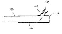
図1は、本発明の1つの実施形態に係る閉塞を横切るアクセスを提供するシステム100の各種構成部品を示す。ある実施形態において、システム100は、スリーブ110及びバルーン120を含んでよい。
FIG. 1 illustrates various components of a
ある実施形態において、スリーブ110は、近位部分112、反対の遠位部分114及びそれらの間の通路116を含むことができる。通路116は、図示されるように、遠位部分114とスリーブ110の残部との間の接合点117を横切って延在してよい。また、説明されるように、通路116を通って閉塞を横切るアクセスを提供するために、スリーブ110の遠位部分114は、閉塞部位を横切って延在するように設計されてよい。
In one embodiment, the
図1に示されるように、スリーブ110は、実質的にチューブ状の形状であってよい。しかし、チューブ状の形状として記載されているが、閉塞部位を横切るアクセスを提供すために、スリーブ110の形状がスリーブ110の案内(又は、ナビゲーション、navigation)に役立ち得るように、スリーブ110は、個々の用途に応じて、任意の他の望ましい形状を有してよい、ということは留意されるべきである。
As shown in FIG. 1, the
いくつかの実施形態において、スリーブ110は、脈管中の入り組んだ経路を通って案内する(又は、ナビゲーションする、navigate)ことができるように十分に柔軟であってよい。追加的に又は代替的に、スリーブ110は、脈管を通ってスリーブ110を前進させるために付加されている近位の力の存在下で、曲がらず又は折り返されないように十分に固くてよい。
In some embodiments, the
スリーブ110が脈管を通って閉塞部位に前進することができる限りは、スリーブ110は、用途に応じて、任意の望ましい長さを有してもよい。例えば、1つの実施形態において、スリーブが長い又は入り組んだ脈管を通って閉塞部位に前進することができるように、スリーブ110は比較的長くてよく、例えばロングカテーテルであってよい。他の実施形態において、スリーブ110は、閉塞を横切って送達されることができる比較的短いスリーブであってよい。スリーブ110は、用途及び脈管の大きさに応じて、スリーブ110が脈管内にフィットすることを可能にするのに十分な任意の直径も有してよい。ある実施形態において、スリーブ110の直径は、全体に渡って実質的に一定のままでよい。望ましい場合には、必要に応じて、スリーブ110の直径は、スリーブ110の長さに沿って変化してよい。
The
1つの実施形態において、スリーブ110は、脈管の中への挿入によるスリーブ110と脈管壁との間の摩擦を低減するために、外側表面上のコーティングをさらに含んでよい。1つの実施形態において、コーティングは、スリーブ100の外側表面全体を覆ってよい。代替の実施形態において、コーティングは、遠位部分114のみに配置されてよい。勿論、コーティングは、他の形態でも同様に外側表面上に配置されてよい。同様に、スリーブ110は、外返りの間の摩擦を低減するために、内側表面上のコーティングを含んでよい。1つの実施形態において、内側コーティングは、スリーブ110内側表面全体を覆ってよい。代替の実施形態において、コーティングは、スリーブ110の遠位部分114のみに配置されてよい。勿論、コーティングは、他の形態でも同様に内側表面上に配置されてよい。
In one embodiment, the
ある実施形態において、スリーブ110の遠位部分114は、閉塞部位を横切ってスリーブ110から延在するように設計されてよい。いくつかの実施形態において、スリーブ110から延在するために、遠位部分114は、内返り状態から外返り状態に移動することができてよい。図2に見られるように、内返り状態において、遠位部分114は、スリーブ110の中に折り返されてよい。この位置において、スリーブ110の長さは比較的短くされてよい。しかし、矢印202により示されるように、外返しの間、図2aの内返しされた/折り返された位置から、図2bに示される外返しされた/延在させられた位置に移動することにより、遠位部分114は、スリーブ110の残部から延在してよい。
In certain embodiments, the
記載の形態で外返しすることができる遠位部分114を提供することにより、遠位部分114は閉塞部位を横切って延在することができて、閉塞部位より遠位の部位へのアクセスを可能にする。とりわけ、一旦遠位部分114が閉塞部位を横切って延在させられると、カテーテル、バルーンカテーテル及びプラーク除去システム等のような物体及びデバイスは、通路116を通り、閉塞部位を通過して前進させられることができる。スリーブ110の遠位部分114は、閉塞部位において脈管に対する保護を提供してもよく、スリーブ110を通過するデバイスは、閉塞部位及びその周囲の脈管を損傷しにくい。
By providing a
様々な大きさ又は長さを有し得る閉塞部位を横切って延在するために、1つの実施形態において、遠位部分114は、用途に応じて任意の望ましい長さを有してよい。1つの実施形態において、比較的長い閉塞部位を横切って延在するよう外返しすることができるように、遠位部分114は比較的長くてよい。他の実施形態において、遠位部分114は、より長い長さが閉塞部位を横切るアクセスを提供するのに必要とされない場合は、比較的短くてよい。勿論、閉塞の長さに適応するために、スリーブ110内に比較的長い遠位部分114を提供し、その後、外返り部位を横切る、スリーブ110からの長さ又は外返り量を制御することも、本発明の範囲内である。
In one embodiment, the
遠位部分114は、折り返す、曲げる又は内返り状態から外返り状態に延在する必要が有り得るため、ある実施形態において、遠位部分114は、そのような折り返し、曲げ及び延在を可能にするのに十分に柔軟且つしなやかである材料から作られてよい。
In some embodiments, the
いくつかの実施形態において、遠位部分114は、スリーブ110の残部と一体であってよい。そのようなものとして、遠位部分114は、スリーブ110の残部と共に単一の部品として成形又は構成されてよい。他の実施形態において、遠位部分114は、スリーブ110の残部に取り付けられることができる別個の部品であってよい。そのような実施形態において、遠位部分114がスリーブ110の残部内から外返しされることができる限り、遠位部分114は、任意の適切な方法でスリーブ110の残部に取り付けられてよい。
In some embodiments,
いくつかの実施形態において、遠位部分114及びスリーブ110の残部は、同じ材料から作られてよい。他の実施形態において、遠位部分114及びスリーブ110の残部は、異なる材料から作られてよい。例えば、1つの実施形態において、望ましい場合には、スリーブ110の遠位部分114のみが、外返りを可能にする実質的に柔軟な材料から作られてよく、一方、スリーブ110の残部は柔軟性に劣る材料から作られてよく、脈管を通しての送達の間、スリーブ110の変形を最小限に抑える。
In some embodiments, the
スリーブ110及び遠位部分114は、人体又は動物体の脈管の中に挿入されるように設計され、ある実施形態において、スリーブ110及び/又は遠位部分114は、生体適合性のある材料から作られることができる。材料の生体適合性は、脈管内でのスリーブ110の使用に起因する副作用の発生を最小限に抑えるのに役立ち得る。適当な材料の例は、様々な種類の金属、プラスチック又は任意の他の材料を含む。いくつかの例において、スリーブ110は生体吸収性材料から作られてもよく、スリーブ110は、時間と共に体に吸収されるように体内に留まってよい。
The
図1に戻って参照されるように、スリーブ110の遠位部分114を送達し、閉塞部位を横切る通路116を提供するために、本発明のシステム100は、スリーブ110の遠位部分114を内返り位置から外返り位置に移動するように、遠位部分114に力を及ぼすことが可能なバルーン120を含んでもよい。いくつかの実施形態において、後述のように、バルーン120はスリーブ110内に位置付けられてよく、バルーン120が膨張させられると、バルーン120は遠位部分114を押すことができ、スリーブ110内から遠位部分114を外返しすることができる。
Referring back to FIG. 1, to deliver the
図1に示されるように、ある実施形態において、バルーン120は、バルーン120を膨張及び収縮するためのルーメン126を含んでよい。認識されることができるように、ルーメン126は、例えば、バルーン120を膨張及び収縮するために流体が流れることができるチューブであってよい。いくつかの実施形態において、ルーメン126は、バルーン120に永久的に又は取り外しできるように連結されてよい。いくつかの実施形態において、ルーメン126は、バルーン120と一体であってよい。そのため、バルーン120及びルーメン126は単一のユニットとして作られてよい。いくつかの実施形態において、図1に示されるように、バルーン120とルーメン126との単一のユニットは、近位部分(すなわちルーメン126)より広い遠位部分(すなわちバルーン120)を有してよい。あるいは、単一のユニットは、類似の直径を有するバルーン120及びルーメン126と、直径が実質的に均一であってよい。後に詳述されるように、いくつかの実施形態において、バルーン120自身が様々な直径を有してよい、ということも留意されるべきである。いくつかの実施形態において、膨張チューブは、膨張チューブが収縮させられると同時にスリーブ110内の最小の空間の中に潰れることを可能にする薄壁材料から作られてよい。そのような材料の1つはPETであるが、任意の薄壁材料が許容できる。
As shown in FIG. 1, in one embodiment, the
図3a〜3に見られるように、スリーブ110の遠位部分114を外返しするために、ある実施形態において、バルーン120は、バルーン120が膨張させられると、内返り位置から外返り位置に移動するように設計されてよい。図3aに示されるように、内返り位置において、バルーン120は内返しされてよく、バルーン120自身の中に折り返されてよい。バルーン120は、バルーン120の遠位端を外返しすることができる流体(例えば、液体又は気体)で満たされてよく、バルーン120が膨張させられる際、図3bに示されるようにバルーン120が完全に延在させられた位置に達するまで、矢印302で示されるようにバルーン120が延在する。バルーン120が延在するとき、バルーン120は、スリーブ110の内返しされた遠位部分114と係合してよく、内返り位置から外返り位置にスリーブ110の遠位部分114を押すように働いてよい。バルーン120は、内返り位置というよりはむしろ、折り返され、収縮され又はさもなければ他の方法で圧縮されてもよく、一旦膨張させられたら、バルーン120は、内返り状態から外返り状態にスリーブ110の遠位部分114を押すことができる、ということを当業者は認識するだろう。
As seen in FIGS. 3 a-3, in an embodiment to balloon the
図3cに関連して、いくつかの実施形態において、システム100は、スリーブ110の近位端にコネクタ130を含んでよく、ルーメン126を膨張機構(示されない)に接続することを容易にし、ルーメン126を通ってバルーン120の中に及び外に流体を導くことができる。膨張機構は、ポンプ(例えば、手動又は自動のポンプ)、シリンジ、又は使用中にバルーン120を膨張及び/若しくは収縮することができる他のデバイスであってよい。いくつかの実施形態において、コネクタ130は、1つ以上のポート131、132を有してよい。いくつかの実施形態において、ポート132は、バルーン120を膨張させる膨張ポートとして利用されてよい。ルーメン126は、スリーブ110の内側でポート132に接続さてよく、膨張機構は外側でポート132に接続されてよくて、バルーン120を膨張機構に流体接続する。図3dに示されるように、バルーン130は、膨張ポート132を介してバルーン120を加圧することにより、外返しされてよい。勿論、膨張ボートについては、バルーンを展開するのに十分な力で流体が入ることができる限り、他の配置が可能である。
Referring to FIG. 3c, in some embodiments, the
図3eに示されるように、コネクタ130は、ポート133を介して外科用器具又は外科用材料をスリーブ110の中に導入することも可能にする。いくつかの実施形態において、外返りの後に続くバルーンの収縮は、バルーン120を潰してよく、外科用器具125がスリーブ110を通して前進させられることを可能にする。いくつかの実施形態において、ポート131、132は封止可能であり、スリーブ110の内側ルーメンと周囲の空間との間の流体シールを提供する。
As shown in FIG. 3 e, the
図4aに関連して、バルーン120は、スリーブ110内に内返り状態で位置付けられてよい。ある実施形態において、スリーブ110の遠位部分114は、内返り状態のバルーン120と共に、バルーン120により形成されたポケット402の中に折り返されてよい。遠位部分114をポケット402の中に折り返すことは、遠位部分114が、送達のためにポケット402の中に適切に固定されることを確実にするのに役立ち得る。
Referring to FIG. 4a, the
バルーン120はまた、膨張させられるとき、外返りの間のスリーブ110の不必要な移動を最小限に抑え得る、ということも留意されるべきである。例えば、遠位部分114が外返しされると、遠位部分114は閉塞を押し得て、また後方への力を生み出し得て、脈管を通って後方にスリーブ110(及び/又はバルーン120)を押す傾向があり得る。しかし、バルーン120が膨張させられると、バルーン120はスリーブ110の内壁を圧迫し得て、またスリーブを脈管の内壁に押さえつけ得て、従って、スリーブと脈管との間に静摩擦を生み出す。摩擦は、スリーブ110を適当な位置に固定するよう働くことができ、スリーブ110は、いかなる後方の圧力に対しても、移動することなく耐えることができる。
It should also be noted that the
図4bに示されるように、膨張させられると、バルーン120は、実質的に直線の形態で延在し得て、閉塞部位を通過してスリーブ110を延在するのに役立つ。言い換えると、バルーン120は、実質的に細長い形状を有してよく、膨張させられると、バルーン120は実質的に遠位の方向に延在して、閉塞部位を通過してスリーブ110の遠位部分114を延在するのに役立つ。
As shown in FIG. 4 b, when inflated, the
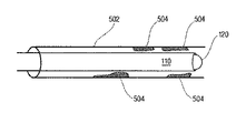
1つの実施形態において、バルーン120及びスリーブ110の遠位部分114は、柔軟且つしなやかであるように設計されるため、バルーン120及び遠位部分114は、閉塞部分を通る最も抵抗が小さい経路を探すよう働き得る。次に図5aを見ると、例えば、脈管502が閉塞部位504(又は、一連の閉塞504)により塞がれている場合、膨張の間、バルーン120の中に導入された流体は、バルーン120、及び最も抵抗が小さい経路に続く閉塞部位を通るスリーブ110の遠位部分114を押す傾向があるだろうから、矢印506により示されるように、バルーン120は、外返しされているとき、閉塞部位504を通る最も容易な経路を探し得る。このことはシステム100の使用者が、さもなければガイドワイヤ又は他のデバイスを用いて閉塞部位を調べることにより見つけることが困難又は不可能であろう閉塞部位504を通る経路又は開口部を、容易に、見ずに又は自動的に見つけることを可能にし得る。
In one embodiment, since the
1つの実施形態において、バルーン120が閉塞部位を通って外返しされたとき、バルーン120が閉塞部位におけるいかなる閉塞をも拡大又は拡張するように設計されてよい。図5bに示されるように、バルーン120は膨張し続けて閉塞部位504を押し通すため、バルーン120は、脈管502を通る通路を掃除して、閉塞部位504を通る経路を拡大してよい。勿論、バルーン120は閉塞部位504を拡大するため、バルーン120はスリーブ110を外返しするようにも働き得て、スリーブ110は、脈管を通り且つ閉塞部位504を横切る通路を作り出す。
In one embodiment, when the
図4cに戻って参照されるように、外返りに続いて、バルーン120は、スリーブ110の通路116に沿ったアクセスを可能にするように収縮してよく、デバイスがスリーブ110を通して導かれてよい。例えば、図4cに示されるように、バルーン120は、収縮させられたとき、より小さな輪郭を有してよく、カテーテル404(又は他のデバイス)が、スリーブを通り且つ閉塞部位を横切って前進させられてよい。1つの実施形態において、収縮させられたバルーン120は、カテーテル404が通過することを可能にするために、スリーブ110の内壁に隣接して位置付けられてよい。他の実施形態において、カテーテル404が閉塞部位及び/又は閉塞より遠位の部位にアクセスすることができる限り、バルーン120は、収縮させられたとき、他の配置で位置付けられてよく、又はカテーテルがスリーブ110の中に又はそこを通って前進させられる前に、スリーブ110から後退若しくは取り除かれてよい。
Referring back to FIG. 4 c, following eversion, the
いくつかの実施形態において、収縮機構(示されない)は、ルーメン126を通ってバルーン120の外に流体を導くことにより、バルーン120を収縮させてよい。上述のように、収縮機構は、ポンプ、シリンジ又はバルーン120の中及び外に流体を移動できる他のデバイスであってよい。他の実施形態において、バルーン120は、カテーテル404がスリーブ110を通して前進させられるときにバルーン120を脇に押すことにより、カテーテル404(又は他のデバイス)がバルーン120を収縮させるように設計されてよい。そのような設計において、バルーン120はテーパー状の壁(例えば壁406)を有してよく、カテーテル404が壁406に押すと、バルーン120は、カテーテル404とスリーブ110の内壁との間に押し込まれた状態又は圧縮された状態になる。押し込む動作は、ルーメン126を通してバルーン120の外に流体を押し出すことにより、バルーン120を収縮し得る。バルーン120を収縮させる他の方法が用いられてもよい。例えば、バルーン120がもはや必要でない及び/又はディスポーザブルである場合は、デバイスがスリーブの中に前進させられてよくて、バルーン120に穴を開けて、バルーン120が収縮する。
In some embodiments, a deflation mechanism (not shown) may deflate
脈管内の閉塞を通過してスリーブ110を延在させるために、バルーン120は、閉塞を迂回する(又は、回避する、bypassing)ことが可能な、柔軟且つ十分に強い材料から作られることができる。バルーン120はさらに、バルーン120を外返しする十分な力に耐えることが可能な、十分に強い材料から作られるべきである。他の実施形態において、バルーン120の材料は、バルーン120が十分な圧力に耐えることを可能にするために、流体に対して不浸透性であってよい。バルーン120は人体又は動物体の脈管内に挿入されるように設計されるため、バルーン120は生体適合性のある材料から作られるべきである。材料の生体適合性は、脈管内でのバルーン120の使用に起因する副作用の発生を最小限に抑えるのに役立ち得る。
In order to extend the
バルーン120はさらに、外返りプロセスに役立つことができる任意の材料から作られることができる。1つの実施形態において、いとも容易く外返しし且つ閉塞を迂回するために、バルーン120は、抵抗及び摩擦を最小限に抑える材料から作られることができる。例えば、バルーン120は、実質的に滑らかであり及び/又は比較的低い摩擦係数を有する材料から作られることができる。望まれるべき場合には、バルーン120は、外返し、膨張及び収縮に役立つことができるコーティング、又はバルーン120にとって望ましいことがあり得る任意の他の特性をさらに含んでよい。コーティングは、バルーン120の内側表面、外側表面又はそれらの組み合わせに適用されてよい。
The
ある実施形態において、バルーン120の長さは、様々な特性に応じて変化してよい。場合によっては、バルーン120の長さは、脈管の長さに依存してよい。他の例において、バルーン120の長さは、遠位部分114の長さに応じて変化してよい。さらなる他の例において、バルーン120の長さは、見込まれる閉塞部位の長さに応じて変化してよい。バルーン120の長さは、バルーン120がスリーブ110内にフィットし及び/又はスリーブ110を外返しすることを可能にすべきである、ということは留意されるべきである。
In certain embodiments, the length of
同様に、バルーン120がスリーブ110内及び脈管内にフィットすることを可能にする直径である限り、バルーン120は、任意の望ましい直径を有してもよい。いくつかの例において、バルーン120は、膨張させられたとき、バルーン120がスリーブの内壁に対する流体密封のシールを作り出すように、十分に大きな直径を有してもよい。バルーン120は、バルーン120がスリーブ120を脈管の内壁に押し当てることができるように、十分に大きな直径を有してもよい。1つの実施形態において、バルーン120は、膨張状態であるときに、バルーン120が実質的に脈管壁に一致することを可能にする直径を有してもよい。しかし、膨張状態において、スリーブ110を破る可能性を最小限に抑えるために、バルーン120の直径はスリーブ110の直径より小さくてもよい。勿論、より大きい又はより小さい直径も可能である。
Similarly,
バルーン120は、バルーン120がスリーブ110内及び脈管内にフィットすること及び遠位端114を外返しすることを可能にする形状である限り、任意の望ましい形状を有してもよい。1つの実施形態において、バルーン120は実質的にチューブ状の形状を有してよく、バルーン120が実質的に脈管に一致することを可能にする。勿論、他の幾何学的形状も本発明の範囲内である。
The
再び図4a〜cに関連して、外返りの間のバルーン120の前進又は後退を最小限に抑えるために、システム100は、スリーブ110の一部分をバルーン120の一部分に連結するよう働き得る連結機構408を含んでよい。連結機構は、スリーブ110内からのバルーンの前進又は後退を最小限に抑えつつ、バルーン120の外返りを可能にするように設計されてよい。勿論、いくつかの実施形態において、連結機構は、望ましい場合には、外返りの間のバルーン120の少なくともいくらかの軸方向の移動を可能にしてよい。連結機構は、バルーン120及びスリーブ110を確実に連結することが可能な任意の機構であってよい。例えば、連結機構は、接着剤、テープ、ベルクロ(velco)、クリップ又は任意の他の市販の機構であってよい。他の実施形態において、連結機構は、バルーン120とスリーブ110との間の摩擦を増加させる機構であってよい。例えば、連結機構は、バルーン120及び/又はスリーブ110の粗い又は穴の開いた部分であってよく、その部分は、バルーン120が膨張させられてスリーブ110に押し当てられると、摩擦を生み出す。
Referring again to FIGS. 4 a-c, to minimize advancement or retraction of the
一旦スリーブ110が外返しされたら、スリーブ110は、カテーテル404のような物体が閉塞部位を横切って送達されることを可能にする通路117を提供してよい。1つの実施形態において、通路116は、遠位端114とスリーブ110の残部との間の接合点117を横切って延在してよく、カテーテル404は、閉塞部位又は閉塞部位より遠位の部位にアクセスすることができる。閉塞部位を横切るアクセスを提供するために、カテーテル404又は他のデバイスは、スリーブ110の通路116に沿って、スリーブ110の遠位部分114に向かって前進させられてよい。ある実施形態において、カテーテル404は、スリーブ110の潰れ、折り返し又は圧縮を最小限に抑えるように、スリーブ110の長さに沿って十分な構造保全(structural integrity)をスリーブ110に提供するように設計されてよい。1つの実施形態において、図4cに示されるように、カテーテル404が脈管を通って前進させられるとき、カテーテル404はスリーブ110により保護されてよい。ある実施形態において、カテーテル404は、カテーテル404がスリーブ110の通路116に沿って前進させられることができる限り、任意の市販のカテーテルであってよい。例えば、カテーテル404は、送達、例えば血管内ステント又は血管形成のためのバルーンカテーテルのための治療用カテーテルであってよい。
Once the
本発明は、内視鏡(示されない)を用いる1つの実施形態に従って、展開されることができる。内視鏡は、脈管を通してシステム100を関心部位に案内するのに役立ち得る。ある実施形態において、内視鏡は、スリーブ110の周囲に位置付けられるように設計された本体位置調整(又は、本体位置調整デバイス、ボディポジショニング、body positioning)が備えられてよい。
The present invention can be deployed in accordance with one embodiment using an endoscope (not shown). An endoscope may help guide the
図6a〜cに見られるように、他の実施形態において、本発明のシステム100は、ガイドワイヤ(例えば、ガイドワイヤ602)が脈管を通してスリーブ110を案内及び導くのに役立つことを可能にするように設計されてよい。いくつかの実施形態において、ガイドワイヤは、脈管を通してシステム110を関心部位に向かって押すように設計されてよい。そのような設計において、システム100は、ガイドワイヤ602の端部を収容することができるシステム100の表面上に、ポケット又はスロット118(図1参照)を含んでよい。ガイドワイヤ602は、スロット118内に位置付けられてよく、ガイドワイヤ602が脈管604を通って前進するとき、ガイドワイヤ602は、脈管604を通ってスリーブ110を閉塞部位606に向かって押す。他の実施形態において、スロット118は、スリーブ110がガイドワイヤ602の長さに沿ってスライドすることを可能にしてよい。そのような実施形態において、ガイドワイヤ602が初めに、脈管604の中へ閉塞部位606(図6に示される)に向かって前進させられてよく、その後、スリーブ110が閉塞部位606に隣接して位置付けられるまで、スリーブ110が、ガイドワイヤ602の長さに沿って前進させられてよい。
As seen in FIGS. 6a-c, in another embodiment, the
ある実施形態において、ガイドワイヤ602はさらに、スリーブ110を閉塞部位606に隣接して位置付けることが可能であってよく、バルーン120は閉塞部位606を横切ってスリーブ110を外返しすることができる。ガイドワイヤ602は、スリーブ110の案内を可能にする任意の形態で位置付けられることができるが、その設計は、外返りの間、バルーン120及びスリーブ110のいかなる閉塞をも最小限に抑えるべきである、ということは留意されるべきである。言い換えると、ガイドワイヤ602は、ガイドワイヤ602が遠位端114の外返りを妨げないように位置付けられるべきである。いくつかの実施形態において、米国仮特許出願第61/435,517号(2011年1月24日出願、参照により全体として本明細書に組み入れられる)に記載されているようなガイドワイヤは、スリーブ110を閉塞部位606に案内するのに用いられることができる。他の実施形態において、ガイドワイヤ602は、市販の任意のガイドワイヤであってよい。
In certain embodiments, the
他の実施形態において、スリーブ110は、閉塞部位606を横切るガイドワイヤ602の送達を容易にするように、ガイドワイヤ602と併せて用いられてよい。そのような実施形態において、スリーブ110の遠位端114が外返しされてよく、閉塞部位606を横切る通路116を提供する。次いで、ガイドワイヤ602は、通路116を通り且つ閉塞部位606を横切って前進されてよい。その後、スリーブ110は取り除かれてよく、閉塞部位606を横切ってガイドワイヤ602を適当な位置に残す場合には、ガイドワイヤ602は、閉塞部位に向かって又はそこを通って他のデバイスが前進するための軌道として用いられてよい。
In other embodiments, the
操作において、体の中に挿入するシステム100を準備するために、バルーン120は、スリーブ110内に位置付けられてよい。その後、スリーブ110の遠位部分114及びバルーン120の遠位端両方が内返しされることができ、スリーブ110の遠位部分114がスリーブの残部の中に折り返される。いくつかの例において、バルーン120は、遠位部分114が中に位置し得るポケット402を作るように内返しされてよい。カテーテル404は、スリーブ110の中に配置されてもよい。
In operation, the
一旦装着され(又は、ロードされ、loaded)たら、図6aに示されるように、システム100は、体内の脈管の中に挿入されてよく、脈管604に沿って閉塞部位606に向かって前進させられてよい。一旦閉塞部位606に到達したら、バルーン120は、遠位部分114を外返しするように膨張させられてよく、閉塞部位606を横切ってバルーン120を送達してよい。バルーン120の膨張は、加圧された流体を、ルーメン126及び/又は膨張ポートを介してバルーン120の中に導入することを必要としてよい。図6bに示されるように、バルーン120が膨張させられると、バルーン120は、閉塞部位606を横切ってスリーブ110内からスリーブの遠位部分114を押して外返ししてよい。いくつかの例において、上述のように、バルーン120が膨張させられたとき、バルーン120は、見ずに又は自動的に、閉塞部位606を通る経路を探してもよい。膨張は、バルーン120に閉塞部位を拡大させることにより、閉塞部位606を通る経路を開通し又は広げることもできる。図6cに示されるように、外返りに続いて、バルーン120は収縮させられ及び/又は取り除かれ、カテーテル404は、通路116を通って前進させられてよく、閉塞部位又は閉塞部位より遠位の部位にアクセスする。
Once installed (or loaded and loaded), as shown in FIG. 6a,
図7a〜7bに関連して、いくつかの実施形態において、バルーン120は、閉塞部位を通る通路を形成するのに用いられてよい。そのため、一旦バルーン120がスリーブ110から外返りされて、閉塞部位を横切って位置付けられたら、バルーン120は、バルーン120の遠位端を開くために穴を開けられてよく、その後、閉塞部位を横切るライニングを提供する。この設計を使用する場合、図7a〜7bに示されるように、狭窄を通る通路を提供するために、バルーン120が遠位部分114の代わりに用いられてよい、ということは留意されるべきである。あるいは、いくつかの実施形態において、遠位部分114に加えて、図7a〜7bに示されるバルーン120を用いることは有益で有り得る。
In some embodiments, referring to FIGS. 7a-7b, a
いくつかの実施形態において、膨張させられたバルーン120の遠位端に穴を開けるために、十分な長さ及び強度を有するパンクワイヤ(又は、パンクチャワイヤ、puncture wire)が備えられてよい。ワイヤは、スリーブ110の断面直径よりも小さい断面直径を有してよい。例えば、パンクワイヤ150は、約0.015インチと約0.025インチとの間の直径を有してよい。パンクワイヤ150は、ワイヤがバルーン120の遠位端124を通して穴を開けることを可能にするのに十分な剛性を有する材料から作られてよい。いくつかの実施形態において、ワイヤは、ステンレス鋼又はニチノールのような超弾性金属から作られてよいが;望ましい剛性及び柔軟性を有する任意の材料が許容できる。
In some embodiments, a puncture wire of sufficient length and strength may be provided to puncture the distal end of the
パンクワイヤ150は、コネクタ130の開口部を通ってシステム100に入ってよい。いくつかの実施形態において、パンクワイヤ150は、スリーブの長さの少なくとも2倍の長さを有してよい。この長さは、脈管中のパンクワイヤの位置が維持されつつ、パンクワイヤ150がバルーン120に穴を開けた後に、スリーブ110が脈管から取り除かれることを可能にする。この形態において、パンクワイヤ150は、脈管を通ってパンクワイヤ150を越えて進むことができる脈管ステント留置カテーテルのような第2のデバイス(示されない)のための案内として働き得る。
The
システム100の位置を関心部位に固定するために、いくつかの実施形態において、本開示のシステム100は、バルーン120及び遠位部分114の膨張及び外返りの間、システムを適当な位置に固定するアンカーカフ(又は、アンカーリングカフ、anchoring cuff)を含んでよい。
To secure the position of
図8を参照すると、いくつかの実施形態において、本開示のシステム100は、スリーブ110外側表面上に配置されたアンカーカフ800を含んでよく、システムを周囲の脈管壁に固定する。単一のアンカーカフ800を用いて示されているが、望ましい場合には、脈管内側のシステム100の増加したアンカーのために、複数のアンカーカフ800が用いられてよい、ということは勿論理解されるべきである。いくつかの実施形態において、アンカーカフ800は、スリーブ110の遠位先端より近位に位置付けられてよい。図8に示されるように、アンカーカフ800は、バルーン120から独立していてよい。アンカーカフ800は、スリーブ110のルーメン801と流体連通していてよく、スリーブ110を通してアンカーカフ800が膨張又は収縮することを可能にする。いくつかの実施形態において、コネクタがスリーブ100の近位端に配置されることができて、アンカーカフ800を膨張又は収縮するために、膨張機構をルーメン801に連結することを容易にする。
Referring to FIG. 8, in some embodiments, the
いくつかの実施形態において、バルーン120は、バルーン120をスリーブ110に連結するために、アンカー部(又は、アンカーリング部、anchoring section)802を含んでよい。いくつかの実施形態において、アンカー部802は、スリーブ110の外側でスリーブ110に固定されてよい。いくつかの実施形態において、アンカー部802は、スリーブの110内側でスリーブ110に固定されてよい。いくつかの実施形態において、図8に示されるように、アンカー部802は、スリーブ110に直接連結されてよい。いくつかの実施形態において、上述のように、バルーン120は、コネクタ130を用いるスリーブ110に連結されてよい。バルーン120は、脈管中の狭窄を通して配置される外返り部804を含んでもよい。
In some embodiments, the
いくつかの実施形態において、単一の膨張ルーメン801は、バルーン120の外返り部804を内返り位置から外返り位置に移動するためと、アンカーカフ800を膨張させて脈管内側のスリーブ110に固定するためとの両方に用いられてよい。そのような実施形態において、アンカーカフ800は、スリーブ110の壁の1つ以上の穴808を通って膨張ルーメン801と流体連通していてよい。この形態において、最初に、アンカーカフ800がスリーブ100(110)の初期の加圧により膨張させられてよく、スリーブ110を脈管壁に固定する。とりわけ、アンカーカフ800の中に導入された圧力は、最初は膨張圧と等しくてよい。その後、アンカーカフ800中の圧力は、バルーン120の外返り部804がスリーブ110から脈管中の狭窄を横切って外返り位置に外返しし得る点に外返り圧力が到達するまで、増加することが可能であってよい。アンカーカフ800中の圧力は、システム100が狭窄部位から後戻りしないことを確実にしつつ、狭窄を通して外返り部を外返しすることを確実にするのに必要であるように、増加することが可能であってよい。アンカーカフ800内の圧力がシステム100の十分な固定を提供する水準であり、追加の圧力が外返り部804の外返りに向けられるまでは、外返り部804の外返りは必ずしも起こらなくてよい、ということは認識されるべきである。
In some embodiments, a
そのような設計は、単一の噴射装置を用いた加圧により、アンカーカフ800中の圧力の自己調節(self-adjustment)を提供し得ており、アンカーカフ800中の圧力は外返り圧力と等しい。狭窄を通してのバルーンの外返りの前に、カテーテルの中への流体の噴射がデバイスを固定する。狭い狭窄を通してバルーン120(及び存在する場合、遠位部分114)を外返しするのに高圧が必要とされる場合、同等の高圧がアンカーカフ800中に保持され、スリーブ110の増加したアンカーを狭窄部位の近傍の位置に提供し、狭窄を通ってバルーン120及び遠位部分114の外返りの間、スリーブ110が後退することを防止する。勿論、別々のルーメンがアンカーカフ800及びバルーン120に提供されてよい。
Such a design can provide self-adjustment of the pressure in
いくつかの実施形態において、図9a〜9cに示すように、スリーブ110を脈管内側に固定するために、バルーン120は、脈管内側のスリーブ110を固定するためのアンカー部(又は、アンカーリング部、anchoring section)、及び脈管中の狭窄を通して配置される外返り部904を含んでよい。いくつかの実施形態において、バルーン120は、バルーン120の外返り部904より大きい直径を有するアンカー部902と共に、様々な直径を有してよい。
In some embodiments, as shown in FIGS. 9a-9c, to secure the
図9a〜9cに関連して、いくつかの実施形態において、上述のように、バルーン120の近位端は、スリーブ110の近位端においてコネクタ130に接続されてよい。バルーン120の膨張の前に、図9aに示されるように、バルーン120のアンカー部902は、遠位部分114とスリーブ110の残部との間の接合点117を越えて遠位に延在してよい。図9bに示されるように、バルーン120が最初に膨張させられる際、アンカー部902が最初に膨張し得る。アンカー部902の膨張した直径は、脈管の内径に等しい又はそれよりわずかに大きくてよく、外返り部904を狭窄又は閉塞を通して外返しするとき、アンカー部902が脈管の壁に接触してスリーブ110を適切な位置に保持することを可能にする。次に、図9cに示されるように、バルーン120の膨張が継続すると、バルーン120の外返り部904がスリーブ110から外返しされて、狭窄を通って遠位部分114を配置する。いくつかの実施形態において、外返り部904は、アンカー部902よりも小さな直径を有してよく、外返り部分904が脈管の狭窄部位を通ってフィットすることを確実にする。図9a〜9cには示されないが、いくつかの実施形態において、上述のように、バルーン120の外返り部904は遠位末端に穴を開けられてよく、外返り部904を開き、狭窄を通して追加のライニングを提供する。
In some embodiments, with reference to FIGS. 9a-9c, the proximal end of the
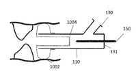
図10a〜10cに関連して、いくつかの実施形態において、バルーン120の近位端は、スリーブ110の遠位端に接続されてよく、スリーブ110の遠位部分114無しに用いられてよい。そのような実施形態において、図10aに示されるように、バルーン120の外返り部1004はスリーブ110の中に内返しされてよい。図10bに示されるように、バルーン120が最初に膨張させられると、アンカー部1002が最初に膨張し得る。アンカー部1002の膨張した直径は、脈管の内径に等しい又はそれよりわずかに大きくてよく、外返り部1004を狭窄又は閉塞を通して外返しするとき、アンカー部1002が脈管の壁に接触して、スリーブ110を適切な位置に保持することを可能にする。次に、図10cに示されるように、バルーン120の膨張が継続すると、バルーン120の外返り部1004がスリーブ110から外返しして、最終的に狭窄を通して位置付けられる。いくつかの実施形態において、外返り部1004は、アンカー部1002よりも小さな直径を有してよく、外返り部分904(1004)が脈管の狭窄部位を通ってフィットすることを確実にする。最終的に、上述のように、バルーン120の外返り部1004は遠位末端に穴を開けられてよく、外返り部1004を開き、狭窄に外科用器具を通過させるために、狭窄を通してライニングを提供する。
10a-10c, in some embodiments, the proximal end of the
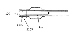
図11に関連して、いくつかの実施形態において、例示の(instant)システム100は、ガイドワイヤシース1105も含んでよい。ガイドワイヤシース1105は、スリーブ110の周囲に配置されてよい。いくつかの実施形態において、ガイドワイヤシース1105は、ガイドワイヤシース1105がスリーブ110の周囲に位置付けられると際、ルーメン1110がガイドワイヤのルーメン1110を通っての通過に適応し得るように形成され得るような、形状及び大きさであってよい。ルーメン1110は、スリーブ110が、脈管中に位置付けられたガイドワイヤに沿って前進させられることを可能にする。いくつかの実施形態において、ガイドワイヤシース1105は、複数のルーメン、スリーブ110をガイドワイヤシース1105の中に挿入して、ガイドワイヤシース1105をスリーブ110の周囲に位置付けるための1つのルーメン、及び1つ以上の追加のルーメンを通してガイドワイヤ又は他の器具を前進させるための前記1つ以上の追加のルーメンを含んでよい。
In some embodiments, in conjunction with FIG. 11, an
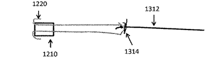
図12a〜12bに関連して、バルーン内返りサブアセンブリ1200が、バルーン12をスリーブ110に挿入及び連結することを容易にするために備えられてよい。いくつかの実施形態において、バルーン内返りサブアセンブリ1200は、ブッシング1210に連結されたバルーン120を含んでよい。いくつかの実施形態において、バルーンは、アンカー部1220において、ブッシング1210の外側に連結されてよい。バルーン内返りサブアセンブリ1200がスリーブ110の遠位端の中に挿入されてよく、バルーン120をスリーブ110に連結する。いくつかの実施形態において、スリーブ110は、広がった遠位部1212を有してよく、バルーン内返りサブアセンブリ1200を受容する。バルーン内返りサブアセンブリ1200がスリーブ110の中に挿入されると、ブッシング1210は、バルーン材料をスリーブ110の壁に押し当て得て、それによりバルーン120をスリーブ110に連結する。
With reference to FIGS. 12 a-12 b, a
いくつかの実施形態において、図12c〜12dに示されるように、バルーン内返りサブアセンブリ1200は、スリーブ110の外へのバルーン120の内返りを容易にする。例えば、バルーン120は、スリーブ110の中へのバルーン内返りサブアセンブリ1200の挿入の前に、部分的にブッシング1210の中に内返しされてよい。いくつかの実施形態において、バルーン120の閉じた端部がチューブ状のマンドレル1216の中に挿入されてよく、図12cに示されるように、その後、バルーン120の閉じた端部は、ブッシング1210の中に前進させられることができ、バルーン120を少なくとも部分的に内返しする。バルーン内返りサブアセンブリ1200は、バルーン120の内返り前又は後に、スリーブ110の中に挿入されてよい。少なくとも部分的に内返ししているバルーン120は、処置の間にバルーン120をスリーブ110の外に展開するのに必要とされる外返り圧力を減少させる。
In some embodiments, as shown in FIGS. 12 c-12 d, the
図13a〜13dは、バルーン挿入サブアセンブリ1200を形成する方法の実施形態を示す。初めに、ブッシング120が、端部が開いたバルーン材料1310内側に配置されることができる。縫合糸1312は、バルーン材料1310及びブッシング1210を通過させられることができ、バルーン材料1310の一方の端部1314において結び目を作るのに用いられることができ、バルーン120を形成する。アンカー部1220(ブッシング1210に結合されることができる)のために十分な長さの材料が残されるまで、バルーン120の結ばれた端部1314は、縫合糸1312を引くことにより、ブッシング1210を通して引かれることができる。いくつかの実施形態において、バルーン120の結ばれた端部は、図13dに示されるように封止されることができる。
13a-13d illustrate an embodiment of a method of forming a
図14に関連して、いくつかの実施形態において、バルーン120は、外返りの圧力による代わりに、手動で展開されてよく、使用者がバルーン120の展開のより正確な制御を行うことを可能にする。いくつかの実施形態において、バルーン120の近位端は、スリーブ110内にスライド可能なプッシュアセンブリ1410に接続されてよく、使用者が手動でバルーン120を前進又は後退することを可能にする。
Referring to FIG. 14, in some embodiments, the
いくつかの実施形態において、プッシュアセンブリ1410は、内側スリーブ部材1412及びカテーテル部材の近位端に接続された遠位端を有するプッシュチューブ1414を含んでよい。いくつかの実施形態において、バルーン120の近位端は、内側スリーブ部材1412の遠位端に接続されてよい。いくつかの実施形態において、内側スリーブ部材1412は、スリーブ110の内側ルーメンと共にスリップ・フィットを形成してよく、内側スリーブ部材1412がスリーブ110内で長手方向に移動することを可能にする。いくつかの実施形態において、内側スリーブ部材1412は、バルーン120と長さが等しい。いくつかの実施形態において、内側スリーブ部材1412の近位端は、スリーブ110の外に近位に突き出るプッシュチューブ1414に接続されてよい。いくつかの実施形態において、プッシュチューブ1414は固くてよく、使用者がプッシュチューブ1414を押すときに、内側スリーブ部材1412の長手方向の変位を可能にする。いくつかの実施形態において、スライディングOリングシール1416(テューイ−ボースト(又は、Tuohy-Borst)シールとしても既知)は、スリーブ110の近位端における継手に備えられてよく、プッシュチューブ1414とスリーブ110の内壁との間の封止を形成する。そのような継手は、膨張ポートとテューイ−ボーストシールとを有するY−コネクタであってよい。プッシュチューブ1414は、ステンレス鋼のような金属又はスライディングOリングシール内で潰れない強化プラスチックカテーテル部から作られてよい。いくつかの実施形態において、プッシュチューブ1414は、バルーン120の長さよりもわずかに長くてよく、プッシュチューブ1414の近位端は、第2のテューイ−ボーストシールに接続されてよく、器具がプッシュチューブ1414を通過させられることを可能にする。いくつかの実施形態において、プッシュチューブ1414の近位端のテューイ−ボーストシール1418が備えられ、止血を維持しつつ、処置の間、スリーブ110を通してのガイドワイヤの通過を可能にする。
In some embodiments,
いくつかの実施形態において、プッシュアセンブリ1410は、バルーンの外返りの延在及びバルーンの再度の内返りを制限するように構成されてよい。非限定的な例により、上述のプッシュアセンブリ1410の実施形態に関連して、バルーンの外返りは、バルーン120の近位端に接続された内側スリーブ部材1412ではなく、バルーン120のみが病変を通って外返しするように制限されてよい。そのため、ブッシング1418は、バルーン120をスリーブ110に連結するのに用いられてよい。バルーン120が完全に外返しされると、内側スリーブ部材1412の遠位端がブッシング1418に到達するまで、内側スリーブ部材1412の遠位端は遠位方向に進むことができ、内側スリーブ部材1412がスリーブ110から出ることを防ぐための外返りストップとして働くだろう。部分的に加圧されたカテーテルと共に、プッシュチューブ1414を後方に引くことは、バルーンの再度の内返りを引き起こし得る。いくつかの実施形態において、バルーンの再度の外返りは、バルーン120に及ぼされる過度の牽引力に起因して、裂け又はスリーブ110からのバルーン120の分離を防ぐように制限されてよい。いくつかの実施形態において、スリーブ110の近位端のOリングシールは、バルーン120の再度の外返りを制限することを防ぐように働き得る。プッシュチューブ1414がテューイ−ボーストシールを通して後退させられると、バルーン120の完全な再度の外返りのとき、内側スリーブ部材1412の近位端がOリングシールと接触するだろうし、従って、バルーン120への不必要な力を制限する。他の方法がバルーンの外返りの延在及びバルーンの再度の内返りを制限するのに用いられてよいことは、勿論留意されるべきである。
In some embodiments,
図15a〜15cに関連して、いくつかの実施形態において、本開示のシステム及び装置は、残部ルーメンを用いずに閉塞して硬くなった動脈を開くのに用いられてよい。そのような閉塞した病変の近位の力は通常、「固いキャップ」を含んでいると表現され、一般的には、ガイドワイヤで貫くことが難しい。本開示の装置は、そのような閉塞を貫くのに役立つように用いられてよい。概して、ガイドワイヤは、スリーブ110の遠位端に向かって前進させられてよい。スリーブ110は、バルーン120をガイドワイヤ上で潰れさせるよう加圧されてよく、ガイドワイヤを確実にグリップする。次に、バルーンが繰り返し外返し及び再度内返しされてよく、再開通のために、ガイドワイヤ先端を病変の中に周期的に送る。一旦硬いキャップ中にガイドワイヤを用いて通路が開かれたら、ガイドワイヤは取り除かれてよく、バルーン120は閉塞中に作り出された通路の中に外返しされてよい。必要であれば、バルーン120が通路を通って外返しされ得る前に、順次増加させる大きさのガイドワイヤが通路を拡張するのに用いられてよい。
15a-15c, in some embodiments, the systems and devices of the present disclosure may be used to open occluded and hardened arteries without the use of a residual lumen. The proximal force of such occluded lesions is usually referred to as including a "hard cap" and is generally difficult to pierce with a guidewire. The devices of the present disclosure may be used to help pierce such an occlusion. Generally, the guide wire may be advanced towards the distal end of the
図15aに示されるように、ガイドワイヤ1510は、プッシュアセンブリ1410及びバルーン120の中心のルーメンの中に装着されてよい。スリーブ110の膨張により、アンカーカフ800が膨張し、バルーン120の全長が、その中心のルーメン内側のガイドワイヤ1510上に潰れ得て、ガイドワイヤを確実にグリップする。プッシュアセンブリ1410の近位端におけるテューイ−ボーストコネクタのOリングシールは、ガイドワイヤ1510上で閉じられてもよい。プッシュアセンブリ1410が前方に進められて、バルーン120を手動で外返しするとき、ガイドワイヤがキャップに穴を開けることを可能にする支持力を提供しつつ、バルーン120はガイドワイヤ1510を硬いキャップの中に前進させ得る。いくつかの実施形態において、バルーン120は、ガイドワイヤ1510を、プッシュチューブの前進距離に等しい距離前方に押してよい。いくつかの実施形態において、バルーン120はトロイダル状の、二重壁の配置で前進させられるため、バルーン120は、プッシュチューブの前進距離の半分の距離前進させられる、ということは留意されるべきである。この形態において、ガイドワイヤ1510は、バルーン120の先端の前方に前進させられてよく、閉塞を貫く。いくつかの実施形態において、バルーン120は、連続して外返し及び内返しされてよく、ガイドワイヤ1510を硬いキャップの中に周期的に脈動し、従来貫けなかった閉塞性病変の中に開口部を作り出す。
As shown in FIG. 15a, a
操作において、上述のように、ガイドワイヤ1510は、スリーブ110内側で中心に配置されてよく、膨張したアンカーカフにより動脈内で中心に配置されてよい。さらに、図15bに示されるようにバルーン120が加圧されると、バルーン120は、そのように中心に配置された位置でガイドワイヤ1510を安定させ得る。プッシュチューブ1410の前進は、ガイドワイヤ1510の遠位先端を硬いキャップの中心の中に送り得て、完全閉塞を再び開く。一旦ガイドワイヤ1510が閉塞の中に短い距離入ったら、プッシュチューブはさらに前進させられてよく、再開通プロセスを継続する。
In operation, as described above, the
いくつかの実施形態において、プッシュチューブ1410は周期的に、短い距離、例えば1回に5〜10mm前進又は後退させられてよく、より高い剛性を有するガイドワイヤを連続的に閉塞の中に送る。いくつかの実施形態において、スリーブ110は減圧させられてよく、ガイドワイヤ1510は後方に引かれてよく、スリーブ110の再加圧により、ガイドワイヤ1510無しに、バルーン120のみが閉塞を通って前進させられる。バルーンに先行するガイドワイヤ先端の前進が危険である場合がある状況、例えば、脈管の湾曲、又は分岐点(bifurcation)若しくは分岐(branch)の存在が、ガイドワイヤの穿孔の可能性を増加させる場合に、バルーンのみの前進が行われてよい。
In some embodiments, the
閉塞部位を横切るアクセスを提供するシステムが提供される。システムは、内返り位置から外返り位置に移動することができる遠位部分を有するスリーブを含んでよい。スリーブ内に位置付けられたバルーンは、スリーブを外返しするように延在させられることができる。通路は、閉塞部位を横切るアクセスを提供するように、遠位部分とスリーブの残りの部分との間の接合点を横切って延在することができる。 A system is provided that provides access across an occlusion site. The system may include a sleeve having a distal portion that can be moved from the invert position to the invert position. A balloon positioned within the sleeve can be extended to orbit the sleeve. A passageway can extend across the junction between the distal portion and the remainder of the sleeve to provide access across the occlusion site.
閉塞部位を横切るアクセスを提供する方法も提供される。この方法は、閉塞部位に隣接したスリーブの内返りした遠位部分を位置付けることが含まれる。遠位部分は、内返り位置から外返り位置に動いてよくて、その後、遠位部分は、閉塞部位を横切って延在する。遠位部分とスリーブの残部との間の接合点を横切って延在する通路が提供され、閉塞部位を横切るアクセスを可能にする。 Also provided is a method of providing access across an occlusion site. The method includes positioning the everted distal portion of the sleeve adjacent the occlusion site. The distal portion may be moved from the invert position to the invert position, after which the distal portion extends across the occlusion site. A passageway extending across the junction between the distal portion and the remainder of the sleeve is provided to allow access across the occlusion site.
いくつかの実施形態において、閉塞部位を横切るアクセスを提供するシステムが提供される。このシステムは、膨張ルーメンを有するスリーブを含んでよい。それらシステムは、スリーブに連結されたアンカー部材もさらに含んでよく、アンカー部材は膨張ルーメンと流体連通しており、膨張ルーメンが閉塞部位に近接してスリーブを固定するのに十分なアンカー圧力に加圧されると、スリーブを閉塞部位近傍に固定するように、収縮位置から膨張位置に拡張可能である。いくつかの実施形態において、システムは、アンカー圧力よりも大きく増加した膨張ルーメン中の圧力に起因して、スリーブ内側の内返り位置からスリーブ外側の外返り位置に移動可能な外返り部材も含む。 In some embodiments, a system for providing access across an occlusion site is provided. The system may include a sleeve having an inflation lumen. The systems may further include an anchor member coupled to the sleeve, the anchor member being in fluid communication with the inflation lumen and applying an anchor pressure sufficient to secure the sleeve in proximity to the occlusion site. When compressed, it can be expanded from a retracted position to an expanded position to secure the sleeve near the occlusion site. In some embodiments, the system also includes an eversion member moveable from an invert position on the inside of the sleeve to an eversion position on the outside of the sleeve due to the pressure in the inflation lumen that is increased more than the anchor pressure.
いくつかの実施形態において、閉塞部位を横切るためのアクセスを提供するシステムは、膨張ルーメンを有するスリーブを含んでよい。このシステムは、スリーブの周囲に配置されたアンカーカフと、膨張ルーメンと流体連通しているバルーンと、をさらに含んでよく、アンカーカフは、アンカーカフを膨張させて、閉塞部位近傍にスリーブを固定するために、膨張ルーメンと流体連通しており、バルーンは、膨張ルーメンが外返り圧力に加圧されると、スリーブ内側の内返り位置からスリーブ外側の外返り位置に移動可能な外返り部を有する。 In some embodiments, a system for providing access to cross an occlusion site may include a sleeve having an inflation lumen. The system may further include an anchor cuff disposed around the sleeve and a balloon in fluid communication with the inflation lumen, the anchor cuff inflating the anchor cuff to secure the sleeve near the occlusion site. And the balloon is in fluid communication with the inflation lumen, and the balloon is capable of moving the everting portion from the everting position inside the sleeve to the everting position outside the sleeve when the inflation lumen is pressurized to the everting pressure. Have.
本開示のシステムにおけるいくつかの実施形態において、スリーブは、スリーブ内側の内返り位置からスリーブ外側の外返り位置に、外返り部材により移動させられるよう配置された遠位部分を含んでよい。いくつかの実施形態において、遠位部分が外返り位置にあるとき、通路は、遠位部分とスリーブの残りの部分との間の接合点を横切って延在するよう形成されて、閉塞部分を横切るアクセスを提供する。 In some embodiments of the disclosed system, the sleeve may include a distal portion arranged to be moved by the eversion member from the inset position inside the sleeve to the eversion position outside the sleeve. In some embodiments, when the distal portion is in the eversion position, the passage is formed to extend across the junction between the distal portion and the remainder of the sleeve to close the occlusion portion. Provide cross access.
いくつかの実施形態において、本開示のシステムは、外返り部の遠位端を開口するためのパンクワイヤをさらに含んでよい。 In some embodiments, the system of the present disclosure may further include a puncture wire for opening the distal end of the eversion.
いくつかの実施形態において、外返り部材は、アンカー部材の遠位端に接続されてよい。他の実施形態において、アンカー部材は、外返り部から独立であってよい。 In some embodiments, the eversion member may be connected to the distal end of the anchor member. In other embodiments, the anchor member may be independent of the eversion.
いくつかの実施形態において、外返り部材は、アンカー部材の外径よりも小さな外径を有してよい。 In some embodiments, the eversion member may have an outer diameter smaller than the outer diameter of the anchor member.
いくつかの実施形態において、本開示のシステムは、スリーブの周囲に位置付けられたガイドワイヤシース、及びガイドワイヤが間を通って前進させられることができるルーメンをさらに含んでよい。 In some embodiments, a system of the present disclosure may further include a guidewire sheath positioned around the sleeve and a lumen through which the guidewire can be advanced.
いくつかの実施形態において、閉塞部位を横切るアクセスを提供する方法が提供される。この方法は、閉塞部位に隣接した膨張ルーメンを有するスリーブを位置付ける工程を含んでよい。膨張ルーメンは、第1の圧力に加圧され得て、アンカー部材を膨張させ、閉塞部位近傍にスリーブを固定する。膨張ルーメンは、第1の圧力より高い第2の圧力に加圧されてもよく、スリーブ内側から閉塞部位を通って外返り部を外返しする。 In some embodiments, a method of providing access across an occlusion site is provided. The method may include positioning a sleeve having an inflation lumen adjacent to the occlusion site. The inflation lumen can be pressurized to a first pressure to inflate the anchor member and secure the sleeve near the occlusion site. The inflation lumen may be pressurized to a second pressure, which is higher than the first pressure, from the inside of the sleeve, through the occlusion site, to eversion the eversion.
いくつかの実施形態において、閉塞部位を横切るアクセスを提供する外返り部の遠位端は、穴を開けられてよい。いくつかの実施形態において、スリーブの遠位部分は、外返り部材を用いて、スリーブ内側の内返り位置からスリーブ外側の外返り位置に閉塞部位を通って外返しされ得て、閉塞部位を横切るアクセスを提供する。 In some embodiments, the distal end of the eversion that provides access across the occlusion site may be punctured. In some embodiments, the distal portion of the sleeve can be everted through the occlusion site from the everting position inside the sleeve to the everting position outside the sleeve using an everting member to cross the occlusion site Provide access.
体内の脈管内の閉塞部位を横切るアクセスの提供が説明されたが、本発明は他の閉塞部位を横切るアクセスも同様に提供することができる。例えば、本発明は、体腔中の閉塞又は他の種類の開口部を横切るためのアクセスを提供するのに用いられることができる。さらに、本発明は、医療分野の範囲での使用に限定されない。例えば、スリーブは、体腔又は他の種類の通路中の閉塞を横切って送達されることができる。加えて、上述のように、バルーンは、最も抵抗が小さい経路を探すように設計され得るため、本発明は、様々な閉塞部位を通る、隠された又は未知の通路を探し出すのに用いられてよい。他の実施形態において、本発明は、閉塞部位を横切って送達される物体又はデバイスが備えられてよい。そのような実施形態において、デバイスは、スリーブ110の遠位部分114、又はバルーン120の遠位端に位置付けられてよく、スリーブ110が閉塞部位を横切って外返しし、バルーン120が閉塞部位を通って延在すると、物体は閉塞部位より遠位の部位にデリバーされる。
Although the provision of access across an occlusion site in a vessel within the body has been described, the present invention can provide access across other occlusion sites as well. For example, the invention can be used to provide access to traverse an occlusion or other type of opening in a body cavity. Furthermore, the invention is not limited to use in the scope of the medical field. For example, the sleeve can be delivered across an occlusion in a body cavity or other type of passage. In addition, as noted above, since the balloon can be designed to look for the path of least resistance, the present invention is used to seek out hidden or unknown paths through various occlusion sites. Good. In other embodiments, the present invention may include an object or device delivered across an occlusion site. In such embodiments, the device may be positioned at the
本発明は、特定の実施形態に関連して説明されたが、さらなる修正が可能であることは理解されるだろう。さらに、本出願は、本発明の任意の変更、使用又は適応を包含することを意図しており、本発明が関連する技術分野において既知又は慣用の範囲内に入るような本開示からの展開、及び添付の特許請求の範囲内に含まれるような本開示からの展開を含む。
本明細書の開示内容は、以下の態様を含む。
態様1:
閉塞サイトを横切るアクセスを提供するシステムであって、
膨張ルーメンを有するスリーブと、
前記スリーブの遠位部に配置されたブッシングと、
前記ブッシングにより前記スリーブに連結された外返り部材であって、前記膨張ルーメン中の圧力の増加に応じて、前記スリーブ内側の内返り位置から前記スリーブ外側の外返り位置に移動可能である外返り部材と、
を含むシステム。
態様2:
前記外返り部材が、前記ブッシングの中に部分的に内返しされた態様1に記載のシステム。
態様3:
前記スリーブに連結されたアンカー部材であって、前記アンカー部材は、前記膨張ルーメンと流体連通しており、前記膨張ルーメンが、閉塞サイトに近接して前記スリーブを固定するのに十分なアンカー圧力に加圧されると、前記スリーブを閉塞サイト近傍に固定するように、収縮位置から膨張位置に拡張可能なアンカー部材をさらに含む態様1に記載のシステム。
態様4:
前記スリーブが、前記ブッシングを受容する大きさの、広がった遠位部分を含む態様1に記載のシステム。
態様5:
閉塞サイトを横切るアクセスを提供するシステムであって、
ルーメンを有するスリーブと、
前記スリーブに連結された外返り部材と、
前記外返り部材を前記スリーブ内側の内返り位置から前記スリーブ外側の外返り位置に移動するために、前記スリーブの前記ルーメン内にスライド可能に配置され、且つ前記外返り部材の近位端に接続されたプッシュアセンブリと、
を含むシステム。
態様6:
前記外返り部材を前記スリーブに連結するように、前記スリーブの遠位部に配置されたブッシングをさらに含む態様5に記載のシステム。
態様7:
前記スリーブに連結されたアンカー部材であって、前記アンカー部材は、前記膨張ルーメンと流体連通しており、前記膨張ルーメンが、閉塞サイトに近接して前記スリーブを固定するのに十分なアンカー圧力に加圧されると、前記スリーブを閉塞サイト近傍に固定するように、収縮位置から膨張位置に拡張可能なアンカー部材をさらに含む態様5に記載のシステム。
態様8:
前記プッシュアセンブリが、前記外返り部材の近位端に接続された内側スリーブ部材と、前記内側スリーブ部材から近位に延在する固いプッシュチューブと、を含む態様5に記載のシステム。
態様9:
前記ルーメンを封止するために、前記ルーメンの壁と前記プッシュアセンブリの壁との間に配置された封止部材をさらに含む態様5に記載のシステム。
態様10:
そこを通してガイドワイヤを受容するように構成された内側ルーメンを含む態様5に記載のプッシュアセンブリ。
態様11:
閉塞サイトを横切るアクセスを提供するシステムの組立方法であって、
端部が開いたバルーン材料の内側にブッシングを配置する工程と、
前記ブッシングを通して前記バルーン材料を内返しする工程と、
前記ブッシングと前記バルーン材料のアセンブリをスリーブの中に挿入する工程と、
を含む組立方法。
態様12:
前記バルーン材料の内返しした端部を封止して、バルーンを作成する工程をさらに含む態様11に記載の方法。
態様13:
閉塞を開通する方法であって、
スリーブと前記スリーブの膨張ルーメンの中に内返ししたバルーンとを通してガイドワイヤを前進させる工程と、
前記バルーンにより前記ガイドワイヤをグリップする工程と、
前記バルーンによりグリップされた前記ガイドワイヤを遠位に前進させるように、前記バルーンを前記スリーブから外返しする工程と、
を含む方法。
態様14:
前記前進させる工程において、前記スリーブが、前記スリーブに連結されたアンカー部材であって、前記アンカー部材は、前記膨張ルーメンと流体連通しており、前記膨張ルーメンが加圧されると、前記スリーブを閉塞サイト近傍に固定するように、収縮位置から膨張位置に拡張可能なアンカー部材をさらに含む態様13に記載のシステム。
態様15:
前記外返しする工程が、バルーンを外返し及び再度内返しして、前記ガイドワイヤを周期的に前進及び後退させることを含む態様13に記載の方法。
Although the invention has been described in connection with particular embodiments, it will be understood that further modifications are possible. Further, this application is intended to cover any modifications, uses or adaptations of the present invention, and developments from the present disclosure as they fall within the known or customary scope in the technical field to which the present invention relates. And includes developments from the present disclosure as included within the scope of the appended claims.
The disclosure content of the present specification includes the following aspects.
Aspect 1:
A system for providing access across an occlusion site, comprising:
A sleeve having an inflation lumen,
A bushing disposed at a distal portion of the sleeve;
An eversion member connected to the sleeve by the bushing, wherein the eversion member is movable from an eversion position inside the sleeve to an eversion position outside the sleeve in response to an increase in pressure in the inflation lumen. Members,
System including:
Aspect 2:
The system according to aspect 1, wherein the eversion member is partially inverted into the bushing.
Aspect 3:
An anchor member coupled to the sleeve, wherein the anchor member is in fluid communication with the inflation lumen, the inflation lumen being at an anchor pressure sufficient to secure the sleeve proximate the occlusion site. The system according to claim 1, further comprising an anchor member expandable from a retracted position to an expanded position to secure the sleeve near the occlusion site when pressurized.
Aspect 4:
The system according to claim 1, wherein the sleeve includes an enlarged distal portion sized to receive the bushing.
Aspect 5:
A system for providing access across an occlusion site, comprising:
A sleeve having a lumen,
An eversion member connected to the sleeve;
A slideably disposed within the lumen of the sleeve and connected to the proximal end of the eversion member for moving the eversion member from the inversion position inside the sleeve to an eversion position outside the sleeve And the push assembly
System including:
Aspect 6:
6. The system of aspect 5, further comprising a bushing disposed at a distal portion of the sleeve to couple the eversion member to the sleeve.
Aspect 7:
An anchor member coupled to the sleeve, wherein the anchor member is in fluid communication with the inflation lumen, the inflation lumen being at an anchor pressure sufficient to secure the sleeve proximate the occlusion site. The system according to claim 5, further comprising an anchor member expandable from a retracted position to an expanded position to secure the sleeve near the occlusion site when pressurized.
Aspect 8:
The system according to claim 5, wherein the push assembly includes an inner sleeve member connected to the proximal end of the everting member and a rigid push tube extending proximally from the inner sleeve member.
Aspect 9:
The system according to claim 5, further comprising a sealing member disposed between a wall of the lumen and a wall of the push assembly to seal the lumen.
Aspect 10:
The push assembly of claim 5, including an inner lumen configured to receive a guidewire therethrough.
Aspect 11:
A method of assembling a system for providing access across an occlusion site, comprising:
Placing the bushing inside the open end balloon material;
Inverting the balloon material through the bushing;
Inserting the assembly of the bushing and the balloon material into a sleeve;
Assembly method including:
Aspect 12:
The method according to aspect 11, further comprising the step of sealing the inverted end of the balloon material to create a balloon.
Aspect 13:
A method of opening the occlusion,
Advancing a guide wire through the sleeve and the balloon inset back into the inflation lumen of the sleeve;
Gripping the guidewire with the balloon;
Eversion of the balloon from the sleeve to advance the guidewire gripped by the balloon distally;
Method including.
Aspect 14:
In the advancing step, the sleeve is an anchor member connected to the sleeve, wherein the anchor member is in fluid communication with the inflation lumen, and the sleeve is engaged when the inflation lumen is pressurized. Embodiment 14. The system according to embodiment 13, further comprising an anchor member expandable from a retracted position to an expanded position for securing near the occlusion site.
Aspect 15:
14. The method according to aspect 13, wherein the step of everting includes: everting and repeating the balloon to periodically advance and retract the guidewire.
100 システム
110 スリーブ
112 近位部分
114 遠位部分
116 通路
117 接合点
118 ポケット又はスロット
120 バルーン
124 遠位端
125 外科用器具
126 ルーメン
130 コネクタ
131 ポート
132 ポート
150 パンクワイヤ
202 矢印
302 矢印
402 ポケット
404 カテーテル(又は他のデバイス)
406 壁
408 連結機構
502 脈管
504 閉塞サイト(又は一連の閉塞)
506 矢印
602 ガイドワイヤ
604 脈管
606 閉塞サイト
800 アンカーカフ
801 ルーメン
802 アンカー部
804 外返り部
808 穴
902 アンカー部
904 外返り部
1002 アンカー部
1004 外返り部
1105 ガイドワイヤシース
1110 ルーメン
1200 サブアセンブリ
1210 ブッシング
1212 広がった遠位部
1220 アンカー部
1216 チューブ状のマンドレル
1310 端部が開いたバルーン材料
1312 縫合糸
1314 結ばれた端部
1410 プッシュアセンブリ
1412 スリーブ部材
1414 プッシュチューブ
1416 Oリングシール
1418 ブッシング
1510 ガイドワイヤ
DESCRIPTION OF
406
506
Claims (10)
ルーメンを有するスリーブと、
前記スリーブに連結された外返り部材と、
前記外返り部材を通って延在するガイドワイヤと、
を含み、
前記ルーメンによる前記スリーブの加圧により、前記外返り部材が前記ガイドワイヤ周囲で潰されて、前記ガイドワイヤを確実にグリップし、
前記外返り部材が、前記ルーメン中の圧力の増加に応じて、前記スリーブ内側の内返り位置から前記スリーブ外側の外返り位置に移動可能であり、それにより前記ガイドワイヤが前進して前記閉塞に穴を開ける、システム。 A system for providing access across an occlusion site, comprising:
A sleeve having a lumen,
An eversion member connected to the sleeve;
A guidewire extending through the eversion member;
Including
Due to the pressurization of the sleeve by the lumen, the eversion member is crushed around the guide wire to securely grip the guide wire,
The eversion member is moveable from an eversion position inside the sleeve to an eversion position outside the sleeve in response to an increase in pressure in the lumen, whereby the guidewire is advanced to the occlusion. Drilling a system.
ルーメンを有するスリーブと、
前記スリーブに連結された外返り部材と、
前記スリーブの前記ルーメン内にスライド可能に配置され、且つ前記外返り部材の近位端に接続されたプッシュアセンブリと、
前記プッシュアセンブリの内側ルーメンおよび前記外返り部材を通って延在するガイドワイヤと、
を含み、
前記ルーメンによる前記スリーブの加圧により、前記外返り部材が前記ガイドワイヤ周囲で潰されて、前記ガイドワイヤを確実にグリップし、
前記プッシュアセンブリが前方に進んで前記外返り部材が前記スリーブ内側の内返り位置から前記スリーブ外側の外返り位置に移動し、それにより前記ガイドワイヤが前進し、支持力が提供され、前記ガイドワイヤで前記閉塞に穴を開けることを可能にする、システム。 A system for providing access across an occlusion site, comprising:
A sleeve having a lumen,
An eversion member connected to the sleeve;
A push assembly slidably disposed within the lumen of the sleeve and connected to the proximal end of the eversion member;
A guidewire extending through the inner lumen of the push assembly and the eversion member;
Including
Due to the pressurization of the sleeve by the lumen, the eversion member is crushed around the guide wire to securely grip the guide wire,
The push assembly moves forward to move the eversion member from the inward position inside the sleeve to an eversion position outside the sleeve, whereby the guide wire is advanced to provide a supporting force, the guide wire A system that allows drilling of the occlusion at.
内返ししたバルーンをスリーブのルーメンの中に設ける工程と、
前記スリーブの前記ルーメンを通して前記内返ししたバルーン内の位置にガイドワイヤを前進させる工程と、
前記ルーメンにより前記スリーブを加圧して、前記バルーンを前記ガイドワイヤ周囲で潰し、前記ガイドワイヤを確実にグリップする工程と
を含む方法。 A way that provides access across the blockage site except the people blockage site,
A step of providing an inner returns balloon into the lumen of the sleeve,
Advancing a guidewire through the lumen of the sleeve to a position within the inverted balloon;
Pressurizing said sleeve by said lumen, crushing the balloon in the guide wire around, including METHODS a step of securely gripping the guide wire.
Applications Claiming Priority (2)
| Application Number | Priority Date | Filing Date | Title |
|---|---|---|---|
| US14/449,739 | 2014-08-01 | ||
| US14/449,739 US9795408B2 (en) | 2010-10-06 | 2014-08-01 | Catheter with vessel lining and methods for using same |
Publications (3)
| Publication Number | Publication Date |
|---|---|
| JP2016034488A JP2016034488A (en) | 2016-03-17 |
| JP2016034488A5 JP2016034488A5 (en) | 2017-05-18 |
| JP6506130B2 true JP6506130B2 (en) | 2019-04-24 |
Family
ID=53773268
Family Applications (1)
| Application Number | Title | Priority Date | Filing Date |
|---|---|---|---|
| JP2015148555A Expired - Fee Related JP6506130B2 (en) | 2014-08-01 | 2015-07-28 | Catheter with vascular lining and method of using the same |
Country Status (2)
| Country | Link |
|---|---|
| EP (1) | EP2979722A3 (en) |
| JP (1) | JP6506130B2 (en) |
Cited By (1)
| Publication number | Priority date | Publication date | Assignee | Title |
|---|---|---|---|---|
| US11607234B2 (en) | 2019-06-11 | 2023-03-21 | Cruzar Medsystems, Inc. | Systems and methods for traversing a site of obstruction |
Families Citing this family (2)
| Publication number | Priority date | Publication date | Assignee | Title |
|---|---|---|---|---|
| US11395674B2 (en) | 2016-12-16 | 2022-07-26 | CARDINAL HEALTH SWITZERLAND 515 GmbH | Rotary debulking atherectomy device with a crossing balloon |
| AU2018354407A1 (en) * | 2017-10-27 | 2020-03-12 | Boston Scientific Scimed, Inc. | Cell collection and preparation devices and methods |
Family Cites Families (10)
| Publication number | Priority date | Publication date | Assignee | Title |
|---|---|---|---|---|
| US3669099A (en) * | 1969-12-01 | 1972-06-13 | Daniel Silverman | Method and apparatus for everting a flexible probe into a cavity |
| DE2462537C3 (en) * | 1974-05-02 | 1979-05-03 | Byk Gulden Lomberg Chemische Fabrik Gmbh, 7750 Konstanz | Catheter device |
| US4630609A (en) * | 1981-05-14 | 1986-12-23 | Thomas J. Fogarty | Dilatation catheter method and apparatus |
| JPS59501149A (en) * | 1982-06-25 | 1984-07-05 | フォガ−ティ,ト−マス・ジェイ | tubular push-out catheter |
| US4871358A (en) * | 1987-11-09 | 1989-10-03 | Gold Steven K | Externally-based inversionary tube |
| EP0359489A2 (en) * | 1988-09-15 | 1990-03-21 | Baxter International Inc. | Everting balloon catheter with anchor annulus and balloon for same |
| US5458573A (en) * | 1992-05-01 | 1995-10-17 | American Biomed, Inc. | Everting toposcopic dilation catheter |
| JP4417117B2 (en) * | 2002-04-03 | 2010-02-17 | パスウェイ テクノロジーズ リミテッド ライアビリティ カンパニー | Apparatus and method for creating pathways in animals |
| CN102711897A (en) * | 2009-09-23 | 2012-10-03 | 安乔斯里德公司 | Balloon catheter and methods of use thereof |
| WO2012048142A1 (en) * | 2010-10-06 | 2012-04-12 | Pavilion Medical Innovations | Catheter with vessel lining and methods for using same |
-
2015
- 2015-07-27 EP EP15178491.5A patent/EP2979722A3/en not_active Withdrawn
- 2015-07-28 JP JP2015148555A patent/JP6506130B2/en not_active Expired - Fee Related
Cited By (1)
| Publication number | Priority date | Publication date | Assignee | Title |
|---|---|---|---|---|
| US11607234B2 (en) | 2019-06-11 | 2023-03-21 | Cruzar Medsystems, Inc. | Systems and methods for traversing a site of obstruction |
Also Published As
| Publication number | Publication date |
|---|---|
| JP2016034488A (en) | 2016-03-17 |
| EP2979722A2 (en) | 2016-02-03 |
| EP2979722A3 (en) | 2016-04-27 |
Similar Documents
| Publication | Publication Date | Title |
|---|---|---|
| US10441755B2 (en) | Catheter with vessel lining and methods for using same | |
| US20210236312A1 (en) | Balloon catheters and methods for use | |
| US10624656B2 (en) | Apparatus and methods for treating obstructions within body lumens | |
| JP4508866B2 (en) | Vascular closure clip and delivery device | |
| EP1427460B1 (en) | Catheter having radially expandable main body | |
| US10112035B2 (en) | Catheter with vessel lining and methods for using same | |
| US9326790B2 (en) | Catheter with vessel lining and methods for using same | |
| US20050131447A1 (en) | Emboli protection devices and related methods of use | |
| US20080255506A1 (en) | Clampless anastomotic device | |
| JPH1189942A (en) | Catheter assembly and stent supply system | |
| JP2001507974A (en) | Access device with expandable containment member | |
| CN105307575B (en) | Vascular occlusion device and the method for positioning vascular occlusion device | |
| JP2017500134A (en) | Balloon catheter and system and method for delivering stents using the catheter | |
| JP6506130B2 (en) | Catheter with vascular lining and method of using the same | |
| US11607234B2 (en) | Systems and methods for traversing a site of obstruction | |
| US10349957B2 (en) | Systems and methods for traversing a site of obstruction | |
| CN113260405A (en) | Dual balloon catheter and method of use | |
| AU2002341546A1 (en) | Catheter having radially expandable main body |
Legal Events
| Date | Code | Title | Description |
|---|---|---|---|
| RD04 | Notification of resignation of power of attorney |
Free format text: JAPANESE INTERMEDIATE CODE: A7424 Effective date: 20160216 |
|
| A521 | Request for written amendment filed |
Free format text: JAPANESE INTERMEDIATE CODE: A523 Effective date: 20170329 |
|
| A621 | Written request for application examination |
Free format text: JAPANESE INTERMEDIATE CODE: A621 Effective date: 20170329 |
|
| A977 | Report on retrieval |
Free format text: JAPANESE INTERMEDIATE CODE: A971007 Effective date: 20180205 |
|
| A131 | Notification of reasons for refusal |
Free format text: JAPANESE INTERMEDIATE CODE: A131 Effective date: 20180213 |
|
| A521 | Request for written amendment filed |
Free format text: JAPANESE INTERMEDIATE CODE: A523 Effective date: 20180514 |
|
| A131 | Notification of reasons for refusal |
Free format text: JAPANESE INTERMEDIATE CODE: A131 Effective date: 20181023 |
|
| A521 | Request for written amendment filed |
Free format text: JAPANESE INTERMEDIATE CODE: A523 Effective date: 20190121 |
|
| TRDD | Decision of grant or rejection written | ||
| A01 | Written decision to grant a patent or to grant a registration (utility model) |
Free format text: JAPANESE INTERMEDIATE CODE: A01 Effective date: 20190305 |
|
| A61 | First payment of annual fees (during grant procedure) |
Free format text: JAPANESE INTERMEDIATE CODE: A61 Effective date: 20190328 |
|
| R150 | Certificate of patent or registration of utility model |
Ref document number: 6506130 Country of ref document: JP Free format text: JAPANESE INTERMEDIATE CODE: R150 |
|
| LAPS | Cancellation because of no payment of annual fees |