JP6503601B2 - Pipe fitting - Google Patents
Pipe fitting Download PDFInfo
- Publication number
- JP6503601B2 JP6503601B2 JP2014524744A JP2014524744A JP6503601B2 JP 6503601 B2 JP6503601 B2 JP 6503601B2 JP 2014524744 A JP2014524744 A JP 2014524744A JP 2014524744 A JP2014524744 A JP 2014524744A JP 6503601 B2 JP6503601 B2 JP 6503601B2
- Authority
- JP
- Japan
- Prior art keywords
- orifice
- tube
- fluid
- pipe joint
- tip
- Prior art date
- Legal status (The legal status is an assumption and is not a legal conclusion. Google has not performed a legal analysis and makes no representation as to the accuracy of the status listed.)
- Active
Links
- 239000012530 fluid Substances 0.000 claims description 133
- 230000002093 peripheral effect Effects 0.000 claims description 37
- 230000007246 mechanism Effects 0.000 claims description 10
- 239000007769 metal material Substances 0.000 description 14
- 238000012856 packing Methods 0.000 description 13
- 239000011347 resin Substances 0.000 description 13
- 229920005989 resin Polymers 0.000 description 13
- 229910001220 stainless steel Inorganic materials 0.000 description 13
- 239000010935 stainless steel Substances 0.000 description 13
- 210000000078 claw Anatomy 0.000 description 10
- 239000011148 porous material Substances 0.000 description 6
- 230000000694 effects Effects 0.000 description 5
- 239000000463 material Substances 0.000 description 4
- 238000007789 sealing Methods 0.000 description 4
- 238000004891 communication Methods 0.000 description 3
- 229910001369 Brass Inorganic materials 0.000 description 2
- 230000009471 action Effects 0.000 description 2
- 229910052782 aluminium Inorganic materials 0.000 description 2
- XAGFODPZIPBFFR-UHFFFAOYSA-N aluminium Chemical compound [Al] XAGFODPZIPBFFR-UHFFFAOYSA-N 0.000 description 2
- 239000010951 brass Substances 0.000 description 2
- 230000008859 change Effects 0.000 description 2
- 229920006324 polyoxymethylene Polymers 0.000 description 2
- 230000001105 regulatory effect Effects 0.000 description 2
- 229930182556 Polyacetal Natural products 0.000 description 1
- 238000005452 bending Methods 0.000 description 1
- 230000007423 decrease Effects 0.000 description 1
- 239000013013 elastic material Substances 0.000 description 1
- 230000006872 improvement Effects 0.000 description 1
- 238000003780 insertion Methods 0.000 description 1
- 230000037431 insertion Effects 0.000 description 1
- 230000007257 malfunction Effects 0.000 description 1
Images


Classifications
-
- F—MECHANICAL ENGINEERING; LIGHTING; HEATING; WEAPONS; BLASTING
- F16—ENGINEERING ELEMENTS AND UNITS; GENERAL MEASURES FOR PRODUCING AND MAINTAINING EFFECTIVE FUNCTIONING OF MACHINES OR INSTALLATIONS; THERMAL INSULATION IN GENERAL
- F16L—PIPES; JOINTS OR FITTINGS FOR PIPES; SUPPORTS FOR PIPES, CABLES OR PROTECTIVE TUBING; MEANS FOR THERMAL INSULATION IN GENERAL
- F16L33/00—Arrangements for connecting hoses to rigid members; Rigid hose connectors, i.e. single members engaging both hoses
- F16L33/22—Arrangements for connecting hoses to rigid members; Rigid hose connectors, i.e. single members engaging both hoses with means not mentioned in the preceding groups for gripping the hose between inner and outer parts
- F16L33/227—Arrangements for connecting hoses to rigid members; Rigid hose connectors, i.e. single members engaging both hoses with means not mentioned in the preceding groups for gripping the hose between inner and outer parts the hose being introduced into or onto the connecting member and automatically locked
-
- F—MECHANICAL ENGINEERING; LIGHTING; HEATING; WEAPONS; BLASTING
- F16—ENGINEERING ELEMENTS AND UNITS; GENERAL MEASURES FOR PRODUCING AND MAINTAINING EFFECTIVE FUNCTIONING OF MACHINES OR INSTALLATIONS; THERMAL INSULATION IN GENERAL
- F16L—PIPES; JOINTS OR FITTINGS FOR PIPES; SUPPORTS FOR PIPES, CABLES OR PROTECTIVE TUBING; MEANS FOR THERMAL INSULATION IN GENERAL
- F16L37/00—Couplings of the quick-acting type
- F16L37/08—Couplings of the quick-acting type in which the connection between abutting or axially overlapping ends is maintained by locking members
- F16L37/084—Couplings of the quick-acting type in which the connection between abutting or axially overlapping ends is maintained by locking members combined with automatic locking
- F16L37/091—Couplings of the quick-acting type in which the connection between abutting or axially overlapping ends is maintained by locking members combined with automatic locking by means of a ring provided with teeth or fingers
-
- F—MECHANICAL ENGINEERING; LIGHTING; HEATING; WEAPONS; BLASTING
- F16—ENGINEERING ELEMENTS AND UNITS; GENERAL MEASURES FOR PRODUCING AND MAINTAINING EFFECTIVE FUNCTIONING OF MACHINES OR INSTALLATIONS; THERMAL INSULATION IN GENERAL
- F16L—PIPES; JOINTS OR FITTINGS FOR PIPES; SUPPORTS FOR PIPES, CABLES OR PROTECTIVE TUBING; MEANS FOR THERMAL INSULATION IN GENERAL
- F16L55/00—Devices or appurtenances for use in, or in connection with, pipes or pipe systems
- F16L55/02—Energy absorbers; Noise absorbers
- F16L55/027—Throttle passages
- F16L55/02709—Throttle passages in the form of perforated plates
- F16L55/02718—Throttle passages in the form of perforated plates placed transversely
-
- F—MECHANICAL ENGINEERING; LIGHTING; HEATING; WEAPONS; BLASTING
- F15—FLUID-PRESSURE ACTUATORS; HYDRAULICS OR PNEUMATICS IN GENERAL
- F15B—SYSTEMS ACTING BY MEANS OF FLUIDS IN GENERAL; FLUID-PRESSURE ACTUATORS, e.g. SERVOMOTORS; DETAILS OF FLUID-PRESSURE SYSTEMS, NOT OTHERWISE PROVIDED FOR
- F15B15/00—Fluid-actuated devices for displacing a member from one position to another; Gearing associated therewith
- F15B15/20—Other details, e.g. assembly with regulating devices
- F15B15/204—Control means for piston speed or actuating force without external control, e.g. control valve inside the piston
-
- F—MECHANICAL ENGINEERING; LIGHTING; HEATING; WEAPONS; BLASTING
- F15—FLUID-PRESSURE ACTUATORS; HYDRAULICS OR PNEUMATICS IN GENERAL
- F15B—SYSTEMS ACTING BY MEANS OF FLUIDS IN GENERAL; FLUID-PRESSURE ACTUATORS, e.g. SERVOMOTORS; DETAILS OF FLUID-PRESSURE SYSTEMS, NOT OTHERWISE PROVIDED FOR
- F15B21/00—Common features of fluid actuator systems; Fluid-pressure actuator systems or details thereof, not covered by any other group of this subclass
- F15B21/003—Systems with different interchangeable components, e.g. using preassembled kits
-
- F—MECHANICAL ENGINEERING; LIGHTING; HEATING; WEAPONS; BLASTING
- F16—ENGINEERING ELEMENTS AND UNITS; GENERAL MEASURES FOR PRODUCING AND MAINTAINING EFFECTIVE FUNCTIONING OF MACHINES OR INSTALLATIONS; THERMAL INSULATION IN GENERAL
- F16D—COUPLINGS FOR TRANSMITTING ROTATION; CLUTCHES; BRAKES
- F16D48/00—External control of clutches
- F16D48/02—Control by fluid pressure
-
- F—MECHANICAL ENGINEERING; LIGHTING; HEATING; WEAPONS; BLASTING
- F16—ENGINEERING ELEMENTS AND UNITS; GENERAL MEASURES FOR PRODUCING AND MAINTAINING EFFECTIVE FUNCTIONING OF MACHINES OR INSTALLATIONS; THERMAL INSULATION IN GENERAL
- F16K—VALVES; TAPS; COCKS; ACTUATING-FLOATS; DEVICES FOR VENTING OR AERATING
- F16K3/00—Gate valves or sliding valves, i.e. cut-off apparatus with closing members having a sliding movement along the seat for opening and closing
- F16K3/30—Details
- F16K3/314—Forms or constructions of slides; Attachment of the slide to the spindle
-
- F—MECHANICAL ENGINEERING; LIGHTING; HEATING; WEAPONS; BLASTING
- F16—ENGINEERING ELEMENTS AND UNITS; GENERAL MEASURES FOR PRODUCING AND MAINTAINING EFFECTIVE FUNCTIONING OF MACHINES OR INSTALLATIONS; THERMAL INSULATION IN GENERAL
- F16L—PIPES; JOINTS OR FITTINGS FOR PIPES; SUPPORTS FOR PIPES, CABLES OR PROTECTIVE TUBING; MEANS FOR THERMAL INSULATION IN GENERAL
- F16L29/00—Joints with fluid cut-off means
-
- F—MECHANICAL ENGINEERING; LIGHTING; HEATING; WEAPONS; BLASTING
- F16—ENGINEERING ELEMENTS AND UNITS; GENERAL MEASURES FOR PRODUCING AND MAINTAINING EFFECTIVE FUNCTIONING OF MACHINES OR INSTALLATIONS; THERMAL INSULATION IN GENERAL
- F16L—PIPES; JOINTS OR FITTINGS FOR PIPES; SUPPORTS FOR PIPES, CABLES OR PROTECTIVE TUBING; MEANS FOR THERMAL INSULATION IN GENERAL
- F16L37/00—Couplings of the quick-acting type
- F16L37/08—Couplings of the quick-acting type in which the connection between abutting or axially overlapping ends is maintained by locking members
- F16L37/084—Couplings of the quick-acting type in which the connection between abutting or axially overlapping ends is maintained by locking members combined with automatic locking
- F16L37/091—Couplings of the quick-acting type in which the connection between abutting or axially overlapping ends is maintained by locking members combined with automatic locking by means of a ring provided with teeth or fingers
- F16L37/0915—Couplings of the quick-acting type in which the connection between abutting or axially overlapping ends is maintained by locking members combined with automatic locking by means of a ring provided with teeth or fingers with a separate member for releasing the coupling
-
- F—MECHANICAL ENGINEERING; LIGHTING; HEATING; WEAPONS; BLASTING
- F16—ENGINEERING ELEMENTS AND UNITS; GENERAL MEASURES FOR PRODUCING AND MAINTAINING EFFECTIVE FUNCTIONING OF MACHINES OR INSTALLATIONS; THERMAL INSULATION IN GENERAL
- F16L—PIPES; JOINTS OR FITTINGS FOR PIPES; SUPPORTS FOR PIPES, CABLES OR PROTECTIVE TUBING; MEANS FOR THERMAL INSULATION IN GENERAL
- F16L37/00—Couplings of the quick-acting type
- F16L37/08—Couplings of the quick-acting type in which the connection between abutting or axially overlapping ends is maintained by locking members
- F16L37/084—Couplings of the quick-acting type in which the connection between abutting or axially overlapping ends is maintained by locking members combined with automatic locking
- F16L37/092—Couplings of the quick-acting type in which the connection between abutting or axially overlapping ends is maintained by locking members combined with automatic locking by means of elements wedged between the pipe and the frusto-conical surface of the body of the connector
-
- F—MECHANICAL ENGINEERING; LIGHTING; HEATING; WEAPONS; BLASTING
- F16—ENGINEERING ELEMENTS AND UNITS; GENERAL MEASURES FOR PRODUCING AND MAINTAINING EFFECTIVE FUNCTIONING OF MACHINES OR INSTALLATIONS; THERMAL INSULATION IN GENERAL
- F16L—PIPES; JOINTS OR FITTINGS FOR PIPES; SUPPORTS FOR PIPES, CABLES OR PROTECTIVE TUBING; MEANS FOR THERMAL INSULATION IN GENERAL
- F16L55/00—Devices or appurtenances for use in, or in connection with, pipes or pipe systems
- F16L55/02—Energy absorbers; Noise absorbers
- F16L55/027—Throttle passages
-
- F—MECHANICAL ENGINEERING; LIGHTING; HEATING; WEAPONS; BLASTING
- F16—ENGINEERING ELEMENTS AND UNITS; GENERAL MEASURES FOR PRODUCING AND MAINTAINING EFFECTIVE FUNCTIONING OF MACHINES OR INSTALLATIONS; THERMAL INSULATION IN GENERAL
- F16D—COUPLINGS FOR TRANSMITTING ROTATION; CLUTCHES; BRAKES
- F16D48/00—External control of clutches
- F16D48/02—Control by fluid pressure
- F16D2048/0215—Control by fluid pressure for damping of pulsations within the fluid system
-
- F—MECHANICAL ENGINEERING; LIGHTING; HEATING; WEAPONS; BLASTING
- F16—ENGINEERING ELEMENTS AND UNITS; GENERAL MEASURES FOR PRODUCING AND MAINTAINING EFFECTIVE FUNCTIONING OF MACHINES OR INSTALLATIONS; THERMAL INSULATION IN GENERAL
- F16D—COUPLINGS FOR TRANSMITTING ROTATION; CLUTCHES; BRAKES
- F16D48/00—External control of clutches
- F16D48/02—Control by fluid pressure
- F16D2048/0224—Details of conduits, connectors or the adaptors therefor specially adapted for clutch control
Description
本発明は、チューブを流体圧機器に接続するための管継手に関する。 The present invention relates to a fitting for connecting a tube to a hydraulic device.
例えば、シリンダ等の流体圧機器では、シリンダチューブ内に配設されたピストンが、空気圧や油圧等の流体圧の作用下に、前記シリンダチューブの軸方向に進退移動している。 For example, in a fluid pressure device such as a cylinder, a piston disposed in a cylinder tube advances and retracts in the axial direction of the cylinder tube under the action of fluid pressure such as air pressure or oil pressure.
従来より、この流体圧機器では、ピストンの移動速度を制御するために、種々の速度制御構造が採用されている。例えば、特開2004−11855号公報(以下、従来技術1という)に開示されている速度制御機構付シリンダでは、カバー部材によって閉塞されたシリンダ室が設けられている。このシリンダは、シリンダ室に対して圧力流体を供給する一組のポートを有するシリンダボディと、前記シリンダボディに内装され、前記シリンダ室内を軸線方向に沿って変位するピストンと、前記ピストンに一体的に連結されるピストンロッドとを有している。 Heretofore, in this fluid pressure device, various speed control structures are employed to control the moving speed of the piston. For example, in a cylinder with a speed control mechanism disclosed in Japanese Patent Application Laid-Open No. 2004-11855 (hereinafter referred to as prior art 1), a cylinder chamber closed by a cover member is provided. The cylinder includes a cylinder body having a set of ports for supplying pressure fluid to the cylinder chamber, a piston internally mounted on the cylinder body, and axially displaced along the cylinder chamber, and integrally with the piston And a piston rod connected to the
さらに、シリンダは、シリンダボディの内部に配設され、カバー部材にピストンロッドと略平行に連結される円筒体を有している。ピストンロッドの内部には、円筒体の内部を挿通自在に配設されるシャフト部材が略平行に連結されている。そして、円筒体の外周面に軸線方向に沿って形成される第1切欠溝と、シャフト部材の外周面に軸線方向に沿って形成される第2切欠溝と、前記円筒体の外周面を囲繞する第1シール部材と、前記シャフト部材の外周面を囲繞する第2シール部材とを備えている。 Furthermore, the cylinder has a cylindrical body disposed inside the cylinder body and connected to the cover member substantially in parallel with the piston rod. Inside the piston rod, shaft members disposed so as to be insertable through the inside of the cylindrical body are connected substantially in parallel. Then, a first notch groove formed along the axial direction on the outer peripheral surface of the cylindrical body, a second notch groove formed along the axial direction on the outer peripheral surface of the shaft member, and an outer peripheral surface of the cylindrical body And a second seal member surrounding the outer peripheral surface of the shaft member.
シリンダでは、円筒体の外周面を第1シール部材で囲繞した際、第1切欠溝によってポートとシリンダ室との間を流通する圧力流体の流量が制御されている。及び/又はシャフト部材の外周面を第2シール部材で囲繞した際、第2切欠溝によってポートとシリンダ室との間を流通する圧力流体の流量が制御されている。 In the cylinder, when the outer peripheral surface of the cylindrical body is surrounded by the first seal member, the flow rate of the pressure fluid flowing between the port and the cylinder chamber is controlled by the first notch groove. And / or when the outer peripheral surface of the shaft member is surrounded by the second seal member, the flow rate of the pressure fluid flowing between the port and the cylinder chamber is controlled by the second notch groove.
上記の従来技術1では、シリンダボディの内部に速度制御機構が組み込まれている。このため、構成が複雑化するおそれがあるとともに、シリンダ全体のコンパクト化が容易に図られない場合がある。 In the above-mentioned prior art 1, the speed control mechanism is incorporated inside the cylinder body. For this reason, there is a possibility that the configuration may be complicated, and the compactification of the entire cylinder may not be easily achieved.
一方、シリンダボディの周面にねじ部を形成し、前記ねじ部に速度制御弁、例えば、ニードル弁を取り付ける構成が採用されている。しかしながら、ニードル弁では、ニードルを回転させるためにハンドルを備えており、前記ハンドルに接触してシリンダの誤作動が惹起される。しかも、作業者毎にハンドルの操作条件に相違が発生し易く、速度条件がばらつくおそれがある。 On the other hand, a screw portion is formed on the circumferential surface of the cylinder body, and a speed control valve such as a needle valve is attached to the screw portion. However, in the needle valve, a handle is provided to rotate the needle, and contact with the handle causes a malfunction of the cylinder. Moreover, differences in the operating conditions of the steering wheel easily occur for each worker, and the speed conditions may vary.
また、シリンダボディの周面には、ねじ部に連通して細孔が形成されている。このため、ねじ孔加工とは別に、極めて小径なドリルにより、別途、細孔加工が必要である。従って、作業が繁雑化するとともに、加工費が相当に高騰する。 Further, on the circumferential surface of the cylinder body, a pore is formed in communication with the screw portion. For this reason, it is necessary to carry out pore processing separately with a very small diameter drill separately from screw hole processing. Therefore, the work is complicated and the processing cost is considerably increased.
本発明は、前記の課題を考慮してなされたものであり、所望の速度条件に容易且つ確実に設定するとともに、作業性を良好に向上させることが可能な管継手を提供することを目的とする。 The present invention has been made in consideration of the above-mentioned problems, and it is an object of the present invention to provide a pipe joint which can be easily and reliably set to a desired speed condition and can improve workability easily. Do.
本発明は、チューブが挿入されるボディと、前記ボディの内部に設けられ、前記チューブを着脱自在な着脱機構とを備え、流体圧機器に接続される管継手に関するものである。 The present invention relates to a pipe joint including a body into which a tube is inserted and an attaching / detaching mechanism provided inside of the body and capable of attaching / detaching the tube detachably and connected to a fluid pressure device.
この管継手では、ボディには、チューブと流体圧機器とを連通させるオリフィス部が設けられるとともに、前記オリフィス部は、交換可能である。 In this pipe joint, the body is provided with an orifice portion for communicating the tube with the fluid pressure device, and the orifice portion is replaceable.
また、この管継手では、オリフィス部は、ボディに対して交換可能な複数のオリフィス部材を備えるとともに、各オリフィス部材には、それぞれ開口径の異なるオリフィスが設けられることが好ましい。 Further, in the pipe joint, the orifice portion preferably includes a plurality of orifice members replaceable with respect to the body, and each orifice member is preferably provided with orifices having different opening diameters.
さらに、この管継手では、オリフィス部材は、チューブの先端内周に挿入されるインナースリーブであり、前記インナースリーブの外周部には、前記チューブの先端内周に係合する凸部が設けられることが好ましい。 Furthermore, in this pipe joint, the orifice member is an inner sleeve inserted into the inner periphery of the tip of the tube, and a protrusion that engages with the inner periphery of the tip of the tube is provided on the outer periphery of the inner sleeve. Is preferred.
さらにまた、この管継手では、インナースリーブは、チューブの先端に当接するフランジ部を有するとともに、前記フランジ部は、前記チューブの先端との接触部位が傾斜面に形成されることが好ましい。 Furthermore, in this pipe joint, it is preferable that the inner sleeve has a flange portion that abuts on the distal end of the tube, and the flange portion has an inclined surface in contact with the distal end of the tube.
また、この管継手では、オリフィス部材は、ボディの内周にガスケットに把持されて挿入されるオリフィス板であり、前記ガスケットは、チューブの先端に保持されることが好ましい。 Further, in this pipe joint, the orifice member is an orifice plate which is held by a gasket and inserted into the inner periphery of the body, and the gasket is preferably held at the tip of the tube.
さらに、この管継手では、オリフィス部材は、ボディの端部に配設されるオリフィス板であり、前記オリフィス板と前記ボディとは、スナップフィットにより互いに接続されることが好ましい。 Furthermore, in the pipe joint, the orifice member is an orifice plate disposed at an end of the body, and the orifice plate and the body are preferably connected to each other by a snap fit.
さらにまた、この管継手では、オリフィス板とボディの先端外周との間には、Oリングが介装されることが好ましい。 Furthermore, in this pipe joint, an O-ring is preferably interposed between the orifice plate and the outer periphery of the tip of the body.
また、この管継手では、オリフィス部材の外周部とボディの内周部との間には、流体の一方の流れのみを許容するパッキン部材が配設されるとともに、前記パッキン部材は、反転姿勢で配設可能であることが好ましい。 Further, in this pipe joint, a packing member which allows only one flow of fluid is disposed between the outer peripheral portion of the orifice member and the inner peripheral portion of the body, and the packing member is in the reverse posture. It is preferable that it can be disposed.
さらに、この管継手では、オリフィス部は、チューブの先端内周に装着される筒状部材を備えるとともに、前記筒状部材の内部には、オリフィス部材が前記筒状部材の軸方向に進退可能に配設されることが好ましい。 Furthermore, in the pipe joint, the orifice portion includes a cylindrical member mounted on the inner periphery of the tip of the tube, and the orifice member can be advanced and retracted in the axial direction of the cylindrical member inside the cylindrical member. It is preferable to arrange.
さらにまた、この管継手では、オリフィス部材は、筒状部材の内部に反転姿勢で配設可能であることが好ましい。 Furthermore, in this pipe joint, it is preferable that the orifice member can be disposed inside the tubular member in a reverse posture.
本発明によれば、ボディには、チューブと流体圧機器とを連通させるオリフィス部が設けられており、速度制御弁のように、作業者による誤作動を可及的に抑制することができる。しかも、流体圧機器の速度制御は、オリフィス部に設けられたオリフィスの作用下に、簡単且つ確実に遂行可能になる。 According to the present invention, the body is provided with the orifice portion for communicating the tube and the fluid pressure device, and like the speed control valve, it is possible to suppress an erroneous operation by the operator as much as possible. Moreover, the velocity control of the fluid pressure device can be performed simply and reliably under the action of the orifice provided in the orifice portion.
特に、オリフィス部を交換することにより、オリフィスの開口径を選択することができる。このため、種々の流体圧機器に良好に採用することが可能になり、汎用性の向上が容易に図られる。さらに、オリフィスを設けることにより、流体圧機器側に細孔を形成する必要がない。これにより、細孔の加工費が削減され、経済的である。 In particular, the opening diameter of the orifice can be selected by replacing the orifice portion. For this reason, it becomes possible to adopt suitably to various fluid pressure apparatus, and the improvement of versatility is achieved easily. Furthermore, by providing the orifice, it is not necessary to form a pore on the fluid pressure device side. This reduces the cost of processing the pores and is economical.
上記の目的、特徴及び利点は、添付した図面を参照して説明される以下の実施の形態の説明から容易に諒解されるであろう。 The above object, features and advantages will be easily understood from the following description of the embodiment described with reference to the attached drawings.
図1に示すように、本発明の第1の実施形態に係る管継手10は、流体用チューブ12が離脱自在に装着されて、例えば、シリンダ等の流体圧機器14に接続される。
As shown in FIG. 1, in the
管継手10は、図1及び図2に示されるように、例えば、ステンレス等の金属製材料で形成され、略円筒形状を有するボディ16を備える。ボディ16の軸方向(矢印A方向)先端部には、流体圧機器14のねじ孔18に螺合するねじ部20が設けられる。ボディ16の外周部には、ねじ部20に連なって締め付けナット部22が形成される。締め付けナット部22は、例えば、断面六角形状に形成され、図示しない工具を用いてねじ孔18に接続する際に用いられる。
The
図1に示すように、ボディ16の内部には、流体を流通させるための流体通路24が形成される。流体通路24は、ボディ16の軸方向に貫通して両端が外部に開放される。ボディ16の一端部16a側(ねじ部20とは反対側)には、着脱機構26を組み込む第1開口部28が軸方向に所定の深さまで形成される。第1開口部28の底部には、第1段部30が設けられ、前記第1段部30を介して前記第1開口部28が縮径された第2開口部32に連通する。第2開口部32は、所定の深さを有し、前記第2開口部32の底部には、第2段部34が設けられる。
As shown in FIG. 1, a
第1開口部28に組み込まれる着脱機構26は、環状のパッキン部材36と、ボディ16に挿入された流体用チューブ12を係止するチャック38と、前記第1開口部28の内周面に係合されるガイド部材40と、前記ガイド部材40に沿って変位自在なリリースブッシュ42とを備える。
The attaching /
パッキン部材36は、例えば、ゴム等の弾性材料で形成され、断面略T字状を有して第1開口部28内に第1段部30に当接するように配置される。パッキン部材36は、略リング形状に形成されるとともに、外周面には、第1開口部28の内周面に当接する膨出部44が形成される一方、内周面には、流体用チューブ12の外周面に摺接するシール凸部46が突出形成される。
The packing
チャック38は、例えば、薄板材をプレス加工することにより略円筒状に形成される。チャック38の一端部には、半径内方向に向かって傾斜する爪部48が形成され、前記チャック38の他端部には、半径外方向に向かって折曲される係止部50が形成される。爪部48の先端は、刃状に形成され、流体用チューブ12の外周面に刺入可能に形成される。
The
チャック38の一端部側には、他端部側に向かって所定長さで切り欠かれた第1スリット52が形成され、前記第1スリット52は、チャック38の周方向に沿って等間隔で複数(例えば、4本)設けられる。
A
チャック38の他端部側には、一端部側に向かって所定長さで切り欠かれた第2スリット54が形成され、前記第2スリット54は、チャック38の周方向に沿って等間隔で複数(例えば、4本)設けられる。第1スリット52と第2スリット54とは、チャック38の周方向に沿って互い違いとなるように交互に設けられる。
On the other end side of the
ガイド部材40は、上述したチャック38と同様に、例えば、薄板材をプレス加工することにより略円筒状に形成され、第1開口部28の内周面に当接するように配置される。ガイド部材40の一端部には、第1開口部28内で折り返されてパッキン部材36側に配置されるフロントエンド部56が形成される。ガイド部材40の他端部には、第1開口部28の開放端部に配置され、半径内方向に向かって断面円形状に折曲されるリアエンド部58が形成される。
The
リリースブッシュ42は、例えば、樹脂製材料から円筒状に形成される。リリースブッシュ42の一端部には、半径外方向に膨出し、先端側に向かって徐々に縮径するテーパ部60が形成される。テーパ部60は、チャック38を構成する爪部48に臨むように設けられる。
The
リリースブッシュ42の他端部には、半径外方向に拡径するフランジ部62が形成される。フランジ部62の外周径は、第1開口部28より大きく形成される。リリースブッシュ42の内部には、軸線方向に沿って貫通し、流体用チューブ12が挿通される貫通孔64が形成される。貫通孔64の内周径は、流体用チューブ12の外周径に対して若干だけ大きく形成され、略一定径に形成される。
At the other end of the
ボディ16内には、第2段部34に当接してオリフィス部材(オリフィス部)であるインナースリーブ66が配置される。インナースリーブ66は、アルミニウムや真鍮等の金属製材料の他、樹脂製材料で形成され、流体用チューブ12に取り付けられる。
In the
インナースリーブ66は、流体用チューブ12の先端内周に挿入される柱体部68を有するとともに、前記柱体部68の外周面には、流体用チューブ12の内周面に摺接する凸部70が突出形成される。柱体部68の一端部には、流体用チューブ12の先端に当接するフランジ部72が設けられ、前記フランジ部72は、前記流体用チューブ12の先端との接触部位(基端部)が傾斜面72aに形成される。
The
インナースリーブ66の中央部には、所定の開口径を有するオリフィス74が貫通形成される。オリフィス74の両端には、テーパ孔部76a、76bが連通して設けられる。インナースリーブ66は、流体用チューブ12に対して、すなわち、ボディ16に対して交換可能であり、予め複数個の前記インナースリーブ66が用意される。各インナースリーブ66には、それぞれ異なる開口径に設定されたオリフィス74が形成される。
An
次いで、管継手10の動作並びに作用効果について、以下に説明する。なお、管継手10は、流体圧機器14に予め螺合されて固定されている状態とする(図1参照)。 Next, the operation and effects of the fitting 10 will be described below. The pipe joint 10 is in a state of being screwed and fixed in advance to the fluid pressure device 14 (see FIG. 1).
先ず、管継手10は、流体用チューブ12が装着されていない非装着状態である。流体用チューブ12では、先端内周に、予めインナースリーブ66が挿入されており、前記インナースリーブ66の凸部70が前記流体用チューブ12の先端内周に密着している。
First, the pipe joint 10 is in the non-mounted state where the
そこで、流体用チューブ12は、第1開口部28からリリースブッシュ42の貫通孔64に沿って挿入される。その際、流体用チューブ12は、パッキン部材36の内部に挿通されるため、シール凸部46が前記流体用チューブ12の外周面に摺接する。このため、パッキン部材36と流体用チューブ12との間における気密が確実に保持される。
Therefore, the
一方、チャック38の一端部は、流体用チューブ12によって半径外方向に押し広げられ、爪部48が前記流体用チューブ12の外周面に当接している。さらに、流体用チューブ12の先端内周に装着されているインナースリーブ66は、フランジ部72がボディ16の第2段部34に当接している。
On the other hand, one end of the
次いで、流体圧機器14を作動させる際には、管継手10に接続されている流体用チューブ12に対して流体の供給又は排出が行われる。流体用チューブ12から管継手10のボディ16内に流体が供給されると、この流体は、前記流体用チューブ12の先端に配置されているインナースリーブ66のテーパ孔部76aからオリフィス74に供給される。従って、流体は、オリフィス74により供給流量が規制された後、流体圧機器14に供給される。
Then, when the
また、流体圧機器14からボディ16内に流体が排出されると、この流体は、インナースリーブ66のテーパ孔部76bからオリフィス74に供給される。これにより、流体は、排出流量が規制された後、流体用チューブ12に排出される。このため、流体圧機器14における速度制御(例えば、ピストンの往復速度制御)が遂行される。
Further, when the fluid is discharged from the
一方、流体用チューブ12を管継手10から離脱させる際には、リリースブッシュ42のフランジ部62をボディ16側に向かって押圧する。このため、テーパ部60がチャック38の爪部48を押圧して前記爪部48を流体用チューブ12の外周面から離脱させる方向に移動させる。
On the other hand, when separating the
これにより、チャック38の他端部が、リリースブッシュ42によって強制的に半径外方向へと押し出される。このため、流体用チューブ12の外周面に刺入された爪部48は、前記流体用チューブ12の外周面から離間して、チャック38による前記流体用チューブ12の係止状態が解除される。そして、流体用チューブ12をボディ16から離間させる方向に引張することにより、前記流体用チューブ12が管継手10から取り外される。
Thus, the other end of the
その際、流体用チューブ12の先端内周には、インナースリーブ66が装着されるとともに、前記インナースリーブ66のフランジ部72が傾斜面72aを有している。従って、フランジ部72と流体用チューブ12の先端との間には、隙間が形成され、この隙間を介して、作業者がインナースリーブ66を前記流体用チューブ12から容易且つ迅速に取り外すことができる。
At this time, the
この場合、第1の実施形態では、ボディ16には、流体用チューブ12と流体圧機器14とを連通させるオリフィス74が設けられたインナースリーブ66が配設されている。このため、例えば、速度制御弁(ニードル弁)のように、作業者によるハンドルの誤作動が発生することはなく、流体圧機器14の速度制御は、簡単且つ確実に遂行可能になる。
In this case, in the first embodiment, the
特に、インナースリーブ66は、交換可能であるとともに、予めそれぞれ異なる開口径に設定されたオリフィス74が形成された複数の前記インナースリーブ66が用意されている。従って、オリフィス74の開口径を容易に選択することができ、種々の流体圧機器14に良好に採用することが可能になる。しかも、多数の流体圧機器14において、各ピストン(図示せず)の速度条件を統一して使用することができる。これにより、汎用性の向上が容易に図られる。
In particular, the
さらに、オリフィス74を設けることにより、流体圧機器14側に細孔を形成する必要がない。このため、細孔の加工費が削減され、経済的である。
Furthermore, by providing the
図3は、本発明の第2の実施形態に係る管継手80の全体縦断面図である。なお、第1の実施形態に係る管継手10と同一の構成要素には、同一の参照符号を付して、その詳細な説明は省略する。また、以下に説明する第3以降の実施形態においても同様に、その詳細な説明は省略する。 FIG. 3 is an overall longitudinal cross-sectional view of a pipe joint 80 according to a second embodiment of the present invention. In addition, the same referential mark is attached | subjected to the component same as the pipe joint 10 which concerns on 1st Embodiment, and the detailed description is abbreviate | omitted. Also, in the third and subsequent embodiments described below, the detailed description thereof will be omitted as well.
管継手80は、例えば、ステンレス等の金属製材料で形成され、略円筒形状を有するボディ82を備える。ボディ82は、第1の実施形態のボディ16の第2段部34を有していない。管継手80では、オリフィス部材は、ボディ82の内周にガスケット84に把持されて挿入される、例えば、樹脂製のオリフィス板86である。
The pipe fitting 80 is formed of, for example, a metal material such as stainless steel, and includes a
オリフィス板86は、所定の板厚を有する円板形状に形成され、中央部には、所望の開口径に設定されたオリフィス74が設けられる。なお、図示しないが、それぞれ異なる開口径に設定されたオリフィス74を設けた複数のオリフィス板86が用意される。
The
ガスケット84は、ボディ82の内部に挿入される円筒部87と、前記円筒部87の端部から外方に拡径するとともに、先端に向かって縮径するテーパフランジ部88とを一体に有する。円筒部87の外周には、ボディ82の内面に摺接する凸状シール部87aが設けられる一方、前記円筒部87の内周には、オリフィス板86を保持する周溝90が形成される。テーパフランジ部88の基端部には、ボディ82の先端部に当接する凸状シール部88aが設けられる。
The
ガスケット84では、流体用チューブ12の先端が、円筒部87の端部に当接するとともに、テーパフランジ部88が、流体圧機器14のねじ孔18に連通するテーパ孔部18aの壁面に当接する。
In the
この第2の実施形態では、オリフィス板86がガスケット84に把持されてボディ82に取り付けられている。このため、ガスケット84をボディ82に着脱するだけで、オリフィス板86の交換作業が迅速且つ簡単に遂行可能になる。
In the second embodiment, the
しかも、流体用チューブ12の先端は、円筒部87の端部に当接するとともに、テーパフランジ部88は、流体圧機器14のテーパ孔部18aの壁面に当接している。従って、オリフィス板86を確実にクランプするとともに、ガスケット84は、所望のシール機能を有することができ、専用のシール部材を設ける必要がない。
Moreover, the tip end of the
図4は、本発明の第3の実施形態に係る管継手100の全体縦断面図である。 FIG. 4 is an overall longitudinal sectional view of a pipe joint 100 according to a third embodiment of the present invention.
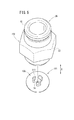
管継手100は、例えば、ステンレス等の金属製材料で形成され、略円筒形状を有するボディ102を備える。ボディ102は、流体圧機器14に挿入される先端側に、ねじ部20から連続しテーパ部を介して縮径する小径端部104を設ける。ボディ102の小径端部104には、オリフィス板(オリフィス部材)106が配設されるとともに、前記小径端部104と前記オリフィス板106とは、スナップフィット108により互いに接続される。
The pipe joint 100 is formed of, for example, a metal material such as stainless steel, and includes a
オリフィス板106は、例えば、POM(ポリアセタール)等の樹脂で形成され、中央部には、オリフィス74が形成される。オリフィス板106は、円板状を有するとともに、外方面(先端面)には、流体圧機器14のテーパ孔部18aの壁面に当接するテーパ部106aが形成される。
The
図4及び図5に示すように、オリフィス板106の内方面(裏面)には、スナップフィット108を構成する複数(例えば、3個)の爪部110が、オリフィス74を中心に等角度間隔ずつ離間して設けられる。各爪部110は、オリフィス板106の径方向に弾性変形可能である。
As shown in FIGS. 4 and 5, on the inner surface (rear surface) of the
図4に示すように、ボディ102の小径端部104内には、スナップフィット108を構成する複数(例えば、3個)の凹部(溝部)112が形成される。各凹部112は、各爪部110の位置に対応して設けられる。オリフィス板106の内方面と小径端部104の外周との間には、Oリング114が介装される。なお、図示しないが、それぞれ異なる開口径に設定されたオリフィス74を設けた複数のオリフィス板106が用意される。
As shown in FIG. 4, a plurality of (for example, three) recesses (grooves) 112 constituting the snap fit 108 are formed in the small
この第3の実施形態では、オリフィス板106とボディ102とは、スナップフィット108により互いに接続されている。このため、オリフィス板106をボディ102に対して容易且つ迅速に着脱させることができ、前記オリフィス板106の交換作業が一層効率的に遂行可能になる。
In this third embodiment, the
さらに、図6に示すように、管継手100が流体圧機器14に接続された状態では、オリフィス板106のテーパ部106aが流体圧機器14のテーパ孔部18aの壁面に当接している。従って、オリフィス板106の内方面は、ボディ102の小径端部104の先端面に当接し、クリアランスがなくなる。これにより、所望のシール機能を有することができ、ボディ102に専用のシール部材を設ける必要がない。
Furthermore, as shown in FIG. 6, in the state where the pipe joint 100 is connected to the
図7は、本発明の第4の実施形態に係る管継手120の全体縦断面図である。 FIG. 7 is an overall longitudinal sectional view of a pipe joint 120 according to a fourth embodiment of the present invention.
管継手120は、例えば、ステンレス等の金属製材料で形成され、略円筒形状を有するボディ122を備える。ボディ122は、ボディ16と略同様に構成されるとともに、流体通路24の先端部側には、第3段部124が設けられ、オリフィス部126が設けられる。
The pipe joint 120 is formed of, for example, a metal material such as stainless steel, and includes a
オリフィス部126は、流体通路24に位置して流体用チューブ12の先端と第3段部124との間に装着される樹脂製のオリフィス部材128を有する。オリフィス部材128は、図7及び図8に示すように、柱体部130の軸方向両端にリング部132a、132bが一体に設けられる。
The
図8に示すように、リング部132a、132bには、それぞれ外方に突出し且つ所定角度間隔ずつ離間して膨出部134a、134bが設けられる。膨出部134a、134bは、ボディ122の流体通路24を形成する内周面122aに圧入される。リング部132a、132bの外周と流体通路24の内周面122aとの間には、隙間136が形成される(図7参照)。
As shown in FIG. 8, the
オリフィス部材128の中央内部には、軸方向に沿ってオリフィス74が形成される。オリフィス74の両端側には、大径な孔部138a、138bが連通する。
An
オリフィス部材128の柱体部132には、ゴム製のパッキン部材140が外装される。パッキン部材140の外周には、流体通路24から流体用チューブ12側に向かって外方に傾斜しながら拡径する傾斜シール部142が設けられる。傾斜シール部142は、流体通路24の内周面122aに接触することにより、隙間136に沿って流体を矢印A1方向にのみ流通させ、矢印A2方向への流通を規制するチェック弁としての機能を有する。
A
この第4の実施形態では、オリフィス部材128がボディ122の内周面122aに圧入されており、前記オリフィス部材128の着脱作業が容易に遂行される。そして、図7に示すように、流体圧機器14からボディ122内に排出された流体は、隙間136を通って傾斜シール部142を内方に変形させ、流体用チューブ12内に排出される。
In the fourth embodiment, the
さらに、第4の実施形態では、図9に示すように、パッキン部材140は、反転姿勢でオリフィス部材128の柱体部130に装着することができる。このため、流体用チューブ12からボディ122内に供給された流体は、傾斜シール部142を内方に変形させることができ、隙間136を通って流体圧機器14に供給される。従って、パッキン部材140の取り付け姿勢を変換するだけで、流体の流れ方向を容易に変更させることが可能になる。
Furthermore, in the fourth embodiment, as shown in FIG. 9, the packing
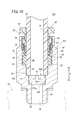
図10は、本発明の第5の実施形態に係る管継手150の全体縦断面図である。 FIG. 10 is an entire longitudinal cross-sectional view of a pipe joint 150 according to a fifth embodiment of the present invention.
管継手150は、例えば、ステンレス等の金属製材料で形成され、略円筒形状を有するボディ152を備える。ボディ152は、上記のボディ16と略同様に構成されており、第2段部34と第3段部124との間には、内周面152aが形成される。内周面152aには、流体用チューブ12の先端と第3段部124との間に挟持されて、樹脂製のオリフィス部材(オリフィス部)154が配設される。
The pipe fitting 150 is formed of, for example, a metal material such as stainless steel, and includes a
オリフィス部材154は、略円柱状を有し、外周部にはボディ152の内周面152aに摺接する凸部156が突出形成される。オリフィス部材154の中央部には、オリフィス74が流体用チューブ12側から所定の深さに形成され、前記オリフィス74には、大径な開口部158が連通する。
The
この第5の実施形態では、オリフィス部材154の形状が一層簡略化するとともに、前記オリフィス部材154を交換することにより、汎用性の向上が図られる。
In the fifth embodiment, the shape of the
図11は、本発明の第6の実施形態に係る管継手160の全体縦断面図である。なお、図10に示す第5の実施形態と同一の構成要素には、同一の参照符号を付して、その詳細な説明は省略する。 FIG. 11 is an entire longitudinal cross-sectional view of a pipe joint 160 according to a sixth embodiment of the present invention. The same components as those in the fifth embodiment shown in FIG. 10 are assigned the same reference numerals and detailed explanations thereof will be omitted.
管継手160は、流体圧機器14に接続される第1ボディ162と、流体用チューブ12が挿入される第2ボディ164とを備える。第1ボディ162は、例えば、ステンレス等の金属製材料で形成され、略円筒形状を有する。
The fitting 160 includes a
第2ボディ164は、例えば、ステンレス等の金属製材料で形成され、断面略L字状に屈曲形成される。第2ボディ164は、着脱機構26が組み込まれるボディ本体164aと前記ボディ本体164aの端部に屈曲形成され、且つ小径な管状部164bとを一体に有する。管状部164bは、第1ボディ162に挿入され、前記管状部164bの先端部と、第2段部34との間にオリフィス部材154が配置される。第1段部30には、管状部164bの外周に摺接してOリング166が配設される。
The
この第6の実施形態では、上記の第5の実施形態と同様の効果が得られるとともに、流体圧機器14に対して流体用チューブ12の挿入角度を変更させることができる。
In the sixth embodiment, the same effect as the fifth embodiment can be obtained, and the insertion angle of the
図12は、本発明の第7の実施形態に係る管継手170の全体縦断面図である。 FIG. 12 is an overall longitudinal sectional view of a pipe joint 170 according to a seventh embodiment of the present invention.
管継手170は、例えば、ステンレス等の金属製材料で形成され、略円筒形状を有するボディ172を備える。ボディ172内には、第3段部124と流体用チューブ12の先端との間に位置して、オリフィス部173が装着される。
The pipe joint 170 is formed of, for example, a metal material such as stainless steel, and includes a
図12及び図13に示すように、オリフィス部173は、樹脂製のオリフィス部材174を有する。オリフィス部材174は、リング部176aと前記リング部176aの一側面から膨出形成される段付き柱体部176bとを有する。
As shown in FIGS. 12 and 13, the
リング部176aの外周部には、所定数、例えば、3つの膨出部178が外方に突出して設けられる。各膨出部178は、ボディ172の内周面172aに圧入される。
A predetermined number of, for example, three bulging
段付き柱体部176bの中央部には、図12に示すように、大径な孔部180がリング部176a側から先端縁部に向かって形成される。この先端縁部には、小径なオリフィス74が形成される。段付き柱体部176bには、パッキン部材140が外装されるとともに、先端側には、樹脂製のリング部材182が取り付けられる。
As shown in FIG. 12, a
図13に示すように、リング部材182は、複数、例えば、3つの膨出部184が外方に突出して設けられ、各膨出部184は、ボディ172の内周面172aに圧入される。リング部材182の中央部には、略三角形状の開口部186が形成され、前記開口部186に段付き柱体部176bが圧入される。
As shown in FIG. 13, the
この第7の実施形態では、上記の第1〜第6の実施形態と同様の効果が得られる。 In the seventh embodiment, the same effects as those of the first to sixth embodiments can be obtained.
図14は、本発明の第8の実施形態に係る管継手190の全体縦断面図である。なお、第7の実施形態に係る管継手170と同一の構成要素には同一の参照符号を付して、その詳細な説明は省略する。 FIG. 14 is an overall longitudinal sectional view of a pipe joint 190 according to an eighth embodiment of the present invention. In addition, the same referential mark is attached | subjected to the same component as the pipe joint 170 which concerns on 7th Embodiment, and the detailed description is abbreviate | omitted.
管継手190は、第1ボディ192と第2ボディ194とを備え、全体として略L字状に屈曲する。第1ボディ192は、例えば、ステンレス等の金属製材料で形成され、略円筒形状を有する。
The pipe joint 190 includes a
第2ボディ194は、例えば、ステンレス等の金属製材料で形成され、着脱機構26が設けられるボディ本体部194aと、前記ボディ本体部194aの端部に略90°屈曲して形成される小径な管状部194bとを有する。管状部194bは、第1ボディ192にOリング166を介装して挿入され、先端部と第3段部124との間にオリフィス部173が配設される。
The
この第8の実施形態では、上記の第6の実施形態と同様に、流体圧機器14と流体用チューブ12との接続角度を変更させることができるという効果が得られる。
In the eighth embodiment, as in the sixth embodiment described above, the effect of being able to change the connection angle between the
図15は、本発明の第9の実施形態に係る管継手200の全体縦断面図である。 FIG. 15 is an entire longitudinal cross-sectional view of a pipe joint 200 according to a ninth embodiment of the present invention.
管継手200は、例えば、ステンレス等の金属製材料で形成され、略円筒形状を有するボディ202を備える。ボディ202内には、第2段部34と流体用チューブ12の先端部との間に位置して、例えば、真鍮、アルミニウム又は樹脂製のオリフィス部材(オリフィス部)204が配置される。
The pipe joint 200 is formed of, for example, a metal material such as stainless steel, and includes a
オリフィス部材204は、略円板状を有し、外周部には、ボディ202の内周面202aに摺接する凸部206が突出形成される。なお、内周面202aには、凸部206が嵌合するリング状凹部を設けてもよい。
The
この第9の実施形態では、上記の第1〜第8の実施形態と同様の効果が得られる。 In this ninth embodiment, the same effect as in the above first to eighth embodiments can be obtained.
図16は、本発明の第10の実施形態に係る管継手210の全体縦断面図である。 FIG. 16 is an overall longitudinal sectional view of a pipe joint 210 according to a tenth embodiment of the present invention.
管継手210は、例えば、ステンレス等の金属製材料で形成され、略円筒形状を有するボディ212を備える。ボディ212の内部には、オリフィス部214が設けられる。
The pipe fitting 210 is formed of, for example, a metal material such as stainless steel, and includes a
オリフィス部214は、図16及び図17に示すように、流体用チューブ12の先端部内周側に装着される樹脂製の筒状部材216を備える。筒状部材216は、流体用チューブ12に挿入される先端(天板部)側に開口部218が形成される。筒状部材216の外周には、流体用チューブ12の内周面に摺接する凸部220が周回形成される。
As shown in FIGS. 16 and 17, the
筒状部材216は、流体用チューブ12の先端側にフランジ部222が設けられ、前記フランジ部222には、傾斜面222aが形成される。フランジ部222側には、樹脂製の底板224が圧入される。底板224は、略リング状を有し、中心側には、筒状部材216の内方に膨出する係止部224aが形成される。
The
筒状部材216内には、樹脂製のオリフィス部材226が軸方向(矢印A方向)に進退可能に配置される。オリフィス部材226は、筒状部材216の内周面に摺動自在に配置されるリング状の摺動部226aを有し、前記摺動部226aには、複数の橋架部226bを介して球状部226cが一体成形される。球状部226cは、筒状部材216の開口部218を閉塞自在であり、中央部には、オリフィス74が形成される。
In the
この第10の実施形態では、図16に示すように、流体圧機器14から排出された流体は、矢印方向に沿ってボディ212に排出される。従って、オリフィス部材226は、圧力差によって筒状部材216の内方に移動し、球状部226cが開口部218を形成する周面に接触する。このため、ボディ212に導入された流体は、オリフィス部材226のオリフィス74のみを通って流れが制御された後、流体用チューブ12に排出される。
In the tenth embodiment, as shown in FIG. 16, the fluid discharged from the
一方、図18に示すように、流体用チューブ12から流体が供給されると、この流体は、オリフィス部材226を矢印方向に押圧する。これにより、オリフィス部材226は、底板224の係止部224aに当接する。従って、流体用チューブ12を流通する流体は、オリフィス74の他、開口部218と球状部226cとの間を通って(自由流れ)流体圧機器14に供給される。
On the other hand, as shown in FIG. 18, when the fluid is supplied from the
また、第10の実施形態では、図19に示すように、オリフィス部材226を反転姿勢で配置することができる。このため、流体用チューブ12から流体が供給されると、オリフィス部材226は、圧力差によって底板224側に移動し、球状部226cが係止部224aに当接する。これにより、流体用チューブ12に供給されて矢印方向に移動する流体は、オリフィス74のみを通って流れを制御された後、流体圧機器14に供給される。
In the tenth embodiment, as shown in FIG. 19, the
さらにまた、図20に示すように、流体圧機器14から排出された流体は、ボディ212に導入されて、オリフィス部材226を筒状部材216の開口部218側に移動させる。従って、流体は、オリフィス74の他、球状部226cと係止部224aとの間隙を通って(自由流れ)流体用チューブ12に排出される。
Furthermore, as shown in FIG. 20, the fluid discharged from the
図21は、本発明の第11の実施形態に係る管継手230の全体縦断面図である。なお、第10の実施形態に係る管継手210と同一の構成要素には、同一の参照符号を付して、その詳細な説明は省略する。 FIG. 21 is a whole longitudinal cross-sectional view of a pipe joint 230 according to an eleventh embodiment of the present invention. The same components as those of the pipe joint 210 according to the tenth embodiment are designated by the same reference numerals, and the detailed description thereof will be omitted.
管継手230は、例えば、ステンレス等の金属製材料で形成され、略円筒形状を有するボディ232を備える。ボディ232内には、第2段部34及び第3段部124を介してオリフィス部234が配置される。
The pipe joint 230 is formed of, for example, a metal material such as stainless steel, and includes a
図21及び図22に示すように、オリフィス部234は、樹脂製の筒状部材236と樹脂製の天板238との間に、オリフィス部材226を軸方向(矢印A方向)に移動可能に配置する。筒状部材236は、一端部側に開口部240を設けるとともに、外周部には、ボディ232の内周面232aに摺接する凸部242がリング状に膨出形成される。筒状部材236の他端部側には、部分的に切り欠いた大径部244が設けられ、前記大径部244は、第2段部34に当接支持される。
As shown in FIGS. 21 and 22, the
天板238は、略リング状を有し、中央部に開口部246が設けられるとともに、前記開口部246を周回して突出部248が形成される。突出部248は、オリフィス部材226を構成する球状部226cが着座自在である。
The
オリフィス部材226は、図21に示す配置姿勢と、これとは反転姿勢、すなわち、球状部226cが開口部218側に配置される姿勢とに配置可能である。この第11の実施形態では、上記の第10の実施形態と同様に流体の流れが行われる。
The
なお、本発明に係る管継手は、上述の各実施形態に限らず、本発明の要旨を逸脱することなく、種々の構成を採り得ることはもちろんである。 The pipe joint according to the present invention is, of course, not limited to the above-described embodiments, and various configurations can be adopted without departing from the scope of the present invention.
Claims (1)
前記ボディには、前記チューブと前記流体圧機器とを連通させるオリフィス部が設けられるとともに、
前記オリフィス部は、前記ボディに対して交換可能な複数のオリフィス部材を備えるとともに、
前記各オリフィス部材には、それぞれ開口径の異なるオリフィスが設けられ、
前記オリフィス部材は、前記チューブの先端内周に挿入されるインナースリーブであり、
前記インナースリーブの外周部には、前記チューブの先端内周に対して摺接する突出部としての凸部が設けられ、
前記チューブは、前記凸部が前記チューブの先端内周に摺接している状態で、前記着脱機構の内周に挿入されることにより、前記着脱機構を介して前記ボディに装着され、
前記インナースリーブは、前記チューブの先端に当接するフランジ部を有するとともに、
前記フランジ部は、前記チューブの先端との接触部位が傾斜面に形成されることを特徴とする管継手。 A pipe joint including a body into which a tube is inserted, and an attaching / detaching mechanism provided inside the body and capable of attaching / detaching the tube, and connected to a fluid pressure device,
The body is provided with an orifice portion for communicating the tube and the fluid pressure device,
The orifice portion comprises a plurality of orifice members replaceable with respect to the body ;
Each of the orifice members is provided with orifices having different opening diameters,
The orifice member is an inner sleeve inserted in the inner circumference of the tip of the tube ,
Wherein the outer peripheral portion of the inner sleeve, projecting portions of the protrusions sliding contact is provided for the tip inner periphery of the tube,
The tube is mounted on the body via the attaching / detaching mechanism by being inserted into the inner periphery of the attaching / detaching mechanism in a state where the convex portion is in sliding contact with the inner periphery of the distal end of the tube .
The inner sleeve has a flange portion that abuts on the end of the tube.
The flange portion, the pipe joint contact portion between the tip of the tube, characterized in Rukoto formed on the inclined surface.
Applications Claiming Priority (3)
| Application Number | Priority Date | Filing Date | Title |
|---|---|---|---|
| JP2012158035 | 2012-07-13 | ||
| JP2012158035 | 2012-07-13 | ||
| PCT/JP2013/068010 WO2014010452A1 (en) | 2012-07-13 | 2013-07-01 | Pipe joint |
Related Child Applications (1)
| Application Number | Title | Priority Date | Filing Date |
|---|---|---|---|
| JP2018213446A Division JP6748367B2 (en) | 2012-07-13 | 2018-11-14 | Pipe fitting |
Publications (2)
| Publication Number | Publication Date |
|---|---|
| JPWO2014010452A1 JPWO2014010452A1 (en) | 2016-06-23 |
| JP6503601B2 true JP6503601B2 (en) | 2019-04-24 |
Family
ID=49915916
Family Applications (3)
| Application Number | Title | Priority Date | Filing Date |
|---|---|---|---|
| JP2014524744A Active JP6503601B2 (en) | 2012-07-13 | 2013-07-01 | Pipe fitting |
| JP2014524745A Active JP6249237B2 (en) | 2012-07-13 | 2013-07-01 | Pipe fitting |
| JP2018213446A Active JP6748367B2 (en) | 2012-07-13 | 2018-11-14 | Pipe fitting |
Family Applications After (2)
| Application Number | Title | Priority Date | Filing Date |
|---|---|---|---|
| JP2014524745A Active JP6249237B2 (en) | 2012-07-13 | 2013-07-01 | Pipe fitting |
| JP2018213446A Active JP6748367B2 (en) | 2012-07-13 | 2018-11-14 | Pipe fitting |
Country Status (7)
| Country | Link |
|---|---|
| US (2) | US9689520B2 (en) |
| JP (3) | JP6503601B2 (en) |
| KR (2) | KR101682610B1 (en) |
| CN (2) | CN104541095B (en) |
| DE (2) | DE112013003524B4 (en) |
| TW (2) | TWI515384B (en) |
| WO (2) | WO2014010453A1 (en) |
Families Citing this family (24)
| Publication number | Priority date | Publication date | Assignee | Title |
|---|---|---|---|---|
| DE102012108791A1 (en) * | 2012-09-18 | 2014-03-20 | Voss Automotive Gmbh | Construction system for a connection device for media lines |
| JP6169422B2 (en) * | 2013-06-28 | 2017-07-26 | 株式会社ディスコ | Flow control device |
| WO2017073596A1 (en) * | 2015-10-30 | 2017-05-04 | 株式会社フジキン | Piping connection structure, piping connection tool, and piping connection method |
| US10609899B2 (en) * | 2016-07-29 | 2020-04-07 | Doskocil Manufacturing Company, Inc. | Baffle for an animal feeding device |
| CN106247044A (en) * | 2016-08-08 | 2016-12-21 | 北京航天试验技术研究所 | A kind of high-pressure gas flow controls device |
| US10281075B2 (en) | 2016-11-15 | 2019-05-07 | Campbell Fittings, Inc. | Quick disconnect coupling for conduit |
| CN106949333A (en) * | 2017-03-31 | 2017-07-14 | 中核核电运行管理有限公司 | A kind of ceramic chamber lining throttle orifice component of sherardizing steel |
| CN106939953A (en) * | 2017-03-31 | 2017-07-11 | 中核核电运行管理有限公司 | A kind of wear resistant filler lining throttle orifice component of sherardizing steel |
| WO2019087879A1 (en) * | 2017-10-31 | 2019-05-09 | 株式会社フジキン | Flow channel assembly and valve device |
| CN108061082B (en) * | 2017-12-12 | 2022-04-05 | 江苏骥坤新能源工程有限公司 | Water pump external connection type cluster jet device |
| CN108194736A (en) * | 2018-02-01 | 2018-06-22 | 日丰企业(佛山)有限公司 | Pipe fitting joint component |
| CN112088479A (en) * | 2018-05-08 | 2020-12-15 | 索尤若驱动有限及两合公司 | Electric machine with a rotor shaft, a first bearing and a second bearing |
| JP7041413B2 (en) * | 2018-05-14 | 2022-03-24 | Smc株式会社 | Pipe fittings |
| CN108895228A (en) * | 2018-08-23 | 2018-11-27 | 长沙格力暖通制冷设备有限公司 | A kind of discharge equipment |
| CN108825910B (en) * | 2018-08-24 | 2024-04-05 | 日丰企业(佛山)有限公司 | Capillary tube water diversion joint |
| EP3627022B1 (en) * | 2018-09-20 | 2022-12-21 | Danfoss A/S | Valve with presetting element |
| IT201900002529A1 (en) * | 2019-02-21 | 2020-08-21 | Giacomini Spa | VALVE FOR HYDRAULIC REGULATION AND BALANCING OF FLUID FLOW |
| KR102503059B1 (en) * | 2021-02-23 | 2023-02-23 | 쌍용자동차 주식회사 | Oil Chamber of Clutch for Automotive |
| CN216131550U (en) * | 2021-07-14 | 2022-03-25 | 胡涵 | Sealing cover with quick-plugging interface |
| CN113639119B (en) * | 2021-10-14 | 2021-12-10 | 启东市昶鑫环保设备有限公司 | Pipe fitting connecting device for drainer |
| CN113944667A (en) * | 2021-10-15 | 2022-01-18 | 厦门峻鸿环境固废处置有限公司 | Safety type self-disengaging garbage truck hydraulic oil pipe |
| US11493136B1 (en) * | 2021-10-25 | 2022-11-08 | conservalve, LLC | Discrete step, maximum flow-rate-selectable valve |
| EP4286728B1 (en) * | 2022-06-02 | 2024-05-01 | AVS, Ingenieur J.C. Römer GmbH | Insert |
| EP4286727B1 (en) * | 2022-06-02 | 2024-05-01 | AVS, Ingenieur J.C. Römer GmbH | Insert and method for producing an insert |
Family Cites Families (63)
| Publication number | Priority date | Publication date | Assignee | Title |
|---|---|---|---|---|
| US1682602A (en) * | 1924-04-05 | 1928-08-28 | Clarence A Dawley | Flow meter |
| US1617614A (en) * | 1924-08-18 | 1927-02-15 | York Victor | Flow nipple |
| US3148703A (en) * | 1961-12-15 | 1964-09-15 | Robertshaw Controls Co | Rotary pneumatic pressure divider |
| US3286731A (en) * | 1964-04-10 | 1966-11-22 | Perry Fay Company | Adjustable dampening device |
| US4011893A (en) | 1975-02-03 | 1977-03-15 | Clarence Bentley | Flow control valve |
| JPS51133631A (en) | 1975-05-16 | 1976-11-19 | Hitachi Ltd | Dash pot |
| JPS572783Y2 (en) * | 1976-07-09 | 1982-01-18 | ||
| JPS5918699B2 (en) | 1976-07-15 | 1984-04-28 | 三菱電機株式会社 | Electrostatic latent image development method |
| US4195631A (en) * | 1978-06-14 | 1980-04-01 | Baucom Keith K | Flow regulating device useable in plasma pheresis |
| JPS5753189U (en) | 1980-09-11 | 1982-03-27 | ||
| JPS59147173A (en) | 1983-02-10 | 1984-08-23 | Toa Valve Kk | Multi-stage throttling rotary valve |
| DE3603721C2 (en) | 1985-08-20 | 1994-11-17 | Smc Kk | Coupling for multiple passage line |
| US4738665A (en) * | 1985-09-27 | 1988-04-19 | Hall Hill Co. | Method and apparatus for controlling flow rate of fluid |
| JPH0326382Y2 (en) * | 1986-06-23 | 1991-06-07 | ||
| JPS6337896U (en) * | 1986-08-29 | 1988-03-11 | ||
| EP0268251B1 (en) * | 1986-11-18 | 1990-12-27 | Smc Corporation | Tube joint for use with multi-walled tube assembly |
| US4822344A (en) * | 1986-12-05 | 1989-04-18 | Sta-Set Corp. | Apparatus for controlling fluid flow rate |
| JPH0740103Y2 (en) | 1987-02-19 | 1995-09-13 | 株式会社ナブコ | Clutch master cylinder |
| FR2613445B1 (en) * | 1987-04-03 | 1991-07-05 | Caoutchouc Manuf Plastique | ELASTIC SUPPORT WITH INTEGRATED HYDRAULIC DAMPING WITH RIGID PARTITION WITH ADJUSTABLE LIQUID CIRCUIT |
| JPH0169697U (en) * | 1987-10-26 | 1989-05-09 | ||
| US5176360A (en) | 1988-03-14 | 1993-01-05 | Baxter International Inc. | Infusor having fixed and variable flow rate control mechanisms |
| JPH01169697U (en) * | 1988-05-20 | 1989-11-30 | ||
| JPH0326891U (en) * | 1989-07-27 | 1991-03-19 | ||
| FR2674602B1 (en) * | 1991-03-29 | 1993-10-01 | Bendix Europe Services Tech | FLOW RESTRICTOR. |
| US5287591A (en) | 1992-03-30 | 1994-02-22 | Racine Industries, Inc. | Carpet cleaning machine with convertible-use feature |
| FR2690497B1 (en) | 1992-04-23 | 1995-09-29 | Nikles Sarl | FLEXIBLE TUBE WITH FLOW REDUCER FOR HYDRAULIC SANITARY INSTALLATIONS. |
| JP2507219B2 (en) | 1992-07-02 | 1996-06-12 | 株式会社グランブルー | A squeezing valve in a diving respirator. |
| FR2697315A1 (en) | 1992-10-26 | 1994-04-29 | Nikles Sarl | Flow reducer for shower heads and similar devices - that can be fitted permanently to existing heads. |
| JPH06300150A (en) | 1993-02-18 | 1994-10-28 | Miyano:Kk | Pipe coupling with valve, check valve, and check valve structure |
| SI9500098A (en) | 1995-03-27 | 1996-10-31 | Rudi Belsak | Multipart water restrictor |
| JP3593382B2 (en) | 1995-04-13 | 2004-11-24 | Smc株式会社 | Pipe fittings |
| GB9512867D0 (en) * | 1995-06-23 | 1995-08-23 | Guest John D | Improvements in or relating to tube couplings |
| JPH1078165A (en) * | 1996-09-02 | 1998-03-24 | Fuji Electric Co Ltd | Variable aperture mechanism |
| DE19702173C1 (en) | 1997-01-23 | 1998-04-09 | Fluehs Drehtechnik Gmbh | Socket for gas-union |
| JP3466121B2 (en) | 1998-11-06 | 2003-11-10 | Smc株式会社 | Pneumatic cylinder with cushion mechanism |
| JP3372886B2 (en) * | 1999-02-18 | 2003-02-04 | エスエムシー株式会社 | Pipe fittings |
| JP3430242B2 (en) | 1999-02-18 | 2003-07-28 | Smc株式会社 | Check valve |
| JP3690236B2 (en) | 2000-03-17 | 2005-08-31 | 株式会社デンソー | ABS actuator |
| DE10154588B4 (en) | 2000-12-15 | 2013-01-17 | Schaeffler Technologies AG & Co. KG | Hydraulic system |
| FR2830071B1 (en) | 2001-09-21 | 2003-11-14 | Legris Sa | INSTANT CONNECTION DEVICE |
| DE10162657B4 (en) | 2001-12-20 | 2004-06-17 | Festo Ag & Co. | Connection piece for fluid lines and fluid technology device equipped with it |
| US6843507B2 (en) * | 2001-12-28 | 2005-01-18 | Smc Kabushiki Kaisha | Tube joint |
| JP2003194283A (en) * | 2001-12-28 | 2003-07-09 | Surpass Kogyo Kk | External orifice device |
| DE10208190B4 (en) * | 2002-02-20 | 2009-05-20 | Kludi Gmbh & Co. Kg | Shower hose with valve |
| JP2003254303A (en) | 2002-03-01 | 2003-09-10 | Smc Corp | Pneumatic cylinder with cushion function |
| JP3932398B2 (en) | 2002-03-18 | 2007-06-20 | Smc株式会社 | Pipe fitting |
| JP2004011855A (en) | 2002-06-10 | 2004-01-15 | Smc Corp | Cylinder with speed control mechanism |
| JP4110520B2 (en) | 2002-10-23 | 2008-07-02 | Smc株式会社 | Pipe fitting |
| JP3936322B2 (en) | 2003-10-07 | 2007-06-27 | 株式会社第一測範製作所 | Fixed throttle in air micrometer |
| FR2869088B1 (en) | 2004-02-16 | 2006-10-20 | Eco H2O Sarl | FEMALE FITTING FOR FLUID CONDUIT |
| JP4920453B2 (en) * | 2007-03-02 | 2012-04-18 | 幸次郎 島本 | Variable orifice device |
| DE112008003869B4 (en) * | 2008-06-12 | 2017-04-06 | Smc Corporation | pipe connectors |
| US20100122742A1 (en) * | 2008-11-20 | 2010-05-20 | Hsiao-Mei Lin | Fluid control throttle valve |
| JP2010185568A (en) * | 2009-01-14 | 2010-08-26 | Smc Corp | Pipe joint |
| JP2011033133A (en) | 2009-08-03 | 2011-02-17 | Toyo Keiki Co Ltd | Flow regulator |
| AU2010206066A1 (en) | 2009-08-03 | 2011-02-17 | Gsa Industries (Aust.) Pty. Ltd. | Pipe coupling |
| US9506592B2 (en) * | 2009-10-21 | 2016-11-29 | Brass-Craft Manufacturing Company | Supply stop with connection verification |
| JP5709096B2 (en) * | 2009-11-18 | 2015-04-30 | Smc株式会社 | Pipe fitting |
| EP2336625A3 (en) * | 2009-12-16 | 2011-09-21 | GSA Industries (Aust.) Pty Ltd | A tube coupling |
| US8658948B2 (en) * | 2009-12-17 | 2014-02-25 | Alcon Research, Ltd. | Docking station with temperature control and electronic identification system |
| JP5611699B2 (en) | 2010-07-28 | 2014-10-22 | 株式会社不二工機 | Multi-way selector valve |
| DE202012102342U1 (en) | 2012-06-26 | 2013-10-02 | Voss Automotive Gmbh | Connecting device for pipelines |
| EP2949984A4 (en) | 2012-11-07 | 2016-11-16 | Hita Technology Of Plastic System S L | Rapid-action coupling for pipes |
-
2013
- 2013-07-01 WO PCT/JP2013/068012 patent/WO2014010453A1/en active Application Filing
- 2013-07-01 DE DE112013003524.3T patent/DE112013003524B4/en active Active
- 2013-07-01 US US14/412,732 patent/US9689520B2/en active Active
- 2013-07-01 CN CN201380037452.0A patent/CN104541095B/en active Active
- 2013-07-01 WO PCT/JP2013/068010 patent/WO2014010452A1/en active Application Filing
- 2013-07-01 US US14/412,724 patent/US10151416B2/en active Active
- 2013-07-01 DE DE112013003519.7T patent/DE112013003519T5/en active Granted
- 2013-07-01 CN CN201380037502.5A patent/CN104487751B/en active Active
- 2013-07-01 JP JP2014524744A patent/JP6503601B2/en active Active
- 2013-07-01 KR KR1020157004023A patent/KR101682610B1/en active IP Right Grant
- 2013-07-01 KR KR1020157004022A patent/KR101739070B1/en active IP Right Grant
- 2013-07-01 JP JP2014524745A patent/JP6249237B2/en active Active
- 2013-07-11 TW TW102124870A patent/TWI515384B/en active
- 2013-07-11 TW TW102124872A patent/TWI518276B/en active
-
2018
- 2018-11-14 JP JP2018213446A patent/JP6748367B2/en active Active
Also Published As
| Publication number | Publication date |
|---|---|
| JPWO2014010453A1 (en) | 2016-06-23 |
| DE112013003524B4 (en) | 2023-04-27 |
| KR101739070B1 (en) | 2017-05-23 |
| JP2019044973A (en) | 2019-03-22 |
| CN104487751A (en) | 2015-04-01 |
| US20150145249A1 (en) | 2015-05-28 |
| US20150159799A1 (en) | 2015-06-11 |
| TWI515384B (en) | 2016-01-01 |
| WO2014010452A1 (en) | 2014-01-16 |
| KR20150036648A (en) | 2015-04-07 |
| US10151416B2 (en) | 2018-12-11 |
| KR101682610B1 (en) | 2016-12-05 |
| TW201418606A (en) | 2014-05-16 |
| TWI518276B (en) | 2016-01-21 |
| JPWO2014010452A1 (en) | 2016-06-23 |
| CN104541095B (en) | 2017-05-24 |
| KR20150036647A (en) | 2015-04-07 |
| JP6748367B2 (en) | 2020-09-02 |
| US9689520B2 (en) | 2017-06-27 |
| CN104487751B (en) | 2017-03-08 |
| DE112013003519T5 (en) | 2015-04-09 |
| DE112013003524T5 (en) | 2015-03-26 |
| CN104541095A (en) | 2015-04-22 |
| TW201408920A (en) | 2014-03-01 |
| WO2014010453A1 (en) | 2014-01-16 |
| JP6249237B2 (en) | 2017-12-20 |
Similar Documents
| Publication | Publication Date | Title |
|---|---|---|
| JP6503601B2 (en) | Pipe fitting | |
| CN105190054B (en) | Fluid pressure cylinder | |
| JP2008196518A (en) | Flow control valve | |
| JP5605954B2 (en) | Smooth bore dynamic center seal for spring brake actuator | |
| WO2016147869A1 (en) | Plastic oil supply port | |
| US10316983B2 (en) | Valve | |
| JP2015054385A (en) | Cutting tool | |
| JP4726749B2 (en) | Oil filter | |
| KR102045344B1 (en) | Hydraulic cylinder | |
| WO2010082550A1 (en) | Fluid pressure cylinder | |
| EP2472154B1 (en) | Flow rate control valve | |
| CN113631849A (en) | Rotary joint | |
| JP5746281B2 (en) | Fluid pressure cylinder | |
| JP2019537518A (en) | Shaft crimping tool | |
| JP6518762B2 (en) | Fluid pressure clamp device | |
| JP6106196B2 (en) | Integral power steering system | |
| WO2013038792A1 (en) | Mechanical seal | |
| JP2564802Y2 (en) | Rotary processing tools | |
| JP6527268B1 (en) | Rodless check valve | |
| JP2007125523A (en) | Inline type filter | |
| JP2006299870A (en) | Element replacement type filter | |
| JP2001317676A (en) | Tube joint for anti-condensation double tube |
Legal Events
| Date | Code | Title | Description |
|---|---|---|---|
| A621 | Written request for application examination |
Free format text: JAPANESE INTERMEDIATE CODE: A621 Effective date: 20160527 |
|
| A131 | Notification of reasons for refusal |
Free format text: JAPANESE INTERMEDIATE CODE: A131 Effective date: 20170404 |
|
| A521 | Request for written amendment filed |
Free format text: JAPANESE INTERMEDIATE CODE: A523 Effective date: 20170525 |
|
| A02 | Decision of refusal |
Free format text: JAPANESE INTERMEDIATE CODE: A02 Effective date: 20171031 |
|
| A521 | Request for written amendment filed |
Free format text: JAPANESE INTERMEDIATE CODE: A523 Effective date: 20180112 |
|
| A911 | Transfer to examiner for re-examination before appeal (zenchi) |
Free format text: JAPANESE INTERMEDIATE CODE: A911 Effective date: 20180119 |
|
| A912 | Re-examination (zenchi) completed and case transferred to appeal board |
Free format text: JAPANESE INTERMEDIATE CODE: A912 Effective date: 20180209 |
|
| A521 | Request for written amendment filed |
Free format text: JAPANESE INTERMEDIATE CODE: A523 Effective date: 20181114 |
|
| A61 | First payment of annual fees (during grant procedure) |
Free format text: JAPANESE INTERMEDIATE CODE: A61 Effective date: 20190307 |
|
| R150 | Certificate of patent or registration of utility model |
Ref document number: 6503601 Country of ref document: JP Free format text: JAPANESE INTERMEDIATE CODE: R150 |
|
| R250 | Receipt of annual fees |
Free format text: JAPANESE INTERMEDIATE CODE: R250 |
|
| R250 | Receipt of annual fees |
Free format text: JAPANESE INTERMEDIATE CODE: R250 |
|
| R250 | Receipt of annual fees |
Free format text: JAPANESE INTERMEDIATE CODE: R250 |