JP6502946B2 - Additional manufacturing apparatus and additional manufacturing method - Google Patents
Additional manufacturing apparatus and additional manufacturing method Download PDFInfo
- Publication number
- JP6502946B2 JP6502946B2 JP2016541505A JP2016541505A JP6502946B2 JP 6502946 B2 JP6502946 B2 JP 6502946B2 JP 2016541505 A JP2016541505 A JP 2016541505A JP 2016541505 A JP2016541505 A JP 2016541505A JP 6502946 B2 JP6502946 B2 JP 6502946B2
- Authority
- JP
- Japan
- Prior art keywords
- build
- plate
- fixture
- support
- additive manufacturing
- Prior art date
- Legal status (The legal status is an assumption and is not a legal conclusion. Google has not performed a legal analysis and makes no representation as to the accuracy of the status listed.)
- Active
Links
Images


Classifications
-
- B—PERFORMING OPERATIONS; TRANSPORTING
- B29—WORKING OF PLASTICS; WORKING OF SUBSTANCES IN A PLASTIC STATE IN GENERAL
- B29C—SHAPING OR JOINING OF PLASTICS; SHAPING OF MATERIAL IN A PLASTIC STATE, NOT OTHERWISE PROVIDED FOR; AFTER-TREATMENT OF THE SHAPED PRODUCTS, e.g. REPAIRING
- B29C64/00—Additive manufacturing, i.e. manufacturing of three-dimensional [3D] objects by additive deposition, additive agglomeration or additive layering, e.g. by 3D printing, stereolithography or selective laser sintering
- B29C64/30—Auxiliary operations or equipment
- B29C64/386—Data acquisition or data processing for additive manufacturing
-
- B—PERFORMING OPERATIONS; TRANSPORTING
- B22—CASTING; POWDER METALLURGY
- B22F—WORKING METALLIC POWDER; MANUFACTURE OF ARTICLES FROM METALLIC POWDER; MAKING METALLIC POWDER; APPARATUS OR DEVICES SPECIALLY ADAPTED FOR METALLIC POWDER
- B22F10/00—Additive manufacturing of workpieces or articles from metallic powder
- B22F10/20—Direct sintering or melting
- B22F10/28—Powder bed fusion, e.g. selective laser melting [SLM] or electron beam melting [EBM]
-
- B—PERFORMING OPERATIONS; TRANSPORTING
- B22—CASTING; POWDER METALLURGY
- B22F—WORKING METALLIC POWDER; MANUFACTURE OF ARTICLES FROM METALLIC POWDER; MAKING METALLIC POWDER; APPARATUS OR DEVICES SPECIALLY ADAPTED FOR METALLIC POWDER
- B22F12/00—Apparatus or devices specially adapted for additive manufacturing; Auxiliary means for additive manufacturing; Combinations of additive manufacturing apparatus or devices with other processing apparatus or devices
- B22F12/40—Radiation means
- B22F12/49—Scanners
-
- B—PERFORMING OPERATIONS; TRANSPORTING
- B22—CASTING; POWDER METALLURGY
- B22F—WORKING METALLIC POWDER; MANUFACTURE OF ARTICLES FROM METALLIC POWDER; MAKING METALLIC POWDER; APPARATUS OR DEVICES SPECIALLY ADAPTED FOR METALLIC POWDER
- B22F12/00—Apparatus or devices specially adapted for additive manufacturing; Auxiliary means for additive manufacturing; Combinations of additive manufacturing apparatus or devices with other processing apparatus or devices
- B22F12/50—Means for feeding of material, e.g. heads
- B22F12/52—Hoppers
-
- B—PERFORMING OPERATIONS; TRANSPORTING
- B23—MACHINE TOOLS; METAL-WORKING NOT OTHERWISE PROVIDED FOR
- B23P—METAL-WORKING NOT OTHERWISE PROVIDED FOR; COMBINED OPERATIONS; UNIVERSAL MACHINE TOOLS
- B23P6/00—Restoring or reconditioning objects
- B23P6/002—Repairing turbine components, e.g. moving or stationary blades, rotors
- B23P6/007—Repairing turbine components, e.g. moving or stationary blades, rotors using only additive methods, e.g. build-up welding
-
- B—PERFORMING OPERATIONS; TRANSPORTING
- B29—WORKING OF PLASTICS; WORKING OF SUBSTANCES IN A PLASTIC STATE IN GENERAL
- B29C—SHAPING OR JOINING OF PLASTICS; SHAPING OF MATERIAL IN A PLASTIC STATE, NOT OTHERWISE PROVIDED FOR; AFTER-TREATMENT OF THE SHAPED PRODUCTS, e.g. REPAIRING
- B29C64/00—Additive manufacturing, i.e. manufacturing of three-dimensional [3D] objects by additive deposition, additive agglomeration or additive layering, e.g. by 3D printing, stereolithography or selective laser sintering
- B29C64/10—Processes of additive manufacturing
- B29C64/141—Processes of additive manufacturing using only solid materials
- B29C64/153—Processes of additive manufacturing using only solid materials using layers of powder being selectively joined, e.g. by selective laser sintering or melting
-
- B—PERFORMING OPERATIONS; TRANSPORTING
- B29—WORKING OF PLASTICS; WORKING OF SUBSTANCES IN A PLASTIC STATE IN GENERAL
- B29C—SHAPING OR JOINING OF PLASTICS; SHAPING OF MATERIAL IN A PLASTIC STATE, NOT OTHERWISE PROVIDED FOR; AFTER-TREATMENT OF THE SHAPED PRODUCTS, e.g. REPAIRING
- B29C64/00—Additive manufacturing, i.e. manufacturing of three-dimensional [3D] objects by additive deposition, additive agglomeration or additive layering, e.g. by 3D printing, stereolithography or selective laser sintering
- B29C64/40—Structures for supporting 3D objects during manufacture and intended to be sacrificed after completion thereof
-
- B—PERFORMING OPERATIONS; TRANSPORTING
- B29—WORKING OF PLASTICS; WORKING OF SUBSTANCES IN A PLASTIC STATE IN GENERAL
- B29C—SHAPING OR JOINING OF PLASTICS; SHAPING OF MATERIAL IN A PLASTIC STATE, NOT OTHERWISE PROVIDED FOR; AFTER-TREATMENT OF THE SHAPED PRODUCTS, e.g. REPAIRING
- B29C73/00—Repairing of articles made from plastics or substances in a plastic state, e.g. of articles shaped or produced by using techniques covered by this subclass or subclass B29D
- B29C73/24—Apparatus or accessories not otherwise provided for
- B29C73/30—Apparatus or accessories not otherwise provided for for local pressing or local heating
- B29C73/34—Apparatus or accessories not otherwise provided for for local pressing or local heating for local heating
-
- B—PERFORMING OPERATIONS; TRANSPORTING
- B33—ADDITIVE MANUFACTURING TECHNOLOGY
- B33Y—ADDITIVE MANUFACTURING, i.e. MANUFACTURING OF THREE-DIMENSIONAL [3-D] OBJECTS BY ADDITIVE DEPOSITION, ADDITIVE AGGLOMERATION OR ADDITIVE LAYERING, e.g. BY 3-D PRINTING, STEREOLITHOGRAPHY OR SELECTIVE LASER SINTERING
- B33Y10/00—Processes of additive manufacturing
-
- B—PERFORMING OPERATIONS; TRANSPORTING
- B33—ADDITIVE MANUFACTURING TECHNOLOGY
- B33Y—ADDITIVE MANUFACTURING, i.e. MANUFACTURING OF THREE-DIMENSIONAL [3-D] OBJECTS BY ADDITIVE DEPOSITION, ADDITIVE AGGLOMERATION OR ADDITIVE LAYERING, e.g. BY 3-D PRINTING, STEREOLITHOGRAPHY OR SELECTIVE LASER SINTERING
- B33Y40/00—Auxiliary operations or equipment, e.g. for material handling
- B33Y40/20—Post-treatment, e.g. curing, coating or polishing
-
- F—MECHANICAL ENGINEERING; LIGHTING; HEATING; WEAPONS; BLASTING
- F01—MACHINES OR ENGINES IN GENERAL; ENGINE PLANTS IN GENERAL; STEAM ENGINES
- F01D—NON-POSITIVE DISPLACEMENT MACHINES OR ENGINES, e.g. STEAM TURBINES
- F01D25/00—Component parts, details, or accessories, not provided for in, or of interest apart from, other groups
- F01D25/28—Supporting or mounting arrangements, e.g. for turbine casing
- F01D25/285—Temporary support structures, e.g. for testing, assembling, installing, repairing; Assembly methods using such structures
-
- B—PERFORMING OPERATIONS; TRANSPORTING
- B22—CASTING; POWDER METALLURGY
- B22F—WORKING METALLIC POWDER; MANUFACTURE OF ARTICLES FROM METALLIC POWDER; MAKING METALLIC POWDER; APPARATUS OR DEVICES SPECIALLY ADAPTED FOR METALLIC POWDER
- B22F10/00—Additive manufacturing of workpieces or articles from metallic powder
- B22F10/60—Treatment of workpieces or articles after build-up
- B22F10/66—Treatment of workpieces or articles after build-up by mechanical means
-
- B—PERFORMING OPERATIONS; TRANSPORTING
- B22—CASTING; POWDER METALLURGY
- B22F—WORKING METALLIC POWDER; MANUFACTURE OF ARTICLES FROM METALLIC POWDER; MAKING METALLIC POWDER; APPARATUS OR DEVICES SPECIALLY ADAPTED FOR METALLIC POWDER
- B22F12/00—Apparatus or devices specially adapted for additive manufacturing; Auxiliary means for additive manufacturing; Combinations of additive manufacturing apparatus or devices with other processing apparatus or devices
- B22F12/40—Radiation means
- B22F12/44—Radiation means characterised by the configuration of the radiation means
-
- B—PERFORMING OPERATIONS; TRANSPORTING
- B22—CASTING; POWDER METALLURGY
- B22F—WORKING METALLIC POWDER; MANUFACTURE OF ARTICLES FROM METALLIC POWDER; MAKING METALLIC POWDER; APPARATUS OR DEVICES SPECIALLY ADAPTED FOR METALLIC POWDER
- B22F12/00—Apparatus or devices specially adapted for additive manufacturing; Auxiliary means for additive manufacturing; Combinations of additive manufacturing apparatus or devices with other processing apparatus or devices
- B22F12/50—Means for feeding of material, e.g. heads
- B22F12/58—Means for feeding of material, e.g. heads for changing the material composition, e.g. by mixing
-
- B—PERFORMING OPERATIONS; TRANSPORTING
- B22—CASTING; POWDER METALLURGY
- B22F—WORKING METALLIC POWDER; MANUFACTURE OF ARTICLES FROM METALLIC POWDER; MAKING METALLIC POWDER; APPARATUS OR DEVICES SPECIALLY ADAPTED FOR METALLIC POWDER
- B22F12/00—Apparatus or devices specially adapted for additive manufacturing; Auxiliary means for additive manufacturing; Combinations of additive manufacturing apparatus or devices with other processing apparatus or devices
- B22F12/60—Planarisation devices; Compression devices
- B22F12/67—Blades
-
- B—PERFORMING OPERATIONS; TRANSPORTING
- B22—CASTING; POWDER METALLURGY
- B22F—WORKING METALLIC POWDER; MANUFACTURE OF ARTICLES FROM METALLIC POWDER; MAKING METALLIC POWDER; APPARATUS OR DEVICES SPECIALLY ADAPTED FOR METALLIC POWDER
- B22F2998/00—Supplementary information concerning processes or compositions relating to powder metallurgy
- B22F2998/10—Processes characterised by the sequence of their steps
-
- B—PERFORMING OPERATIONS; TRANSPORTING
- B22—CASTING; POWDER METALLURGY
- B22F—WORKING METALLIC POWDER; MANUFACTURE OF ARTICLES FROM METALLIC POWDER; MAKING METALLIC POWDER; APPARATUS OR DEVICES SPECIALLY ADAPTED FOR METALLIC POWDER
- B22F5/00—Manufacture of workpieces or articles from metallic powder characterised by the special shape of the product
- B22F5/04—Manufacture of workpieces or articles from metallic powder characterised by the special shape of the product of turbine blades
-
- B—PERFORMING OPERATIONS; TRANSPORTING
- B29—WORKING OF PLASTICS; WORKING OF SUBSTANCES IN A PLASTIC STATE IN GENERAL
- B29C—SHAPING OR JOINING OF PLASTICS; SHAPING OF MATERIAL IN A PLASTIC STATE, NOT OTHERWISE PROVIDED FOR; AFTER-TREATMENT OF THE SHAPED PRODUCTS, e.g. REPAIRING
- B29C35/00—Heating, cooling or curing, e.g. crosslinking or vulcanising; Apparatus therefor
- B29C35/02—Heating or curing, e.g. crosslinking or vulcanizing during moulding, e.g. in a mould
- B29C35/08—Heating or curing, e.g. crosslinking or vulcanizing during moulding, e.g. in a mould by wave energy or particle radiation
- B29C35/0805—Heating or curing, e.g. crosslinking or vulcanizing during moulding, e.g. in a mould by wave energy or particle radiation using electromagnetic radiation
- B29C2035/0838—Heating or curing, e.g. crosslinking or vulcanizing during moulding, e.g. in a mould by wave energy or particle radiation using electromagnetic radiation using laser
-
- B—PERFORMING OPERATIONS; TRANSPORTING
- B29—WORKING OF PLASTICS; WORKING OF SUBSTANCES IN A PLASTIC STATE IN GENERAL
- B29L—INDEXING SCHEME ASSOCIATED WITH SUBCLASS B29C, RELATING TO PARTICULAR ARTICLES
- B29L2009/00—Layered products
-
- B—PERFORMING OPERATIONS; TRANSPORTING
- B33—ADDITIVE MANUFACTURING TECHNOLOGY
- B33Y—ADDITIVE MANUFACTURING, i.e. MANUFACTURING OF THREE-DIMENSIONAL [3-D] OBJECTS BY ADDITIVE DEPOSITION, ADDITIVE AGGLOMERATION OR ADDITIVE LAYERING, e.g. BY 3-D PRINTING, STEREOLITHOGRAPHY OR SELECTIVE LASER SINTERING
- B33Y30/00—Apparatus for additive manufacturing; Details thereof or accessories therefor
-
- B—PERFORMING OPERATIONS; TRANSPORTING
- B33—ADDITIVE MANUFACTURING TECHNOLOGY
- B33Y—ADDITIVE MANUFACTURING, i.e. MANUFACTURING OF THREE-DIMENSIONAL [3-D] OBJECTS BY ADDITIVE DEPOSITION, ADDITIVE AGGLOMERATION OR ADDITIVE LAYERING, e.g. BY 3-D PRINTING, STEREOLITHOGRAPHY OR SELECTIVE LASER SINTERING
- B33Y50/00—Data acquisition or data processing for additive manufacturing
- B33Y50/02—Data acquisition or data processing for additive manufacturing for controlling or regulating additive manufacturing processes
-
- F—MECHANICAL ENGINEERING; LIGHTING; HEATING; WEAPONS; BLASTING
- F01—MACHINES OR ENGINES IN GENERAL; ENGINE PLANTS IN GENERAL; STEAM ENGINES
- F01D—NON-POSITIVE DISPLACEMENT MACHINES OR ENGINES, e.g. STEAM TURBINES
- F01D5/00—Blades; Blade-carrying members; Heating, heat-insulating, cooling or antivibration means on the blades or the members
- F01D5/005—Repairing methods or devices
-
- Y—GENERAL TAGGING OF NEW TECHNOLOGICAL DEVELOPMENTS; GENERAL TAGGING OF CROSS-SECTIONAL TECHNOLOGIES SPANNING OVER SEVERAL SECTIONS OF THE IPC; TECHNICAL SUBJECTS COVERED BY FORMER USPC CROSS-REFERENCE ART COLLECTIONS [XRACs] AND DIGESTS
- Y02—TECHNOLOGIES OR APPLICATIONS FOR MITIGATION OR ADAPTATION AGAINST CLIMATE CHANGE
- Y02P—CLIMATE CHANGE MITIGATION TECHNOLOGIES IN THE PRODUCTION OR PROCESSING OF GOODS
- Y02P10/00—Technologies related to metal processing
- Y02P10/25—Process efficiency
Landscapes
- Engineering & Computer Science (AREA)
- Chemical & Material Sciences (AREA)
- Materials Engineering (AREA)
- Mechanical Engineering (AREA)
- Manufacturing & Machinery (AREA)
- Physics & Mathematics (AREA)
- Optics & Photonics (AREA)
- General Engineering & Computer Science (AREA)
- General Health & Medical Sciences (AREA)
- Plasma & Fusion (AREA)
- Toxicology (AREA)
- Health & Medical Sciences (AREA)
- Powder Metallurgy (AREA)
Description
本発明は、付加製造装置および付加製造方法に関する。詳細には、本発明は、限定しないが、付加製造プロセスを用いて、予め形成された部品の上で材料を直接固化させることにより、予め形成された部品を補う、または修復する装置および方法に適用される。 The present invention relates to an additive manufacturing apparatus and an additive manufacturing method. In particular, the present invention relates to an apparatus and method for supplementing or repairing pre-formed parts by directly solidifying material on pre-formed parts using, but not limited to, additive manufacturing processes. Applied.
選択的レーザ溶解/焼結(SLM/SLS)などの付加製造を用いて、タービンブレードなどの部品を修復することが望ましい。そのような修復を実行するためには、レーザビーム用に必要な走査経路が決定され得るように、ブレードは、付加製造装置の構築チャンバ(build chamber)内に既知の位置で装着されなければならない。 It is desirable to repair parts such as turbine blades using additive manufacturing such as selective laser melting / sintering (SLM / SLS). In order to perform such a repair, the blade must be mounted at a known position in the build chamber of the add-on manufacturing device so that the required scanning path for the laser beam can be determined. .
本発明の第1の態様によれば、部品を製造または修復する方法であって、部品を保持する固定具(fixture)を、付加製造装置を用いて構築するステップであって、材料は、エネルギービームを用いて固化され、固定具は、付加製造装置内の設定位置に保持された構築プレート(build plate)上に構築される、ステップと、部品を固定具に装着するステップと、固定具および部品が構築プレートに取り付けられた状態の構築プレートが、実質的に設定位置に保持されたときに、付加製造装置に、部品の上で材料を固化させるステップとを含む、部品を製造または修復する方法が提供される。 According to a first aspect of the invention, there is provided a method of manufacturing or repairing a part, the step of constructing a fixture for holding the part using an additive manufacturing device, wherein the material is energy Solidifying with a beam, the fixture being constructed on a build plate held in a set position in the additive manufacturing device, the steps of mounting the part on the fixture, the fixture and Manufacturing or repairing the part, including the additional manufacturing apparatus solidifying material on the part when the build plate with the part attached to the build plate is substantially held in the set position A method is provided.
固定具は付加製造装置を用いて製造されているため、エネルギービームの座標系に対する固定具の位置は既知である。したがって、部品の幾何形状が既知であり、固定具に対する部品の位置が既知であり、かつ、固定具が、それが形成された位置と実質的に同じ設定位置にとどまる/位置する場合、部品上で材料を固化させるエネルギービーム用の走査経路は、固定具を生成するために使用されたデータから決定されることができる。この方法では、エネルギービーム座標系と部品との整合が容易となり得る。 Since the fixture is manufactured using an additive manufacturing device, the position of the fixture relative to the energy beam's coordinate system is known. Thus, if the geometry of the part is known, the position of the part relative to the fastener is known, and the fastener remains / located at substantially the same set position as it was formed on the part The scan path for the energy beam that solidifies the material at can be determined from the data used to generate the fixture. This method may facilitate alignment of the energy beam coordinate system with the part.
部品の幾何形状は、部品を測定することにより決定されることができる。例えば、部品は、座標測定機の接触プローブを用いて測定されることができる。あるいは、部品の幾何形状は、CADまたはSTLモデルなどの幾何形状データから知ることができる。 The geometry of the part can be determined by measuring the part. For example, the part can be measured using the contact probe of a coordinate measuring machine. Alternatively, the geometry of the part can be known from geometry data such as CAD or STL models.
本方法は、部品および固定具を測定し、固定具に対する部品の位置を決定するステップと、決定された固定具に対する部品の位置から、エネルギービーム用の走査経路を決定するステップと、決定された走査経路に沿ってエネルギービームを向け、部品の上で材料を固化させるステップとを含むことができる。 The method comprises the steps of measuring the part and the fixture and determining the position of the part relative to the fixture, and determining the scanning path for the energy beam from the determined position of the part relative to the fixture Directing an energy beam along a scanning path to solidify the material on the part.
あるいは、固定具は、部品が、予め決定された位置で固定具内に装着されることを確実にする構成を備えることができる。そのような実施形態では、部品の測定は不要となり得、部品上で材料を固化させるために用いられる走査経路は、部品が、予め決定された位置に装着されているという仮定に基づくものとすることができる。 Alternatively, the fastener can be provided with a configuration that ensures that the component is mounted in the fastener at a predetermined position. In such embodiments, measurement of the part may not be necessary, and the scanning path used to solidify the material on the part will be based on the assumption that the part is mounted at a predetermined position be able to.
構築プレートは、付加製造装置の構築チャンバ内に取り外し可能に配置可能とすることができる。構築プレートは、構築チャンバ内に配置された装着構成(mounting formations)に相補的な装着構成を備えることができ、構築チャンバ内の繰り返し可能な位置への構築プレートの装着が可能となる。装着構成は、動的装着(kinematic mount)を形成することができる。動的装着は、6自由度の構築プレートの位置を拘束することができる。この方法では、構築プレートは、部品および固定具の測定のために装置から取り外され、そして、装着構成の係合を通し、装置内の設定位置に戻されることができる。構築プレートおよび/または装着構成は、構築チャンバ内の構築プレートの装着を単一の方向へ拘束するように配設されることができる。取り外し、そして再挿入した後に、固定具が取り付けられた構築プレートが、以前と実質的に同じ位置に位置し、固定具の位置が、固定具を形成する際に用いた座標系に対し既知でありさえすれば、構築チャンバ内の構築プレートの位置を知ることが不要となり得る。 The build plate may be removably positionable within the build chamber of the add-on manufacturing device. The build plate can be provided with a mounting configuration complementary to the mounting formations located in the build chamber, allowing mounting of the build plate to repeatable locations within the build chamber. The mounting arrangement can form a kinematic mount. Dynamic mounting can constrain the position of the build plate in six degrees of freedom. In this way, the build plate can be removed from the device for measurement of parts and fixtures, and can be returned to a set position in the device through engagement of the mounting configuration. The build plate and / or the mounting configuration can be arranged to constrain the mounting of the build plate in the build chamber in a single direction. After removal and reinsertion, the construction plate to which the fixture is attached is located in substantially the same position as before and the location of the fixture is known relative to the coordinate system used in forming the fixture If so, it may not be necessary to know the position of the build plate in the build chamber.
本方法は、STLモデルなどの固定具モデルに基づき固定具を構築するステップと、測定するステップ中に得た測定データおよび固定具モデルから、組み合わされた固定具および部品モデルを生成するステップと、そして、組み合わされた固定具および部品モデルから、走査経路を決定するステップと、を含むことができる。本方法は、固定具上のデータム形体(datum features)を測定するステップと、データム形体に対する測定データを用いて、測定データと固定具モデルとを(ソフトウェア内で)整合させるステップとを含むことができる。走査経路は、整合後の測定データから決定されることができる。 The method comprises building a fixture based on a fixture model, such as a STL model, and generating combined fixture and part models from the measured data obtained during the measuring step and the fixture model. And determining the scan path from the combined fixture and part model. The method includes measuring the datum features on the fixture and aligning the measurement data with the fixture model (in software) using the measurement data for the datum features. it can. The scan path can be determined from the measured data after alignment.
部品に対する測定データは、基準部品モデル(nominal part model)と比較されることができ、走査経路は、測定データと基準部品モデルとの間の差異に基づき材料を固化させるように決定される。例えば、このような方法は、部品の摩耗領域を改修するなど、部品を修理するために用いられることができる。 Measurement data for the part may be compared to a nominal part model, and a scan path is determined to solidify the material based on the difference between the measurement data and the reference part model. For example, such a method can be used to repair a part, such as repairing a worn area of the part.
本方法は、単一の付加製造装置内で、複数の部品に対し、同時に実行されることができる。例えば、本方法は、単一の構築プレート上に複数の固定具を構築するステップであって、それぞれの固定具が、部品のうちの少なくとも1つを保持する、ステップと、固定具内に部品を装着するステップと、少なくとも1つの部品および固定具のそれぞれの組合せを測定し、固定具に対する少なくとも1つの部品の位置を決定するステップと、固定具に対する少なくとも1つの部品の位置から、エネルギービーム用の走査経路を決定するステップと、固定具および少なくとも1つの部品が構築プレートに取り付けられた状態の構築プレートが、実質的に設定位置に保持されたときに、走査経路に沿ってエネルギービームを向けることにより、付加製造装置に、少なくとも1つの部品の上で材料を固化させるステップとを含むことができる。 The method can be performed simultaneously on multiple parts in a single additive manufacturing device. For example, the method comprises constructing a plurality of fasteners on a single build plate, wherein each fastener holds at least one of the parts, and the components in the fasteners. Mounting the at least one component and measuring each combination of the at least one component and the fixture to determine the position of the at least one component relative to the fixture; and from the position of the at least one component relative to the fixture for the energy beam Determining the scan path of the light source, and directing the energy beam along the scan path when the build plate with the fixture and at least one component attached to the build plate is substantially held in the set position. Optionally, the adjunct manufacturing apparatus can include solidifying the material on at least one part.
固定具は、部品上の装着構成と係合する装着構成を備えることができる。装着構成は、部品上の相補的な凹部に圧入されるねじ、突出部(または、部品上の突出部が圧入される凹部)等を備えることができる。 The fastener may comprise a mounting arrangement for engaging a mounting arrangement on the component. The mounting arrangement may comprise a screw, a protrusion (or a recess into which the protrusion on the part is press-fit), etc., which are press-fit into complementary recesses on the part.
本発明の第2の態様によれば、付加製造装置のエネルギービーム用の走査経路を決定する方法であって、部品および固定具の測定データを、部品が固定具内に装着されたときに受信するステップであって、固定具は、付加製造装置を用いて構築され、材料は、エネルギービームを用いて固化され、固定具は、付加製造装置内の設定位置に保持された構築プレート上に構築される、ステップと、測定データから、固定具に対する部品の位置を決定するステップと、固定具に装着された部品が、構築プレートが設定位置にある付加製造装置内に配置されたときに、部品の上で材料を固化させるエネルギービーム用の走査経路を決定するステップであって、走査経路は、固定具に対する部品の位置から決定される、ステップとを含む方法が提供される。 According to a second aspect of the invention, there is provided a method of determining a scanning path for an energy beam of an additive manufacturing device comprising: receiving measurement data of a component and a fixture when the component is mounted in the fixture The fixture is constructed using the additive manufacturing device, the material is solidified using an energy beam, and the fastener is constructed on a build plate held in a set position within the additive manufacturing device The steps of determining the position of the component relative to the fixture from the measured data, and when the component mounted on the fixture is placed in the add-on manufacturing device with the build plate in the set position Determining a scanning path for the energy beam which solidifies the material on the surface, wherein the scanning path is determined from the position of the part relative to the fixture. .
本発明の第3の態様によれば、データキャリアであって、その上に指示を有し、この指示は、プロセッサにより実施されるとき、プロセッサに本発明の第2の態様の方法を実行させるデータキャリアが提供される。 According to a third aspect of the invention, a data carrier, having instructions thereon, which when executed by the processor causes the processor to perform the method of the second aspect of the invention A data carrier is provided.
本発明の上記態様のデータキャリアは、例えば、フロッピーディスク、CD−ROM、DVD−ROM/RAM(−R/−RWおよび+R/+RWを含む)、HD DVD、Blu Ray(商標)ディスク、メモリ(メモリスティック(商標)、SDカード、コンパクトフラッシュカード等)、ディスクドライブ(ハードディスクドライブなど)、テープ、任意の磁気/光学記憶装置などの非一時的データキャリア、あるいは、例えば、有線もしくは無線ネットワーク(インターネットダウンロード、FTP転送等)上で送信される信号などの、有線もしくは光ファイバー上の信号または無線信号などの一時的データキャリアなど、機器に指示を提供するのに適する媒体とすることができる。 The data carrier according to the above aspect of the present invention is, for example, a floppy disk, a CD-ROM, a DVD-ROM / RAM (including -R / -RW and + R / + RW), an HD DVD, a Blu RayTM disc, a memory ( Memory Stick (trademark), SD card, compact flash card etc.), disk drive (hard disk drive etc.), tape, non-temporary data carrier such as optional magnetic / optical storage, or eg wired or wireless network (Internet It may be a suitable medium for providing instructions to the device, such as a temporary data carrier such as a signal on wired or optical fiber, such as a signal transmitted on a download, an FTP transfer, etc.) or a wireless signal.
本発明の第4の態様によれば、一層ずつ3次元物体を形成する付加製造装置であって、構築支持体であって、その上に取り外し可能なベースプレート(base plate)が装着可能である、構築支持体と、取り外し可能なベースプレートが構築支持体上に装着されたときに、取り外し可能なベースプレートにわたって材料を層状に形成する材料分注機と、取り外し可能なベースプレート上に形成された材料の層の上にエネルギービームを向ける光モジュールとを備え、構築支持体は、ベースプレートが構築支持体上の繰り返し可能な位置に装着可能となるように、ベースプレート上の装着構成と連携可能な装着構成を備える、付加製造装置が提供される。 According to a fourth aspect of the present invention there is provided an added manufacturing apparatus for forming a three-dimensional object layer by layer, wherein the construction support is mountable with a removable base plate. A construction support, a material dispenser forming layers of material over the removable base plate when the removable base plate is mounted on the construction support, and a layer of material formed on the removable base plate And an optical module to direct the energy beam on top, the construction support comprising an attachment configuration cooperable with the attachment configuration on the base plate such that the base plate can be attached at repeatable locations on the construction support An additional manufacturing device is provided.
装着構成は、6自由度のベースプレートの位置を拘束する動的装着構成とすることができる。動的構成は、3対のボールおよびローラなどの3対の相補的な構成を備えることができる。 The mounting configuration may be a dynamic mounting configuration that constrains the position of the base plate in six degrees of freedom. The dynamic configuration can comprise three pairs of complementary configurations, such as three pairs of balls and rollers.
本発明の第5の態様によれば、本発明の第4の態様による付加製造装置内に装着する構築プレートであって、ベースプレートが構築支持体上の繰り返し可能な位置に装着可能となるように、構築支持体上の装着構成と連携可能な装着構成を備える構築プレートが提供される。 According to a fifth aspect of the invention, there is provided a construction plate for mounting in an additive manufacturing apparatus according to the fourth aspect of the invention, wherein the base plate can be mounted at repeatable locations on the construction support. There is provided a build plate comprising a mounting arrangement cooperable with a mounting arrangement on a construction support.
図1、図2aおよび図2bを参照すると、本発明の実施形態による付加製造装置は、構築チャンバ101を備え、構築チャンバ101は、その中に構築空間116を規定する仕切り114、115と、上に粉体が堆積され得る表面とを有する。構築支持体102は、物体103が、選択的レーザ溶解粉体104により構築される作業領域を規定する。構築支持体102は、物体103の連続する層が形成されるにつれて、機構117を用いて構築空間116内で下降されることができる。使用可能な構築空間は、構築支持体102が構築空間116内に下降され得る範囲により規定される。粉体104の層は、粉体ホッパー(powder hopper)125と、計量デバイス127と、ワイパ126とを備える分注装置により、物体103が構築されるときに形成される。例えば、計量デバイス127は、特許文献1に記載されるようなものとすることができる。レーザモジュール105は、粉体104を溶解するレーザを生成し、このレーザは、コンピュータ118の制御下で、必要に応じて光学モジュール106により粉体床104上に向けられる。レーザは、窓107を介してチャンバ101に進入する。
Referring to FIGS. 1, 2a and 2b, an additive manufacturing apparatus according to an embodiment of the present invention comprises a
コンピュータ118は、プロセッサユニット119と、メモリ120と、光学モジュール106、レーザモジュール105などのレーザ溶解装置のモジュール、ならびに、分注装置および構築支持体102の動きを駆動するモーター(図示せず)へのデータ接続とを備える。コンピュータ118は、メモリ120に格納された走査指示に基づき、レーザユニット105、光学ユニット106、および構築プラットホーム(build platform)102の動きを制御する。
The
チャンバ101内には、扉(図示せず)が設けられ、そこから物体を取り外す。
In the
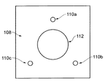
構築プレート108は、構築支持体102上に取り外し可能に装着される。構築支持体102および構築プレート108は、構築支持体102上の設定位置に構築プレート108を配置するために、相補的な装着構成109および110をそれぞれ備える。この実施形態では、装着構成109および110は、動的装着を形成する。具体的には、構築プレート108は、構築支持体102内の相補的な溝に係合するように配設された3つの離間されたボール110a、110b、および110cを備え、溝はそれぞれ、一対の平行な円柱109a、109b、および109cにより形成される。溝内のボールの係合は、6自由度の構築プレート108の位置を拘束する。
The
構築プレート108および構築支持体102上に磁石111、112が設けられ、構築プレート108は、磁石111、112の引力により構築支持体に向けて付勢される。
ここで、図3から図7を参照し、本発明の方法が説明される。装着構成109、110が係合され、構築プレート108を構築支持体102に対して設定位置に配置するように、構築プレート108が構築支持体102の上に装着される。構築支持体102の向きは、構築プレート108の表面が、構築プレート108にわたり粉体が散布される平面に確実に平行となるように調整されることができる。あるいは、ベースプレート108の平面とワイパが平行となるように、ワイパが調整されてもよい。
The method of the invention will now be described with reference to FIGS. 3 to 7. The
固定具200は、固定具の幾何学的モデル700に基づき、付加製造を用いてベースプレート108上に構築される。固定具200は、部品、この実施形態ではブレードを受け入れるスロット203と、ボルトを受け入れるように配設されたねじ穴202a、202b、202cの形態の、部品を固定具に留める手段とを備える。
The
固定具200が形成されると、構築プレート108から粉体が取り除かれ、部品300が、付加製造機内の固定具200内に装着される。図に示されたブレード300などの部品の修復の場合、ブレード300は、まず、修復に適する形状に加工されてもよい。例えば、部品は、固定具200内に装着されたときに、ワイパを用いて形成された材料の層の平面と整合する、部品300の直線上面を提供するために、ワイヤ放電加工(EDM)により修正されてもよい。加工は、構築プレートが設定位置に装着されたままの状態で、付加製造装置内で実行されることができる。あるいは、ベースプレート108は、部品300の加工および/または測定のために付加製造装置から取り外されてもよく、動的装着構成109、110は、固定具200が形成された構築支持体上の位置と実質的に同じ位置にベースプレート108を配置させるように、ベースプレート108が構築支持体102上に再装着されることを可能にする。
Once the
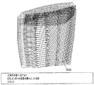
部品300および固定具200は、タッチトリガまたは走査接触プローブなどの測定プローブ400を用いて測定される。プローブは、Renishaw plcにより販売されているようなRevo 5−axis headなどの関着するヘッド、および/または、部品および固定具200の周りでプローブ400を移動させる座標測定機(CMM)上に装着されることができる。無数の測定点500が得られ(図5参照)、測定点500および固定具の既存のCADモデル700から、部品および固定具のCADモデル600が作成される。固定具200上のデータム点(datum points)の測定データから、部品モデルと固定具モデルとの整合が達成されることができる。
次いで、固定具と部品の組み合わされたCADモデル600が、部品を修復するために付加製造装置のレーザビームがとる走査経路を決定するために、ソフトウェアにインポートされる。例えば、測定データから決定されたモデルが、部品の理想/基準モデルと比較され、構築/再構築されるべき部品の部分を決定することができる。これらの部分が決定されると、少なくともこれらの部分が分割され、付加製造プロセスで形成される層を決定し、走査経路が各層に対して決定される。
The combined
固定具内に装着された部品は、付加製造装置内に配置される。部品の直線上面が、構築空間116の頂部と面一となるように、構築支持体102が下降される。構築空間116内に粉体が投入され、構築空間を満たす。次いで、付加製造装置が起動され、決定された走査経路に基づき、部品の上で材料を固化させる。
The components mounted in the fixture are placed in the add-on manufacturing device. The
本方法では、付加製造装置内で成長させられた固定具は、装置内で部品を既知の方向に整合させる手段を提供する。したがって、部品300と固定具200との間の相対的な位置が既知である限り、材料は、部品上で所望通りに固化されることができる。部品が、付加製造装置内に、装置を用いて製造されていない固定具により配置されていた場合、レーザビームを向ける光学モジュールの座標系に対する部品の場所を決定するために、別個の整合プロセスが実行されなければならないことになる。そのような整合プロセスは、複雑で時間のかかるものであろう。さらに、複数の部品が、単一の構築で修復/修正される場合、複数の固定具が必要となる。整合プロセスが実行されなければならない場合、それは、各部品上で別個に実行されなければならないであろう。本発明の方法を実行することにより、複数の固定具は、単一のベースプレート上で成長させられることができ、複数の部品が、単一の構築で修復/修正されることができる。
In the method, the fixture grown in the additive manufacturing device provides a means for aligning the parts in the device in a known direction. Thus, as long as the relative position between the
本明細書に規定された本発明から逸脱することなく、上述の実施形態に対する修正および改変が行われることができる。例えば、固定具は、固定具に対して既知の位置に部品を留めるように配設されることができる。そのような構成では、それらの相対的な位置を決定するために固定具および部品を測定することが不要になり得る。 Modifications and variations can be made to the above-described embodiments without departing from the invention as defined herein. For example, the fastener can be arranged to hold the part in a known position relative to the fastener. In such an arrangement, it may not be necessary to measure fixtures and parts to determine their relative position.
部品は、加工された部品が、既知の形状を有するように加工されることができる。したがって、構築される必要がある部分が、加工ステップから予め決定されているため、差異を見極めるために、加工された部品の測定された形状を基準形状と比較することが不要となり得る。したがって、部品の基準モデルから、かつ、部品が加工されたモデル上の既知の場所に基づき、部品を修復/修正する走査経路が決定されることができる。 The part can be processed so that the processed part has a known shape. Thus, it may not be necessary to compare the measured shape of the processed part with the reference shape in order to determine the differences, as the parts that need to be built are predetermined from the processing step. Thus, from the reference model of the part, and based on the known location on the model where the part was machined, a scan path for repairing / repairing the part can be determined.
ベースプレートが構築チャンバ内に繰り返し可能な様式で装着されることができないさらに別の構成では、犠牲固定具がベースプレート上に製造されることができ、ベースプレートは付加製造装置から取り外されない。次いで、部品が固定具内に装着され、固定具および部品が測定されることができる。次いで、犠牲固定具および部品のデータモデルが、測定値から形成されることができる。次いで、犠牲固定具と同一の別の固定具が、付加製造装置内に構築されることができる。別の固定具が取り付けられたベースプレートを付加製造装置から取り外すことなく、部品は、犠牲固定具から別の固定具へ移される。次いで、部品と別の固定具の組合せが、測定された部品と犠牲固定具の組合せと実質的に同じであるという仮定に基づき、材料が部品上で固化されることができる。材料が、複数の部品上で単一の構築で固化されることができるように、複数の部品が、単一の犠牲固定具で測定され、犠牲固定具に同一の複数の別の固定具が、単一のベースプレート上で成長させられることができる。 In yet another configuration where the base plate can not be mounted in a repeatable manner in the build chamber, the sacrificial fixture can be manufactured on the base plate and the base plate is not removed from the additive manufacturing device. The parts can then be mounted in the fixture and the fixtures and parts can be measured. A data model of the sacrificial fixtures and parts can then be formed from the measurements. Then, another fixture identical to the sacrificial fixture can be built into the additive manufacturing device. The components are transferred from the sacrificial fixture to the other fixture without removing the base plate to which the other fixture is attached from the add-on manufacturing device. The material can then be solidified on the part based on the assumption that the combination of the part and another fixture is substantially the same as the combination of the measured part and the sacrificial fixture. Multiple parts are measured with a single sacrificial fixture, and multiple separate fixtures identical to the sacrificial fixture, so that the material can be solidified in a single construction on multiple parts , Can be grown on a single base plate.
別の実施形態では、固定具は、動的装着特徴部を有して製造されることができ、部品が、固定具上の繰り返し可能な位置に装着されることが可能となる。 In another embodiment, the fastener can be manufactured with a dynamic attachment feature, which allows the parts to be attached in repeatable locations on the fastener.
例えば、固定具および部品の異なる要件を許容するために、固定具は、部品とは異なる材料で構築されることができる。 For example, the fasteners can be constructed of a different material than the components to allow for different requirements of the fasteners and components.
固定具および/または部品は、光学的に認識可能な特徴部を有して製造されることができ、固定具に対する部品の場所が、これらの光学的に認識可能な特徴部の場所から決定されることができる。例えば、付加製造装置は、固定具および部品を撮像する1または複数のカメラを備えることができ、固定具および部品の場所は、画像から決定されることができる。 The fasteners and / or parts can be manufactured with optically recognizable features, the location of the parts relative to the fasteners being determined from the location of these optically recognizable features Can be For example, the add-on manufacturing device can include one or more cameras that image fixtures and components, and the locations of fixtures and components can be determined from the image.
Claims (5)
構築支持体であって、その上に取り外し可能な構築プレートが装着可能である構築支持体と、
前記取り外し可能な構築プレートが前記構築支持体上に装着されたときに、前記取り外し可能な構築プレートにわたって材料を層状に形成する材料分注機と、
前記取り外し可能な構築プレート上に形成された材料の層の上にエネルギービームを向ける光モジュールと
を備え、前記構築支持体は、前記構築支持体上の繰り返し可能で6自由度の拘束された位置に前記構築プレートが装着可能となるように動的装着を成す装着構成であって、前記構築プレート上の装着構成と連携可能な装着構成、を備えていることを特徴とする付加製造装置。 An additive manufacturing apparatus for forming a three-dimensional object layer by layer, wherein
A construction support on which the removable construction plate is mountable,
A material dispenser that forms a layer of material across the removable build plate when the removable build plate is mounted on the build support;
Wherein a light module to direct an energy beam on a layer of removable material formed building plate, the construct support were constrained before Symbol repeatable and six degrees of freedom on the building support the construction plate is a mounting arrangement that forms a dynamically mounted so as to be mounted in position, the additional manufacturing apparatus characterized by comprising a mounting arrangement, which can cooperate with the mounting structure on the building plate.
Applications Claiming Priority (3)
| Application Number | Priority Date | Filing Date | Title |
|---|---|---|---|
| GB1322647.7 | 2013-12-20 | ||
| GBGB1322647.7A GB201322647D0 (en) | 2013-12-20 | 2013-12-20 | Additive manufacturing apparatus and method |
| PCT/GB2014/053817 WO2015092442A1 (en) | 2013-12-20 | 2014-12-22 | Additive manufacturing apparatus and method |
Publications (3)
| Publication Number | Publication Date |
|---|---|
| JP2017504501A JP2017504501A (en) | 2017-02-09 |
| JP2017504501A5 JP2017504501A5 (en) | 2017-11-24 |
| JP6502946B2 true JP6502946B2 (en) | 2019-04-17 |
Family
ID=50071196
Family Applications (1)
| Application Number | Title | Priority Date | Filing Date |
|---|---|---|---|
| JP2016541505A Active JP6502946B2 (en) | 2013-12-20 | 2014-12-22 | Additional manufacturing apparatus and additional manufacturing method |
Country Status (8)
| Country | Link |
|---|---|
| US (1) | US10618219B2 (en) |
| EP (1) | EP3084129B1 (en) |
| JP (1) | JP6502946B2 (en) |
| CN (1) | CN106030038B (en) |
| ES (1) | ES2741285T3 (en) |
| GB (1) | GB201322647D0 (en) |
| PL (1) | PL3084129T3 (en) |
| WO (1) | WO2015092442A1 (en) |
Families Citing this family (43)
| Publication number | Priority date | Publication date | Assignee | Title |
|---|---|---|---|---|
| GB0816308D0 (en) | 2008-09-05 | 2008-10-15 | Mtt Technologies Ltd | Optical module |
| US9289946B2 (en) * | 2013-02-01 | 2016-03-22 | Massachusetts Institute Of Technology | Automated three-dimensional printer part removal |
| GB201510220D0 (en) | 2015-06-11 | 2015-07-29 | Renishaw Plc | Additive manufacturing apparatus and method |
| US11358224B2 (en) | 2015-11-16 | 2022-06-14 | Renishaw Plc | Module for additive manufacturing apparatus and method |
| US11141809B2 (en) | 2015-12-04 | 2021-10-12 | Raytheon Company | Electron beam additive manufacturing |
| US11130191B2 (en) * | 2016-07-22 | 2021-09-28 | Hamilton Sundstrand Corporation | Method of manufacturing metal articles |
| FR3055564B1 (en) * | 2016-09-08 | 2020-07-31 | Safran | METHOD OF MANUFACTURING A PART IN ELECTROCONDUCTIVE MATERIAL BY ADDITIVE MANUFACTURING |
| US10908587B2 (en) * | 2016-10-27 | 2021-02-02 | Desprez Llc | Machine-assisted part design with automated design request interpretation |
| DE102016222555A1 (en) * | 2016-11-16 | 2018-05-17 | Siemens Aktiengesellschaft | Method for additive production of a component and computer-readable medium |
| CN109963685B (en) * | 2016-11-16 | 2022-04-29 | 康明斯有限公司 | System and method for adding material to castings |
| US11167454B2 (en) * | 2017-01-13 | 2021-11-09 | General Electric Company | Method and apparatus for continuously refreshing a recoater blade for additive manufacturing |
| DE102017201994A1 (en) * | 2017-02-08 | 2018-08-09 | Siemens Aktiengesellschaft | Method and apparatus for the powder bed-based additive construction of a plurality of similar components |
| EP3417961B1 (en) * | 2017-06-19 | 2022-07-27 | General Electric Company | Additive manufacturing fixture |
| US20190001658A1 (en) * | 2017-06-30 | 2019-01-03 | General Electric Company | Systems and method for advanced additive manufacturing |
| EP3431211B1 (en) * | 2017-07-20 | 2022-03-16 | General Electric Company | Method for manufacturing a hybrid article |
| CN110996820A (en) * | 2017-08-01 | 2020-04-10 | 华沙整形外科股份有限公司 | Spinal implant and method of making same |
| US11027368B2 (en) * | 2017-08-02 | 2021-06-08 | General Electric Company | Continuous additive manufacture of high pressure turbine |
| CN109774143A (en) * | 2017-11-13 | 2019-05-21 | 三纬国际立体列印科技股份有限公司 | The platform structure and its lamination microscope carrier of 3D printer |
| DE102018110742A1 (en) * | 2018-05-04 | 2019-11-07 | Liebherr-Werk Biberach Gmbh | Method and device for servicing and / or repairing a construction machine |
| US10814439B2 (en) * | 2018-05-31 | 2020-10-27 | General Electric Company | Turbomachine repair using additive manufacturing |
| US11440256B2 (en) | 2018-06-15 | 2022-09-13 | Howmedica Osteonics Corp. | Stackable build plates for additive manufacturing powder handling |
| EP3590630A1 (en) | 2018-07-02 | 2020-01-08 | Renishaw PLC | Acoustic emission sensing in powder bed additive manufacturing |
| CN110756800B (en) * | 2018-07-26 | 2022-02-01 | 中国商用飞机有限责任公司 | Additive manufacturing method |
| JP7169147B2 (en) | 2018-10-04 | 2022-11-10 | 株式会社Fuji | Three-dimensional modeling method |
| US11123833B2 (en) | 2018-12-18 | 2021-09-21 | Ford Motor Company | Adjustable fixture to position parts for dimensional measurement |
| US20200207040A1 (en) * | 2018-12-31 | 2020-07-02 | 3D Systems, Inc. | System and method for repairing a three-dimensional article |
| US11144034B2 (en) | 2019-01-30 | 2021-10-12 | General Electric Company | Additive manufacturing systems and methods of generating CAD models for additively printing on workpieces |
| US11344979B2 (en) | 2019-01-30 | 2022-05-31 | General Electric Company | Build plate clamping-assembly and additive manufacturing systems and methods of additively printing on workpieces |
| US11426799B2 (en) | 2019-01-30 | 2022-08-30 | General Electric Company | Powder seal assembly for decreasing powder usage in a powder bed additive manufacturing process |
| US11458681B2 (en) | 2019-01-30 | 2022-10-04 | General Electric Company | Recoating assembly for an additive manufacturing machine |
| US11407035B2 (en) | 2019-01-30 | 2022-08-09 | General Electric Company | Powder seal assembly for decreasing powder usage in a powder bed additive manufacturing process |
| US11498132B2 (en) | 2019-01-30 | 2022-11-15 | General Electric Company | Additive manufacturing systems and methods of calibrating for additively printing on workpieces |
| US11285538B2 (en) | 2019-01-30 | 2022-03-29 | General Electric Company | Tooling assembly and method for aligning components for a powder bed additive manufacturing repair process |
| US11173574B2 (en) | 2019-01-30 | 2021-11-16 | General Electric Company | Workpiece-assembly and additive manufacturing systems and methods of additively printing on workpieces |
| US20220088680A1 (en) * | 2019-01-30 | 2022-03-24 | General Electric Company | Additive manufacturing system and methods for repairing components |
| US11465245B2 (en) * | 2019-01-30 | 2022-10-11 | General Electric Company | Tooling assembly for magnetically aligning components in an additive manufacturing machine |
| US11198182B2 (en) | 2019-01-30 | 2021-12-14 | General Electric Company | Additive manufacturing systems and methods of additively printing on workpieces |
| EP3736110A1 (en) * | 2019-05-09 | 2020-11-11 | LayerWise NV | System for aligning laser system to a carrier plate |
| US11298884B2 (en) * | 2019-06-07 | 2022-04-12 | General Electric Company | Additive manufacturing systems and methods of pretreating and additively printing on workpieces |
| EP4017663A1 (en) | 2019-08-23 | 2022-06-29 | Indium Corporation | Thermally decomposing build plate for facile release of 3d printed objects |
| GB202018817D0 (en) | 2020-11-30 | 2021-01-13 | Renishaw Plc | Powder bed fusion apparatus and methods |
| WO2022182775A1 (en) * | 2021-02-23 | 2022-09-01 | Indium Corporation | Build plate with thermally decomposing top surface for facile release of 3d printed objects |
| US20220266343A1 (en) * | 2021-02-23 | 2022-08-25 | Indium Corporation | Thermally decomposing build plate with casting mold for facile release of 3d printed objects |
Family Cites Families (22)
| Publication number | Priority date | Publication date | Assignee | Title |
|---|---|---|---|---|
| US5134569A (en) * | 1989-06-26 | 1992-07-28 | Masters William E | System and method for computer automated manufacturing using fluent material |
| JPH0929848A (en) | 1995-07-20 | 1997-02-04 | Olympus Optical Co Ltd | Outsert molding and manufacture thereof |
| JP2000094529A (en) | 1998-09-22 | 2000-04-04 | Sony Corp | Molding method |
| DE19846478C5 (en) | 1998-10-09 | 2004-10-14 | Eos Gmbh Electro Optical Systems | Laser-sintering machine |
| DE19939616C5 (en) * | 1999-08-20 | 2008-05-21 | Eos Gmbh Electro Optical Systems | Device for the generative production of a three-dimensional object |
| CN1476362A (en) | 2000-11-27 | 2004-02-18 | �¼��¹�����ѧ | Method and apparatus for creating three-dimensional metal part using high-temp direct laser melting |
| US7275925B2 (en) | 2001-08-30 | 2007-10-02 | Micron Technology, Inc. | Apparatus for stereolithographic processing of components and assemblies |
| DE10342880A1 (en) * | 2003-09-15 | 2005-04-14 | Trumpf Werkzeugmaschinen Gmbh + Co. Kg | substrate plate |
| US7127309B2 (en) * | 2004-02-10 | 2006-10-24 | Stratasys, Inc. | Modeling apparatus with tray substrate |
| US7621733B2 (en) | 2005-09-30 | 2009-11-24 | 3D Systems, Inc. | Rapid prototyping and manufacturing system and method |
| WO2007069746A1 (en) * | 2005-12-16 | 2007-06-21 | Yoshihiro Watanabe | Article such as surfboard and production method thereof |
| DE102006044555A1 (en) * | 2006-09-21 | 2008-04-03 | Mtu Aero Engines Gmbh | repair procedures |
| JP4258567B1 (en) | 2007-10-26 | 2009-04-30 | パナソニック電工株式会社 | Manufacturing method of three-dimensional shaped object |
| GB0813242D0 (en) | 2008-07-18 | 2008-08-27 | Mcp Tooling Technologies Ltd | Powder dispensing apparatus and method |
| CN101585233B (en) * | 2009-06-24 | 2011-06-22 | 唐少林 | Ice-light solidifying quick forming device and using method thereof |
| EP2301741A1 (en) | 2009-09-28 | 2011-03-30 | Siemens Medical Instruments Pte. Ltd. | In-ear housing muffler or otoplastic |
| US9085980B2 (en) * | 2011-03-04 | 2015-07-21 | Honeywell International Inc. | Methods for repairing turbine components |
| JP2013067036A (en) | 2011-09-21 | 2013-04-18 | Keyence Corp | Three-dimensional shaping apparatus |
| FR2982182B1 (en) * | 2011-11-03 | 2013-11-15 | Snecma | INSTALLATION FOR MANUFACTURING PARTS BY SELECTIVE FUSION OF POWDER |
| DE102012008369A1 (en) | 2012-04-25 | 2013-10-31 | Airbus Operations Gmbh | Method for producing a fluid-carrying component by layered construction |
| ES2873179T3 (en) * | 2012-05-10 | 2021-11-03 | Renishaw Plc | Method of making an item |
| DE102012011217A1 (en) | 2012-06-06 | 2013-12-12 | Cl Schutzrechtsverwaltungs Gmbh | Device, used to make three-dimensional hybrid component, comprises supporting unit, applying unit, and radiation unit, where plate-like body is disposed on upper side of support, is formed as contoured plug holder and comprises recesses |
-
2013
- 2013-12-20 GB GBGB1322647.7A patent/GB201322647D0/en not_active Ceased
-
2014
- 2014-12-22 EP EP14828502.6A patent/EP3084129B1/en active Active
- 2014-12-22 PL PL14828502T patent/PL3084129T3/en unknown
- 2014-12-22 JP JP2016541505A patent/JP6502946B2/en active Active
- 2014-12-22 CN CN201480075890.0A patent/CN106030038B/en active Active
- 2014-12-22 US US15/105,976 patent/US10618219B2/en active Active
- 2014-12-22 WO PCT/GB2014/053817 patent/WO2015092442A1/en active Application Filing
- 2014-12-22 ES ES14828502T patent/ES2741285T3/en active Active
Also Published As
| Publication number | Publication date |
|---|---|
| WO2015092442A1 (en) | 2015-06-25 |
| JP2017504501A (en) | 2017-02-09 |
| ES2741285T3 (en) | 2020-02-10 |
| EP3084129B1 (en) | 2019-05-08 |
| PL3084129T3 (en) | 2019-08-30 |
| CN106030038A (en) | 2016-10-12 |
| GB201322647D0 (en) | 2014-02-05 |
| EP3084129A1 (en) | 2016-10-26 |
| US20160318257A1 (en) | 2016-11-03 |
| CN106030038B (en) | 2018-09-21 |
| US10618219B2 (en) | 2020-04-14 |
Similar Documents
| Publication | Publication Date | Title |
|---|---|---|
| JP6502946B2 (en) | Additional manufacturing apparatus and additional manufacturing method | |
| CN107037126B (en) | Acoustic monitoring method for additive manufacturing process | |
| JP7331015B2 (en) | Turbomachinery repair using additive manufacturing | |
| Kun | Reconstruction and development of a 3D printer using FDM technology | |
| JP2010513927A5 (en) | ||
| US9222769B2 (en) | High speed metrology with numerically controlled machines | |
| US20160121438A1 (en) | Repair method and device for the additive repair of a component | |
| JP6744398B2 (en) | Device for additionally producing a three-dimensional object | |
| CN104493493A (en) | Multi-axis milling and laser melting composite 3D printing apparatus | |
| JP2017504501A5 (en) | ||
| WO2009063088A3 (en) | Method for optical measurement of objects using a triangulation method | |
| JP2013006269A (en) | Robot fabricator | |
| US10442180B2 (en) | Systems and methods for additive manufacturing recoating | |
| CN204524771U (en) | Lf and laser milling compound 3D printing device | |
| JPWO2017110375A1 (en) | 3D processing equipment | |
| CN109940270A (en) | A kind of sevenfive axis ultrafast laser machining system | |
| CN104476196A (en) | Combined laser melting and laser milling 3D (three-Dimensional) printing equipment | |
| CN105841641A (en) | Laser triangulation method-based three-dimensional measuring instrument and flatness detection method | |
| CN104655024A (en) | Image measurement equipment as well as quick and accurate height measurement device and method of image measurement equipment | |
| KR101692141B1 (en) | Forming device for three-dimensional structure and forming method thereof | |
| US20120055912A1 (en) | Micro spherical stylus manufacturing machine | |
| CN107560563B (en) | A kind of calibration of line laser three-dimensional measuring apparatus and error compensating method | |
| JP2020181398A (en) | Waveform display device, and waveform display method | |
| US20180252520A1 (en) | Method for correcting coordinate measurement machine errors | |
| JP7251484B2 (en) | Machining system, machining method, computer program, recording medium and control device |
Legal Events
| Date | Code | Title | Description |
|---|---|---|---|
| A521 | Request for written amendment filed |
Free format text: JAPANESE INTERMEDIATE CODE: A523 Effective date: 20171012 |
|
| A621 | Written request for application examination |
Free format text: JAPANESE INTERMEDIATE CODE: A621 Effective date: 20171012 |
|
| A977 | Report on retrieval |
Free format text: JAPANESE INTERMEDIATE CODE: A971007 Effective date: 20181030 |
|
| A131 | Notification of reasons for refusal |
Free format text: JAPANESE INTERMEDIATE CODE: A131 Effective date: 20181113 |
|
| A521 | Request for written amendment filed |
Free format text: JAPANESE INTERMEDIATE CODE: A523 Effective date: 20190213 |
|
| TRDD | Decision of grant or rejection written | ||
| A01 | Written decision to grant a patent or to grant a registration (utility model) |
Free format text: JAPANESE INTERMEDIATE CODE: A01 Effective date: 20190312 |
|
| A61 | First payment of annual fees (during grant procedure) |
Free format text: JAPANESE INTERMEDIATE CODE: A61 Effective date: 20190322 |
|
| R150 | Certificate of patent or registration of utility model |
Ref document number: 6502946 Country of ref document: JP Free format text: JAPANESE INTERMEDIATE CODE: R150 |
|
| R250 | Receipt of annual fees |
Free format text: JAPANESE INTERMEDIATE CODE: R250 |
|
| R250 | Receipt of annual fees |
Free format text: JAPANESE INTERMEDIATE CODE: R250 |