JP6502415B2 - Egg container transfer device - Google Patents
Egg container transfer device Download PDFInfo
- Publication number
- JP6502415B2 JP6502415B2 JP2017081275A JP2017081275A JP6502415B2 JP 6502415 B2 JP6502415 B2 JP 6502415B2 JP 2017081275 A JP2017081275 A JP 2017081275A JP 2017081275 A JP2017081275 A JP 2017081275A JP 6502415 B2 JP6502415 B2 JP 6502415B2
- Authority
- JP
- Japan
- Prior art keywords
- egg
- container
- suction
- egg container
- containers
- Prior art date
- Legal status (The legal status is an assumption and is not a legal conclusion. Google has not performed a legal analysis and makes no representation as to the accuracy of the status listed.)
- Active
Links
Images


Description
本発明は、卵容器を移送する装置に関し、例えば、卵形状に沿った凹凸の蓋を有する容器を移送する装置に関する。 The present invention relates to an apparatus for transferring an egg container, for example, an apparatus for transferring a container having an uneven lid along an egg shape.
特許文献1は、包装容器の充填装置を開示している。この充填装置に、短軸ロボットである昇降部に複数の吸盤が配置されており、この吸盤が包装容器の平坦面の蓋を真空吸着して移送し箱詰めする。吸盤は包装容器の長辺の片側を保持するように位置決めされており、包装容器を持ち上げた際に、包装容器が傾くが吸盤が伸縮性を有することで保持可能にしている。また、卵の形状に合わせて凸状である蓋であっても吸盤が位置決めされていれば吸着可能であると記載されている。 Patent Document 1 discloses a filling device for packaging containers. In this filling device, a plurality of suction cups are disposed in the lifting and lowering unit which is a short-axis robot, and the suction cups vacuum-adsorb the lid of the flat surface of the packaging container to transfer and pack it. The suction cup is positioned so as to hold one side of the long side of the packaging container, and when the packaging container is lifted, the packaging container is inclined but can be held by the suction cup having elasticity. Moreover, even if it is a lid which is convex according to the shape of an egg, it is described that suction is possible if the suction cup is positioned.
しかしながら、特許文献1では、凸状の蓋に対して吸盤の位置決めを正確に行わなければならない。一方、鶏卵のサイズは、例えばMSからLLまであり、それらに合せて容器サイズ、すなわち凸間隔、凸サイズ、凸の天面の形状など多くの種類が存在する。つまり、箱詰めする鶏卵のサイズに応じて、特許文献1では吸盤の位置決めを行う必要がある。 However, in Patent Document 1, it is necessary to accurately position the suction cup with respect to the convex lid. On the other hand, the size of chicken eggs is, for example, from MS to LL, and there are many types according to them, such as container size, ie, convex interval, convex size, and shape of convex top surface. That is, in Patent Document 1, it is necessary to position the suction cups in accordance with the size of the packed chicken eggs.
近年、鶏卵生産工場は大規模化・自動化が進んでおり、大量の鶏卵を処理するための装置も高速化・多品種対応が要求されている。一方で、鶏卵の詰まった容器を箱詰めする装置において、現状では容器上面の平坦部分が大きな容器を吸盤で搬送したり、あるいは特許文献1のような卵サイズごとに吸盤の位置決めが必要な機構で対応するしかない。 In recent years, the egg production plant has been increased in scale and automated, and a device for processing a large amount of egg has also been required to speed up and cope with various varieties. On the other hand, in an apparatus for box-packing a container filled with chicken eggs, at present, a flat portion of the upper surface of the container transports a large container by suction cups, or a mechanism that requires positioning of suction cups for each egg size as in Patent Document 1 There is no choice but to respond.
そこで、本発明は、複数形状の容器、例えば、平坦蓋、サイズ違いの凸蓋の容器にも対応できる卵容器の移送装置を提供することを目的とする。 Then, an object of this invention is to provide the transfer apparatus of the egg container which can respond also to the container of a plurality of shapes, for example, the container of a flat lid and the convex lid of a different size.
本発明に係る卵容器移送装置は、
卵容器1つに対し少なくとも2つの吸着パッドを有する吸着部と、
前記吸着部に接続される吸引手段と、
前記吸着部が取り付けられる移送機構と、
前記卵容器と前記吸着部で吸着処理する場合に、前記吸引手段を制御する吸引制御部と、
前記移送機構の動きを制御する主制御部と、を備え、
前記吸着パッドは、
筒内部がエア吸引のために貫通した蛇腹筒状であり、および、
蛇腹筒状の長手方向長さより、蛇腹筒状または先端リップの外径が小さいことを特徴とする。
The egg container transfer device according to the present invention is
An adsorption unit having at least two adsorption pads for one egg container;
Suction means connected to the suction unit;
A transfer mechanism to which the suction unit is attached;
A suction control unit that controls the suction unit when suction processing is performed by the egg container and the suction unit;
A main control unit that controls the movement of the transfer mechanism;
The suction pad is
The inside of the tube is a bellows-like cylinder which is penetrated for air suction, and
It is characterized in that the outer diameter of the bellows cylindrical or tip lip is smaller than the longitudinal length of the bellows cylindrical.
本発明において、筒状の長手方向長さ(L)1に対する蛇腹筒状または先端リップの外径(Φ)が1未満であってもよく、例えば、L:Φ=1:0.1〜0.9、好ましくは1:0.3〜0.9、より好ましくは0.4〜0.8である。蛇腹筒状の長手方向長さ(L)を蛇腹筒状または先端リップの外径より長くすることで、卵容器の天面の凸状曲面に対応し変形できる。
また、別の言い方をすれば、筒状の長手方向長さ(L)が蛇腹筒状の外径(Φ)の1.1倍〜3.0倍、1.2倍〜2.5倍、1.3倍〜2.0倍であってもよい。
本発明において、蛇腹筒状の外径は、長手方向において一定であってもよく、先端リップほど大きくラッパ状になってもいてもよく、逆に小さくなってもいてもよい。
本発明において、前記蛇腹筒状の外径(Φ)は、蛇腹の複数段位置の平均値であってもよく、最大値、最小値であってもよい。
In the present invention, the outer diameter (Φ) of the bellows cylindrical or tip lip with respect to the cylindrical longitudinal length (L) 1 may be less than 1, for example, L: Φ = 1: 0.1-0. Preferably from 1: 0.3 to 0.9, more preferably from 0.4 to 0.8. By making the longitudinal direction length (L) of the bellows cylindrical shape longer than the outer diameter of the bellows cylindrical shape or the tip lip, it can be deformed corresponding to the convex curved surface of the top surface of the egg container.
Also, in other words, the longitudinal length (L) of the tubular is 1.1 times to 3.0 times, 1.2 times to 2.5 times the outer diameter (Φ) of the bellows tubular. It may be 1.3 times to 2.0 times.
In the present invention, the outer diameter of the bellows-like cylindrical shape may be constant in the longitudinal direction, may be as large as a trumpet like the tip lip, and may be smaller as it is.
In the present invention, the outer diameter (Φ) of the bellows cylindrical shape may be an average value of a plurality of steps of the bellows, or may be a maximum value or a minimum value.
本発明において、前記蛇腹は、1.5段ベローズ〜6.5段ベローズであってもよい。
前記蛇腹筒状の外径(Φ)は、例えば、20mm〜40mmである。
前記蛇腹筒状の長手方向長さ(L)は、例えば、30mm〜80mmである。
蛇腹筒状位置の厚み(T2)と、先端リップの厚み(T1)は、同じでもよく、先端リップの厚み(T1)の方が薄くてもよい。先端リップの厚み(T1)を薄くすることで、曲面に対する吸着が良くなる。
先端リップが、先端にいくほどその厚みが薄くなっていてもよい。これにより凸曲面や凸側面へ接触を好適に追随することができる。蛇腹筒状位置の厚み(T2)は、例えば、0.2mm〜2mmであり、先端リップの厚み(T1)は、例えば、0.1mm〜1mmである。
In the present invention, the bellows may be 1.5-step bellows to 6.5-step bellows.
The bellows-like outer diameter (Φ) is, for example, 20 mm to 40 mm.
The bellows-like longitudinal length (L) is, for example, 30 mm to 80 mm.
Bellows tubular position of the thickness (T2), the thickness of the end lip (T1) may be the same or may be thinner towards the thickness of the end lip (T 1). By reducing the thickness (T 1 ) of the tip lip, adsorption to the curved surface is improved.
The tip lip may be thinner as it goes to the tip. Thereby, contact can be suitably followed to a convex curve and a convex side. The thickness (T2) of the bellows cylindrical position is, for example, 0.2 mm to 2 mm, and the thickness (T1) of the tip lip is, for example, 0.1 mm to 1 mm.
本発明において、卵容器は、蓋と収載部を有し、蓋が平坦でもよく、卵の形状に沿った凸状の凸蓋であってもよい。
前記吸着パッドの先端リップは、卵容器の蓋の凸状の平坦部と同程度またはそれより小さい径であることが好ましい。
前記卵容器は、一般的に、4個入り(容器長手方向を横としてみた時に縦2×横2)、6個入り(縦2×横3)、10個入り(縦2×横5)のサイズがある。さらに、一般的に卵容器は、卵のサイズに応じてその容器サイズが異なる。
本発明において、複数サイズの卵容器の内、最小サイズの卵容器の凸蓋の縦の凸状部のピッチ(SP1)と横の凸状部のピッチ(SP2)と、最大サイズの卵容器の凸蓋の縦の凸状部のピッチ(LP1)と横の凸状部のピッチ(LP2)に基づいて、卵容器に対応した縦方向の吸着パッドのピッチ(P1)と横方向の吸着パッドのピッチ(P2)とを設定する。例えば、最小サイズ卵容器と最大サイズ卵容器との凸状部のピッチの平均を吸着パッドの縦横のピッチに設定する。例えば、以下のように設定できる。
P1=(LP1+SP1)/2
P2=(LP2+SP2)/2
In the present invention, the egg container has a lid and a receiving portion, and the lid may be flat, or may be a convex convex lid along the shape of an egg.
The tip lip of the suction pad preferably has a diameter equal to or smaller than that of the convex flat portion of the lid of the egg container.
Generally, the egg container contains 4 pieces (2 × 2 when viewed in the longitudinal direction of the container), 6 pieces (2 × 3 in width), 10 pieces (2 × 5 in width) There is a size. Furthermore, egg containers generally differ in their container size depending on the size of the egg.
In the present invention, among the plurality of sizes of egg containers, the pitch (SP1) of the vertical convex portion of the convex lid of the smallest size egg container, the pitch (SP2) of the horizontal convex portion, and the maximum size of the egg container The pitch (P1) of the suction pads in the longitudinal direction corresponding to the egg container and the suction pad in the lateral direction based on the pitch (LP1) of the vertical convex portions and the pitch (LP2) of the horizontal convex portions of the convex lid Set the pitch (P2). For example, the average of the pitches of the convex portions of the minimum size egg container and the maximum size egg container is set to the vertical and horizontal pitches of the suction pad. For example, it can be set as follows.
P1 = (LP1 + SP1) / 2
P2 = (LP2 + SP2) / 2
本発明において、前記吸着部が弾性部材である。弾性部材としては、例えば、ニトリルゴム、シリコーンゴム、エラストマー、天然ゴム、マークレスゴム、バルコラン、その他の合成ゴムなどで構成される。
本発明において、弾性部材の硬度が30〜60(A/S)である。硬度は、JIS K 6253の測定方法に準じて測定される。
In the present invention, the suction portion is an elastic member. The elastic member is made of, for example, nitrile rubber, silicone rubber, elastomer, natural rubber, markless rubber, valcoran, other synthetic rubbers, and the like.
In the present invention, the hardness of the elastic member is 30 to 60 (A / S). The hardness is measured according to the measuring method of JIS K 6253.
本発明において、理論リフト力W[N]は、吸着パッドの吸引圧力P(=真空ポンプの圧力[kPa])、吸着パッドの接触面積S[cm2]から求めることができる。吸着パッドの接触面積S[cm2]は、複数であればその合計である。吸着パッドの材質が弾性体であれば、吸着前の状態と吸着させた状態とでは外径が異なる場合がある。吸着前の状態の吸着パッドの直径φdから面積S(S=π×d2/4)を求めてもよく、吸着後の吸着パッドの直径φDから面積S(S=π×D2/4)を求めてもよい。一般的には、φd>φDの関係が成立する。nは吸着パッド数とする。理論リフト力[N]は、以下の式で求めることができる。tは係数であり、例えば0.1とする。
理論リフト力W=P×S×n×t
また、実稼働時におけるポンプ圧力は、上記Pと安全率との積である。安全率は、垂直搬送、旋回搬送、速度変更を考慮し、2〜8の範囲、好ましくは3〜6の範囲である。
例えば、卵サイズLLの1個当たりの重量が70g以上76g未満であり、10個容器であれば、750gと仮定する。1の卵容器にかかる重力Wは0.75kgfなので、リフト力は7.35Nとなる。これを吸着移送させる場合に、吸着前の吸着バッドの直径dが2cm、パッド数nが6のとき、ポンプ圧力Pは、以下の通り求めることができる。
P=7.35/(3.14×6×0.1)=3.9kPa
卵容器を3つ同時に吸引するとし、さらに安全率を5とした場合、実際の稼働時のポンプ圧力の設定は58.5kPaと設定できる。
In the present invention, the theoretical lift force W [N] can be obtained from the suction pressure P of the suction pad (= pressure of the vacuum pump [kPa]) and the contact area S [cm 2 ] of the suction pad. The contact area S [cm 2 ] of the suction pad is the sum of multiple contact areas S [cm 2 ]. If the material of the suction pad is an elastic body, the outer diameter may be different between the state before suction and the state where suction is made. May seek area from the diameter φd of the suction pad in the state before the suction S (S = π × d 2 /4), the area S in diameter φD of the suction pad after adsorption (S = π × D 2/ 4) You may ask for Generally, the relationship of φ d> φ D is established. n is the number of suction pads. The theoretical lift force [N] can be obtained by the following equation. t is a coefficient, for example, 0.1.
Theoretical lift force W = P x S x n x t
The pump pressure at the time of actual operation is the product of the above P and the safety factor. The safety factor is in the range of 2 to 8, preferably in the range of 3 to 6 in consideration of vertical conveyance, swing conveyance, and speed change.
For example, if the weight per egg size LL is 70 g or more and less than 76 g, and 10 containers, it is assumed to be 750 g. Since the gravity W applied to the 1 egg container is 0.75 kgf, the lift force is 7.35 N. When this is transferred by suction, when the diameter d of the suction pad before suction is 2 cm and the number n of pads is 6, the pump pressure P can be obtained as follows.
P = 7. 35 / (3. 14 x 6 x 0.1) = 3.9 kPa
Assuming that three egg containers are sucked at the same time, and further assuming that the safety factor is 5, the setting of the pump pressure during actual operation can be set to 58.5 kPa.
本発明において、また、吸引手段の吸引圧力(真空ポンプの圧力P)は、複数種類の卵容器(卵含む)重量、複数種類の容器天面の凸凹形状と曲面形状、複数種類の天面と側面との境界(縁)の形状に応じて設定できる。さらに、吸着パッドの形状(例えば、ベローズ形状)、その材質、その硬度、吸着パッドの数に応じて設定できる。例えば、吸引手段が真空ポンプである場合に、真空ポンプの圧力計による測定値が−20kPa〜100kPaの範囲が例示される。「−」は負圧であることを示す。 In the present invention, the suction pressure of the suction means (pressure P of the vacuum pump) is determined by the weight of plural types of egg containers (including eggs), the convex and concave shapes and curved shapes of plural types of container top surfaces, and plural types of top surfaces It can be set according to the shape of the boundary (edge) with the side surface. Furthermore, it can be set according to the shape (for example, a bellows shape) of the suction pad, its material, its hardness, and the number of suction pads. For example, when the suction means is a vacuum pump, the value measured by the pressure gauge of the vacuum pump is in the range of -20 kPa to 100 kPa. "-" Shows that it is a negative pressure.
本発明において、吸着パッドの形状、その材質、硬度は、複数種類の卵容器(卵含む)重量、複数種類の容器天面の凸凹形状と曲面形状、複数種類の天面と側面との境界(縁)の形状に応じて設定できる。
また、吸着パッドと容器とが接触する先端リップの接触サイズおよび吸着パッドの外観サイズ、その数量、隣同士の吸着パッドの間隔は、複数種類の卵容器(卵含む)重量、複数種類の容器天面の凸凹形状と曲面形状、複数種類の天面と側面との境界(縁)の形状に応じて設定できる。
そのため、容器天面の凸状の平坦部だけでなく凸状の側面に対応する位置に吸着パッドが配置されていたとしても、吸着パッドが適度に変形して容器面(曲面、段差面など)に従って接触することができ好適に卵容器を吸着し移送できる。
In the present invention, the shape of the suction pad, its material and hardness are the weight of a plurality of types of egg containers (including eggs), the uneven shape and curved shape of a plurality of types of container top surfaces, and the boundary between a plurality of types of top surfaces and side surfaces It can be set according to the shape of the edge).
In addition, the contact size of the tip lip where the suction pad and the container are in contact, the external size of the suction pad, the number thereof, and the distance between adjacent suction pads are multiple types of egg containers (including eggs), and various types of containers It can be set in accordance with the uneven shape and curved surface shape of the surface, and the shape of boundaries (edges) between a plurality of types of top surfaces and side surfaces.
Therefore, even if the suction pad is disposed not only at the convex flat portion of the container top surface but also at a position corresponding to the convex side surface, the suction pad is appropriately deformed and the container surface (curved surface, stepped surface, etc.) The egg container can be preferably contacted and adsorbed and transported.
本発明において、卵容器に収載される卵が、例えば鶏卵、鶉卵であってもよい。
本発明において、吸着パッドは、卵容器1つに対し少なくとも2つ配置されるが、前記卵容器1つに対し、3、4、5、6、7、8、9、10の吸着パッドが配置されていてもよい。卵容器の蓋の凸数に対応する数の吸着パッドが配置されていてもよい。
In the present invention, the eggs stored in the egg container may be, for example, hen eggs or eggs.
In the present invention, at least two suction pads are disposed for one egg container, but three, four, five, six, seven, eight, nine, and ten suction pads are disposed for one egg container. It may be done. A number of suction pads may be arranged to correspond to the convex number of the lid of the egg container.
本発明において、前記吸引手段が、1つまたは1以上の真空発生器である。真空発生器としては、例えば、真空エジェクタ、真空ポンプ、真空ブロワなどが挙げられる。真空発生器と各吸着パッドが接続される構造である。吸着パッドには異物除去フィルタが組み込まれていてもよい。
本発明において、前記移送機構が、昇降機構、回転機構、短軸ロボットあるいは多軸ロボットであってもよい。
In the present invention, the suction means is one or more vacuum generators. As a vacuum generator, a vacuum ejector, a vacuum pump, a vacuum blower etc. are mentioned, for example. It is the structure where a vacuum generator and each suction pad are connected. A foreign substance removal filter may be incorporated in the suction pad.
In the present invention, the transfer mechanism may be an elevating mechanism, a rotation mechanism, a short axis robot or a multi-axis robot.
他の本発明の卵容器箱詰システムは、
上記卵容器移送装置と、
卵容器を搬送する卵容器搬送コンベアと、
複数の卵容器を収容するための輸送ケースを搬送する輸送ケース搬送コンベアと、を備え、
前記卵容器移送装置は、
前記卵容器搬送コンベアで搬送されてきた1または1以上の卵容器を、その上方から前記卵容器移送装置の吸着部で卵容器の蓋を吸着し、当該卵容器を前記輸送ケースの内部に移送する構成である。
Another inventive egg container packaging system is
The above-mentioned egg container transfer device;
An egg container transport conveyor for transporting the egg containers;
A transport case transport conveyor for transporting a transport case for accommodating a plurality of egg containers;
The egg container transfer device is
The lid of the egg container is adsorbed by the adsorption section of the egg container transfer device from the upper side of the one or more egg containers transported by the egg container transport conveyor, and the egg container is transported to the inside of the transport case Configuration.
本発明によれば、卵容器のサイズに関係なく、複数形状の容器、例えば、平坦蓋、サイズ違いの凸蓋の容器にも対応できる卵容器移送装置を提供できる。また、卵容器移送装置を備えた卵容器箱詰システムは、卵容器サイズ変更に伴う、移送装置の段取り替え(吸盤の位置合わせ)を無くし、箱詰効率を大幅に改善し、作業時間を飛躍的に短縮できる。 According to the present invention, it is possible to provide an egg container transfer apparatus which can cope with a plurality of shaped containers, for example, flat lids and containers with different sizes of convex lids regardless of the size of the egg containers. In addition, the egg container packing system equipped with the egg container transfer device eliminates setup change of the transfer device (suction cup alignment) accompanying egg container size change, greatly improves packing efficiency, and increases working time Can be shortened.
(実施形態1)
卵容器移送装置16を備える卵容器箱詰システム10について図面を用いて説明する。
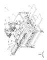
卵容器箱詰システム10は、吸着部16bを有する卵容器移送装置16a(本実施形態では2機であるが、1機でもよく、3機以上でもよい。)と、卵容器12を供給搬送する卵容器搬送コンベア13と、複数の卵容器12を収容するための輸送ケース11を搬送する輸送ケース搬送コンベア(入口コンベア14、出口コンベア15)、輸送ケース搬送コンベア(14,15)から輸送ケース11を受け入れ、かつ卵容器12を収容した後の輸送ケース11を送り出すための搬送装置1を備える。
卵容器移送装置16aは、卵容器搬送コンベア13で搬送されてきた1または1以上の卵容器12を、その上方から吸着部16b(複数の吸着パッド200)で3つの卵容器12のそれぞれの所定位置の蓋12aを吸着し、卵容器12を、搬送装置1の上で待機している輸送ケース11の内部に移送する。また、卵容器箱詰システム10は、搬送装置1及び卵容器移送装置16を支持する架台17を備えている。
(Embodiment 1)
An egg
The egg
The egg
輸送ケース搬送コンベアは、上流から搬送装置1に向けて輸送ケース11を搬送する入口コンベア14と、搬送装置1から下流に向けて輸送ケース11を搬送する出口コンベア15とを備えている。
The transport case transport conveyor includes an
第1方向D1及び第2方向D2は、それぞれ水平方向(横方向)であって、第1方向D1は、第2方向D2と直交する方向である。そして、第3方向D3は、鉛直方向(上下方向)であって、第1方向D1及び第2方向D2とそれぞれ直交する方向である。 The first direction D1 and the second direction D2 are each a horizontal direction (lateral direction), and the first direction D1 is a direction orthogonal to the second direction D2. The third direction D3 is a vertical direction (vertical direction), and is a direction orthogonal to the first direction D1 and the second direction D2, respectively.
搬送装置1は、複数の輸送ケース11を第1方向D1に並列させて停止させる停止部2と、停止部2に対して上流側に配置される第1搬送部3と、停止部2に対して下流側に配置される第2搬送部4とを備えている。本実施形態においては、停止部2は、二つの輸送ケース11を第1方向D1に並列させて停止させる。輸送ケース11が停止部2にある時に、卵容器12の詰め作業が実行される。なお、一つ、三つ以上の輸送ケース11を第1方向D1に並列させて停止させてもよい。
本実施形態において、搬送装置1は、ローラコンベアで構成されているが、これに限定されない。
The transport apparatus 1 includes a stop unit 2 that stops the plurality of
In the present embodiment, the conveyance device 1 is configured by a roller conveyor, but is not limited to this.
卵容器搬送コンベア13は、卵容器12を第1方向D1に搬送するコンベアベルト13aと、卵容器12をコンベアベルト13a上で停止させる停止装置13bとを備えている。卵容器搬送コンベア13は、停止装置13bが必要に応じて卵容器12を停止させることで、卵容器12、12同士の間に間隔を生じさせつつ、卵容器12を第1方向D1に順次搬送する。
卵容器搬送コンベア13は、2つの卵容器を吸引する動作と3つの卵容器を吸引する動作を交互に実行させる場合に、コンベア下流の吸引待機位置において、2つの卵容器と、3つの卵容器とを交互に吸引待機位置へ搬送させることができる。
The egg
When the egg
卵容器12は、例えば、鶏卵が収容された容器である。本実施形態では、複数の吸着部16bの形状、材質、間隔が、外形サイズの異なる複数種類の卵容器(特に天面の凸形状、その凸形状の間隔(ピッチ)が異なる卵容器)に対応している。詳細は後述する。
The
輸送ケース11は、例えば、上方が開放された箱体であり、本実施形態においては、プラスチックや段ボールで形成された箱体としている。そして、物体11は、長手方向と短手方向とを有しており、例えば、平面視(第3方向D3視)で長方形状に形成されている。本実施形態では、外形サイズの異なる複数種類の卵容器(特に天面の凸形状、その凸形状の間隔(ピッチ)が異なる卵容器)に対応した共通の1種類のサイズの輸送ケースであってもよく、卵容器のサイズに合わせたサイズの輸送ケースであってもよい。制御部100は、輸送ケース11のサイズ、卵容器12のサイズ、出荷製品仕様に応じて、輸送ケースに詰める卵容器の配置を決定し、卵容器移送装置16aの動作を制御する。
The
(卵容器移送装置)
卵容器移送装置16は、6自由度を有する二つのロボット16a,16aと、各ロボット16aの先端に配置され、複数の卵容器12を吸着するための吸着部16b,16bとを備えている。そして、吸着部16bが卵容器搬送コンベア13の吸引待機位置にある卵容器12を同時に吸着し、ロボット16aが動作することで、複数の卵容器12は、搬送装置1の停止部2上に停止している輸送ケース11の内部に運搬される。
(Egg container transfer device)
The egg
吸着部16bについて説明する。
本実施形態において、吸着部16bは、10個入り卵容器1つに対し、6つの蛇腹吸着パッド200を備える。図2Aに示す蛇腹吸着パッド200は、4.5段であり、蛇腹筒状部201および先端リップ202の外径(Φ)が20mmであり、蛇腹筒状の長手方向長さ(L)が28mmである。蛇腹吸着パッド200は、硬度40(A/S)のシリコーンゴム製であり、蛇腹筒状201の厚み(T2)が0.6mm〜1mmであり、先端リップ202の厚み(T1)が0.1mm〜0.5mmである。吸着パッド200の上部は、チューブ300で真空ポンプ(不図示)と接続されている。
The
In the present embodiment, the
図2Bで複数の吸着パッド200の間隔について説明する。本実施形態では、卵がMS〜LLサイズの凸蓋の卵容器12を吸着移送する設定とする。MSの卵容器12(MS)の凸蓋の縦の凸状部12aのピッチ(SP1)と横の凸状部12aのピッチ(SP2)と、LLの卵容器の凸蓋の縦の凸状部12aのピッチ(LP1)と横の凸状部12aのピッチ(LP2)とから、卵容器に対応した縦方向の吸着パッドのピッチ(P1)と横方向の吸着パッドのピッチ(P2)を設定する。ここでは、MS卵容器とLL卵容器との凸状部のピッチの平均を吸着パッドのピッチに設定する。
P1=(LP1+SP1)/2
P2=(LP2+SP2)/2
また、図2Bに示すように、長手方向に平行に隣合うMS卵容器の隣り合う凸状部12a同士のピッチ(SP3)と、容器長手方向に平行に隣合うLL卵容器の隣り合う凸状部12a同士のピッチ(LP3)の平均を求め、容器長手方向に平行に隣合う卵容器に対応した吸着パッドのピッチ(P3)を設定する。
P3=(LP3+SP3)/2
The distance between the plurality of
P1 = (LP1 + SP1) / 2
P2 = (LP2 + SP2) / 2
Further, as shown in FIG. 2B, the pitch (SP3) between adjacent
P3 = (LP3 + SP3) / 2
図3A、3Bは、図2Bの吸着パッド200のレイアウト設定において、容器長手方向に平行に3つの卵容器12(MSサイズ)を置いたときに、吸着パッド200で吸着した状態を示す。図3Aで示すように、左右の先端リップ202は、凸状部12aの天面および側面と接触し吸着する。また、図3Bに示すように、左右の卵容器12(MS)において、先端リップ202は、凸状部12aの天面および側面と接触し吸着する。側面との接触箇所を符号202aで示す。このように、吸着パッド200は、平坦面に限らず、曲面、縁などでも好適に接触し吸引可能である。
FIGS. 3A and 3B show a state where suction is performed by the
(卵容器を輸送ケースへ詰める方法)
本実施形態において、卵容器を輸送ケース(例えば段ボール)に詰める方法について説明する。図4A〜4Cは、箱詰した状態を輸送ケースの上から下に見た場合(上段の図)と、輸送ケースの側面からその内部を透かして見た場合(下段の図)の両方を示す。
(How to pack an egg container into a shipping case)
In the present embodiment, a method of packing an egg container in a transport case (for example, cardboard) will be described. FIGS. 4A-4C show both a boxed state viewed from the top of the transport case (top view) and a see through the inside of the transport case from the side (bottom view) .
図4Aは、輸送ケースのx方向(長手方向)、y方向(短手方向)に対し、卵容器の横方向(長手方向)、縦方向(短手方向)を揃えるように2×3(合計6)の配置で詰める。側面でみると、1段目と2段目は同じように積み重ねられる。この場合、卵容器移送装置1は、3つの卵容器を同時に吸引し、輸送ケース11へ詰め、その横に次の3つの卵容器を詰める。卵容器移送装置16は、次の段においても、同様の動作で、卵容器を積んでゆく。吸引制御部(不図示)は、卵容器の吸着、脱着処理の際に、真空ポンプ(不図示)に吸引を制御する。また、主制御部(不図示)は、移送機構である多軸ロボット16aを制御する。
FIG. 4A is 2 × 3 (total) so that the lateral direction (longitudinal direction) and longitudinal direction (shorter direction) of the egg container are aligned with the x direction (longitudinal direction) and y direction (shorter direction) of the transport case. Pack in the arrangement of 6). In terms of sides, the first and second tiers are stacked in the same way. In this case, the egg container transfer device 1 simultaneously sucks three egg containers, packs them into the
図4Bは、輸送ケースのy方向(短手方向)と、卵容器の横方向(長手方向)を合わせて、x方向に向かって卵容器を4つ詰める。輸送ケースには隙間(卵容器より小さいサイズ)が生じている。これは、共通の輸送ケースを使用する場合(輸送ケースと卵容器のサイズが合っていない場合)に起こる。側面でみると、次の段を詰める時には、下位段と上位段とではその隙間の位置を互い違いにして詰める。この場合、卵容器移送装置16は、2つの卵容器を同時に吸引し、輸送ケースのy方向の一方側面へ合わせ、次の2つをその横に並べて詰める。卵容器移送装置16は、次の段では、2つの卵容器を同時に吸引し、輸送ケースのy方向のその他方側面へ合わせ、次の2つをその横に並べて詰める。このようにすることで、輸送ケース内での卵容器の横移動(隙間方向への移動)を抑制して、輸送中の卵割れ等を抑えることができる。
FIG. 4B aligns the y direction (transverse direction) of the transport case with the lateral direction (longitudinal direction) of the egg container to pack four egg containers in the x direction. There is a gap (smaller than the egg container) in the transport case. This occurs when using a common shipping case (if the shipping case and the egg container do not fit). In terms of aspect, when packing the next stage, the positions of the gaps are staggered between the lower stage and the upper stage. In this case, the egg
図4Cは、輸送ケースのy方向(短手方向)と、卵容器の縦方向(短手方向)を合わせて、3つの卵容器を詰め、次いで2つの卵容器を、90度回転した配置として詰める。後で詰めた2つの卵容器の横方向の両サイドに隙間が生じる。これも同様に、共通の輸送ケースを使用してため起こる。側面でみると、次の段を詰める時には、下位段と上位段とでは、3つの容器を詰める位置と2つの容器を詰める位置とを互い違いにしてある。この場合、卵容器移送装置16は、3つの卵容器を同時に吸引し、輸送ケースのx方向の一方側面に3つの卵容器の横方向端面を合わせ、次の2つの卵容器を90度回転させてその横に並べて詰める。卵容器移送装置16は、次の段では、3つの卵容器を同時に吸引し、輸送ケースのx方向のその他方側面に3つの卵容器の横方向端面を合わせ、次の2つの卵容器を90度回転させてその横に並べて詰める。このようにすることで、輸送ケース内での卵容器の横移動(隙間方向への移動)を抑制して、輸送中の卵割れ等を抑えることができる。
3つの卵容器と2つの卵容器とを交互に吸引できるように、吸引のON/OFFが制御される。複数の吸着パッド200はチューブ300で真空ポンプと接続され、吸着パッド200のそれぞれにおいて、吸着、脱着が個別に制御される。
In FIG. 4C, the y direction (short side direction) of the transport case is aligned with the longitudinal direction (short side direction) of the egg container to pack three egg containers, and then the two egg containers are rotated 90 degrees. pack. A gap is created on both sides in the lateral direction of two egg containers packed later. This too happens because of the use of a common shipping case. In terms of side, when the next stage is packed, the lower and upper stages alternate between the three container packing position and the two container packing position. In this case, the egg
Suction ON / OFF is controlled so that three egg containers and two egg containers can be alternately suctioned. The plurality of
本実施形態において、多軸ロボットで構成された卵容器移送装置16の主制御部が、卵容器12の吸引位置と輸送ケース11の脱着位置との間において、吸着部16bを最小移動量(あるいは最適移動量)で動かすように制御することで、吸引位置への移動、卵容器吸引、卵容器移送、輸送ケース詰めのトータルの作業時間を短くできる。
In the present embodiment, the main control unit of the egg
(別実施形態)
本実施形態では、多軸ロボットを使用したが、これに限定されず、移送装置として、垂直・水平・回転移動が可能な装置に吸着部(吸着パッド200)を装着してあってもよい。
(Another embodiment)
Although the multi-axis robot is used in the present embodiment, the invention is not limited thereto. The suction unit (suction pad 200) may be attached to a device capable of vertical, horizontal, and rotational movement as a transfer device.
(実施例)
上記卵容器移送装置において、以下の条件で卵容器の移送を行った。
真空ポンプとしてドライポンプ(オリオン社製 KRF25A−V−01B)を使用。
吸着パッドとして、硬度は、40度(A40/S)のシリコーンゴム製を使用。
吸着パッドは、4.5段の蛇腹形パッドを使用。
吸着パッドの蛇腹の筒状の外径およびパッド径(先端のリップ部)は20mm。
筒状の長手方向は、28mm。
吸着パッドの数は、図2Bに示すように、10個入り卵容器(長手方向を横としてみた時に縦2×横5)に対し6とした。
以上の設定で、6種類のサイズ違いの卵容器の全てを吸引、移送できたことを確認した。また、その時の真空ポンプ圧力は、以下の通りであった。
フラットパック:−66.3kPa
MSパック:−65.6kPa
Mパック:−65.3kPa
Lパック:−64.8kPa
LLパック:−64.3kPa
MIXパック:−64.7kPa
上記理論リフト力W(=P×S×n×0.1)からポンプ圧力を求め、安全率を5とした値(58.5kPa)と略一致する結果となった。
(Example)
In the above-mentioned egg container transfer device, transfer of the egg container was performed under the following conditions.
As a vacuum pump, a dry pump (manufactured by Orion KRF25A-V-01B) is used.
As the suction pad, the hardness is made of silicone rubber of 40 degrees (A40 / S).
The suction pad uses a 4.5-step bellows pad.
The outer diameter of the bellows of the suction pad and the diameter of the pad (the tip lip) are 20 mm.
The cylindrical longitudinal direction is 28 mm.
As shown in FIG. 2B, the number of suction pads is 6 for a 10-piece egg container (2 × 5 when viewed in the longitudinal direction).
With the above settings, it was confirmed that all of the six different sized egg containers could be aspirated and transferred. Moreover, the vacuum pump pressure at that time was as follows.
Flat pack: -66.3 kPa
MS pack: -65.6kPa
M pack: -65.3kPa
L pack: -64.8 kPa
LL pack: -64.3kPa
MIX pack: -64.7 kPa
The pump pressure was determined from the theoretical lift force W (= P × S × n × 0.1), and the result was substantially identical to the value (58.5 kPa) where the safety factor was 5.
12 卵容器
200 吸着パッド
201 蛇腹筒状部
202 先端リップ
12
Claims (4)
前記吸着部に接続される吸引手段と、
前記吸着部が取り付けられる移送機構と、
前記卵容器と前記吸着部で吸着処理する場合に、前記吸引手段を制御する吸引制御部と、
前記移送機構の動きを制御する主制御部と、を備え、
前記吸着パッドは、
筒内部がエア吸引のために貫通した蛇腹筒状であり、および、
蛇腹筒状の長手方向長さより、蛇腹筒状または先端リップの外径が小さく、
複数サイズの卵容器の内、卵容器が卵形状に沿った凹凸を形成する凸状部を有する凸蓋を備えており、最小サイズの卵容器の凸蓋の縦の凸状部のピッチ(SP1)と横の凸状部のピッチ(SP2)と、最大サイズの卵容器の凸蓋の縦の凸状部のピッチ(LP1)と横の凸状部のピッチ(LP2)に基づいて、卵容器に対応した縦方向の吸着パッドのピッチ(P1)と横方向の吸着パッドのピッチ(P2)とが設定されている、
卵容器移送装置。 An adsorption unit having at least two adsorption pads for one egg container;
Suction means connected to the suction unit;
A transfer mechanism to which the suction unit is attached;
A suction control unit that controls the suction unit when suction processing is performed by the egg container and the suction unit;
A main control unit that controls the movement of the transfer mechanism;
The suction pad is
The inside of the tube is a bellows-like cylinder which is penetrated for air suction, and
From the bellows cylindrical longitudinal length, the outer diameter of the bellows cylindrical or tip lip rather small,
Among the plurality of sizes of egg containers, the egg container is provided with a convex lid having a convex portion that forms unevenness along the egg shape, and the pitch (SP1) of the vertical convex portions of the convex lid of the minimum sized egg container Egg container based on the pitch (SP2) of the horizontal convex portion and the pitch (LP1) of the vertical convex portion of the convex lid of the largest size egg container and the pitch of the horizontal convex portion (LP2) The pitch (P1) of the vertical suction pad and the pitch (P2) of the horizontal suction pad corresponding to
Egg container transfer device.
卵容器を搬送する卵容器搬送コンベアと、
複数の卵容器を収容するための輸送ケースを搬送する輸送ケース搬送コンベアと、を備え、
前記卵容器移送装置は、
前記卵容器搬送コンベアで搬送されてきた1または1以上の卵容器を、その上方から前記卵容器移送装置の吸着部で卵容器の蓋を吸着し、当該卵容器を前記輸送ケースの内部に移送する、を備える卵容器箱詰システム。 An egg container transfer device according to any one of claims 1 to 3 ;
An egg container transport conveyor for transporting the egg containers;
A transport case transport conveyor for transporting a transport case for accommodating a plurality of egg containers;
The egg container transfer device is
The lid of the egg container is adsorbed by the adsorption section of the egg container transfer device from the upper side of the one or more egg containers transported by the egg container transport conveyor, and the egg container is transported to the inside of the transport case An egg container packaging system comprising:
Priority Applications (1)
| Application Number | Priority Date | Filing Date | Title |
|---|---|---|---|
| JP2017081275A JP6502415B2 (en) | 2017-04-17 | 2017-04-17 | Egg container transfer device |
Applications Claiming Priority (1)
| Application Number | Priority Date | Filing Date | Title |
|---|---|---|---|
| JP2017081275A JP6502415B2 (en) | 2017-04-17 | 2017-04-17 | Egg container transfer device |
Publications (3)
| Publication Number | Publication Date |
|---|---|
| JP2018177325A JP2018177325A (en) | 2018-11-15 |
| JP2018177325A5 JP2018177325A5 (en) | 2019-01-31 |
| JP6502415B2 true JP6502415B2 (en) | 2019-04-17 |
Family
ID=64282386
Family Applications (1)
| Application Number | Title | Priority Date | Filing Date |
|---|---|---|---|
| JP2017081275A Active JP6502415B2 (en) | 2017-04-17 | 2017-04-17 | Egg container transfer device |
Country Status (1)
| Country | Link |
|---|---|
| JP (1) | JP6502415B2 (en) |
Cited By (1)
| Publication number | Priority date | Publication date | Assignee | Title |
|---|---|---|---|---|
| CN109911282A (en) * | 2019-01-22 | 2019-06-21 | 孝感英华机械模具设计有限公司 | A kind of eggs products automatic packaging device |
Families Citing this family (7)
| Publication number | Priority date | Publication date | Assignee | Title |
|---|---|---|---|---|
| JP2018193071A (en) * | 2017-05-12 | 2018-12-06 | 株式会社ナベル | Egg pack transfer device |
| JP2019172288A (en) * | 2018-03-28 | 2019-10-10 | 株式会社ナベル | Egg pack transfer device |
| CN109335075B (en) * | 2018-11-22 | 2024-03-22 | 安徽田园居电子商务股份有限公司 | Egg packaging machine for postal delivery |
| JP7127830B2 (en) * | 2018-12-10 | 2022-08-30 | 共和機械株式会社 | Palletizer hand, palletizer system, and depalletizing/palletizing method |
| CN109969452A (en) * | 2019-04-17 | 2019-07-05 | 河南洁宝节能科技有限公司 | A kind of spiced egg stacking device |
| JP6876343B1 (en) * | 2019-12-26 | 2021-05-26 | 株式会社ナベル | Mobile rack system for egg packs, how to produce egg packs |
| WO2022059574A1 (en) * | 2020-09-18 | 2022-03-24 | 株式会社ナベル | Device for detecting abnormalities when transferring egg pack |
Family Cites Families (5)
| Publication number | Priority date | Publication date | Assignee | Title |
|---|---|---|---|---|
| NL1025964C2 (en) * | 2004-04-16 | 2005-10-18 | Ball & Ball | Device for placing boxes in an outer package. |
| JP2007167973A (en) * | 2005-12-19 | 2007-07-05 | Yokohama Rubber Co Ltd:The | Suction pad using thermoplastic elastomer |
| JP5167508B2 (en) * | 2010-04-22 | 2013-03-21 | 株式会社ナベル | Egg packaging apparatus and egg packaging method |
| JP2014024138A (en) * | 2012-07-25 | 2014-02-06 | Naberu:Kk | Sucking disk, and transfer device provided with the same |
| JP5802932B1 (en) * | 2014-03-31 | 2015-11-04 | 株式会社ナベル | Container filling method |
-
2017
- 2017-04-17 JP JP2017081275A patent/JP6502415B2/en active Active
Cited By (1)
| Publication number | Priority date | Publication date | Assignee | Title |
|---|---|---|---|---|
| CN109911282A (en) * | 2019-01-22 | 2019-06-21 | 孝感英华机械模具设计有限公司 | A kind of eggs products automatic packaging device |
Also Published As
| Publication number | Publication date |
|---|---|
| JP2018177325A (en) | 2018-11-15 |
Similar Documents
| Publication | Publication Date | Title |
|---|---|---|
| JP6502415B2 (en) | Egg container transfer device | |
| US20190351563A1 (en) | Holding device for food | |
| KR102137192B1 (en) | Food input device | |
| JP6921673B2 (en) | Pickup method and pickup device | |
| WO2016185862A1 (en) | Box packing device | |
| WO2015129388A1 (en) | Boxing system | |
| KR20190013984A (en) | Food input device | |
| JP2013249175A (en) | Package supplying device | |
| CN111942653B (en) | Adsorption carrying device | |
| JP6371494B2 (en) | Goods transshipment device | |
| JP3684278B2 (en) | Adsorbent for suspending articles and boxing device using the same | |
| JP6379012B2 (en) | Goods transfer device | |
| ES2778600T3 (en) | Systems and methods of mechanical conveyor and food packaging | |
| JP6116879B2 (en) | Adsorption conveyance device and adsorption conveyance method | |
| JP5311458B2 (en) | Container group loading device and loading method | |
| JP6001965B2 (en) | Package supply device | |
| JP6173028B2 (en) | Cardboard supply and discharge device for boxing | |
| JP2015160299A (en) | Adsorption device | |
| JP5307455B2 (en) | Holding and conveying device | |
| JP3913400B2 (en) | Adsorption device for taking out goods | |
| JP6348322B2 (en) | Accumulation device and boxing device | |
| JP4326233B2 (en) | Adsorption device for plastic sheet packing products | |
| EP2780238B1 (en) | A packaging assembly | |
| JP2011225262A (en) | Apparatus and method for egg packaging | |
| JP6984859B2 (en) | Transshipment equipment |
Legal Events
| Date | Code | Title | Description |
|---|---|---|---|
| A521 | Written amendment |
Free format text: JAPANESE INTERMEDIATE CODE: A523 Effective date: 20181214 |
|
| A621 | Written request for application examination |
Free format text: JAPANESE INTERMEDIATE CODE: A621 Effective date: 20181214 |
|
| A871 | Explanation of circumstances concerning accelerated examination |
Free format text: JAPANESE INTERMEDIATE CODE: A871 Effective date: 20181214 |
|
| A975 | Report on accelerated examination |
Free format text: JAPANESE INTERMEDIATE CODE: A971005 Effective date: 20181220 |
|
| A131 | Notification of reasons for refusal |
Free format text: JAPANESE INTERMEDIATE CODE: A131 Effective date: 20190124 |
|
| A521 | Written amendment |
Free format text: JAPANESE INTERMEDIATE CODE: A523 Effective date: 20190218 |
|
| TRDD | Decision of grant or rejection written | ||
| A01 | Written decision to grant a patent or to grant a registration (utility model) |
Free format text: JAPANESE INTERMEDIATE CODE: A01 Effective date: 20190312 |
|
| A61 | First payment of annual fees (during grant procedure) |
Free format text: JAPANESE INTERMEDIATE CODE: A61 Effective date: 20190320 |
|
| R150 | Certificate of patent or registration of utility model |
Ref document number: 6502415 Country of ref document: JP Free format text: JAPANESE INTERMEDIATE CODE: R150 |
|
| R250 | Receipt of annual fees |
Free format text: JAPANESE INTERMEDIATE CODE: R250 |