JP6501552B2 - How to give robustness to piping structures, aircraft, and leak detection - Google Patents
How to give robustness to piping structures, aircraft, and leak detection Download PDFInfo
- Publication number
- JP6501552B2 JP6501552B2 JP2015029569A JP2015029569A JP6501552B2 JP 6501552 B2 JP6501552 B2 JP 6501552B2 JP 2015029569 A JP2015029569 A JP 2015029569A JP 2015029569 A JP2015029569 A JP 2015029569A JP 6501552 B2 JP6501552 B2 JP 6501552B2
- Authority
- JP
- Japan
- Prior art keywords
- cover
- vent
- leak
- temperature
- gas
- Prior art date
- Legal status (The legal status is an assumption and is not a legal conclusion. Google has not performed a legal analysis and makes no representation as to the accuracy of the status listed.)
- Expired - Fee Related
Links
- 238000001514 detection method Methods 0.000 title claims description 20
- 230000008878 coupling Effects 0.000 claims description 19
- 238000010168 coupling process Methods 0.000 claims description 19
- 238000005859 coupling reaction Methods 0.000 claims description 19
- 238000000034 method Methods 0.000 claims description 6
- 230000000740 bleeding effect Effects 0.000 claims 1
- 239000012530 fluid Substances 0.000 claims 1
- 239000011810 insulating material Substances 0.000 description 6
- 230000004048 modification Effects 0.000 description 4
- 238000012986 modification Methods 0.000 description 4
- 230000002093 peripheral effect Effects 0.000 description 4
- 230000035945 sensitivity Effects 0.000 description 4
- 238000000605 extraction Methods 0.000 description 3
- 239000007787 solid Substances 0.000 description 3
- 238000009423 ventilation Methods 0.000 description 3
- 230000009471 action Effects 0.000 description 2
- 238000009434 installation Methods 0.000 description 2
- 230000000149 penetrating effect Effects 0.000 description 2
- 239000013585 weight reducing agent Substances 0.000 description 2
- JOYRKODLDBILNP-UHFFFAOYSA-N Ethyl urethane Chemical compound CCOC(N)=O JOYRKODLDBILNP-UHFFFAOYSA-N 0.000 description 1
- 230000000903 blocking effect Effects 0.000 description 1
- 230000008859 change Effects 0.000 description 1
- 239000012141 concentrate Substances 0.000 description 1
- 238000005260 corrosion Methods 0.000 description 1
- 230000007797 corrosion Effects 0.000 description 1
- 230000002708 enhancing effect Effects 0.000 description 1
- 239000004744 fabric Substances 0.000 description 1
- 239000000835 fiber Substances 0.000 description 1
- 239000006260 foam Substances 0.000 description 1
- 239000011491 glass wool Substances 0.000 description 1
- 239000012774 insulation material Substances 0.000 description 1
- 239000007769 metal material Substances 0.000 description 1
- 238000012856 packing Methods 0.000 description 1
- 230000001105 regulatory effect Effects 0.000 description 1
- 239000011347 resin Substances 0.000 description 1
- 229920005989 resin Polymers 0.000 description 1
- 239000003566 sealing material Substances 0.000 description 1
- 229910001220 stainless steel Inorganic materials 0.000 description 1
- 239000010935 stainless steel Substances 0.000 description 1
Images


Classifications
-
- F—MECHANICAL ENGINEERING; LIGHTING; HEATING; WEAPONS; BLASTING
- F16—ENGINEERING ELEMENTS AND UNITS; GENERAL MEASURES FOR PRODUCING AND MAINTAINING EFFECTIVE FUNCTIONING OF MACHINES OR INSTALLATIONS; THERMAL INSULATION IN GENERAL
- F16L—PIPES; JOINTS OR FITTINGS FOR PIPES; SUPPORTS FOR PIPES, CABLES OR PROTECTIVE TUBING; MEANS FOR THERMAL INSULATION IN GENERAL
- F16L55/00—Devices or appurtenances for use in, or in connection with, pipes or pipe systems
- F16L55/16—Devices for covering leaks in pipes or hoses, e.g. hose-menders
- F16L55/168—Devices for covering leaks in pipes or hoses, e.g. hose-menders from outside the pipe
-
- F—MECHANICAL ENGINEERING; LIGHTING; HEATING; WEAPONS; BLASTING
- F16—ENGINEERING ELEMENTS AND UNITS; GENERAL MEASURES FOR PRODUCING AND MAINTAINING EFFECTIVE FUNCTIONING OF MACHINES OR INSTALLATIONS; THERMAL INSULATION IN GENERAL
- F16L—PIPES; JOINTS OR FITTINGS FOR PIPES; SUPPORTS FOR PIPES, CABLES OR PROTECTIVE TUBING; MEANS FOR THERMAL INSULATION IN GENERAL
- F16L23/00—Flanged joints
- F16L23/04—Flanged joints the flanges being connected by members tensioned in the radial plane
-
- F—MECHANICAL ENGINEERING; LIGHTING; HEATING; WEAPONS; BLASTING
- F16—ENGINEERING ELEMENTS AND UNITS; GENERAL MEASURES FOR PRODUCING AND MAINTAINING EFFECTIVE FUNCTIONING OF MACHINES OR INSTALLATIONS; THERMAL INSULATION IN GENERAL
- F16L—PIPES; JOINTS OR FITTINGS FOR PIPES; SUPPORTS FOR PIPES, CABLES OR PROTECTIVE TUBING; MEANS FOR THERMAL INSULATION IN GENERAL
- F16L55/00—Devices or appurtenances for use in, or in connection with, pipes or pipe systems
- F16L55/07—Arrangement or mounting of devices, e.g. valves, for venting or aerating or draining
-
- F—MECHANICAL ENGINEERING; LIGHTING; HEATING; WEAPONS; BLASTING
- F17—STORING OR DISTRIBUTING GASES OR LIQUIDS
- F17D—PIPE-LINE SYSTEMS; PIPE-LINES
- F17D5/00—Protection or supervision of installations
- F17D5/02—Preventing, monitoring, or locating loss
- F17D5/06—Preventing, monitoring, or locating loss using electric or acoustic means
-
- G—PHYSICS
- G01—MEASURING; TESTING
- G01M—TESTING STATIC OR DYNAMIC BALANCE OF MACHINES OR STRUCTURES; TESTING OF STRUCTURES OR APPARATUS, NOT OTHERWISE PROVIDED FOR
- G01M3/00—Investigating fluid-tightness of structures
- G01M3/002—Investigating fluid-tightness of structures by using thermal means
-
- G—PHYSICS
- G01—MEASURING; TESTING
- G01M—TESTING STATIC OR DYNAMIC BALANCE OF MACHINES OR STRUCTURES; TESTING OF STRUCTURES OR APPARATUS, NOT OTHERWISE PROVIDED FOR
- G01M3/00—Investigating fluid-tightness of structures
- G01M3/02—Investigating fluid-tightness of structures by using fluid or vacuum
- G01M3/04—Investigating fluid-tightness of structures by using fluid or vacuum by detecting the presence of fluid at the leakage point
- G01M3/16—Investigating fluid-tightness of structures by using fluid or vacuum by detecting the presence of fluid at the leakage point using electric detection means
- G01M3/18—Investigating fluid-tightness of structures by using fluid or vacuum by detecting the presence of fluid at the leakage point using electric detection means for pipes, cables or tubes; for pipe joints or seals; for valves; for welds; for containers, e.g. radiators
-
- G—PHYSICS
- G01—MEASURING; TESTING
- G01M—TESTING STATIC OR DYNAMIC BALANCE OF MACHINES OR STRUCTURES; TESTING OF STRUCTURES OR APPARATUS, NOT OTHERWISE PROVIDED FOR
- G01M3/00—Investigating fluid-tightness of structures
- G01M3/02—Investigating fluid-tightness of structures by using fluid or vacuum
- G01M3/04—Investigating fluid-tightness of structures by using fluid or vacuum by detecting the presence of fluid at the leakage point
- G01M3/20—Investigating fluid-tightness of structures by using fluid or vacuum by detecting the presence of fluid at the leakage point using special tracer materials, e.g. dye, fluorescent material, radioactive material
- G01M3/22—Investigating fluid-tightness of structures by using fluid or vacuum by detecting the presence of fluid at the leakage point using special tracer materials, e.g. dye, fluorescent material, radioactive material for pipes, cables or tubes; for pipe joints or seals; for valves; for welds; for containers, e.g. radiators
-
- F—MECHANICAL ENGINEERING; LIGHTING; HEATING; WEAPONS; BLASTING
- F16—ENGINEERING ELEMENTS AND UNITS; GENERAL MEASURES FOR PRODUCING AND MAINTAINING EFFECTIVE FUNCTIONING OF MACHINES OR INSTALLATIONS; THERMAL INSULATION IN GENERAL
- F16L—PIPES; JOINTS OR FITTINGS FOR PIPES; SUPPORTS FOR PIPES, CABLES OR PROTECTIVE TUBING; MEANS FOR THERMAL INSULATION IN GENERAL
- F16L2201/00—Special arrangements for pipe couplings
- F16L2201/30—Detecting leaks
Landscapes
- Engineering & Computer Science (AREA)
- General Engineering & Computer Science (AREA)
- Mechanical Engineering (AREA)
- Physics & Mathematics (AREA)
- General Physics & Mathematics (AREA)
- Acoustics & Sound (AREA)
- Examining Or Testing Airtightness (AREA)
- Pipeline Systems (AREA)
Description
本発明は、ダクトからのある程度のリーク(漏れ)が許容される場合に、許容される量を逸脱したリークを検知することにロバスト性を与える方法、および当該方法を実現可能な配管構造、およびその配管構造を備えた航空機に関する。 The present invention provides a method of providing robustness in detecting leaks that deviate from an acceptable amount when a certain amount of leaks from the duct is tolerated, and piping structures that can realize the method, and The present invention relates to an aircraft provided with the piping structure.
航空機の機体には、エンジンからの高温の抽気が流れる配管が設けられている(例えば、特許文献1)。
図12(a)に示すように、抽気配管80は、複数のダクト81と、ダクト81同士を接続するカップリング82とを備えている。カップリング82は、互いに突き当てられたダクト81のフランジ(図示省略)を挟み込んでいる。
航空機の典型的な抽気配管80では、重量低減および整備性などの観点から、フランジ間やカップリング82とフランジとの間にパッキン等の封止材を設けておらず、フランジ間から外部へと少量の抽気がリークするのを許容している。
The fuselage of the aircraft is provided with piping through which high temperature bleed air from the engine flows (for example, Patent Document 1).
As shown to Fig.12 (a), the
From the viewpoint of weight reduction and maintainability, in a typical
少量のリークは許容されるものの、カップリング82が緩んだり破損したりしてダクト81の接続部からのリーク量が増大した場合には、そのことを検知する必要がある。また、ダクト81に亀裂や腐食等が生じてダクト81の本体部からのリークが発生した場合にも、勿論、リークを検知する必要がある。
Although a small amount of leak is acceptable, if the
配管の部位によってはある程度のリークが許容される場合、許容される量のリークを検知することなく、カップリングやダクトの破損等により許容量を逸脱したリークだけを検知したい。
配管から高温の抽気がリークしたことを検知するために、図12(a)に示すように、ダクト81およびカップリング82を覆うカバー83に複数の通気孔84を形成する。そして、通気孔84から流出した抽気により昇温される線状のセンサ85を設ける。昇温すると変化するセンサ85の電気抵抗に基づいて、リークを検知することができる。
When a certain amount of leak is permitted depending on the piping part, it is desirable to detect only a leak that deviates from the allowable amount due to breakage of a coupling or a duct without detecting an allowable amount of leak.
In order to detect that the high temperature bleed air leaks from the piping, as shown in FIG. 12A, a plurality of
ここで、通気孔84から流出した抽気により昇温されるセンサ85の各部位85Aの温度は、通気孔84から部位85Aまでの距離や、周囲の気体の流動や気体の温度・圧力の変動などの種々の要因により大きくバラつく。
通気孔84から流出した抽気の流量(以下、リーク流量)に対して、センサ85の部位85A毎の温度のバラツキが大きいと、相応のリーク流量に対応する温度をリークセンサに設定し、その設定温度以上の温度がセンサ85により感応されたならばリークしたことを検知するにあたり、適切な設定温度を定めることが非常に難しい。設定温度によっては、許容される少量のリークを頻繁に検知したり、許容量を逸脱したリークが検知されずに配管の周囲環境が高温になるといったことが起こりうる。
それを避けるために、リーク検知のロバスト性を具備することが重要である。
Here, the temperature of each
If the temperature variation of each
To avoid that, it is important to have the robustness of the leak detection.
以上より、本発明は、リーク検知にロバスト性を与える方法、当該方法を実現可能な配管構造、およびその配管構造を備えた航空機を提供することを目的とする。 In view of the above, the present invention aims to provide a method for providing robustness to leak detection, a piping structure capable of realizing the method, and an aircraft provided with the piping structure.
配管のカバーに形成されたリーク検知用の複数の通気孔の位置は、カバーの周方向においてバラバラで統一されていない。
本発明の発明者は、通気孔の周方向の位置によっては、小流量のリークが検知されたり検知されなかったりすることに着目した。
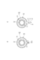
例えば、図12(b)に示すように、通気孔84が上方に位置していると、通気孔84から孔軸方向に沿って上方へと流出するリーク流は、流量が小さい場合でも実線矢印で示すようにそのままセンサ85へと到達する。到達した高温のリーク流によりセンサ85が昇温することで、リークが検知される。
一方、図12(c)に示すように、通気孔84が下方に位置していると、リーク流の流量が小さい場合は、浮力の影響により、破線矢印で示すようにリーク流が周囲の気体に対して浮上する。そのため、センサ85には高温の気体が到達しないので、リークが検知されない。
The positions of the plurality of leak detection vents formed in the pipe cover are not uniformly unified in the circumferential direction of the cover.
The inventor of the present invention has noted that a small flow rate leak may or may not be detected depending on the circumferential position of the vent.
For example, as shown in FIG. 12 (b), when the
On the other hand, as shown in FIG. 12 (c), when the flow rate of the leak flow is small when the
上記の知見に基づいてなされた本発明の配管構造は、略水平方向に沿って配置され、周囲の雰囲気の温度よりも高い温度の気体が連続して流れる複数のダクトおよびダクト同士を接続する複数のカップリングを有する配管と、配管の外周を覆うカバーと、を備えている。
カバーは、配管からリークした気体を当該カバーの外側へと流出させる複数の通気口を配管の長さ方向に間隔をおいて規定している。複数の通気口として、カバーは、複数のカップリング(「接続部」)に対応して配置される複数の第1通気口と、複数のダクトに対応して配置される複数の第2通気口と、を少なくとも有する。すなわち、本発明の配管構造において、接続部には第1通気口、複数のダクトに対応する一般部には第2通気口が存在する。
そして、本発明は、(i)複数の第1通気口の各々の位置は、カバーの横断面において2時位置から6時位置を経て10時位置までの範囲に、実質的に定められていること、および、(ii)複数の第2通気口の各々の位置は、カバーの横断面において12時位置またはその近傍に、実質的に定められていることを特徴とする。
The piping structure of the present invention made based on the above findings is disposed along a substantially horizontal direction, and connects a plurality of ducts and ducts in which gas having a temperature higher than the temperature of the surrounding atmosphere flows continuously. And a cover covering the outer periphery of the pipe.
The cover defines a plurality of vents spaced at intervals along the length of the pipe, which allow the gas leaked from the pipe to flow out of the cover. As the plurality of vents, the cover includes a plurality of first vents disposed corresponding to the plurality of couplings ("connections") and a plurality of second vents disposed corresponding to the plurality of ducts. And at least. That is, in the piping structure of the present invention, the first vent is present at the connection portion, and the second vent is present at the general portion corresponding to the plurality of ducts.
The present invention, each of positions of (i) a plurality of first vent is in the range of the cross-section of the cover from 2 o'clock to 10 o'clock through 6 o'clock position, it is substantially defined And (ii) the position of each of the plurality of second vents is substantially defined at or near the 12 o'clock position in the cross section of the cover .
本発明の配管構造は、気体のリークを検知するリークセンサを具備することができる。リークセンサは、複数の通気口の各々に対応する位置を通り、カバーの外側の気体の温度または濃度に感応する感応部と、感応部の状態を用いて、リークを検知する検知部と、を有するように構成することができる。 The piping structure of the present invention can be equipped with a leak sensor that detects a gas leak. The leak sensor passes a position corresponding to each of the plurality of vents, and includes a sensitive part that senses the temperature or concentration of the gas outside the cover, and a detection part that detects a leak using the state of the sensitive part. It can be configured to have.
本発明の配管構造において、リークセンサは、第1通気口以外の通気口である複数の第2通気口に対応する位置で、カバーの周方向に沿って上方へと立ち上がるように配置されていることが好ましい。 In the piping structure of the present invention, the leak sensor is arranged to rise upward along the circumferential direction of the cover at a position corresponding to a plurality of second vents which are vents other than the first vent. Is preferred.
本発明の配管構造は、第1通気口の近傍に、気体の上昇を規制する屋根を備え、屋根は、第1通気口を規定するカバーに対して間隔をおいて、第1通気口の上方に配置され、感応部は、屋根の下方に配置されていることが好ましい。なお、屋根を備える場合には、第1通気口は、6時位置およびその付近を除いた残りの範囲内に設けられていることが前提となる。 The piping structure of the present invention includes a roof that restricts the rise of gas in the vicinity of the first vent, and the roof is spaced above the cover defining the first vent and above the first vent. Preferably, the sensitive part is disposed below the roof. In addition, when providing a roof, it is premised that the 1st vent is provided in the remaining range except 6 o'clock position and its vicinity.
屋根は、当該屋根とカバーとを繋ぐ支持部によりカバーに支持させることも、感応部を挟持するクリップにより感応部に支持させることもできる。 The roof can be supported by the cover by a support that connects the roof and the cover, or can be supported by the sensitive part by a clip that holds the sensitive part.
本発明の配管構造は、第1通気口または第2通気口の近傍に、当該通気口から流出した気体の流れに影響するカバーの外側の気体の流れを遮蔽する防風壁を備えることが好ましい。 The piping structure of the present invention preferably includes a windproof wall in the vicinity of the first vent or the second vent for shielding the flow of gas outside the cover that affects the flow of gas flowing out of the vent.
本発明の航空機は、上述の配管構造を備えることを特徴とする。
航空機の動力源であるエンジンまたは補助動力装置からの抽気が流れる配管構造に本発明を適用可能である。
An aircraft of the present invention is characterized by comprising the above-described piping structure.
The present invention is applicable to a piping structure through which the bleed air from the engine or auxiliary power unit, which is a power source of an aircraft, flows.
本発明のリーク検知にロバスト性を与える方法は、略水平方向に沿って配置される配管の外周を覆うカバーに、配管の長さ方向に間隔をおいて複数の通気口を規定し、配管からリークした配管の周囲の雰囲気の温度よりも高い温度である気体を通気口からカバーの外側へと流出させ、通気口に対応する位置での気体の温度または濃度を用いて、気体のリークを検知するにあたり、(i)複数の通気口のうち、配管を構成する複数のカップリングに対応する複数の第1通気口の各々の位置を、カバーの横断面において2時位置から6時位置を経て10時位置までの範囲に、実質的に定めておくこと、および、(ii)複数の通気口のうち、配管を構成する複数のダクトに対応して配置される複数の第2通気口の各々の位置を、カバーの横断面において12時位置またはその近傍に、実質的に定めておくことを特徴とする。
According to the method of the present invention for providing robustness to leak detection, a plurality of vents are defined at intervals in the longitudinal direction of the pipe in a cover covering the outer periphery of the pipe disposed substantially in the horizontal direction, The gas whose temperature is higher than the temperature of the atmosphere around the leaked piping is made to flow out of the vent to the outside of the cover, and the temperature or concentration of the gas at the position corresponding to the vent is used to detect the gas leak Upon that, (i) among the plurality of vents, the position of each of the plurality of first vent corresponding to a plurality of couplings constituting the piping, the 6 o'clock position from the 2 o'clock position in the transverse plane of the cover And (ii) a plurality of second vents disposed corresponding to a plurality of ducts constituting the pipe among the plurality of vents. Each position on the cross section of the cover It is characterized in that it is substantially defined at or near the 12 o'clock position .
本発明によれば、略水平に配置される配管を覆うカバーに形成されたリーク検知用の第1通気口の位置がカバーの横断面における下部および下部に近い上記範囲内に位置しているので、配管内からリークし、第1通気口から流出した気体の流量が小さい場合に、気体の流れが浮力によりリークセンサの感応部から逸れて上昇する。第1通気口の位置が上記の範囲内に実質的に統一されていると、浮力による流れの操作によりリーク検知にロバスト性が与えられるので、リークの誤検知を避けながら配管構造の信頼性を確保することができる。
また、第1通気口の近傍に屋根を備えていると、第1通気口から流出した流れが許容されるリーク量よりも増加した際に、屋根の下でリークセンサの感応部に集中することで感応部が急激に反応する。それによってロバスト性を向上させることができる。
According to the present invention, the position of the first vent for leak detection formed in the cover covering the piping disposed substantially horizontally is located in the above-mentioned range close to the lower portion and the lower portion in the cross section of the cover. When the flow rate of the gas leaked from the inside of the pipe and flowed out from the first vent is small, the flow of the gas deviates and rises from the sensitive part of the leak sensor by buoyancy. When the position of the first vent is substantially unified within the above range, the operation of flow by buoyancy gives robustness to leak detection, so reliability of the piping structure is avoided while false detection of leak is avoided. It can be secured.
In addition, if a roof is provided in the vicinity of the first vent, when the flow flowing out from the first vent increases more than the allowable leak amount, it concentrates on the sensitive part of the leak sensor under the roof. The sensitive part reacts sharply. Thereby, the robustness can be improved.
以下、添付図面を参照しながら、本発明の実施形態について説明する。
〔第1実施形態〕
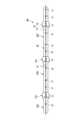
図1および図2に示す配管構造10は、航空機のエンジンからの抽気を空調装置や防氷装置等に供給する。
配管構造10は、航空機の主翼の長さ方向にほぼ沿って延びており、主翼の内部に用意されたスペースに、略水平方向に沿って配置されている。「水平方向」は、地上に駐機された状態の航空機における水平方向に該当する。
配管構造10は、主翼を構成するリブやスパー、ストリンガ等の構造部材により支持されている。
本明細書において、「上」は鉛直方向の上方をいい、「下」は鉛直方向の下方をいうものとする。
Hereinafter, embodiments of the present invention will be described with reference to the accompanying drawings.
First Embodiment
The piping
The piping
The piping
In the present specification, "upper" refers to the upper side in the vertical direction, and "lower" refers to the lower side in the vertical direction.
本実施形態の配管構造10は、胴体の後端に設けられた補助動力装置からの抽気を空調装置や防氷装置等に供給するものにも適合する。その場合も、配管構造10は、機体に用意されたスペースに略水平方向に沿って配置され、機体の構造部材により支持されている。
The piping
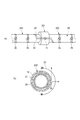
配管構造10は、図2(a)および(b)に示すように、複数のダクト21および複数のカップリング22を有する配管20と、配管20の外周を覆うカバー23および断熱材24と、配管20内からの抽気のリークを検知するリークセンサ30(図1)とを備えている。
配管20は、ステンレス鋼等の金属材料から形成されている。配管20は、カップリング22およびダクト21の端部である接続部201と、ダクト21の一般部202とに区分されている。一般部202は、ダクト21の端部を除いたダクト21の本体部をいう。
The piping
The
複数のダクト21は、内部が互いに連通しており、これらのダクト21の内部をエンジンから取り出された高温の抽気が連続して流れる。ダクト21の各々の外周は、断熱材24(図2(b))により包囲されている。
断熱材24としては、例えば、グラスウール、ウレタンフォーム等、種々のものを用いることができる。
ダクト21の両端には、フランジ21A(図2(b))が形成されている。隣り合うダクト21同士のフランジ21A,21Aは互いに突き当てられる。
カップリング22は、フランジ21A,21Aを挟み込むことでダクト21同士を接続する。
The insides of the plurality of
As the
At both ends of the
The
カバー23は、接続部201の外周を覆う複数の接続部カバー11と、一般部202および断熱材24の外周を覆う複数の一般部カバー12とを備えている。
接続部カバー11は、突き当てられたフランジ21A,21Aに沿って接続部201に装着される。接続部カバー11の内側に断熱材24を配置することもできる。
一般部カバー12および接続部カバー11は、配管20内をある程度は保温し、外力から配管20を保護する。接続部カバー11および一般部カバー12としては、例えば、樹脂の繊維織物から形成されたものを用いることができる。これらのカバー11,12が断面リング状に形成されていると、配管20に装着し易い。
The
The
The
典型的な配管構造であれば、突き当てられたフランジ間や、フランジおよびカップリングの間にシールゴムを介装したり、フランジ同士をボルトで締め付けることなどにより、ダクトの気密が確保されている。
しかし、本実施形態の配管構造10では、航空機の重量低減、整備性などの理由から、接続部201の気密を確保する措置がとられていない。配管構造10では、フランジ21A,21Aの間から配管構造10の外部へと少量の抽気がリークすることが許容されている。
In the case of a typical piping structure, air tightness of the duct is secured by interposing a seal rubber between the butted flanges, between the flange and the coupling, or by fastening the flanges with a bolt.
However, in the
接続部201に小流量のリークは許容されるものの、カップリング22が緩んだりフランジ21Aやカップリング22が破損したことで許容量を逸脱したリークについては検知する必要がある。
また、一般部202においては、リーク量にかかわらず、発生したリークを確実に検知する必要がある。
Although a small flow leak is permitted to the
Further, in the
配管20から高温の抽気がリークしたことを検知するために、図2(a)に示すように、一般部カバー12および接続部カバー11に、リーク検知用の通気孔31,32を形成するとともに、通気孔31,32の近傍にリークセンサ30のセンサ部33を配置し、通気孔31,32に対向する部位33Aが昇温すると変化するセンサ部33の電気抵抗に基づいてリークを検知している。
In order to detect that the high temperature extraction air leaks from the piping 20, as shown in FIG. 2A, the
リークセンサ30(図1)は、接続部201については、許容される量を逸脱したリークだけを検知するとともに、一般部202については、小流量のリークも含めてリーク全般を検知する。リークセンサ30は、各通気孔31,32を経由する線状のセンサ部33の電気抵抗に基づいて、接続部201および一般部202のリークを一括して検知する。リークセンサ30には、リーク検知の閾値としての設定温度が与えられる。
The leak sensor 30 (FIG. 1) detects only leaks that deviate from the allowable amount for the
リークセンサ30(図1)は、温度に感応する温度センサに相当するセンサ部33と、センサ部33の電気抵抗を用いて、検知すべきリークを検知するコントローラ34とを有している。
センサ部33は、冗長性を確保するために2重化されている。
センサ部33の幅(径)は、通気孔31,32の孔径よりも小さく、例えば数mmである。
センサ部33としては、昇温されると電気的特性が変化して電気抵抗が変化するものを適宜に用いることができる。
センサ部33は、長さ方向に適宜な間隔をおいて配置される図示しないブラケットにより、カバー23の外周部との間に少し間隔をあけて支持される。ブラケットは、機体構造や機体に設置された装備品に固定されている。
The leak sensor 30 (FIG. 1) has a
The
The width (diameter) of the
As the
The
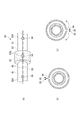
接続部カバー11(図2)には、当該カバー11を厚み方向に貫通する円形の第1通気孔31が形成されている。
第1通気孔31は、接続部カバー11の周上の1箇所に形成されている(図3)。
接続部201の周方向の任意の箇所からリークした抽気は、第1通気孔31から接続部カバー11の外側へと流出する。
In the connection portion cover 11 (FIG. 2), a circular
The first vent holes 31 are formed at one place on the circumference of the connection portion cover 11 (FIG. 3).
The bleed air leaked from an arbitrary location in the circumferential direction of the
一般部カバー12(図2)には、当該カバー12を厚み方向に貫通する円形の第2通気孔32が形成されている。第1通気孔31および第2通気孔32の各々の径は、同じであってもよいし、相違していてもよい。また、第1通気孔31および第2通気孔32の各々の形状は円形に限らず、他の形状であってもよい。
第2通気孔32は、長さ方向に所定の間隔をおいて複数形成されている。第2通気孔32は、第1通気孔31と同様に、一般部カバー12の与えられた位置における周上の1箇所に形成されている。
一般部202の長さ方向の任意の部位でかつ周方向の任意の箇所に生じた亀裂等からリークした抽気は、断熱材24を通過し、亀裂等に近い第2通気孔32から一般部カバー12の外側へと流出する。
In the general part cover 12 (FIG. 2), a circular
A plurality of
Bleed air leaked from a crack or the like generated at any part in the length direction of the
リークセンサ30のセンサ部33は、第1通気孔31の各々の近傍と、第2通気孔32の各々の近傍とを通るように、カバー23に沿って取り回される。
The
配管構造10は、接続部201に関し、外乱に際しても、許容される量のリークを検知せずに、許容量を逸脱したリークだけを検知する第1のロバスト性を具備している。第1のロバスト性は、接続部201にそれぞれ対応する第1通気孔31の位置を、接続部カバー11を上部11Uと下部11Lとに区分したときの下部11Lに一律的に定めることにより与えられている。下部11Lは、接続部カバー11の横断面において、3時位置から6時位置を経て9時位置までの領域に該当し、上部11Uは下部11Lの残りの領域に該当する。第1通気孔31の位置は、第1通気孔31の向き、すなわち、第1通気孔31の孔軸がカバー23の基準位置(例えば図4(b)のA)に対してなす角度(ローテーション)のことを意味しており、本明細書においては、カバー23の横断面を時計の文字盤と見立てたときの時刻に対応している。第2通気孔32の位置についても同様である。 図1〜図3には、下部11Lに位置する第1通気孔31の一例として、接続部カバー11の横断面において3時の位置に規定された第1通気孔31を示している。
The piping
さらに、配管構造10には、一般部202に関し、外乱に際しても、発生したリークを確実に検知する第2のロバスト性をも具備している。第2のロバスト性は、一般部202に対応するの第2通気孔32の位置を、一般部カバー12の横断面において12時位置またはその近傍に一律的に定めることにより与えられている。
Furthermore, the piping
外乱因子としては、センサ部33の周囲の雰囲気(以下、気体)の流動やその気体の温度・圧力の変動、振動や航空機の姿勢によるセンサ部33と通気孔31,32との距離のバラツキ等がある。そういった外乱に対するロバスト性が与えられている配管構造10においては、接続部201および一般部202のそれぞれにおいて狙いとするリークが正しく検知される。
Disturbance factors include the flow of the atmosphere (hereinafter referred to as gas) around the
次に、本実施形態の配管構造10による作用について説明する。
以下では、第1通気孔31あるいは第2通気孔32から流出した抽気の流れのことをリーク流といい、リーク流の流量のことをリーク流量というものとする。
リーク流の温度は、配管構造10の周囲の気体の温度よりも高いので、リーク流と周囲の気体との密度差に基づく浮力がリーク流に働く。リーク流の流量が小さいほど、浮力がリーク流に及ぼす影響が大きい。このことを利用して、第1のロバスト性および第2のロバスト性を実現している。
Next, the operation of the
Hereinafter, the flow of the bleed air flowing out of the
Since the temperature of the leak flow is higher than the temperature of the gas around the piping
まず、接続部201に関する第1のロバスト性について説明する。
図3(a)は、第1通気孔31からのリーク流の流量が小さい場合に対応し、図3(b)は、第1通気孔31からのリーク流の流量が大きい場合に対応する。
上述したように、接続部201に対応する第1通気孔31は、接続部カバー11の下部11Lに位置している。そして、センサ部33は、第1通気孔31の近傍で、かつ、接続部カバー11の外周部から少し離れた位置に配置されている。
リーク流の流量が小さい場合は、図3(a)に破線の矢印F1で示すように、第1通気孔31から孔軸方向に流出したリーク流が、浮力の影響を受けて、周囲の気体に対して接続部カバー11の外周部に沿って上昇する。このリーク流により、破線の矢印F2で示すように周囲の気体がリーク流に向けて連行される。
上記のように、リーク流がセンサ部33から逸れて上昇し、リーク流に伴って周囲の気体がセンサ部33の付近を流動することから、温度Thで高温のリーク流が流出していてもセンサ部33の付近の気体温度Tcの昇温が抑制されている。温度Thは、第1通気孔31から流出する時点のリーク流の温度に相当する。
First, the first robustness of the
FIG. 3A corresponds to the case where the flow rate of the leaked flow from the
As described above, the
When the flow rate of the leak flow is small, as shown by the broken arrow F1 in FIG. 3A, the leak flow flowing out from the
As described above, the leak flow deviates from the
一方、リーク流の流量が大きい場合は、図3(b)に実線の矢印F3で示すように、第1通気孔31から流出したリーク流が浮力に打ち勝ち、センサ部33へと到達する。すると、高温のリーク流によりセンサ部33が昇温する。
On the other hand, when the flow rate of the leak flow is large, the leak flow that has flowed out of the
昇温することでセンサ部33の電気抵抗が変化する。リークセンサ30のコントローラ34(図1)は、センサ部33の電気抵抗に基づいて、センサ部33の温度が設定温度に到達しているか否かを判定し、設定温度に到達していると判定したならばリークを検知する。
By raising the temperature, the electrical resistance of the
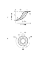
ここで、接続部201の各々を覆う接続部カバー11における第1通気孔31の位置(角度、ローテーション)が下部11Lに統一されていると、いずれの第1通気孔31から流出したリーク流についても、流量が同等であれば浮力による影響が同等となり、センサ部33の各部位33Aの温度も同等となる。第1通気孔31の各々におけるリーク流量とセンサ部温度との関係は、例えば、図4(a)のグラフ中の太い実線101により表される。
太い実線101上においてセンサ部温度が周囲の気体温度Tcと同等に低い領域Aは、浮力が支配的な影響を及ぼすリーク流量の範囲を示している。
一方、太い実線101上においてセンサ部温度がリーク流の温度Thと同様に高い領域Bは、浮力による影響を脱したリーク流量の範囲を示している。
接続部201に関しては、上述したリーク流の向きの相違(F1,F3)の如く、センサ部温度が、リーク流量に応じてリーク流の温度Th側の領域Bと、それよりも温度が低い、接続部カバー11の外側の気体温度Tc側の領域Aとに峻別されている。
Here, when the positions (angles, rotations) of the
The area A where the sensor unit temperature is as low as the surrounding gas temperature Tc on the thick
On the other hand, on the thick
As for the
仮に、第1通気孔31の各々の位置(角度、ローテーション)が統一されていないとすると、例えば、図4(a)に斜線を付した領域102で示すように、リーク流量とセンサ部温度との関係が角度によってバラつく。
Assuming that the positions (angles and rotations) of the first vent holes 31 are not unified, for example, as shown by the hatched
リーク流量とセンサ部温度との関係のバラつきが大きいと、すなわち、あるセンサ部温度に対してリーク流量の幅Wが大きいと、許容リーク流量に対応してリークセンサ30に適切な設定温度を与えることが難しいが、本実施形態では、幅Wが小さくなるため、領域Aに対応する接続部カバー11外側の気体温度Tcと、領域Bに対応するリーク流温度Thとの間の温度をリークセンサ30の設定温度Tsとして容易に定めることができる。
この設定温度Tsを基準として、許容流量のリークを誤検知することなく、許容流量を逸脱したリークだけを検知することができる。
本実施形態によれば、接続部201に関して、許容流量のリークの誤検知を防いで航空機のスムーズな運用に寄与するとともに、許容流量を逸脱したリークを確実に検知して航空機の安全にも寄与することができる。
If the variation in the relationship between the leak flow rate and the sensor unit temperature is large, that is, if the width W of the leak flow rate is large with respect to a certain sensor unit temperature, the
Based on the set temperature Ts, it is possible to detect only the leak that deviates from the allowable flow rate without erroneously detecting the leak of the allowable flow rate.
According to the present embodiment, with regard to the
第1通気孔31が位置する下部11Lの範囲は、拡張することができる。
図4(b)に示すように、2時位置から6時位置を経由して10時位置までの孔位置範囲210に第1通気孔31が位置していれば、流量が小さい場合はリーク流の少なくとも一部がセンサ部33から逸れて上昇し、リーク流に伴って、接続部カバー11外側におけるセンサ部33の周囲の気体の流動も生じる。それによってセンサ部33の周囲の気体温度Tcの昇温が抑制されるので、第1通気孔31の位置として孔位置範囲210が許容される。
なお、3時位置や9時位置に第1通気孔31が位置していると、配管設置スペースの側方に存在するスパーやストリンガ等にセンサ部33を取り付け易い。センサ部33は、図示しないブラケットを用いて、配線方向に沿ったスパーやストリンガ等に取り付けることができる。
The range of the
As shown in FIG. 4B, if the
When the
次に、一般部202に関する第2のロバスト性について説明する。
上述のように、一般部202を覆う一般部カバー12に形成された第2通気孔32(図2(a))の各々は、一般部カバー12の12時位置またはその近傍(一般部カバー12の上部)に位置している。
そうすると、図5に矢印で示すリーク流の流量が大きい場合は勿論のこと、流量が小さい場合であっても、リーク流が上昇してセンサ部33へと到達する。小さい流量のリーク流は、浮力により上方へと誘導されるため、第2通気孔32とセンサ部33とが多少離れていてもセンサ部33に到達する。それによってセンサ部33が昇温すると、リークセンサ30のコントローラ34(図1)は、センサ部33の電気抵抗に基づいて、センサ部33の温度が設定温度に到達しているか否かを判定し、設定温度に到達していると判定したならばリークを検知する。
Next, the second robustness of the
As described above, each of the second vents 32 (FIG. 2A) formed in the
As a result, the leak flow rises and reaches the
一般部202に対応する第2通気孔32の各々の位置が一般部カバー12の上部に統一されていると、いずれの第2通気孔32から流出したリーク流でも、流量の如何によらず、対向するセンサ部33の部位33Aに到達する。
そうすると、第2通気孔32の各々において、設定温度Tsを基準として、リーク流量の如何を問わず、発生したリークを確実に検知するとともに、接続部201に関しては、前述の通り、許容流量を逸脱したリークだけを検知することができる。
When the positions of the
Then, in each of the
本実施形態において、検知対象とするリークの流量とセンサ部温度との関係が若干バラついていたとしても、そのバラツキの度合いは、第1通気孔31の各々の位置および第2通気孔32の各々の位置が統一されていない場合に比べて小さいので、センサ部33の検出感度を通気孔に対応する各位置で揃える調整作業により対処できる。例えば、第1通気孔31および第2通気孔32からの噴流が妥当な位置にまで到達するように各通気孔の孔径を数段階から選定する調整作業が可能である。その他にも、許容される範囲内でカバー23の周方向における第1通気孔31および第2通気孔32の位置を変更したり、センサ部33を取り付けるブラケットの交換によりセンサ部33と通気孔31,32との距離を変えるなどの調整作業が可能である。
In the present embodiment, even if the relationship between the flow rate of the leak to be detected and the temperature of the sensor unit slightly varies, the degree of variation is determined by the position of each of the first vent holes 31 and each of the second vent holes 32. This is smaller than in the case where the positions are not unified, so that the detection sensitivity of the
いずれの第1通気孔31の位置も、極力、所定の孔位置範囲210(図4(b))内に一律的に定められることが好ましいが、センサ部33を取り付けるブラケットと配管20の周囲の部材や機器との干渉や、第1通気孔31から流出する高温のリーク流との接触を避けるべき機器との位置関係、といった事情により、一部の第1通気孔31を孔位置範囲210から外れた位置に形成せざるを得ない場合もある。その場合でも、他の大部分の第1通気孔31の位置が孔位置範囲210内に統一されていれば、第1通気孔31の各々の位置が孔位置範囲210内に実質的に定められているので、本発明に含める。
上記は、第2通気孔32に関しても同様であり、すべての第2通気孔32でなくても、大部分の第2通気孔32の位置が一般部カバー12の12時位置またはその近傍に統一されていれば、第2通気孔32の各々の位置が12時位置またはその近傍に実質的に定められているものとして本発明に含める。
It is preferable that the positions of any of the first vent holes 31 be uniformly determined within the predetermined hole position range 210 (FIG. 4 (b)) as much as possible. Some of the first vent holes 31 are separated from the
The same applies to the second vents 32. Even if all the
〔第1実施形態の変形例〕
図6(a)および(b)に示す第2通気孔35は、第1実施形態の第2通気孔32とは異なり、位置が一般部カバー12の上部には統一されていない。これらの第2通気孔35の各々の位置で、センサ部33が一般部カバー12の周方向に沿って上方へと立ち上がっている。センサ部33は、第2通気孔35の各々の位置でダクト21の軸線に対してほぼ直交している。第2通気孔35は、孔位置範囲210から6時位置およびその近傍を除いた残りの範囲内の適宜な位置に設けることができる。図6(a)および(b)には、第2通気孔35の一例として、3時位置に規定された第2通気孔35を示している。
一般部カバー12の長手方向に第2通気孔35が並んでいる箇所では、センサ部33を一般部カバー12の周りに螺旋状に配置することができる。
Modification of First Embodiment
Unlike the second vent holes 32 of the first embodiment, the second vent holes 35 shown in FIGS. 6A and 6B are not unified at the top of the
Where the
センサ部33が第2通気孔35の位置で上方に立ち上がっていると、図6(b)に破線の矢印で示す流量が小さいリーク流が浮力により上昇し、センサ部33を昇温させる。
図6(b)に実線の矢印で示す流量が大きいリーク流は、浮力に打ち勝ち、第2通気孔35の孔軸方向にそのまま進んでセンサ部33を昇温させる。
つまり、第2通気孔32の位置を上部に統一した第1実施形態と同様に、流量が小さいリーク流をも逃さずにセンサ部33により捕捉することができるので、流量の如何によらず、発生したリークを確実に検知することができる。
When the
The leak flow having a large flow rate indicated by the solid line arrow in FIG. 6B overcomes the buoyancy and advances in the axial direction of the
That is, similar to the first embodiment in which the positions of the
〔第2実施形態〕
次に、図7を参照し、本発明の第2実施形態について説明する。
以下では、第1実施形態と相違する点を中心に説明する。第1実施形態と同様の構成には同じ符号を付している。
第2実施形態の配管構造40では、配管20の接続部201および一般部202の双方において少量のリークが許容される。
Second Embodiment
Next, a second embodiment of the present invention will be described with reference to FIG.
In the following, points different from the first embodiment will be mainly described. The same components as those of the first embodiment are denoted by the same reference numerals.
In the
接続部カバー11および一般部カバー12のいずれにも、厚み方向に貫通する第1通気孔31が形成されている。
接続部カバー11には、第1通気孔31が1つずつ形成されている。
一般部カバー12には、所定の間隔をおいて複数の第1通気孔31が形成されている。
一般部カバー12および接続部カバー11に形成された複数の第1通気孔31は、いずれも2時から6時を経由して10時までの孔位置範囲210内(図4(b))に位置している。
図7には、孔位置範囲210内に位置する第1通気孔31の一例として、カバー23の横断面において3時の位置に規定された第1通気孔31を示している。
センサ部33は、それらの第1通気孔31を順次経由するようにカバー23の長手方向に沿って延びている。
In each of the
One
A plurality of first vent holes 31 are formed in the
The plurality of first ventilation holes 31 formed in the
In FIG. 7, as an example of the
The
第1通気孔31の位置が下方に統一されていることによる作用は、第1実施形態と同様である。簡単に説明する。
一般部202あるいは接続部201において抽気のリークが発生すると、第1通気孔31から孔軸方向に沿って流出したリーク流が、浮力に対して流量が小さい場合に、図3(a)に示すように、センサ部33から逸れて上昇し、それに伴ってセンサ部33の周囲の気体が流動する。そのため、センサ部33の温度が周囲の気体温度Tcと同等に維持される。
一方、あるリーク量を超えて浮力による影響を脱した場合は、図3(b)に示すように、第1通気孔31に対向するセンサ部33にリーク流が到達するので、センサ部33の温度がリーク流の温度Thと同等の温度にまで昇温される。
図3(a)と図3(b)に示すリーク流の向きが相違するように(F1,F3)、リーク流量に応じてセンサ部温度が気体温度Tc側とリーク流の温度Th側とに律せられる(図4(a)参照)。
したがって、気体温度Tcとリーク流温度Thとの間に設定する設定温度Tsを基準として、小流量のリークは許容するが流量が増えるとリークを確実に検知するロバスト性を備えることができる。
The action by the position of the
As shown in FIG. 3A, when the leak of the bleed air occurs in the
On the other hand, when the influence of buoyancy is removed beyond a certain amount of leak, as shown in FIG. 3B, the leak flow reaches the
As the directions of leak flow shown in FIG. 3 (a) and FIG. 3 (b) are different (F1, F3), the sensor temperature is on the gas temperature Tc side and the leak flow temperature Th side according to the leak flow rate. (See Fig. 4 (a)).
Therefore, based on the set temperature Ts set between the gas temperature Tc and the leak flow temperature Th, small flow leakage can be tolerated, but robustness can be provided to reliably detect leak when the flow increases.
一般部202において許容されるリーク流量と、接続部201において許容されるリーク流量とが相違する場合は、第1通気孔31の孔径について一般部カバー12と接続部カバー11とで異ならせることにより、一般部202および接続部201のそれぞれにおいて所望流量のリークを検知することができる。
When the leak flow rate permitted in the
〔第3実施形態〕
次に、図8および図9を参照し、本発明の第3実施形態について説明する。
第3実施形態と、続く第4実施形態で示す配管構造は、許容される量を逸脱したリークだけを検知することに関する第1のロバスト性をより高めるための構成を備えている。
Third Embodiment
Next, a third embodiment of the present invention will be described with reference to FIGS. 8 and 9.
The piping structure shown in the third embodiment and the subsequent fourth embodiment has a configuration for further enhancing the first robustness regarding detecting only leaks that deviate from the allowable amount.
第3実施形態の配管構造は、図8(a)〜(c)に示すように、第1通気孔31の近傍に、屋根13を備えている。屋根13は、孔位置範囲210(図4(b))から6時位置およびその付近を除いた残りの範囲内に位置する第1通気孔31の近傍に配置することができる。屋根13は、第1実施形態で示した第1通気孔31、および第2実施形態で示した第1通気孔31のいずれにも適用することができる。
The piping structure of 3rd Embodiment is equipped with the
板状に形成された屋根13は、第1通気孔31を規定するカバー23に対して間隔をおき、第1通気孔31よりも上方で水平に配置されている。屋根13は、気体の上昇を規制し、屋根13の下方に気体を留める。この屋根13の下方に、センサ部33が配置されている。
The
屋根13は、カバー23側に位置する屋根13の端縁部からカバー23の外周部に向けて延びる一対の支持部14(図8(b))を有しており、それらの支持部14によりカバー23に支持されている。支持部14はカバー23の外周部に取り付けられている。
屋根13とカバー23との間が支持部14により区画されることで、矩形状の開口15(図8(b))が形成されている。
支持部14は屋根13と一体でも別体でもよい。本実施形態では、切欠(開口15)を板に形成することで屋根13と支持部14とを一体に形成している。
The
By dividing the space between the
The
屋根13があることによる作用を説明する。
図9(a)は、第1通気孔31からのリーク流の流量が小さい場合に対応し、図9(b)は、第1通気孔31からのリーク流の流量が大きい場合に対応する。
リーク流の流量が小さい場合は、図9(a)に破線の矢印F1で示すように、第1通気孔31から孔軸方向に流出したリーク流が浮力の影響を受ける。リーク流は、屋根13とカバー23との間の開口15(図8(b))を通り上昇するためセンサ部33には到達せず、さらに、リーク流に伴い、破線の矢印F2で示すように屋根13の下方の気体が開口15からリーク流に向けて吸い出される。 上記のように、リーク流がセンサ部33には到達せず、センサ部33の周囲の気体が流動することにより、センサ部33の周りの温度が維持される。
The action by the presence of the
FIG. 9A corresponds to the case where the flow rate of the leak flow from the
When the flow rate of the leak flow is small, as shown by the broken arrow F1 in FIG. 9A, the leak flow flowing out from the
一方、あるリーク流量を超えると、図9(b)に実線の矢印F3で示すように、第1通気孔31から流出したリーク流が浮力に打ち勝ち、開口15を通り抜けずに屋根13の下方へと吹き込む。吹き込んだリーク流の上昇が屋根13により規制されるため、センサ部33が高温の空気に包まれる。これによってセンサ部33は急激に昇温する。センサ部33の周囲に高温の空気を十分に留めるために、屋根13の寸法L(図8(c))を第1通気孔31の孔径よりも大きく設定するとよい。
On the other hand, when a certain leak flow rate is exceeded, the leak flow that has flowed out of the
上述のように、リーク流の流量が小さいときにはセンサ部33の周囲を低温の気体が流れ、リーク流の流量が大きいときにはセンサ部33の周囲に高温のリーク流が集まる。このように流れの状態が急に切り替わることで、図9(c)に実線で示すように、ある流量を境にセンサ部温度が立ち上がる急峻な流量−温度特性を得ることができる。二点鎖線は、第1実施形態における流量−温度特性の例を示している。
急峻な流量−温度特性によりセンサ部温度がほぼ二値化されていると、大きな外乱時にも、設定温度Tsを基準として、逸脱した流量のリークだけを間違いなく検知することができる。
As described above, a low temperature gas flows around the
If the sensor part temperature is substantially binarized by the steep flow rate-temperature characteristic, even in the case of a large disturbance, only the leak of the deviating flow rate can be detected with reference to the set temperature Ts.
支持部14の形態は特に限定されず、浮力によりリーク流が通り抜ける屋根13とカバー23との間を塞がずに屋根13とカバー23とを繋ぐものであれば任意の形態を採用することができる。
The form of the
屋根13に代えて、図9(d)に示す屋根13´を好ましく採用することができる。
屋根13´は、上述の屋根13に相当する水平部13Aと、水平部13Aの先端から下方へと延びた垂下部13Bとを有している。水平部13Aの下方へと吹き込んだリーク流が垂下部13Bによりその場に留まり、センサ部33の昇温が促進されるため、より急峻な流量−温度特性を得ることができる。したがって、ロバスト性をより向上させることができる。
Instead of the
The roof 13 'has a
〔第4実施形態〕
次に、図10を参照し、本発明の第4実施形態について説明する。
第4実施形態では、屋根13がセンサ部33により支持されている。この点を除いて、第4実施形態は、基本的な構成や作用が第3実施形態と同様である。
Fourth Embodiment
Next, a fourth embodiment of the present invention will be described with reference to FIG.
In the fourth embodiment, the
図10(a)に示すように、屋根13は、センサ部33を挟持するクリップ16に一体化されている。
クリップ16は、カバー23との間に間隔をおいて配置される矩形状の屋根13(図10(b))と、屋根13を下側から支持する挟持部17とを有している。挟持部17は、配管20の長さ方向における屋根13の両端にそれぞれ設けられている。
挟持部17は、図10(c)に示すように、二重化されているセンサ部33,33の両方を挟み込んで保持する。挟持部17はセンサ部33に対して着脱可能である。
このクリップ16を介して屋根13はセンサ部33に支持されている。屋根13とセンサ部33とは一体に形成することもできる。
As shown to Fig.10 (a), the
The
The sandwiching
The
本実施形態によれば、クリップ16をセンサ部33に装着するだけで、屋根13を容易にセンサ部33に支持させることができる。センサ部33の感度を調整するために屋根13のサイズが異なるクリップ16への付け替えも容易である。
センサ部33がカバー23よりも剛性が高い場合には、屋根13を安定して支持するためにも、本実施形態のようにセンサ部33に屋根13を取り付けることが好ましい。
According to the present embodiment, the
When the
〔第5実施形態〕
次に、図11を参照し、本発明の第5実施形態について説明する。
第5実施形態に係る配管構造は、周囲の風F4によるロバスト性の低下を避けるため、防風壁18を備えている。
風F4は、例えば、配管設置スペースの換気や、当該スペース内の温度勾配や圧力勾配などによる気体の流動であり、リーク流の当初の向きを規定する第1通気孔31の孔軸方向に対して交差する向きに流れている。
Fifth Embodiment
Next, a fifth embodiment of the present invention will be described with reference to FIG.
The piping structure according to the fifth embodiment is provided with a
The wind F4 is, for example, gas flow due to ventilation of the piping installation space, temperature gradient or pressure gradient in the space, etc., relative to the axial direction of the
防風壁18は、少なくとも、第1通気孔31が位置するカバー23の表面からセンサ部33まで延在し、風F4を遮蔽することで、リーク流が風F4の向きに従って流されてしまうことを抑制する。
防風壁18は、カバー23の表面に接触するか近づけて配置されており、防風壁18にはセンサ部33が通される切欠180が形成されている(図11(b))。防風壁18は第1通気孔31よりも下方の位置にまで延在している。
The
The
本実施形態の防風壁18は、第4実施形態のクリップ16(図10)および屋根13と一体化されている。センサ部33にクリップ16を装着すると、挟持部17と向きが一致する切欠180の内側にセンサ部33が配置される。
なお、防風壁18は、クリップ16および屋根13と一体化されていなくてもよい。防風壁18を単独でカバー23やセンサ部33に設けることができる。
The
The
防風壁18により風F4が遮られると、第1通気孔31から流出したリーク流が小流量であっても安定して上昇する。そうしてこそ、ある流量でリーク流の向きが切り替わり、その前後でセンサ部33の温度も切り替わるので、ロバスト性を担保することができる。
When the wind F4 is blocked by the
防風壁18は、少量のリークをも許容しない一般部202に対応する第2通気孔32に関しても適用することができる。その場合も、風F4を遮蔽することにより、小流量のリーク流がセンサ部33へと安定して上昇するので、発生したリークを確実に検知することができる。
The
防風壁18は、2以上の壁面を備えるものであってもよい。
例えば、図11(c)に示すように、防風壁18が上面18Aと2つの側面18B,18Cとを備えていれば、これらの壁面により三方から流れる風を遮蔽することができる。防風壁18の上面18Aは屋根13としても機能する。第1通気孔31から上面18Aの下方へと吹き込んだリーク流が側面18B,18Cにより防風壁18の内側に留まることでセンサ部33がより十分に高温空気に包まれるので、リークの検知感度が向上する。
The
For example, as shown in FIG. 11C, when the
上記以外にも、本発明の主旨を逸脱しない限り、上記実施形態で挙げた構成を取捨選択したり、他の構成に適宜変更することが可能である。
本発明の配管構造は、エンジンや補助動力装置からの抽気が流れるものに限定されない。他の高温ガスが流れる配管構造にも本発明を適用することができる。
また、本発明は、航空機に限らず、各種の産業プラントに装備される配管構造に適用することもできる。
In addition to the above, the configurations described in the above embodiment can be selected or changed to other configurations as appropriate without departing from the spirit of the present invention.
The piping structure of the present invention is not limited to the one where the bleed air from the engine and the auxiliary power unit flows. The present invention can be applied to a piping structure through which other high temperature gas flows.
Moreover, the present invention can also be applied to piping structures equipped in various industrial plants as well as aircraft.
さらに、リーク検知のために用いる感応部は、リーク先の空間の気体の温度に感応する温度センサには限らず、気体の濃度に感応する濃度センサであってもよい。 Furthermore, the sensitive part used for leak detection is not limited to the temperature sensor that senses the temperature of the gas in the leak destination space, but may be a concentration sensor that senses the concentration of the gas.
10 配管構造
11 接続部カバー
11L 下部
11U 上部
12 一般部カバー
13 屋根
14 支持部
15 開口
16 クリップ
17 挟持部
18 防風壁
18A 上面
18B,18C 側面
20 配管
21 ダクト
21A フランジ
22 カップリング
23 カバー
24 断熱材
30 リークセンサ
31 第1通気孔(第1通気口)
32 第2通気孔(第2通気口)
33 センサ部
33A 部位
34 コントローラ(検知部)
35 第2通気孔(第2通気口)
40 配管構造
80 抽気配管
81 ダクト
82 カップリング
83 カバー
84 通気孔
85 センサ
85A 部位
101 実線
102 領域
180 切欠
201 接続部
202 一般部
210 孔位置範囲
A 領域
B 領域
F 風
F1 矢印
F2 矢印
F3 矢印
F4 風
L 寸法
Tc 気体温度
Th リーク流温度
Ts 設定温度
DESCRIPTION OF
32 second vent (second vent)
33
35 second vent (second vent)
40
Claims (12)
前記配管の外周を覆うカバーと、を備え、
前記カバーは、
前記配管からリークした前記気体を当該カバーの外側へと流出させる複数の通気口を前記配管の長さ方向に間隔をおいて規定し、
前記複数の通気口として、前記カバーは、前記複数のカップリングに対応して配置される複数の第1通気口と、前記複数のダクトに対応して配置される複数の第2通気口と、を少なくとも有し、
前記複数の第1通気口の各々の位置は、
前記カバーの横断面において2時位置から6時位置を経て10時位置までの範囲に、実質的に定められているとともに、
前記複数の第2通気口の各々の位置は、前記カバーの横断面において12時位置またはその近傍に、実質的に定められている、
ことを特徴とする配管構造。 Piping disposed along substantially horizontal direction and having a plurality of ducts in which a gas having a temperature higher than the temperature of the surrounding atmosphere continuously flows and a plurality of couplings connecting the ducts;
And a cover covering an outer periphery of the pipe.
The cover is
A plurality of vents for letting the gas leaked from the pipe flow out of the cover are defined at intervals along the length of the pipe,
As the plurality of vents, the cover includes a plurality of first vents disposed corresponding to the plurality of couplings, and a plurality of second vents disposed corresponding to the plurality of ducts. Have at least
The position of each of the plurality of first vents is:
The cross section of the cover is substantially defined in the range from the 2 o'clock position to the 10 o'clock position through the 6 o'clock position ,
The position of each of the plurality of second vents is substantially defined at or near the 12 o'clock position in the cross section of the cover,
Piping structure characterized by.
前記リークセンサは、
複数の前記通気口の各々に対応する位置を通り、前記カバーの外側の気体の温度または濃度に感応する感応部と、
前記感応部の状態を用いて、前記リークを検知する検知部と、を有する、
ことを特徴とする請求項1に記載の配管構造。 A leak sensor for detecting the leak of the gas;
The leak sensor is
A sensitive portion sensitive to the temperature or concentration of the gas outside the cover, through a position corresponding to each of the plurality of vent holes;
A detection unit that detects the leak using the state of the sensitive unit;
The piping structure according to claim 1, characterized in that:
請求項1または2に記載の配管構造。The piping structure according to claim 1 or 2.
前記複数の第2通気口に対応する位置で、
前記カバーの周方向に沿って上方へと立ち上がるように配置されている、
ことを特徴とする請求項2に記載の配管構造。 The leak sensor is
At a position corresponding to the second vent before Kifuku number,
It is arranged to stand upward along the circumferential direction of the cover,
The piping structure according to claim 2, characterized in that.
前記屋根は、
前記第1通気口を規定する前記カバーに対して間隔をおいて、前記第1通気口の上方に配置され、
前記感応部は、
前記屋根の下方に配置されている、
ことを特徴とする請求項3に記載の配管構造。 A roof is provided in the vicinity of the first vent, which restricts the rise of gas;
The roof is
Disposed above the first vent at a distance to the cover defining the first vent;
The sensitive unit is
Located below the roof,
The piping structure according to claim 3 , characterized in that:
当該屋根と前記カバーとを繋ぐ支持部により前記カバーに支持されている、
ことを特徴とする請求項5に記載の配管構造。 The roof is
It is supported by the cover by a support that connects the roof and the cover,
The piping structure according to claim 5, characterized in that:
前記感応部を挟持するクリップにより前記感応部に支持されている、
ことを特徴とする請求項5に記載の配管構造。 The roof is
Supported by the sensing unit by a clip that holds the sensing unit,
The piping structure according to claim 5, characterized in that:
ことを特徴とする請求項1から7のいずれか一項に記載の配管構造。 In the vicinity of the first air vent or the second air vent, there is provided a windproof wall that shields the flow of gas outside the cover that affects the flow of the gas that has flowed out of the air vent.
The piping structure according to any one of claims 1 to 7, characterized in that.
ことを特徴とする航空機。 A piping structure according to any one of claims 1 to 8, comprising
An aircraft characterized by
前記航空機の動力源であるエンジンまたは補助動力装置からの抽気である、
ことを特徴とする請求項9に記載された航空機。 The gas is
Bleeding from an engine or auxiliary power unit that is a power source of the aircraft;
The aircraft according to claim 9, characterized in that.
前記複数の通気口のうち、前記配管を構成する複数のカップリングに対応する複数の第1通気口の各々の位置を、
前記カバーの横断面において2時位置から6時位置を経て10時位置までの範囲に、実質的に定めておくとともに、
前記複数の通気口のうち、前記配管を構成する複数のダクトに対応して配置される複数の第2通気口の各々の位置を、前記カバーの横断面において12時位置またはその近傍に、実質的に定めておく、
ことを特徴とするリーク検知にロバスト性を与える方法。 In the cover covering the outer periphery of the pipe disposed along the substantially horizontal direction, a plurality of vents are defined at intervals in the lengthwise direction of the pipe, and the temperature of the atmosphere around the pipe leaked from the pipe is determined Upon also allowed to drain and the high temperature der Ru Pneumatic fluid from the vent to the outside of the cover, with the temperature or concentration of the gas at a position corresponding to the vent, to detect the leakage of the gas,
Among the plurality of vents, each position prior Symbol plurality of first vent corresponding to a plurality of couplings that constitute a pipe,
In the range of up to 10 o'clock through 6 o'clock position from the 2 o'clock position in the transverse plane of the cover, along with the previously substantially determined,
The position of each of the plurality of second vents disposed corresponding to the plurality of ducts constituting the pipe among the plurality of vents is substantially set at or near the 12 o'clock position in the cross section of the cover. To set
How to give robustness to leak detection characterized by
前記気体は、前記航空機の動力源であるエンジンまたは補助動力装置からの抽気である、
ことを特徴とする請求項11に記載のリーク検知にロバスト性を与える方法。 The piping is mounted on an aircraft,
The gas is a bleed from an engine or auxiliary power unit that is a power source of the aircraft.
The method for providing robustness to leak detection according to claim 11, characterized in that:
Priority Applications (2)
| Application Number | Priority Date | Filing Date | Title |
|---|---|---|---|
| JP2015029569A JP6501552B2 (en) | 2015-02-18 | 2015-02-18 | How to give robustness to piping structures, aircraft, and leak detection |
| US15/004,545 US10174876B2 (en) | 2015-02-18 | 2016-01-22 | Pipe structure, aircraft, and method for giving robustness to leak detection |
Applications Claiming Priority (1)
| Application Number | Priority Date | Filing Date | Title |
|---|---|---|---|
| JP2015029569A JP6501552B2 (en) | 2015-02-18 | 2015-02-18 | How to give robustness to piping structures, aircraft, and leak detection |
Publications (2)
| Publication Number | Publication Date |
|---|---|
| JP2016151501A JP2016151501A (en) | 2016-08-22 |
| JP6501552B2 true JP6501552B2 (en) | 2019-04-17 |
Family
ID=56621949
Family Applications (1)
| Application Number | Title | Priority Date | Filing Date |
|---|---|---|---|
| JP2015029569A Expired - Fee Related JP6501552B2 (en) | 2015-02-18 | 2015-02-18 | How to give robustness to piping structures, aircraft, and leak detection |
Country Status (2)
| Country | Link |
|---|---|
| US (1) | US10174876B2 (en) |
| JP (1) | JP6501552B2 (en) |
Families Citing this family (13)
| Publication number | Priority date | Publication date | Assignee | Title |
|---|---|---|---|---|
| CA2969503C (en) * | 2016-06-02 | 2023-07-11 | C-Fer Technologies (1999) Inc. | Leak detection backbone and flow barriers |
| CN106969229A (en) * | 2017-04-10 | 2017-07-21 | 董月芬 | A kind of multi-functional Chemical Pipeline Protecting Jacket |
| CN109140244A (en) * | 2018-09-25 | 2019-01-04 | 南京通用化工设备技术研究院 | A kind of natural gas line detection device |
| CN109596180B (en) * | 2019-01-22 | 2021-05-04 | 中国石油大学(华东) | An experimental device and method for leakage diffusion and fugitive combustion of underwater gas pipelines |
| US11112328B2 (en) * | 2019-04-29 | 2021-09-07 | Baker Hughes Oilfield Operations Llc | Temperature based leak detection for blowout preventers |
| CN110778923B (en) * | 2019-11-11 | 2021-01-05 | 安徽恒宇环保设备制造股份有限公司 | A Reverse Source Locating System for Gas Leakage Points in Chemical Plants |
| CN111365618B (en) * | 2020-03-23 | 2021-03-26 | 珠海格力电器股份有限公司 | Pipeline monitoring method and device, storage medium and electronic equipment |
| IL301994A (en) | 2020-11-06 | 2023-06-01 | Saint Gobain Performance Plastics Corp | System and method for detecting leaks |
| CN113295821B (en) * | 2021-04-26 | 2021-12-17 | 派尔实验装备有限公司 | A multifunctional VOCs gas detection equipment |
| US11808663B2 (en) | 2021-06-09 | 2023-11-07 | Saudi Arabian Oil Company | In situ leakage detection system for buried nonmetallic pipeline |
| US12590743B2 (en) | 2021-07-14 | 2026-03-31 | Carrier Japan Corporation | Refrigeration cycle apparatus and leakage inspection method for refrigerant piping of refrigeration cycle apparatus |
| CN116163931B (en) * | 2022-12-29 | 2026-03-13 | 翔鹰厨房设备有限公司 | A commercial stove gas booster device |
| CN116557793B (en) * | 2023-07-10 | 2023-12-05 | 中建安装集团有限公司 | System and method for monitoring running state of heat supply pipeline integrating pressure sensing and temperature sensing |
Family Cites Families (7)
| Publication number | Priority date | Publication date | Assignee | Title |
|---|---|---|---|---|
| JPS51955Y1 (en) * | 1970-07-02 | 1976-01-12 | ||
| GB8531670D0 (en) * | 1985-12-23 | 1986-02-05 | British Aerospace | Ducted flow leak detection |
| DE102005048726B4 (en) | 2005-10-12 | 2010-09-16 | Airbus Deutschland Gmbh | leak |
| US8967185B2 (en) * | 2010-07-21 | 2015-03-03 | Senior Ip Gmbh | Joint cover with manifold for duct leak detection system |
| FR2973341B1 (en) * | 2011-04-04 | 2013-12-06 | Airbus Operations Sas | DEVICE FOR CONNECTING A SYSTEM FOR DETECTING AN AIR LEAK TO A SLEEVE ENVELOPING A AIR PRESSURE AIR PIPE OF AN AIRCRAFT |
| JP6029421B2 (en) | 2012-11-09 | 2016-11-24 | 三菱航空機株式会社 | Nitrogen-enriched gas supply system, aircraft |
| CN103775831B (en) * | 2014-01-20 | 2017-04-05 | 江苏科技大学 | Aircraft high temperature pressure air duct leak detection system |
-
2015
- 2015-02-18 JP JP2015029569A patent/JP6501552B2/en not_active Expired - Fee Related
-
2016
- 2016-01-22 US US15/004,545 patent/US10174876B2/en active Active
Also Published As
| Publication number | Publication date |
|---|---|
| US10174876B2 (en) | 2019-01-08 |
| US20160238181A1 (en) | 2016-08-18 |
| JP2016151501A (en) | 2016-08-22 |
Similar Documents
| Publication | Publication Date | Title |
|---|---|---|
| JP6501552B2 (en) | How to give robustness to piping structures, aircraft, and leak detection | |
| EP2596273B1 (en) | Joint cover with manifold block for duct leak detection system | |
| US8708554B2 (en) | Leak detection apparatus for aircraft bleed air systems | |
| EP4078043B1 (en) | Water heater with an integrated leak detection system | |
| CN109990921A (en) | For reducing the total air temperature probe of deicing heater error | |
| US10436371B2 (en) | Pipe structure and aircraft | |
| US8826942B2 (en) | Device for connecting an air leak detection system to a sleeve that envelops a pressurized air hose of an aircraft | |
| JP6501553B2 (en) | Piping structure and aircraft | |
| US9228496B2 (en) | Bleed air duct joint insulation means | |
| EP2762717A1 (en) | Unheated fuel-line assembly and method of detecting leakage at and/or in a fuel line | |
| JP2017101793A (en) | Electronic device and filter device | |
| JP2008208877A (en) | Method and apparatus for detecting liquid leakage in double piping | |
| US20210088401A1 (en) | Low-pressure sensor device and use of an inlet connector piece as a fluid inlet for a low-pressure sensor device | |
| KR20190026361A (en) | Gas Induction Device for Hazardous Gas Detector | |
| CN220381093U (en) | Verification auxiliary device and combustible gas probe equipment | |
| KR101214837B1 (en) | Temperature control possibility junction box | |
| US11551483B2 (en) | Systems and methods for early detection of pneumatic transport element leaks | |
| CN208475624U (en) | Gas heater | |
| JP5064854B2 (en) | Air flow meter installation structure for air conditioning ducts | |
| US20130025729A1 (en) | Duct port for pressure sensing | |
| AU2015252053B1 (en) | Welding isolation chamber habitat system | |
| HK1085790B (en) | Improved bleed leak detection system | |
| HK1085790A1 (en) | Improved bleed leak detection system | |
| HK1185934A (en) | Joint cover with manifold block for duct leak detection system | |
| HK1185934B (en) | Joint cover with manifold block for duct leak detection system |
Legal Events
| Date | Code | Title | Description |
|---|---|---|---|
| A625 | Written request for application examination (by other person) |
Free format text: JAPANESE INTERMEDIATE CODE: A625 Effective date: 20180213 |
|
| A131 | Notification of reasons for refusal |
Free format text: JAPANESE INTERMEDIATE CODE: A131 Effective date: 20181030 |
|
| A977 | Report on retrieval |
Free format text: JAPANESE INTERMEDIATE CODE: A971007 Effective date: 20181026 |
|
| A601 | Written request for extension of time |
Free format text: JAPANESE INTERMEDIATE CODE: A601 Effective date: 20181221 |
|
| A521 | Request for written amendment filed |
Free format text: JAPANESE INTERMEDIATE CODE: A523 Effective date: 20181227 |
|
| TRDD | Decision of grant or rejection written | ||
| A01 | Written decision to grant a patent or to grant a registration (utility model) |
Free format text: JAPANESE INTERMEDIATE CODE: A01 Effective date: 20190313 |
|
| A61 | First payment of annual fees (during grant procedure) |
Free format text: JAPANESE INTERMEDIATE CODE: A61 Effective date: 20190319 |
|
| R150 | Certificate of patent or registration of utility model |
Ref document number: 6501552 Country of ref document: JP Free format text: JAPANESE INTERMEDIATE CODE: R150 |
|
| LAPS | Cancellation because of no payment of annual fees |