JP6501406B2 - Measuring device, measuring method, program, and information recording medium - Google Patents
Measuring device, measuring method, program, and information recording medium Download PDFInfo
- Publication number
- JP6501406B2 JP6501406B2 JP2016026361A JP2016026361A JP6501406B2 JP 6501406 B2 JP6501406 B2 JP 6501406B2 JP 2016026361 A JP2016026361 A JP 2016026361A JP 2016026361 A JP2016026361 A JP 2016026361A JP 6501406 B2 JP6501406 B2 JP 6501406B2
- Authority
- JP
- Japan
- Prior art keywords
- acceleration
- projectile
- acceleration sensor
- measured
- main
- Prior art date
- Legal status (The legal status is an assumption and is not a legal conclusion. Google has not performed a legal analysis and makes no representation as to the accuracy of the status listed.)
- Active
Links
- 238000000034 method Methods 0.000 title claims description 29
- 230000001133 acceleration Effects 0.000 claims description 284
- 238000005259 measurement Methods 0.000 claims description 53
- 239000013598 vector Substances 0.000 claims description 42
- 230000005484 gravity Effects 0.000 claims description 34
- 238000004891 communication Methods 0.000 claims description 26
- 238000007476 Maximum Likelihood Methods 0.000 claims description 12
- 238000006073 displacement reaction Methods 0.000 claims description 12
- 230000010365 information processing Effects 0.000 claims description 8
- 230000006870 function Effects 0.000 claims description 4
- 230000007423 decrease Effects 0.000 description 6
- 239000011159 matrix material Substances 0.000 description 6
- 239000000758 substrate Substances 0.000 description 5
- 230000010363 phase shift Effects 0.000 description 4
- 238000004364 calculation method Methods 0.000 description 3
- 239000011162 core material Substances 0.000 description 3
- 230000003247 decreasing effect Effects 0.000 description 3
- 230000000694 effects Effects 0.000 description 3
- 230000005674 electromagnetic induction Effects 0.000 description 3
- 238000001514 detection method Methods 0.000 description 2
- 230000004069 differentiation Effects 0.000 description 2
- 239000007787 solid Substances 0.000 description 2
- 238000012935 Averaging Methods 0.000 description 1
- 238000004458 analytical method Methods 0.000 description 1
- 238000006243 chemical reaction Methods 0.000 description 1
- 238000010586 diagram Methods 0.000 description 1
- 238000005516 engineering process Methods 0.000 description 1
- 238000002474 experimental method Methods 0.000 description 1
- 239000000463 material Substances 0.000 description 1
- 238000000691 measurement method Methods 0.000 description 1
- 239000002184 metal Substances 0.000 description 1
- 229910052751 metal Inorganic materials 0.000 description 1
- 238000012545 processing Methods 0.000 description 1
- 238000002945 steepest descent method Methods 0.000 description 1
- 230000001360 synchronised effect Effects 0.000 description 1
- 230000002123 temporal effect Effects 0.000 description 1
- 238000012549 training Methods 0.000 description 1
- 238000004804 winding Methods 0.000 description 1
Images

Classifications
-
- G—PHYSICS
- G01—MEASURING; TESTING
- G01P—MEASURING LINEAR OR ANGULAR SPEED, ACCELERATION, DECELERATION, OR SHOCK; INDICATING PRESENCE, ABSENCE, OR DIRECTION, OF MOVEMENT
- G01P3/00—Measuring linear or angular speed; Measuring differences of linear or angular speeds
- G01P3/42—Devices characterised by the use of electric or magnetic means
- G01P3/44—Devices characterised by the use of electric or magnetic means for measuring angular speed
-
- G—PHYSICS
- G01—MEASURING; TESTING
- G01P—MEASURING LINEAR OR ANGULAR SPEED, ACCELERATION, DECELERATION, OR SHOCK; INDICATING PRESENCE, ABSENCE, OR DIRECTION, OF MOVEMENT
- G01P15/00—Measuring acceleration; Measuring deceleration; Measuring shock, i.e. sudden change of acceleration
- G01P15/18—Measuring acceleration; Measuring deceleration; Measuring shock, i.e. sudden change of acceleration in two or more dimensions
-
- A—HUMAN NECESSITIES
- A63—SPORTS; GAMES; AMUSEMENTS
- A63B—APPARATUS FOR PHYSICAL TRAINING, GYMNASTICS, SWIMMING, CLIMBING, OR FENCING; BALL GAMES; TRAINING EQUIPMENT
- A63B43/00—Balls with special arrangements
-
- G—PHYSICS
- G01—MEASURING; TESTING
- G01P—MEASURING LINEAR OR ANGULAR SPEED, ACCELERATION, DECELERATION, OR SHOCK; INDICATING PRESENCE, ABSENCE, OR DIRECTION, OF MOVEMENT
- G01P7/00—Measuring speed by integrating acceleration
-
- G—PHYSICS
- G07—CHECKING-DEVICES
- G07C—TIME OR ATTENDANCE REGISTERS; REGISTERING OR INDICATING THE WORKING OF MACHINES; GENERATING RANDOM NUMBERS; VOTING OR LOTTERY APPARATUS; ARRANGEMENTS, SYSTEMS OR APPARATUS FOR CHECKING NOT PROVIDED FOR ELSEWHERE
- G07C1/00—Registering, indicating or recording the time of events or elapsed time, e.g. time-recorders for work people
- G07C1/22—Registering, indicating or recording the time of events or elapsed time, e.g. time-recorders for work people in connection with sports or games
-
- A—HUMAN NECESSITIES
- A63—SPORTS; GAMES; AMUSEMENTS
- A63B—APPARATUS FOR PHYSICAL TRAINING, GYMNASTICS, SWIMMING, CLIMBING, OR FENCING; BALL GAMES; TRAINING EQUIPMENT
- A63B2220/00—Measuring of physical parameters relating to sporting activity
- A63B2220/30—Speed
- A63B2220/34—Angular speed
- A63B2220/35—Spin
-
- A—HUMAN NECESSITIES
- A63—SPORTS; GAMES; AMUSEMENTS
- A63B—APPARATUS FOR PHYSICAL TRAINING, GYMNASTICS, SWIMMING, CLIMBING, OR FENCING; BALL GAMES; TRAINING EQUIPMENT
- A63B2220/00—Measuring of physical parameters relating to sporting activity
- A63B2220/40—Acceleration
- A63B2220/44—Angular acceleration
-
- A—HUMAN NECESSITIES
- A63—SPORTS; GAMES; AMUSEMENTS
- A63B—APPARATUS FOR PHYSICAL TRAINING, GYMNASTICS, SWIMMING, CLIMBING, OR FENCING; BALL GAMES; TRAINING EQUIPMENT
- A63B2225/00—Miscellaneous features of sport apparatus, devices or equipment
- A63B2225/50—Wireless data transmission, e.g. by radio transmitters or telemetry
- A63B2225/52—Wireless data transmission, e.g. by radio transmitters or telemetry modulated by measured values
Landscapes
- Physics & Mathematics (AREA)
- General Physics & Mathematics (AREA)
- Health & Medical Sciences (AREA)
- General Health & Medical Sciences (AREA)
- Physical Education & Sports Medicine (AREA)
- Indicating Or Recording The Presence, Absence, Or Direction Of Movement (AREA)
- Navigation (AREA)
- Measurement Of The Respiration, Hearing Ability, Form, And Blood Characteristics Of Living Organisms (AREA)
- Gyroscopes (AREA)
Description
本発明は、飛翔体の単位時間あたりの回転数を測定する測定装置、測定方法、これらをコンピュータにより実現するためのプログラム、ならびに、当該プログラムが記録された非一時的なコンピュータ読取可能な情報記録媒体に関する。 The present invention relates to a measuring device for measuring the number of revolutions per unit time of a projectile, a measuring method, a program for realizing these by a computer, and a non-temporary computer readable information record in which the program is recorded. It relates to the medium.
ピッチャーがボールを投げたときのボールの軌道は、ボールの初速度ベクトル、回転軸ベクトル、単位時間あたりの回転数に大きく支配される。そこで、これらの情報を客観的に取得することができれば、ピッチャーのコンディションの評価ができ、トレーニングへのフィードバックをすることが可能である。 The trajectory of the ball when the pitcher throws the ball is largely governed by the initial velocity vector of the ball, the rotation axis vector, and the number of revolutions per unit time. Therefore, if it is possible to objectively acquire such information, it is possible to evaluate the condition of the pitcher and to give feedback to training.
ここで、スピードガンを用いれば、ボールの初速度ベクトルの大きさは、投球終了後直ちに知ることができる。 Here, if a speed gun is used, the magnitude of the initial velocity vector of the ball can be known immediately after the end of throwing.
一方、ボールの単位時間あたりの回転数を測定する技術が、従来から提案されている。たとえば、特許文献1では、ボールの重心付近に加速度センサを配置して3軸方向の加速度を測定してボールの単位時間あたりの回転数を測定する技術が提案されており、ボールの回転数に対するマグヌス力の大きさやボールの速度に対する空気抵抗力の大きさの関係を別途計測しておき、測定結果の回転数と計測に基づくマグヌス力や空気抵抗力の情報とに基づいて、ボールの速度やその時間変化を推定することとしている。
On the other hand, techniques for measuring the number of revolutions per unit time of a ball have been conventionally proposed. For example,
このように、ボールを含む種々の飛翔体の回転の様子をできるだけ客観的かつ正確に測定したい、という要望は強い。 As such, there is a strong demand for objectively and accurately measuring the rotation of various projectiles including balls.
しかしながら、個々のボールの空気抵抗値やマグヌス力等の情報を収集することは手間がかかる。このほか、非対称な形状を有する槍、円盤、ハンマー等の任意の飛翔体を測定対象としたい場合には、これらの事前情報を測定すること自体が困難である。 However, collecting information such as the air resistance value and the Magnus force of each ball is time-consuming. In addition, in the case where it is desired to measure an arbitrary flying object such as a wedge, a disk, a hammer or the like having an asymmetrical shape, it is difficult to measure such advance information.
したがって、飛翔体の運動の様子、特に慣性座標系での飛翔体の回転の様子を測定する技術が求められている。 Therefore, there is a need for a technique for measuring the movement of a projectile, in particular, the rotation of a projectile in an inertial coordinate system.
このほか、マグヌス力や空気抵抗値の情報が収集できている場合に、これらの情報をさらに利用して、特に慣性座標系での飛翔体の回転の様子を一層正確に測定する技術も求められている。 In addition to this, when information on magnus force and air resistance value can be collected, there is also a need for a technology to measure the flight of the projectile more accurately, especially in the inertial coordinate system, by further utilizing this information. ing.
さらに、飛翔体が飛翔を終了した後、直ちに飛翔中の回転の情報を取得したい、という要望もある。 Furthermore, there is also a demand for acquiring information on the rotation during flight immediately after the flight object has ended.
本発明は、以上の課題を解決するもので、飛翔体の単位時間あたりの回転数を測定する測定装置、測定方法、これらをコンピュータにより実現するためのプログラム、ならびに、当該プログラムを記録した非一時的なコンピュータ読取可能な情報記録媒体を提供することを目的とする。 The present invention solves the above problems, and a measuring device for measuring the number of revolutions of a projectile per unit time, a measuring method, a program for realizing these by a computer, and a non-temporary recording the program. Computer readable information storage medium.
本発明において、
飛翔体の重心もしくは当該重心から所定の重心誤差範囲内に主加速度センサが固定され、
前記重心から離間して前記飛翔体の内部に副加速度センサが固定され、
測定装置は、
前記飛翔体が飛翔する間に前記主加速度センサにより測定された主加速度と、前記飛翔体が飛翔する間に前記副加速度センサにより測定された副加速度と、を、取得し、
前記取得された主加速度と、前記取得された副加速度と、から、前記飛翔体の単位時間当たりの回転数を最尤推定する。
In the present invention,
The main acceleration sensor is fixed within a predetermined center of gravity error range from the center of gravity of the projectile or the center of gravity,
An auxiliary acceleration sensor is fixed inside the projectile away from the center of gravity,
The measuring device is
Acquiring a main acceleration measured by the main acceleration sensor while the projectile flies and an auxiliary acceleration measured by the auxiliary acceleration sensor while the projectile flies;
From the acquired main acceleration and the acquired auxiliary acceleration, the number of revolutions per unit time of the projectile is estimated with maximum likelihood.
本発明によれば、飛翔体の単位時間あたりの回転数を測定する測定装置、測定方法、これらをコンピュータにより実現するためのプログラム、ならびに、当該プログラムを記録した非一時的なコンピュータ読取可能な情報記録媒体を提供することができる。 According to the present invention, a measuring device and method for measuring the number of revolutions per unit time of a projectile, a program for realizing these by a computer, and non-temporary computer readable information recording the program A recording medium can be provided.
以下に、本発明の実施形態を説明する。なお、本実施形態は、説明のためのものであり、本発明の範囲を制限するものではない。したがって、当業者であれば、本実施形態の各要素もしくは全要素を、これと均等なものに置換した実施形態を採用することが可能である。また、各実施例にて説明する要素は、用途に応じて適宜省略することも可能である。このように、本発明の原理にしたがって構成された実施形態は、いずれも本発明の範囲に含まれる。 Hereinafter, embodiments of the present invention will be described. In addition, this embodiment is for description, and does not limit the scope of the present invention. Therefore, one skilled in the art can adopt an embodiment in which each element or all elements of the present embodiment are replaced by equivalent ones. In addition, the elements described in each embodiment can be appropriately omitted depending on the application. Thus, any embodiment constructed according to the principles of the present invention is within the scope of the present invention.
(測定ユニット)
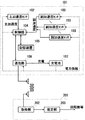
本実施形態においては、飛翔体の重心に測定ユニットが固定される。図1は、本発明の実施形態に係る飛翔体の内部に固定される測定ユニットおよび飛翔体の外部に用意される測定装置の概要構成を示す説明図である。以下、本図を参照して説明する。
(Measurement unit)
In the present embodiment, the measurement unit is fixed to the center of gravity of the projectile. FIG. 1 is an explanatory view showing a schematic configuration of a measurement unit fixed to the inside of a projectile according to an embodiment of the present invention and a measurement device prepared outside the projectile. This will be described below with reference to this figure.
測定ユニット101には、主加速度センサ102と副加速度センサ103の2種類の3軸加速度センサが固定されている。本実施形態では、これらの加速度センサを利用することにより、飛翔体の回転の様子を測定する。
In the
なお、ジャイロセンサーを利用しても回転を測定することは可能である。しかしながら、一般に、ジャイロセンサーはサイズが大きく、消費電力も大きい。一方、本実施形態で採用するように、加速度センサは、安価で、小型化が可能であり、消費電力も小さいという利点を有する。 In addition, it is possible to measure rotation also using a gyro sensor. However, in general, gyro sensors are large in size and power consumption is also large. On the other hand, as employed in the present embodiment, the acceleration sensor is inexpensive, can be miniaturized, and has low power consumption.
さて、主加速度センサ102は、飛翔体の重心もしくは重心の近傍(重心から所定の重心誤差範囲内)に固定される。主加速度センサ102は、飛翔体の移動に起因する加速度を主として測定する。
The
副加速度センサ103は、飛翔体の重心から離間して飛翔体の内部に固定される。副加速度センサ103は、飛翔体の回転に起因する加速度を主として測定する。
The
副加速度センサ103としては、少なくとも3つの高加速度センサを採用することが望ましい。主加速度センサ102からこの3つの高加速度センサに向かう3つの変位ベクトルは、互いにほぼ(所定の方向誤差範囲内で)直交することが望ましい。また、3つの変位ベクトルの長さは、ほぼ(所定の長さ誤差範囲内で)等しくなるように構成することができる。
It is desirable to employ at least three high acceleration sensors as the
たとえば、野球の硬式球やゴルフボールは、芯材の周囲に弾性体を巻き付けたり充填したりした上で、外殻を設置することによって形成される。したがって、測定ユニット101は、この芯材の中心に固定すれば良い。また、砲丸は一様な金属で形成されるので、その中心に測定ユニット101を配置すれば良い。
For example, a baseball ball or golf ball is formed by placing an outer shell after winding or filling an elastic body around a core material. Therefore, the
このほか、野球の軟式球、サッカーボール、テニスボール、バレーボール等の中空のボールに対しては、ボールの外殻から重心近傍までの支柱、支持枝、支持棒、支持バネ等、支持弾性体を設けてボールの中心に測定ユニットを配置すれば良い。 In addition, for hollow balls such as baseball balls, soccer balls, tennis balls, volleyballs, etc., support elastic bodies such as pillars from the outer shell of the ball to the vicinity of the center of gravity, supporting branches, supporting rods, supporting springs, etc. It is sufficient to provide and arrange the measurement unit at the center of the ball.
このほか、スポーツで利用される槍、円盤、ハンマー、砲丸等に対しても、その重心に測定ユニットを固定することで、回転の様子を測定することが可能である。 In addition to this, it is possible to measure the state of rotation by fixing the measurement unit to the center of gravity of a rod, a disk, a hammer, a gun shot, etc. used in sports.
測定ユニット101の各部は、制御部104により制御される。制御部104は、飛翔体が飛翔している間、主加速度センサ102および副加速度センサ103から主加速度および副加速度の測定結果を読み出して、記憶装置105に記録する。記憶装置105としては、RAM(Random Access Memory)、SSD(Solid State Disk)、フラッシュメモリ等を採用することができる。
The respective units of the
記憶装置105に記録された結果は、近距離無線通信により、飛翔体の外部へ伝達される。制御部104は、通信部106を制御して外部との近距離無線通信が可能か否かを検出し、可能であれば、記憶装置105から読み出した加速度の測定結果を外部へ伝達する。
The result recorded in the
また、通信部106が有する通信用のアンテナもしくは別途用意された回路等を用いて、充電池107への充電が行われる。
In addition, charging of the
たとえば、飛翔体を一定の磁界の中に配置して回転させると、電磁誘導により電力が生じるので、これを充電池107に充電すれば良い。充電池107から、主加速度センサ102、副加速度センサ103、制御部104、記憶装置105、通信部106を動作させるための電力を供給する。
For example, when the projectile is placed in a constant magnetic field and rotated, power is generated by electromagnetic induction, so that the
なお、この回転を一定の角速度で行うことで、測定ユニット101の較正をすることも可能である。較正の手法については後述する。
It is also possible to calibrate the measuring
なお、有線接続のためのコネクタを介して通信や充電を行うことも可能であるし、飛翔体から測定ユニット101を取り外して通信や充電を行うこととしても良い。
Note that communication and charging may be performed via a connector for wired connection, or the
以下、理解を容易にするため、野球の硬式球を飛翔体の例として説明する。 Hereinafter, in order to facilitate understanding, a hardball of baseball will be described as an example of a flying object.
飛翔体が飛翔している間、飛翔体は自由落下をすることになるので、主加速度センサ102により測定される加速度は、主としてマグヌス力や抵抗力に起因するものである。これは、一般には、飛翔体が回転することによって生じる加速度よりも小さいことが多い。そこで、副加速度センサ103の測定可能範囲を主加速度センサ102の測定可能範囲よりも広いものとすることで、より正確な測定が可能となる。主加速度センサ102の測定可能範囲、副加速度センサ103の測定可能範囲は、当該飛翔体に想定される移動速度や回転速度に応じた加速度が測定できるようにすることが望ましい。これらは、実験によって定めることが可能である。
Since the projectile falls freely while the projectile is flying, the acceleration measured by the
たとえば、野球の硬式球をピッチャーが投げた変化球の回転の様子を調べるには、主加速度センサ102と各副加速度センサ(高加速度センサ)103との距離を約7mmとした場合、主加速度センサ102として、5G程度の測定範囲の低加速度センサを採用し、副加速度センサ103として、200G程度の測定範囲の高加速度センサを採用すれば良い。これらの数値は、用途や目的に応じて、適宜変更が可能である。
For example, in order to investigate how the pitcher rotates the pitched ball of a baseball-style hardball, if the distance between the
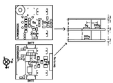
図2は、測定ユニットに固定される加速度センサの位置を示す説明図である。以下、本図を参照して説明する。 FIG. 2 is an explanatory view showing the position of the acceleration sensor fixed to the measurement unit. This will be described below with reference to this figure.
測定ユニット101の底基板(本図左下)および中基板(本図左上)には、主加速度センサ102が1つの位置「5g」に、副加速度センサ103が3つの位置「200g」に、それぞれ配置されている。底基板と中基板は、側面図(本図右)に示すように離間して固定されており、側面図において、主加速度センサ102の右、手前、下に等距離(7mm)だけ離間して、副加速度センサ103が配置されている。このような基板に基づいて構成された測定ユニットは、小型で、重量約16gと非常に軽量であり、野球の硬式球の芯材の中に組み込むことが可能である。
The
(測定装置)
飛翔体の外部に用意される測定装置201は、測定ユニット101から飛翔体が飛翔している間に測定された加速度を取得して、飛翔体の単位時間あたりの回転数等を推定する。この測定装置201は、典型的には、プログラムをコンピュータが実行することによって実現される。当該コンピュータは、各種の出力装置や入力装置に接続され、これらの機器と情報を送受する。
(measuring device)
The measuring
コンピュータにて実行されるプログラムは、当該コンピュータが通信可能に接続されたサーバにより配布、販売することができるほか、CD-ROM(Compact Disk Read Only Memory)やフラッシュメモリ、EEPROM(Electrically Erasable Programmable ROM)などの非一時的(non-transitory)な情報記録媒体に記録した上で、当該情報記録媒体を配布、販売等することも可能である。 Programs executed by a computer can be distributed and sold by a server to which the computer is communicably connected, and can be a compact disk read only memory (CD-ROM), a flash memory, or an EEPROM (Electrically Erasable Programmable ROM). And the like, and it is also possible to distribute, sell, etc. the information recording medium after recording on a non-transitory information recording medium.
プログラムは、コンピュータが有するハードディスク、ソリッドステートドライブ、フラッシュメモリ、EEPROM等などの非一時的な情報記録媒体にインストールされる。すると、当該コンピュータにより、本実施形態における情報処理装置が実現されることになる。一般的には、コンピュータのCPU(Central Processing Unit)は、コンピュータのOS(Operating System)による管理の下、情報記録媒体からRAM(Random Access Memory)へプログラムを読み出してから、当該プログラムに含まれるコードを解釈、実行する。ただし、CPUがアクセス可能なメモリ空間内に情報記録媒体をマッピングできるようなアーキテクチャでは、RAMへの明示的なプログラムのロードは不要なこともある。なお、プログラムの実行の過程で必要とされる各種情報は、RAM内に一時的(temporary)に記録しておくことができる。 The program is installed on a non-transitory information recording medium such as a hard disk of a computer, a solid state drive, a flash memory, an EEPROM or the like. Then, the information processing apparatus according to the present embodiment is realized by the computer. Generally, a central processing unit (CPU) of a computer reads out a program from an information recording medium to a random access memory (RAM) under the control of an operating system (OS) of the computer, and then codes included in the program. Interpret and execute. However, in an architecture in which the information recording medium can be mapped in a memory space accessible by the CPU, explicit program loading to the RAM may not be necessary. In addition, various information required in the process of program execution can be temporarily recorded in the RAM (temporary).
なお、汎用のコンピュータにより本実施形態の情報処理装置を実現するのではなく、専用の電子回路を用いて本実施形態の情報処理装置を構成することも可能である。この態様では、プログラムを電子回路の配線図やタイミングチャート等を生成するための素材として利用することもできる。このような態様では、プログラムに定められる仕様を満たすような電子回路がFPGA(Field Programmable Gate Array)やASIC(Application Specific Integrated Circuit)により構成され、当該電子回路は、当該プログラムに定められた機能を果たす専用機器として機能して、本実施形態の情報処理装置を実現する。 Note that the information processing apparatus of the present embodiment can be configured using a dedicated electronic circuit instead of realizing the information processing apparatus of the present embodiment using a general-purpose computer. In this aspect, the program can also be used as a material for generating a wiring diagram or timing chart of an electronic circuit. In such an aspect, an electronic circuit satisfying a specification defined in a program is configured by a field programmable gate array (FPGA) or an application specific integrated circuit (ASIC), and the electronic circuit has a function defined in the program. The device functions as a dedicated device to realize the information processing apparatus of the present embodiment.
以下では、理解を容易にするため、測定装置201は、コンピュータがプログラムを実行することによって実現される態様を想定して説明する。さて、測定装置201は、取得部202、推定部203を備える。
In the following, in order to facilitate understanding, the measuring
取得部202は、飛翔体が飛翔している間に主加速度センサ102により測定された主加速度、および、副加速度センサ103により測定された副加速度を取得する。上記のように、飛翔体内に配置された測定ユニット101から、無線通信により、これらの情報を取得することが可能である。
The
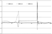
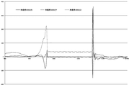
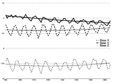
図3Aは、野球のボールの投球動作を開始してからキャッチするまでの間に主加速度センサにて測定された各加速度の変化を示すグラフである。図3Bは、野球のボールの投球動作を開始してからキャッチするまでの間に副加速度センサ(X軸方向)にて測定された各加速度の変化を示すグラフである。図3Cは、野球のボールの投球動作を開始してからキャッチするまでの間に副加速度センサ(Y軸方向)にて測定された各加速度の変化を示すグラフである。図3Dは、野球のボールの投球動作を開始してからキャッチするまでの間に副加速度センサ(Z軸方向)にて測定された各加速度の変化を示すグラフである。これらの図に示すように、4つの加速度センサから12個の加速度成分の時間変化の計測結果が得られている。 FIG. 3A is a graph showing a change in each acceleration measured by the main acceleration sensor from the start of a pitching motion of a baseball to the time of catching. FIG. 3B is a graph showing changes in each acceleration measured by the secondary acceleration sensor (in the X-axis direction) from the start of the throwing motion of the baseball to the time of catching. FIG. 3C is a graph showing a change in each acceleration measured by the secondary acceleration sensor (in the Y-axis direction) from the start of the throwing motion of the baseball to the time of catching. FIG. 3D is a graph showing changes in each acceleration measured by the secondary acceleration sensor (in the Z-axis direction) from the start of the throwing motion of the baseball to the time of catching. As shown to these figures, the measurement result of the time change of 12 acceleration components is obtained from four acceleration sensors.
投球動作が終わった瞬間(時間軸980付近)、および、ボールがキャッチされた瞬間(時間軸1080付近)には、その衝撃で、一部の加速度が急峻なピークもしくは谷に至る。したがって、これらの間から、飛翔中の加速度の測定値を抽出することが可能である。 At the moment when the throwing operation is finished (near time axis 980) and the moment the ball is caught (near time axis 1080), part of the acceleration reaches a sharp peak or valley due to the impact. Therefore, it is possible to extract the measurement value of the acceleration in flight from among these.
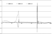
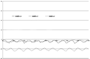
図4Aは、野球のボールが飛翔している間に主加速度センサにて測定された各加速度の変化を示すグラフである。図4Bは、野球のボールが飛翔している間に副加速度センサ(X軸)にて測定された各加速度の変化を示すグラフである。図4Cは、野球のボールが飛翔している間に副加速度センサ(Y軸)にて測定された各加速度の変化を示すグラフである。図4Dは、野球のボールが飛翔している間に副加速度センサ(Z軸)にて測定された各加速度の変化を示すグラフである。これらの図からは、ボールが飛翔している間(時間軸990-1070)の加速度の各測定値が、ボールの回転に応じた周期で上下に変動しつつ、ボールにかかる抗力に応じた増減トレンドに沿って変化していることがわかる。 FIG. 4A is a graph showing changes in each acceleration measured by the main acceleration sensor while the baseball is flying. FIG. 4B is a graph showing changes in each acceleration measured by the secondary acceleration sensor (X axis) while the baseball ball is flying. FIG. 4C is a graph showing a change in each acceleration measured by the secondary acceleration sensor (Y axis) while the baseball is flying. FIG. 4D is a graph showing a change in each acceleration measured by the secondary acceleration sensor (Z axis) while the baseball is flying. From these figures, while the ball is flying (time axis 990-1070), each measured value of acceleration changes up and down in a cycle corresponding to the rotation of the ball, and increases or decreases according to the drag applied to the ball It turns out that it is changing along the trend.
さて、推定部203は、このようにして取得された主加速度及び副加速度から、飛翔体の単位時間あたりの回転数(角速度)、飛翔体における回転中心の位置、回転軸の方向(飛翔体に固定された座標系における回転軸方向や、慣性座標系における回転軸方向)等を、所定の手順で、最尤推定により推定する。
From the main acceleration and the sub acceleration thus obtained, the
以下では、推定手法に対する理解を容易にするため、主加速度センサ102から各副加速度センサ103へ向かう3つの変位ベクトルは直交し、等距離dL=7mmだけ離間している例により説明を行う。そして、各変位ベクトルの方向を、測定ユニット101ならびに飛翔体に固定された座標系(飛翔体座標系)のX軸、Y軸、Z軸と呼ぶこととする。
In the following, in order to facilitate understanding of the estimation method, three displacement vectors from the
(角速度/単位時間あたりの回転数)
飛翔体内の特定位置の慣性座標系(地面に固定された座標系)における位置ベクトルxは、回転中心の位置ベクトルx0、回転中心からの飛翔体座標系における半径ベクトルr、回転軸ベクトルl、角速度ω、時刻t、に対する回転マトリックスMωtに対して、以下のように表現することができる。
(Angular velocity / number of revolutions per unit time)
The position vector x in the inertial coordinate system (coordinate system fixed to the ground) of the specific position in the projectile is the position vector x 0 of the rotation center, the radius vector r in the projectile coordinate system from the rotation center, the rotation axis vector l, The rotation matrix M ωt with respect to the angular velocity ω and the time t can be expressed as follows.

これを時間で微分すると、以下のように、速度および加速度が求められる。なお、時間微分は、変数の上にドットを記載することで表現する。 If this is differentiated by time, the velocity and acceleration can be obtained as follows. Note that time differentiation is expressed by writing dots on variables.
ここで、飛翔体座標系では、半径ベクトルrは時間変化しないので、半径ベクトルrを時間で1階微分した結果はゼロベクトルとなる。 Here, in the projectile coordinate system, the radius vector r does not change with time, so the result of first-order differentiation of the radius vector r with respect to time becomes a zero vector.
すると、回転マトリックスMωtの2階微分は、以下のように変形することができる。 Then, the second derivative of the rotation matrix M ωt can be transformed as follows.
![]()
![]()
したがって、位置ベクトルxの2階微分は、以下のように表記できる。 Therefore, the second derivative of the position vector x can be expressed as follows.
重力加速度g、抗力加速度adとすると、以下の関係が成立する。 Gravitational acceleration g, when the drag acceleration a d, the following relationship is established.
これに対して、左から回転マトリックスMωtの逆行列を乗じると、半径ベクトルrの2階微分は、以下のように表記できる。 On the other hand, the second derivative of the radius vector r can be expressed as follows by multiplying the inverse of the rotation matrix M ωt from the left.
なお、回転マトリックスMωtの逆行列は、回転軸ベクトルlの周りに角度ωtだけ逆回転したものである。また、回転軸ベクトルlは、回転マトリックスMωtによる回転の影響を受けない。したがって、以下の関係が成立する。 Note that the inverse matrix of the rotation matrix M ωt is the one rotated back by an angle ωt around the rotation axis vector l. Also, the rotation axis vector l is not affected by the rotation by the rotation matrix M ωt . Therefore, the following relationship is established.
![]()
![]()
また、lTrは、回転軸ベクトルlと半径ベクトルrの内積(l・r)である。 Further, l T r is the inner product of the rotation axis vector l and a radius vector r (l · r).
さて、以下では、変数の添字として、主加速度センサ102についてはB、副加速度センサ103については、各軸方向にX, Y, Zを採用する。主加速度センサ102(B)と、副加速度センサ103(X, Y, Z)の回転軸周りの回転角をθX, θY, θZとする。すると、主加速度センサ102(B)により測定されるべき加速度(主加速度)と、副加速度センサ103(X, Y, Z)により測定されるべき加速度(3つの副加速度)と、は、以下のように表現できる。
Now, hereinafter, as subscripts of variables, B is adopted for the
これを1周期分で時間平均すると、以下のように表現できる。時間平均は、変数の上にバーを引くことで表現する。 If this is time-averaged in one cycle, it can be expressed as follows. The time average is expressed by pulling a bar above the variable.
副加速度センサ103(X, Y, Z)により測定された加速度の時間平均から、主加速度センサ102(B)により測定された加速度の時間平均を減算する。 The time average of the acceleration measured by the main acceleration sensor 102 (B) is subtracted from the time average of the acceleration measured by the secondary acceleration sensor 103 (X, Y, Z).
一方、主加速度センサ102(B)から副加速度センサ103(X, Y, Z)へ向かう変位ベクトルは、以下のように表現できる。なお、変位ベクトルが直交しない場合や長さが異なる場合には、それに応じて以下の数式の各要素の数値を変更すれば良い。 On the other hand, the displacement vector from the main acceleration sensor 102 (B) to the sub acceleration sensor 103 (X, Y, Z) can be expressed as follows. In the case where the displacement vectors are not orthogonal or the lengths are different, the numerical values of each element of the following formula may be changed accordingly.
これらを成分表示すると、以下のように表現できる。なお、当該1周期内において回転軸ベクトルlは、時間変化しないものと仮定して、成分表記lx, ly, lzでは上のバーを省略している。 When these are displayed as components, they can be expressed as follows. In addition, assuming that the rotation axis vector l does not change with time in the one period, the upper bar is omitted in the component notation l x , l y and l z .
回転軸ベクトルlの長さは1であるから、以下のように角速度ωを求めることができる。なお、角速度ωは、単位時間あたりの回転数に2π(1回転360度をラジアンで表記した値)を乗じた値である。 Since the length of the rotation axis vector l is 1, the angular velocity ω can be obtained as follows. The angular velocity ω is a value obtained by multiplying the number of rotations per unit time by 2π (a value obtained by writing 360 degrees of one rotation in radians).
角速度ωが求められれば、[数14]の第1、4、7式から、lx, ly, lzの大きさを計算することができ、残りの式を参照することでlx, ly, lzの符号(プラスマイナス)を定めることができる。 As long sought angular velocity ω is from the 1,4,7 equation [Expression 14], l x, l y , it is possible to calculate the magnitude of l z, l x by reference to the remaining formulas, The signs (plus and minus) of l y and l z can be determined.
上記の計算手法では、ωを求めてからlx, ly, lzを計算している。しかしながら、[数14]における方程式は9個であるのに対して、未知数はω, lx, ly, lzの4つであり、式の数の方が多くなっている。したがって、lx, ly, lzの自乗和が1である、という制約の元で、誤差を最小化するように、未知数ω, lx, ly, lzを最尤推定することとしても良い。 In the above calculation method, l x , l y and l z are calculated after finding ω. However, while the number of equations in [Equation 14] is nine, the unknowns are four of ω, l x , l y , and l z , and the number of equations is larger. Therefore, under the constraint that the sum of squares of l x , l y and l z is 1, as the maximum likelihood estimation of the unknowns ω, l x , l y and l z so as to minimize the error Also good.
また、時間平均は、回転の1周期に対して行うことが理想的であるが、その周期(角速度ω)を求めることが目的であるから、回転の1周期についての時間平均ではなく、飛翔体が飛翔している間の全時間の時間平均をとっても良いし、その中から角速度を求めたい区間を適宜抽出して時間平均を求めることとしても良い。 In addition, although it is ideal that time averaging is performed for one cycle of rotation, it is an object to obtain the cycle (angular velocity ω), and therefore the flying object is not the time average for one cycle of rotation. A time average of all the time during the flight may be taken, or a section for which an angular velocity is desired to be obtained may be appropriately extracted to obtain a time average.
上記の説明では、副加速度センサ103は3つとしているが、より多くの副加速度センサ103を用意しても良い。この場合には、未知数の数に対して得られる制約条件の数が過剰となるので、誤差が最小となるように推定を行うことで、正確な測定が可能となる。
In the above description, the number of
(飛翔体座標系における回転中心)
主加速度センサ102は、飛翔体の重心の近傍(所定の重心誤差範囲内)に固定されるが、飛翔体の回転中心は、主加速度センサ102からずれていることも多い。このため、主加速度センサ102および副加速度センサ103にて測定される主加速度、副加速度は、位相がずれている。
(Rotation center in spacecraft coordinate system)
Although the
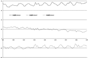
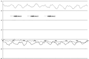
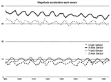
図5は、各加速度センサにより測定された加速度の大きさの時間変化を示すグラフである。以下、本図を参照して説明する。 FIG. 5 is a graph showing temporal changes in magnitude of acceleration measured by each acceleration sensor. This will be described below with reference to this figure.
本図では、飛翔体が飛翔している間に主加速度センサ102および副加速度センサ103により測定された加速度の大きさの一例を図示しており、各測定結果は、上から順に、X軸方向の副加速度センサ103の(副)加速度の大きさ、Z軸方向の副加速度センサ103の(副)加速度の大きさ、原点(Origin)の主加速度センサ102による(主)加速度の大きさ、Y軸方向の副加速度センサ103の(副)加速度の大きさである。
In this figure, an example of the magnitude of the acceleration measured by the
各グラフの位相のずれは、回転軸方向から見たセンサ位置のずれ角度に相当する。 The phase shift of each graph corresponds to the shift angle of the sensor position viewed from the rotational axis direction.
本図に示す例では、主加速度(Origin)およびY軸方向の副加速度の大きさが小さく、位相もほぼ揃っていることから、回転軸は、Y軸とほぼ同じ方向を向いていることがわかる。したがって、X軸方向、Z軸方向の副加速度の位相のずれは、90度に近いはずである。 In the example shown in the figure, since the magnitudes of the main acceleration (Origin) and the secondary acceleration in the Y-axis direction are small and the phases are almost the same, it is possible that the rotation axis is almost in the same direction as the Y-axis. Recognize. Therefore, the phase shift of the secondary acceleration in the X-axis direction and the Z-axis direction should be close to 90 degrees.
回転軸ベクトルlは、上記の手法により計算できるので、回転軸方向から主加速度センサ102および副加速度センサ103を見たときに、各センサ102、103が回転軸周りに配置される角度が、測定された加速度における位相ずれとできるだけ一致し、位相誤差が最小になるように、回転中心座標を最小自乗法や最急降下法などの最尤推定にて推定すれば、回転中心を決定することができる。
Since the rotation axis vector l can be calculated by the above method, when the
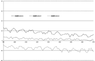
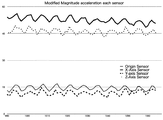
図6は、各加速度センサにより測定された加速度の大きさの時間変化の位相を揃えたグラフである。本図では、位相のずれをできるだけ揃えているため、各グラフのピーク位置が同期している。 FIG. 6 is a graph in which the phases of the time change of the magnitude of the acceleration measured by each acceleration sensor are aligned. In this figure, the peak positions of the graphs are synchronized because the phase shifts are aligned as much as possible.
(慣性座標系における回転軸方向)
上記手法では、飛翔体座標系における回転軸ベクトルの各成分が計算されている。したがって、慣性座標系において飛翔体がどのような回転軸周りをまわっているか、は、慣性座標系と飛翔体座標系との間の座標変換が必要である。
(Rotation axis direction in inertial coordinate system)
In the above method, each component of the rotation axis vector in the projectile coordinate system is calculated. Therefore, about what rotation axis the projectile is rotating in the inertial coordinate system, coordinate conversion between the inertial coordinate system and the projectile coordinate system is required.
ここで、主加速度センサ102および副加速度センサ103は、回転による遠心力と、飛翔体に対する抗力(重力、速度を落とす摩擦力、軌跡を変化させるマグヌス力等を含む。)と、の影響を観測する。
Here, the
ここで、遠心力は、角速度と回転軸が変化しなければ一定のはずである。しかしながら、
(1)上記手法によって求められた回転中心ならびに回転軸周りを各センサが回転していると想定した場合に観測されるべき加速度と、
(2)実際に観測される加速度と、
には、ずれが生じる。このずれは、抗力が時間変化していることに起因するものである。
Here, the centrifugal force should be constant if the angular velocity and the rotation axis do not change. However,
(1) Accelerations to be observed when it is assumed that each sensor is rotating around the rotation center and the rotation axis obtained by the above method
(2) Acceleration actually observed,
, There is a gap. This deviation is due to the fact that the drag is changing with time.
ここで、角速度が一定であれば、抗力の大きさはボールの速度に応じて定まる。抗力の向きは、慣性系における飛翔体の速度ベクトルの変化を表す。 Here, if the angular velocity is constant, the magnitude of the drag is determined according to the velocity of the ball. The direction of drag represents a change in the velocity vector of the projectile in the inertial system.
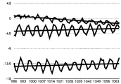
図7Aは、主加速度センサにより測定された加速度の各成分の時間変化の増減トレンドとトレンド直線を示すグラフである。図7Bは、主加速度センサにより測定された加速度の各成分の時間変化の増減トレンドとトレンド曲線を示すグラフである。以下、これらの図を参照して説明する。 FIG. 7A is a graph showing an increasing / decreasing trend of the time change of each component of the acceleration measured by the main acceleration sensor and a trend line. FIG. 7B is a graph showing an increasing / decreasing trend of the time change of each component of acceleration measured by the main acceleration sensor and a trend curve. Hereinafter, description will be made with reference to these figures.
これらの図では、遠心加速度の寄与が少ない主加速度センサ102により測定された加速度の各成分を示している。これらの図においては、上の主加速度成分は次第に減少しており、中および下の主加速度成分は一旦減少した後、次第に増加している。
In these figures, each component of the acceleration measured by the
この減少、増加のトレンドは、最小自乗法により分析することができる。図7Aは、最小自乗法により求められた増減のトレンドを表すトレンド直線を図示している。図7Bは、最小自乗法でトレンドを二次曲線に回帰させた様子を図示している。 The decreasing and increasing trend can be analyzed by the method of least squares. FIG. 7A illustrates a trend line representing the trend of increase and decrease determined by the method of least squares. FIG. 7B illustrates how the trend is regressed to a quadratic curve by the method of least squares.
トレンド直線の傾きや、トレンド曲線の傾きならびに変化は、飛翔体座標系における抗力の向きの変化を表している。 The inclination of the trend line and the inclination and change of the trend curve represent the change in the direction of drag in the projectile coordinate system.
ここで、飛翔体が短時間飛翔している間に飛翔体に加わる力は、重力、抗力、マグヌス力に分類することができる。 Here, the force applied to the projectile while the projectile flies for a short time can be classified into gravity, drag, and magnus.
抗力は、飛翔体の進行方向と反対向きの力であり、飛翔体の速さを下げる効果を有するが、飛翔体の進行方向には、影響を及ぼさない。飛翔体の進行方向を変化させるのは、重力とマグヌス力である。 The drag is a force in the direction opposite to the traveling direction of the projectile, and has the effect of reducing the speed of the projectile, but does not affect the traveling direction of the projectile. Gravity and the Magnus force change the direction of flight of the projectile.
そこで、[数10]から遠心加速度成分を除去して外力加速度とする。 Therefore, the centrifugal acceleration component is removed from [Equation 10] to obtain an external force acceleration.
さらに、図7Bに示すように、主加速度センサ102にて測定された、飛翔体座標系のX, Y, Z軸方向の各成分について最小自乗法を用いて、外力加速度を二次式で近似する。
Furthermore, as shown in FIG. 7B, the external force acceleration is approximated by a quadratic equation using the least squares method for each component of the project object coordinate system in the X, Y, Z directions measured by the
ここで、ad,tは、時刻tにおける外力加速度ベクトルである。 Here, a d, t is an external force acceleration vector at time t.
飛翔体の飛翔している時間区間[s,e]における飛翔体の進行方向の変化Δuは、以下のように計算することができる。 The change Δu in the traveling direction of the projectile in the flying time interval [s, e] of the projectile can be calculated as follows.
飛翔体の進行方向の変化を分析するための座標系を考える。この座標系では、x軸、y軸、z軸のように、座標軸を小文字で表記する。 Consider a coordinate system to analyze changes in the direction of flight of the projectile. In this coordinate system, coordinate axes are written in lower case letters, such as x-axis, y-axis and z-axis.
まず、z軸は、ベクトル(-Δu)の向きに伸びるように設定する。z軸正の向きの方向ベクトルkは、以下のように計算できる。
k = (-Δu)/|Δu|
First, the z-axis is set to extend in the direction of the vector (-Δu). The direction vector k in the z-axis positive direction can be calculated as follows.
k = (-Δu) / | Δu |
次に、飛翔体の投げ出し方向をy軸に設定する。y軸正の向きの方向ベクトルjは、以下のように計算できる。
j = ad,s/|ad,s|
Next, the throwing direction of the projectile is set to the y-axis. The direction vector j in the positive y-axis direction can be calculated as follows.
j = a d, s / | a d, s |
最後に、x軸正の向きの方向ベクトルiは、以下のように計算する。
i = j×k
Finally, the direction vector i in the x-axis positive direction is calculated as follows.
i = j × k
このように、3つの方向ベクトルi, j, kによりx軸、y軸、z軸が定められる座標系により、飛翔体に対する重力とマグヌス力の影響を表現することができる。すなわち、y軸は、飛翔体の進行方向を表し、z軸は、飛翔体の進行方向を変化させる重力およびマグヌス力の合力の方向を表すことになる。 Thus, the effects of gravity and magnus on the projectile can be expressed by a coordinate system in which the x-axis, y-axis, and z-axis are defined by the three direction vectors i, j, k. That is, the y-axis represents the traveling direction of the projectile, and the z-axis represents the direction of the combined force of gravity and magnus that changes the traveling direction of the projectile.
(測定の手順)
図8は、本実施形態に係る測定方法の実行手順を示すフローチャートである。以下、本図を参照して説明する。
(Procedure of measurement)
FIG. 8 is a flowchart showing an execution procedure of the measurement method according to the present embodiment. This will be described below with reference to this figure.
まず、ユーザは、測定ユニット101が内部に固定された飛翔体を測定装置201に近接させあるいは接続することにより、飛翔体を測定装置201に装着して、測定ユニット101を充電する(ステップS301)。上記のように、充電に電磁誘導を利用する際には、一定の磁界の中で飛翔体101を回転させることで、近距離無線通信用のアンテナを介して電力を誘導して、充電池107を充電すれば良い。また、測定装置201側で生じさせる磁界を変化させることにより、充電池107が充電されるようにしても良い。
First, the user mounts the projectile on the
次に、ユーザは、測定装置201から飛翔体を取り外す(ステップS302)。すると、測定ユニット101の制御部104は、通信部106を介する測定装置201との通信ができなくなったことを検知して、主加速度センサ102および副加速度センサ103による加速度の検出ならびに当該加速度の記憶装置105への記録を開始する(ステップS303)。
Next, the user removes the projectile from the measuring device 201 (step S302). Then, the control unit 104 of the
この後、ユーザは、飛翔体の投擲等を実行する(ステップS304)。すると、飛翔体は空中を飛翔する。飛翔している間も、加速度の検出および記録は継続している。 After this, the user executes throwing of a flying object, etc. (step S304). Then, the flight vehicle flies in the air. While flying, detection and recording of acceleration is continuing.
そして、飛翔体をキャッチもしくは回収したユーザは、当該飛翔体を測定装置201に近接させあるいは接続することにより、飛翔体を測定装置201に再度装着する(ステップS305)。
Then, the user who has caught or recovered the flying object reattaches the flying object to the
すると、測定ユニット101の制御部104は、通信部106を介した通信が可能となったことを検知して、加速度の検出および記録を停止し(ステップS306)、測定装置201の取得部202との通信を開始する。すると、測定装置201の取得部202は、測定ユニット101から、記憶装置105に記録された加速度を取得する(ステップS307)。
Then, the control unit 104 of the
加速度の取得が完了したら、測定装置201の推定部203は、上記の手法に基づいて、飛翔体の角速度(単位時間あたりの回転数)、回転軸ベクトルの飛翔体座標系・慣性座標系における時間変化等を推定して出力し(ステップS308)、本処理を終了する。
When the acquisition of the acceleration is completed, the
なお、加速度の取得が完了した後は、次の測定の準備のため、測定ユニット101の充電池107に対する充電が開始されることになる(ステップS301参照)。また、測定ユニット101に対する充電開始のタイミングは、飛翔体を測定装置201に装着した時点としても良い。このように構成すると、加速度の取得をする際に充電も自動的に行われるので、充電忘れを防止することができるほか、別途の充電が不要であるから、1回測定してから次に測定するまでの時間や手間を節約できる。
In addition, after acquisition of the acceleration is completed, charging of the
このほか、上記のように、充電は、必ずしも電磁誘導による充電でなくても良い。たとえば、通信部106に接続された通信用のアンテナ以外に別途用意された回路等を用いることも可能であるし、有線接続のためのコネクタを介して通信や充電を行うことも可能である。また、飛翔体から測定ユニット101を取り外して通信や充電を行うこととしても良い。
Besides, as described above, charging may not necessarily be charging by electromagnetic induction. For example, a circuit or the like separately prepared other than the communication antenna connected to the
(較正)
以下では、主加速度センサ102、副加速度センサ103の測定値を較正する手法について説明する。
(calibration)
Below, the method to calibrate the measured value of the
上記のように、測定ユニット101に対する充電は、飛翔体を磁界の中で回転させることにより行うことが可能である。このときの飛翔体の単位時間あたりの回転数は、外部から制御・観察が可能である。
As described above, charging of the
そこで、外部から与えた回転における単位時間あたりの回転数と、当該回転測定ユニット101において測定された主加速度、副加速度の時間変化や測定装置201にて推定された単位時間あたりの回転数および慣性座標系における回転軸の向きと、を対比することで、主加速度センサ102、副加速度センサ103の出力値を較正したり、これらの位置の誤差を補正することが可能となる。
Therefore, the number of rotations per unit time in the externally applied rotation, the main acceleration measured in the
上記実施例では、1つの主加速度センサ102を飛翔体座標系の原点に配置し、3つの副加速度センサ103を飛翔体座標系のX, Y, Z軸上に配置していたが、副加速度センサ103の数を減らしても良い。
In the above embodiment, one
特許文献1では、飛翔体の重心に配置された3軸加速度センサの測定結果をウェーブレット変換して、単位時間あたりの回転数を求めている。
In
1つもしくは2つの副加速度センサ103にて測定された加速度(3つもしくは6つの成分の時間変化)から、主加速度センサ102にて測定された加速度(3つの成分の時間変化)を減算すれば、回転中心から離間した箇所において、主として回転に起因する加速度を取得することができる。
If the acceleration (time change of three components) measured by the
得られた加速度成分は、特許文献1にて測定される加速度成分よりも精度が高いと考えられる。したがって、特許文献1と同様にウェーブレット変換を適用することで単位時間あたりの回転数を求めることができるのは勿論、高速フーリエ変換などの、計算負荷の小さい分析手法によっても、高い精度で単位時間あたりの回転数を得ることができる。
The obtained acceleration component is considered to have higher accuracy than the acceleration component measured in
上記の[数15]においては、角速度を求めるために、主加速度センサ102により測定された主加速度のX, Y, Z成分、X軸方向の副加速度センサ103により測定された副加速度のX成分、Y軸方向の副加速度センサ103により測定された副加速度のY成分、Z軸方向の副加速度センサ103により測定された副加速度のZ成分を参照している。
In the above [Equation 15], the X, Y, Z components of the main acceleration measured by the
たとえば、副加速度センサ103としてX軸方向の副加速度センサ103を1つだけ採用した場合には、
(1)副加速度のX成分から主加速度のX成分を減算した値、
(2)副加速度のY成分から主加速度のY成分を減算した値、
(3)副加速度のZ成分から主加速度のZ成分を減算した値、
のいずれか少なくとも1つを高速フーリエ変換して、基本周波数を求めることにより、単位時間あたりの回転数(基本周波数の逆数)を得ることができる。3つを採用して結果に相違がある場合は、多数決によっていずれかを選択したり、平均をとったり、加速度の変化が最も大きい成分から得られたものを選択する等によって、単位時間あたりの回転数を求めることができる。
For example, when only one
(1) A value obtained by subtracting the X component of the main acceleration from the X component of the sub acceleration
(2) A value obtained by subtracting the Y component of the main acceleration from the Y component of the sub acceleration
(3) A value obtained by subtracting the Z component of the main acceleration from the Z component of the sub acceleration
The number of rotations per unit time (reciprocal of the fundamental frequency) can be obtained by subjecting at least one of them to fast Fourier transform to obtain the fundamental frequency. If there are differences in the results by adopting three, the rotation per unit time by selecting one by majority, taking an average, or selecting the one obtained from the component with the largest change in acceleration, etc. You can find the number.
この態様では、回転軸の方向について十分な推定はできないが、副加速度センサを減らした簡易な構成で、従来よりも簡易な計算により、正確に単位時間あたりの回転数を求めることが可能となる。 In this aspect, although the direction of the rotation axis can not be sufficiently estimated, the number of rotations per unit time can be accurately determined by a simple configuration with a reduced number of secondary acceleration sensors and by a simpler calculation than the conventional one. .
(まとめ)
以上のように、本実施形態における測定装置は、
飛翔体の重心もしくは当該重心から所定の重心誤差範囲内に固定された主加速度センサが、前記飛翔体が飛翔する間に測定した主加速度と、前記重心から離間して前記飛翔体の内部に固定された副加速度センサが、前記飛翔体が飛翔する間に測定した副加速度と、を、取得する取得部、
前記取得された主加速度と、前記取得された副加速度と、から、前記飛翔体の単位時間当たりの回転数を最尤推定する推定部
を備える。
(Summary)
As described above, the measuring device in the present embodiment
The main acceleration sensor fixed within the gravity center of the projectile or within the predetermined gravity center error range from the gravity center, fixed within the projectile away from the gravity center and the main acceleration measured during the flight of the projectile An acquisition unit for acquiring the acquired secondary acceleration sensor and the secondary acceleration measured during the flight of the projectile;
And an estimation unit configured to perform maximum likelihood estimation on the number of revolutions per unit time of the projectile from the acquired primary acceleration and the acquired secondary acceleration.
また、本実施形態に係る測定装置において、
前記副加速度センサは、少なくとも3個の高加速度センサを含み、
前記主加速度センサから前記3個の高加速度センサへ向かう3個の変位ベクトルは、一次独立であり、
前記推定部は、前記飛翔体の角速度ベクトルを最尤推定する
ように構成することができる。
Moreover, in the measuring apparatus according to the present embodiment,
The secondary acceleration sensor includes at least three high acceleration sensors,
The three displacement vectors from the main acceleration sensor to the three high acceleration sensors are linearly independent,
The estimation unit may be configured to perform maximum likelihood estimation of an angular velocity vector of the projectile.
また、本実施形態に係る測定装置において、
前記3個の変位ベクトルは、所定の方向誤差範囲内で直交し、
前記3個の変位ベクトルの大きさは、所定の長さ誤差範囲内で等しい
ように構成することができる。
Moreover, in the measuring apparatus according to the present embodiment,
The three displacement vectors are orthogonal within a predetermined direction error range,
The magnitudes of the three displacement vectors may be configured to be equal within a predetermined length error range.
また、本実施形態に係る測定装置において、
前記主加速度センサにより測定可能な主加速度の大きさの範囲は、前記飛翔体が飛翔する間の前記重心の移動に係る加速度がとりうる範囲を含み、
前記副加速度センサにより測定可能な副加速度の大きさの範囲は、前記飛翔体が飛翔する間の前記飛翔体の回転に由来する加速度がとりうる範囲を含み、
前記副加速度センサにより測定可能な副加速度の大きさの範囲は、前記主加速度センサにより測定可能な主加速度の大きさの範囲よりも広い
ように構成することができる。
Moreover, in the measuring apparatus according to the present embodiment,
The range of the magnitude of the main acceleration that can be measured by the main acceleration sensor includes the range that can be taken by the acceleration related to the movement of the center of gravity during the flight of the projectile,
The range of the magnitude of the secondary acceleration that can be measured by the secondary acceleration sensor includes the range in which the acceleration derived from the rotation of the projectile can be taken while the projectile flies.
The range of magnitude of the secondary acceleration that can be measured by the secondary acceleration sensor can be configured to be wider than the range of the magnitude of the main acceleration that can be measured by the primary acceleration sensor.
また、本実施形態に係る測定装置において、
前記飛翔体が飛翔する間に前記主加速度センサおよび前記副加速度センサにより測定された主加速度および副加速度は、前記飛翔体の内部に配置された記憶装置に記録され、
前記取得部は、前記飛翔体の飛翔が終了した後に、近距離無線通信により、前記記録された主加速度および副加速度を、前記記憶装置から取得する
ように構成することができる。
Moreover, in the measuring apparatus according to the present embodiment,
The main acceleration and the sub acceleration measured by the main acceleration sensor and the sub acceleration sensor during the flight of the projectile are recorded in a storage device disposed inside the projectile,
The acquisition unit may be configured to acquire the recorded primary acceleration and secondary acceleration from the storage device by near field communication after the flight of the projectile ends.
また、本実施形態に係る測定装置において、
前記飛翔体の内部に配置され、前記近距離無線通信、および、前記記憶装置への記録ならびに取得を制御する制御部は、前記近距離無線通信を介して給電された電力を充電し、当該充電された電力により動作する
ように構成することができる。
Moreover, in the measuring apparatus according to the present embodiment,
A control unit disposed inside the projectile and controlling the near field communication and recording and acquisition in the storage device charges the power supplied via the near field communication, and the charging is performed. It can be configured to operate with reduced power.
本実施形態に係る測定方法は、
飛翔体の重心もしくは当該重心から所定の重心誤差範囲内に固定された主加速度センサが、前記飛翔体が飛翔する間に、主加速度を測定し、
前記重心から離間して前記飛翔体の内部に固定された副加速度センサが、前記飛翔体が飛翔する間に、副加速度を測定し、
情報処理装置が、前記測定された主加速度と、前記測定された副加速度と、を、取得し、
前記情報処理装置が、前記取得された主加速度と、前記取得された副加速度と、から、前記飛翔体の単位時間当たりの回転数を最尤推定する。
The measuring method according to the present embodiment is
The main acceleration sensor fixed within a predetermined center-of-gravity error range from the gravity center of the projectile or the gravity center measures the main acceleration during the flight of the projectile,
A secondary acceleration sensor fixed inside the projectile spaced from the center of gravity measures the secondary acceleration while the projectile flies.
The information processing apparatus acquires the measured primary acceleration and the measured secondary acceleration,
The information processing apparatus performs maximum likelihood estimation on the number of revolutions per unit time of the projectile from the acquired primary acceleration and the acquired secondary acceleration.
本実施形態に係るプログラムは、
コンピュータを、
飛翔体が飛翔する間に前記飛翔体の重心もしくは当該重心から所定の重心誤差範囲内に固定された主加速度センサにより測定された主加速度と、前記飛翔体が飛翔する間に前記重心から離間して前記飛翔体の内部に固定された副加速度センサにより測定された副加速度と、を、取得する取得部、
前記取得された主加速度と、前記取得された副加速度と、から、前記飛翔体の単位時間当たりの回転数を最尤推定する推定部
として機能させる。
The program according to the present embodiment is
Computer,
A main acceleration measured by a main acceleration sensor fixed within a predetermined barycentric error range from the barycenter of the projectile or the barycenter while the projectile flies, and a distance from the barycenter during the flight of the projectile An acquisition unit for acquiring an auxiliary acceleration measured by an auxiliary acceleration sensor fixed inside the projectile;
It functions as an estimation unit that performs maximum likelihood estimation of the number of revolutions per unit time of the projectile from the acquired primary acceleration and the acquired secondary acceleration.
本実施形態に係る非一時的なコンピュータ読取可能な情報記録媒体は、上記のプログラムを記録する。 The non-temporary computer-readable information recording medium according to the present embodiment records the above program.
本発明によれば、飛翔体の単位時間あたりの回転数を測定する測定装置、測定方法、これらをコンピュータにより実現するためのプログラム、ならびに、当該プログラムを記録した非一時的なコンピュータ読取可能な情報記録媒体を提供することができる。 According to the present invention, a measuring device and method for measuring the number of revolutions per unit time of a projectile, a program for realizing these by a computer, and non-temporary computer readable information recording the program A recording medium can be provided.
101 測定ユニット
102 主加速度センサ
103 副加速度センサ
104 制御部
105 記憶装置
106 通信部
107 充電池
201 測定装置
202 取得部
203 推定部
101 measuring unit
102 Main acceleration sensor
103 Secondary acceleration sensor
104 Control unit
105 storage device
106 Communication unit
107 rechargeable battery
201 Measuring device
202 Acquisition unit
203 Estimator
Claims (9)
前記取得された主加速度と、前記取得された副加速度と、から、前記飛翔体の単位時間当たりの回転数を最尤推定する推定部
を備えることを特徴とする測定装置。 The main acceleration sensor fixed within the gravity center of the projectile or within the predetermined gravity center error range from the gravity center, fixed within the projectile away from the gravity center and the main acceleration measured during the flight of the projectile An acquisition unit for acquiring the acquired secondary acceleration sensor and the secondary acceleration measured during the flight of the projectile;
A measurement apparatus comprising: an estimation unit that estimates the number of revolutions per unit time of the projectile by the maximum likelihood from the acquired main acceleration and the acquired subacceleration.
前記主加速度センサから前記3個の高加速度センサへ向かう3個の変位ベクトルは、一次独立であり、
前記推定部は、前記飛翔体の角速度ベクトルを最尤推定する
ことを特徴とする請求項1に記載の測定装置。 The secondary acceleration sensor includes at least three high acceleration sensors,
The three displacement vectors from the main acceleration sensor to the three high acceleration sensors are linearly independent,
The measurement apparatus according to claim 1, wherein the estimation unit performs maximum likelihood estimation on an angular velocity vector of the projectile.
前記3個の変位ベクトルの大きさは、所定の長さ誤差範囲内で等しい
ことを特徴とする請求項2に記載の測定装置。 The three displacement vectors are orthogonal within a predetermined direction error range,
The measurement device according to claim 2, wherein the magnitudes of the three displacement vectors are equal within a predetermined length error range.
前記副加速度センサにより測定可能な副加速度の大きさの範囲は、前記飛翔体が飛翔する間の前記飛翔体の回転に由来する加速度がとりうる範囲を含み、
前記副加速度センサにより測定可能な副加速度の大きさの範囲は、前記主加速度センサにより測定可能な主加速度の大きさの範囲よりも広い
ことを特徴とする請求項1から3のいずれか1項に記載の測定装置。 The range of the magnitude of the main acceleration that can be measured by the main acceleration sensor includes the range that can be taken by the acceleration related to the movement of the center of gravity during the flight of the projectile,
The range of the magnitude of the secondary acceleration that can be measured by the secondary acceleration sensor includes the range in which the acceleration derived from the rotation of the projectile can be taken while the projectile flies.
The range of the magnitude of the secondary acceleration that can be measured by the secondary acceleration sensor is wider than the range of the magnitude of the main acceleration that can be measured by the primary acceleration sensor. Measuring device described in.
前記取得部は、前記飛翔体の飛翔が終了した後に、近距離無線通信により、前記記録された主加速度および副加速度を、前記記憶装置から取得する
ことを特徴とする請求項1から4のいずれか1項に記載の測定装置。 The main acceleration and the sub acceleration measured by the main acceleration sensor and the sub acceleration sensor during the flight of the projectile are recorded in a storage device disposed inside the projectile,
The said acquisition part acquires the recorded said main acceleration and subacceleration from the said memory | storage device by near field communication after the flight of the said flight body is complete | finished. The measuring device according to 1 or 2.
ことを特徴とする請求項5に記載の測定装置。 A control unit disposed inside the projectile and controlling the near field communication and recording and acquisition in the storage device charges the power supplied via the near field communication, and the charging is performed. The measuring apparatus according to claim 5, wherein the measuring apparatus operates with the supplied power.
前記重心から離間して前記飛翔体の内部に固定された副加速度センサが、前記飛翔体が飛翔する間に、副加速度を測定し、
情報処理装置が、前記測定された主加速度と、前記測定された副加速度と、を、取得し、
前記情報処理装置が、前記取得された主加速度と、前記取得された副加速度と、から、前記飛翔体の単位時間当たりの回転数を最尤推定する
をことを特徴とする測定方法。 The main acceleration sensor fixed within a predetermined center-of-gravity error range from the gravity center of the projectile or the gravity center measures the main acceleration during the flight of the projectile,
A secondary acceleration sensor fixed inside the projectile spaced from the center of gravity measures the secondary acceleration while the projectile flies.
The information processing apparatus acquires the measured primary acceleration and the measured secondary acceleration,
The method according to claim 1, wherein the information processing apparatus performs maximum likelihood estimation on the number of revolutions per unit time of the projectile from the acquired primary acceleration and the acquired secondary acceleration.
飛翔体が飛翔する間に前記飛翔体の重心もしくは当該重心から所定の重心誤差範囲内に固定された主加速度センサにより測定された主加速度と、前記飛翔体が飛翔する間に前記重心から離間して前記飛翔体の内部に固定された副加速度センサにより測定された副加速度と、を、取得する取得部、
前記取得された主加速度と、前記取得された副加速度と、から、前記飛翔体の単位時間当たりの回転数を最尤推定する推定部
として機能させることを特徴とするプログラム。 Computer,
A main acceleration measured by a main acceleration sensor fixed within a predetermined barycentric error range from the barycenter of the projectile or the barycenter while the projectile flies, and a distance from the barycenter during the flight of the projectile An acquisition unit for acquiring an auxiliary acceleration measured by an auxiliary acceleration sensor fixed inside the projectile;
A program characterized in that the program functions as an estimation unit that performs maximum likelihood estimation of the number of revolutions per unit time of the projectile from the acquired primary acceleration and the acquired secondary acceleration.
Priority Applications (3)
| Application Number | Priority Date | Filing Date | Title |
|---|---|---|---|
| JP2016026361A JP6501406B2 (en) | 2016-02-15 | 2016-02-15 | Measuring device, measuring method, program, and information recording medium |
| PCT/JP2017/004361 WO2017141766A1 (en) | 2016-02-15 | 2017-02-07 | Measurement device, measurement method, program, and information storage medium |
| US16/075,433 US11255874B2 (en) | 2016-02-15 | 2017-02-07 | Measurement apparatus, measurement method, program, and information recording medium |
Applications Claiming Priority (1)
| Application Number | Priority Date | Filing Date | Title |
|---|---|---|---|
| JP2016026361A JP6501406B2 (en) | 2016-02-15 | 2016-02-15 | Measuring device, measuring method, program, and information recording medium |
Publications (2)
| Publication Number | Publication Date |
|---|---|
| JP2017146129A JP2017146129A (en) | 2017-08-24 |
| JP6501406B2 true JP6501406B2 (en) | 2019-04-17 |
Family
ID=59625998
Family Applications (1)
| Application Number | Title | Priority Date | Filing Date |
|---|---|---|---|
| JP2016026361A Active JP6501406B2 (en) | 2016-02-15 | 2016-02-15 | Measuring device, measuring method, program, and information recording medium |
Country Status (3)
| Country | Link |
|---|---|
| US (1) | US11255874B2 (en) |
| JP (1) | JP6501406B2 (en) |
| WO (1) | WO2017141766A1 (en) |
Families Citing this family (7)
| Publication number | Priority date | Publication date | Assignee | Title |
|---|---|---|---|---|
| JP2019084009A (en) * | 2017-11-06 | 2019-06-06 | 株式会社アクロディア | Ball with built-in sensor, and system |
| JP2021056002A (en) * | 2018-02-06 | 2021-04-08 | アルプスアルパイン株式会社 | Calibration device, measurement device, sphere, calibration method, and program |
| JP2021063655A (en) * | 2018-02-09 | 2021-04-22 | アルプスアルパイン株式会社 | Control device, measuring device, sphere body, measuring system, control method, and program |
| JP7123750B2 (en) * | 2018-05-07 | 2022-08-23 | 美津濃株式会社 | Analysis device and analysis system |
| JP7375522B2 (en) * | 2019-12-20 | 2023-11-08 | セイコーエプソン株式会社 | Sensor units, electronic devices and mobile objects |
| JP2021168848A (en) * | 2020-04-17 | 2021-10-28 | 住友ゴム工業株式会社 | Ball behavior analyzer |
| DE102021210655A1 (en) * | 2021-09-23 | 2023-03-23 | Siemens Healthcare Gmbh | Creation of calibration data for processing recorded measurement data of an examination object using a magnetic resonance system |
Family Cites Families (14)
| Publication number | Priority date | Publication date | Assignee | Title |
|---|---|---|---|---|
| US8280682B2 (en) * | 2000-12-15 | 2012-10-02 | Tvipr, Llc | Device for monitoring movement of shipped goods |
| US6925413B2 (en) * | 2001-12-14 | 2005-08-02 | Robert Bosch Gmbh | Method and system for detecting a spatial movement state of moving objects |
| JP2007014671A (en) * | 2005-07-11 | 2007-01-25 | Toppan Printing Co Ltd | Ball and its moving record recognition/display system |
| JP2008073209A (en) * | 2006-09-21 | 2008-04-03 | Seiko Epson Corp | Ball for ball game, its behavior evaluation support apparatus, and its behavior evaluation support system |
| JP5196581B2 (en) * | 2009-04-22 | 2013-05-15 | 国立大学法人信州大学 | Sphere rotation detection apparatus and method |
| US8095250B2 (en) * | 2009-05-21 | 2012-01-10 | Honeywell International Inc. | Real-time compensation of inertial sensor bias errors under high spin rate conditions |
| JP2012042299A (en) * | 2010-08-18 | 2012-03-01 | Chung-Hua Pan | Measuring method for sphere movement route |
| JP5681936B2 (en) * | 2010-09-08 | 2015-03-11 | 国立大学法人信州大学 | Sphere rotation detection apparatus and method |
| US9810549B2 (en) * | 2011-01-06 | 2017-11-07 | University Of Utah Research Foundation | Systems, methods, and apparatus for calibration of and three-dimensional tracking of intermittent motion with an inertial measurement unit |
| US20130073248A1 (en) * | 2011-09-20 | 2013-03-21 | Noel Perkins | Apparatus and method for employing miniature inertial measurement units for deducing forces and moments on bodies |
| DE102011056777B4 (en) * | 2011-12-21 | 2013-11-28 | Deutsches Zentrum für Luft- und Raumfahrt e.V. | Gravity determination |
| EP2607849A1 (en) * | 2011-12-22 | 2013-06-26 | Tronics Microsystems S.A. | Multiaxial micro-electronic inertial sensor |
| GB201206827D0 (en) * | 2012-04-18 | 2012-05-30 | Jolliffe David V | Ball game apparatus |
| KR101193917B1 (en) * | 2012-06-08 | 2012-10-29 | 한국항공우주연구원 | Measuring method for rotational speed of sphere using accelerometers |
-
2016
- 2016-02-15 JP JP2016026361A patent/JP6501406B2/en active Active
-
2017
- 2017-02-07 WO PCT/JP2017/004361 patent/WO2017141766A1/en active Application Filing
- 2017-02-07 US US16/075,433 patent/US11255874B2/en active Active
Also Published As
| Publication number | Publication date |
|---|---|
| WO2017141766A1 (en) | 2017-08-24 |
| US11255874B2 (en) | 2022-02-22 |
| JP2017146129A (en) | 2017-08-24 |
| US20190041424A1 (en) | 2019-02-07 |
Similar Documents
| Publication | Publication Date | Title |
|---|---|---|
| JP6501406B2 (en) | Measuring device, measuring method, program, and information recording medium | |
| US11173362B2 (en) | Analysis apparatus, analysis method, and recording medium | |
| US10252106B2 (en) | Golf swing analysis apparatus and golf club fitting apparatus | |
| US9079057B2 (en) | Fitting system for a golf club | |
| JP6776882B2 (en) | Motion analyzers, methods and programs | |
| JP6054331B2 (en) | Improved fitting system for golf clubs | |
| JP2013009771A (en) | System, method, and program for measurement and analysis of behavior of golf club head in golf swing | |
| US20210283484A1 (en) | Stroke Decision Device, Stroke Decision Method, Recording Medium Storing Stroke Decision Program, and Ball-Returning Robot | |
| US11623125B2 (en) | Rotation estimation device, rotation estimation method, recording medium stored with rotation estimation program, trajectory prediction device, trajectory prediction method, recording medium stored with trajectory prediction program, and ball-returning robot | |
| JP6672617B2 (en) | Golf club fitting device, method and program | |
| JP5823475B2 (en) | Improved fitting system for golf clubs | |
| US10456621B2 (en) | Impact point estimation apparatus | |
| JP6697850B2 (en) | Golf ball trajectory prediction method, golf ball trajectory prediction device, and golf club selection method | |
| JP6697851B2 (en) | Golf ball trajectory prediction method, golf ball trajectory prediction device, and golf club selection method | |
| JP6876466B2 (en) | Measurement system and measurement method | |
| JP5823767B2 (en) | Golf swing measurement analysis system and measurement analysis method | |
| US9881137B2 (en) | Golf club fitting apparatus | |
| JP6373736B2 (en) | Golf club fitting apparatus, method and program | |
| KR102031382B1 (en) | Swing measurement golf club with sensors | |
| JP2017051580A (en) | Golf swing analysis apparatus | |
| JP6897447B2 (en) | Analytical device for the behavior of elastic bodies | |
| JP7079088B2 (en) | Measurement system and measurement method | |
| AU2018100564A4 (en) | The invention of using integrated circuit board with embedded IMU algorithms to for Cricket equipment (ball) traction. Usage of gyroscope, accelerometer and magnetometer (compass) injected into the cricket ball acquires readings during ball motions. Embedded processor performs calculations of ball’s orientation and earth referenced acceleration. Data is transmitted wirelessly to the client's equipment about the flight: velocity, flight time, revolution rate, flight distance. | |
| JP7005987B2 (en) | Golf swing display system, information processing device and method |
Legal Events
| Date | Code | Title | Description |
|---|---|---|---|
| A621 | Written request for application examination |
Free format text: JAPANESE INTERMEDIATE CODE: A621 Effective date: 20190122 |
|
| A131 | Notification of reasons for refusal |
Free format text: JAPANESE INTERMEDIATE CODE: A131 Effective date: 20190212 |
|
| A521 | Request for written amendment filed |
Free format text: JAPANESE INTERMEDIATE CODE: A523 Effective date: 20190218 |
|
| TRDD | Decision of grant or rejection written | ||
| A01 | Written decision to grant a patent or to grant a registration (utility model) |
Free format text: JAPANESE INTERMEDIATE CODE: A01 Effective date: 20190312 |
|
| A61 | First payment of annual fees (during grant procedure) |
Free format text: JAPANESE INTERMEDIATE CODE: A61 Effective date: 20190318 |
|
| R150 | Certificate of patent or registration of utility model |
Ref document number: 6501406 Country of ref document: JP Free format text: JAPANESE INTERMEDIATE CODE: R150 |
|
| R250 | Receipt of annual fees |
Free format text: JAPANESE INTERMEDIATE CODE: R250 |
|
| R250 | Receipt of annual fees |
Free format text: JAPANESE INTERMEDIATE CODE: R250 |
|
| R250 | Receipt of annual fees |
Free format text: JAPANESE INTERMEDIATE CODE: R250 |