JP6500911B2 - Battery device, charge control device and charge control method - Google Patents
Battery device, charge control device and charge control method Download PDFInfo
- Publication number
- JP6500911B2 JP6500911B2 JP2016569128A JP2016569128A JP6500911B2 JP 6500911 B2 JP6500911 B2 JP 6500911B2 JP 2016569128 A JP2016569128 A JP 2016569128A JP 2016569128 A JP2016569128 A JP 2016569128A JP 6500911 B2 JP6500911 B2 JP 6500911B2
- Authority
- JP
- Japan
- Prior art keywords
- voltage
- charging
- current
- measured
- constant
- Prior art date
- Legal status (The legal status is an assumption and is not a legal conclusion. Google has not performed a legal analysis and makes no representation as to the accuracy of the status listed.)
- Active
Links
Images


Classifications
-
- H—ELECTRICITY
- H01—ELECTRIC ELEMENTS
- H01M—PROCESSES OR MEANS, e.g. BATTERIES, FOR THE DIRECT CONVERSION OF CHEMICAL ENERGY INTO ELECTRICAL ENERGY
- H01M10/00—Secondary cells; Manufacture thereof
- H01M10/42—Methods or arrangements for servicing or maintenance of secondary cells or secondary half-cells
- H01M10/44—Methods for charging or discharging
-
- G—PHYSICS
- G01—MEASURING; TESTING
- G01R—MEASURING ELECTRIC VARIABLES; MEASURING MAGNETIC VARIABLES
- G01R31/00—Arrangements for testing electric properties; Arrangements for locating electric faults; Arrangements for electrical testing characterised by what is being tested not provided for elsewhere
- G01R31/36—Arrangements for testing, measuring or monitoring the electrical condition of accumulators or electric batteries, e.g. capacity or state of charge [SoC]
- G01R31/382—Arrangements for monitoring battery or accumulator variables, e.g. SoC
- G01R31/3842—Arrangements for monitoring battery or accumulator variables, e.g. SoC combining voltage and current measurements
-
- H—ELECTRICITY
- H01—ELECTRIC ELEMENTS
- H01M—PROCESSES OR MEANS, e.g. BATTERIES, FOR THE DIRECT CONVERSION OF CHEMICAL ENERGY INTO ELECTRICAL ENERGY
- H01M10/00—Secondary cells; Manufacture thereof
- H01M10/42—Methods or arrangements for servicing or maintenance of secondary cells or secondary half-cells
-
- H—ELECTRICITY
- H02—GENERATION; CONVERSION OR DISTRIBUTION OF ELECTRIC POWER
- H02J—CIRCUIT ARRANGEMENTS OR SYSTEMS FOR SUPPLYING OR DISTRIBUTING ELECTRIC POWER; SYSTEMS FOR STORING ELECTRIC ENERGY
- H02J7/00—Circuit arrangements for charging or depolarising batteries or for supplying loads from batteries
- H02J7/0047—Circuit arrangements for charging or depolarising batteries or for supplying loads from batteries with monitoring or indicating devices or circuits
- H02J7/0048—Detection of remaining charge capacity or state of charge [SOC]
- H02J7/0049—Detection of fully charged condition
-
- H—ELECTRICITY
- H02—GENERATION; CONVERSION OR DISTRIBUTION OF ELECTRIC POWER
- H02J—CIRCUIT ARRANGEMENTS OR SYSTEMS FOR SUPPLYING OR DISTRIBUTING ELECTRIC POWER; SYSTEMS FOR STORING ELECTRIC ENERGY
- H02J7/00—Circuit arrangements for charging or depolarising batteries or for supplying loads from batteries
- H02J7/007—Regulation of charging or discharging current or voltage
- H02J7/00712—Regulation of charging or discharging current or voltage the cycle being controlled or terminated in response to electric parameters
- H02J7/007182—Regulation of charging or discharging current or voltage the cycle being controlled or terminated in response to electric parameters in response to battery voltage
-
- H—ELECTRICITY
- H02—GENERATION; CONVERSION OR DISTRIBUTION OF ELECTRIC POWER
- H02J—CIRCUIT ARRANGEMENTS OR SYSTEMS FOR SUPPLYING OR DISTRIBUTING ELECTRIC POWER; SYSTEMS FOR STORING ELECTRIC ENERGY
- H02J7/00—Circuit arrangements for charging or depolarising batteries or for supplying loads from batteries
- H02J7/007—Regulation of charging or discharging current or voltage
- H02J7/007188—Regulation of charging or discharging current or voltage the charge cycle being controlled or terminated in response to non-electric parameters
- H02J7/007192—Regulation of charging or discharging current or voltage the charge cycle being controlled or terminated in response to non-electric parameters in response to temperature
- H02J7/007194—Regulation of charging or discharging current or voltage the charge cycle being controlled or terminated in response to non-electric parameters in response to temperature of the battery
-
- H—ELECTRICITY
- H01—ELECTRIC ELEMENTS
- H01M—PROCESSES OR MEANS, e.g. BATTERIES, FOR THE DIRECT CONVERSION OF CHEMICAL ENERGY INTO ELECTRICAL ENERGY
- H01M10/00—Secondary cells; Manufacture thereof
- H01M10/42—Methods or arrangements for servicing or maintenance of secondary cells or secondary half-cells
- H01M10/425—Structural combination with electronic components, e.g. electronic circuits integrated to the outside of the casing
- H01M2010/4271—Battery management systems including electronic circuits, e.g. control of current or voltage to keep battery in healthy state, cell balancing
-
- Y—GENERAL TAGGING OF NEW TECHNOLOGICAL DEVELOPMENTS; GENERAL TAGGING OF CROSS-SECTIONAL TECHNOLOGIES SPANNING OVER SEVERAL SECTIONS OF THE IPC; TECHNICAL SUBJECTS COVERED BY FORMER USPC CROSS-REFERENCE ART COLLECTIONS [XRACs] AND DIGESTS
- Y02—TECHNOLOGIES OR APPLICATIONS FOR MITIGATION OR ADAPTATION AGAINST CLIMATE CHANGE
- Y02E—REDUCTION OF GREENHOUSE GAS [GHG] EMISSIONS, RELATED TO ENERGY GENERATION, TRANSMISSION OR DISTRIBUTION
- Y02E60/00—Enabling technologies; Technologies with a potential or indirect contribution to GHG emissions mitigation
- Y02E60/10—Energy storage using batteries
Description
本開示は、例えばリチウムイオン二次電池を急速充電することができる電池装置、充電制御装置および充電制御方法に関する。 The present disclosure relates to, for example, a battery device capable of rapidly charging a lithium ion secondary battery, a charge control device, and a charge control method.
リチウムイオン二次電池は、例えばスマートフォンの電源として広く使用されている。スマートフォンのユーザの要望として、電池を短時間で充電することができる急速充電が挙げられる。急速充電の達成には大電流による充電が必要とされるが、大電流充電はサイクル経過による容量の劣化への影響が懸念される。従来から下記の特許文献1乃至特許文献4に記載されているような急速充電装置が提案されている。 Lithium ion secondary batteries are widely used, for example, as power sources for smartphones. As a smartphone user's request, there is a quick charge that can charge the battery in a short time. Although achieving rapid charging requires charging with a large current, large current charging is concerned about the influence on deterioration of capacity due to the passage of cycles. Hitherto, there has been proposed a rapid charging device as described in the following Patent Documents 1 to 4.
特許文献1には、急速充電のために、充電電流を大きくしたり、充電を高温雰囲気下で行った場合にサイクル特性が劣化する問題を解決するために、大電流で1段目の定電流充電を行い、規定充電電圧に達した時点で直ちに充電電流を低減させて低減後の電流によって2段目の充電を行う処理を繰り返して行うものである。 In order to solve the problem that the cycle characteristics deteriorate when the charging current is increased or the charging is performed in a high temperature atmosphere for rapid charging, Patent Document 1 discloses a first-stage constant current with a large current. The charging is performed, and the charging current is immediately reduced when reaching the specified charging voltage, and the process of charging the second stage with the reduced current is repeated.
特許文献2には、リチウムイオン二次電池の公称容量を超えた充電電流によって充電を行い、最大充電容量の半分以内まで充電を行い、その後は、定格充電電流によって充電を行うことが記載されている最大充電容量の半分以内の充電であれば、サイクル特性の著しい劣化を生じないものとされている。
特許文献3には、特許文献1と同様に、二次電池の規定の充電電圧付近に測定電圧が達した時、充電電流を下げる制御を行うことが記載されている。 Patent Document 3 describes, similar to Patent Document 1, performing control to lower the charging current when the measured voltage reaches around the specified charging voltage of the secondary battery.
特許文献4は、一次側電源制御回路と二次側充電制御回路の組み合わせからなる、充電機の構成に関するものである。充電器の小型化対応のため、従来の回路構成から部品削減をした場合でも充電電圧および充電電流を制御することを目的としている。一次側と二次側にそれぞれ別の充電制御を組み込むことで、部品削減前の充電制御と同様の制御を可能としている。 Patent Document 4 relates to a configuration of a charger that is a combination of a primary side power control circuit and a secondary side charge control circuit. The object of the present invention is to control the charging voltage and the charging current even when the number of parts is reduced from the conventional circuit configuration in order to cope with the miniaturization of the charger. By incorporating separate charge control on the primary side and the secondary side, the same control as the charge control before the reduction of parts is possible.
特許文献1および特許文献3の充電制御方法では、二次電池の規定充電電圧に近い状態が長く続いてしまうので、サイクル特性の劣化(すなわち、サイクル経過による容量の劣化)が顕著に現れてしまうおそれがある。さらに、特許文献3の場合、充電開始時に測定した電池電圧に応じて徐々に充電電流を上げる制御のため、急速充電を目的とした場合、充電電流が上限まで到達するまでのタイムロスが発生してしまう。 In the charge control methods of Patent Document 1 and Patent Document 3, since the state close to the specified charge voltage of the secondary battery continues for a long time, the deterioration of the cycle characteristics (that is, the deterioration of the capacity due to the cycle progress) appears notably There is a fear. Furthermore, in the case of Patent Document 3, since the charge current is controlled to gradually increase the charging current according to the battery voltage measured at the start of charging, a time loss until the charging current reaches the upper limit occurs in the case of quick charging. I will.
特許文献2の場合、充電開始時、二次電池の充電容量が最大充電容量の半分を超えた状態では、低い充電電流による第2充電制御に遷移してしまうので、急速充電を行うことができない。
In the case of
特許文献4に記載のものでは、ある閾電圧に達すると定電圧充電へと移行している。また、充電電流に関しても、特許文献4では、緩やかに低下させている。このような制御の結果、急速充電を行うことが不十分である。 In the case of Patent Document 4, when a certain threshold voltage is reached, transition to constant voltage charging is made. In addition, with regard to the charging current, in Patent Document 4, the charging current is gradually reduced. As a result of such control, it is inadequate to perform rapid charging.
本開示は、これらの特許文献1乃至4に記載の問題点を考慮して、サイクル特性の劣化を防止して急速充電を行うことができる電池装置、充電制御装置および充電制御方法を提供することにある。 The present disclosure provides a battery device, a charge control device, and a charge control method that can perform quick charging while preventing deterioration of cycle characteristics in consideration of the problems described in these patent documents 1 to 4. It is in.
本開示は、二次電池と、
二次電池の電圧、電流および温度を測定する測定部と、
測定部からの測定電圧、測定電流および測定温度が供給され、二次電池の充電電圧および充電電流を制御する制御部とを有し、
制御部は、
測定電圧が所定の電圧より大きいか、または、測定温度が常温領域外のとき、定電流定電圧充電を行うように充電電圧および充電電流を制御し、
測定電圧が所定の電圧より小さく、且つ、測定温度が常温領域内のときに、急速充電を行うように充電電圧および充電電流を制御し、
急速充電においては、その公称容量を超えた電流値を第1の充電電流に設定し、
設定した第1の充電電流による定電流充電を行いながら、二次電池の測定電圧を、定電流定電圧充電においてサイクル数が設定値以下の場合の充電電圧である規定充電電圧より小の第1の閾値電圧と比較し、
測定電圧が第1の閾値電圧より大となると、第1の充電電流を所定量減少させて第2の充電電流にすると共に、第1の閾値電圧を所定量上昇させて第2の閾値電圧とし、
設定した第2の充電電流による定電流充電を行いながら、二次電池の測定電圧を規定充電電圧より小の第2の閾値電圧と比較し、
測定電圧が第2の閾値電圧より大となると、第2の充電電流を所定量減少させて第3の充電電流にすると共に、第2の閾値電圧を所定量上昇させて第3の閾値電圧とし、
測定電圧と閾値電圧との比較と、充電電流の減少および閾値電圧の所定量上昇とを繰り返し、第nの充電電流が所定電流まで低下し、且つ測定電圧が所定電圧より大となる場合に、急速充電を終了して定電流定電圧充電に切り換える制御を行い、
二次電池のサイクル数に応じて定電流定電圧充電時の充電電圧及び所定電圧を下げることを特徴とする電池装置である。
本開示は、充電対象の二次電池の測定電圧、測定電流および測定温度が供給され、二次電池の充電電圧および充電電流を制御する充電制御装置であって、
測定電圧が所定の電圧より大きいか、または、測定温度が常温領域外のとき、定電流定電圧充電を行うように充電電圧および充電電流を制御し、
測定電圧が所定の電圧より小さく、且つ、測定温度が常温領域内のときに、急速充電を行うように充電電圧および充電電流を制御し、
急速充電においては、その公称容量を超えた電流値を第1の充電電流に設定し、
設定した第1の充電電流による定電流充電を行いながら、二次電池の測定電圧を、定電流定電圧充電においてサイクル数が設定値以下の場合の充電電圧である規定充電電圧より小の第1の閾値電圧と比較し、
測定電圧が第1の閾値電圧より大となると、第1の充電電流を所定量減少させて第2の充電電流にすると共に、第1の閾値電圧を所定量上昇させて第2の閾値電圧とし、
設定した第2の充電電流による定電流充電を行いながら、二次電池の測定電圧を規定充電電圧より小の第2の閾値電圧と比較し、
測定電圧が第2の閾値電圧より大となると、第2の充電電流を所定量減少させて第3の充電電流にすると共に、第2の閾値電圧を所定量上昇させて第3の閾値電圧とし、
測定電圧と閾値電圧との比較と、充電電流の減少および閾値電圧の所定量上昇とを繰り返し、第nの充電電流が所定電流まで低下し、且つ測定電圧が所定電圧より大となる場合に、急速充電を終了して定電流定電圧充電に切り換える制御を行い、
二次電池のサイクル数に応じて定電流定電圧充電時の充電電圧及び所定電圧を下げることを特徴とする充電制御装置である。
本開示は、充電対象の二次電池の測定電圧、測定電流および測定温度を受け取り、二次電池の充電電圧および充電電流を制御する充電制御方法であって、
測定電圧が所定の電圧より大きいか、または、測定温度が常温領域外のとき、定電流定電圧充電を行うように充電電圧および充電電流を制御し、
測定電圧が所定の電圧より小さく、且つ、測定温度が常温領域内のときに、急速充電を行うように充電電圧および充電電流を制御し、
急速充電においては、その公称容量を超えた電流値を第1の充電電流に設定し、
設定した第1の充電電流による定電流充電を行いながら、二次電池の測定電圧を、定電流定電圧充電においてサイクル数が設定値以下の場合の充電電圧である規定充電電圧より小の第1の閾値電圧と比較し、
測定電圧が第1の閾値電圧より大となると、第1の充電電流を所定量減少させて第2の充電電流にすると共に、第1の閾値電圧を所定量上昇させて第2の閾値電圧とし、
設定した第2の充電電流による定電流充電を行いながら、二次電池の測定電圧を規定充電電圧より小の第2の閾値電圧と比較し、
測定電圧が第2の閾値電圧より大となると、第2の充電電流を所定量減少させて第3の充電電流にすると共に、第2の閾値電圧を所定量上昇させて第3の閾値電圧とし、
測定電圧と閾値電圧との比較と、充電電流の減少および閾値電圧の所定量上昇とを繰り返し、第nの充電電流が所定電流まで低下し、且つ測定電圧が所定電圧より大となる場合に、急速充電を終了して定電流定電圧充電に切り換える制御を行い、
二次電池のサイクル数に応じて定電流定電圧充電時の充電電圧及び所定電圧を下げることを特徴とする充電制御方法である。
The present disclosure relates to a secondary battery,
A measurement unit that measures the voltage, current and temperature of the secondary battery;
A control unit which is supplied with the measurement voltage, the measurement current and the measurement temperature from the measurement unit and controls the charging voltage and the charging current of the secondary battery;
The control unit is
Control the charging voltage and the charging current so as to perform constant current constant voltage charging when the measured voltage is higher than the predetermined voltage or when the measured temperature is outside the normal temperature region;
Control the charging voltage and the charging current so as to perform quick charging when the measured voltage is smaller than a predetermined voltage and the measured temperature is within the normal temperature region;
In rapid charging, a current value exceeding its nominal capacity is set to the first charging current,
While performing constant current charging with the set first charging current, the first measurement voltage of the secondary battery is smaller than the specified charging voltage which is the charging voltage when the number of cycles is equal to or less than the set value in constant current constant voltage charging. Compared to the threshold voltage of
When the measured voltage is higher than the first threshold voltage, the first charging current is decreased by a predetermined amount to be a second charging current, and the first threshold voltage is increased by a predetermined amount to be a second threshold voltage. ,
Comparing the measured voltage of the secondary battery with a second threshold voltage smaller than the specified charging voltage while performing constant current charging with the set second charging current,
When the measured voltage becomes larger than the second threshold voltage, the second charging current is decreased by a predetermined amount to be a third charging current, and the second threshold voltage is increased by a predetermined amount to be a third threshold voltage. ,
In the case where the comparison between the measured voltage and the threshold voltage and the decrease in the charge current and the increase in the threshold voltage by a predetermined amount are repeated, and the nth charge current decreases to the predetermined current and the measured voltage becomes larger than the predetermined voltage , Perform control to end fast charging and switch to constant current constant voltage charging,
It is a battery device characterized by lowering a charging voltage and a predetermined voltage at the time of constant current constant voltage charging according to the number of cycles of a secondary battery.
The present disclosure is a charge control device which is supplied with a measurement voltage, a measurement current and a measurement temperature of a secondary battery to be charged, and controls a charging voltage and a charging current of the secondary battery,
Control the charging voltage and the charging current so as to perform constant current constant voltage charging when the measured voltage is higher than the predetermined voltage or when the measured temperature is outside the normal temperature region;
Control the charging voltage and the charging current so as to perform quick charging when the measured voltage is smaller than a predetermined voltage and the measured temperature is within the normal temperature region;
In rapid charging, a current value exceeding its nominal capacity is set to the first charging current,
While performing constant current charging with the set first charging current, the first measurement voltage of the secondary battery is smaller than the specified charging voltage which is the charging voltage when the number of cycles is equal to or less than the set value in constant current constant voltage charging. Compared to the threshold voltage of
When the measured voltage is higher than the first threshold voltage, the first charging current is decreased by a predetermined amount to be a second charging current, and the first threshold voltage is increased by a predetermined amount to be a second threshold voltage. ,
Comparing the measured voltage of the secondary battery with a second threshold voltage smaller than the specified charging voltage while performing constant current charging with the set second charging current,
When the measured voltage becomes larger than the second threshold voltage, the second charging current is decreased by a predetermined amount to be a third charging current, and the second threshold voltage is increased by a predetermined amount to be a third threshold voltage. ,
In the case where the comparison between the measured voltage and the threshold voltage and the decrease in the charge current and the increase in the threshold voltage by a predetermined amount are repeated, and the nth charge current decreases to the predetermined current and the measured voltage becomes larger than the predetermined voltage , Perform control to end fast charging and switch to constant current constant voltage charging,
A charge control device characterized by lowering a charging voltage and a predetermined voltage at the time of constant current constant voltage charging according to the number of cycles of a secondary battery.
The present disclosure is a charge control method that receives a measured voltage, a measured current, and a measured temperature of a secondary battery to be charged, and controls a charging voltage and a charge current of the secondary battery,
Control the charging voltage and the charging current so as to perform constant current constant voltage charging when the measured voltage is higher than the predetermined voltage or when the measured temperature is outside the normal temperature region;
Control the charging voltage and the charging current so as to perform quick charging when the measured voltage is smaller than a predetermined voltage and the measured temperature is within the normal temperature region;
In rapid charging, a current value exceeding its nominal capacity is set to the first charging current,
While performing constant current charging with the set first charging current, the first measurement voltage of the secondary battery is smaller than the specified charging voltage which is the charging voltage when the number of cycles is equal to or less than the set value in constant current constant voltage charging. Compared to the threshold voltage of
When the measured voltage is higher than the first threshold voltage, the first charging current is decreased by a predetermined amount to be a second charging current, and the first threshold voltage is increased by a predetermined amount to be a second threshold voltage. ,
Comparing the measured voltage of the secondary battery with a second threshold voltage smaller than the specified charging voltage while performing constant current charging with the set second charging current,
When the measured voltage becomes larger than the second threshold voltage, the second charging current is decreased by a predetermined amount to be a third charging current, and the second threshold voltage is increased by a predetermined amount to be a third threshold voltage. ,
In the case where the comparison between the measured voltage and the threshold voltage and the decrease in the charge current and the increase in the threshold voltage by a predetermined amount are repeated, and the nth charge current decreases to the predetermined current and the measured voltage becomes larger than the predetermined voltage , Perform control to end fast charging and switch to constant current constant voltage charging,
According to the charge control method, the charging voltage and the predetermined voltage at the time of constant current constant voltage charging are lowered according to the number of cycles of the secondary battery.
少なくとも一つの実施形態によれば、本開示は、二次電池の公称容量を超えた電流値を充電電流に設定することで急速充電を行なうことができる。加えて、本開示では、規定充電電圧より小の電圧の範囲で急速充電を行うことによって、サイクル特性の劣化を防止することができる。なお、ここに記載された効果は必ずしも限定されるものではなく、本開示中に記載されたいずれかの効果であっても良い。 According to at least one embodiment, the present disclosure can perform rapid charging by setting a current value that exceeds the nominal capacity of the secondary battery as the charging current. In addition, in the present disclosure, deterioration in cycle characteristics can be prevented by performing rapid charging in a range of voltage smaller than the specified charging voltage. In addition, the effect described here is not necessarily limited and may be any effect described in the present disclosure.
以下に説明する実施の形態は、この発明の好適な具体例であり、技術的に好ましい種々の限定が付されているが、この発明の範囲は、以下の説明において、特にこの発明を限定する旨の記載がない限り、これらの実施の形態に限定されないものとする。
なお、本開示の説明は、下記の順序にしたがってなされる。
<1.一実施の形態>
<2.変形例>The embodiment described below is a preferred embodiment of the present invention and has various technically preferable limitations, but the scope of the present invention particularly limits the present invention in the following description. The present invention is not limited to these embodiments unless stated.
The description of the present disclosure will be made in the following order.
<1. One embodiment>
<2. Modified example>
<1.一実施の形態>
「バッテリパック」
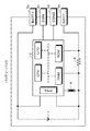
本開示の一実施の形態は、図1に示すように、二次電池の電池セル1と制御部2と関連する素子とが同一の筐体(ケース)内に収納されているバッテリパックに対して本開示を適用したものである。電池セル1は、例えばリチウムイオン二次電池である。電池セル1の規定充電電圧が例えば4.35Vに設定されている。<1. One embodiment>
"Battery pack"
One embodiment of the present disclosure is directed to a battery pack in which battery cells 1 of secondary batteries and elements related to
バッテリパックには、外部との接続用のコネクタ3a、3b、3cおよび3dが設けられている。コネクタ3aと電池セル1の正極とが接続され、コネクタ3bが電池セル1の負極とが接続される。コネクタ3cおよび3dは、制御部2と外部との通信用端子である。
The battery pack is provided with
バッテリパックを制御する制御部2は、例えばCPU(Central Processing Unit )、RAM(Random Access Memory)、ROM(Read Only Memory)、I/O(Input/Output)、AFE(Analog Front End)等で構成されるマイクロコンピュータである。AFEは、アナログ信号部と制御部2のCPUとの間に配されるアナログ回路である。なお、バッテリパック内に充電電流をオン/オフするスイッチング素子、並びに放電電流をオン/オフするスイッチング素子を設けて、これらのスイッチング素子を制御部2によって制御するようにしても良い。
The
制御部2には、電池セル1の電圧が供給される。さらに、バッテリパック内の温度が温度検出素子例えばサーミスタ4によって測定され、測定された温度情報が制御部2に供給される。さらに、電池セル1の電流経路を流れる電流が電流検出抵抗5によって検出され、検出された電流値が制御部2に供給される。
The
「充電制御」
制御部2によって電池セル1に対する充電動作が制御される。制御部2によってなされる制御は、図2のフローチャートで示される。なお、充電時には、充電装置の正負の出力端子とバッテリパックのコネクタ3a、3bとが接続され、充電装置の通信端子とコネクタ3c、3dとが接続される。充電装置は、一例として商用電源から所定の値の充電電圧と充電電流とを生成するものであり、バッテリパックの制御部2との通信によって、充電電圧および充電電流が設定される。通信方式としては、例えばシリアル通信が使用される。"Charge control"
The
本開示の一実施の形態では、電池セル1の公称容量を超えた電流値を充電電流として設定するようになされる。その結果、急速充電が行われる。加えて、サイクル特性の劣化を抑えるために、電池セル1の測定データに応じて充電パラメータを変化させる。測定データは、サイクル数、総動作時間、高電圧放置時間、高温放置時間、充放電時間、容量値、電池セルの内部インピーダンス等である。これら測定データは、電池セルの劣化に関係するデータであり、例えば制御部2内の不揮発性メモリに測定データが記憶されている。
In one embodiment of the present disclosure, a current value exceeding the nominal capacity of the battery cell 1 is set as the charging current. As a result, quick charging is performed. In addition, the charge parameters are changed according to the measurement data of the battery cell 1 in order to suppress the deterioration of the cycle characteristics. The measurement data includes the number of cycles, the total operation time, the high voltage leaving time, the high temperature leaving time, the charge and discharge time, the capacity value, the internal impedance of the battery cell and the like. These measurement data are data related to the deterioration of the battery cell, and for example, the measurement data is stored in the non-volatile memory in the
図2のフローチャートを参照して充電制御について説明する。
ステップST1:充電が開始される。
ステップST2:電池セル1の電圧(電池電圧)が測定される。例えば2秒間測定され、その平均値が使用される。
ステップST3:測定電圧が所定の電圧例えば4.1V以上であるか、またはバッテリパックの温度が常温領域外であるか否かが調べられる。ステップST3は、満充電付近まで充電されているかどうかの判定と、急速充電を行うのに適した温度環境であるかどうかの判定とを行うものである。The charge control will be described with reference to the flowchart of FIG.
Step ST1: Charging is started.
Step ST2: The voltage (battery voltage) of the battery cell 1 is measured. For example, it is measured for 2 seconds, and the average value is used.
Step ST3: It is checked whether the measured voltage is a predetermined voltage, for example, 4.1 V or more, or whether the temperature of the battery pack is outside the normal temperature range. In step ST3, it is determined whether or not the battery has been charged up to near full charge, and whether or not it is a temperature environment suitable for performing rapid charging.
測定電圧が4.1V以上であれば、満充電に近いので、本開示の急速充電を行う必要性が低いので、ステップST4以降の通常充電が行われる。通常充電は、定電流定電圧充電である。すなわち、定電流定電圧充電は、所定電圧まで定電流で充電を行い、所定電圧に電池電圧が達すると、定電圧で充電する方法である。定電流充電から定電圧充電に切り換わる電圧値は、例えば4.24Vである。さらに、バッテリパックの温度が常温領域外の場合には、より温度を上昇させることを防ぐために、急速充電がなされない。 If the measured voltage is 4.1 V or more, since it is close to full charge, the necessity of performing the rapid charge of the present disclosure is low, so that the normal charge after step ST4 is performed. Normal charging is constant current constant voltage charging. That is, constant current constant voltage charging is a method of charging with a constant current to a predetermined voltage and charging with a constant voltage when the battery voltage reaches a predetermined voltage. The voltage value for switching from constant current charging to constant voltage charging is, for example, 4.24V. Furthermore, if the temperature of the battery pack is outside the normal temperature range, rapid charging is not performed to prevent the temperature from rising further.
ステップST4:測定データ例えばサイクル数が設定値以下かどうかが判定される。ステップST4は、電池セル1の劣化の程度を判定するものである。
ステップST5:ステップST4の判定結果が肯定の場合では、充電電圧が電池セル1の規定充電電圧(例えば4.35V)に設定される。
ステップST6:定電流定電圧充電が行われる。例えば規定の充電電圧として4.35Vが使用され、充電電流が0.7ItAに設定される。なお、電流ItAは、(ItA=定格容量(Ah)/1(h))と定義され、1Cと等しい値である。Step ST4: It is determined whether measured data, for example, the number of cycles is equal to or less than a set value. Step ST4 determines the degree of deterioration of the battery cell 1.
Step ST5: If the determination result of step ST4 is affirmative, the charge voltage is set to the specified charge voltage (for example, 4.35 V) of the battery cell 1.
Step ST6: Constant current constant voltage charging is performed. For example, 4.35 V is used as the specified charging voltage, and the charging current is set to 0.7 ItA. The current ItA is defined as (ItA = rated capacity (Ah) / 1 (h)) and is equal to 1C.
ステップST7:満充電条件が成立するかどうかが判定される。満充電条件としては、従来の方法を使用できる。例えば充電電流が所定値(例えば公称容量の1/20以下の値)となることを満充電として検出するようになれる。なお、電池セル1の電圧と充電電圧との差が所定値以下となることを満充電として検出しても良い。満充電条件が成立しない場合には、ステップST6(定電流定電圧充電)に処理が戻る。
ステップST8:満充電条件が成立することによって満充電が検出される。
ステップST9:そして、充電動作が終了する。Step ST7: It is determined whether the full charge condition is satisfied. A conventional method can be used as the full charge condition. For example, it can be detected as a full charge that the charging current becomes a predetermined value (for example, a value of 1/20 or less of the nominal capacity). The fact that the difference between the voltage of the battery cell 1 and the charge voltage is equal to or less than a predetermined value may be detected as full charge. If the full charge condition is not satisfied, the process returns to step ST6 (constant current constant voltage charging).
Step ST8: A full charge is detected when the full charge condition is satisfied.
Step ST9: Then, the charging operation ends.
ステップST10:ステップST4において、測定データが設定値以下でないと判定されると、測定データに合わせて充電電圧が設定される。例えば充電電圧が規定充電電圧より小さい値に設定される。そして、ステップST6の定電流定電圧充電がなされる。以降の処理は、上述したのと同様である。 Step ST10: In step ST4, when it is determined that the measurement data is not less than the set value, the charging voltage is set in accordance with the measurement data. For example, the charging voltage is set to a value smaller than the specified charging voltage. Then, constant current constant voltage charging in step ST6 is performed. The subsequent processing is the same as described above.
上述したステップST3の判定結果が否定の場合、すなわち、測定電圧が4.1Vより小であり、且つバッテリパックの温度が常温領域内である場合には、ステップST11に処理が移り、ステップST11以降の処理によって急速充電が行われる。 If the result of the determination in step ST3 described above is negative, that is, if the measured voltage is smaller than 4.1 V and the temperature of the battery pack is within the normal temperature range, the process proceeds to step ST11, and after step ST11 The rapid charging is performed by the processing of
ステップST11:コネクタ3a、3bに供給される充電電圧を規定充電電圧以上の電圧例えば+5.0Vに上昇させると共に、充電電流を急速充電用の値に設定する。充電電圧を上げる理由は、電池セル1の内部抵抗や電子回路による抵抗によって生じる電圧上昇を考慮して、大電流充電時の充電電流の垂下を抑制させるためである。また、充電電流を急速充電に合わせた大きい電流値に設定することで、充電時間の短縮を狙う。急速充電に合わせた電流値は、電池セル1の公称容量を超えた電流値であり、例えば1.8ItAに設定される。例えば1.8ItA=5274mAとされる。
ステップST12:設定された充電電圧および充電電流によって急速充電を行う。Step ST11: The charging voltage supplied to the
Step ST12: Perform rapid charging with the set charging voltage and charging current.
ステップST13:急速充電中に、測定した電池電圧が閾値電圧Aより大となるかどうかが判定されてる。電池電圧が閾値電圧A以下の場合には、充電電圧および充電電流を変更しないでステップST12の急速充電が続行される。閾値電圧Aは、規定充電電圧以下の値の電圧である。一例として、閾値電圧Aの初期値が4.24Vに設定される。
ステップST14:ステップST13の判定結果が肯定の場合、すなわち、電池電圧が閾値電圧Aより大と判定されると、充電電流が所定量例えば0.1ItA低下させると共に閾値電圧Aを所定量10mV上昇させる処理がなされる。Step ST13: During rapid charging, it is determined whether the measured battery voltage is higher than the threshold voltage A. If the battery voltage is equal to or lower than the threshold voltage A, the rapid charging in step ST12 is continued without changing the charging voltage and the charging current. The threshold voltage A is a voltage having a value less than or equal to the specified charging voltage. As an example, the initial value of threshold voltage A is set to 4.24V.
Step ST14: If the determination result in step ST13 is affirmative, that is, if the battery voltage is determined to be larger than the threshold voltage A, the charging current is decreased by a predetermined amount, for example, 0.1 ItA and the threshold voltage A is increased by a
ステップST15:(充電電流<所定値)で且つ(測定電圧≧所定値)の関係が成立するかどうかが判定される。例えば(充電電流<0.71ItA)で且つ(測定電圧≧充電電圧)の関係とされる。この条件が成立すると、満充電付近であると判定し、充電電圧を5.0Vから規格充電電圧へと下げる。そして、処理がステップST4(測定データが設定値以下かどうかの判定)に戻る。ステップST4以降、満充電まで定電流定電圧充電が行われる。 Step ST15: It is determined whether the relationship of (charging current <predetermined value) and (measured voltage 所 定 predetermined value) is established. For example, (charging current <0.71 ItA) and (measured voltage 充電 charging voltage) have a relationship. When this condition is satisfied, it is determined that the battery is near full charge, and the charge voltage is reduced from 5.0 V to the standard charge voltage. Then, the process returns to step ST4 (determination of whether the measurement data is equal to or less than the set value). From step ST4, constant current constant voltage charging is performed until full charging.
このように急速充電時では、制御された充電電圧および充電電流による定電流充電がなされる、二次電池の測定電圧が閾値電圧A(電池セル1の規定充電電圧以下)に達する度に、充電電流が例えば0.1ItAずつ逐次低減される。充電電流が1段階下がったことで、測定電圧も閾値電圧Aより小さくなり、次に、測定電圧が10mV上昇された閾値電圧Aよりも大となると、充電電流が0.1ItA下げられる。このように充電電流を逐次低減させながら段階的に充電を行うと、閾値電圧Aへの到達と電圧降下が繰り返される。かかる制御によって、大電流による充電にもかかわらず、充電中に電池セル1の規定充電電圧に近い状態にある時間を短く抑えることができ、サイクル経過による容量の劣化に対する影響を小さくすることができる。 Thus, during rapid charging, constant current charging is performed with controlled charging voltage and charging current, and charging is performed every time the measured voltage of the secondary battery reaches threshold voltage A (less than the specified charging voltage of battery cell 1). The current is successively reduced by, for example, 0.1 ItA. By charging current has dropped by one step, the measured voltage becomes smaller than the threshold voltage A, then, when the measured voltage is larger than the threshold voltage A which is increased 10 mV, the charge current is reduced 0.1 ItA. When charging is performed stepwise while the charging current is sequentially reduced in this manner, reaching the threshold voltage A and voltage drop are repeated. By such control, it is possible to suppress the time in the state close to the specified charge voltage of the battery cell 1 during charging in spite of the large current charging, and to reduce the influence on the deterioration of the capacity by the cycle progress. .
「充電制御のグラフ」
図3は、本開示の一実施の形態の充電制御を示すグラフである。図3の横軸が時間経過を示し、縦軸が電圧(mV)または電流(mA)とSOC(%)とを示す。このグラフでは、時刻Tにおいて、急速充電から定電流定電圧充電に切り換わっている。なお、急速充電から定電流定電圧充電に切り換えずに、満充電まで急速充電を行うようにしても良い。本開示の一実施の形態のように、急速充電から定電流定電圧充電に切り換えるのは、充電電流を次第に小とする本開示の場合では、急速充電のみでは、充電にかかる時間が長くなる可能性があるためである。"Graph of charge control"
FIG. 3 is a graph showing charge control according to an embodiment of the present disclosure. The horizontal axis in FIG. 3 indicates time lapse, and the vertical axis indicates voltage (mV) or current (mA) and SOC (%). In this graph, at time T, fast charging is switched to constant current constant voltage charging. The fast charge may be performed until the full charge without switching from the quick charge to the constant current constant voltage charge. As in the embodiment of the present disclosure, switching from rapid charging to constant current constant voltage charging may increase the time required for charging with rapid charging alone in the case of the present disclosure in which the charging current is gradually reduced. It is because there is sex.
さらに、図4は、時刻Tまでの充電電圧、充電電流、電池電圧のそれぞれを拡大して示すグラフであり、一方の縦軸が電圧(mV)を示し、他方の縦軸が電流(mA)を示す。図4には、規定充電電圧4350(mV)(1点鎖線)および最初の閾値電圧4240(mV)(1点鎖線)がそれぞれ示されている。 Furthermore, FIG. 4 is a graph showing each of the charging voltage, the charging current, and the battery voltage up to time T in an enlarged manner, one vertical axis indicates voltage (mV) and the other vertical axis indicates current (mA). Indicates In FIG. 4, a specified charging voltage 4350 (mV) (one-dot chain line) and an initial threshold voltage 4240 (mV) (one-dot chain line) are respectively shown.
最初は、充電電圧が5000(mV)(参照符号11)に設定されると共に、充電電流が5274(mA)(参照符号12)に設定される。電池電圧が急速に上昇し、閾値電圧を超えると、充電電流が0.1ItA(例えば293(mA))減少される。充電電流が減少されると、電池電圧が一旦小さくなる。そして、再び電圧が上昇して、次の閾値電圧(4240(mV)+10(mV)=4250(mV))を電圧が超えると、充電電流が0.1ItA減少される。 Initially, the charge voltage is set to 5000 (mV) (reference numeral 11) and the charge current is set to 5274 (mA) (reference numeral 12). When the battery voltage rises rapidly and exceeds the threshold voltage, the charge current is reduced by 0.1 ItA (eg, 293 (mA)). When the charging current is reduced, the battery voltage is once reduced. When the voltage rises again and exceeds the next threshold voltage (4240 (mV) +10 (mV) = 4250 (mV)), the charge current is decreased by 0.1 ItA.
そして、充電電流が0.7ItA(2051(mA))を超え、且つ電圧が規定充電電圧(4350(mV))を超える時刻Tで急速充電から定電流定電圧充電に切り換わる。なお、充電電流および電流は、時刻Tまでは、同様に変化し、時刻T以降は、充電電流が一定であるのに対して、電流が一旦上昇した後は、徐々に小さくなる。 Then, at time T when the charging current exceeds 0.7 ItA (2051 (mA)) and the voltage exceeds the specified charging voltage (4350 (mV)), the fast charging switches to the constant current constant voltage charging. The charging current and the current change similarly until time T, and after time T, the charging current is constant, but gradually decreases after the current once rises.
充電が進むにしたがって、SOC(参照符号14)が上昇する。図3および図4に示すように、充電開始から15分で約41%、30分で約71%、60分時点で約93%まで充電することが可能である。 As charging progresses, the SOC (reference numeral 14) rises. As shown in FIGS. 3 and 4, it is possible to charge approximately 41% in 15 minutes, approximately 71% in 30 minutes, and approximately 93% in 60 minutes from the start of charging.
上述した本開示の一実施の形態においては、充電電流が1.8ItAから0.1ItAのステップでもって段階的に0.7ItAまで減少される。この関係から充電電流が減少するステップ数が求められる。すなわち、(1.8−0.7)/0.1=11(ステップ)である。さらに、最初の電圧変化は、(4350(mV)−4240(mV)=110(mV))であるので、110(mV)/11=10(mV)となる。したがって、閾値電圧を上昇させる単位が10(mV)と設定されている。 In one embodiment of the present disclosure described above, the charge current is reduced stepwise to 0.7 ItA in steps of 1.8 ItA to 0.1 ItA. From this relationship, the number of steps in which the charging current decreases can be obtained. That is, (1.8−0.7) /0.1=11 (step). Furthermore, since the first voltage change is (4350 (mV)-4240 (mV) = 110 (mV)), it will be 110 (mV) / 11 = 10 (mV). Therefore, the unit for increasing the threshold voltage is set to 10 (mV).
「本開示の効果」
図4のグラフから分かるように、本開示の一実施の形態では、大電流で充電される期間において、閾値電圧が規定充電電圧(4350(mV))より小さい範囲に設定されている。本開示の発明者の実験等によると、サイクル経過による容量劣化には、二次電池の高電圧時間の他、高電圧状態での大電流による充電も関係があることが判明した。そのため、充電電流を逐次低減させていく制御では、初回の大電流充電時は閾値電圧Aを低く設定しておき、充電電流の低下に伴って閾値電圧Aを逐次上げていく制御を行なっている。この制御により、目標である急速充電と容量劣化の抑制を両立させている。"Effect of this disclosure"
As can be seen from the graph of FIG. 4, in one embodiment of the present disclosure, the threshold voltage is set to a range smaller than the specified charging voltage (4350 (mV)) during the period of charging with a large current. According to experiments etc. by the inventor of the present disclosure, it has been found that the capacity deterioration due to the cycle progress is related to charging by a large current in a high voltage state as well as the high voltage time of the secondary battery. Therefore, in the control for reducing the charging current successively, the threshold voltage A is set low at the time of the first large current charging, and the control for sequentially raising the threshold voltage A with the decrease of the charging current is performed. . By this control, the target rapid charging and suppression of capacity deterioration are made compatible.
図5は、サイクル特性を示している。充電電流を低減させる際の閾値電圧Aを二次電池の規定充電電圧に設定した場合のサイクル特性21と、規定充電電圧よりも低い値に設定した場合のサイクル特性22とを比較すると分かるように、サイクル経過による容量の差が大きく生じる。規定充電電圧を検出してから充電電流を低減させる方法では、規定充電電圧に近い状態の時間が長くなってしまうため、放電容量の低下が大きくなる問題が生じる。 FIG. 5 shows cycle characteristics. As can be seen by comparing the cycle characteristic 21 when the threshold voltage A at the time of reducing the charging current is set to the specified charging voltage of the secondary battery and the cycle characteristic 22 when it is set to a value lower than the specified charging voltage. There is a large difference in capacity with the passage of cycles. In the method of reducing the charging current after detecting the specified charging voltage, the time in a state close to the specified charging voltage is long, and thus there is a problem that the decrease in the discharge capacity becomes large.
<2.変形例>
二次電圧の様々な測定データ(サイクル数、総動作時間、高電圧放置時間、高温放置時間、充放電時間、容量値、インピーダンス等)を参照して、測定データの値が設定した値以上になったと判定される場合、容量劣化が進んでいると判断して、充電パラメータを可変する。<2. Modified example>
With reference to various measurement data of secondary voltage (cycle number, total operation time, high voltage leaving time, high temperature leaving time, charge / discharge time, capacity value, impedance etc.), the value of the measurement data exceeds the set value If it is determined that the battery capacity has not reached, it is determined that the capacity deterioration has progressed, and the charge parameter is varied.
可変させる充電パラメータは、例えば急速充電で充電電流が公称容量の0.7ItAまで低減した際の充電電圧および閾値電圧Aを、二次電池の規定充電電圧から10(mV)下げた値にそれぞれ設定する。また、サイクル経過による内部抵抗の上昇も考慮して、急速充電用に設定している充電開始時の電流値も0.1ItA下げた値に設定する。この制御では複数の設定値を段階的に用意しておき、例えばサイクル数が一定値増加する毎に段階的に充電電圧、閾値電圧A、充電電流を下げることができる。このような充電パラメータを可変する制御によって、より長期的な劣化を抑制することが可能である。 The charge parameters to be varied are set, for example, to a value obtained by lowering the charge voltage and the threshold voltage A when the charge current is reduced to 0.7 ItA of the nominal capacity in rapid charge by 10 (mV) lower than the specified charge voltage of the secondary battery. Do. In addition, the current value at the start of charging, which is set for rapid charging, is also set to a value reduced by 0.1 ItA, in consideration of the increase in internal resistance due to the passage of cycles. In this control, a plurality of setting values are prepared in stages, and for example, the charging voltage, the threshold voltage A, and the charging current can be lowered stepwise each time the number of cycles increases by a fixed value. It is possible to suppress long-term deterioration by controlling such variable charging parameters.
図6に示すグラフは、二次電池のサイクル数に応じて急速充電後の定電流定電圧充電での充電電圧および急速充電から移行する際の閾値電圧Aを10(mV)ずつ下げる制御を導入した二次電池と、規定充電電圧まで充電させた二次電池のサイクル試験の結果である。サイクルが進むたびに充電電圧が10(mV)ずつ低下していくので、短期的に見れば制御ありの二次電池の方が容量低下している。しかしながら、充電中の電圧が規定充電電圧を超えることがなくなるので、長期的に見れば規定充電電圧まで充電した二次電池よりも容量低下を抑えることができる。 The graph shown in FIG. 6 introduces a control to lower the charge voltage in constant current constant voltage charge after rapid charge and the threshold voltage A at the time of transition from rapid charge by 10 (mV) according to the number of cycles of the secondary battery. It is the result of the cycle test of the secondary battery and the secondary battery charged to the specified charging voltage. Since the charge voltage decreases by 10 (mV) each time the cycle progresses, the capacity of the secondary battery with control decreases in a short term. However, since the voltage during charging does not exceed the specified charging voltage, in the long run, the capacity reduction can be suppressed more than that of the secondary battery charged to the specified charging voltage.
二次電圧の容量低下には環境温度も大きく影響するため、本開示の急速充電制御において、充電開始時に測定した二次電池の温度が常温領域の場合のみ動作する、としても良い。さらに、環境温度が低温領域か、高温領域かに応じて充電電流および/または充電電圧を変更するとしても良い。 Since the environmental temperature also greatly affects the capacity reduction of the secondary voltage, in the rapid charge control of the present disclosure, it may be operated only when the temperature of the secondary battery measured at the start of charging is in the normal temperature region. Furthermore, the charging current and / or the charging voltage may be changed depending on whether the environmental temperature is in a low temperature region or a high temperature region.
上述した一実施の形態は、本開示をバッテリパックに対して適用した例である。しかしながら、図7に示すように、電子機器の側で充電を制御するようにしても良い。バッテリパック41には、電池セル1およびサーミスタ4が設けられている。電子機器42が制御部43および電流検出抵抗44を備えている。AC/DC変換装置45により形成される直流電源が充電電源として使用される。電子機器42の制御部43が上述した一実施の形態の制御部2と同様の制御(図2のフローチャート参照)を行う。かかる構成によっても同様の効果が得られる。
The above-described embodiment is an example in which the present disclosure is applied to a battery pack. However, as shown in FIG. 7, the charge may be controlled on the electronic device side. The
図8に示すように、バッテリパック41を充電する充電装置51側で制御する構成も可能である。充電装置51は、制御部53および電流検出抵抗54を備えており、充電装置51の制御部53が上述した一実施の形態の制御部2と同様の制御(図2のフローチャート参照)を行う。かかる構成によっても同様の効果が得られる。
As shown in FIG. 8, a configuration in which control is performed on the side of the charging
上述した一実施の形態は、本開示を一つの電池セル1を有するバッテリパックに対して適用した例である。しかしながら、図9に示すように、複数例えば4個の電池セル1a、1b、1c、1dが直列接続された電池を有するバッテリパックに対しても、本開示を同様に適用でき、同様の効果が得られる。
The above-described embodiment is an example in which the present disclosure is applied to a battery pack having one battery cell 1. However, as shown in FIG. 9, the present disclosure can be similarly applied to a battery pack having a battery in which a plurality of, for example, four
「変形例」
以上、本開示の実施形態について具体的に説明したが、上述の各実施形態に限定されるものではなく、本開示の技術的思想に基づく各種の変形が可能である。例えば、上述の実施形態において挙げた構成、方法、工程、形状、材料および数値などはあくまでも例に過ぎず、必要に応じてこれと異なる構成、方法、工程、形状、材料および数値などを用いても良い。"Modification"
As mentioned above, although embodiment of this indication was described concretely, it is not limited to each above-mentioned embodiment, and various modification based on the technical idea of this indication are possible. For example, the configurations, methods, processes, shapes, materials, numerical values, and the like described in the above embodiments are merely examples, and different configurations, methods, processes, shapes, materials, numerical values, and the like may be used as necessary. Also good.
また、上述の実施形態の構成、方法、工程、形状、材料および数値などは、本開示の主旨を逸脱しない限り、互いに組み合わせることが可能である。 Furthermore, the configurations, methods, processes, shapes, materials, numerical values, and the like of the above-described embodiments can be combined with one another without departing from the spirit of the present disclosure.
1,1a〜1d 電池セル
2,43,53 制御部
5,44,54 電流検出抵抗1, 1a to
Claims (5)
前記二次電池の電圧、電流および温度を測定する測定部と、
前記測定部からの測定電圧、測定電流および測定温度が供給され、前記二次電池の充電電圧および充電電流を制御する制御部とを有し、
前記制御部は、
前記測定電圧が所定の電圧より大きいか、または、前記測定温度が常温領域外のとき、定電流定電圧充電を行うように前記充電電圧および前記充電電流を制御し、
前記測定電圧が所定の電圧より小さく、且つ、前記測定温度が常温領域内のときに、急速充電を行うように前記充電電圧および前記充電電流を制御し、
前記急速充電においては、その公称容量を超えた電流値を第1の充電電流に設定し、
設定した第1の充電電流による定電流充電を行いながら、前記二次電池の測定電圧を、定電流定電圧充電においてサイクル数が設定値以下の場合の充電電圧である規定充電電圧より小の第1の閾値電圧と比較し、
前記測定電圧が前記第1の閾値電圧より大となると、前記第1の充電電流を所定量減少させて第2の充電電流にすると共に、前記第1の閾値電圧を所定量上昇させて第2の閾値電圧とし、
設定した第2の充電電流による定電流充電を行いながら、前記二次電池の測定電圧を前記規定充電電圧より小の前記第2の閾値電圧と比較し、
前記測定電圧が前記第2の閾値電圧より大となると、前記第2の充電電流を所定量減少させて第3の充電電流にすると共に、前記第2の閾値電圧を所定量上昇させて第3の閾値電圧とし、
前記測定電圧と閾値電圧との比較と、前記充電電流の減少および閾値電圧の所定量上昇とを繰り返し、第nの充電電流が所定電流まで低下し、且つ前記測定電圧が所定電圧より大となる場合に、前記急速充電を終了して定電流定電圧充電に切り換える制御を行い、
前記二次電池のサイクル数に応じて定電流定電圧充電時の充電電圧及び前記所定電圧を下げることを特徴とする
電池装置。 With a secondary battery,
A measurement unit that measures voltage, current, and temperature of the secondary battery;
A control unit that is supplied with the measurement voltage, the measurement current, and the measurement temperature from the measurement unit, and controls the charging voltage and the charging current of the secondary battery;
The control unit
The charging voltage and the charging current are controlled to perform constant current constant voltage charging when the measured voltage is higher than a predetermined voltage or when the measured temperature is outside a normal temperature range,
Controlling the charging voltage and the charging current so as to perform rapid charging when the measured voltage is smaller than a predetermined voltage and the measured temperature is in a normal temperature region;
In the quick charge, a current value exceeding its nominal capacity is set as a first charge current,
While performing constant current charging with the set first charging current, the measurement voltage of the secondary battery is set to a first value smaller than a specified charging voltage which is a charging voltage when the number of cycles is less than a set value in constant current constant voltage charging . Compared to a threshold voltage of 1,
When the measured voltage becomes larger than the first threshold voltage, the first charging current is decreased by a predetermined amount to be a second charging current, and the first threshold voltage is increased by a predetermined amount, and the second charging current is increased. Threshold voltage of
While the constant current charging of the second charging current set, compared to the secondary second threshold voltage measured voltage of less than the prescribed charging voltage of the battery,
When the measured voltage becomes larger than the second threshold voltage, the second charging current is decreased by a predetermined amount to be a third charging current, and the second threshold voltage is increased by a predetermined amount, and the third charging current is increased. Threshold voltage of
The comparison between the measured voltage and the threshold voltage, and the decrease of the charge current and the increase of the predetermined amount of the threshold voltage are repeated, and the nth charge current decreases to a predetermined current , and the measured voltage becomes larger than the predetermined voltage. Control to end the rapid charging and switch to constant current constant voltage charging,
A battery device characterized by lowering a charging voltage at the time of constant current constant voltage charging and the predetermined voltage according to the number of cycles of the secondary battery.
前記測定電圧が所定の電圧より大きいか、または、前記測定温度が常温領域外のとき、定電流定電圧充電を行うように前記充電電圧および前記充電電流を制御し、
前記測定電圧が所定の電圧より小さく、且つ、前記測定温度が常温領域内のときに、急速充電を行うように前記充電電圧および前記充電電流を制御し、
前記急速充電においては、その公称容量を超えた電流値を第1の充電電流に設定し、
設定した第1の充電電流による定電流充電を行いながら、前記二次電池の測定電圧を、定電流定電圧充電においてサイクル数が設定値以下の場合の充電電圧である規定充電電圧より小の第1の閾値電圧と比較し、
前記測定電圧が前記第1の閾値電圧より大となると、前記第1の充電電流を所定量減少させて第2の充電電流にすると共に、前記第1の閾値電圧を所定量上昇させて第2の閾値電圧とし、
設定した第2の充電電流による定電流充電を行いながら、前記二次電池の測定電圧を前記規定充電電圧より小の前記第2の閾値電圧と比較し、
前記測定電圧が前記第2の閾値電圧より大となると、前記第2の充電電流を所定量減少させて第3の充電電流にすると共に、前記第2の閾値電圧を所定量上昇させて第3の閾値電圧とし、
前記測定電圧と閾値電圧との比較と、前記充電電流の減少および閾値電圧の所定量上昇とを繰り返し、第nの充電電流が所定電流まで低下し、且つ前記測定電圧が所定電圧より大となる場合に、前記急速充電を終了して定電流定電圧充電に切り換える制御を行い、
前記二次電池のサイクル数に応じて定電流定電圧充電時の充電電圧及び前記所定電圧を下げることを特徴とする
充電制御装置。 A charge control device which is supplied with a measurement voltage, a measurement current and a measurement temperature of a secondary battery to be charged, and controls a charging voltage and a charging current of the secondary battery,
The charging voltage and the charging current are controlled to perform constant current constant voltage charging when the measured voltage is higher than a predetermined voltage or when the measured temperature is outside a normal temperature range,
Controlling the charging voltage and the charging current so as to perform rapid charging when the measured voltage is smaller than a predetermined voltage and the measured temperature is in a normal temperature region;
In the quick charge, a current value exceeding its nominal capacity is set as a first charge current,
While performing constant current charging with the set first charging current, the measurement voltage of the secondary battery is set to a first value smaller than a specified charging voltage which is a charging voltage when the number of cycles is less than a set value in constant current constant voltage charging . Compared to a threshold voltage of 1,
When the measured voltage becomes larger than the first threshold voltage, the first charging current is decreased by a predetermined amount to be a second charging current, and the first threshold voltage is increased by a predetermined amount, and the second charging current is increased. Threshold voltage of
While the constant current charging of the second charging current set, compared to the secondary second threshold voltage measured voltage of less than the prescribed charging voltage of the battery,
When the measured voltage becomes larger than the second threshold voltage, the second charging current is decreased by a predetermined amount to be a third charging current, and the second threshold voltage is increased by a predetermined amount, and the third charging current is increased. Threshold voltage of
The comparison between the measured voltage and the threshold voltage, and the decrease of the charge current and the increase of the predetermined amount of the threshold voltage are repeated, and the nth charge current decreases to a predetermined current , and the measured voltage becomes larger than the predetermined voltage. Control to end the rapid charging and switch to constant current constant voltage charging,
A charge control device characterized by lowering a charging voltage at the time of constant current constant voltage charging and the predetermined voltage according to the number of cycles of the secondary battery.
前記測定電圧が所定の電圧より大きいか、または、前記測定温度が常温領域外のとき、定電流定電圧充電を行うように前記充電電圧および前記充電電流を制御し、
前記測定電圧が所定の電圧より小さく、且つ、前記測定温度が常温領域内のときに、急速充電を行うように前記充電電圧および前記充電電流を制御し、
前記急速充電においては、その公称容量を超えた電流値を第1の充電電流に設定し、
設定した第1の充電電流による定電流充電を行いながら、前記二次電池の測定電圧を、定電流定電圧充電においてサイクル数が設定値以下の場合の充電電圧である規定充電電圧より小の第1の閾値電圧と比較し、
前記測定電圧が前記第1の閾値電圧より大となると、前記第1の充電電流を所定量減少させて第2の充電電流にすると共に、前記第1の閾値電圧を所定量上昇させて第2の閾値電圧とし、
設定した第2の充電電流による定電流充電を行いながら、前記二次電池の測定電圧を前記規定充電電圧より小の前記第2の閾値電圧と比較し、
前記測定電圧が前記第2の閾値電圧より大となると、前記第2の充電電流を所定量減少させて第3の充電電流にすると共に、前記第2の閾値電圧を所定量上昇させて第3の閾値電圧とし、
前記測定電圧と閾値電圧との比較と、前記充電電流の減少および閾値電圧の所定量上昇とを繰り返し、第nの充電電流が所定電流まで低下し、且つ前記測定電圧が所定電圧より大となる場合に、前記急速充電を終了して定電流定電圧充電に切り換える制御を行い、
前記二次電池のサイクル数に応じて定電流定電圧充電時の充電電圧及び前記所定電圧を下げることを特徴とする
充電制御方法。 A charge control method for receiving a measured voltage, a measured current and a measured temperature of a secondary battery to be charged, and controlling a charge voltage and a charge current of the secondary battery,
The charging voltage and the charging current are controlled to perform constant current constant voltage charging when the measured voltage is higher than a predetermined voltage or when the measured temperature is outside a normal temperature range,
Controlling the charging voltage and the charging current so as to perform rapid charging when the measured voltage is smaller than a predetermined voltage and the measured temperature is in a normal temperature region;
In the quick charge, a current value exceeding its nominal capacity is set as a first charge current,
While performing constant current charging with the set first charging current, the measurement voltage of the secondary battery is set to a first value smaller than a specified charging voltage which is a charging voltage when the number of cycles is less than a set value in constant current constant voltage charging . Compared to a threshold voltage of 1,
When the measured voltage becomes larger than the first threshold voltage, the first charging current is decreased by a predetermined amount to be a second charging current, and the first threshold voltage is increased by a predetermined amount, and the second charging current is increased. Threshold voltage of
While the constant current charging of the second charging current set, compared to the secondary second threshold voltage measured voltage of less than the prescribed charging voltage of the battery,
When the measured voltage becomes larger than the second threshold voltage, the second charging current is decreased by a predetermined amount to be a third charging current, and the second threshold voltage is increased by a predetermined amount, and the third charging current is increased. Threshold voltage of
The comparison between the measured voltage and the threshold voltage, and the decrease of the charge current and the increase of the predetermined amount of the threshold voltage are repeated, and the nth charge current decreases to a predetermined current , and the measured voltage becomes larger than the predetermined voltage. Control to end the rapid charging and switch to constant current constant voltage charging,
A charge control method comprising: reducing a charging voltage at the time of constant current constant voltage charging and the predetermined voltage according to the number of cycles of the secondary battery.
Applications Claiming Priority (3)
| Application Number | Priority Date | Filing Date | Title |
|---|---|---|---|
| JP2015007214 | 2015-01-16 | ||
| JP2015007214 | 2015-01-16 | ||
| PCT/JP2015/005989 WO2016113791A1 (en) | 2015-01-16 | 2015-12-02 | Cell device, charging control device, and charging control method |
Publications (2)
| Publication Number | Publication Date |
|---|---|
| JPWO2016113791A1 JPWO2016113791A1 (en) | 2017-10-19 |
| JP6500911B2 true JP6500911B2 (en) | 2019-04-17 |
Family
ID=56405361
Family Applications (1)
| Application Number | Title | Priority Date | Filing Date |
|---|---|---|---|
| JP2016569128A Active JP6500911B2 (en) | 2015-01-16 | 2015-12-02 | Battery device, charge control device and charge control method |
Country Status (3)
| Country | Link |
|---|---|
| US (1) | US10553913B2 (en) |
| JP (1) | JP6500911B2 (en) |
| WO (1) | WO2016113791A1 (en) |
Families Citing this family (17)
| Publication number | Priority date | Publication date | Assignee | Title |
|---|---|---|---|---|
| EP3288150B1 (en) * | 2015-08-06 | 2021-04-07 | Murata Manufacturing Co., Ltd. | Secondary battery charging method, charging control device, and secondary battery |
| JP6220904B2 (en) * | 2016-01-14 | 2017-10-25 | 本田技研工業株式会社 | Power storage device |
| JP5973106B1 (en) * | 2016-04-06 | 2016-08-23 | 本田技研工業株式会社 | Power supply apparatus, transport apparatus having the power supply apparatus, determination method for determining the state of a sensor that detects a current value, and program for determining the state |
| JP6348929B2 (en) * | 2016-05-23 | 2018-06-27 | 本田技研工業株式会社 | Power system, transport equipment, and power transmission method |
| CN107994622A (en) * | 2016-10-26 | 2018-05-04 | 宁德时代新能源科技股份有限公司 | Battery power supply circuit |
| US10291046B2 (en) * | 2016-11-23 | 2019-05-14 | Robert Bosch Gmbh | Method for fast charging lithium-ion batteries |
| TWI614966B (en) * | 2017-01-03 | 2018-02-11 | 飛宏科技股份有限公司 | Charging method on constant current mode |
| CN107204493B (en) * | 2017-04-28 | 2020-09-29 | 宁德时代新能源科技股份有限公司 | Battery charging method, device and equipment |
| JP6897765B2 (en) * | 2017-04-28 | 2021-07-07 | 株式会社Gsユアサ | Management device, power storage device and power storage system |
| KR102516361B1 (en) | 2017-12-07 | 2023-03-31 | 삼성전자주식회사 | Method and apparatus for charging battery |
| EP3641093B1 (en) | 2018-10-18 | 2020-12-02 | 3M Innovative Properties Company | A method of charging a battery and a system having a dental light irradiation device and a battery charging device |
| CN109738819A (en) * | 2018-12-10 | 2019-05-10 | 上海艾为电子技术股份有限公司 | Battery converts voltage computing system, method, battery and battery charger |
| JP7437605B2 (en) * | 2019-12-19 | 2024-02-26 | 株式会社Gsユアサ | Charging control device, power storage device, charging control method |
| KR20210097531A (en) | 2020-01-30 | 2021-08-09 | 삼성에스디아이 주식회사 | Method for charging battery |
| CN112039147A (en) * | 2020-08-20 | 2020-12-04 | Tcl通力电子(惠州)有限公司 | Charging method, charging device and computer readable storage medium |
| US20220089054A1 (en) * | 2020-09-18 | 2022-03-24 | Cummins Inc. | Estimation of charging duration for electric vehicles |
| US11565605B2 (en) * | 2020-10-29 | 2023-01-31 | Wing Aviation Llc | Systems and methods for battery capacity management in a fleet of UAVs |
Family Cites Families (16)
| Publication number | Priority date | Publication date | Assignee | Title |
|---|---|---|---|---|
| US3517293A (en) | 1967-01-31 | 1970-06-23 | Mcculloch Corp | Rapid charging of batteries |
| JPS5116326B2 (en) * | 1971-08-02 | 1976-05-24 | ||
| JP2599333B2 (en) * | 1992-10-07 | 1997-04-09 | 株式会社タムラ製作所 | Rechargeable battery charging method |
| JP3692547B2 (en) | 1994-04-22 | 2005-09-07 | ソニー株式会社 | Charging method |
| JPH1197074A (en) | 1997-09-19 | 1999-04-09 | Zip Charge:Kk | Charging method and charging device |
| JPH09331636A (en) * | 1996-06-11 | 1997-12-22 | Oki Electric Ind Co Ltd | Charger of secondary battery |
| JP4221636B2 (en) * | 2000-10-19 | 2009-02-12 | ソニー株式会社 | Lithium ion secondary battery charging method and charging device |
| JP4093205B2 (en) | 2003-12-05 | 2008-06-04 | 松下電器産業株式会社 | Charge control device |
| JP2008035674A (en) * | 2006-07-31 | 2008-02-14 | Mitsumi Electric Co Ltd | Charging power supply unit |
| JP2010207074A (en) * | 2009-02-09 | 2010-09-16 | Nec Corp | System, device and method for control of non-contact charge |
| US8643342B2 (en) * | 2009-12-31 | 2014-02-04 | Tesla Motors, Inc. | Fast charging with negative ramped current profile |
| JP5506498B2 (en) | 2010-03-30 | 2014-05-28 | パナソニック株式会社 | Secondary battery charging device and charging method |
| US8513919B2 (en) * | 2010-07-28 | 2013-08-20 | Apple Inc. | Swelling management in batteries for portable electronic devices |
| JP5774388B2 (en) | 2011-06-29 | 2015-09-09 | 三洋電機株式会社 | Secondary battery charging method, charging control device and battery pack |
| JP5816814B2 (en) | 2011-08-31 | 2015-11-18 | パナソニックIpマネジメント株式会社 | Charger |
| JP5879557B2 (en) | 2011-09-12 | 2016-03-08 | パナソニックIpマネジメント株式会社 | Charger |
-
2015
- 2015-12-02 WO PCT/JP2015/005989 patent/WO2016113791A1/en active Application Filing
- 2015-12-02 US US15/538,272 patent/US10553913B2/en active Active
- 2015-12-02 JP JP2016569128A patent/JP6500911B2/en active Active
Also Published As
| Publication number | Publication date |
|---|---|
| JPWO2016113791A1 (en) | 2017-10-19 |
| US20170352926A1 (en) | 2017-12-07 |
| WO2016113791A1 (en) | 2016-07-21 |
| US10553913B2 (en) | 2020-02-04 |
Similar Documents
| Publication | Publication Date | Title |
|---|---|---|
| JP6500911B2 (en) | Battery device, charge control device and charge control method | |
| JP5219485B2 (en) | Charging method | |
| JP4865103B2 (en) | Charging apparatus and charging method | |
| US8264198B2 (en) | Battery pack, battery charger and charging method having multiple charging modes | |
| US9627904B2 (en) | Charging method and charger | |
| JP5618986B2 (en) | Charger | |
| JP2020511737A (en) | Battery management system and method for optimizing internal resistance of battery | |
| KR101854557B1 (en) | System for determining a discharge power limit value and a charge power limit value of a battery cell | |
| JP6196466B2 (en) | Power supply | |
| JP2008206259A (en) | Charging system, charger, and battery pack | |
| KR101897555B1 (en) | A storage system, a storage control method, and a storage medium storing a storage control program | |
| JP2005269708A (en) | Battery device and method of controlling charge of battery device | |
| WO2015162877A1 (en) | Lithium ion secondary battery system and lithium secondary battery system operation method | |
| JP2015104139A (en) | Charging method of secondary battery, and charging device employing the same | |
| JP5949510B2 (en) | Charge control device and charge control method | |
| KR102349705B1 (en) | Battery cell balancing circuit and apparatus and method for balancing of a battery cell for using the same | |
| JP2007259632A (en) | Charging circuit and charging control method | |
| JP5953567B2 (en) | Power storage device and charging / discharging method thereof | |
| CN108572323B (en) | Battery state estimation device | |
| JP2020520624A (en) | Battery management system and method for optimizing internal resistance of battery | |
| CN109450016A (en) | Charging method, mobile power source and computer storage medium | |
| JPWO2015141003A1 (en) | Secondary battery charging system and secondary battery charging method | |
| JP2021090318A (en) | Battery pack, control method, and program | |
| US11424628B2 (en) | Balance charging method and charging device for charging multiple battery cells |
Legal Events
| Date | Code | Title | Description |
|---|---|---|---|
| A625 | Written request for application examination (by other person) |
Free format text: JAPANESE INTERMEDIATE CODE: A625 Effective date: 20171011 |
|
| A711 | Notification of change in applicant |
Free format text: JAPANESE INTERMEDIATE CODE: A712 Effective date: 20171011 |
|
| A711 | Notification of change in applicant |
Free format text: JAPANESE INTERMEDIATE CODE: A711 Effective date: 20171012 |
|
| A131 | Notification of reasons for refusal |
Free format text: JAPANESE INTERMEDIATE CODE: A131 Effective date: 20180522 |
|
| A521 | Request for written amendment filed |
Free format text: JAPANESE INTERMEDIATE CODE: A523 Effective date: 20180718 |
|
| A131 | Notification of reasons for refusal |
Free format text: JAPANESE INTERMEDIATE CODE: A131 Effective date: 20180911 |
|
| A521 | Request for written amendment filed |
Free format text: JAPANESE INTERMEDIATE CODE: A523 Effective date: 20181105 |
|
| A131 | Notification of reasons for refusal |
Free format text: JAPANESE INTERMEDIATE CODE: A131 Effective date: 20181211 |
|
| A521 | Request for written amendment filed |
Free format text: JAPANESE INTERMEDIATE CODE: A523 Effective date: 20190121 |
|
| TRDD | Decision of grant or rejection written | ||
| A01 | Written decision to grant a patent or to grant a registration (utility model) |
Free format text: JAPANESE INTERMEDIATE CODE: A01 Effective date: 20190219 |
|
| A61 | First payment of annual fees (during grant procedure) |
Free format text: JAPANESE INTERMEDIATE CODE: A61 Effective date: 20190304 |
|
| R150 | Certificate of patent or registration of utility model |
Ref document number: 6500911 Country of ref document: JP Free format text: JAPANESE INTERMEDIATE CODE: R150 |