JP6500649B2 - Rotational transmission device with torque measuring device - Google Patents

Rotational transmission device with torque measuring device Download PDF

Info

Publication number
JP6500649B2
JP6500649B2 JP2015135189A JP2015135189A JP6500649B2 JP 6500649 B2 JP6500649 B2 JP 6500649B2 JP 2015135189 A JP2015135189 A JP 2015135189A JP 2015135189 A JP2015135189 A JP 2015135189A JP 6500649 B2 JP6500649 B2 JP 6500649B2
Authority
JP
Japan
Prior art keywords
transmission shaft
torque
torque transmission
sensor
encoder
Prior art date
Legal status (The legal status is an assumption and is not a legal conclusion. Google has not performed a legal analysis and makes no representation as to the accuracy of the status listed.)
Active
Application number
JP2015135189A
Other languages
Japanese (ja)
Other versions
JP2016105070A5 (en
JP2016105070A (en
Inventor
智治 齋藤
智治 齋藤
植田 徹
徹 植田
優香 金子
優香 金子
真史 疋田
真史 疋田
潤司 小野
潤司 小野
大紀 前島
大紀 前島
央成 石橋
央成 石橋
Current Assignee (The listed assignees may be inaccurate. Google has not performed a legal analysis and makes no representation or warranty as to the accuracy of the list.)
NSK Ltd
Original Assignee
NSK Ltd
Priority date (The priority date is an assumption and is not a legal conclusion. Google has not performed a legal analysis and makes no representation as to the accuracy of the date listed.)
Filing date
Publication date
Application filed by NSK Ltd filed Critical NSK Ltd
Publication of JP2016105070A publication Critical patent/JP2016105070A/en
Publication of JP2016105070A5 publication Critical patent/JP2016105070A5/ja
Application granted granted Critical
Publication of JP6500649B2 publication Critical patent/JP6500649B2/en
Active legal-status Critical Current
Anticipated expiration legal-status Critical

Links

Images

Description

本発明は、例えば自動車用自動変速機に組み込んで、トルクを伝達すると共に、伝達するトルクの大きさを測定する為に利用する、トルク測定装置付回転伝達装置の改良に関する。   The present invention relates to an improvement of a rotation transmission device with a torque measuring device, which is incorporated in, for example, an automatic transmission of a vehicle to transmit torque and to measure the magnitude of the transmitted torque.

自動車用自動変速機を構成する軸の回転速度と、この軸により伝達しているトルクの大きさとを測定し、その測定結果を当該変速機の変速制御又はエンジンの出力制御を行う為の情報として利用する事が、従来から行われている。又、トルクの大きさを測定する為に利用可能な装置として従来から、軸の弾性的な捩れ変形量を1対のセンサの出力信号の位相差に変換し、この位相差に基づいてトルクの大きさを測定する装置が知られている(例えば特許文献1、2参照)。この様な従来構造に就いて、図38を参照しつつ説明する。   The rotational speed of the shaft that constitutes an automatic transmission for a car and the magnitude of the torque transmitted by this shaft are measured, and the measurement result is used as information for performing transmission control of the transmission or output control of the engine. It has been used conventionally. Also, as an apparatus that can be used to measure the magnitude of torque, the amount of elastic torsional deformation of the shaft is converted into the phase difference between the output signals of a pair of sensors, and torque difference is calculated based on this phase difference. An apparatus for measuring the size is known (see, for example, Patent Documents 1 and 2). Such a conventional structure will be described with reference to FIG.

図38に示した従来構造の場合、運転時にトルクを伝達するトルク伝達軸1の軸方向2箇所位置に、1対のエンコーダ2、2を外嵌固定している。被検出部である、これら両エンコーダ2、2の外周面である被検出面の磁気特性は、円周方向に関して交互に且つ等ピッチで変化している。又、これら両被検出面の磁気特性が円周方向に関して変化するピッチは、これら両被検出面同士で互いに等しくなっている。又、これら両被検出面に、1対のセンサ3、3の検出部を対向させた状態で、これら両センサ3、3を、図示しないハウジングに支持している。これら両センサ3、3は、それぞれ自身の検出部を対向させた部分の磁気特性の変化に対応して、その出力信号を変化させるものである。   In the case of the conventional structure shown in FIG. 38, the pair of encoders 2 is externally fitted and fixed at two axial positions of the torque transmission shaft 1 for transmitting torque during operation. The magnetic properties of the surface to be detected, which is the outer peripheral surface of the two encoders 2 and 2 as the portion to be detected, change alternately at equal pitches in the circumferential direction. Further, the pitches at which the magnetic characteristics of the two detection surfaces change in the circumferential direction are equal to each other between the two detection surfaces. Further, in a state where the detection portions of the pair of sensors 3, 3 are opposed to the both detected surfaces, the both sensors 3, 3 are supported by a housing (not shown). These two sensors 3 and 3 change their output signals in response to changes in the magnetic characteristics of the portions where their own detection units face each other.

上述の様な前記両センサ3、3の出力信号は、前記トルク伝達軸1と共に前記両エンコーダ2、2が回転する事に伴い、それぞれ周期的に変化する。この変化の周波数(及び周期)は、前記トルク伝達軸1の回転速度に見合った値をとる。この為、この周波数(又は周期)に基づいて、この回転速度を求められる。又、前記トルク伝達軸1によりトルクを伝達する事に伴って、このトルク伝達軸1が弾性的に捩れ変形すると、前記両エンコーダ2、2が回転方向に相対変位する。この結果、前記両センサ3、3の出力信号同士の間の位相差比(=位相差/1周期)が変化する。又、この位相差比は、前記トルク(前記トルク伝達軸1の弾性的な捩れ変形量)に見合った値をとる。この為、この位相差比に基づいて、前記トルクを求められる。   The output signals of the two sensors 3 and 3 as described above periodically change as the two encoders 2 and 2 rotate together with the torque transmission shaft 1. The frequency (and period) of this change takes a value commensurate with the rotational speed of the torque transmission shaft 1. Therefore, this rotational speed can be determined based on this frequency (or period). Further, when the torque transmission shaft 1 is elastically torsionally deformed in accordance with the transmission of the torque by the torque transmission shaft 1, the two encoders 2, 2 are relatively displaced in the rotational direction. As a result, the phase difference ratio (= phase difference / one cycle) between the output signals of the two sensors 3 and 3 changes. Further, this phase difference ratio takes a value corresponding to the torque (the amount of elastic torsional deformation of the torque transmission shaft 1). Therefore, the torque can be obtained based on the phase difference ratio.

ところが、上述した様な従来構造のトルク測定装置付回転伝達装置の場合には、前記両センサ3、3を、ハウジングに取り付けている為、これら両センサ3、3と、前記トルク伝達軸1に取り付けた前記両エンコーダ2、2との位置関係を厳密に規制する事が難しくなる。この為、これら各エンコーダ2、2の被検出面と前記各センサ3、3の検出部との間の隙間管理(エアギャップ管理)を厳密に行う事が難しくなる。これに対して、例えば特許文献3には、転がり軸受を構成する外輪にセンサを支持すると共に、この転がり軸受を構成する内輪にエンコーダを支持する構造が開示されている。この様な構造によれば、転がり軸受を利用して、エンコーダに対するセンサの位置決めを図る事ができる為、これらエンコーダとセンサとの位置関係を容易に且つ厳密に規制する事ができる。但し、特許文献3に記載された構造の場合には、センサの径方向に関する寸法が嵩み、このセンサの一部が前記外輪よりも径方向外方に突出していると共に、ハーネスを径方向に引き出している為、これらセンサ及びハーネスを、前記外輪を内嵌固定するハウジングの内径側に配置する事ができないといった問題を生じる。
尚、本発明に関連するその他の先行技術としては、上述した特許文献1〜3のほか、特許文献4〜6等に記載された発明がある。
However, in the case of the rotation transmitting device with torque measuring device of the conventional structure as described above, since both the sensors 3 and 3 are attached to the housing, both the sensors 3 and 3 and the torque transmitting shaft 1 It is difficult to strictly control the positional relationship between the two mounted encoders 2 and 2. For this reason, it is difficult to strictly manage the gap (management of air gap) between the detection surface of each of the encoders 2 and 2 and the detection unit of each of the sensors 3 and 3. On the other hand, for example, Patent Document 3 discloses a structure in which a sensor is supported on an outer ring forming a rolling bearing and an encoder is supported on an inner ring forming the rolling bearing. According to such a structure, since the positioning of the sensor with respect to the encoder can be achieved using the rolling bearing, the positional relationship between the encoder and the sensor can be easily and strictly regulated. However, in the case of the structure described in Patent Document 3, the dimension in the radial direction of the sensor is large, and a part of the sensor protrudes radially outward from the outer ring, and the harness in the radial direction Since the sensor and the harness are pulled out, there arises a problem that the sensor and the harness can not be disposed on the inner diameter side of the housing in which the outer ring is fitted and fixed.
As other prior art related to the present invention, there are inventions described in Patent Documents 4 to 6 and the like in addition to Patent Documents 1 to 3 described above.

特開平1−254826号公報Unexamined-Japanese-Patent No. 1-254826 gazette 特開昭63−82330号公報Japanese Patent Application Laid-Open No. 63-82330 特表2012−529646号公報Japanese Patent Application Publication No. 2012-529646 特開昭60−213569号公報Japanese Patent Application Laid-Open No. 60-213569 特公平7−18767号公報Japanese Examined Patent Publication 7-18767 特開2013−19828号公報JP, 2013-19828, A

本発明は、上述の様な事情に鑑みて、エンコーダとセンサとの位置関係を容易に且つ厳密に規制できると共に、センサの小型化を図れる構造を実現すべく発明したものである。   SUMMARY OF THE INVENTION In view of the above-described circumstances, the present invention has been invented to realize a structure capable of easily and strictly regulating the positional relationship between an encoder and a sensor and achieving downsizing of the sensor.

本発明のトルク測定装置付回転伝達装置は、トルク伝達軸と、転がり軸受と、1対のエンコーダと、1対のセンサとを備える。
このうちのトルク伝達軸は、使用時にトルクを伝達するものである。
又、前記転がり軸受は、外輪と、内輪と、複数個の転動体とを備え、前記トルク伝達軸を、使用時に回転しない部分に対し、回転自在に支持するものである。
前記両エンコーダは、それぞれの被検出面の特性を円周方向に関して交互に変化させており、前記トルク伝達軸に直接又は使用時にこのトルク伝達軸と同期して回転する部材に支持されている。
前記両センサは、前記各エンコーダの被検出面にそれぞれの検出部を対向された状態で、使用時にも回転しない部分に支持されている。
そして、前記両センサの出力信号(例えば出力信号同士の位相差、位相差比)を利用して、前記トルク伝達軸が使用時に伝達するトルクを測定可能としている。
The rotation transmission device with a torque measurement device of the present invention includes a torque transmission shaft, a rolling bearing, a pair of encoders, and a pair of sensors.
Among these, the torque transmission shaft transmits torque in use.
Further, the rolling bearing includes an outer ring, an inner ring, and a plurality of rolling elements, and rotatably supports the torque transmission shaft with respect to a portion that does not rotate during use.
The two encoders alternately change the characteristics of the respective detection surfaces in the circumferential direction, and are supported by a member that rotates directly to the torque transmission shaft or in synchronization with the torque transmission shaft when used.
The two sensors are supported by a portion that does not rotate even in use, with the detection portions of the respective sensors facing the detection surfaces of the encoders.
The torque transmitted by the torque transmission shaft at the time of use can be measured using the output signals of the two sensors (for example, the phase difference between the output signals and the phase difference ratio).

特に、本発明のトルク測定装置付回転伝達装置の場合には、前記両エンコーダのうち、少なくとも一方のエンコーダを、前記転がり軸受を構成する回転輪である内輪に支持している。
前記両センサのうち、前記一方のエンコーダの被検出面に対しその検出部を径方向に関する微小隙間を介して対向させた、少なくとも一方のセンサを、前記転がり軸受を構成する静止輪である外輪に支持固定された略円環状のセンサキャップの内側に、例えば部分円環状のセンサ支持ブロックを介して支持している。
更に、前記一方のセンサを、前記検出部から略コ字形に折れ曲がる状態で引き出された端子を利用して、前記センサ支持ブロックを径方向両側及び軸方向片側から取り囲む様に、このセンサ支持ブロックに支持している。
In particular, in the case of the rotation transmitting device with a torque measuring device of the present invention, at least one of the two encoders is supported on an inner ring which is a rotating ring constituting the rolling bearing.
Of the two sensors, at least one of the two sensors, the detection portion of which is opposed to the detected surface of the one encoder via a minute gap in the radial direction, is an outer ring which is a stationary ring constituting the rolling bearing. It is supported inside a substantially annular sensor cap supported and fixed via, for example, a partial annular sensor support block.
Furthermore, the sensor support block may be surrounded from both the radial direction and the axial side by using terminals drawn out in a state of being bent in a substantially U shape from the detection unit to the sensor support block. I support it.

又、本発明のトルク測定装置付回転伝達装置を実施する場合には、例えば請求項2に記載した発明の様に、前記一方のエンコーダを、前記内輪の内周面に内嵌固定(圧入)する事ができる。
又、上述した請求項2に記載した発明を実施する場合には、例えば、内輪の軸方向端部に、この軸方向端部以外の部分に比べて内径寸法が大きくなった取付段差部を形成する。そして、この取付段差部に対し、前記一方のエンコーダのうち、この取付段差部の径方向の深さ寸法に比べて径方向の厚さ寸法が小さくなった部分を、内嵌固定する事ができる。
When the rotation transmitting device with a torque measuring device according to the present invention is to be embodied, for example, as in the invention described in claim 2, the one encoder is internally fitted and fixed to the inner peripheral surface of the inner ring (press fit) You can do it.
Further, in the case of carrying out the invention described in claim 2, for example, at the axial direction end of the inner ring, an attachment step having an inner diameter dimension larger than that of the portion other than the axial direction end is formed. Do. Then, a portion of the one of the encoders whose radial thickness dimension is smaller than the radial depth dimension of the mounting differential portion can be internally fitted and fixed to the mounting differential portion. .

又、本発明のトルク測定装置付回転伝達装置を実施する場合には、例えば請求項3に記載した発明の様に、前記センサキャップを、前記外輪の内周面のうち、外輪軌道から軸方向に外れた軸方向端部に内嵌固定する事ができる。   Further, when the rotation transmitting device with a torque measuring device according to the present invention is implemented, for example, as in the invention described in claim 3, the sensor cap is axially moved from the outer ring raceway on the inner circumferential surface of the outer ring. It can be fixed in place at the end in the axial direction.

又、本発明を実施する場合には、例えば、前記両エンコーダ及び前記両センサを、前記トルク伝達軸の軸方向片端側(又は軸方向他端側)に、まとめて(隣接した状態で)配置する事ができる。
この様な構成を採用するには、例えば、前記トルク伝達軸を中空状とし、このトルク伝達軸の内径側に、内軸を配置する。そして、この内軸の軸方向一端側部分を、このトルク伝達軸の軸方向一端側部分に直接又は間接的に(他の部材を介して)相対回転不能に連結する。
又、前記両エンコーダのうち、一方のエンコーダを、前記トルク伝達軸の軸方向他端部を回転自在に支持した転がり軸受を構成する内輪に支持固定し、他方のエンコーダを、前記内軸の軸方向他端側部分(トルク伝達軸の軸方向他端部から突出した部分)に、前記一方のエンコーダと隣接した状態で支持固定する。
又、前記両センサのうち、前記他方のエンコーダの被検出面にその検出部を径方向に関する微小隙間を介して対向させた他方のセンサに就いても、前記一方のセンサを支持したセンサ支持ブロックに対して支持し、この一方のセンサを支持したセンサキャップの内側に配置する。
この場合、前記他方のセンサに就いても、前記検出部から略コ字形に折れ曲がる状態で引き出された端子を利用して、前記センサ支持ブロックを径方向側及び軸方向片側から取り囲む様にして、このセンサ支持ブロックに支持する構成を採用できる。
又、上述の様に、前記トルク伝達軸の内径側に前記内軸を配置する構成を採用した場合には、この内軸を中空状(中空筒状、中空管状)に構成し、この内軸を軽量化すると共に、この内軸の内部空間を潤滑油を各部に供給する為の流路として利用する事もできる。
又、前記内軸の軸方向中間部外周面を、前記トルク伝達軸の内周面によって案内支持する構成を採用する事もできる。この場合には、前記内軸の軸方向中間部外周面(前記トルク伝達軸の内周面によって案内される面)に、摩耗防止の為の表面処理を施す事もできる。
In the case of carrying out the present invention, for example, the two encoders and the two sensors are collectively (adjacently) disposed on one axial end (or the other axial end) of the torque transmission shaft. You can do it.
In order to adopt such a configuration, for example, the torque transmission shaft is hollow, and the inner shaft is disposed on the inner diameter side of the torque transmission shaft. Then, the axial direction one end side portion of the inner shaft is connected to the axial direction one end side portion of the torque transmission shaft directly or indirectly (through other members) relatively non-rotatably.
Further, among the two encoders, one of the two encoders is supported and fixed to an inner ring constituting a rolling bearing rotatably supporting the other axial end of the torque transmission shaft, and the other encoder is the shaft of the inner shaft The other end side portion (portion protruding from the other end of the torque transmission shaft in the axial direction) is supported and fixed adjacent to the one encoder.
Further, among the two sensors, the sensor support block supporting the one sensor even in the case of the other sensor whose detection portion is opposed to the detected surface of the other encoder via a minute gap in the radial direction. And one of the sensors is placed on the inside of the supported sensor cap.
In this case, even with the other sensor, the sensor support block is surrounded from the radial direction side and one side in the axial direction by using a terminal drawn in a state of being bent in a substantially U-shape from the detection portion. The structure supported by this sensor support block can be employed.
Further, as described above, in the case of adopting the configuration in which the inner shaft is disposed on the inner diameter side of the torque transmission shaft, the inner shaft is formed into a hollow shape (hollow cylinder shape, hollow tube shape). The internal space of the inner shaft can also be used as a flow path for supplying lubricating oil to each part.
Moreover, the structure which guides-supports the axial direction intermediate part outer peripheral surface of the said inner shaft by the inner peripheral surface of the said torque transmission shaft can also be employ | adopted. In this case, the outer peripheral surface in the axial direction of the inner shaft (a surface guided by the inner peripheral surface of the torque transmission shaft) may be subjected to surface treatment for preventing wear.

又、本発明を実施する場合には、例えば、前記両エンコーダ及び前記両センサを、前記トルク伝達軸のうち軸方向に離隔した2箇所位置(例えば両端部)に、それぞれ配置する事ができる。
この様な構成を採用する場合には、前記両エンコーダのうち、少なくとも一方のエンコーダ(好ましくは両方のエンコーダ)を、前記トルク伝達軸を回転自在に支持する為の転がり軸受を構成する内輪に支持固定する。
又、前記両センサのうち、少なくとも前記一方のエンコーダの被検出面にその検出部を径方向に関する微小隙間を介して対向させた一方のセンサを、前記転がり軸受を構成する外輪に支持固定したセンサキャップの内側に、センサ支持ブロックを介して支持する。
尚、前記両エンコーダをそれぞれ内輪に支持する場合には、前記両センサに就いても、これら各内輪と共に転がり軸受を構成する各外輪に対し、センサキャップ及びセンサ支持ブロックを介して支持する。
Further, in the case of practicing the present invention, for example, the two encoders and the two sensors can be disposed at two positions (for example, both ends) axially separated from each other in the torque transmission shaft.
When adopting such a configuration, at least one of the two encoders (preferably, both encoders) is supported by an inner ring constituting a rolling bearing for rotatably supporting the torque transmission shaft. Fix it.
Further, among the both sensors, a sensor in which one of the sensors whose detection portion is opposed to the detected surface of at least one of the encoders via a minute gap in the radial direction is supported and fixed to the outer ring constituting the rolling bearing. The inside of the cap is supported via the sensor support block.
When the two encoders are supported on the inner ring, both the inner ring and the outer ring constituting the rolling bearing are also supported via the sensor cap and the sensor support block.

又、本発明を実施する場合には、例えば、前記エンコーダを永久磁石製とすると共に、このエンコーダの被検出面にS極に着磁した部分とN極に着磁した部分とを円周方向に関して交互に設ける(磁気特性を円周方向に関して交互に且つ等ピッチで変化させる)構成を採用できる他、エンコーダを単なる磁性金属製とし、このエンコーダの被検出面に透孔(又は凹部)と柱部(又は凸部)とを円周方向に関して交互に設ける構成を採用できる。又、エンコーダを磁性金属製とし、被検出面を透孔(又は凹部)と柱部(又は凸部)とを設ける構成を採用した場合には、この様なエンコーダと組み合わせるセンサ側に永久磁石を組み込む。   Further, in the case of practicing the present invention, for example, the encoder is made of a permanent magnet, and a portion magnetized in the S pole and a portion magnetized in the N pole are circumferentially formed on the detection surface of the encoder. (Alternatively, the magnetic characteristics are changed alternately at equal pitches in the circumferential direction). Alternatively, the encoder is simply made of magnetic metal, and through holes (or recesses) and columns are formed on the detected surface of the encoder. It is possible to adopt a configuration in which the portions (or protrusions) are alternately provided in the circumferential direction. When the encoder is made of magnetic metal and the detection surface is provided with a through hole (or a recess) and a column (or a protrusion), a permanent magnet is used on the sensor side to be combined with such an encoder. Incorporate.

更に、本発明のトルク測定装置付回転伝達装置を実施する場合には、例えば、前記トルク伝達軸に関して、表面硬さをHV400以上とし、且つ、表面炭素濃度を0.2%以上とする事ができる。   Furthermore, when implementing the rotation transmitting device with a torque measuring device of the present invention, for example, the surface hardness of the torque transmitting shaft may be HV 400 or more, and the surface carbon concentration may be 0.2% or more. it can.

又、本発明を実施する場合に、前記トルク伝達軸にトルクを入力する為の入力部の位置(形成位置、設置位置)は特に限定されず、例えば軸方向一端部に設ける事もできるし、軸方向中間部、又は、軸方向他端部に設ける事もできる。又、入力部としては、例えば、前記トルク伝達軸の外周面又は内周面に、スプライン部(雄スプライン部又は雌スプライン部)、キー係合部、嵌合面部、螺子部を直接形成する構成を採用できる他、入力歯車、入力プーリ、入力スプロケット等を、前記トルク伝達軸と一体に設けたり、或いは、別体として結合固定する構成を採用できる。
又、同様に、前記トルク伝達軸からトルクを出力する為の出力部の位置(形成位置、設置位置)は特に限定されず、例えば軸方向一端部に設ける事もできるし、軸方向中間部、又は、軸方向他端部に設ける事もできる。又、出力部としては、例えば、前記トルク伝達軸の外周面又は内周面に、スプライン部(雄スプライン部又は雌スプライン部)、キー係合部、嵌合面部、螺子部を直接形成する構成を採用できる他、出力歯車、出力プーリ、出力スプロケット等を、前記トルク伝達軸と一体に設けたり、或いは、別体として結合固定する構成を採用できる。又、前記トルク伝達軸には、複数の出力部を設ける事も可能であり、この場合には、例えば歯数の異なる複数の出力歯車を設けたり、種類の異なる出力部(例えば出力プーリと出力歯車等)を設ける事ができる。
Further, when practicing the present invention, the position (formation position, installation position) of the input portion for inputting the torque to the torque transmission shaft is not particularly limited, and may be provided at one end in the axial direction, for example. It can also be provided at an axial middle or at the other axial end. In addition, as the input unit, for example, a spline unit (male spline unit or female spline unit), a key engagement unit, a fitting surface unit, and a screw unit are directly formed on the outer peripheral surface or the inner peripheral surface of the torque transmission shaft. In addition, an input gear, an input pulley, an input sprocket or the like may be provided integrally with the torque transmission shaft or may be separately coupled and fixed.
Similarly, the position (formation position, installation position) of the output portion for outputting the torque from the torque transmission shaft is not particularly limited, and can be provided, for example, at one axial end, or an axial middle portion, Alternatively, it may be provided at the other axial end. Further, as the output part, for example, a spline part (male spline part or female spline part), a key engaging part, a fitting surface part and a screw part are directly formed on the outer peripheral surface or the inner peripheral surface of the torque transmission shaft. Alternatively, an output gear, an output pulley, an output sprocket or the like may be provided integrally with the torque transmission shaft or may be separately coupled and fixed. Further, it is also possible to provide a plurality of output parts on the torque transmission shaft, and in this case, for example, a plurality of output gears having different numbers of teeth, or different kinds of output parts (e.g. Gears etc. can be provided.

又、本発明を実施する場合には、前記トルク伝達軸を、ハウジング等の使用時にも回転しない部分に対し、1乃至複数の軸受(少なくとも1個の転がり軸受を含む)を用いて回転自在に支持する。この場合に使用する軸受としては、例えば深溝型、アンギュラ型等の玉軸受、円すいころ軸受、円筒ころ軸受、ラジアルニードル軸受、自動調心ころ軸受、滑り軸受等を使用できる。又、複数の軸受を使用する場合には、例えば、前記トルク伝達軸の軸方向中間部のうち、トルクの入力部と出力部との間部分を、回転自在に支持する事ができる。
又、本発明を実施する場合には、例えば、前記トルク伝達軸にトルクを入力する動力源の回転軸を、このトルク伝達軸と同軸、平行、又は直角に配置する事ができる。
尚、本明細書で、軸の軸方向一端側とは、当該軸の中央部よりも軸方向一端に近い側に存在する部分(一端部を含む)を言い、反対に、軸方向他端側とは、当該軸の中央部よりも軸方向他端に近い側に存在する部分(他端部を含む)を言う。
Further, in the case of practicing the present invention, the torque transmission shaft can be freely rotated by using one or a plurality of bearings (including at least one rolling bearing) with respect to a portion which does not rotate even in use, such as a housing. To support. As bearings used in this case, for example, deep groove type, angular type ball bearings, tapered roller bearings, cylindrical roller bearings, radial needle bearings, self-aligning roller bearings, slide bearings, etc. can be used. When a plurality of bearings are used, for example, a portion between the torque input portion and the output portion in the axial direction intermediate portion of the torque transmission shaft can be rotatably supported.
Further, in the case of practicing the present invention, for example, the rotation shaft of the power source for inputting the torque to the torque transmission shaft can be arranged coaxially, in parallel, or at a right angle to the torque transmission shaft.
In this specification, one axial end of the shaft means a portion (including one end) which is closer to one axial end than the central portion of the shaft, and conversely, the other axial end The term “(2)” refers to a portion (including the other end) present closer to the other end in the axial direction than the central portion of the axis.

上述の様に構成する本発明のトルク測定装置付回転伝達装置によれば、エンコーダとセンサとの位置関係を容易に且つ厳密に規制できると共に、センサの小型化を図れる。
即ち、本発明の場合には、使用する1対のセンサのうち、転がり軸受を構成する内輪に支持された少なくとも一方のエンコーダの被検出面にその検出部を対向させた少なくとも一方のセンサを、センサ支持ブロックを介して、前記転がり軸受を構成する外輪に支持したセンサキャップの内側に支持している。この為、本発明の場合には、前記転がり軸受を利用して、前記一方のエンコーダに対する前記一方のセンサの位置決めを容易に図る事できる。この為、これら一方のエンコーダと一方のセンサとの位置関係を、容易に且つ厳密に規制する事ができる。
又、本発明の場合には、前記一方のセンサを構成する端子を、検出部から略コ字形に折れ曲がる状態で引き出しており、この端子により、センサ支持ブロックを径方向両側及び軸方向片側から取り囲む様にして、前記一方のセンサをこのセンサ支持ブロックに支持している。この為、直線状の端子を例えば放射方向(径方向)又は軸方向に配置する構成を採用した場合に比べて、前記一方のセンサの径方向及び軸方向に関する寸法を小さく抑える事ができる。従って、本発明によれば、前記一方のセンサの小型化を図る事ができる。この結果、この一方のセンサを支持したセンサキャップが、前記転がり軸受を構成する外輪よりも径方向外方に突出する事を防止でき、このセンサキャップを、この外輪を内嵌固定する、使用時にも回転しない部分(例えばハウジング)の内径側に配置する事が可能になる。
According to the rotation transmitting device with a torque measuring device of the present invention configured as described above, the positional relationship between the encoder and the sensor can be easily and strictly regulated, and the sensor can be miniaturized.
That is, in the case of the present invention, of the pair of sensors used, at least one of the sensors whose detection portion is opposed to the detected surface of at least one encoder supported by the inner ring constituting the rolling bearing is It supports on the inside of the sensor cap supported by the outer ring which constitutes the above-mentioned rolling bearing via a sensor support block. Therefore, in the case of the present invention, the positioning of the one sensor with respect to the one encoder can be easily achieved by using the rolling bearing. Therefore, the positional relationship between the one encoder and the one sensor can be easily and strictly regulated.
Further, in the case of the present invention, the terminal constituting the one sensor is drawn out from the detection portion in a substantially U-shape, and the sensor support block is surrounded from both sides in the radial direction and one side in the axial direction In the same manner, the one sensor is supported by the sensor support block. For this reason, compared with the case where the linear terminal is arranged in, for example, the radial direction (radial direction) or the axial direction, the dimensions of the one sensor in the radial direction and the axial direction can be reduced. Therefore, according to the present invention, downsizing of the one sensor can be achieved. As a result, it is possible to prevent the sensor cap supporting the one sensor from projecting radially outward more than the outer ring constituting the rolling bearing, and the sensor cap is fitted and fixed to the outer ring at the time of use It is possible to arrange on the inner diameter side of the part (for example, the housing) which does not rotate.

又、請求項2に記載した発明の場合には、前記一方のエンコーダを、前記内輪の内周面に内嵌固定している為、この一方のエンコーダの被検出面の外径寸法を小さく抑える事が可能になる。この為、前記一方のセンサを支持した前記センサキャップの外径寸法を小さく抑える事が可能になる。   Further, in the case of the invention described in claim 2, since the one encoder is fixedly fitted to the inner peripheral surface of the inner ring, the outer diameter dimension of the detection surface of the one encoder is reduced. Things are possible. Therefore, the outside diameter of the sensor cap supporting the one sensor can be reduced.

本発明の実施の形態の第1例を示す、トルク測定装置付回転伝達装置の断面図。BRIEF DESCRIPTION OF THE DRAWINGS Sectional drawing of the rotation transmission apparatus with a torque measurement apparatus which shows the 1st example of embodiment of this invention. 同じく図1のB部拡大図。The B section enlarged view of FIG. 1 similarly. 同じく図2に示した部材の分解斜視図。The disassembled perspective view of the member similarly shown in FIG. 同じく略コ字形に折り曲げる以前の状態のセンサを示す斜視図。The perspective view which shows the sensor of the state before bending similarly in substantially U-shape. 同じく図2のC部拡大図。The C section enlarged view of FIG. 2 similarly. 同じく第一エンコーダの取付態様の別例を示す、図2の上半部に相当する図。The figure corresponding to the upper half of FIG. 2 which similarly shows another example of the attachment aspect of a 1st encoder. 本発明の実施の形態の第2例を示す、図1に相当する図。The figure corresponding to FIG. 1 which shows the 2nd example of embodiment of this invention. 同じく変形例の第1例を示す図。The figure which similarly shows the 1st example of a modification. 同じく変形例の第2例を示す図。The figure which similarly shows the 2nd example of a modification. 本発明の実施の形態の第3例を示す、図1に相当する図。The figure corresponding to FIG. 1 which shows the 3rd example of embodiment of this invention. 同じく図10のD部拡大図(A)、及び、図10のE部拡大図(B)Similarly, an enlarged view of a portion D in FIG. 10 (A) and an enlarged view of a portion E in FIG. 10 (B) 本発明の実施の形態の第4例に関し、実施の形態の第1例のセンサ取付構造の問題点を説明する為の部分分解斜視図(A)、及び、本例に係るセンサキャップとセンサ支持ブロックとの分解斜視図(B)。A partial exploded perspective view (A) for explaining the problem of the sensor mounting structure of the first example of the embodiment regarding the fourth example of the embodiment of the present invention, and the sensor cap and sensor support according to the present example An exploded perspective view (B) with a block. 同じく変形例の4例を示すセンサキャップの一部を示す模式図。The schematic diagram which shows a part of sensor cap which similarly shows 4 examples of a modification. 本発明の実施の形態の第5例を示す、図2の上半部に相当する図。The figure corresponding to the upper half of FIG. 2 which shows the 5th example of embodiment of this invention. 同じくセンサキャップと基板との隙間を説明する為に示す模式図。The schematic diagram similarly shown in order to demonstrate the clearance gap between a sensor cap and a board | substrate. 同じく変形例の2例を示す模式図。The schematic diagram which similarly shows two examples of a modification. 本発明の実施の形態の第6例を示す、図1の左端部に相当する部分の断面図。Sectional drawing of the part corresponded to the left end part of FIG. 1 which shows the 6th example of embodiment of this invention. 同じくセンサジッターに就いて説明する為の図。The figure for similarly explaining about sensor jitter. 同じくセンサギャップとセンサジッターとの関係を示す図。The figure which similarly shows the relationship between a sensor gap and sensor jitter. 本発明に関する参考例の第1例を示す、トルク測定装置付回転伝達装置の断面模式図。The cross-sectional schematic diagram of the rotation transmitting apparatus with a torque measurement apparatus which shows the 1st example of the reference example regarding this invention. 同じく第2例を示す、図20に相当する図。The figure corresponding to FIG. 20 which similarly shows a 2nd example. 同じく第3例を示す、図20に相当する図。The figure corresponding to FIG. 20 which similarly shows a 3rd example. 同じく第4例を示す、図20に相当する図。The figure corresponding to FIG. 20 which similarly shows a 4th example. 同じく第5例を示す、図20に相当する図。The figure corresponding to FIG. 20 which similarly shows a 5th example. 同じくエンコーダ本体を取り出して示す斜視図。Similarly, the perspective view which takes out and shows an encoder main body. 同じくアキシアル荷重の変動に伴って変化するセンサの出力信号を示す線図。Similarly, a diagram showing an output signal of the sensor which changes with the change of the axial load. 本発明に関する参考例の第6例を示す、図20に相当する図。The figure corresponding to FIG. 20 which shows the 6th example of the reference example regarding this invention. 同じく図27のA部に相当する部分の具体的構造の1例を示す斜視図。FIG. 28 is a perspective view showing one example of a specific structure of a portion corresponding to the A part of FIG. 27 as well. 本発明に関する参考例の第7例を示す、図20に相当する図。The figure corresponding to FIG. 20 which shows the 7th example of the reference example regarding this invention. 同じく第8例を示す、図20に相当する図。The figure corresponding to FIG. 20 which shows an 8th example similarly. 同じく第9例を示す、図20に相当する図。The figure corresponding to FIG. 20 which similarly shows a 9th example. 同じく第10例を示す、図20に相当する図。The figure corresponding to FIG. 20 which similarly shows a 10th example. 同じく第11例を示す、図20に相当する図。FIG. 21 also shows an eleventh example, corresponding to FIG. 20. 同じく第12例を示す、図20に相当する図。FIG. 21 also shows a twelfth example, corresponding to FIG. 20. 同じく第13例を示す、図20に相当する図。The figure corresponding to FIG. 20 which similarly shows a 13th example. 同じく第14例を示す、図20に相当する図。The figure corresponding to FIG. 20 which similarly shows a 14th example. 同じく第15例を示す、図20に相当する図。The figure corresponding to FIG. 20 which similarly shows a 15th example. 従来構造のトルク測定装置付回転伝達装置の1例を示す略側面図。The schematic side view which shows one example of the rotation transmission apparatus with a torque measuring device of conventional structure.

[実施の形態の第1例]
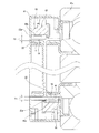
本発明の実施の形態の第1例に就いて、図1〜6を参照しつつ説明する。本例のトルク測定装置付回転伝達装置5は、例えば自動車用の自動変速機に組み込んで使用する。この様なトルク測定装置付回転伝達装置5は、ハウジング(ミッションケース)75と、ベルト式CVT等のインプットシャフト(又はカウンタシャフト)として機能する中空状(中空筒状)のトルク伝達軸6eと、1対の転がり軸受45a、45bと、入力歯車44aと、出力歯車8dと、内軸9aと、第一エンコーダ10と、第二エンコーダ11と、1個のセンサユニット12bとを備える。
First Example of Embodiment
A first example of the embodiment of the present invention will be described with reference to FIGS. The rotation transmitting device 5 with a torque measuring device of this embodiment is used by being incorporated into, for example, an automatic transmission for an automobile. The torque transmission device-equipped rotation transmission device 5 includes a housing (transmission case) 75 and a hollow (hollow cylindrical) torque transmission shaft 6e that functions as an input shaft (or counter shaft) such as a belt CVT. A pair of rolling bearings 45a and 45b, an input gear 44a, an output gear 8d, an inner shaft 9a, a first encoder 10, a second encoder 11, and one sensor unit 12b.

前記トルク伝達軸6eは、炭素鋼の如き合金鋼により中空円筒状に造られたもので、焼き入れ、焼き戻し処理等の熱処理を行い、このトルク伝達軸6eの表面硬さをHV400以上とすると共に、表面炭素濃度を0.2%以上としている。又、本例の場合には、前記トルク伝達軸6eにトルクを入力する為の前記入力歯車44aを、このトルク伝達軸6eの軸方向中間部に、このトルク伝達軸6eとは別体に設けており、トルクを出力する為の前記出力歯車8dを、このトルク伝達軸6eの軸方向一端寄り部分(図1の右端寄り部分)に、このトルク伝達軸6eとは別体に設けている。又、このトルク伝達軸6eのうち、前記入力歯車44a及び前記出力歯車8dが設置された部分を挟んだ両側部分(軸方向他端部分及び軸方向一端部)を、前記1対の転がり軸受45a、45bにより、前記ハウジング75に対し回転自在に支持している。   The torque transmission shaft 6e is made of an alloy steel such as carbon steel in a hollow cylindrical shape and is subjected to heat treatment such as quenching and tempering treatment, and the surface hardness of the torque transmission shaft 6e is made HV400 or more. And the surface carbon concentration is 0.2% or more. Further, in the case of the present embodiment, the input gear 44a for inputting a torque to the torque transmission shaft 6e is provided in the axially intermediate portion of the torque transmission shaft 6e separately from the torque transmission shaft 6e. The output gear 8d for outputting a torque is provided separately from the torque transmission shaft 6e at a portion near the one end in the axial direction of the torque transmission shaft 6e (portion near the right end in FIG. 1). Further, of the torque transmission shaft 6e, both side portions (the other end portion in the axial direction and one end portion in the axial direction) sandwiching the portion where the input gear 44a and the output gear 8d are installed are the pair of rolling bearings 45a. , 45b supports the housing 75 rotatably.

前記入力歯車44a及び前記出力歯車8dは、炭素鋼の如き合金鋼製のはすば歯車又は平歯車であり、前記トルク伝達軸6eとは別体に設けられている。この為に、前記入力歯車44a及び前記出力歯車8dの嵌合部に関して、同心性を確保する為の円筒面嵌合部と、相対回転を防止する為のインボリュートスプライン係合部とを、軸方向に隣接配置した構成を採用している。   The input gear 44a and the output gear 8d are helical gears or spur gears made of alloy steel such as carbon steel, and are provided separately from the torque transmission shaft 6e. Therefore, with respect to the fitting portion of the input gear 44a and the output gear 8d, a cylindrical surface fitting portion for securing concentricity and an involute spline engaging portion for preventing relative rotation in the axial direction It has adopted the configuration arranged adjacent to.

前記両転がり軸受45a(45b)は、例えば深溝型、アンギュラ型等の玉軸受、円すいころ軸受、円筒ころ軸受、ラジアルニードル軸受、自動調心ころ軸受等(図示の例は玉軸受)であり、それぞれが円環状の外輪52(52a)及び内輪51(51a)と、複数個の転動体とから構成されている。このうちの外輪52(52a)は、使用時にも回転しない静止輪であり、前記ハウジング75に内嵌固定されている。前記内輪51(51a)は、使用時に回転する回転輪であり、前記トルク伝達軸6eに外嵌固定されている。前記各転動体は、前記外輪52(52a)の軸方向中間部内周面に形成された外輪軌道と、前記内輪51(51a)の軸方向中間部外周面に形成された内輪軌道との間に、保持器により保持された状態で、転動自在に設けられている。又、本例の場合には、前記両転がり軸受45a、45b同士で、互いの接触角を逆向きとしている。   The two rolling bearings 45a (45b) are, for example, deep groove type, angular type ball bearings, tapered roller bearings, cylindrical roller bearings, radial needle bearings, self-aligning roller bearings, etc. (the example shown is a ball bearing), Each is comprised from the annular | circular shaped outer ring | wheel 52 (52a) and the inner ring | wheel 51 (51a), and several rolling elements. Among these, the outer ring 52 (52a) is a stationary ring which does not rotate even in use, and is fixedly fitted in the housing 75. The inner ring 51 (51a) is a rotating ring that rotates in use, and is externally fitted and fixed to the torque transmission shaft 6e. Each of the rolling elements is between the outer ring raceway formed on the inner circumferential surface of the outer ring 52 (52a) in the axial direction and the inner ring track formed on the outer circumferential surface of the inner ring 51 (51a) in the axial direction. And, in a state of being held by a cage, provided so as to be freely rotatable. Further, in the case of this example, the contact angles of the two rolling bearings 45a and 45b are opposite to each other.

前記内軸9aは、炭素鋼の如き合金鋼又は合成樹脂により略円柱状(又は円管状)に造られたもので、前記トルク伝達軸6eの内径側に、このトルク伝達軸6eと同心に配置されている。又、前記内軸9aは、その軸方向一端部(図1の右端部)を、このトルク伝達軸6eの軸方向一端部に相対回転不能に連結すると共に、その軸方向他端部(図1の左端部)を、前記トルク伝達軸6eの軸方向他端開口から軸方向他側に突出させている。図示の構造の場合には、前記内軸9aの軸方向一端部を、前記トルク伝達軸6eの軸方向一端部に相対回転不能に連結する為に、この内軸9aの軸方向一端部に設けた大径部41の外周面と、このトルク伝達軸6eの軸方向一端部内周面とを、相対回転不能に締り嵌めにより嵌合固定している。尚、これら両周面同士を、相対回転不能に連結する為に、例えばインボリュートスプラインやキーによる係合を採用する事もできる。又、本例の場合には、前記内軸9aのうち、前記大径部41から軸方向に外れた部分の外周面と、前記トルク伝達軸6eの内周面との間部分には、軸方向全長且つ全周に亙って、隙間(微小隙間)が設けられている。この間部分には、潤滑油を充満させて、フィルムダンパとして機能させる事もできる。   The inner shaft 9a is made of an alloy steel such as carbon steel or a synthetic resin in a substantially cylindrical shape (or a round tubular shape), and disposed concentrically with the torque transmission shaft 6e on the inner diameter side of the torque transmission shaft 6e. It is done. The inner shaft 9a has one axial end (right end in FIG. 1) coupled to one axial end of the torque transmission shaft 6e in a relatively non-rotatable manner, and the other axial end (FIG. 1). The left end portion of the torque transmission shaft 6e protrudes from the other end in the axial direction of the torque transmission shaft 6e in the other axial direction. In the case of the illustrated structure, one axial end of the inner shaft 9a is provided at one axial end of the inner shaft 9a so as to be non-rotatably connected to the axial one end of the torque transmission shaft 6e. The outer peripheral surface of the large diameter portion 41 and the inner peripheral surface of one end portion in the axial direction of the torque transmission shaft 6e are fitted and fixed in a non-relatively rotatable manner by interference fit. In addition, in order to connect these both surrounding surfaces so that relative rotation is impossible, engagement by an involute spline or a key is also employable, for example. Further, in the case of the present embodiment, in the portion between the outer peripheral surface of the portion of the inner shaft 9a which is axially deviated from the large diameter portion 41 and the inner peripheral surface of the torque transmission shaft 6e, A gap (a minute gap) is provided over the entire length in the direction and the entire circumference. In the meantime, lubricating oil may be filled to function as a film damper.

前記第一エンコーダ10は、前記転がり軸受45aを構成する内輪51に支持固定されている。言い換えれば、この第一エンコーダ10は、この転がり軸受45aを構成する内輪51を介して、前記トルク伝達軸6eの軸方向他端寄り部分に間接的に取り付けられている。この為、前記第一エンコーダ10は、このトルク伝達軸6eの軸方向他端寄り部分と共に(同期して)回転可能である。これに対し、前記第二エンコーダ11は、前記内軸9aのうちで、前記トルク伝達軸6eの軸方向他端開口から軸方向他側に突出した部分(軸方向他端部)に外嵌固定されている。言い換えれば、前記第二エンコーダ11は、前記内軸9aを介して、前記トルク伝達軸6eの軸方向一端部に間接的に取り付けられている。この為、前記第二エンコーダ11は、このトルク伝達軸6eの軸方向一端部と共に(同期して)回転可能である。   The first encoder 10 is supported and fixed to an inner ring 51 constituting the rolling bearing 45 a. In other words, the first encoder 10 is indirectly attached to a portion near the other end in the axial direction of the torque transmission shaft 6e via the inner ring 51 constituting the rolling bearing 45a. Therefore, the first encoder 10 can be rotated (synchronized) together with a portion near the other axial end of the torque transmission shaft 6e. On the other hand, the second encoder 11 is externally fitted and fixed to a portion (the other end in the axial direction) of the inner shaft 9a that protrudes to the other side in the axial direction from the other end in the axial direction of the torque transmission shaft 6e. It is done. In other words, the second encoder 11 is indirectly attached to one axial end of the torque transmission shaft 6e via the inner shaft 9a. Therefore, the second encoder 11 can be rotated (synchronized) with one axial end of the torque transmission shaft 6e.

又、前記第一、第二両エンコーダ10、11は、前記転がり軸受45aを構成する内輪51又は前記内軸9aの軸方向他端部に支持固定される、磁性金属板から造られた断面クランク形で円環状の支持環14、15と、これら各支持環14、15の外周面に固定された、ゴム、合成樹脂等の高分子材料中に磁性粉を分散させて全体を円筒状とした、ゴム磁石、プラスチック磁石等の永久磁石製のエンコーダ本体16、17とから成る。尚、これらエンコーダ本体16、17中に含有する磁性粉としては、例えば、ストロンチウムフェライト、バリウムフェライト等のフェライト系の磁性粉や、サマリウム−鉄、サマリウム−コバルト、ネオジウム−鉄−ボロン等の希土類元素の磁性粉を採用できる。そして、前記第一エンコーダ10を構成するエンコーダ本体16の外周面を、第一被検出面18とし、又、前記第二エンコーダ11を構成するエンコーダ本体17の外周面を、第二被検出面19としている。これら第一、第二両被検出面18、19は、互いの直径が等しく、互いに同心に、且つ、軸方向に隣り合う状態で近接(例えば軸方向に10mm以内、好ましくは5mm以内の間隔をあけて)配置されている。又、前記第一、第二両被検出面18、19には、それぞれS極とN極とが、円周方向に関して交互に且つ等ピッチで配置されており、磁気特性を円周方向に関して交互に且つ等ピッチで変化させている。前記第一、第二両被検出面18、19の磁極(S極、N極)の総数は、互いに一致している。尚、第一エンコーダ(エンコーダ本体)を、内輪に対して支持環を介する事なく直接取り付けても良い。又、第二エンコーダを構成する支持環の内周面に雌ねじを形成し、この雌ねじを内軸の軸方向他端部に形成した雄ねじ部に螺合させる事により、第二エンコーダを内軸の軸方向他端部に取り付けても良い。   The first and second encoders 10 and 11 are supported on and fixed to the inner ring 51 constituting the rolling bearing 45a or the other axial end of the inner shaft 9a, and are made of a magnetic metal plate and made of a magnetic crank The magnetic powder is dispersed in a polymer material such as rubber or synthetic resin fixed on the outer peripheral surface of the annular support rings 14 and 15 and the support rings 14 and 15 to make the whole cylindrical. And encoder bodies 16 and 17 made of permanent magnets such as rubber magnets and plastic magnets. Examples of magnetic powder contained in the encoder main bodies 16 and 17 include ferrite-based magnetic powders such as strontium ferrite and barium ferrite, and rare earth elements such as samarium-iron, samarium-cobalt, neodymium-iron-boron, etc. Magnetic powder can be adopted. The outer peripheral surface of the encoder main body 16 constituting the first encoder 10 is a first detected surface 18, and the outer peripheral surface of the encoder main body 17 constituting the second encoder 11 is a second detected surface 19. And The first and second detection surfaces 18 and 19 have the same diameter, are concentric with each other, and axially adjacent to each other (for example, within 10 mm in axial direction, preferably within 5 mm). Opened). Further, on the first and second detection surfaces 18 and 19, S poles and N poles are alternately arranged at equal pitches in the circumferential direction, and magnetic characteristics are alternately arranged in the circumferential direction. And at equal pitches. The total number of magnetic poles (S pole, N pole) of the first and second detection surfaces 18 and 19 is the same as each other. The first encoder (encoder main body) may be directly attached to the inner ring without the support ring. Also, by forming a female screw on the inner peripheral surface of the support ring constituting the second encoder, and screwing this female screw to the male screw portion formed at the other axial end of the inner shaft, the second encoder can be It may be attached to the other axial end.

更に本例の場合には、前記第一センサ21a及び前記第二センサ22aを備えたセンサユニット12bを、前記転がり軸受45aを構成する外輪52に支持固定している。本例の特徴は、前記第一エンコーダ10の支持構造、並びに、前記センサユニット12bの構成及び支持構造にある為、対応する図面を参照しつつ、順次説明する。   Furthermore, in the case of this example, the sensor unit 12b provided with the first sensor 21a and the second sensor 22a is supported and fixed to the outer ring 52 that constitutes the rolling bearing 45a. The features of this embodiment are the supporting structure of the first encoder 10, and the configuration and supporting structure of the sensor unit 12b, and therefore will be sequentially described with reference to the corresponding drawings.

前記第一エンコーダ10の支持構造に就いて、図1及び図2を参照しつつ説明する。この第一エンコーダ10は、前述した通り、前記支持環14と、この支持環14の外周面に固定された前記エンコーダ本体16とから構成されている。このうちの支持環14は、板厚が0.5〜1.3mm程度のSPCC等の圧延鋼板に、プレス加工を施して造られたもので、断面クランク形に構成されており、前記内輪51に内嵌固定する為の小径筒部53と、前記エンコーダ本体16をその外周面に固定した大径筒部54と、これら小径筒部53の軸方向他端部と大径筒部54の軸方向一端部とを連続する円輪部55とを備えている。又、前記支持環14のうちで、前記小径筒部53と前記円輪部55とを連続する屈曲部56a、及び、前記大径筒部54とこの円輪部55とを連続する屈曲部56bの、それぞれの曲率半径(曲げR)は、0.2〜1.3mmの範囲に規制されている。   The support structure of the first encoder 10 will be described with reference to FIGS. 1 and 2. As described above, the first encoder 10 is composed of the support ring 14 and the encoder body 16 fixed to the outer peripheral surface of the support ring 14. Among them, the support ring 14 is formed by pressing a rolled steel plate such as SPCC having a plate thickness of about 0.5 to 1.3 mm, and is formed in a crank shape in cross section. , A large diameter cylindrical portion 54 fixing the encoder main body 16 to the outer peripheral surface thereof, and the other axial end of the small diameter cylindrical portion 53 and a shaft of the large diameter cylindrical portion 54 And an annular portion 55 which is continuous with one end of the direction. Further, in the support ring 14, a bending portion 56 a connecting the small diameter cylindrical portion 53 and the annular portion 55, and a bending portion 56 b connecting the large diameter cylindrical portion 54 and the annular portion 55. The radius of curvature (bending R) of each is regulated in the range of 0.2 to 1.3 mm.

又、本例の場合には、前記内輪51の内周面のうち、軸方向他端部に、軸方向一端部乃至中間部に比べて内径寸法が大きくなった取付段差部57を形成し、この取付段差部57に前記小径筒部53を、圧入締め代が20〜400μm程度となる範囲で圧入固定している。本例の場合には、圧入締め代の値を上記範囲に収める事で、前記第一エンコーダ10の脱落を防止すると共に、圧入時の破損を防止している。前記取付段差部57の内径寸法は、前記内輪51の内周面のうちでこの取付段差部57から軸方向に外れた部分の内径寸法に、前記支持環14の板厚を2倍した値を加えた合計値よりも大きくしている。別の言い方をすれば、前記取付段差部57の径方向の深さ寸法を、前記支持環14(小径筒部53)の板厚(径方向の厚さ)よりも小さくしている。これにより、前記取付段差部57に前記小径筒部53を圧入固定した状態で、この小径筒部53の内周面が前記内輪51の内周面よりも径方向内方に突出しない様にして、この小径筒部53の内周面が前記トルク伝達軸6eの外周面に接触する事を防止している。又、本例の場合には、上述した様に、前記各屈曲部56a、56bの曲率半径を小さい値に規制する事で、前記内輪51の軸方向端面に対する前記円輪部55の当接面積を広く確保して、前記大径筒部54、延いては、この大径筒部54に固定した前記エンコーダ本体16の、前記内輪51に対する同心性を確保する様にしている。   Further, in the case of the present embodiment, an attachment step 57 is formed on the other end in the axial direction of the inner circumferential surface of the inner ring 51, wherein the mounting step 57 has an inner diameter larger than that of the axial end or the middle. The small diameter cylindrical portion 53 is press-fitted and fixed to the mounting step portion 57 in a range where the press-fit interference is about 20 to 400 μm. In the case of the present example, by keeping the value of the press-fit interference within the above range, the first encoder 10 is prevented from coming off and breakage at the time of press-fit is prevented. The inside diameter of the mounting step portion 57 is a value obtained by doubling the plate thickness of the support ring 14 to the inside diameter of a portion of the inner peripheral surface of the inner ring 51 axially deviated from the mounting step portion 57. It is larger than the total value added. In other words, the depth dimension in the radial direction of the mounting step portion 57 is smaller than the plate thickness (radial thickness) of the support ring 14 (small diameter cylindrical portion 53). Thus, in a state in which the small diameter cylindrical portion 53 is press-fitted and fixed to the mounting step portion 57, the inner peripheral surface of the small diameter cylindrical portion 53 does not protrude radially inward of the inner peripheral surface of the inner ring 51. The inner peripheral surface of the small diameter cylindrical portion 53 is prevented from coming into contact with the outer peripheral surface of the torque transmission shaft 6e. Further, in the case of the present embodiment, as described above, the contact radius of the annular portion 55 with the end face in the axial direction of the inner ring 51 is controlled by restricting the radius of curvature of the bent portions 56a and 56b to a small value. In order to ensure the concentricity of the encoder main body 16 fixed to the large diameter cylindrical portion 54 and thus to the large diameter cylindrical portion 54 with respect to the inner ring 51.

尚、本発明を実施する場合に、第一エンコーダ10は、図6に示した様に、内輪51の外周面の軸方向他端部(溝肩部)に、締り嵌めで外嵌固定する構成を採用する事もできる。図示の構造の場合には、第一エンコーダ10を構成する支持環14は、エンコーダ本体16を固定する為の小径筒部53aと、前記内輪51の外周面に外嵌固定する為の大径筒部54aと、これら小径筒部53aの軸方向一端部と大径筒部54aの軸方向他端部とを連続する円輪部55aとを備えており、断面クランク形に構成されている。この様な第一エンコーダ10の支持構造を採用する場合にも、大径筒部54aの圧入締め代の値を20〜400μmに規制したり、この大径筒部54a及び前記小径筒部53aと前記円輪部55aとの間の屈曲部56a、56bの曲率半径の値を0.2〜1.3mmの範囲に規制する事が好ましい。   In the embodiment of the present invention, as shown in FIG. 6, the first encoder 10 is externally fitted and fixed to the other axial end (groove shoulder) of the outer peripheral surface of the inner ring 51 by tight fitting. Can also be adopted. In the case of the illustrated structure, the support ring 14 constituting the first encoder 10 has a small diameter cylindrical portion 53 a for fixing the encoder main body 16 and a large diameter cylinder for externally fitting and fixing to the outer peripheral surface of the inner ring 51. It comprises a portion 54a and an annular portion 55a connecting one axial end of the small diameter cylindrical portion 53a and the other axial end of the large diameter cylindrical portion 54a, and is configured to have a crank shape in cross section. Also in the case of adopting such a supporting structure of the first encoder 10, the value of the press-fit interference of the large diameter cylindrical portion 54a is regulated to 20 to 400 μm, or the large diameter cylindrical portion 54a and the small diameter cylindrical portion 53a It is preferable to regulate the value of the radius of curvature of the bent portions 56a and 56b between the ring portion 55a and the annular portion 55a within a range of 0.2 to 1.3 mm.

次に、前記センサユニット12bの構成及び支持構造に就いて、図1及び図2に加えて、図3〜5を参照しつつ説明する。
本例の場合、前記センサユニット12bを、第一センサ21aと、第二センサ22aと、第一基板58と、第二基板59と、センサ支持ブロック60と、センサキャップ61とを含んで構成している。このうちの第一センサ21a(第二センサ22a)は、図4に示した様に、ホール素子、ホールIC、MR素子(GMR素子、TMR素子、AMR素子を含む)等の磁気検出素子を備えた検出部62a(62b)と、この検出部62a(62b)からそれぞれ引き出された1対の端子63a、63a(63b、63b)と、これら両端子63a、63a(63b、63b)の長さ方向中間部同士を導通させる事なく連結する連結部材64a(64b)とを備えている。又、本例の場合には、前記各端子63a、63a(63b、63b)を略コ字形に折り曲げて、前記第一センサ21a(第二センサ22a)を支持するのに利用している。
Next, the configuration and support structure of the sensor unit 12b will be described with reference to FIGS. 3 to 5 in addition to FIGS.
In the case of this example, the sensor unit 12b includes the first sensor 21a, the second sensor 22a, the first substrate 58, the second substrate 59, the sensor support block 60, and the sensor cap 61. ing. Among them, as shown in FIG. 4, the first sensor 21a (second sensor 22a) is provided with a magnetic detection element such as a Hall element, a Hall IC, an MR element (including a GMR element, a TMR element, an AMR element). Detection unit 62a (62b), a pair of terminals 63a (63b (63b)) drawn from the detection unit 62a (62b), and a length direction of the two terminals 63a (63b (63b)) And a connecting member 64a (64b) for connecting the intermediate portions without conduction. Further, in the case of this example, the respective terminals 63a, 63a (63b, 63b) are bent in a substantially U-shape and used to support the first sensor 21a (the second sensor 22a).

前記センサ支持ブロック60は、合成樹脂製で、部分円環状(円弧板状)に構成されており、円周方向に隣接する部分に1対の取付部65a、65bを軸方向位置をずらした(オフセットした)状態で設けている。本例の場合には、この様な取付部65a、65bに対し、前記第一、第二両センサ21a、22aを取り付けている。具体的には、この第一センサ21aを構成する端子63a、63aの先端部と、前記第二センサ22aを構成する端子63b、63bの先端部とを、軸方向に関して反対向き(向き合う方向)に配置する。そして、コ字形に折り曲げられた前記両端子63a、63aにより、前記取付部65aを径方向両側及び軸方向片側(他端側)から取り囲む様に、前記第一センサ21aをこの取付部65aに支持する。又、同様に、コ字形に折り曲げられた前記両端子63b、63bにより、前記取付部65bを径方向両側及び軸方向片側(一端側)から取り囲む様に、前記第二センサ22aをこの取付部65bに取り付ける。尚、この様に第一、第二センサ21a、22aを取り付けた状態で、前記各検出部62a、62bと前記各連結部材64a、64bとの間で、前記各取付部65a、65bを径方向両側から弾性的に挟持している。又、前記第一、第二両センサ21a、22aを前記センサ支持ブロック60に取り付けた状態で、前記両端子63a、63a、63b、63bの先端部を、前記第一、第二両基板58、59にそれぞれ電気的に接続している。   The sensor support block 60 is made of a synthetic resin and configured in a partial annular shape (arc plate shape), and the positions of the attachment portions 65a and 65b adjacent to each other in the circumferential direction are shifted in the axial direction ( Provided in an offset state). In the case of this example, the first and second sensors 21a and 22a are attached to such attachment parts 65a and 65b. Specifically, the tips of the terminals 63a and 63a constituting the first sensor 21a and the tips of the terminals 63b and 63b constituting the second sensor 22a are directed in the opposite direction (facing direction) in the axial direction. Deploy. The first sensor 21a is supported by the mounting portion 65a so as to surround the mounting portion 65a from both sides in the radial direction and one side in the axial direction (the other end side) by the two terminals 63a and 63a bent in a U shape. Do. Similarly, the second sensor 22a is attached to the attachment portion 65b such that the attachment portion 65b is surrounded from both sides in the radial direction and one axial side (one end side) by the two terminals 63b and 63b bent in a U shape. Attach to In the state where the first and second sensors 21a and 22a are attached in this manner, the attachment portions 65a and 65b are arranged in the radial direction between the detection portions 62a and 62b and the connection members 64a and 64b. It is elastically held from both sides. Further, with the first and second sensors 21a and 22a attached to the sensor support block 60, tip portions of the two terminals 63a, 63a, 63b and 63b correspond to the first and second substrates 58, Each is electrically connected to 59.

前記第一、第二両基板58、59は、略円弧板状に構成されており、前記センサ支持ブロック60の軸方向両側面に支持されている。具体的には、前記第一、第二両基板58、59は、複数個所に形成された係合孔92、92に、前記センサ支持ブロック60の軸方向側面に形成した固定用ピン(係合凸部)81、81を係合(圧入)する事で、このセンサ支持ブロック60の軸方向側面に支持されている。又、本例の場合、前記第一、第二両基板58、59同士を円周方向一端部で電気的に接続すると共に、このうちの第一基板58に対し、ハーネス23を電気的に接続している。   The first and second substrates 58 and 59 are formed in a substantially arc plate shape, and are supported on both side surfaces in the axial direction of the sensor support block 60. Specifically, the first and second substrates 58 and 59 are fixed to the engagement holes 92 formed at a plurality of locations on the axial side surface of the sensor support block 60 (engagement (engagement) By engaging (press-fitting) the convex portions 81, 81, the sensor support block 60 is supported on the side surface in the axial direction. In the case of this example, the first and second substrates 58 and 59 are electrically connected at one end in the circumferential direction, and the harness 23 is electrically connected to the first substrate 58 among them. doing.

本例の場合には、前記センサ支持ブロック60に対し、前記第一、第二両センサ21a、22aを取り付けると共に、前記第一、第二両基板58、59を支持した状態で、これら各部材21a、22a、58、59、60を、前記センサキャップ61内に収納している。このセンサキャップ61は、板厚が0.5〜1.3mm程度のSPCC等の圧延鋼板に、プレス加工を施して造られたもので、全体を略円環状に構成している。具体的には、前記センサキャップ61は、円輪状の底部66と、この底部66の外径側端部から軸方向一端側に向けて直角に折れ曲がる状態で設けられた外側筒部67と、この外側筒部67の軸方向一端部から径方向内方に向けて直角に折れ曲がる状態で設けられた突き当て円輪部68と、この突き当て円輪部68の径方向中間部から軸方向一端側に向け突出する状態で設けられた支持筒部69とを備えている。   In the case of this example, while attaching the first and second sensors 21a and 22a to the sensor support block 60 and supporting the first and second substrates 58 and 59, the respective members are provided. 21a, 22a, 58, 59, 60 are accommodated in the sensor cap 61. The sensor cap 61 is formed by pressing a rolled steel plate such as SPCC having a plate thickness of about 0.5 to 1.3 mm, and has a substantially annular shape as a whole. Specifically, the sensor cap 61 has an annular bottom portion 66, an outer cylindrical portion 67 provided so as to be bent at a right angle from the outer diameter side end of the bottom portion 66 toward one axial end side, and the sensor cap 61 Abutment ring portion 68 provided so as to be bent at a right angle radially inward from one axial end portion of the outer cylindrical portion 67, and one end side in the axial direction from the diametrical middle portion of the butt circle portion 68 And a support cylindrical portion 69 provided so as to project toward the

本例の場合には、上述の様な構成を有する前記センサキャップ61を、前記転がり軸受45aを構成する外輪52に支持固定している。この為に、この外輪52の内周面のうちで、軸方向中央部に形成された外輪軌道70の軸方向他側に設けられた肩部71の軸方向他端部に、内径寸法が大きくなった嵌合段差部72を形成している。そして、この嵌合段差部72に対し前記支持筒部69を、圧入締め代が20〜400μm程度となる範囲で圧入固定している。これにより、前記センサキャップ61の脱落を防止すると共に、圧入時の破損を防止している。又、前記肩部71のうちで、前記外輪軌道70と軸方向に隣接した部分の内径寸法を小さいままとして、前記転がり軸受45aを構成する転動体(玉)73が、前記肩部71に乗り上げるのを防止している。   In the case of this example, the sensor cap 61 having the above-described configuration is supported and fixed to the outer ring 52 that constitutes the rolling bearing 45a. For this reason, of the inner peripheral surface of the outer ring 52, the other end in the axial direction of the shoulder portion 71 provided on the other axial side of the outer ring raceway 70 formed at the axial center has a large inner diameter. A fitting step portion 72 is formed. Then, the support cylindrical portion 69 is press-fitted and fixed to the fitting step portion 72 in a range in which the press-fit interference is about 20 to 400 μm. Thus, the sensor cap 61 is prevented from coming off and breakage at the time of press fitting is prevented. Further, while keeping the inner diameter dimension of a portion of the shoulder 71 adjacent to the outer ring raceway 70 in the axial direction small, the rolling elements (balls) 73 constituting the rolling bearing 45 a ride on the shoulder 71 To prevent.

又、上述の様に互いに組み合わせた、前記第一、第二両センサ21a、22a、前記第一、第二両基板58、59、及び、前記センサ支持ブロック60と、この第一基板58に接続した前記ハーネス23の一端部とを、図示しないエポキシ系接着剤やシリコン系接着剤等の樹脂系接着剤により封止(この樹脂部材に包埋)した状態で、前記センサキャップ61の内側に前記各固定用ピン81、81を利用して保持固定している。又、この状態で、前記ハーネス23の残部は、前記底部66の一部に形成したハーネス引出孔74を通じて軸方向に引き出している。又、本例の場合には、前記センサキャップ61を前記外輪52の嵌合段差部72に圧入固定した状態で、内側に設置された前記第一センサ21aを構成する検出部62aを、前記第一エンコーダ10の外周面(第一被検出面18)に対し径方向に関する微小隙間を介して対向させると共に、前記第二センサ22aを構成する検出部62bを、前記第二エンコーダ11の外周面(第二被検出面19)に対し径方向に関する微小隙間を介して対向させている。この為、前記第一センサ21aは、前記第一エンコーダ10の磁気特性変化に対応して出力信号を変化させ、前記第二センサ22aは、前記第二エンコーダ11の磁気特性変化に対応して出力信号を変化させる。そして、前記第一、第二両センサ21a、22aの出力信号を、軸方向に引き出された1本のハーネス23を通じて、図示しない演算器に送信する。又、このハーネス23を通じて、前記第一、第二両センサ21a、22aに電力を供給する。   Also, the first and second sensors 21a and 22a, the first and second substrates 58 and 59, the sensor support block 60, and the first substrate 58 are connected to each other as described above. In the state where it is sealed (embedded in this resin member) with a resin-based adhesive such as an epoxy-based adhesive or a silicon-based adhesive (not shown), the above-mentioned harness 23 is The respective holding pins 81 and 81 are used to hold and fix. Further, in this state, the remaining part of the harness 23 is axially drawn through the harness drawing hole 74 formed in a part of the bottom 66. Further, in the case of this example, with the sensor cap 61 press-fitted and fixed to the fitting step portion 72 of the outer ring 52, the detecting portion 62a constituting the first sensor 21a installed inside is An outer peripheral surface of the second encoder 11 (a first detection surface 18) is opposed to the outer peripheral surface (first detected surface 18) with a minute gap in the radial direction, and the detection unit 62b configuring the second sensor 22a The second detection target surface 19) is opposed to the second detection target surface 19) via a minute gap in the radial direction. Therefore, the first sensor 21a changes the output signal in response to the change in the magnetic characteristic of the first encoder 10, and the second sensor 22a outputs in response to the change in the magnetic characteristic of the second encoder 11. Change the signal. Then, the output signals of the first and second sensors 21a and 22a are transmitted to an arithmetic unit (not shown) through a single harness 23 drawn in the axial direction. Further, power is supplied to the first and second sensors 21a and 22a through the harness 23.

以上の様な構成を有する本例のトルク測定装置付回転伝達装置5の場合、前記センサユニット12bを構成する第一、第二両センサ21a、22aの出力信号は、前記トルク伝達軸6eと共に前記第一、第二両エンコーダ10、11が回転する事に伴い、それぞれ周期的に変化する。ここで、この変化の周波数(及び周期)は、前記トルク伝達軸6eの回転速度に見合った値をとる。従って、これら周波数(又は周期)と回転速度との関係を予め調べておけば、この周波数(又は周期)に基づいて、この回転速度を求められる。又、前記トルク伝達軸6eによりトルクを伝達する際には、前記入力歯車44a及び前記出力歯車8dとの間部分が弾性的に捩れ変形する事に伴い、前記トルク伝達軸6eの軸方向両端部同士(第一、第両二エンコーダ10、11同士)が回転方向に相対変位する。そして、この様に第一、第両二エンコーダ10、11同士が回転方向に相対変位する結果、前記第一、第二両センサ21a、22aの出力信号同士の間の位相差比(=位相差/1周期)が変化する。ここで、この位相差比は、前記トルクに見合った値をとる。従って、これら位相差比とトルクとの関係を予め調べておけば、この位相差比に基づいて、このトルクを算出する事ができる。尚、この算出処理は、前記演算器により行う。この為、この演算器には、予め理論計算や実験により調べておいた、前記位相差比と前記トルクとの関係を、計算式やマップ等の型式で組み込んでおく。   In the case of the rotation transmitting device 5 with a torque measuring device of the present example having the above configuration, the output signals of the first and second sensors 21a and 22a that constitute the sensor unit 12b together with the torque transmitting shaft 6e As the first and second encoders 10 and 11 rotate, they periodically change. Here, the frequency (and period) of this change takes a value commensurate with the rotational speed of the torque transmission shaft 6e. Therefore, if the relationship between the frequency (or period) and the rotational speed is examined in advance, the rotational speed can be determined based on the frequency (or period). Further, when torque is transmitted by the torque transmission shaft 6e, both end portions in the axial direction of the torque transmission shaft 6e are elastically deformed as a portion between the input gear 44a and the output gear 8d is elastically distorted. The first and second encoders 10 and 11 are displaced relative to each other in the rotational direction. Then, as a result of the relative displacement of the first and second encoders 10 and 11 relative to each other in the rotational direction, the phase difference ratio between the output signals of the first and second sensors 21a and 22a (= phase difference) / 1 cycle) changes. Here, the phase difference ratio takes a value corresponding to the torque. Therefore, if the relationship between the phase difference ratio and the torque is examined in advance, this torque can be calculated based on the phase difference ratio. The calculation process is performed by the computing unit. For this reason, the relationship between the phase difference ratio and the torque, which has been investigated in advance by theoretical calculation or experiment, is incorporated in this computing unit in the form of a calculation formula, a map or the like.

特に本例のトルク測定装置付回転伝達装置5によれば、センサの取り付け作業性を良好にできると共に、ハーネスの配線作業の簡略化を図れ、コスト及び重量の低減を図れる。
即ち、本例の場合には、前記トルク伝達軸6eの軸方向一端部の位相を、このトルク伝達軸6eの内径側に配置され、その軸方向他端部がこのトルク伝達軸6eの軸方向他端開口から突出した前記内軸9aに伝達する事ができる。この為、このトルク伝達軸6eの軸方向他端部の位相を検出する為の前記第一エンコーダ10と、このトルク伝達軸6eの軸方向一端部の位相を検出する為の第二エンコーダ11とを、このトルク伝達軸6eの軸方向に関して他端側部分に隣接配置する(まとめて配置する)事ができる。従って、本例の場合には、前記第一、第二両センサ21a、22aを前記センサ支持ブロック60に保持した1個のセンサユニット12bを使用できる為、センサの取り付け作業性を良好にできる。具体的には、前記センサキャップ61を、前記転がり軸受45aを構成する外輪52に取り付ける作業を1回行うだけで、前記第一、第二両センサ21a、22aを高精度に位置決めする事ができる。又、ハーネスの本数を2本{ハーネス4、4(図38参照)}から1本{ハーネス23(図1〜3参照)}に減らす事ができる為、ハーネスの配線作業の簡略化を図れる(取り回し性を良好にできる)と共に、コスト及び重量の低減を図れる。
In particular, according to the rotation transmitting device 5 with a torque measuring device of the present embodiment, the attachment workability of the sensor can be improved, the wiring operation of the harness can be simplified, and the cost and the weight can be reduced.
That is, in the case of this example, the phase of one axial end portion of the torque transmission shaft 6e is disposed on the inner diameter side of the torque transmission shaft 6e, and the other axial end portion is the axial direction of the torque transmission shaft 6e. It can transmit to the said inner shaft 9a protruded from the other end opening. Therefore, the first encoder 10 for detecting the phase of the other axial end of the torque transmission shaft 6e, and the second encoder 11 for detecting the phase of one axial end of the torque transmission shaft 6e Can be disposed adjacent to the other end portion in the axial direction of the torque transmission shaft 6e (arranged together). Therefore, in the case of this example, since one sensor unit 12b holding the first and second sensors 21a and 22a on the sensor support block 60 can be used, the attachment workability of the sensor can be improved. Specifically, the first and second sensors 21a and 22a can be positioned with high accuracy by performing the operation of attaching the sensor cap 61 to the outer ring 52 constituting the rolling bearing 45a only once. . In addition, since the number of harnesses can be reduced from two {harness 4, 4 (see FIG. 38)} to one {harness 23 (see FIGS. 1 to 3)}, the wiring operation of the harness can be simplified The cost and weight can be reduced along with the good manageability.

又、本例の場合には、前記第一、第二両センサ21a、22aを支持した前記センサキャップ61を、前記転がり軸受45aを構成する外輪52に支持固定している為、この転がり軸受45aを利用して、この転がり軸受45aを構成する内輪51に支持固定された前記第一エンコーダ10に対する前記第一センサ21aの位置決めを容易に図る事できる。この為、これら第一エンコーダ10と第一センサ21aとの位置関係を、容易に且つ厳密に規制する事ができる。又、本例の場合には、前記第二センサ22aに就いても、前記転がり軸受45aを利用して位置決めを図る事ができる。従って、前記第一、第二両センサ21a、22aの検出部と、前記第一、第二両エンコーダ10、11(特に内輪に支持された第一エンコーダ10)の被検出面(第一、第二両被検出面18、19)との径方向に関する隙間を、容易に且つ厳密に管理する事が可能になる。   Further, in the case of the present embodiment, since the sensor cap 61 supporting the first and second sensors 21a and 22a is supported and fixed to the outer ring 52 constituting the rolling bearing 45a, the rolling bearing 45a The first sensor 21a can be easily positioned with respect to the first encoder 10 supported and fixed to the inner ring 51 constituting the rolling bearing 45a. Therefore, the positional relationship between the first encoder 10 and the first sensor 21a can be easily and strictly regulated. Further, in the case of the present embodiment, even with the second sensor 22a, positioning can be achieved using the rolling bearing 45a. Therefore, the detection surfaces (first, second, and third portions) of the detection portions of the first and second sensors 21a and 22a and the first and second encoders 10 and 11 (particularly, the first encoder 10 supported on the inner ring) It is possible to easily and strictly manage the gap in the radial direction with the two detection surfaces 18, 19).

又、本例の場合には、前記第一、第二両センサ21a、22aを構成する端子63a、63bをそれぞれ、これら第一、第二両センサ21a、22aを構成する検出部62a、62bから略コ字形に折れ曲がる状態で引き出しており、これら各端子63a、63bにより、前記センサ支持ブロック60を径方向両側及び軸方向片側から取り囲む様にして、前記第一、第二両センサ21a、22aを前記センサ支持ブロック60に支持している。この為、直線状の端子を例えば放射方向(径方向)又は軸方向に配置する構成を採用した場合に比べて、前記第一、第二両センサ21a、22aの径方向及び軸方向に関する寸法を小さく抑える事ができる。従って、本例の構造によれば、前記第一、第二両センサ21a、22aの小型化を図る事ができる。この結果、これら第一、第二両センサ21a、22aを支持したセンサキャップ61が、前記転がり軸受45aを構成する外輪52よりも径方向外方に突出する事を防止でき、このセンサキャップ61をこの外輪52を内嵌固定した前記ハウジング75の内径側に配置する事が可能になる。   In the case of this example, the terminals 63a and 63b constituting the first and second sensors 21a and 22a are respectively connected to the detection portions 62a and 62b constituting the first and second sensors 21a and 22a. The first and second sensors 21a and 22a are drawn out so that the sensor support block 60 is surrounded from both sides in the radial direction and one side in the axial direction by these terminals 63a and 63b. It is supported by the sensor support block 60. For this reason, the dimensions of the first and second sensors 21a and 22a in the radial and axial directions are smaller than in the case where the linear terminals are arranged in, for example, the radial direction (radial direction) or the axial direction. It can be kept small. Therefore, according to the structure of this example, the first and second sensors 21a and 22a can be miniaturized. As a result, the sensor cap 61 supporting the first and second sensors 21a and 22a can be prevented from projecting radially outward beyond the outer ring 52 constituting the rolling bearing 45a. The outer ring 52 can be disposed on the inner diameter side of the housing 75 in which the outer ring 52 is fitted and fixed.

又、本例の場合には、前記第一エンコーダ10を構成する支持環14の小径筒部53を、前記内輪51の内周面の軸方向他端部に形成された取付段差部57に圧入固定している為、前記第一エンコーダ10の第一被検出面18の外径寸法を小さく抑える事が可能になる。この為、前記第一、第二両センサ21a、22aを支持した前記センサキャップ61の外径寸法を小さく抑える事ができる。   Further, in the case of this example, the small diameter cylindrical portion 53 of the support ring 14 constituting the first encoder 10 is press-fit into the mounting step portion 57 formed at the other axial end portion of the inner peripheral surface of the inner ring 51. Since it fixes, it becomes possible to hold down the outside diameter size of the 1st to-be-detected surface 18 of said 1st encoder 10 small. For this reason, the outside diameter size of the sensor cap 61 supporting the first and second sensors 21a and 22a can be reduced.

又、本例の場合には、前記第一、第二両センサ21a、22aを、円周方向に関する位相(位置)をずらした状態で、軸方向に関して互いに反対向きに配置している為、前記センサユニット12bの軸方向寸法の短縮化を図れる。又、前記ハーネス23を軸方向に引き出している為、このセンサユニット12bを取り付けた前記転がり軸受45aを、前記ハウジング75に内嵌固定する際に、前記ハーネス23が邪魔にならずに済み、取り付け作業性が低下する事を防止できる。   Further, in the case of this example, since the first and second sensors 21a and 22a are arranged in mutually opposite directions in the axial direction, with the phases (positions) in the circumferential direction being shifted. The axial dimension of the sensor unit 12b can be shortened. Further, since the harness 23 is drawn out in the axial direction, when the rolling bearing 45a to which the sensor unit 12b is attached is fixedly fitted to the housing 75, the harness 23 does not get in the way, It is possible to prevent the decrease in workability.

又、前記第一エンコーダ10を、前記トルク伝達軸6eに比べて、寸法が小さく且つ重量の軽い前記転がり軸受45aを構成する内輪51に取り付けている為、この第一エンコーダ10を、前記トルク伝達軸6eに直接取り付ける場合に比べて、この第一エンコーダ10の取り付け作業性を良好にする事ができる。更に、本例の場合には、前記トルク伝達軸6eの表面硬さをHV400以上とすると共に、表面炭素濃度を0.2%以上としている為、このトルク伝達軸6eの耐久性の向上を図れる。従って、本例のトルク測定装置付回転伝達装置5を、自動車や風力発電装置等、特に耐久性が要求される用途に好ましく適用できる。しかも、本例の場合には、前記トルク伝達軸6eを前記両転がり軸受45a、45bにより回転自在に支持している為、滑り軸受により支持する構成を採用した場合に比べて、前記トルク伝達軸6eに作用する摩擦トルクを小さく抑えられる。この為、このトルク伝達軸6eが伝達するトルクを大きく確保できて、前記第一、第二両センサ21a、22aの出力信号から得られるトルクの測定精度を良好にできる。   Further, since the first encoder 10 is attached to the inner ring 51 constituting the rolling bearing 45a which is smaller in size and lighter in weight than the torque transmission shaft 6e, the torque transmission of the first encoder 10 is achieved. As compared with the case of direct attachment to the shaft 6e, the attachment workability of the first encoder 10 can be improved. Furthermore, in the case of this example, the surface hardness of the torque transmission shaft 6e is set to HV 400 or more, and the surface carbon concentration is set to 0.2% or more, so the durability of the torque transmission shaft 6e can be improved. . Therefore, the rotation transmitting device 5 with a torque measuring device of the present embodiment can be preferably applied to an automobile, a wind turbine, and the like, in particular, for applications where durability is required. Moreover, in the case of the present example, since the torque transmission shaft 6e is rotatably supported by the two rolling bearings 45a and 45b, the torque transmission shaft is compared to the case where a configuration supported by a slide bearing is employed. The friction torque acting on 6e can be kept small. Therefore, the torque transmitted by the torque transmission shaft 6e can be secured large, and the measurement accuracy of the torque obtained from the output signals of the first and second sensors 21a and 22a can be improved.

[実施の形態の第2例]
本発明の実施の形態の第2例に就いて、図7〜9を参照しつつ説明する。本例の特徴は、トルク伝達軸6eの内径側に配置した内軸9cを、前記実施の形態の第1例の場合の様な中実状ではなく、中空筒状(円管状)とした点にある。
Second Example of Embodiment
A second example of the embodiment of the present invention will be described with reference to FIGS. The feature of this embodiment is that the inner shaft 9c disposed on the inner diameter side of the torque transmission shaft 6e is not a solid shape as in the first embodiment of the embodiment but a hollow cylindrical (circular tubular) shape. is there.

特に、図7に示した構造の場合には、内軸9cの中心に、この内軸9cの軸方向両端面にのみ開口した軸方向に長い貫通孔76を形成している。これにより、前記内軸9cの軽量化を図っている。   In particular, in the case of the structure shown in FIG. 7, an axially long through hole 76 is formed at the center of the inner shaft 9c only at both axial end surfaces of the inner shaft 9c. Thus, the weight of the inner shaft 9c is reduced.

これに対し、変形例である図8、9に示した構造の場合には、内軸9cの軸方向複数箇所(図示の例では2箇所)に、径方向内端部を貫通孔76に開口させると共に、径方向外端部をこの内軸9cの外周面に開口させた分岐孔77a、77bを形成している。又、トルク伝達軸6e並びにこのトルク伝達軸6eに支持固定された入力歯車44a及び出力歯車8dのうち、軸方向に関して前記各分岐孔77a、77bと整合する部分に、径方向に貫通した連通孔78a、78bを形成している。この様な構成を採用する事により、前記貫通孔76、前記各分岐孔77a、77b、及び、前記各連通孔78a、78bを通じて、前記トルク伝達軸6eの径方向外方に配置された、転がり軸受45a、45bや前記入力歯車44a及び前記出力歯車8d等に、潤滑油を供給する様にしている。   On the other hand, in the case of the structure shown in FIGS. 8 and 9 which is a modification, the radially inner end is opened in the through hole 76 at a plurality of axial positions (two in the illustrated example) of the inner shaft 9c. In addition to the above, branch holes 77a and 77b are formed with the radially outer end portion opened to the outer peripheral surface of the inner shaft 9c. Further, a communication hole penetrating in a radial direction in a portion of the torque transmission shaft 6e and the input gear 44a and the output gear 8d supported and fixed to the torque transmission shaft 6e in alignment with the branch holes 77a and 77b in the axial direction. 78a, 78b are formed. By adopting such a configuration, rolling is arranged radially outward of the torque transmission shaft 6e through the through hole 76, the branch holes 77a and 77b, and the communication holes 78a and 78b. Lubricating oil is supplied to the bearings 45a, 45b, the input gear 44a, the output gear 8d, and the like.

更に、前記図9に示した構造の場合には、前記内軸9cの外周面のうち、軸方向に関して前記各分岐孔77a、77bの開口部と整合する部分に、径方向に凹んだ内径側油溝79a、79bを全周に亙り形成すると共に、前記トルク伝達軸6eの内周面のうち、軸方向に関して前記各連通孔78a、78bの開口部と整合する部分に、径方向に凹んだ外径側油溝80a、80bを形成している。そして、前記各内径側油溝79a、79bとこれら各外径側油溝80a、80bとを径方向に対向させて、当該部分に比較的広い空間を形成している。これにより、前記トルク伝達軸6eの内側を通じて供給される潤滑油の流動性を向上させて、このトルク伝達軸6eの径方向外方に配置された各部材に効率良く潤滑油を供給できる様にしている。
その他の構成及び作用効果に就いては、前記実施の形態の第1例の場合と同様である。
Further, in the case of the structure shown in FIG. 9, the radially inner side of the outer peripheral surface of the inner shaft 9c is aligned with the opening of each of the branch holes 77a and 77b in the axial direction. The oil grooves 79a and 79b are formed over the entire circumference, and the inner peripheral surface of the torque transmission shaft 6e is recessed in the radial direction in a portion aligned with the openings of the communication holes 78a and 78b in the axial direction. Outer diameter side oil grooves 80a and 80b are formed. The radially inner oil grooves 79a and 79b and the radially outer oil grooves 80a and 80b are radially opposed to each other to form a relatively wide space in the portion. As a result, the flowability of the lubricating oil supplied through the inside of the torque transmission shaft 6e is improved, so that the lubricating oil can be efficiently supplied to each member disposed radially outward of the torque transmission shaft 6e. ing.
The other configurations and effects are similar to those of the first example of the embodiment.

[実施の形態の第3例]
本発明の実施の形態の第3例に就いて、図10〜11を参照しつつ説明する。本例の特徴は、実施の形態の第1例の構造から内軸を省略すると共に、第一エンコーダ10及び第一センサ21aの組と、第二エンコーダ11及び第二センサ22aの組とを、軸方向に離隔した状態で、トルク伝達軸6eの軸方向両側にそれぞれ配置した点にある。その他の部分の構成及び作用効果に就いては、前記実施の形態の第1例の場合と同様であるので、以下、本例の特徴部分を説明する。
Third Example of Embodiment
A third example of the embodiment of the present invention will be described with reference to FIGS. The feature of this example is that the inner shaft is omitted from the structure of the first example of the embodiment, and a set of the first encoder 10 and the first sensor 21a and a set of the second encoder 11 and the second sensor 22a In a state where they are separated in the axial direction, they are disposed at both axial sides of the torque transmission shaft 6e. The configuration and effects of the other parts are the same as those of the first example of the embodiment, so the characteristic parts of this example will be described below.

本例の場合、前記トルク伝達軸6eの軸方向両端部を、ハウジング75に対し、1対の転がり軸受45a、45bにより、回転自在に支持している。そして、前記第一、第二エンコーダ10、11のうち、第一エンコーダ10を、前記転がり軸受45aを構成する内輪51に支持固定している。言い換えれば、この第一エンコーダ10は、この転がり軸受45aを構成する内輪51を介して、前記トルク伝達軸6eの軸方向他端部に間接的に取り付けられている。この為、前記第一エンコーダ10は、このトルク伝達軸6eの軸方向他端部と共に(同期して)回転可能である。これに対し、前記第二エンコーダ11を、前記転がり軸受45bを構成する内輪51aに支持固定している。言い換えれば、この第二エンコーダ11は、この転がり軸受45bを構成する内輪51aを介して、前記トルク伝達軸6eの軸方向一端部に間接的に取り付けられている。この為、前記第二エンコーダ11は、このトルク伝達軸6eの軸方向一端部と共に(同期して)回転可能である。尚、前記第一、第二両エンコーダ10、11の前記両内輪51、51aに対する支持構造に就いては、前記実施の形態の第1例の場合と同様である。   In the case of this example, the axial direction both ends of the torque transmission shaft 6e are rotatably supported by the housing 75 by a pair of rolling bearings 45a and 45b. The first encoder 10 of the first and second encoders 10 and 11 is supported and fixed to the inner ring 51 constituting the rolling bearing 45 a. In other words, the first encoder 10 is indirectly attached to the other axial end of the torque transmission shaft 6e via the inner ring 51 constituting the rolling bearing 45a. Therefore, the first encoder 10 can be rotated (synchronized) with the other axial end of the torque transmission shaft 6e. On the other hand, the second encoder 11 is supported and fixed to the inner ring 51a constituting the rolling bearing 45b. In other words, the second encoder 11 is indirectly attached to one axial end of the torque transmission shaft 6e via the inner ring 51a constituting the rolling bearing 45b. Therefore, the second encoder 11 can be rotated (synchronized) with one axial end of the torque transmission shaft 6e. The support structure of the first and second encoders 10 and 11 for the inner rings 51 and 51a is the same as that of the first example of the embodiment.

又、本例の場合には、第一、第二両センサ21a、22aのうち、第一センサ21aを、前記転がり軸受45aを構成する外輪52に支持固定しており、第二センサ22aを、前記転がり軸受45bを構成する外輪52aに支持固定している。より具体的には、前記第一センサ21aを、第一基板58と、センサ支持ブロック60aと、センサキャップ61aと組み合わせて、センサユニット12cを構成し、前記外輪52に支持固定している。同様に、前記第二センサ22aに就いても、第二基板59と、センサ保持ブロック60bと、センサキャップ61bと組み合わせて、センサユニット12dを構成し、前記外輪52aに支持固定している。
Further, in the case of this example, the first sensor 21a of the first and second sensors 21a and 22a is supported and fixed to the outer ring 52 constituting the rolling bearing 45a, and the second sensor 22a is It supports and fixes to the outer ring 52a which comprises the said rolling bearing 45b. More specifically, the first sensor 21a is combined with the first substrate 58, the sensor support block 60a, and the sensor cap 61a to form a sensor unit 12c, which is supported and fixed to the outer ring 52. Similarly, the second sensor 22a is combined with the second substrate 59, the sensor holding block 60b, and the sensor cap 61b to form a sensor unit 12d, which is supported and fixed to the outer ring 52a.

本例の場合には、前記各センサ支持ブロック60a、60bとして、合成樹脂製で、部分円環状に構成されており、円周方向1個所にのみ取付部を備えたものを使用している。そして、この取付部に対し、前記第一、第二各センサ21a、22aを、それぞれ取り付けている。具体的には、これら第一、第二各センサ21a、22aを構成する略コ字形の端子63a、63bにより、前記各取付部を、それぞれ径方向両側及び軸方向片側から取り囲む様に、前記第一、第二各センサ21a、22aを前記各取付部に取り付けている。   In the case of the present embodiment, as each of the sensor support blocks 60a and 60b, one made of a synthetic resin and configured in a partially annular shape and having an attachment portion at only one circumferential direction is used. The first and second sensors 21a and 22a are attached to the attachment portion. More specifically, the substantially U-shaped terminals 63a and 63b constituting the first and second sensors 21a and 22a respectively surround the attachment portions from both sides in the radial direction and one side in the axial direction. The first and second sensors 21a and 22a are attached to the attachment portions.

そして、前記第一、第二各センサ21a、22aを構成する端子63a、63bの先端部を、前記各センサ支持ブロック60a、60bの軸方向側面にそれぞれ支持された前記第一、第二各基板58、59に対し、それぞれ電気的に接続している。又、これら第一、第二各基板58、59に対し、それぞれハーネス23、23を電気的に接続している。   Then, the first and second substrates are supported with the tip end portions of the terminals 63a and 63b constituting the first and second sensors 21a and 22a on the axial side surfaces of the sensor support blocks 60a and 60b, respectively. Electrical connections are made to 58 and 59, respectively. The harnesses 23 and 23 are electrically connected to the first and second substrates 58 and 59, respectively.

又、本例の場合には、前記各センサ支持ブロック60a、60bに対し、前記第一、第二各センサ21a、22aを取り付けると共に、前記第一、第二各基板58、59を支持した状態で、これら各部材21a、58、60aを、前記センサキャップ61a内に収納すると共に、前記各部材21b、59、60bを、前記センサキャップ61b内に収納している。そして、これら両センサキャップ61a、61bのうち、一方のセンサキャップ61aを、前記転がり軸受45aを構成する外輪52に支持固定(内嵌固定)し、他方のセンサキャップ61bを、前記転がり軸受45bを構成する外輪52aに支持固定(内嵌固定)している。尚、これら両センサキャップ61a、61bの支持構造に就いても、基本的には、前記実施の形態の第1例の場合と同様である。   In the case of this example, the first and second sensors 21a and 22a are attached to the sensor support blocks 60a and 60b, and the first and second substrates 58 and 59 are supported. The respective members 21a, 58, 60a are accommodated in the sensor cap 61a, and the respective members 21b, 59, 60b are accommodated in the sensor cap 61b. Then, one of the two sensor caps 61a and 61b is supported and fixed (internally fixed) to the outer ring 52 constituting the rolling bearing 45a, and the other sensor cap 61b is mounted on the rolling bearing 45b. Support fixing (internal fitting fixation) is carried out to the outer ring 52a which constitutes. The support structure of both sensor caps 61a and 61b is basically the same as that of the first example of the embodiment.

以上の様な構成により、前記センサキャップ61aの内側に設置された前記第一センサ21aを構成する検出部62aを、前記第一エンコーダ10の外周面(第一被検出面18)に対し径方向に関する微小隙間を介して対向させると共に、前記センサキャップ61bの内側に配置された前記第二センサ22aを構成する検出部62bを、前記第二エンコーダ11の外周面(第二被検出面19)に対し径方向に関する微小隙間を介して対向させている。この為、前記第一センサ21aは、前記第一エンコーダ10の磁気特性変化に対応して出力信号を変化させ、前記第二センサ22aは、前記第二エンコーダ11の磁気特性変化に対応して出力信号を変化させる。そして、前記第一、第二両センサ21a、22aの出力信号を、軸方向にそれぞれ引き出された2本のハーネス23、23を通じて、図示しない演算器に送信する。又、これら各ハーネス23、23を通じて、前記第一、第二各センサ21a、22aに電力を供給する。
尚、本発明を実施する場合に、前記第一、第二両エンコーダ10、11のうち、何れか一方のエンコーダのみを内輪に支持固定し、他方のエンコーダに関しては、トルク伝達軸の端部に直接支持固定する構造を採用しても良い。この場合には、前記第一、第二両センサ21a、22aのうち、前記一方のエンコーダの被検出面にその検出部を対向させる、何れか一方のセンサのみを外輪に支持固定し、他方のセンサに就いてはハウジング等に支持固定する構造を採用しても良い。
With the above-described configuration, the detection portion 62a constituting the first sensor 21a installed inside the sensor cap 61a is in the radial direction with respect to the outer peripheral surface (the first detected surface 18) of the first encoder 10. And the detection portion 62b of the second sensor 22a disposed inside the sensor cap 61b on the outer peripheral surface (the second detection surface 19) of the second encoder 11. It is made to oppose via a minute gap in the radial direction. Therefore, the first sensor 21a changes the output signal in response to the change in the magnetic characteristic of the first encoder 10, and the second sensor 22a outputs in response to the change in the magnetic characteristic of the second encoder 11. Change the signal. Then, the output signals of the first and second sensors 21a and 22a are transmitted to a computing unit (not shown) through the two harnesses 23 and 23 respectively drawn in the axial direction. Further, electric power is supplied to the first and second sensors 21a and 22a through the harnesses 23 and 23, respectively.
When the present invention is practiced, only one of the first and second encoders 10 and 11 is supported and fixed to the inner ring, and the other encoder is attached to the end of the torque transmission shaft. A direct support and fixation structure may be adopted. In this case, of the first and second sensors 21a and 22a, only one of the sensors is supported and fixed to the outer ring, with the detection portion facing the detected surface of the one encoder. The sensor may be supported and fixed to a housing or the like.

以上の様な構成を有する本例のトルク測定装置付回転伝達装置5の場合、第一、第二両センサ21a、22aの出力信号は、前記トルク伝達軸6eと共に前記第一、第二両エンコーダ10、11が回転する事に伴い、それぞれ周期的に変化する。ここで、この変化の周波数(及び周期)は、前記トルク伝達軸6eの回転速度に見合った値をとる。従って、これら周波数(又は周期)と回転速度との関係を予め調べておけば、この周波数(又は周期)に基づいて、この回転速度を求められる。又、前記トルク伝達軸6eによりトルクを伝達する際には、前記入力歯車44aと前記出力歯車8dとの間部分が弾性的に捩れ変形する事に伴い、前記トルク伝達軸6eの軸方向両端部同士(第一、第二両エンコーダ10、11同士)が回転方向に相対変位する。そして、この様に第一、第二両エンコーダ10、11同士が回転方向に相対変位する結果、前記第一、第二両センサ21a、22aの出力信号同士の間の位相差比(=位相差/1周期)が変化する。ここで、この位相差比は、前記トルクに見合った値をとる。従って、これら位相差比とトルクとの関係を予め調べておけば、この位相差比に基づいて、このトルクを求められる。   In the case of the rotation transmitting device 5 with a torque measuring device of the present embodiment having the above configuration, the output signals of the first and second sensors 21a and 22a together with the torque transmitting shaft 6e are the first and second encoders. As 10 and 11 rotate, they change periodically. Here, the frequency (and period) of this change takes a value commensurate with the rotational speed of the torque transmission shaft 6e. Therefore, if the relationship between the frequency (or period) and the rotational speed is examined in advance, the rotational speed can be determined based on the frequency (or period). Further, when torque is transmitted by the torque transmission shaft 6e, both end portions in the axial direction of the torque transmission shaft 6e are deformed as the portion between the input gear 44a and the output gear 8d is elastically twisted and deformed. The first and second encoders 10 and 11 are displaced relative to each other in the rotational direction. Then, as a result of relative displacement of the first and second encoders 10 and 11 relative to each other in the rotational direction as described above, the phase difference ratio between the output signals of the first and second sensors 21 a and 22 a (= phase difference / 1 cycle) changes. Here, the phase difference ratio takes a value corresponding to the torque. Therefore, if the relationship between the phase difference ratio and the torque is examined in advance, the torque can be obtained based on the phase difference ratio.

又、本例のトルク測定装置付回転伝達装置5の場合にも、前記トルク伝達軸6eをハウジング75に回転自在に支持する為の軸受として、1対の転がり軸受45a、45bを使用している為、例えば滑り軸受を使用して支持する場合と比べて、軸受部で生じるフリクションロスを低減できる。この為、前記トルク伝達軸6eに加わるトルクが減少する事を防止でき、トルクの測定精度を確保できる。
その他の構成及び作用効果に就いては、前記実施の形態の第1例の場合と同様である。
Also in the case of the rotation transmitting device 5 with a torque measuring device of this embodiment, a pair of rolling bearings 45a, 45b is used as a bearing for rotatably supporting the torque transmitting shaft 6e on the housing 75. Therefore, it is possible to reduce the friction loss generated in the bearing as compared to the case of supporting using a slide bearing, for example. For this reason, it can prevent that the torque added to the said torque transmission shaft 6e reduces, and it can ensure the measurement precision of a torque.
The other configurations and effects are similar to those of the first example of the embodiment.

[実施の形態の第4例]
本発明の実施の形態の第4例に就いて、図12〜13を参照しつつ説明する。本例の特徴は、センサキャップ61cに対するセンサ支持ブロック60の固定構造にある。即ち、前述した実施の形態の第1例の構造の場合には、図12の(A)に示した様に、センサ支持ブロック60の軸方向側面に設けられた複数の固定用ピン81、81を、センサキャップ61を構成する底部66又は突き当て円輪部68に形成された固定用孔82、82内に圧入する事により、前記センサ支持ブロック60を前記センサキャップ61に対して支持固定している。この様な固定構造を採用した場合、組み付け作業時に、このセンサキャップ61に対する前記センサ支持ブロック60の位置決め(正しい姿勢に規制する事)が難しく、例えば、前記各固定用ピン81、81の中心軸と前記各固定用孔82、82の中心軸とが傾斜した状態等、前記センサ支持ブロック60を正規の位置(姿勢)以外に取り付けようとすると、このセンサ支持ブロック60に過大な応力が加わる可能性がある。この為、このセンサ支持ブロック60に支持固定した第一、第二両センサ21a、22a及び第一、第二両基板58、59にも、応力が加わる可能性があり、これら各部材21a、22a、58、59が故障する可能性がある。又、前記センサ支持ブロック60を前記センサキャップ61に対し、正規の取付位置からずれた位置に一旦固定してしまうと、容易には取り外す事ができず、メンテナンス性の面で問題を生じる可能性がある。
Fourth Example of Embodiment
A fourth example of the embodiment of the present invention will be described with reference to FIGS. The feature of this example is the fixing structure of the sensor support block 60 with respect to the sensor cap 61c. That is, in the case of the structure of the first example of the embodiment described above, as shown in FIG. 12A, the plurality of fixing pins 81, 81 provided on the side surface in the axial direction of the sensor support block 60. The sensor support block 60 is supported and fixed to the sensor cap 61 by pressing the sensor cap 61 into the fixing holes 82 and 82 formed in the bottom portion 66 or the abutting circular portion 68 constituting the sensor cap 61. ing. When such a fixing structure is employed, it is difficult to position the sensor support block 60 with respect to the sensor cap 61 (restrict to a correct posture) at the time of assembling operation. For example, central axes of the fixing pins 81 and 81 If the sensor support block 60 is attached to a position other than the normal position (posture), such as when the center axis of the fixing holes 82 and 82 is inclined, excessive stress may be applied to the sensor support block 60 There is sex. Therefore, stress may be applied to the first and second sensors 21a and 22a and the first and second substrates 58 and 59 supported and fixed to the sensor support block 60. These members 21a and 22a may be used. , 58, 59 may fail. In addition, once the sensor support block 60 is fixed to the sensor cap 61 at a position deviated from the normal mounting position, it can not be easily removed, which may cause a problem in terms of maintainability. There is.

そこで、本例の場合には、図12の(B)に示した様に、センサキャップ61cを構成する底部66a(又は突き当て円輪部68a)に、センサ支持ブロック60に設けられた固定用ピン81、81と同数で且つ等ピッチに配置された固定用孔82a、82aを形成すると共に、これら各固定用ピン81、81をこれら各固定用孔82a、82aに導く為の案内凹溝83、83を形成している。図示の構造の場合には、これら各案内凹溝83、83を、前記底部66aの径方向内端部から径方向外方に直線状に伸長した径方向直線部84、84と、これら各径方向直線部84、84の径方向外端部から前記各固定用孔82a、82aに向けて、円周方向に直線状に伸長した円周方向直線部85、85とから構成している。   Therefore, in the case of this example, as shown in FIG. 12B, the fixing portion provided on the sensor support block 60 at the bottom portion 66a (or the abutting circular portion 68a) constituting the sensor cap 61c. While forming the fixing holes 82a, 82a arranged at the same number and the same pitch as the pins 81, 81, guide grooves 83 for guiding the fixing pins 81, 81 to the fixing holes 82a, 82a. , 83 are formed. In the case of the illustrated structure, the respective guide grooves 83, 83 are radially straight portions 84, 84 linearly extended radially outward from the radial inner end of the bottom portion 66a, and the respective diameters thereof From the radial direction outer end of the direction straight portions 84, 84 toward the fixing holes 82a, 82a, the circumferential straight portions 85, 85 are linearly extended in the circumferential direction.

以上の様な構成を有する本例の場合、前記センサ支持ブロック60を前記センサキャップ61cに固定する際に、前記各固定用ピン81、81を、前記各案内凹溝83、83(径方向直線部84、84及び周方向直線部85、85の順)に沿って同時に(同位相で)移動させた後、前記各固定用孔82a、82aに挿入する事ができる。この為、前記各センサキャップ61cに対する前記センサ支持ブロック60の姿勢を規制する事ができ、前記各固定用ピン81、81の中心軸と前記各固定用孔82a、82aの中心軸とを容易に一致させる事ができる。従って、本例の構造によれば、前記センサ支持ブロック60に過大な応力が加わる事を有効に防止する事ができて、前記第一、第二両センサ21a、22a及び前記第一、第二両基板58、59に故障が生じる事を有効に防止できる。又、前記各固定ピン81、81の中心軸と前記各固定用孔82a、82aとの中心軸とを一致させた状態で、これら各固定用ピン81、81を挿入できる為、これら各固定用ピン81、81を前記各固定用孔82a、82aから取り外す作業が、必要以上に面倒になる事を防止できる。従って、メンテナンス性の面からも有利になる。   In the case of the present example having the above configuration, when fixing the sensor support block 60 to the sensor cap 61c, the fixing pins 81, 81 are used as the guide concave grooves 83, 83 (radial straight line After being moved simultaneously (in the same phase) along the portions 84 and 84 and the circumferential direction straight portions 85 and 85), they can be inserted into the fixing holes 82a and 82a. Therefore, the attitude of the sensor support block 60 with respect to each sensor cap 61c can be regulated, and the central axes of the respective fixing pins 81, 81 and the central axes of the respective fixing holes 82a, 82a can be easily made. It can be matched. Therefore, according to the structure of this embodiment, it is possible to effectively prevent excessive stress from being applied to the sensor support block 60, and the first and second sensors 21a and 22a and the first and second sensors can be prevented. It is possible to effectively prevent the failure of both substrates 58, 59. Further, since the fixing pins 81 and 81 can be inserted in a state where the central axes of the fixing pins 81 and 81 and the central axes of the fixing holes 82a and 82a coincide with each other, these fixing pins 81 and 81 can be inserted. The operation of removing the pins 81, 81 from the fixing holes 82a, 82a can be prevented from being complicated more than necessary. Therefore, it is also advantageous in terms of maintainability.

又、図13には、本例の変形例の構造を示している。このうちの(A)に示した構造の場合には、1対の案内凹溝83aをそれぞれ、径方向直線部84と、これら各径方向直線部84の径方向外端部から固定用孔82aに向けて、円周方向に円弧状に伸長した円周方向円弧部86とから構成している。この様な構成を有する(A)の場合、前記図12の(B)の場合と同様に、固定用ピン81、81を、前記各案内凹溝83a、83aに沿って同時に移動させた後、固定用孔82a、82aに挿入する事が可能になる。   FIG. 13 shows the structure of a modification of this embodiment. In the case of the structure shown in (A) of these, the pair of guide grooves 83a are respectively formed from the radial direction straight portion 84 and the radial direction outer end portion of each of the radial direction straight portions 84 for fixing holes 82a. The circumferential direction arc portion 86 extends in an arc shape in the circumferential direction. In the case of (A) having such a configuration, as in the case of (B) of FIG. 12, after the fixing pins 81, 81 are simultaneously moved along the guide grooves 83a, 83a, It becomes possible to insert into the fixing holes 82a, 82a.

又、(B)に示した構造の場合には、1対の案内凹溝83b、83cをそれぞれ、底部66a(又は突き当て円輪部68a)の径方向内端部から径方向外方に円弧状に伸長した径方向円弧部87a(87b)と、これら各径方向円弧部87a(87b)の径方向外端部から固定用孔82aに向けて、円周方向に円弧状(径方向外方が凸になった円弧状)に伸長した円周方向円弧部86とから構成している。この様な構成の場合、前記径方向円弧部87a(87b)を、円周方向に隣り合う状態で配置された径方向円弧部87b(87a)の径方向外端部を曲率中心とした曲率半径Rの円弧としている。従って、前記(B)の構造の場合、円周方向に隣り合う1対の径方向円弧部87a、87b同士の間で、円周方向に関する凸の向きが逆になっている。又、円周方向に隣り合う1対の固定用孔82a、82a同士の円周方向距離もRに規制している。この様な構成を有する(B)の場合、1対の固定用ピン81、81のうち、何れか一方の固定用ピン81を、円周方向に隣り合う1対の径方向円弧部87a、87bのうち、一方の径方向円弧部87a(87b)の径方向外端部まで移動させた後、他方の固定用ピン81を、他方の径方向円弧部87b(87a)に沿って径方向内方から外方に向けて移動させる。その後、前記両固定用ピン81、81を、前記両円周方向円弧部86、86に沿って同時に移動させ、前記各固定用孔82a、82aに挿入する。   Further, in the case of the structure shown in (B), the pair of guide grooves 83b and 83c are respectively circled radially outward from the radially inner end of the bottom 66a (or the abutting circular portion 68a). An arc shape (radially outward in the circumferential direction) from the radially outer end of the radially extending arc portion 87a (87b) and the radially outer end of each of the radially extending arc portions 87a (87b) toward the fixing hole 82a Is a circular arc portion 86 extended in a convex arc shape). In the case of such a configuration, the radius of curvature with the radially outer end of the radial arc portion 87b (87a) disposed in the circumferentially adjacent state of the radial arc portion 87a (87b) as the center of curvature It is an arc of R. Therefore, in the case of the structure (B), the convex directions in the circumferential direction are reversed between the pair of radial arc portions 87a and 87b adjacent in the circumferential direction. Further, the circumferential distance between the pair of fixing holes 82a adjacent to each other in the circumferential direction is also restricted to R. In the case of (B) having such a configuration, one of the fixing pins 81 of the pair of fixing pins 81 is used as a pair of radial arc portions 87a and 87b adjacent in the circumferential direction. After moving to the radial outer end of one radial arc 87a (87b), the other fixing pin 81 is moved radially inward along the other radial arc 87b (87a). Move outward from the Thereafter, the two fixing pins 81, 81 are simultaneously moved along the two circumferential direction arc parts 86, 86 and inserted into the respective fixing holes 82a, 82a.

又、(C)に示した構造の場合には、1対の案内凹溝83a、83c同士の間で、形状を異ならせている。即ち、これら両案内凹溝83a、83cのうち、一方の案内凹溝83aを、前記(A)に示した場合と同様に、径方向直線部84と、この径方向直線部84の径方向外端部から固定用孔82aに向けて、円周方向に円弧状に伸長した円周方向円弧部86とから構成しているのに対し、他方の案内凹溝83cを、前記(B)の右側に示した構造の場合と同様に、径方向円弧部87bと、これら各径方向円弧部87bの径方向外端部から固定用孔82aに向けて、円周方向に円弧状に伸長した円周方向円弧部86とから構成している。又、(C)に示した構造の場合には、前記径方向円弧部87bを、円周方向に隣り合う状態で配置された前記径方向直線部84の径方向外端部を曲率中心とした曲率半径Rの円弧としている。又、円周方向に隣り合う1対の固定用孔82a、82a同士の円周方向距離をRに規制している。この様な構成を有する(C)の場合、1対の固定用ピン81、81のうち、何れか一方の固定用ピン81を、前記径方向直線部84の径方向外端部まで移動させた後、他方の固定用ピン81を、前記径方向円弧部87bに沿って径方向内方から外方に向けて移動させる。その後、前記両固定用ピン81、81を、前記両円周方向円弧部86、86に沿って同時に移動させ、前記各固定用孔82a、82aに挿入する。   Further, in the case of the structure shown in (C), the shape is made different between the pair of guide grooves 83a and 83c. That is, in the same manner as in the case of (A), one of the two guide concave grooves 83a and 83c is the radial straight portion 84 and the radial outer side of the radial straight portion 84. The other guide concave groove 83c is formed on the right side of the above (B), while the other guide concave groove 83c is formed from the end in the circumferential direction arc portion 86 extending in a circular arc shape toward the fixing hole 82a. In the same manner as in the case of the structure shown in the above, the radially extending arc portion 87 b and a circumferentially extended circumferentially extending arc from the radially outer end of each of the radially extending arc portions 87 b toward the fixing hole 82 a It comprises the direction arc portion 86. Further, in the case of the structure shown in (C), the radially outer end portion of the radially straight portion 84, which is disposed adjacent to the circumferential direction, is the center of curvature of the radially arc portion 87b. It is an arc of curvature radius R. Further, the circumferential distance between the pair of fixing holes 82a adjacent to each other in the circumferential direction is restricted to R. In the case of (C) having such a configuration, either one of the fixing pins 81, 81 is moved to the radially outer end of the radial straight portion 84. After that, the other fixing pin 81 is moved from the radially inward to the outward along the radial arc portion 87b. Thereafter, the two fixing pins 81, 81 are simultaneously moved along the two circumferential direction arc parts 86, 86 and inserted into the respective fixing holes 82a, 82a.

又、(D)に示した構造の場合にも、1対の案内凹溝83b、83a同士の間で、形状を異ならせている。即ち、これら両案内凹溝83b、83aのうち、一方の案内凹溝83bを、前記(B)の左側に示した構造の場合と同様に、径方向円弧部87aと、これら各径方向円弧部87aの径方向外端部から固定用孔82aに向けて、円周方向に円弧状に伸長した円周方向円弧部86とから構成しているのに対し、他方の案内凹溝83aを、前記(A)に示した場合と同様に、径方向直線部84と、この径方向直線部84の径方向外端部から固定用孔82aに向けて、円周方向に円弧状に伸長した円周方向円弧部86とから構成している。又、(D)に示した構造の場合には、前記径方向円弧部87aを、円周方向に隣り合う状態で配置された前記径方向直線部84の径方向外端部を曲率中心とした曲率半径Rの円弧としている。又、円周方向に隣り合う1対の固定用孔82a、82a同士の円周方向距離をRに規制している。この様な構成を有する(D)の場合、1対の固定用ピン81、81のうち、何れか一方の固定用ピン81を、前記径方向直線部84の径方向外端部まで移動させた後、他方の固定用ピン81を、前記径方向円弧部87aに沿って径方向内方から外方に向けて移動させる。その後、前記両固定用ピン81、81を、前記両円周方向円弧部86、86に沿って同時に移動させ、前記各固定用孔82a、82aに挿入する。   Also in the case of the structure shown in (D), the shape is made different between the pair of guide grooves 83b, 83a. That is, as in the case of the structure shown on the left side of the above (B), the guide concave groove 83b of one of the both guide concave grooves 83b and 83a, the radial arc part 87a and the radial arc parts thereof The other guide concave groove 83a is composed of a circular direction circular arc portion 86 extended in a circular arc shape in the circumferential direction from the radially outer end of 87a toward the fixing hole 82a. Similarly to the case shown in (A), a radial straight portion 84 and a circumferentially elongated circular arc shape from the radial outer end of the radial straight portion 84 toward the fixing hole 82 a It comprises the direction arc portion 86. Further, in the case of the structure shown in (D), the radially outer end portion of the radially straight portion 84, which is disposed adjacent to the circumferential direction, is the center of curvature of the radially arc portion 87a. It is an arc of curvature radius R. Further, the circumferential distance between the pair of fixing holes 82a adjacent to each other in the circumferential direction is restricted to R. In the case of (D) having such a configuration, either one of the fixing pins 81, 81 is moved to the radially outer end of the radial straight portion 84. After that, the other fixing pin 81 is moved from the radially inward to the outward along the radial arc portion 87a. Thereafter, the two fixing pins 81, 81 are simultaneously moved along the two circumferential direction arc parts 86, 86 and inserted into the respective fixing holes 82a, 82a.

以上に説明した(A)〜(D)の何れの構造の場合にも、前記12の(B)に示した構造の場合と同様に、前記各固定用ピン81、81の中心軸と前記各固定用孔82a、82aの中心軸とを容易に一致させる事ができる。従って、センサ支持ブロック60に過大な応力が加わる事を有効に防止する事ができて、第一、第二両センサ21a、22a及び第一、第二両基板58、59に故障が生じる事を有効に防止できる。又、前記各固定用ピン81、81を前記各固定用孔82a、82aから取り外す作業が、必要以上に面倒になる事を防止できる為、メンテナンス性の面からも有利になる。
その他の構成及び作用効果に就いては、前記実施の形態の第1例の場合と同様である。
In any of the structures (A) to (D) described above, as in the case of the structure shown in (B) of 12 above, the central axes of the fixing pins 81 and 81 and the respective axes The central axes of the fixing holes 82a and 82a can be easily aligned. Therefore, excessive stress can be effectively prevented from being applied to the sensor support block 60, and failure may occur in the first and second sensors 21a and 22a and the first and second substrates 58 and 59. It can be effectively prevented. Further, the operation of removing the fixing pins 81 from the fixing holes 82a can be prevented from being complicated more than necessary, which is advantageous from the viewpoint of maintenance.
The other configurations and effects are similar to those of the first example of the embodiment.

[実施の形態の第5例]
本発明の実施の形態の第5例に就いて、図14〜16を参照しつつ説明する。本例の特徴は、センサキャップ61と、このセンサキャップ61の内側に配置された第一、第二両基板58、59との間の隙間の大きさを厳密に規制した点にある。前記センサキャップ61の小径化を図るべく、このセンサキャップ61とこのセンサキャップ61の内側に配置された各部材との間の隙間を何ら制限なく小さくした場合、第一基板58又は第二基板59に接続された第一、第二各センサ21a、22aの端子63a、63bや、抵抗、コンデンサといった各種素子93などが、前記センサキャップ61の内面に接触する可能性があり、これら各部材21a、22a、93の損傷の原因になる。又、前記センサキャップ61として、金属製のものを使用した場合には、前記第一基板58や前記第二基板59の回路がショートする可能性がある。
Fifth Example of Embodiment
A fifth example of the embodiment of the present invention will be described with reference to FIGS. The feature of this example is that the size of the gap between the sensor cap 61 and the first and second substrates 58 and 59 disposed inside the sensor cap 61 is strictly regulated. When the gap between the sensor cap 61 and each member disposed inside the sensor cap 61 is reduced without any limitation in order to reduce the diameter of the sensor cap 61, the first substrate 58 or the second substrate 59 may be used. The terminals 63a and 63b of the first and second sensors 21a and 22a connected to each other, and various elements 93 such as a resistor and a capacitor may come in contact with the inner surface of the sensor cap 61. 22a, 93 cause damage. When a metal cap is used as the sensor cap 61, the circuits of the first substrate 58 and the second substrate 59 may short.

そこで、本例の場合には、図14、15に示した様に、センサキャップ61の内面と前記第一基板58及び前記第二基板59との間の隙間の大きさH1、H2を、それぞれ1.15mmよりも大きくなる様に規制し、前記センサキャップ61の内面と前記第一基板58及び前記第二基板59に接続された各種部材との接触を防止している。   Therefore, in the case of this example, as shown in FIGS. 14 and 15, the sizes H1 and H2 of the gap between the inner surface of the sensor cap 61 and the first substrate 58 and the second substrate 59 are respectively determined. It regulates so that it may become larger than 1.15 mm, and a contact with an inner surface of the sensor cap 61 and various members connected to the first substrate 58 and the second substrate 59 is prevented.

次に、前記センサキャップ61の内面と前記第一基板58及び前記第二基板59との間の隙間の大きさを、それぞれ1.15mmよりも大きくした理由について説明する。
先ず、前記第一基板58及び前記第二基板59に接続される素子93のうち、表面実装用のチップ抵抗の厚さは、JIS規格上最大で0.75mmであり、又、使用頻度の高い1608サイズの角型セラミックコンデンサの厚さは、最大で1.00mm程度である。一方、前記第一基板58及び前記第二基板59が固定されるセンサ支持ブロック60の熱膨張量は、このセンサ支持ブロック60の径方向厚さ寸法を10mm、このセンサ支持ブロック60を構成する樹脂材料の熱膨張係数を10×10−5/K、使用時に於ける温度変化(温度上昇量)を150°Cとした場合に、0.15mmになる。そこで、本例の場合には、前記第一基板58及び前記第二基板59に接続される素子93のうち、厚さ寸法が最大になると考えられる、1608サイズの角型セラミックコンデンサの厚さ1.00mmに、前記センサ支持ブロック60の熱膨張量分の0.15mmを加えて、1.15mmなる値を決定している。
Next, the reason why the size of the gap between the inner surface of the sensor cap 61 and the first substrate 58 and the second substrate 59 is larger than 1.15 mm will be described.
First, among the elements 93 connected to the first substrate 58 and the second substrate 59, the thickness of the chip resistance for surface mounting is at most 0.75 mm according to the JIS standard, and the frequency of use is high. The thickness of the 1608 size square ceramic capacitor is about 1.00 mm at maximum. On the other hand, the thermal expansion amount of the sensor support block 60 to which the first substrate 58 and the second substrate 59 are fixed is 10 mm in radial thickness of the sensor support block 60, and the resin constituting the sensor support block 60 When the thermal expansion coefficient of the material is 10 × 10 −5 / K, and the temperature change (temperature increase amount) at the time of use is 150 ° C., it is 0.15 mm. Therefore, in the case of this example, of the elements 93 connected to the first substrate 58 and the second substrate 59, the thickness 1 of the 1608 size square ceramic capacitor considered to have the largest thickness dimension By adding 0.15 mm of the thermal expansion amount of the sensor support block 60 to .00 mm, a value of 1.15 mm is determined.

又、変形例を示す図16の(A)に示した様に、前記第一基板58(又は第二基板59)の表面(少なくともセンサキャップ61の内面に対向する面)に、ポリウレタン、ポリビニル、アクリル、フッ素、エポキシ樹脂等の絶縁コーティング層88を形成する事もできる。或いは、同図の(B)に示した様に、前記センサキャップ61の内面(のうち、少なくとも第一基板58及び第二基板59の対向する面)に、フェノール、ポリウレタン、ポリビニル、油性ワニス、シリコン等の絶縁塗装89を施す事もできる。   Further, as shown in FIG. 16A showing a modified example, polyurethane, polyvinyl, or the like may be formed on the surface (surface facing at least the inner surface of the sensor cap 61) of the first substrate 58 (or the second substrate 59). It is also possible to form an insulating coating layer 88 of acrylic, fluorine, epoxy resin or the like. Alternatively, as shown in (B) of the same figure, phenol, polyurethane, polyvinyl, oil varnish, or the like on the inner surface of the sensor cap 61 (of the surfaces facing at least the first substrate 58 and the second substrate 59). Insulating coating 89 such as silicon can also be applied.

以上の様な構成を有する本例の場合には、前記センサキャップ61の内面と前記第一基板58及び前記第二基板59に接続された各種素子93等とが接触する事を有効に防止できる。この為、これら各部材58、59、93が損傷する事を防止できる。又、前記第一基板58及び前記第二基板59の回路がショートする事も防止できる。更に、前記図16に示した変形例の場合には、前記センサキャップ61の内面と前記第一基板58及び前記第二基板59に接続された各部材とが万が一接触した場合にも、これら第一基板58及び第二基板59の回路がショートする事を有効に防止できる。
その他の構成及び作用効果に就いては、前記実施の形態の第1例の場合と同様である。
In the case of this example having the above configuration, the contact of the inner surface of the sensor cap 61 with the various elements 93 connected to the first substrate 58 and the second substrate 59 can be effectively prevented. . For this reason, it can prevent that these each members 58, 59, 93 are damaged. In addition, it is possible to prevent a short circuit between the first substrate 58 and the second substrate 59. Furthermore, in the case of the modified example shown in FIG. 16, even if the inner surface of the sensor cap 61 and the members connected to the first substrate 58 and the second substrate 59 come into contact with one another, It is possible to effectively prevent the circuit of the one substrate 58 and the second substrate 59 from shorting.
The other configurations and effects are similar to those of the first example of the embodiment.

[実施の形態の第6例]
本発明の実施の形態の第6例に就いて、図17〜19を参照しつつ説明する。本例の特徴は、第一エンコーダ10の第一被検出面18と、第一センサ21aの検出部(ホールIC)62aを構成するホール素子などの検出素子90aとの間の径方向隙間(センサギャップ)の大きさT1、及び、第二エンコーダ11の第二被検出面19と、第二センサ22aの検出部(ホールIC)63aを構成するホール素子などの検出素子90bとの間の径方向隙間(センサギャップ)の大きさT2を、それぞれ0mmよりも大きく2mm以下に規制した点にある。
Sixth Example of Embodiment
A sixth example of the embodiment of the present invention will be described with reference to FIGS. This embodiment is characterized in that a radial gap (a sensor (sensor) between the first detection surface 18 of the first encoder 10 and a detection element 90a such as a Hall element constituting the detection portion (hall IC) 62a of the first sensor 21a Gap T1 and a radial direction between the second detection surface 19 of the second encoder 11 and the detection element 90b such as a Hall element constituting the detection portion (Hall IC) 63a of the second sensor 22a. This is in that the size T2 of the gap (sensor gap) is regulated to be greater than 0 mm and 2 mm or less.

前記第一被検出18(第二被検出面19)と前記検出素子90a(90b)との間の隙間の大きさT1(T2)が大きくなると、この検出素子90a(90b)を通過する磁束密度の変化量が小さくなる。この為、前記第一、第二両センサ21a、22aの出力信号に、図18に示す様な、センサジッター(ばらつき)が生じ、これら第一、第二両センサ21a、22aの出力信号同士の位相差が、本来の値よりも小さくなったり、又は、大きくなったりする。この為、トルクの測定精度を悪化させる原因になる。又、センサジッターは、図19に示す様に、前記隙間の大きさT1(T2)が2mmを超えると、2mm以下の場合に比べて著しく増加する。そこで、本例の場合には、前記第一エンコーダ10の第一被検出面18と、第一センサ21aの検出部62aを構成する検出素子90aとの間の径方向隙間の大きさT1、及び、第二エンコーダ11の第二被検出面19と、第二センサ22aの検出部63aを構成する検出素子90bとの間の径方向隙間T2の大きさを、それぞれ0mmよりも大きく2mm以下に規制し、センサジッターの増加を防いでいる。従って、本例の場合には、トルクの測定精度を良好にする事ができる。又、後述する参考例の構造等の様に、センサを構成する検出部を、合成樹脂製のホルダの内部に包埋する構成を採用する場合には、モールド厚及びエアギャップ変動を考慮して、センサギャップを0.4mm以上1.9mm以下に規制する事が、センサジッターを小さい値に抑え、トルク測定精度を向上させる面から好ましい。
その他の構成及び作用効果に就いては、前記実施の形態の第1例の場合と同様である。
When the size T1 (T2) of the gap between the first detection surface 18 (second detection surface 19) and the detection element 90a (90b) becomes large, the magnetic flux passing through the detection element 90a (90b) The amount of change in density is reduced. Therefore, as shown in FIG. 18, sensor jitter (variation) occurs in the output signals of the first and second sensors 21a and 22a, and the output signals of the first and second sensors 21a and 22a The phase difference may be smaller or larger than the original value. For this reason, it becomes a cause to deteriorate the measurement accuracy of torque. In addition, as shown in FIG. 19, when the size T1 (T2) of the gap exceeds 2 mm, the sensor jitter significantly increases as compared with the case of 2 mm or less. Therefore, in the case of this example, the size T1 of the radial gap between the first detection surface 18 of the first encoder 10 and the detection element 90a constituting the detection portion 62a of the first sensor 21a, The size of the radial gap T2 between the second detection surface 19 of the second encoder 11 and the detection element 90b constituting the detection portion 63a of the second sensor 22a is regulated to be 2 mm or less, each larger than 0 mm. To prevent an increase in sensor jitter. Therefore, in the case of this example, it is possible to improve the torque measurement accuracy. In the case of adopting a configuration in which the detection unit constituting the sensor is embedded inside a synthetic resin holder, as in the structure of the reference example described later, in consideration of mold thickness and air gap fluctuation. It is preferable to restrict the sensor gap to 0.4 mm or more and 1.9 mm or less from the viewpoint of suppressing the sensor jitter to a small value and improving the torque measurement accuracy.
The other configurations and effects are similar to those of the first example of the embodiment.

[参考例の第1例]
本発明に関する参考例の第1例に就いて、図20を参照しつつ説明する。本例のトルク測定装置付回転伝達装置5は、例えば自動車用の自動変速機に組み込んで使用する。この様なトルク測定装置付回転伝達装置5は、図示しないハウジング(ミッションケース)と、ベルト式CVT等のインプットシャフト(又はカウンタシャフト)として機能する中空状(中空筒状)のトルク伝達軸6と、転がり軸受7と、出力歯車8と、内軸9と、第一エンコーダ10と、第二エンコーダ11と、1個のセンサユニット12とを備える。
[First example of reference example]
A first example of a reference example according to the present invention will be described with reference to FIG. The rotation transmitting device 5 with a torque measuring device of this embodiment is used by being incorporated into, for example, an automatic transmission for an automobile. The torque transmission device-equipped rotation transmission device 5 includes a housing (a transmission case) (not shown) and a hollow (hollow cylindrical) torque transmission shaft 6 that functions as an input shaft (or counter shaft) such as a belt type CVT. , A rolling bearing 7, an output gear 8, an inner shaft 9, a first encoder 10, a second encoder 11, and one sensor unit 12.

前記トルク伝達軸6は、炭素鋼の如き合金鋼により中空円筒状に造られたもので、軸方向一端部(図20の右端部)外周面に、トルクの入力部であるスプライン部(雄スプライン部)13が形成されている。このスプライン部13には、図示しないクラッチ、筒型軸継手、フランジ型軸継手、流体継手(トルクコンバータを含む)等の動力継手がスプライン係合され、前記トルク伝達軸6と同軸上に配置されたエンジンやモータ等の動力源の回転軸と接続されている。尚、前記スプライン部13には、図示しない入力歯車をスプライン係合し、前記トルク伝達軸6とは同軸上に存在しない動力源の回転軸と接続する事も可能である。又、このトルク伝達軸6の軸方向他端寄り部分(図20の左端寄り部分)は、前記ハウジングに対し、前記転がり軸受7により回転自在に支持されている。従って、本参考例の場合には、前記トルク伝達軸6は、片持ち式の支持構造となる。更に、本参考例の場合には、このトルク伝達軸6に、焼き入れ、焼き戻し処理等の熱処理を行い、このトルク伝達軸6aの表面硬さをHV400以上とすると共に、表面炭素濃度を0.2%以上としている。   The torque transmission shaft 6 is made of an alloy steel such as carbon steel and formed into a hollow cylindrical shape, and a spline portion (male spline) which is an input portion of torque on the outer peripheral surface of one axial end portion (right end portion in FIG. 20) Part) 13 is formed. A power joint such as a clutch, a cylindrical shaft joint, a flange type shaft joint, or a fluid joint (including a torque converter) (not shown) is spline-engaged with the spline portion 13 and arranged coaxially with the torque transmission shaft 6. It is connected to the rotating shaft of a power source such as an engine or motor. It is also possible to spline-engage an input gear (not shown) to the spline portion 13 and connect it to a rotation shaft of a power source which does not exist coaxially with the torque transmission shaft 6. Further, a portion near the other axial end of the torque transmission shaft 6 (portion near the left end in FIG. 20) is rotatably supported by the rolling bearing 7 with respect to the housing. Therefore, in the case of the present embodiment, the torque transmission shaft 6 has a cantilever support structure. Further, in the case of the present embodiment, the torque transmission shaft 6 is subjected to heat treatment such as quenching and tempering treatment, and the surface hardness of the torque transmission shaft 6a is made HV 400 or more, and the surface carbon concentration is 0 .2% or more.

前記転がり軸受7は、例えば深溝型、アンギュラ型等の玉軸受、円すいころ軸受、円筒ころ軸受、ラジアルニードル軸受、自動調心ころ軸受等であり、それぞれが円環状の外輪及び内輪と、複数個の転動体とから構成されている。このうちの外輪は、前記ハウジングに内嵌固定されており、前記内輪は、前記トルク伝達軸6の軸方向他端寄り部分に外嵌固定されている。前記各転動体は、前記外輪の内周面に形成された外輪軌道と、前記内輪の外周面に形成された内輪軌道との間に、保持器により保持された状態で、転動自在に設けられている。   The rolling bearing 7 is, for example, a deep groove type, angular type ball bearing, tapered roller bearing, cylindrical roller bearing, radial needle bearing, self-aligning roller bearing, etc. And rolling elements. The outer ring is fitted in and fixed to the housing, and the inner ring is fitted and fixed to a portion near the other end in the axial direction of the torque transmission shaft 6. The rolling elements are rollably provided in a state of being held by a cage between an outer ring raceway formed on the inner peripheral surface of the outer ring and an inner ring raceway formed on the outer peripheral surface of the inner ring. It is done.

前記出力歯車8は、炭素鋼の如き合金鋼製のはすば歯車又は平歯車であり、前記トルク伝達軸6の軸方向中間部に、このトルク伝達軸6と一体に形成(固定)されている。尚、前記出力歯車8を、このトルク伝達軸6とは別体として、このトルク伝達軸6の軸方向中間部外周面に外嵌固定する事もできる。この場合には、この嵌合部を、同心性を確保する為の円筒面嵌合部と、相対回転を防止する為のインボリュートスプライン係合部とを、軸方向に隣接配置した構成を採用できる。   The output gear 8 is a helical gear or a spur gear made of alloy steel such as carbon steel, and is integrally formed (fixed) with the torque transmission shaft 6 at an axially intermediate portion of the torque transmission shaft 6. There is. The output gear 8 may be fixed to an outer peripheral surface of an axially intermediate portion of the torque transmission shaft 6 as a separate body from the torque transmission shaft 6. In this case, it is possible to adopt a configuration in which a cylindrical surface fitting portion for ensuring concentricity and an involute spline engaging portion for preventing relative rotation are arranged adjacent to each other in the axial direction. .

前記内軸9は、炭素鋼の如き合金鋼又は合成樹脂により略円柱状(又は円管状)に造られたもので、前記トルク伝達軸6の内径側に、このトルク伝達軸6と同心に配置されている。又、前記内軸9は、その軸方向一端部(図20の右端部)を、このトルク伝達軸6の軸方向一端部に相対回転不能に連結すると共に、その軸方向他端部(図20の左端部)を、前記トルク伝達軸6の軸方向他端開口から軸方向他側に突出させている。図示の構造の場合には、前記内軸9の軸方向一端部を、前記トルク伝達軸6の軸方向一端部に相対回転不能に連結する為に、この内軸9の軸方向一端部に設けた大径部41の外周面と、このトルク伝達軸6の軸方向一端部内周面とを、相対回転不能に締り嵌めにより嵌合固定している。尚、これら両周面同士を、相対回転不能に連結する為に、例えばインボリュートスプラインやキーによる係合を採用する事もできる。又、本参考例の場合には、前記内軸9のうち、前記大径部41から軸方向に外れた部分の外周面と、前記トルク伝達軸6の内周面との間部分には、軸方向全長且つ全周に亙って、隙間(微小隙間)が設けられている。この間部分には、潤滑油を充満させて、フィルムダンパとして機能させる事もできる。   The inner shaft 9 is made of an alloy steel such as carbon steel or a synthetic resin in a substantially cylindrical shape (or a circular tubular shape), and disposed concentrically with the torque transmission shaft 6 on the inner diameter side of the torque transmission shaft 6 It is done. The inner shaft 9 has one axial end (right end in FIG. 20) coupled to the axial one end of the torque transmission shaft 6 so as not to be relatively rotatable, and the other axial end (FIG. 20). The left end portion of the torque transmission shaft 6 protrudes from the other end in the axial direction of the torque transmission shaft 6 to the other side in the axial direction. In the case of the illustrated structure, one axial end of the inner shaft 9 is provided at one axial end of the inner shaft 9 in order to connect to the axial one end of the torque transmission shaft 6 so as not to be relatively rotatable. The outer peripheral surface of the large diameter portion 41 and the inner peripheral surface of one end portion in the axial direction of the torque transmission shaft 6 are fitted and fixed non-rotatably by tight fitting. In addition, in order to connect these both surrounding surfaces so that relative rotation is impossible, engagement by an involute spline or a key is also employable, for example. Further, in the case of the present embodiment, a portion between the outer peripheral surface of a portion of the inner shaft 9 which is axially deviated from the large diameter portion 41 and the inner peripheral surface of the torque transmission shaft 6 A gap (a minute gap) is provided along the entire axial length and the entire circumference. In the meantime, lubricating oil may be filled to function as a film damper.

前記第一エンコーダ10は、前記転がり軸受7を構成する内輪に支持固定されている。言い換えれば、この第一エンコーダ10は、この転がり軸受7を構成する内輪を介して、前記トルク伝達軸6の軸方向他端寄り部分に間接的に取り付けられている。この為、前記第一エンコーダ10は、このトルク伝達軸6の軸方向他端寄り部分と共に(同期して)回転可能である。これに対し、前記第二エンコーダ11は、前記内軸9のうちで、前記トルク伝達軸6の軸方向他端開口から軸方向他側に突出した部分(軸方向他端部)に外嵌固定されている。言い換えれば、前記第二エンコーダ11は、前記内軸9を介して、前記トルク伝達軸6の軸方向一端部に間接的に取り付けられている。この為、前記第二エンコーダ11は、このトルク伝達軸6の軸方向一端部と共に(同期して)回転可能である。   The first encoder 10 is supported and fixed to an inner ring constituting the rolling bearing 7. In other words, the first encoder 10 is indirectly attached to a portion near the other end in the axial direction of the torque transmission shaft 6 via the inner ring constituting the rolling bearing 7. Therefore, the first encoder 10 can be rotated (synchronized) together with a portion near the other axial end of the torque transmission shaft 6. On the other hand, the second encoder 11 is externally fitted and fixed to a portion (the other end in the axial direction) of the inner shaft 9 that protrudes to the other side in the axial direction from the other end in the axial direction of the torque transmission shaft 6 It is done. In other words, the second encoder 11 is indirectly attached to one axial end of the torque transmission shaft 6 via the inner shaft 9. Therefore, the second encoder 11 can be rotated (synchronized) with one axial end of the torque transmission shaft 6.

又、前記第一、第二両エンコーダ10、11は、前記転がり軸受7を構成する内輪又は前記内軸9の軸方向他端部に支持固定される、磁性金属板から造られた断面クランク形で円環状の支持環14、15と、これら各支持環14、15の外周面に固定された、円筒状で永久磁石製のエンコーダ本体16、17とから成る。尚、これらエンコーダ本体16、17中に含有する磁性粉としては、例えば、ストロンチウムフェライト、バリウムフェライト等のフェライト系の磁性粉や、サマリウム−鉄、サマリウム−コバルト、ネオジウム−鉄−ボロン等の希土類元素の磁性粉を採用できる。そして、前記第一エンコーダ10を構成するエンコーダ本体16の外周面を、第一被検出面18とし、又、前記第二エンコーダ11を構成するエンコーダ本体17の外周面を、第二被検出面19としている。これら第一、第二両被検出面18、19は、互いの直径が等しく、互いに同心に、且つ、軸方向に隣り合う状態で近接(例えば軸方向に10mm以内、好ましくは5mm以内の間隔をあけて)配置されている。又、前記第一、第二両被検出面18、19には、それぞれS極とN極とが、円周方向に関して交互に且つ等ピッチで配置されており、磁気特性を円周方向に関して交互に且つ等ピッチで変化させている。前記第一、第二両被検出面18、19の磁極(S極、N極)の総数は、互いに一致している。尚、第一エンコーダ(エンコーダ本体)を、内輪に対して支持環を介する事なく直接取り付けても良い。又、第二エンコーダを構成する支持環の内周面に雌ねじを形成し、この雌ねじを内軸の軸方向他端部に形成した雄ねじ部に螺合させる事により、第二エンコーダを内軸の軸方向他端部に取り付けても良い。   The first and second encoders 10 and 11 are supported on and fixed to the inner ring constituting the rolling bearing 7 or to the other axial end of the inner shaft 9 and made of a magnetic metal plate and having a crank shape in section. And annular cylindrical support rings 14 and 15, and cylindrical and permanent magnet encoder bodies 16 and 17 fixed to the outer peripheral surface of each of the support rings 14 and 15. Examples of magnetic powder contained in the encoder main bodies 16 and 17 include ferrite-based magnetic powders such as strontium ferrite and barium ferrite, and rare earth elements such as samarium-iron, samarium-cobalt, neodymium-iron-boron, etc. Magnetic powder can be adopted. The outer peripheral surface of the encoder main body 16 constituting the first encoder 10 is a first detected surface 18, and the outer peripheral surface of the encoder main body 17 constituting the second encoder 11 is a second detected surface 19. And The first and second detection surfaces 18 and 19 have the same diameter, are concentric with each other, and axially adjacent to each other (for example, within 10 mm in axial direction, preferably within 5 mm). Opened). Further, on the first and second detection surfaces 18 and 19, S poles and N poles are alternately arranged at equal pitches in the circumferential direction, and magnetic characteristics are alternately arranged in the circumferential direction. And at equal pitches. The total number of magnetic poles (S pole, N pole) of the first and second detection surfaces 18 and 19 is the same as each other. The first encoder (encoder main body) may be directly attached to the inner ring without the support ring. Also, by forming a female screw on the inner peripheral surface of the support ring constituting the second encoder, and screwing this female screw to the male screw portion formed at the other axial end of the inner shaft, the second encoder can be It may be attached to the other axial end.

前記センサユニット12は、合成樹脂製のホルダ20と、このホルダ20の先端部に軸方向に隣接する状態で包埋(保持)された、第一、第二両センサ21、22と、1本のハーネス23とを備える。これら第一、第二両センサ21、22のそれぞれの検出部(第一検出部及び第二検出部)には、ホール素子、ホールIC、MR素子(GMR素子、TMR素子、AMR素子を含む)等の磁気検出素子が組み込まれており、前記ホルダ20を前記転がり軸受7を構成する外輪に支持固定した状態で、このうちの第一センサ21の第一検出部を、前記第一被検出面18に、前記第二センサ22の第二検出部を、前記第二被検出面19に、それぞれ近接対向させている。この為、前記第一センサ21は、前記第一被検出面18の磁気特性変化に対応して出力信号を変化させ、又、前記第二センサ22は、前記第二被検出面19の磁気特性変化に対応して出力信号を変化させる。本参考例の場合には、この様な前記第一、第二両センサ21、22の出力信号を、軸方向に引き出された1本のハーネス23を通じて、図示しない演算器に送信する。又、図示の構造の場合、前記ホルダ20は、前記転がり軸受7を構成する外輪の軸方向他端面に支持固定されている。   The sensor unit 12 includes a holder 20 made of synthetic resin, and first and second sensors 21 and 22 embedded (held) in a state of being axially adjacent to the tip of the holder 20, and one sensor unit 12 And the harness 23 of FIG. Hall elements, Hall ICs, MR elements (including GMR elements, TMR elements, and AMR elements) are included in the detection units (first detection unit and second detection unit) of each of the first and second sensors 21 and 22. And the like, and in a state in which the holder 20 is supported and fixed to the outer ring forming the rolling bearing 7, the first detection portion of the first sensor 21 of these is the first The second detection portion of the second sensor 22 is closely opposed to the second detection surface 19 at 18. Therefore, the first sensor 21 changes the output signal in response to the change of the magnetic property of the first detected surface 18, and the second sensor 22 detects the magnetic property of the second detected surface 19. Change the output signal in response to the change. In the case of this reference example, such output signals of the first and second sensors 21 and 22 are transmitted to a computing unit (not shown) through a single harness 23 drawn in the axial direction. Further, in the case of the illustrated structure, the holder 20 is supported and fixed to the other end surface in the axial direction of the outer ring constituting the rolling bearing 7.

以上の様な構成を有する本参考例のトルク測定装置付回転伝達装置5の場合、前記センサユニット12を構成する第一、第二両センサ21、22の出力信号は、前記トルク伝達軸6と共に前記第一、第二両エンコーダ10、11が回転する事に伴い、それぞれ周期的に変化する。ここで、この変化の周波数(及び周期)は、前記トルク伝達軸6の回転速度に見合った値をとる。従って、これら周波数(又は周期)と回転速度との関係を予め調べておけば、この周波数(又は周期)に基づいて、この回転速度を求められる。又、前記トルク伝達軸6によりトルクを伝達する際には、前記スプライン部13と前記出力歯車8との間部分が弾性的に捩れ変形する事に伴い、前記トルク伝達軸6の軸方向両端部同士(第一、第両二エンコーダ10、11同士)が回転方向に相対変位する。そして、この様に第一、第両二エンコーダ10、11同士が回転方向に相対変位する結果、前記第一、第二両センサ21、22の出力信号同士の間の位相差比(=位相差/1周期)が変化する。ここで、この位相差比は、前記トルクに見合った値をとる。従って、これら位相差比とトルクとの関係を予め調べておけば、この位相差比に基づいて、このトルクを算出する事ができる。尚、この算出処理は、前記演算器により行う。この為、この演算器には、予め理論計算や実験により調べておいた、前記位相差比と前記トルクとの関係を、計算式やマップ等の型式で組み込んでおく。   In the case of the rotation transmitting device 5 with a torque measuring device of the present embodiment having the above configuration, the output signals of the first and second sensors 21 and 22 constituting the sensor unit 12 are together with the torque transmitting shaft 6. As the first and second encoders 10 and 11 rotate, they periodically change. Here, the frequency (and period) of this change takes a value corresponding to the rotational speed of the torque transmission shaft 6. Therefore, if the relationship between the frequency (or period) and the rotational speed is examined in advance, the rotational speed can be determined based on the frequency (or period). Further, when torque is transmitted by the torque transmission shaft 6, the axial direction both end portions of the torque transmission shaft 6 are caused as the portion between the spline portion 13 and the output gear 8 is elastically twisted and deformed. The first and second encoders 10 and 11 are displaced relative to each other in the rotational direction. Then, as a result of the relative displacement of the first and second encoders 10 and 11 relative to each other in the rotational direction, the phase difference ratio between the output signals of the first and second sensors 21 and 22 (= phase difference) / 1 cycle) changes. Here, the phase difference ratio takes a value corresponding to the torque. Therefore, if the relationship between the phase difference ratio and the torque is examined in advance, this torque can be calculated based on the phase difference ratio. The calculation process is performed by the computing unit. For this reason, the relationship between the phase difference ratio and the torque, which has been investigated in advance by theoretical calculation or experiment, is incorporated in this computing unit in the form of a calculation formula, a map or the like.

特に本参考例のトルク測定装置付回転伝達装置5によれば、センサの取り付け作業性を良好にできると共に、ハーネスの配線作業の簡略化を図れ、コスト及び重量の低減を図れる。
即ち、本参考例の場合には、前記トルク伝達軸6の軸方向一端部の位相を、このトルク伝達軸6の内径側に配置され、その軸方向他端部がこのトルク伝達軸6の軸方向他端開口から突出した前記内軸9に伝達する事ができる。この為、このトルク伝達軸6の軸方向他端部の位相を検出する為の前記第一エンコーダ10と、このトルク伝達軸6の軸方向一端部の位相を検出する為の第二エンコーダ11とを、このトルク伝達軸6の軸方向に関して他端側部分に隣接配置する(まとめて配置する)事ができる。従って、本参考例の場合には、前記第一、第二両センサ21、22を前記ホルダ20に保持した1個のセンサユニット12を使用できる為、センサの取り付け作業性を良好にできる。具体的には、前記ホルダ20を、前記転がり軸受7を構成する外輪に取り付ける作業を1回行うだけで、前記第一、第二両センサ21、22を高精度に位置決めする事ができる。又、ハーネスの本数を2本から1本に減らす事ができる為、ハーネスの配線作業の簡略化を図れる(取り回し性を良好にできる)と共に、コスト及び重量の低減を図れる。
In particular, according to the rotation transmitting device 5 with a torque measuring device of the present embodiment, the attachment workability of the sensor can be improved, the wiring operation of the harness can be simplified, and the cost and the weight can be reduced.
That is, in the case of the present embodiment, the phase of one axial end portion of the torque transmission shaft 6 is disposed on the inner diameter side of the torque transmission shaft 6, and the other axial end portion is the shaft of the torque transmission shaft 6. It can transmit to the said inner shaft 9 which protruded from direction other end opening. Therefore, the first encoder 10 for detecting the phase of the other axial end of the torque transmission shaft 6 and the second encoder 11 for detecting the phase of one axial end of the torque transmission shaft 6 Can be disposed adjacent to the other end portion in the axial direction of the torque transmission shaft 6 (arranged together). Therefore, in the case of the present embodiment, since one sensor unit 12 holding the first and second sensors 21 and 22 in the holder 20 can be used, the attachment workability of the sensors can be improved. Specifically, the first and second sensors 21 and 22 can be positioned with high accuracy by performing the operation of attaching the holder 20 to the outer ring constituting the rolling bearing 7 only once. Further, since the number of harnesses can be reduced from two to one, the wiring work of the harness can be simplified (the routing performance can be improved) and the cost and weight can be reduced.

又、本参考例の場合には、前記ホルダ20を、前記転がり軸受7を構成する外輪に支持固定している為、前記第一、第二両センサ21、22の検出部と、前記第一、第二両エンコーダ10、11(特に内輪に支持された第一エンコーダ10)の被検出部(第一、第二両被検出18、19)との径方向に関する隙間を、容易に且つ厳密に管理する事が可能になる。又、前記第一エンコーダ10を、前記トルク伝達軸6に比べて、寸法が小さく且つ重量の軽い前記転がり軸受7を構成する内輪に取り付けている為、この第一エンコーダ10を、前記トルク伝達軸6に直接取り付ける場合に比べて、この第一エンコーダ10の取り付け作業性を良好にする事ができる。更に、本例の場合には、前記トルク伝達軸6の表面硬さをHV400以上とすると共に、表面炭素濃度を0.2%以上としている為、このトルク伝達軸6aの耐久性の向上を図れる。従って、本参考例のトルク測定装置付回転支持装置を、自動車や風力発電装置等、特に耐久性が要求される用途に好ましく適用できる。しかも、本参考例の場合には、前記トルク伝達軸6を前記転がり軸受7により回転自在に支持している為、滑り軸受により支持する構成を採用した場合に比べて、前記トルク伝達軸6に作用する摩擦トルクを小さく抑えられる。この為、このトルク伝達軸6が伝達するトルクを大きく確保できて、前記第一、第二両センサ21、22の出力信号から得られるトルクの測定精度を良好にできる。
Further, in the case of the present embodiment, since the holder 20 is supported and fixed to the outer ring constituting the rolling bearing 7, the detection portions of the first and second sensors 21 and 22 and the first The radial gap between the second encoders 10 and 11 (especially the first encoder 10 supported on the inner ring) and the detection portions (first and second detection surfaces 18 and 19) in the radial direction can be easily and strictly It will be possible to manage Further, since the first encoder 10 is attached to the inner ring constituting the rolling bearing 7 which is smaller in size and lighter in weight than the torque transmission shaft 6, the first encoder 10 is mounted on the torque transmission shaft. As compared with the case of direct attachment to 6, the attachment workability of the first encoder 10 can be improved. Furthermore, in the case of the present example, the surface hardness of the torque transmission shaft 6 is set to HV 400 or more, and the surface carbon concentration is set to 0.2% or more, so the durability of the torque transmission shaft 6a can be improved. . Therefore, the rotation supporting device with a torque measuring device of the present embodiment can be preferably applied to an automobile, a wind turbine, and the like, in particular, for applications requiring durability. Moreover, in the case of the present embodiment, since the torque transmission shaft 6 is rotatably supported by the rolling bearing 7, the torque transmission shaft 6 is compared to the case where a configuration supported by a slide bearing is adopted. The acting friction torque can be kept small. Therefore, the torque transmitted by the torque transmission shaft 6 can be secured large, and the measurement accuracy of the torque obtained from the output signals of the first and second sensors 21 and 22 can be improved.

[参考例の第2例]
本発明に関する参考例の第2例に就いて、図21を参照しつつ説明する。本参考例の特徴は、第一エンコーダ10aを構成する支持環14aを、トルク伝達軸6の軸方向他端寄り部分を回転自在に支持する転がり軸受7を構成する内輪に代えて、このトルク伝達軸6の軸方向他端部外周面に直接支持する(外嵌固定する)構成を採用した点にある。この様な構成を有する本参考例の場合には、前記参考例の第1例の場合(内輪に取り付ける場合)に比べて、前記支持環14aを小型化し易くなる為、製造コストの低減を図る上で有利になる。又、本参考例の場合にも、第一エンコーダ(エンコーダ本体)を、トルク伝達軸6の軸方向他端部に対し支持環を介さずに、直接固定する事もできる。
その他の構成及び作用効果に就いては、前記参考例の第1例の場合と同様である。
[Second example of reference example]
A second example of the reference example relating to the present invention will be described with reference to FIG. The feature of the present embodiment is that the torque transmission is performed by replacing the support ring 14a constituting the first encoder 10a with the inner ring constituting the rolling bearing 7 rotatably supporting a portion near the other end of the torque transmission shaft 6 in the axial direction. The configuration is such that a configuration is adopted in which the shaft 6 is directly supported on the outer peripheral surface of the other axial end portion (fixed and fixed). In the case of the present embodiment having such a configuration, the size of the support ring 14a can be reduced more easily than in the case of the first embodiment (when attached to the inner ring), thereby reducing the manufacturing cost. It will be advantageous above. Also in the case of this reference example, the first encoder (encoder main body) can be directly fixed to the other axial end of the torque transmission shaft 6 without the support ring.
The other configurations and effects are similar to those of the first example of the reference example.

[参考例の第3例]
本発明に関する参考例の第3例に就いて、図22を参照しつつ説明する。本参考例の特徴は、センサユニット12aを構成するホルダ20aを、トルク伝達軸6の軸方向他端寄り部分を回転自在に支持する転がり軸受7を構成する外輪に代えて、図示しないハウジングに対して支持固定する構成を採用した点にある。この様な構成を有する本参考例の場合には、前記参考例の第1例の場合(外輪に取り付ける場合)に比べて、ホルダ20aの取付構造に関する自由度を高くできる。又、ハウジングの変形時に、第一、第二両センサ21、22が、第一、第二エンコーダ10、11に対して同方向に変位する為、前記ハウジングの変形が、トルクの検出精度に与える影響を小さくできる。
その他の構成及び作用効果に就いては、前記参考例の第1例及び第2例の場合と同様である。
[Third Example of Reference Example]
A third example of the reference to the present invention will be described with reference to FIG. The feature of the present embodiment is that the holder 20a constituting the sensor unit 12a is replaced with an outer ring constituting the rolling bearing 7 rotatably supporting a portion near the other end in the axial direction of the torque transmission shaft 6, to a housing not shown. It is in the point which adopted the constitution to support and fix. In the case of the present reference example having such a configuration, the degree of freedom regarding the mounting structure of the holder 20a can be increased as compared with the case of the first example of the reference example (when attached to the outer ring). Also, since the first and second sensors 21 and 22 are displaced in the same direction with respect to the first and second encoders 10 and 11 when the housing is deformed, the deformation of the housing gives torque detection accuracy. The impact can be reduced.
The other configurations and operational effects are similar to those of the first and second examples of the reference example.

[参考例の第4例]
本発明に関する参考例の第4例に就いて、図23を参照しつつ説明する。本参考例の特徴は、第一エンコーダ10aを構成する支持環14aを、トルク伝達軸6の軸方向他端寄り部分を回転自在に支持する転がり軸受7を構成する内輪に代えて、このトルク伝達軸6の軸方向他端部に直接支持する(外嵌固定する)構成を採用すると共に、センサユニット12aを構成するホルダ20aを、トルク伝達軸6の軸方向他端寄り部分を回転自在に支持する転がり軸受7を構成する外輪に代えて、図示しないハウジングに対して支持固定する構成を採用した点にある。
その他の構成及び作用効果に就いては、前記参考例の第1例〜第3例の場合と同様である。
[Fourth Example of Reference Example]
A fourth example of the reference example according to the present invention will be described with reference to FIG. The feature of the present embodiment is that the torque transmission is performed by replacing the support ring 14a constituting the first encoder 10a with the inner ring constituting the rolling bearing 7 rotatably supporting a portion near the other end of the torque transmission shaft 6 in the axial direction. While adopting a configuration in which the axial direction other end of the shaft 6 is directly supported (fixed externally fitted), the holder 20a constituting the sensor unit 12a is rotatably supported near the axial direction other end of the torque transmission shaft 6 In place of the outer ring constituting the rolling bearing 7, the structure for supporting and fixing to a housing (not shown) is adopted.
The other configurations and effects are the same as in the first to third examples of the reference example.

[参考例の第5例]
本発明に関する参考例の第5例に就いて、図24〜26を参照しつつ説明する。本例のトルク測定装置付回転伝達装置5aは、図示しないハウジング(ミッションケース)と、インプットシャフト(又はカウンタシャフト)として機能する中空状(中空筒状)のトルク伝達軸6と、転がり軸受7と、出力歯車8と、1個のエンコーダ24と、1個のセンサユニット12とを備える。
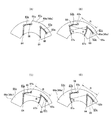
[Fifth Example of Reference Example]
A fifth example of the reference example relating to the present invention will be described with reference to FIGS. The torque transmission device-equipped rotation transmission device 5a of this embodiment includes a housing (a transmission case) (not shown), a hollow (hollow cylindrical) torque transmission shaft 6 functioning as an input shaft (or counter shaft), and a rolling bearing 7 , An output gear 8, one encoder 24 and one sensor unit 12.

前記エンコーダ24は、前記転がり軸受7を構成する内輪に支持固定される、磁性金属板から造られた断面クランク形で円環状の支持環25と、この支持環25の外周面に全周に亙り固定された、円環状で永久磁石製のエンコーダ本体26とから構成されている。このエンコーダ本体26の外周面には、S極とN極とが円周方向に関して交互に且つ等ピッチで配置されており、これらS極とN極との境界は、軸方向中央部が円周方向に関して最も突出した(又は凹んだ)V字形になっている。そして、被検出面である前記エンコーダ本体26の外周面のうち、幅方向片半部(図24、25の右半部、図26の下半部)を、円周方向に関する磁気特性変化の位相がこの外周面の幅方向に対して所定方向に漸次変化する第一被検出面27とし、幅方向他半部(図24、25の左半部、図26の上半部)を、円周方向に関する磁気特性変化の位相が前記外周面の幅方向に対して前記所定方向と逆方向に漸次変化する第二被検出面28としている。尚、図示は省略するが、エンコーダを、トルク伝達軸6の軸方向他端部に、直接外嵌固定する構造を採用する事もできる。   The encoder 24 is supported and fixed to the inner ring constituting the rolling bearing 7, and has an annular support ring 25 made of a magnetic metal plate and made of a magnetic metal plate, and the outer peripheral surface of the support ring 25 all around the circumference. It comprises a fixed, annular, permanent magnet encoder body 26. On the outer peripheral surface of the encoder main body 26, south poles and north poles are alternately arranged at equal pitches in the circumferential direction, and the boundary between these south poles and north poles has a circumferential center in the axial direction. It is V-shaped most projecting (or recessed) with respect to the direction. Then, of the outer peripheral surface of the encoder main body 26, which is the detected surface, the width direction one half (the right half in FIGS. 24 and 25, the lower half in FIG. 26) Is the first detection surface 27 gradually changing in a predetermined direction with respect to the width direction of the outer peripheral surface, and the other half in the width direction (the left half in FIGS. 24 and 25 and the upper half in FIG. The second detection surface 28 has a phase of the change of the magnetic characteristic with respect to the direction which gradually changes in the direction opposite to the predetermined direction with respect to the width direction of the outer peripheral surface. Although not shown, it is possible to adopt a structure in which the encoder is directly fixed to the other end of the torque transmission shaft 6 in the axial direction.

本参考例の場合には、前記トルク測定装置付回転伝達装置5a全体として、1個のエンコーダ24のみを用いており、このエンコーダ24に、前記第一被検出面27と前記第二被検出面28とを設けている。この為、前記トルク伝達軸6の内側には、前記参考例の第1〜4例の構造の様に、内軸9は設けていない。従って、図示は省略するが、トルク伝達軸を中実状とする事もできる。   In the case of this reference example, only one encoder 24 is used as a whole of the torque transmitting device-equipped rotation transmitting device 5a, and the encoder 24 includes the first detection surface 27 and the second detection surface. And 28 are provided. Therefore, the inner shaft 9 is not provided inside the torque transmission shaft 6 as in the first to fourth examples of the reference example. Therefore, although not shown, the torque transmission shaft can be made solid.

又、本参考例の場合にも、前記センサユニット12を構成するホルダ20を、前記トルク伝達軸6の軸方向他端寄り部分を回転自在に支持する転がり軸受7を構成する外輪に対して支持固定している。そして、この状態で、前記ホルダ20の先端部に包埋された第一、第二センサ21、22のうち、第一センサ21の第一検出部を、前記第一被検出面27に、前記第二センサ22の第二検出部を、前記第二被検出面28に、それぞれ近接対向させている。又、前記第一、第二両センサ21、22の検出部が、前記エンコーダ24の外周面に対向する位置は、このエンコーダ24の円周方向に関して同じ位置としている。言い換えれば、前記第一、第二両センサ21、22の検出部は、前記トルク伝達軸6の中心軸を含む同一仮想平面上に配置されている。尚、図示は省略するが、センサユニットを構成するホルダを、ハウジングに対して支持固定する事もできる。   Also in the case of the present embodiment, the holder 20 constituting the sensor unit 12 is supported by the outer ring constituting the rolling bearing 7 rotatably supporting a portion near the other end of the torque transmission shaft 6 in the axial direction. It is fixed. Then, in this state, of the first and second sensors 21 and 22 embedded in the front end portion of the holder 20, the first detection portion of the first sensor 21 is disposed on the first detection surface 27 as the first detection portion. The second detection portion of the second sensor 22 is closely opposed to the second detection surface 28. Further, the positions at which the detection portions of the first and second sensors 21 and 22 face the outer peripheral surface of the encoder 24 are the same in the circumferential direction of the encoder 24. In other words, the detection portions of the first and second sensors 21 and 22 are disposed on the same imaginary plane including the central axis of the torque transmission shaft 6. In addition, although illustration is abbreviate | omitted, the holder which comprises a sensor unit can also be supported and fixed with respect to a housing.

又、前記トルク伝達軸6に、アキシアル荷重(初期設定予圧に基づくアキシアル荷重も含む)が作用していない状態で、N極に着磁された部分とS極に着磁された部分との軸方向中間部で円周方向に関して最も突出した部分(境界の傾斜方向が変化する部分)が、前記第一、第二両センサ21、22の検出部同士の間の丁度中央位置に存在する様に、前記各部材21、22、24の設置位置を規制している。従って、この様な中立状態では、前記第一、第二両センサ21、22の検出部は、図7の(A)の実線イ、イ上、即ち、前記最も突出した部分から軸方向に同じだけずれた部分に対向する。従って、前記第一、第二両センサ21、22の出力信号の位相は、同図の(C)に示す様に一致する。   In addition, the shaft of a portion magnetized in the N pole and a portion magnetized in the S pole in a state where no axial load (including an axial load based on the initial setting preload) is acting on the torque transmission shaft 6 In the middle of the direction, the most projecting part in the circumferential direction (the part where the inclination direction of the boundary changes) is located just at the center between the detection parts of the first and second sensors 21 and 22. The installation positions of the respective members 21, 22, 24 are regulated. Therefore, in such a neutral state, the detection portions of the first and second sensors 21 and 22 are the same as in the solid line in FIG. It faces the part which only shifted. Therefore, the phases of the output signals of the first and second sensors 21 and 22 coincide with each other as shown in FIG.

又、前記トルク伝達軸6は、図示しないハウジングに対して、前記転がり軸受7により回転自在に支持されており、この転がり軸受7には予圧(初期設定予圧)が付与されている。この為、前記トルク伝達軸6は、この予圧の大きさに応じた分だけ、前記中立状態からアキシアル方向に僅かに変位する。又、前記トルク伝達軸6は、軸方向中間部に設けられたはすば歯車である出力歯車8と、図示しない相手歯車である別のはすば歯車との噛合部に作用する反力のうち、アキシアル方向の分力(アキシアル荷重)に基づき、アキシアル方向に変位する。従って、前記トルク伝達軸6に、この様な予圧やアキシアル荷重が作用した状態では、前記第一、第二両センサ21、22の検出部は、図7の(A)の実線イ、イ上から幅方向に関して同方向にずれ、破線ロ、ロ上、又は、鎖線ハ、ハ上に対向する。そして、この状態では、前記第一、第二両センサ21、22の出力信号の位相は、同図の(B)又は(D)に示す様にずれる。この様にして生じる第一、第二両センサ21、22の出力信号同士の間に存在する位相差(位相差比)は、前記噛合部に作用するアキシアル荷重に基づくアキシアル変位量と、前記予圧に基づくアキシアル変位量との合計に見合った値となる。従って、前記第一、第二両センサ21、22の出力信号同士の間に存在する位相差から、前記予圧に基づくアキシアル変位量分を差し引く(組み付け時に校正を行う)事で、前記トルク伝達軸6が伝達するトルクの大きさに見合った値である、前記噛合部に作用するアキシアル荷重に基づくアキシアル変位量を求められる。この結果、本参考例の場合には、図示しない演算器に予め記憶させておいた、前記位相差(位相差比)と、前記アキシアル変位量(アキシアル荷重)と、前記トルクとの関係を表す、式やマップを利用して、前記トルク伝達軸6が伝達するトルクの大きさを求める事ができる。尚、本参考例を実施する場合には、転がり軸受に予圧を付与した状態を中立状態として、トルク伝達軸が伝達するトルクを求める事もできる。   Further, the torque transmission shaft 6 is rotatably supported by the rolling bearing 7 with respect to a housing (not shown), and a preload (initial setting preload) is applied to the rolling bearing 7. Therefore, the torque transmission shaft 6 is slightly displaced in the axial direction from the neutral state by an amount corresponding to the magnitude of the preload. Further, the torque transmission shaft 6 has a reaction force acting on a meshing portion between an output gear 8 which is a helical gear provided at an axial intermediate portion and another helical gear which is a partner gear (not shown). Among them, it is displaced in the axial direction due to an axial component force (axial load). Therefore, in a state where such a preload or axial load is applied to the torque transmission shaft 6, the detection portions of the first and second sensors 21 and 22 are solid lines a and b in FIG. 7A. It deviates in the same direction with respect to the width direction, and faces a broken line b, a b above, or a dashed line c, b c above. In this state, the phases of the output signals of the first and second sensors 21 and 22 are shifted as shown in (B) or (D) of FIG. The phase difference (phase difference ratio) existing between the output signals of the first and second sensors 21 and 22 generated in this manner is the axial displacement amount based on the axial load acting on the meshing portion, and the preload Is a value commensurate with the sum of the amount of axial displacement based on. Therefore, the torque transmission shaft is obtained by subtracting the amount of axial displacement based on the preload from the phase difference existing between the output signals of the first and second sensors 21 and 22 (performing calibration at the time of assembly). An axial displacement amount based on an axial load acting on the meshing portion, which is a value commensurate with the magnitude of the torque transmitted by 6, can be obtained. As a result, in the case of the present embodiment, the relationship between the phase difference (phase difference ratio), the axial displacement amount (axial load), and the torque, which is stored in advance in a computing device not shown, is represented. The magnitude of the torque transmitted by the torque transmission shaft 6 can be determined by using an equation or a map. In addition, when implementing this reference example, it is also possible to obtain the torque transmitted by the torque transmission shaft with the state in which the preload is applied to the rolling bearing as the neutral state.

以上の様な構成を有する本参考例の場合には、前記トルク測定装置付回転伝達装置5a全体として、1個のエンコーダ24を使用するのみで、前記トルク伝達軸6が伝達するトルクの大きさ及び方向を求める事ができる。この為、部品点数の削減に伴うコストの低減を図れる。又、前記トルク伝達軸6の内径側に、内軸9(図1〜4参照)を配置しなくて済む為、このトルク伝達軸6の設計の自由度を向上できる。更には、このトルク伝達軸6の強度確保を図る面からも有利になる。
その他の構成及び作用効果に就いては、前述した参考例の第1例の場合と同様である。
In the case of the present embodiment having the above-described configuration, the magnitude of the torque transmitted by the torque transmission shaft 6 only by using one encoder 24 as the whole torque transmission device-equipped rotation transmitting device 5a. And you can ask for the direction. For this reason, the cost reduction accompanying reduction of a number of parts can be aimed at. Further, since it is not necessary to dispose the inner shaft 9 (see FIGS. 1 to 4) on the inner diameter side of the torque transmission shaft 6, the degree of freedom in design of the torque transmission shaft 6 can be improved. Furthermore, it is advantageous from the viewpoint of securing the strength of the torque transmission shaft 6.
The other configurations and effects are similar to those of the first example of the reference example described above.

[参考例の第6例]
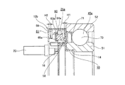
本発明に関する参考例の第6例に就いて、図27〜28を参照しつつ説明する。本参考例の場合には、転がり軸受7(図28では円すいころ軸受)を構成する内輪に、トルク検出用有孔部材である、トルク検出用スリーブ29を支持固定している。これに対し、内軸9の軸方向他端部に、トルク検出用凹凸部材30を支持固定している。尚、図示は省略するが、トルク検出用スリーブを、トルク伝達軸6の軸方向他端部に、直接外嵌固定する構造を採用する事もできる。
[Sixth Example of Reference Example]
A sixth example of the reference example relating to the present invention will be described with reference to FIGS. In the case of this reference example, a torque detection sleeve 29, which is a torque detection apertured member, is supported and fixed to the inner ring that constitutes the rolling bearing 7 (the tapered roller bearing in FIG. 28). On the other hand, at the other end in the axial direction of the inner shaft 9, a torque detection uneven member 30 is supported and fixed. Although not shown in the drawings, it is also possible to adopt a structure in which the torque detection sleeve is directly fitted on and fixed to the other axial end of the torque transmission shaft 6.

このうちのトルク検出用凹凸部材30は、鉄系合金等の磁性材製で、全体を円筒状に形成されており、軸方向中間部外周面に、外周面形状を円周方向に関する凹凸形状(歯車形状)とした、トルク検出用凹凸部31を設けている。尚、図28には、内軸9の外周面に直接、トルク検出用凹凸部31を形成した構造を示している。   Among them, the concavo-convex member 30 for torque detection is made of a magnetic material such as an iron-based alloy, and the whole is formed in a cylindrical shape. The torque detecting uneven portion 31 is provided in a gear shape. Note that FIG. 28 shows a structure in which the torque detection uneven portion 31 is formed directly on the outer peripheral surface of the inner shaft 9.

一方、前記トルク検出用スリーブ29は、アルミニウム合金等の導電性を有する非磁性金属板製で、全体を段付円筒状に形成されており、前記転がり軸受7を構成する内輪に支持固定された大径筒部32と、小径筒部33とを有する。このうちの小径筒部33は、前記トルク検出用凹凸部31(第二被検出部)の外径側に、このトルク検出用凹凸部31と径方向に近接した状態で同心に配置されている。又、この状態で、前記小径筒部33は、前記トルク検出用凹凸部材30と後述するコイルセンサユニット34との間部分に位置している。又、前記小径筒部33には、複数の略矩形の貫通孔である窓孔35、35が、軸方向に複列に、且つ、円周方向に関して等間隔に設けられており、これら両列の窓孔35、35の円周方向位相は、互いに半ピッチずれている。   On the other hand, the torque detection sleeve 29 is made of a nonmagnetic metal plate having conductivity such as aluminum alloy, and the whole is formed in a stepped cylindrical shape, and is supported and fixed to the inner ring constituting the rolling bearing 7 It has a large diameter cylindrical portion 32 and a small diameter cylindrical portion 33. Among them, the small diameter cylindrical portion 33 is concentrically disposed on the outer diameter side of the torque detecting uneven portion 31 (second detected portion) in a state of being radially close to the torque detecting uneven portion 31. . Further, in this state, the small diameter cylindrical portion 33 is located at a portion between the torque detecting concave-convex member 30 and the coil sensor unit 34 described later. Further, in the small diameter cylindrical portion 33, window holes 35, 35, which are a plurality of substantially rectangular through holes, are provided in double rows in the axial direction and at equal intervals in the circumferential direction. The circumferential phases of the window holes 35, 35 are shifted by half pitch from each other.

又、前記転がり軸受7を構成する外輪に対し、断面L字形で全体を円環状とした支持部材36を利用して、コイルセンサユニット34を支持固定している。このコイルセンサユニット34は、前記トルク検出用凹凸部31及び前記トルク検出用スリーブ29の小径筒部33の外径側に同心に配置されている。又、前記コイルセンサユニット34は、円筒状の検出本体37と、この検出本体37の外周面から径方向外方に突出する状態で設けられた、図示しない樹脂製の台座と、この台座に植設された、図示しない複数本(例えば4本)の金属製のピンから成る接続端子とを備える。前記検出本体37は、それぞれが円環状のコイルボビンに巻回された複数(図示の例では2つ)のコイル38、38と、これら各コイルボビンに巻回されたコイル38、38を覆った金属製のヨーク部材39とから成る。前記接続端子は、前記検出本体37の円周方向の一部に径方向外方に突出する状態で設けられており、前記各コイル38、38に接続されている。又、前記接続端子は、図示しない回路基板に接続され、1本のハーネス23を通じて、前記コイルセンサユニット34の出力信号を演算器に送信する。尚、図示は省略するが、コイルセンサユニットを、ハウジングに対して支持固定する事もできる。   Further, the coil sensor unit 34 is supported and fixed to the outer ring constituting the rolling bearing 7 by using a support member 36 which is L-shaped in cross section and has an annular shape as a whole. The coil sensor unit 34 is concentrically disposed on the outer diameter side of the uneven portion 31 for detecting torque and the small diameter cylindrical portion 33 of the sleeve 29 for detecting torque. The coil sensor unit 34 includes a cylindrical detection main body 37, a resin pedestal (not shown) provided so as to project radially outward from the outer peripheral surface of the detection main body 37, and And a connection terminal composed of a plurality of (for example, 4) metal pins (not shown). The detection body 37 is made of a plurality of (two in the illustrated example) coils 38 wound around an annular coil bobbin and a metal 38 covering the coils 38 wound around the respective coil bobbins. And the yoke member 39 of FIG. The connection terminal is provided so as to project radially outward in a part of the detection main body 37 in the circumferential direction, and is connected to the coils 38, 38. Further, the connection terminal is connected to a circuit board (not shown), and transmits an output signal of the coil sensor unit 34 to a computing unit through one harness 23. Although not shown, the coil sensor unit can be supported and fixed to the housing.

上述の様な構成を有する本参考例のトルク測定装置付回転伝達装置5bの場合にも、前記トルク伝達軸6によりトルクが伝達されると、このトルクの方向及び大きさに応じた分だけ、このトルク伝達軸6の軸方向一端部に前記内軸9を介して間接的に取り付けられた前記トルク検出用凹凸部材30のトルク検出用凹凸部31と、前記トルク伝達軸6の軸方向他端寄り部分に前記内輪を介して間接的に取り付けられた前記トルク検出用スリーブ29の小径筒部33との、円周方向に関する位置関係が変化する。そして、この位置関係の変化に応じた分だけ、前記コイルセンサユニット34を構成するコイル38、38のインピーダンスに変化が生じる。従って、このインピーダンス変化に基づいて、前記トルクの方向及び大きさを検出できる。
その他の構成及び作用効果に就いては、前述した参考例の第1例の場合と同様である。
Also in the case of the rotation transmitting device 5b with a torque measuring device of the present embodiment having the configuration as described above, when torque is transmitted by the torque transmitting shaft 6, an amount corresponding to the direction and magnitude of this torque The torque detecting uneven portion 31 of the torque detecting uneven member 30 indirectly attached to one end in the axial direction of the torque transmitting shaft 6 via the inner shaft 9 and the other end in the axial direction of the torque transmitting shaft 6 The positional relationship in the circumferential direction changes with the small diameter cylindrical portion 33 of the torque detection sleeve 29 indirectly attached to the offset portion via the inner ring. Then, the impedance of the coils 38, 38 constituting the coil sensor unit 34 is changed by an amount corresponding to the change in the positional relationship. Therefore, based on this change in impedance, the direction and magnitude of the torque can be detected.
The other configurations and effects are similar to those of the first example of the reference example described above.

[参考例の第7例]
本発明に関する参考例の第7例に就いて、図29を参照しつつ説明する。本参考例の特徴は、トルク伝達軸6を、図示しないハウジングに対して、1対の転がり軸受7、40により回転自在に支持し、前記トルク伝達軸6を両持ち梁式の支持構造とした点にある。即ち、本参考例の場合には、前記トルク伝達軸6の軸方向中間部のうち、軸方向一端部に設けられたスプライン部13と出力歯車8が固定された部分との間部分を、第二の転がり軸受40により回転自在に支持している。この第二の転がり軸受40としては、深溝型、アンギュラ型等の玉軸受、円すいころ軸受、円筒ころ軸受、ラジアルニードル軸受等を採用可能である。又、本参考例の場合には、前記1対の転がり軸受7、40同士で、互いの接触角を逆向きとしている。この様な構成を有する本参考例の場合には、前記トルク伝達軸6の支持剛性を高める事ができる。
その他の構成及び作用効果に就いては、前記参考例の第1例の場合と同様である。
[Seventh example of reference example]
A seventh example of the reference example relating to the present invention will be described with reference to FIG. A feature of the present embodiment is that the torque transmission shaft 6 is rotatably supported by a pair of rolling bearings 7 and 40 with respect to a housing (not shown), and the torque transmission shaft 6 has a double support type support structure It is on the point. That is, in the case of the present embodiment, a portion between the spline portion 13 provided at one end in the axial direction and the portion to which the output gear 8 is fixed in the axially intermediate portion of the torque transmission shaft 6 It is rotatably supported by the second rolling bearing 40. As the second rolling bearing 40, a ball bearing such as a deep groove type or an angular type, a tapered roller bearing, a cylindrical roller bearing, a radial needle bearing or the like can be adopted. Further, in the case of the present embodiment, the contact angles of the pair of rolling bearings 7 and 40 are opposite to each other. In the case of the present embodiment having such a configuration, the support rigidity of the torque transmission shaft 6 can be enhanced.
The other configurations and effects are similar to those of the first example of the reference example.

[参考例の第8例]
本発明に関する参考例の第8例に就いて、図30を参照しつつ説明する。本参考例の特徴は、トルク伝達軸6aをカウンタシャフトとして、このトルク伝達軸6aの軸方向中間部で、1対の転がり軸受7、40同士の間部分に、2個の出力歯車8a、8bを固定している(トルク伝達軸6aと一体に設けている)点にある。又、本参考例の場合、これら両歯車8a、8bの外周面に形成された歯数を、自動変速機の段数に応じて、互いに異ならせている。尚、出力歯車は、トルク伝達軸に対して一体的に設けても良いし、結合固定しても良い。
その他の構成及び作用効果に就いては、前記参考例の第1例及び第7例の場合と同じである。
[The eighth example of the reference example]
An eighth embodiment of the present invention will be described with reference to FIG. A feature of the present embodiment is that, with the torque transmission shaft 6a as a counter shaft, two output gears 8a and 8b are provided in the axially intermediate portion of the torque transmission shaft 6a and between the pair of rolling bearings 7 and 40. Is fixed (provided integrally with the torque transmission shaft 6a). Further, in the case of the present embodiment, the numbers of teeth formed on the outer peripheral surfaces of both the gears 8a and 8b are made different from each other according to the number of stages of the automatic transmission. The output gear may be integrally provided to the torque transmission shaft, or may be coupled and fixed.
The other configurations and effects are the same as those of the first and seventh examples of the reference example.

[参考例の第9例]
本発明に関する参考例の第9例に就いて、図31を参照しつつ説明する。本参考例の特徴は、トルク伝達軸6bの軸方向他端寄り部分の内周面に、その他の部分よりも内径寸法が小さくなった案内面42を形成している。又、前記トルク伝達軸6bの内径側に配置された内軸9aの軸方向中間部他端寄り部分で、径方向に関して前記案内面42と対向する部分に、軸方向一端部に設けた大径部41よりは外径寸法が小さいが、その他の部分よりは外径寸法が大きくなった被案内面43を形成している。そして、本参考例の場合には、前記案内面42とこの被案内面43とを隙間を介して径方向に近接対向させて、この被案内面43をこの案内面42によって案内支持している。尚、前記隙間の大きさは、小さい程好ましく、例えば100μm以下とする事が好ましく、更に嵌めあい公差で、例えばH7/g6又はH7/g7とする事が好ましい。
[The ninth example of the reference example]
A ninth example of the reference example according to the present invention will be described with reference to FIG. A feature of the present embodiment is that a guide surface 42 whose inside diameter is smaller than the other portions is formed on the inner peripheral surface of the portion near the other end in the axial direction of the torque transmission shaft 6b. Also, a large diameter provided at one end in the axial direction at a portion facing the guide surface 42 in the radial direction at a portion near the other end in the axial direction of the inner shaft 9a disposed on the inner diameter side of the torque transmission shaft 6b. Although the outside diameter size is smaller than the part 41, the to-be-guided surface 43 which the outside diameter size became larger than the other part is formed. Further, in the case of the present reference example, the guide surface 42 and the guided surface 43 are closely opposed in the radial direction via a gap, and the guided surface 43 is guided and supported by the guiding surface 42. . The size of the gap is preferably as small as possible, for example, preferably 100 μm or less, and the fitting tolerance is further preferably H7 / g6 or H7 / g7.

以上の様な構成を有する本参考例の場合には、前記内軸9aを、軸方向一端部に設けた大径部41と、軸方向中間部他端寄り部分に設けた前記被案内面43とにより、前記トルク伝達軸6bに対して軸方向に離隔した2個所で支持する事ができる(両持ち梁式の支持構造を採用できる)。この為、前記トルク伝達軸6bの回転振動が大きくなる領域(高トルク、高速回転域)であっても、前述した参考例の第1例の構造の様に、大径部41による1個所のみで支持する構造(片持ち式の支持構造)を採用した場合に比べて、前記内軸9aの回転振れを抑える事ができる。従って、この内軸9aの軸方向他端部に固定した第二エンコーダ11の振れを抑える事ができる。この結果、本参考例の構造によれば、この第二エンコーダ11の振れに基づき、トルクの測定性能が低下する事を防止できる。
その他の構成及び作用効果に就いては、前記参考例の第1例の場合と同じである。
In the case of the present embodiment having the above-described configuration, the inner shaft 9a is provided with the large diameter portion 41 provided at one end in the axial direction and the guided surface 43 provided at the other end near the other end in the axial direction. , And can be supported at two points axially separated from the torque transmission shaft 6b (a double-supported beam type support structure can be adopted). For this reason, even in the region (high torque, high speed rotation region) where the rotational vibration of the torque transmission shaft 6b becomes large, as in the structure of the first example of the reference example described above, only one place by the large diameter portion 41 As compared with the case of adopting the structure (cantilevered support structure) supported by the above, the rotational runout of the inner shaft 9a can be suppressed. Therefore, the shake of the second encoder 11 fixed to the other axial end of the inner shaft 9a can be suppressed. As a result, according to the structure of the present embodiment, it is possible to prevent the reduction of the torque measurement performance based on the deflection of the second encoder 11.
The other configurations and effects are the same as in the first example of the reference example.

[参考例の第10例]
本発明に関する参考例の第10例に就いて、図32を参照しつつ説明する。本参考例の場合には、内軸9bの軸方向中間部他端寄り部分の外周面に形成された被案内面43aに、摩耗を防止する為の表面処理を施している。より具体的には、炭素鋼製の前記内軸9bに、焼入れ、焼戻し処理を施して、その硬度をHRC30〜50に規制し、その後、前記被案内面43aに、以下の(1)〜(6)の中から選択される表面処理を施している。
(1)二硫化モリブデン、二硫化タングステン、PTFE等の固体潤滑膜(デフリックコート)を、例えば固体潤滑剤の粒子を噴射して堆積させるショットピーニング加工により形成する。
(2)ダイヤモンドライクカーボン(DLC)を、プラズマCVD法やスパッタリング法などにより形成する。
(3)金、銅、銀、亜鉛、鉛、錫、チタン、ニッケル、アルミニウム等の金属皮膜(例えば10μm以下の膜)を、例えばショットピーニング加工又はメッキにより形成する。
(4)リン酸マンガン、リン酸亜鉛又はリン酸亜鉛カルシウム等のリン酸塩処理を施し、化成処理膜を形成する。
(5)四三酸化鉄被膜処理(黒染め処理)により酸化被膜を形成する。
(6)硬質クロムメッキ、ニッケル亜鉛メッキ、無電解ニッケルメッキなどの硬質皮膜を形成する。
又、本例の場合には、上述の様な(1)〜(6)の中から選択される表面処理を施した後、前記被案内面43aに潤滑油やグリース等の潤滑剤を塗布している。
[Tenth example of reference example]
A tenth example of the reference to the present invention will be described with reference to FIG. In the case of this reference example, a surface treatment for preventing wear is applied to the guided surface 43a formed on the outer peripheral surface of the portion near the other end in the axial direction of the inner shaft 9b. More specifically, the inner steel shaft 9b made of carbon steel is subjected to quenching and tempering treatment to restrict its hardness to HRC 30 to 50, and then, the following (1) to (1) to (4) The surface treatment selected from 6) is applied.
(1) A solid lubricating film (deferic coat) such as molybdenum disulfide, tungsten disulfide, or PTFE is formed, for example, by shot peening in which particles of the solid lubricant are sprayed and deposited.
(2) Diamond like carbon (DLC) is formed by plasma CVD method, sputtering method or the like.
(3) A metal film (for example, a film of 10 μm or less) such as gold, copper, silver, zinc, lead, tin, titanium, nickel, or aluminum is formed by, for example, shot peening or plating.
(4) Phosphate treatment with manganese phosphate, zinc phosphate or zinc calcium phosphate is performed to form a chemical conversion film.
(5) An oxide film is formed by triiron trioxide coating treatment (black dyeing treatment).
(6) Hard coatings such as hard chrome plating, nickel zinc plating, electroless nickel plating are formed.
Further, in the case of this example, after performing the surface treatment selected from among (1) to (6) as described above, a lubricant such as lubricating oil or grease is applied to the guided surface 43a. ing.

以上の様な構成を有する本参考例の場合には、前記被案内面43aに、トルク伝達軸6bの内周面に形成された案内面42との擦れ合いに伴って、過度の摩耗が生じる事を有効に防止できる。この為、発生した摩耗粉が歯車同士の噛合部や転がり接触部等に侵入して、各部の寿命を低下させる事を有効に防止できる。
その他の構成及び効果に就いては、前記参考例の第1例及び第9例の場合と同じである。
In the case of the present embodiment having the above-described configuration, excessive abrasion occurs in the guided surface 43a due to the friction with the guide surface 42 formed on the inner peripheral surface of the torque transmission shaft 6b. You can prevent things effectively. For this reason, it is possible to effectively prevent the wear powder generated from intruding into the meshing portion, the rolling contact portion, etc. of the gears to reduce the life of each portion.
The other configurations and effects are the same as in the first and ninth examples of the reference example.

[参考例の第11例]
本発明に関する参考例の第11例に就いて、図33を参照しつつ説明する。本参考例の場合には、トルク伝達軸6bの内周面に形成された案内面42と、内軸9aの外周面に形成した被案内面43との間に、これらトルク伝達軸6b及び内軸9aとは別体の、環状のブッシュ91を介在させている。このブッシュ91としては、例えば滑り軸受やラジアルニードル軸受を採用する事ができる。
[The eleventh example of the reference example]
An eleventh example of the reference example relating to the present invention will be described with reference to FIG. In the case of the present embodiment, the torque transmission shaft 6b and the inner surface of the torque transmission shaft 6b are formed between the guide surface 42 formed on the inner peripheral surface of the torque transmission shaft 6b and the guided surface 43 formed on the outer peripheral surface of the inner shaft 9a. An annular bush 91 separate from the shaft 9a is interposed. As the bush 91, for example, a slide bearing or a radial needle bearing can be employed.

以上の様な構成を有する本参考例の場合には、前記案内面42と前記被案内面43とが直接擦れ合う事がない為、これら両面42、43が摩耗する事に起因した摩耗粉が発生する事を防止できる。又、これら両面42、43に、仕上処理を施したり、摩耗防止の為の表面処理を施す必要がなくなる為、装置の加工コストを抑える事もできる。
その他の構成及び効果に就いては、前記参考例の第1例及び第9例の場合と同じである。
In the case of the present embodiment having the above-described configuration, since the guide surface 42 and the guided surface 43 do not directly rub against each other, wear powder is generated due to the wear of the both surfaces 42 and 43. It can prevent doing. Further, since there is no need to finish the both surfaces 42 and 43 or to perform surface treatment for preventing wear, it is possible to reduce the processing cost of the apparatus.
The other configurations and effects are the same as in the first and ninth examples of the reference example.

[参考例の第12例]
本発明に関する参考例の第12例に就いて、図34を参照しつつ説明する。本参考例の場合には、前述した実施の形態の各例の構造と同様に(上述した参考例の各例の構造とは異なり)、トルク伝達軸6cにトルクを伝達する動力源が、このトルク伝達軸6cと同軸上に配置されない構造の1例を示している。この様な本参考例の場合、このトルク伝達軸6cにトルクを入力する為の入力歯車44を、このトルク伝達軸6cの軸方向中間部に、このトルク伝達軸6cと一体に設けており、トルクを出力する為の出力歯車8cを、このトルク伝達軸6cの軸方向一端寄り部分に、このトルク伝達軸6cと一体に設けている。尚、前記入力歯車44及び前記出力歯車8cとしては、平歯車やはすば歯車を採用できる。又、本参考例の場合には、前記トルク伝達軸6cのうち、前記入力歯車44及び前記出力歯車8cが設置された部分を挟んだ両側部分(軸方向他端寄り部分及び軸方向一端部)を、1対の転がり軸受45a、45bにより、図示しないハウジングに対し回転自在に支持している。尚、この様な構成を有する本参考例の構造は、ディファレンシャルギヤを持つ軸と対になる軸である、例えばカウンタ軸に適用できる。
前記トルク伝達軸6cに関するトルクの入力部及び出力部、並びに、このトルク伝達軸6cの支持構造が異なる以外の構成及び得られる作用効果に就いては、前記参考例の第1例及び第9例の場合と同様である。
[The 12th example of the reference example]
A twelfth example of the reference example according to the present invention will be described with reference to FIG. In the case of this reference example, the power source for transmitting torque to the torque transmission shaft 6c is the same as the structure of each example of the embodiment described above (different from the structure of each example of the reference example described above). An example of the structure which is not coaxially arranged with the torque transmission shaft 6c is shown. In the case of the present embodiment, an input gear 44 for inputting a torque to the torque transmission shaft 6c is provided integrally with the torque transmission shaft 6c at an axially intermediate portion of the torque transmission shaft 6c. An output gear 8c for outputting a torque is provided integrally with the torque transmission shaft 6c at a portion near one end in the axial direction of the torque transmission shaft 6c. As the input gear 44 and the output gear 8c, a spur gear or a helical gear can be employed. Further, in the case of the present embodiment, both side portions (portion close to the other end in the axial direction and one end portion in the axial direction) of the torque transmission shaft 6c sandwiching the portion where the input gear 44 and the output gear 8c are installed. Is rotatably supported by a pair of rolling bearings 45a and 45b with respect to a housing (not shown). The structure of the present embodiment having such a configuration can be applied to, for example, a counter shaft which is a shaft paired with a shaft having a differential gear.
With respect to the configuration and effect obtained except for the torque input part and output part related to the torque transmission shaft 6c and the support structure of the torque transmission shaft 6c, the first example and the ninth example of the reference example The same as in the case of.

[参考例の第13例]
本発明に関する参考例の第13例に就いて、図35を参照しつつ説明する。本参考例の場合には、上述した参考例の第12例の構造と同様に、トルク伝達軸6dにトルクを入力する為の入力歯車44を、このトルク伝達軸6dの軸方向中間部に、このトルク伝達軸6dと一体又は別体に設けると共に、このトルク伝達軸6dからトルクを出力する為の出力歯車8cを、このトルク伝達軸6dの軸方向一端寄り部分に、このトルク伝達軸6dと一体又は別体に設けている。そして、特に本参考例の場合には、この様なトルク伝達軸6dをハウジングに対して回転自在に支持する為の1対の転がり軸受45a、45cの配置を、上述した参考例の第12例の構造の場合とは異ならせている。即ち、本参考例の場合には、前記トルク伝達軸6dのうち、前記出力歯車8cが設置された部分よりも軸方向一端側ではなく、この出力歯車8cが設置された部分よりも軸方向中央寄り部分を、前記転がり軸受45cにより支持している。これにより、前記入力歯車44を軸方向両側から挟む様に、前記両転がり軸受45a、45cを配置している。尚、前記入力歯車44及び前記出力歯車8cとしては、平歯車、はすば歯車、かさ歯車又はハイポイドギヤを採用できる。
以上の様に、前記トルク伝達軸6dを回転自在に支持する為の支持構造が異なると共に、本参考例の構造では案内面と被案内面とを設ける構造(両持ち梁式の支持構造)を採用していない点を除き、上述した参考例の第12例の場合と同様である。
[The 13th example of the reference example]
A thirteenth example of the reference example relating to the present invention will be described with reference to FIG. In the case of the present reference example, as in the structure of the twelfth example of the reference example described above, an input gear 44 for inputting a torque to the torque transmission shaft 6d is provided at an axially intermediate portion of the torque transmission shaft 6d. An output gear 8c for outputting a torque from the torque transmission shaft 6d is provided integrally with or separately from the torque transmission shaft 6d in a portion near one end in the axial direction of the torque transmission shaft 6d with the torque transmission shaft 6d It is provided integrally or separately. In the case of the present embodiment in particular, the arrangement of the pair of rolling bearings 45a and 45c for rotatably supporting the torque transmission shaft 6d with respect to the housing is the twelfth embodiment of the above-described embodiment. It differs from the case of the structure of. That is, in the case of the present embodiment, the torque transmission shaft 6d is not axially one end side of the portion where the output gear 8c is installed, but is axially central more than the portion where the output gear 8c is installed. The inclined portion is supported by the rolling bearing 45c. Thus, the two rolling bearings 45 a and 45 c are disposed so as to sandwich the input gear 44 from both sides in the axial direction. As the input gear 44 and the output gear 8c, a spur gear, a helical gear, a bevel gear, or a hypoid gear can be employed.
As described above, the support structure for rotatably supporting the torque transmission shaft 6d is different, and in the structure of the present embodiment, a structure (double support beam type support structure) in which the guide surface and the guided surface are provided Except the point which is not employ | adopted, it is the same as that of the case of the 12th example of the reference example mentioned above.

[参考例の第14例]
本発明に関する参考例の第14例に就いて、図36を参照しつつ説明する。本参考例の場合には、上述した参考例の第13例の構造と同様に、トルク伝達軸6dにトルクを入力する為の入力歯車44を、このトルク伝達軸6dの軸方向中間部に、このトルク伝達軸6dと一体又は別体に設けると共に、このトルク伝達軸6dからトルクを出力する為の出力歯車8cを、このトルク伝達軸6dの軸方向一端寄り部分に、このトルク伝達軸6dと一体又は別体に設けている。そして、特に本参考例の場合には、この様なトルク伝達軸6dをハウジングに対して回転自在に支持する為に、3個の転がり軸受45a、45c、45dを使用している。即ち、本参考例の場合には、前記参考例の第13例の構造と同様の位置を回転自在に支持する2個の転がり軸受45a、45cに加えて、前記トルク伝達軸6dのうち、前記入力歯車44が設置された部分の軸方向一端側に隣接した部分を、前記転がり軸受45dにより支持している。
その他の構成及び作用効果に就いては、上述した参考例の第13例の場合と同様である。
[The 14th example of the reference example]
A fourteenth example of the reference to the present invention will be described with reference to FIG. In the case of the present reference example, as in the structure of the thirteenth example of the reference example described above, an input gear 44 for inputting a torque to the torque transmission shaft 6d is provided at an axially intermediate portion of the torque transmission shaft 6d. An output gear 8c for outputting a torque from the torque transmission shaft 6d is provided integrally with or separately from the torque transmission shaft 6d in a portion near one end in the axial direction of the torque transmission shaft 6d with the torque transmission shaft 6d It is provided integrally or separately. In the case of the present embodiment in particular, three rolling bearings 45a, 45c, 45d are used to rotatably support such a torque transmission shaft 6d with respect to the housing. That is, in the case of the present embodiment, in addition to the two rolling bearings 45a and 45c rotatably supporting the same position as the structure of the thirteenth embodiment of the above-mentioned embodiment, among the torque transmission shafts 6d, The rolling bearing 45 d supports a portion adjacent to one end side in the axial direction of the portion where the input gear 44 is installed.
The other configurations and effects are the same as in the thirteenth example of the reference example described above.

[参考例の第15例]
本発明に関する参考例の第15例に就いて、図37を参照しつつ説明する。本参考例は、前述した参考例の第12例の変形例である。即ち、この第12例の場合には、トルク伝達軸6cの軸方向中間部に入力歯車44を設けていたのに対し、本参考例の場合には、トルク伝達軸6cの軸方向中間部に、ベルト式の入力プーリ46を固設している。又、この様なトルク伝達軸6cの軸方向両端部を、図示しないハウジングに対して、1対の転がり軸受45a、45bにより回転自在に支持している。そして、図示しないハウジングに対し1対の転がり軸受47a、47bにより回転自在に支持され、前記トルク伝達軸6cと平行に配置された中間軸48の軸方向中間部に固定された出力プーリ49と、前記入力プーリ46との間に、ベルト50を掛け渡している。
以上の様に、トルクを入力する為の入力部の構造が異なる以外の構造及び得られる作用効果に就いては、前記参考例の第12例の場合と同様である。
尚、前記各プーリ46、49は、ベルト式無段変速機を構成するプーリとする事もできる。
[Fifteenth Example of Reference Example]
A fifteenth embodiment of the present invention will be described with reference to FIG. The present reference example is a modification of the twelfth example of the reference example described above. That is, in the case of the twelfth example, the input gear 44 is provided at the axially intermediate portion of the torque transmission shaft 6c, while in the case of this reference example, it is disposed at the axially intermediate portion of the torque transmission shaft 6c. The belt type input pulley 46 is fixed. Further, both axial ends of such a torque transmission shaft 6c are rotatably supported by a pair of rolling bearings 45a and 45b with respect to a housing (not shown). Then, an output pulley 49 rotatably supported by a pair of rolling bearings 47a and 47b with respect to a housing (not shown) and fixed to an axially intermediate portion of the intermediate shaft 48 disposed parallel to the torque transmission shaft 6c; A belt 50 is stretched between the input pulley 46 and the belt.
As described above, the structure other than the structure of the input unit for inputting the torque is different, and the obtained operational effects are the same as those of the twelfth example of the reference example.
The pulleys 46 and 49 may be pulleys constituting a belt type continuously variable transmission.

本発明のトルク測定装置付回転伝達装置を構成するトルク伝達軸は、自動車のパワートレインを構成する回転軸に限らず、例えば、風車の回転軸(主軸、増速器の回転軸)、圧延機のロールネック、鉄道車両の回転軸(車軸、減速機の回転軸)、工作機械の回転軸(主軸、送り系の回転軸)、建設機械・農業機械・家庭用電気器具・モータの回転軸等、各種機械装置の回転軸を対象にする事ができる。又、自動車のパワートレインを構成する場合には、例えば、トルクコンバータからトルクが入力されるインプットシャフト(タービンシャフト)や、カウンタシャフトを対象とする事ができる。又、本発明のトルク測定装置付回転伝達装置を組み込んで変速機を構成する場合の変速機の形式は、特に限定されず、オートマチックトランスミッション(AT)、ベルト式やトロイダル式等の各種無段変速機(CVT)、オートメーテッドマニュアルトランスミッション(AMT)、デュアルクラッチトランスミッション(DCT)、トランスファー等、車側の制御により変速を行う変速機を採用できる。又、変速機の設置位置と駆動輪との関係は特に限定されず、前置エンジン前輪駆動車(FF車)、前置エンジン後輪駆動車(FR車)、及び、四輪駆動車等が対象となる。又、測定した回転速度及びトルクは、変速制御やエンジンの出力制御以外の車両制御を行う為に利用しても良い。又、前記変速機の上流側に置かれる動力源は、必ずしもガソリンエンジンやディーゼルエンジン等の内燃機関である必要はなく、例えばハイブリッド車や電気自動車に用いられる電動モータであっても良い。又、本発明を実施する場合に、トルクを測定する事は必須であるが、回転速度を測定する事は必須ではない。回転速度が必要であっても、別途簡易な構造により測定する事もできる。更に、上述した実施の形態及び参考例では、エンコーダを永久磁石製とすると共に、エンコーダの被検出面にN極とS極とを、円周方向に関して交互に配置する構成を採用した構造を例に説明したが、エンコーダを単なる磁性材製とすると共に、このエンコーダの被検出面に凸部、舌片、又は柱部等の充実部と、凹部、切り欠き、又は透孔等の除肉部とを、円周方向に関して交互に配置する構成を採用する事もできる。この様な構成を採用する場合には、センサ側に永久磁石を組み込む。更に、前述した実施の形態の各例及び参考例の構造は、適宜組み合わせて実施する事ができる。例えば実施の形態の各例に示したセンサ構造を、参考例に示した各種構造に適用する事ができる。又、案内面と被案内面とを設ける構造(両持ち梁式の支持構造)は、トルク伝達軸の内径側に片持ち式に内軸を支持する構造を採用した、その他の実施の形態の各例及び参考例の構造に適用する事ができる。又、前述した参考例の第7〜15例では、センサ装置及び特性変化部材として、センサユニット12及び第一、第二エンコーダ10、11を採用し、参考例の第1例と同様の取付態様を採用しているが、これらに代えて、参考例の第2〜6例と同様の構成を採用する事もできる。又、実施の形態の各例では、トルク伝達軸を回転自在に支持する為の転がり軸受として玉軸受を使用した場合に就いて説明したが、本発明を実施する場合には、深溝玉軸受、円すいころ軸受、ニードル軸受、円筒ころ軸受、アンギュラ玉軸受等、従来から知られた各種構造の転がり軸受を使用できる。   The torque transmission shaft that constitutes the rotation transmission device with a torque measurement device of the present invention is not limited to the rotation shaft that constitutes the powertrain of an automobile, and, for example, the rotation shaft of a wind turbine (spindle, rotation shaft of speed increaser), rolling mill Roll neck, axis of rotation of railway vehicle (axle, axis of rotation of reduction gear), axis of rotation of machine tool (spindle, axis of rotation of feed system), axis of rotation of construction machine, agricultural machine, household appliance, motor etc , The rotational axis of various mechanical devices can be targeted. In addition, when configuring a power train of a car, for example, an input shaft (turbine shaft) to which torque is input from a torque converter, or a countershaft can be used. Further, the type of transmission in the case of constituting a transmission by incorporating the rotation transmitting device with a torque measuring device of the present invention is not particularly limited, and various continuously variable transmissions such as automatic transmission (AT), belt type and toroidal type It is possible to employ a transmission that performs gear shifting under vehicle control, such as a CVT, automated manual transmission (AMT), dual clutch transmission (DCT), and transfer. Also, the relationship between the installation position of the transmission and the drive wheels is not particularly limited, and front-end front-wheel drive cars (FF cars), front-engine rear-wheel drive cars (FR cars), four-wheel drive cars, etc. It becomes an object. The measured rotational speed and torque may be used to perform vehicle control other than shift control and engine output control. Further, the power source located on the upstream side of the transmission need not necessarily be an internal combustion engine such as a gasoline engine or a diesel engine, and may be, for example, an electric motor used in a hybrid vehicle or an electric vehicle. Moreover, when implementing this invention, it is essential to measure a torque, but it is not essential to measure a rotational speed. Even if the rotational speed is required, it can be measured by a simple structure separately. Furthermore, in the embodiment and the reference example described above, a structure is adopted in which the encoder is made of a permanent magnet, and a configuration in which the N pole and the S pole are alternately arranged in the circumferential direction on the detected surface of the encoder The encoder is made of a simple magnetic material, and the detection surface of the encoder has a solid portion such as a convex portion, a tongue or a pillar portion, and a non-walled portion such as a concave portion, a notch or a through hole. And may be alternately arranged in the circumferential direction. When adopting such a configuration, a permanent magnet is incorporated on the sensor side. Furthermore, the structure of each example and reference example of the embodiment described above can be implemented in combination as appropriate. For example, the sensor structure shown in each example of the embodiment can be applied to various structures shown in the reference example. Further, the structure for providing the guide surface and the guided surface (double support beam type support structure) is a structure in which the inner shaft is supported in a cantilever manner on the inner diameter side of the torque transmission shaft. It can apply to the structure of each example and a reference example. Further, in the seventh to fifteenth examples of the reference example described above, the sensor unit 12 and the first and second encoders 10 and 11 are adopted as the sensor device and the characteristic changing member, and the attachment aspect similar to the first example of the reference example However, in place of these, it is possible to adopt the same configuration as the second to sixth examples of the reference example. In each example of the embodiment, a ball bearing is used as a rolling bearing for rotatably supporting a torque transmission shaft, but in the case of practicing the present invention, a deep groove ball bearing, It is possible to use rolling bearings of various structures conventionally known, such as tapered roller bearings, needle bearings, cylindrical roller bearings, angular contact ball bearings, and the like.

1 回転軸
2 エンコーダ
3 センサ
4 ハーネス
5、5a トルク測定装置付回転伝達装置
6、6a、6b、6c、6d、6e トルク伝達軸
7 転がり軸受
8、8a、8b、8c、8d 出力歯車
9、9a、9b、9c 内軸
10、10a 第一エンコーダ
11 第二エンコーダ
12、12a、12b、12c、12d センサユニット
13 スプライン部
14、14a 支持環
15 支持環
16 エンコーダ本体
17 エンコーダ本体
18 第一被検出面
19 第二被検出面
20、20a ホルダ
21 第一センサ
22 第二センサ
23 ハーネス
24 エンコーダ
25 支持環
26 エンコーダ本体
27 第一被検出面
28 第二被検出面
29 トルク検出用スリーブ
30 トルク検出用凹凸部材
31 トルク検出用凹凸部
32 大径筒部
33 小径筒部
34 コイルセンサユニット
35 窓孔
36 支持部材
37 検出本体
38 コイル
39 ヨーク部材
40 転がり軸受
41 大径部
42 案内面
43、43a 被案内面
44、44a 入力歯車
45a、45b、45c、45d 転がり軸受
46 入力プーリ
47a、47b 転がり軸受
48 中間軸
49 出力プーリ
50 ベルト
51、51a 内輪
52、52a 外輪
53、53a 小径筒部
54、54a 大径筒部
55、55a 円輪部
56a、56b 屈曲部
57 取付段差部
58 第一基板
59 第二基板
60、60a、60b センサ支持ブロック
61、61a、61b、61c センサキャップ
62a、62b 検出部
63a、63b 端子
64a、64b 連結部材
65a、65b 取付部
66、66a 底部
67 外側筒部
68、68a 突き当て円輪部
69 支持筒部
70 外輪軌道
71 肩部
72 嵌合段差部
73 転動体
74 ハーネス引出孔
75 ハウジング
76 貫通孔
77a、77b 分岐孔
78a、78b 連通孔
79a、79b 内径側油溝
80a、80b 外径側油溝
81 固定用ピン
82、82a 固定用孔
83、83a、83b、83c 案内凹溝
84 径方向直線部
85 円周方向直線部
86 円周方向円弧部
87a、87b 径方向円弧部
88 絶縁コーティング層
89 絶縁塗装
90a、90b 検出素子
91 ブッシュ
92 係合孔
93 素子
REFERENCE SIGNS LIST 1 rotation shaft 2 encoder 3 sensor 4 harness 5, 5 a rotation transmission device with torque measuring device 6, 6 a, 6 b, 6 c, 6 d, 6 e torque transmission shaft 7 rolling bearings 8, 8 a, 8 b, 8 c, 8 d output gears 9, 9 a , 9b, 9c Inner shaft 10, 10a First encoder 11 Second encoder 12, 12a, 12b, 12c, 12d Sensor unit 13 Spline portion 14, 14a Support ring 15 Support ring 16 Encoder body 17 Encoder body 18 First detected surface 19 second detected surface 20, 20a holder 21 first sensor 22 second sensor 23 harness 24 encoder 25 support ring 26 encoder main body 27 first detected surface 28 second detected surface 29 sleeve for torque detection 30 asperity for torque detection Member 31 Uneven part for torque detection 32 Large diameter cylinder part 33 Small diameter cylinder part 3 Coil sensor unit 35 window hole 36 supporting member 37 sensing body 38 coil 39 yoke member 40 a rolling bearing 41 the large diameter portion 42 guiding surfaces 43,43a guided surfaces 44,44a input gear 45a, 45b, 45c, 45d rolling bearing 46 input pulley 47a, 47b Rolling bearing 48 Intermediate shaft 49 Output pulley 50 Belt 51, 51a Inner ring 52, 52a Outer ring 53, 53a Small diameter cylindrical portion 54, 54a Large diameter cylindrical portion 55, 55a Ring portion 56a, 56b Curved portion 57 Mounting stepped portion 58 First substrate 59 Second substrate 60, 60a, 60b Sensor support block 61, 61a, 61b, 61c Sensor cap 62a, 62b Detection portion 63a, 63b Terminal 64a, 64b Connection member 65a, 65b Attachment portion 66, 66a Bottom portion 67 Outer cylinder Part 68, 68a Abutment circle Ring part 69 Support cylinder part 70 Outer ring track 71 Shoulder part 72 Fitting step part 73 Rolling element 74 Harness extraction hole 75 Housing 76 Through hole 77a, 77b Branch hole 78a, 78b Communication hole 79a, 79b Inner diameter side oil groove 80a, 80b Radial side oil groove 81 Fixing pin 82, 82a Fixing hole 83, 83a, 83b, 83c Guide recessed groove 84 Radial direction straight part 85 Circumferential direction straight part 86 Circumferential arc part 87a, 87b Radial direction arc part 88 Insulation Coating layer 89 insulation coating 90a, 90b detection element 91 bush 92 engagement hole 93 element

Claims (3)

使用時にトルクを伝達するトルク伝達軸と、
このトルク伝達軸を使用時に回転しない部分に対し、回転自在に支持する為の転がり軸受と、
それぞれの被検出面の特性を円周方向に関して交互に変化させ、前記トルク伝達軸に直接又は使用時にこのトルク伝達軸と同期して回転する部材に支持された1対のエンコーダと、
前記各エンコーダの被検出面にそれぞれの検出部を対向された状態で、使用時にも回転しない部分に支持された1対のセンサと、を備えた、
トルク測定装置付回転伝達装置であって、
前記両エンコーダのうち、少なくとも一方のエンコーダが、前記転がり軸受を構成する回転輪である内輪に支持されており、
前記両センサのうち、前記一方のエンコーダの被検出面に対しその検出部を径方向に関する微小隙間を介して対向させた、少なくとも一方のセンサが、前記転がり軸受を構成する静止輪である外輪に支持固定されたセンサキャップの内側に、センサ支持ブロックを介して支持されており、
前記一方のセンサが、前記検出部から略コ字形に折れ曲がる状態で引き出された端子を利用して、前記センサ支持ブロックを径方向両側及び軸方向片側から取り囲む様にして、このセンサ支持ブロックに支持されている、
事を特徴とするトルク測定装置付回転伝達装置。
A torque transmission shaft that transmits torque during use;
A rolling bearing for rotatably supporting the torque transmission shaft with respect to a portion that does not rotate in use;
A pair of encoders supported on a member which varies the characteristics of the respective detection surfaces in a circumferential direction alternately and which is rotated directly to the torque transmission shaft or in synchronization with the torque transmission shaft when used;
And a pair of sensors supported by a portion that does not rotate even in use, with the detection units facing each other on the detected surface of each of the encoders.
A rotation transmission device with a torque measuring device,
At least one of the two encoders is supported by an inner ring which is a rotating ring constituting the rolling bearing,
Among the both sensors, at least one of the sensors, whose detection portion is opposed to the detected surface of the one encoder via a minute gap in the radial direction, is an outer ring that is a stationary ring that constitutes the rolling bearing. It is supported inside the sensor cap supported and fixed via the sensor support block,
The sensor support block is supported by the sensor support block such that the sensor support block is surrounded from both sides in the radial direction and one side in the axial direction using a terminal drawn out in a substantially U-shaped state from the detection portion. Being
Rotation transmission device with a torque measuring device characterized by
前記一方のエンコーダが、前記内輪の内周面に内嵌固定されている、請求項1に記載したトルク測定装置付回転伝達装置。   The rotation transmitting apparatus with a torque measuring device according to claim 1, wherein the one encoder is internally fitted and fixed to an inner circumferential surface of the inner ring. 前記センサキャップが、前記外輪の内周面のうち、外輪軌道から軸方向に外れた軸方向端部に内嵌固定されている、請求項1〜2のうちの何れか1項に記載したトルク測定装置付回転伝達装置。   The torque according to any one of claims 1 to 2, wherein the sensor cap is internally fitted and fixed to an axial end portion of the inner peripheral surface of the outer ring that is axially deviated from the outer ring raceway. Rotational transmission with measuring device.
JP2015135189A 2014-11-19 2015-07-06 Rotational transmission device with torque measuring device Active JP6500649B2 (en)

Applications Claiming Priority (2)

Application Number Priority Date Filing Date Title
JP2014234176 2014-11-19

Publications (3)

Publication Number Publication Date
JP2016105070A JP2016105070A (en) 2016-06-09
JP2016105070A5 JP2016105070A5 (en) 2018-08-02
JP6500649B2 true JP6500649B2 (en) 2019-04-17

Family

ID=56102441

Family Applications (2)

Application Number Title Priority Date Filing Date
JP2015135189A Active JP6500649B2 (en) 2014-11-19 2015-07-06 Rotational transmission device with torque measuring device
JP2015207198A Pending JP2016105076A (en) 2014-11-19 2015-10-21 Rotation transmission device with torque measurement device

Family Applications After (1)

Application Number Title Priority Date Filing Date
JP2015207198A Pending JP2016105076A (en) 2014-11-19 2015-10-21 Rotation transmission device with torque measurement device

Country Status (1)

Country Link
JP (2) JP6500649B2 (en)

Families Citing this family (4)

* Cited by examiner, † Cited by third party
Publication number Priority date Publication date Assignee Title
JPWO2018123561A1 (en) * 2016-12-27 2019-07-18 アイシン・エィ・ダブリュ株式会社 Torque detection device
JP6910991B2 (en) * 2018-07-02 2021-07-28 日本電産コパル電子株式会社 Torque sensor support device
CN109142051A (en) * 2018-08-06 2019-01-04 国网上海市电力公司 A kind of multi-functional device for detecting mechanical property of assembled
JP7419136B2 (en) * 2020-03-30 2024-01-22 住友重機械工業株式会社 gear motor

Family Cites Families (16)

* Cited by examiner, † Cited by third party
Publication number Priority date Publication date Assignee Title
JPS63210739A (en) * 1987-02-27 1988-09-01 Honda Motor Co Ltd Torque sensor
DE3726148A1 (en) * 1987-08-06 1989-02-16 Battelle Institut E V Torque measuring hub
JP2789172B2 (en) * 1994-11-24 1998-08-20 帝国通信工業株式会社 Magnetic sensor
JPH09196779A (en) * 1996-01-19 1997-07-31 Sanmei Denki Kk Torque sensor
JP2002131151A (en) * 2000-10-19 2002-05-09 Auto Network Gijutsu Kenkyusho:Kk Sitting sensor
JP2003026008A (en) * 2001-07-10 2003-01-29 Koyo Seiko Co Ltd Torque detector and steering device
JP2005348521A (en) * 2004-06-03 2005-12-15 Nsk Ltd Rotation supporting means and information processor
JP2010271260A (en) * 2009-05-25 2010-12-02 Hitachi Cable Ltd Terminal for torque sensor, and torque sensor using the same
CN102369445B (en) * 2009-06-12 2015-03-04 Skf公司 Rolling bearing assembly with rotation sensing means, electric machine provided with such an assembly and fork lift truck comprising such an electric machine
JP5067676B2 (en) * 2010-03-12 2012-11-07 株式会社デンソー Sensor unit and magnetism collecting module
DE102010043559A1 (en) * 2010-11-08 2012-05-10 Robert Bosch Gmbh Sensor arrangement for detecting a torque
JP5720935B2 (en) * 2011-02-08 2015-05-20 株式会社ジェイテクト Torque detection device
DE102012100682A1 (en) * 2011-05-24 2012-11-29 Rolf Strothmann torque sensor
JP2013019828A (en) * 2011-07-13 2013-01-31 Nsk Ltd Torque sensor and electrically-assisted power steering device equipped therewith
JP5563549B2 (en) * 2011-12-16 2014-07-30 株式会社デンソー Torque sensor
JP6083333B2 (en) * 2012-06-29 2017-02-22 日本精工株式会社 Rotation transmission device with torque measuring device

Also Published As

Publication number Publication date
JP2016105070A (en) 2016-06-09
JP2016105076A (en) 2016-06-09

Similar Documents

Publication Publication Date Title
JP6361316B2 (en) Rotation transmission device with torque measuring device
WO2014207953A1 (en) Rotation transmission device
JP6500649B2 (en) Rotational transmission device with torque measuring device
US9625332B2 (en) Torque measurement device-equipped rotation transmission apparatus
JP6375767B2 (en) Rotation transmission device with torque measuring device
JP6550965B2 (en) Rotation transmission device with torque measuring device
JP6554938B2 (en) Rotation transmission device with torque measuring device
JP6658147B2 (en) Rotation transmission device with torque measuring device
WO2015194609A1 (en) Rotary support device
JP7380289B2 (en) Torque measuring device and its manufacturing method
JP6682931B2 (en) Rotation transmission device with torque measuring device
JP6241290B2 (en) Rotation transmission device with torque measuring device
US20080219608A1 (en) Bearing apparatus for axle and method of manufacturing the same
JP6075270B2 (en) Rotation transmission device with torque measuring device
JP6221992B2 (en) Rotation transmission device with torque measuring device
JP6075269B2 (en) Rotation transmission device with torque measuring device
EP3043162B1 (en) Torque measurement device-equipped rotation transmission apparatus
JP6557961B2 (en) Rotating device
EP4215773A1 (en) Torque measuring device
JP6520059B2 (en) Rotational transmission device with torque measuring device
JP6075266B2 (en) Rotation transmission device with torque measuring device
JP7380288B2 (en) Torque measuring device and its assembly method
JP6179350B2 (en) Rotation transmission device with torque measuring device
JP2016223977A (en) Rotation transmission device with torque measuring instrument
JP2022181967A (en) Torque measuring device

Legal Events

Date Code Title Description
A521 Written amendment

Free format text: JAPANESE INTERMEDIATE CODE: A523

Effective date: 20180621

A621 Written request for application examination

Free format text: JAPANESE INTERMEDIATE CODE: A621

Effective date: 20180621

TRDD Decision of grant or rejection written
A01 Written decision to grant a patent or to grant a registration (utility model)

Free format text: JAPANESE INTERMEDIATE CODE: A01

Effective date: 20190219

A61 First payment of annual fees (during grant procedure)

Free format text: JAPANESE INTERMEDIATE CODE: A61

Effective date: 20190304

R150 Certificate of patent or registration of utility model

Ref document number: 6500649

Country of ref document: JP

Free format text: JAPANESE INTERMEDIATE CODE: R150