JP6500484B2 - Multifocal intraocular lens - Google Patents
Multifocal intraocular lens Download PDFInfo
- Publication number
- JP6500484B2 JP6500484B2 JP2015030871A JP2015030871A JP6500484B2 JP 6500484 B2 JP6500484 B2 JP 6500484B2 JP 2015030871 A JP2015030871 A JP 2015030871A JP 2015030871 A JP2015030871 A JP 2015030871A JP 6500484 B2 JP6500484 B2 JP 6500484B2
- Authority
- JP
- Japan
- Prior art keywords
- region
- diffraction
- optical unit
- area
- optical
- Prior art date
- Legal status (The legal status is an assumption and is not a legal conclusion. Google has not performed a legal analysis and makes no representation as to the accuracy of the status listed.)
- Expired - Fee Related
Links
Images


Classifications
-
- A—HUMAN NECESSITIES
- A61—MEDICAL OR VETERINARY SCIENCE; HYGIENE
- A61F—FILTERS IMPLANTABLE INTO BLOOD VESSELS; PROSTHESES; DEVICES PROVIDING PATENCY TO, OR PREVENTING COLLAPSING OF, TUBULAR STRUCTURES OF THE BODY, e.g. STENTS; ORTHOPAEDIC, NURSING OR CONTRACEPTIVE DEVICES; FOMENTATION; TREATMENT OR PROTECTION OF EYES OR EARS; BANDAGES, DRESSINGS OR ABSORBENT PADS; FIRST-AID KITS
- A61F2/00—Filters implantable into blood vessels; Prostheses, i.e. artificial substitutes or replacements for parts of the body; Appliances for connecting them with the body; Devices providing patency to, or preventing collapsing of, tubular structures of the body, e.g. stents
- A61F2/02—Prostheses implantable into the body
- A61F2/14—Eye parts, e.g. lenses, corneal implants; Implanting instruments specially adapted therefor; Artificial eyes
- A61F2/16—Intraocular lenses
- A61F2/1613—Intraocular lenses having special lens configurations, e.g. multipart lenses; having particular optical properties, e.g. pseudo-accommodative lenses, lenses having aberration corrections, diffractive lenses, lenses for variably absorbing electromagnetic radiation, lenses having variable focus
- A61F2/1616—Pseudo-accommodative, e.g. multifocal or enabling monovision
- A61F2/1618—Multifocal lenses
-
- A—HUMAN NECESSITIES
- A61—MEDICAL OR VETERINARY SCIENCE; HYGIENE
- A61F—FILTERS IMPLANTABLE INTO BLOOD VESSELS; PROSTHESES; DEVICES PROVIDING PATENCY TO, OR PREVENTING COLLAPSING OF, TUBULAR STRUCTURES OF THE BODY, e.g. STENTS; ORTHOPAEDIC, NURSING OR CONTRACEPTIVE DEVICES; FOMENTATION; TREATMENT OR PROTECTION OF EYES OR EARS; BANDAGES, DRESSINGS OR ABSORBENT PADS; FIRST-AID KITS
- A61F2/00—Filters implantable into blood vessels; Prostheses, i.e. artificial substitutes or replacements for parts of the body; Appliances for connecting them with the body; Devices providing patency to, or preventing collapsing of, tubular structures of the body, e.g. stents
- A61F2/02—Prostheses implantable into the body
- A61F2/14—Eye parts, e.g. lenses, corneal implants; Implanting instruments specially adapted therefor; Artificial eyes
- A61F2/16—Intraocular lenses
- A61F2/1613—Intraocular lenses having special lens configurations, e.g. multipart lenses; having particular optical properties, e.g. pseudo-accommodative lenses, lenses having aberration corrections, diffractive lenses, lenses for variably absorbing electromagnetic radiation, lenses having variable focus
- A61F2/1654—Diffractive lenses
Description
本開示は、複数の焦点を有し被検者の眼内に設置される多焦点眼内レンズに関する。 The present disclosure relates to a multifocal intraocular lens having a plurality of focal points and installed in the eye of a subject.
白内障の手術において水晶体の代わりに眼内に挿入される眼内レンズとして、光学部への入射光を単一の焦点に集光させる単焦点眼内レンズが知られている。また、近年光学部への入射光を複数の焦点に振り分けて集光させ、被検者眼に擬似的な調節力を与えることができる多焦点眼内レンズが知られている。このような多焦点眼内レンズとしては、光学部のベースカーブ上に形成された回折領域によって入射光を異なる複数の焦点に振り分ける回折型の多焦点眼内レンズが知られている。(例えば、特許文献1参照)。 As an intraocular lens to be inserted into the eye instead of the crystalline lens in cataract surgery, there is known a single-focus intraocular lens that focuses incident light on an optical unit to a single focal point. Also, in recent years, a multifocal intraocular lens is known that can distribute incident light to an optical unit to a plurality of focal points and condense the light so as to give a simulated accommodation power to a subject's eye. As such a multifocal intraocular lens, a diffractive multifocal intraocular lens is known which distributes incident light to a plurality of different focal points by a diffractive area formed on a base curve of an optical section. (See, for example, Patent Document 1).
ここで、多焦点眼内レンズにおいて、不要な屈折、反射光や回折光が多く発生してしまうと、被検者の網膜上に結ばれる像のコントラストが低下して、被検者は近方視(近くを見ること)や遠方視(遠くを見ること)を快適に行うことができないおそれがある。 Here, in the multifocal intraocular lens, if a large amount of unnecessary refraction, reflected light or diffracted light is generated, the contrast of the image formed on the retina of the subject is lowered and the subject is near There is a possibility that it is not possible to comfortably perform vision (looking near) or far vision (looking far).
そこで、本開示は上記した問題点を解決するためになされたものであり、不要な光の発生を低減できる多焦点眼内レンズを提供することを目的とする。 Therefore, the present disclosure is made to solve the above-mentioned problems, and it is an object of the present disclosure to provide a multifocal intraocular lens capable of reducing the generation of unnecessary light.
本開示の典型的な実施形態に係る多焦点眼内レンズは、患者眼の眼内に挿入される多焦点眼内レンズであって、前面の光学面および後面の光学面を有し、入射光を集光させる光学部を備え、前記光学部は、前記光学面の一部の領域に形成され、前記入射光を回折させて少なくとも第1焦点位置に集光させる回折格子が設けられる回折領域と、前記回折領域が設けられた前記光学面のうち、前記回折領域以外の領域に曲面または平面によって形成され、前記第1焦点位置よりも遠方または近方の第2焦点位置に前記入射光を集光させる非回折領域と、を備え、前記光学部の周方向について前記回折領域と前記非回折領域とが順に形成され、前記回折領域および前記非回折領域のうち近方に前記入射光を集光させる領域の面積が、前記光学部の光軸を中心とする円の内側の領域において占める割合は、前記円の径が大きくなるほど小さくなり、前記回折領域の位相差が1であること、を特徴とする。 A multifocal intraocular lens according to an exemplary embodiment of the present disclosure is a multifocal intraocular lens to be inserted into an eye of a patient's eye, having a front optical surface and a rear optical surface, and the incident light And an optical unit for condensing light, wherein the optical unit is formed in a partial area of the optical surface, and is provided with a diffraction area provided with a diffraction grating for diffracting the incident light to condense at least a first focal position. And forming the curved surface or plane in an area other than the diffraction area among the optical surfaces provided with the diffraction area, and collecting the incident light at a second focus position farther or closer than the first focus position. A non-diffraction region to be illuminated, the diffraction region and the non-diffraction region are sequentially formed in the circumferential direction of the optical unit, and the incident light is condensed to the nearer one of the diffraction region and the non-diffraction region The area of the area to be Ratio in the region inside of a circle around the becomes smaller as the diameter of the circle is larger, that the phase difference of the diffractive region is 1, and wherein.
本開示の多焦点眼内レンズによれば、不要な光の発生を低減できる。 According to the multifocal intraocular lens of the present disclosure, generation of unnecessary light can be reduced.
以下、本開示の実施形態を図面に基づいて説明する。 Hereinafter, embodiments of the present disclosure will be described based on the drawings.
<第1実施形態>
〔眼内レンズの全体説明〕
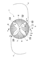
本実施形態における多焦点眼内レンズ(以下、「眼内レンズ1」という。)は、図1に示すように、光学部10と支持部12を備える。
First Embodiment
[Description of the Intraocular Lens]
The multifocal intraocular lens in the present embodiment (hereinafter referred to as “
本実施形態の光学部10は、図1〜図3に示すように、円盤形状に形成される。光学部10は、眼内に置いたときに角膜側となる前面20(前面の光学面)と、網膜側となる後面22(後面の光学面)を有する。なお、図2と図3に示す例では、前面20と後面22の両面が凸面で形成される。
The
光学部10は、例えば、PMMA(ポリメチルメタクリレート)等の硬い材料や、シリコーン等の単体、又は、アクリル酸エステルとメタクリル酸エステルの複合材料からなる折り曲げ可能な材料から形成される。光学部10を、金型などにより一体的に成形したり、切削加工により形成してもよい。なお、光学部10の詳細は、後述する。
The
支持部12は、光学部10を被検者の眼内にて固定支持するためのものである。本実施形態の支持部12は、一対形成される。支持部12はその一端(基端)が光学部10側に接合され、他端(先端)を自由端としたループ形状を有する。支持部12を、PMMA(ポリメチルメタクリレート)、ポリプロピレン、ポリイミド等の樹脂にて形成してもよい。本実施形態の支持部12は、光学部10の前面20に対し所定の角度(例えば、0〜10度程度)となるように接合される。これにより、光学部10の後面22が嚢内で押し付けられた状態で好適に光学部10が配置されるようになる。
The
なお、図1では、光学部10と支持部12とが別々に形成された後に一体化されるスリーピースタイプの眼内レンズを例に挙げる。しかし、これ以外にも本実施形態は、同一素材の光学部10と支持部12とが切削加工、モールディング加工により一体的に形成されるワンピース型の眼内レンズにも適用することができる。
In FIG. 1, a three-piece type intraocular lens in which the
〔光学部の詳細説明〕
本実施形態における光学部10は、図1〜図3に示すように、その後面22に、ベースカーブCrを備える。また、光学部10は、その前面20に、ベースカーブCf1を備える。ベースカーブとは、回折領域30の回折格子42(後述する)の存在を無視した場合の、前面20および後面22の各々の滑らかな全体形状を示す。ここで、本実施形態におけるベースカーブCr,Cf1は、入射光を屈折力により屈折させて遠用焦点f0に集光させるための曲面形状である。なお、ベースカーブCr,Cf1の一方は平面形状であってもよい。
[Detailed Description of Optical Section]
The
本実施形態の光学部10は、その後面22に、回折領域30と非回折領域32を備える。そして、光学部10の周方向について回折領域30と非回折領域32の第2領域32bとが順に形成される。本実施形態の回折領域30は、入射光を近用焦点f1(遠用焦点f0よりも近方の焦点位置)に集光させる領域である。すなわち、入射光は、回折領域30を通ることにより回折し、近用焦点f1に集光される。本実施形態の非回折領域32は、入射光を所定の遠用焦点f0(近用焦点f1よりも遠方の焦点位置)に集光させる領域である。すなわち、入射光は、非回折領域32を通ることにより遠用焦点f0に集光される。
The
本実施形態では、光学部10が持つ屈折率と曲率とによって得られる屈折度数に、回折領域30により発生する加入度が加えられることによって、眼内レンズ1に複数の焦点が与えられる。本実施形態では、眼内レンズ1を眼内に設置した被検者が遠方視を行うための所定の遠用焦点f0(遠用度数)と、被検者が近方視を行うための所定の近用焦点f1(近用度数)が与えられる。
In this embodiment, a plurality of focal points are given to the
本実施形態の回折領域30は、後面22の一部の領域に形成される。具体的には、回折領域30は、後面22にて4カ所形成される。4個の回折領域30は、光学部10の径方向について光学部10の中央部分(非回折領域32の第1領域32a、中心領域)よりも外周部10a側の位置にて、光学部10の周方向について各々等間隔に(90°おきに)間隔を空けながら形成される。すなわち、光軸O(光学部10の中心軸)を中心にして対称に形成される一対の回折領域30が、合計2対形成される。
The
本実施形態では、回折領域30における光学部10の周方向の幅δAは、光学部10の径方向の位置に応じて変化する。具体的には、幅δAは、光学部10の径方向について、光軸O側から外周部10a側に向かって、一旦大きくなった後、徐々に小さくなる。
In the present embodiment, the width δA of the
本実施形態の回折領域30には、光軸Oを中心として同心円弧状に形成される複数の円弧体40が形成される。光軸Oを含む平面で見た場合の各々の円弧体40の断面は、略鋸歯状に形成される(図3参照)。そして、光学部10の径方向について隣り合う円弧体40同士の境界部分に、回折格子42が設けられる。回折格子42は、各々の円弧体40における光軸O側の面に形成される。
In the
本実施形態の回折領域30の位相差Pは、1である。これにより、1次光(近用焦点f1に集光される光)の回折効率(所定の焦点に集光される光の配分)は、ほぼ100%となる。すなわち、回折領域30において、入射光は、回折格子42により回折されて、ほぼ100%、近用焦点f1に集光される。なお、位相差Pは、好ましくは1であるが、1の近傍でもよい。詳細には、回折領域30で得られる1次光の回折効率は、80%以上が好ましい。より好ましくは、回折領域30で得られる1次光の回折効率は、90%以上が好ましい。1次光の回折効率を100%に近づけるほど、回折領域30で生じる不要な次数の回折光を抑制できる。
The phase difference P of the
なお、公知の回折型モデルの多焦点眼内レンズでは、回折領域で複数の焦点を付与する代わりに、回折領域で発生する不要な複数次回折光が発生する。例えば、位相差Pを0.5とすると遠方視(0次光)、近方視(1次光)へのエネルギー配分はそれぞれ約40%となり、残りの約20%は不要な複数次回折光となる。この不要な回折光は、グレアやハロー等の不快な光の要因となる。 In the multifocal intraocular lens of the known diffractive model, instead of providing a plurality of focal points in the diffractive area, unnecessary multiple order diffracted light generated in the diffractive area is generated. For example, assuming that the phase difference P is 0.5, the energy distribution to far vision (0th order light) and near vision (1st order light) is approximately 40% each, and the remaining approximately 20% is unnecessary multiple order diffracted light Become. The unnecessary diffracted light causes unpleasant light such as glare and halo.
一方、本実施形態の眼内レンズ1は、回折領域30で1つの焦点(1次光)のみを付与する代わりに、1次光の回折効率を上げる。これによって、回折領域30で生じる不要な回折光を抑制する。よって、不要な回折光の発生を抑制しつつも、回折領域30と非回折領域32とによって、複数の焦点を提供する。
On the other hand, the
ここで、位相差Pは、0次光(遠用焦点f0に集光される光)と1次光のエネルギー配分に関わるパラメータである。すなわち、位相差Pは、回折領域30の回折格子42により所定の焦点(本実施形態では、近用焦点f1)に集光される光の光量をqとし、回折領域30の回折格子42により集光される全ての入射光の光量をQとするときに、以下の数式で算出される。
[式1]
P=q/Q
Here, the phase difference P is a parameter related to the energy distribution of 0th-order light (light to be focused on the far focus f0) and 1st-order light. That is, with the phase difference P, the light quantity of the light condensed to a predetermined focal point (in this embodiment, the near focus f1 in the present embodiment) by the
[Equation 1]
P = q / Q
また、回折格子42における光軸O方向の高さHは、光学部10の径方向について一定である。なお、高さHは、設計波長をλとし、周辺媒質(例えば、水)の屈折率をn1とし、光学部10の材料の屈折率をn2としたときに、以下の数式により算出される値に設定される。
[式2]
H=(P×λ)/(n2−n1)
Further, the height H in the direction of the optical axis O in the
[Formula 2]
H = (P × λ) / (n2-n1)
ここでは、一例として、位相差Pを1とし、設計波長λを546nmとし、屈折率n1を1.336とし、屈折率n2を1.52とする。すると、回折格子42の高さHは、0.00297mmとなる。
Here, as an example, the phase difference P is 1, the design wavelength λ is 546 nm, the refractive index n1 is 1.336, and the refractive index n2 is 1.52. Then, the height H of the
本実施形態の非回折領域32には、回折格子42が形成されず、ベースカーブCrが形成される。すなわち、非回折領域32におけるレンズ面の曲率は、ベースカーブCrの曲率と等しい。
The
本実施形態の非回折領域32は、第1領域32aと第2領域32bを備える。第1領域32aは、光学部10の中央部分(光軸Oを中心とする円形状の部分)に形成される。第2領域32bは、第1領域32aよりも外周部10a側の位置にて、光学部10の周方向について隣り合う回折領域30同士の間の部分に形成される。
The
なお、図1に示す例では、第1領域32aの直径d1は、光学部10の直径d2の25%の大きさであるが、特にこれに限定されず、20%〜70%の大きさであることが好ましい。
In the example shown in FIG. 1, the diameter d1 of the
本実施形態の非回折領域32の第2領域32bにおける光学部10の周方向の幅δBは、光学部10の径方向の位置に応じて変化する。具体的には、幅δBは、光学部10の径方向について光軸O側から外周部10a側に向かうほど、大きくなる。これにより、光学部10の径方向について外周部10a側に向かうほど、光学部10の周方向における回折領域30の占める割合は小さくなる一方で、光学部10の周方向における非回折領域32の占める割合は大きくなる。
The width δB of the circumferential direction of the
換言すると、光軸Oを中心とする仮想円の円周上に回折領域30が重なる割合は、仮想円の径が大きくなるほど小さくなる。一方で、仮想円の円周上に非回折領域32が重なる割合は、仮想円の径が大きくなるほど大きくなる。ただし、本実施形態では、仮想円の径が第1領域32aの径(直径d1)よりも大きい場合に上記の関係が成り立つ。
In other words, the overlapping ratio of the
さらに言い換えて説明を行う。光軸Oを中心とする仮想円の径が、患者眼の最小の瞳孔径(一般的には約3mm)よりも大きい所定の径(本実施形態では、第1領域32aの径よりも大きい径)以上となる周縁領域について考察する。本実施形態では、少なくとも周縁領域では、仮想円の内側の領域において回折領域30の面積が占める割合は、仮想円の径が大きくなるほど小さくなる。一方で、仮想円の内側の領域において非回折領域32の面積が占める割合は、仮想円の径が大きくなるほど大きくなる。この場合、少なくとも周縁領域においては、患者眼の瞳孔径が大きくなるほど、近用のエネルギー配分(つまり、瞳孔を通過する光の光量のうち、近用焦点f1に集光される光の光量の割合)が小さくなる。従って、夜間遠方視を行うために患者眼の瞳孔が大きく開いた場合に、近用焦点f1に集光される光は、グレアまたはハローとして患者に認識され難くなる。
In other words, the explanation will be made. The diameter of the virtual circle centered on the optical axis O is larger than the diameter of the
なお、一例として、図1に示すように、光学部10の周方向における非回折領域32の占める割合は、光学部10の径方向について、第1領域32aと第2領域32bの境界部分の位置(回折領域30における最も光軸O側の位置)で30%(あるいは、20%〜70)であり、最も外周部10a側の位置で100%である。
As an example, as illustrated in FIG. 1, the ratio of the
ここで、遠方視、近方視を得るために、例えば光学部100の後面102に、レンズ面の曲率が互いに異なる複数の領域が設けられる比較例(屈折型デザインと呼ばれる多焦点眼内レンズ)を想定する。すると、この比較例においては、図11に示すように、各領域(領域104と領域106)の境界部分の段差h0が大きくなってしまう。通常、屈折型構造において段差h0の境界部は滑らかな曲線で繋がれるが、境界部において不要な屈折、反射光が多く発生する可能性がある。そうすると、例えば、被検者の網膜上に結ばれる像のコントラストが低下して、被検者は近方視や遠方視を快適に行うことができないおそれがある。
Here, in order to obtain far vision and near vision, for example, a comparative example in which a plurality of regions having different curvatures of the lens surface are provided on the
これに対し、本実施形態の眼内レンズ1によれば、光学部10は、入射光を回折させる回折格子42が形成される回折領域30と、ベースカーブCrが形成される非回折領域32と、を備える。
On the other hand, according to the
すると、回折格子42の高さHは非常に小さいため、図4に示すように、回折領域30と非回折領域32における境界部分の段差hは、前記の比較例における段差h0と比べて、非常に小さい。そのため、段差hにおいて、0次や1次回折光以外の不要な屈折、反射光が発生し難くなる。したがって、例えば、被検者の網膜上に結ばれる像のコントラストが低下し難くなる。ゆえに、被検者は近方視や遠方視を快適に行うことができる。
Then, since the height H of the
また、非回折領域32の幅δBは、光学部10の径方向について変化する。これにより、光学部10の径方向について、遠用と近用のエネルギーの配分(0次光(遠用焦点f0に集光させる光の光量)と1次光(近用焦点f1に集光させる光の光量)の配分)を自在に調整できる。
Further, the width δB of the
また、本実施形態では、回折領域30は入射光を近用焦点f1に集光させる領域であり、非回折領域32は入射光を遠用焦点f0に集光させる領域である。そして、光学部10の径方向について外周部10a側に向かうほど、光学部10の周方向における非回折領域32の第2領域32bの占める割合が大きくなる。これにより、少なくとも周縁領域では、光学部10の径方向について外周部10a側に向かうほど、遠用のエネルギーが多くなる(0次光の配分が高くなる)。夜間遠方視を行う際には被検者の瞳孔は大きく開いた状態になるため、グレアおよびハローの原因となる近用のエネルギーの割合は相対的に小さくなる。従って、被検者は快適に遠方視を行うことができる。例えば、被検者は、瞳孔が大きく開きがちな夜間の車の運転を、グレアやハロー等が抑制された状態で、快適に行うことができる。また、周縁領域よりも内側では、回折領域30と非回折領域32が適切な割合で併存している。従って、例えば、近方視を行うために被検者の瞳孔が縮瞳する(近見反射と呼ばれる現象)と、患者は、回折領域30によって集光される光によって適切に近方視を行うことができる。
Further, in the present embodiment, the
また、本実施形態の眼内レンズ1は、回折領域30の位相差Pが1であるので、前述した公知の回折型デザインの多焦点眼内レンズに対して、回折領域30において不要な回折光(例えば2次光など)の発生が抑制される。そのため、例えばグレアやハロー等の発生が抑制される。したがって、被検者の網膜上にて結ばれる像のコントラスト低下が抑制される。
Further, since the phase difference P of the
また、光学部10の中央部分(図1における第1領域32aの箇所であり、換言すると中心領域)に、非回折領域32の第1領域32aが形成される。このようにして、光学部10の中央部分に回折格子42が形成される領域を少なくすることで、光学部10の成形が容易となる。そのため、眼内レンズ1の生産性が向上する。
In addition, the
また、光軸Oを中心にして対称に形成される一対の回折領域30が2対形成される。即ち、本実施形態の回折領域30は、光学部10の周方向について互いに間隔を空けながら複数形成され、非回折領域32は、光学部10の周方向について隣り合う回折領域30同士の間に形成される。これにより、例えば、被検者の眼内において眼内レンズ1の位置ずれが生じても、被検者は快適に近方視や遠方視を行うことができる。また、例えば、視軸に対して瞳孔の中心が偏心している被検者、または瞳孔の形状が非円形(例えば楕円形)な被検者に本実施形態の眼内レンズ1を設置しても、被検者は、快適に近方視や遠方視を行うことができる。また、本実施形態の眼内レンズ1は更に、回折領域30は、周方向で等間隔に形成される。これによって、例えば、前述した位置ずれの影響をより受け難くなる。
Further, two pairs of
なお、第1実施形態の眼内レンズ1の一部を形成させた第1変形例として、光学部10の径方向外側に向かうほど、回折領域30を通過した入射光のうち近用焦点f1に集光される光の割合が小さくなるように、回折領域30の回折格子42を形成してもよい。一例として、図5に示すように、回折格子42の高さHは、光学部10の径方向について外周部10a側へ向かうほど小さくてもよい(つまり、眼内レンズ1がアポダイゼーション特性を有してもよい)。この場合、夜間遠方視を行うために瞳孔が大きく開くと、近用のエネルギーの相対的な割合がさらに小さくなる。よって、グレアやハローがさらに低減される。なお、この場合でも、光学部10の中心に近い部分では、回折領域30の位相差Pは1に近い方が望ましい。
As a first modified example in which a portion of the
また、回折領域30が形成される数は、特に限定されない。例えば、第2変形例として、回折領域30は、後面22にて8カ所形成されてもよい。
Moreover, the number in which the diffraction area |
また、回折領域30と非回折領域32は、前面20に形成されても良く、または、前面20と後面22の両面に形成されても良い。また、第1実施形態では、光学部10の中央部分に第1領域32aが形成される。しかし、第1領域32aが形成される部分が回折領域30に置き換えられていてもよい。この場合、光学部10の径方向について光軸O側に向かうほど、近用のエネルギーの割合が大きくなる(1次光の配分が高くなる)。そのため、近方視を行うために被検者の瞳孔が縮瞳した状態になると、遠用のエネルギーの割合が相対的に低くなる。よって、被検者は快適に近方視を行うことができる。
In addition, the
次に、第2実施形態と第3実施形態について説明するが、第1実施形態や他の実施形態と同等の構成要素については、同一の符号を付して説明を省略し、異なった点を中心に述べる。 Next, the second embodiment and the third embodiment will be described. The components equivalent to those of the first embodiment and the other embodiments are denoted by the same reference numerals and descriptions thereof will be omitted, and different points will be described. I will focus on it.
<第2実施形態>
本実施形態における光学部10は、図6〜図8に示すように、その後面22に、ベースカーブCrを備える。また、光学部10は、その前面20に、ベースカーブCf2を備える。ここで、本実施形態におけるベースカーブCr,Cf2は、入射光を屈折力により屈折させて近用焦点f1に集光させるための曲面形状である。
Second Embodiment
The
ここで、第2実施形態におけるベースカーブCf2の曲率は、第1実施形態におけるベースカーブCf1の曲率よりも大きく設定される。また、第1実施形態のベースカーブCrと第2実施形態のベースカーブCrは同じである。そのため、第2実施形態のベースカーブCr,Cf2は、第1実施形態のベースカーブCr,Cf1よりも入射光を近距離で集光させる。これにより、入射光は、ベースカーブCf2とベースカーブCrを通ると、近用焦点f1に集光される。 Here, the curvature of the base curve Cf2 in the second embodiment is set larger than the curvature of the base curve Cf1 in the first embodiment. Further, the base curve Cr of the first embodiment and the base curve Cr of the second embodiment are the same. Therefore, the base curves Cr and Cf2 of the second embodiment condense incident light at a closer distance than the base curves Cr and Cf1 of the first embodiment. Thereby, incident light is condensed to the near focus f1 when passing through the base curve Cf2 and the base curve Cr.
本実施形態の光学部10は、その後面22に、回折領域50と非回折領域52を備える。そして、光学部10の周方向について回折領域50と非回折領域52の第2領域52bとが順に形成される。本実施形態の回折領域50は、入射光を遠用焦点f0に集光させる領域である。すなわち、入射光は、回折領域50を通ることにより回折し、遠用焦点f0に集光される。本実施形態の非回折領域52は、入射光を近用焦点f1に集光させる領域である。すなわち、入射光は、非回折領域52を通ることにより近用焦点f1に集光される。
The
本実施形態の回折領域50は、後面22の一部の領域に形成される。具体的には、回折領域50は、後面22にて4カ所形成される。4個の回折領域50は、光学部10の径方向について光学部10の中央部分(非回折領域52の第1領域52a)よりも外周部10a側の位置にて、光学部10の周方向について各々等間隔に(90°おきに)間隔を空けながら形成される。すなわち、光軸Oを中心にして対称に形成される一対の回折領域50が、合計2対形成される。
The
本実施形態の回折領域50における光学部10の周方向の幅δAは、光学部10の径方向の位置に応じて変化する。具体的には、幅δAは、光学部10の径方向について光軸O側から外周部10a側に向かうほど、大きくなる。これにより、光学部10の径方向について外周部10a側に向かうほど、光学部10の周方向における非回折領域52の第2領域52bの占める割合は小さくなる一方で、光学部10の周方向における回折領域50の占める割合は大きくなる。
The width δA in the circumferential direction of the
本実施形態の回折領域50には、光軸Oを中心として同心円弧状に形成される複数の円弧体60が形成される。光軸Oを含む平面で見た場合の各々の円弧体60の断面は、略鋸歯状に形成される(図8参照)。そして、光学部10の径方向について隣り合う円弧体60同士の境界部分に、回折格子62が設けられる。回折格子62は、各々の円弧体60における光学部10の外周部10a側の面に形成される。
In the
本実施形態の回折領域50の位相差Pは、1である。これにより、回折格子62における0次光の回折効率は、回折領域表面の反射損失を無視して、ほぼ100%となる。すなわち、回折領域50において、入射光は、回折格子62により回折されて、ほぼ100%、遠用焦点f0に集光される。
The phase difference P of the
本実施形態の非回折領域52には、回折格子62が形成されず、ベースカーブCrが形成される。すなわち、非回折領域52におけるレンズ面の曲率は、ベースカーブCrの曲率と等しい。
The
本実施形態の非回折領域52は、第1領域52aと第2領域52bを備える。第1領域52aは、光学部10の中央部分に形成される。第2領域52bは、第1領域52aよりも外周部10a側の位置にて、光学部10の周方向について隣り合う回折領域50同士の間の部分に形成される。
The
本実施形態の非回折領域52の第2領域52bにおける光学部10の周方向の幅δBは、光学部10の径方向の位置に応じて変化する。具体的には、幅δBは、光学部10の径方向について、光軸O側から外周部10a側に向って、一旦大きくなった後、徐々に小さくなる。
The width δB of the circumferential direction of the
本実施形態によれば、回折領域50は入射光を遠用焦点f0に集光させる領域であり、非回折領域52は入射光を近用焦点f1に集光させる領域である。そして、光学部10の径方向について外周部10a側に向かうほど、光学部10の周方向における回折領域50の占める割合が大きくなる。これにより、光学部10の中央部分(非回折領域52の第1領域52a)よりも外周部10a側の位置にて、光学部10の径方向について外周部10a側に向かうほど、遠用のエネルギーが多くなる。そのため、夜間遠方視を行うために被検者の瞳孔が大きく開いた状態となると、不要な近用のエネルギーが相対的に低くなるので、被検者は快適に遠方視を行うことができる。例えば、被検者は、瞳孔が大きく開きがちな夜間の車の運転を、グレアやハローが抑制された状態で、快適に行うことができる。また、光学部10の径方向について光軸O側に向かうほど、近用のエネルギーが多くなる。そのため、近方視を行う際には被検者の瞳孔は小さく開いた状態になるが、被検者は快適に近方視を行うことができる。
According to the present embodiment, the
なお、第2実施形態の眼内レンズ1の一部を形成させた第1変形例として、光学部10の径方向外側に向かうほど、回折領域50を通過した入射光のうち遠用焦点f0に集光される光の割合が小さくなるように、回折領域50の回折格子62を形成してもよい。一例として、回折格子62の高さHは、光学部10の径方向について外周部10a側へ向かうほど小さくてもよい。つまり、眼内レンズ1がアポダイゼーション特性を有してもよい。
As a first modified example in which a part of the
また、回折領域50が形成される数は、特に限定されない。例えば、第2変形例として、回折領域50は、後面22にて8カ所形成されてもよい。
Moreover, the number in which the diffraction area |
<第3実施形態>
本実施形態において、図9と図10に示すように、回折領域30は、光学部10の周方向についてO軸を中心とする中心角α1の範囲内であって、かつ、光学部10の径方向について光軸Oの位置から外周部10aの近傍の位置まで形成され、扇形状に形成される。回折領域30は、入射光を回折させて近用焦点f1に集光させる。非回折領域32は、入射光を遠用焦点f0に集光させる。また、中心角α1は、図9に示す例では120°であるが、特にこれに限定されず、90°〜270°であることが好ましい。本実施形態では、第1実施形態および第2実施形態に比べて、回折領域30および非回折領域32の形状が単純になる。従って、眼内レンズ1の製造が容易になる。
Third Embodiment
In the present embodiment, as shown in FIGS. 9 and 10, the
なお、第3実施形態の眼内レンズ1の一部を形成させた第1変形例として、回折格子42の高さHは、光学部10の径方向について外周部10a側へ向かうほど小さくてもよい。つまり、眼内レンズ1がアポダイゼーション特性を有してもよい。
As a first modification in which a portion of the
また、第2変形例として、回折領域30に代えて非回折領域52とし、且つ非回折領域32に代えて回折領域50としてもよい。
As a second modification, the
なお、上記した実施の形態は単なる例示にすぎず、本開示を何ら限定するものではなく、その要旨を逸脱しない範囲内で種々の改良、変形が可能であることはもちろんである。 The embodiment described above is merely an example, and does not limit the present disclosure in any way, and it goes without saying that various improvements and modifications can be made without departing from the scope of the invention.
例えば、第1実施形態の回折領域30や第2実施形態の回折領域50は、光学部10の径方向について、光軸Oの位置まで形成されてもよい。
For example, the
また、前面20と後面22は、凸面や凹面や平面の組み合わせで構成されてもよい。
Further, the
また、第3実施形態の回折領域30は、複数形成されてもよい。また、複数の回折領域30の各々が異なる焦点を提供してもよい。かかる態様の場合、例えば、複数の回折領域30の各々の位相差Pを1としつつ、焦点位置が互いに異なる複数種類の回折領域を用意して、3以上の焦点を付与する眼内レンズ1を提供できる。
Further, a plurality of
また、図1の実施形態(第1実施形態)では、回折領域30と非回折領域32とによって2種類の焦点を付与する。しかしながら、2種類の焦点を付与する各々の領域が共に回折領域であってもよい。つまり、非回折領域は必ずしも必要ない。この場合、各々の回折領域のベースカーブが同じであればよい。なお、各々の回折領域の位相差が1であることが望ましいことは言うまでもない。ただし、この場合には、第1〜3実施形態に比べて、光学部10に形成される回折領域の割合が大きくなる。回折領域では、意図しない光の屈折および散乱が、非回折領域に比べて生じやすくなる。従って、第1〜3実施形態では、非回折領域を用いない場合に比べて、意図しない光の屈折および散乱が生じ難い。
Further, in the embodiment of FIG. 1 (first embodiment), two types of focal points are given by the
1 眼内レンズ
10 光学部
10a 外周部
12 支持部
20 前面
22 後面
30 回折領域
32 非回折領域
32a 第1領域
32b 第2領域
40 円弧体
42 回折格子
50 回折領域
52 非回折領域
52a 第1領域
52b 第2領域
60 円弧体
62 回折格子
Cr (後面の)ベースカーブ
Cf1 (前面の)ベースカーブ
Cf2 (前面の)ベースカーブ
f0 遠用焦点
f1 近用焦点
O 光軸
δA 幅
δB 幅
P 位相差
q 光量
Q 光量
H 高さ
λ 設計波長
n1 屈折率
n2 屈折率
d1 (第1領域の)直径
d2 (光学部の)直径
h 段差
α1 中心角
DESCRIPTION OF
Claims (3)
前面の光学面および後面の光学面を有し、入射光を集光させる光学部を備え、
前記光学部は、
前記光学面の一部の領域に形成され、前記入射光を回折させて少なくとも第1焦点位置に集光させる回折格子が設けられる回折領域と、
前記回折領域が設けられた前記光学面のうち、前記回折領域以外の領域に曲面または平面によって形成され、前記第1焦点位置よりも遠方または近方の第2焦点位置に前記入射光を集光させる非回折領域と、
を備え、
前記光学部の周方向について前記回折領域と前記非回折領域とが順に形成され、
前記回折領域および前記非回折領域のうち近方に前記入射光を集光させる領域の面積が、前記光学部の光軸を中心とする円の内側の領域において占める割合は、前記円の径が大きくなるほど小さくなり、
前記回折領域の位相差が1であること、
を特徴とする多焦点眼内レンズ。 A multifocal intraocular lens inserted into the eye of a patient's eye, comprising:
An optical unit having an optical surface on the front surface and an optical surface on the rear surface, and condensing incident light;
The optical unit is
A diffraction area provided in a partial area of the optical surface and provided with a diffraction grating that diffracts the incident light and condenses the incident light to at least a first focal position;
Of the optical surface provided with the diffractive region, a curved surface or a flat surface is formed in a region other than the diffractive region, and the incident light is collected at a second focal position farther or closer than the first focal position. The non-diffracting region
Equipped with
The diffraction region and the non-diffraction region are sequentially formed in the circumferential direction of the optical unit,
The ratio of the area of the area of the diffraction area and the non-diffraction area to which the incident light is condensed to the near side in the area inside the circle centered on the optical axis of the optical unit is the diameter of the circle The bigger it gets smaller,
That the phase difference of the diffraction region is 1;
Multifocal intraocular lens characterized by
前記回折領域および前記非回折領域のうち近方に前記入射光を集光させる領域における前記光学部の周方向の幅は、前記光学部の径方向について、前記光学部の光軸側から前記光学部の外周部に向かって、一旦大きくなった後、徐々に小さくなること、The width in the circumferential direction of the optical unit in the region for condensing the incident light to the near side among the diffractive region and the non-diffraction region is the optical axis from the optical axis side of the optical unit in the radial direction of the optical unit And then gradually become smaller toward the outer periphery of the part,
を特徴とする多焦点眼内レンズ。Multifocal intraocular lens characterized by
前記非回折領域が、少なくとも前記光学部の光軸を中心とする中心領域に形成されることを特徴とする多焦点眼内レンズ。The multifocal intraocular lens, wherein the non-diffraction region is formed at least in a central region centered on the optical axis of the optical unit.
Priority Applications (1)
| Application Number | Priority Date | Filing Date | Title |
|---|---|---|---|
| JP2015030871A JP6500484B2 (en) | 2015-02-19 | 2015-02-19 | Multifocal intraocular lens |
Applications Claiming Priority (1)
| Application Number | Priority Date | Filing Date | Title |
|---|---|---|---|
| JP2015030871A JP6500484B2 (en) | 2015-02-19 | 2015-02-19 | Multifocal intraocular lens |
Publications (3)
| Publication Number | Publication Date |
|---|---|
| JP2016150213A JP2016150213A (en) | 2016-08-22 |
| JP2016150213A5 JP2016150213A5 (en) | 2018-03-22 |
| JP6500484B2 true JP6500484B2 (en) | 2019-04-17 |
Family
ID=56694934
Family Applications (1)
| Application Number | Title | Priority Date | Filing Date |
|---|---|---|---|
| JP2015030871A Expired - Fee Related JP6500484B2 (en) | 2015-02-19 | 2015-02-19 | Multifocal intraocular lens |
Country Status (1)
| Country | Link |
|---|---|
| JP (1) | JP6500484B2 (en) |
Families Citing this family (5)
| Publication number | Priority date | Publication date | Assignee | Title |
|---|---|---|---|---|
| JP6504332B1 (en) | 2018-08-09 | 2019-04-24 | 株式会社ニコン | Ophthalmic lens and method of manufacturing ophthalmic lens |
| WO2020194713A1 (en) * | 2019-03-28 | 2020-10-01 | 株式会社ニコン | Ophthalmic lens and ophthalmic lens production method |
| WO2020194712A1 (en) * | 2019-03-28 | 2020-10-01 | 株式会社ニコン | Ophthalmic lens and method for producing ophthalmic lens |
| AU2020416508A1 (en) | 2019-12-30 | 2022-08-25 | Amo Groningen B.V. | Achromatic lenses with zone order mixing for vision treatment |
| AU2020418360A1 (en) | 2019-12-30 | 2022-08-25 | Amo Groningen B.V. | Achromatic lenses for vision treatment |
Family Cites Families (9)
| Publication number | Priority date | Publication date | Assignee | Title |
|---|---|---|---|---|
| DE3381691D1 (en) * | 1982-10-13 | 1990-08-02 | Ng Trustees & Nominees Ltd | BIFOCAL CONTACT LENSES. |
| US5089023A (en) * | 1990-03-22 | 1992-02-18 | Massachusetts Institute Of Technology | Diffractive/refractive lens implant |
| FR2661914B1 (en) * | 1990-05-11 | 1994-05-06 | Essilor Internal Cie Gle Optique | METHOD FOR MANUFACTURING A TRANSPARENT POLYMER LENS WITH MODULATED REFRACTION INDEX. |
| US5096285A (en) * | 1990-05-14 | 1992-03-17 | Iolab Corporation | Multifocal multizone diffractive ophthalmic lenses |
| US5198844A (en) * | 1991-07-10 | 1993-03-30 | Johnson & Johnson Vision Products, Inc. | Segmented multifocal contact lens |
| US7441894B2 (en) * | 2006-02-09 | 2008-10-28 | Alcon Manufacturing, Ltd. | Pseudo-accommodative IOL having diffractive zones with varying areas |
| US20090088840A1 (en) * | 2007-10-02 | 2009-04-02 | Simpson Michael J | Zonal diffractive multifocal intraocular lenses |
| US8709079B2 (en) * | 2009-06-09 | 2014-04-29 | Novartis Ag | IOL with varying correction of chromatic aberration |
| JP6190133B2 (en) * | 2013-03-25 | 2017-08-30 | Hoya株式会社 | Ophthalmic lens design method and ophthalmic lens manufacturing method |
-
2015
- 2015-02-19 JP JP2015030871A patent/JP6500484B2/en not_active Expired - Fee Related
Also Published As
| Publication number | Publication date |
|---|---|
| JP2016150213A (en) | 2016-08-22 |
Similar Documents
| Publication | Publication Date | Title |
|---|---|---|
| JP5824000B2 (en) | Pseudo-tuning IOL with diffraction zones with various areas | |
| KR101478501B1 (en) | Apodized diffractive iol with frustrated diffractive region | |
| KR101314775B1 (en) | Pseudo-accomodative iol having multiple diffractive patterns | |
| KR101248488B1 (en) | Apodized aspheric diffractive lenses | |
| JP6500484B2 (en) | Multifocal intraocular lens | |
| JP5462154B2 (en) | Diffractive intraocular lens | |
| JP5453419B2 (en) | Depth of focus (EDOF) lens with increased degree of pseudo-adjustment by pupil dynamics | |
| JP6491106B2 (en) | Method and system for providing an intraocular lens with improved depth of field | |
| JP6258869B2 (en) | Composite refraction diffraction IOL apodized for pseudo-adjustment | |
| JP5480980B2 (en) | Intraocular lens | |
| JP4551489B2 (en) | Manufacturing method of diffractive lens | |
| JP5824076B2 (en) | Diffractive multifocal ophthalmic lens and manufacturing method thereof | |
| JP5481588B1 (en) | Accommodating intraocular lens | |
| KR20090009303A (en) | Aspheric multifocal diffractive ophthalmic lens | |
| WO2018150236A1 (en) | Diffractive multifocal implantable lens device | |
| JP2011528272A (en) | Adjustable IOL with annular optics and extended depth of focus | |
| JP2008049167A (en) | Truncated diffractive intraocular lenses | |
| US10537421B2 (en) | Diffractive-refractive lens | |
| JP5460211B2 (en) | Multifocal intraocular lens | |
| TWI555522B (en) | An extended depth of focus (edof) lens to increase pseudo-accommodation by utilizing pupil dynamics | |
| JPWO2021181300A5 (en) |
Legal Events
| Date | Code | Title | Description |
|---|---|---|---|
| A521 | Request for written amendment filed |
Free format text: JAPANESE INTERMEDIATE CODE: A523 Effective date: 20180208 |
|
| A621 | Written request for application examination |
Free format text: JAPANESE INTERMEDIATE CODE: A621 Effective date: 20180208 |
|
| A977 | Report on retrieval |
Free format text: JAPANESE INTERMEDIATE CODE: A971007 Effective date: 20181017 |
|
| A131 | Notification of reasons for refusal |
Free format text: JAPANESE INTERMEDIATE CODE: A131 Effective date: 20181030 |
|
| A601 | Written request for extension of time |
Free format text: JAPANESE INTERMEDIATE CODE: A601 Effective date: 20181226 |
|
| A521 | Request for written amendment filed |
Free format text: JAPANESE INTERMEDIATE CODE: A523 Effective date: 20190201 |
|
| TRDD | Decision of grant or rejection written | ||
| A01 | Written decision to grant a patent or to grant a registration (utility model) |
Free format text: JAPANESE INTERMEDIATE CODE: A01 Effective date: 20190219 |
|
| A61 | First payment of annual fees (during grant procedure) |
Free format text: JAPANESE INTERMEDIATE CODE: A61 Effective date: 20190304 |
|
| R150 | Certificate of patent or registration of utility model |
Ref document number: 6500484 Country of ref document: JP Free format text: JAPANESE INTERMEDIATE CODE: R150 |
|
| LAPS | Cancellation because of no payment of annual fees |