JP6500042B2 - Medical electrode - Google Patents
Medical electrode Download PDFInfo
- Publication number
- JP6500042B2 JP6500042B2 JP2016573595A JP2016573595A JP6500042B2 JP 6500042 B2 JP6500042 B2 JP 6500042B2 JP 2016573595 A JP2016573595 A JP 2016573595A JP 2016573595 A JP2016573595 A JP 2016573595A JP 6500042 B2 JP6500042 B2 JP 6500042B2
- Authority
- JP
- Japan
- Prior art keywords
- conductive
- support sheet
- medical electrode
- pad
- snap element
- Prior art date
- Legal status (The legal status is an assumption and is not a legal conclusion. Google has not performed a legal analysis and makes no representation as to the accuracy of the status listed.)
- Active
Links
- 239000000853 adhesive Substances 0.000 claims description 32
- 230000001070 adhesive effect Effects 0.000 claims description 32
- 230000033001 locomotion Effects 0.000 claims description 24
- WABPQHHGFIMREM-UHFFFAOYSA-N lead(0) Chemical compound [Pb] WABPQHHGFIMREM-UHFFFAOYSA-N 0.000 claims description 19
- 238000007789 sealing Methods 0.000 claims description 15
- 238000000034 method Methods 0.000 claims description 4
- 239000006260 foam Substances 0.000 claims description 3
- 238000004891 communication Methods 0.000 claims description 2
- 239000011888 foil Substances 0.000 claims description 2
- 239000000463 material Substances 0.000 claims description 2
- 239000002861 polymer material Substances 0.000 claims 1
- 239000002390 adhesive tape Substances 0.000 description 5
- 238000012544 monitoring process Methods 0.000 description 5
- 241001465754 Metazoa Species 0.000 description 3
- 230000008859 change Effects 0.000 description 3
- 238000003745 diagnosis Methods 0.000 description 3
- 208000024172 Cardiovascular disease Diseases 0.000 description 2
- 208000029078 coronary artery disease Diseases 0.000 description 2
- 238000002405 diagnostic procedure Methods 0.000 description 2
- 230000002354 daily effect Effects 0.000 description 1
- 201000010099 disease Diseases 0.000 description 1
- 208000037265 diseases, disorders, signs and symptoms Diseases 0.000 description 1
- 239000003814 drug Substances 0.000 description 1
- 230000002526 effect on cardiovascular system Effects 0.000 description 1
- 230000000694 effects Effects 0.000 description 1
- 230000003203 everyday effect Effects 0.000 description 1
- 230000006870 function Effects 0.000 description 1
- 208000019622 heart disease Diseases 0.000 description 1
- 230000004217 heart function Effects 0.000 description 1
- 230000007774 longterm Effects 0.000 description 1
- 230000004199 lung function Effects 0.000 description 1
- 238000004519 manufacturing process Methods 0.000 description 1
- 238000012986 modification Methods 0.000 description 1
- 230000004048 modification Effects 0.000 description 1
- 230000035790 physiological processes and functions Effects 0.000 description 1
- 238000009662 stress testing Methods 0.000 description 1
- 238000012360 testing method Methods 0.000 description 1
- 230000009466 transformation Effects 0.000 description 1
Images


Classifications
-
- A—HUMAN NECESSITIES
- A61—MEDICAL OR VETERINARY SCIENCE; HYGIENE
- A61B—DIAGNOSIS; SURGERY; IDENTIFICATION
- A61B5/00—Measuring for diagnostic purposes; Identification of persons
- A61B5/24—Detecting, measuring or recording bioelectric or biomagnetic signals of the body or parts thereof
- A61B5/25—Bioelectric electrodes therefor
- A61B5/251—Means for maintaining electrode contact with the body
- A61B5/257—Means for maintaining electrode contact with the body using adhesive means, e.g. adhesive pads or tapes
- A61B5/259—Means for maintaining electrode contact with the body using adhesive means, e.g. adhesive pads or tapes using conductive adhesive means, e.g. gels
-
- A—HUMAN NECESSITIES
- A61—MEDICAL OR VETERINARY SCIENCE; HYGIENE
- A61B—DIAGNOSIS; SURGERY; IDENTIFICATION
- A61B5/00—Measuring for diagnostic purposes; Identification of persons
- A61B5/05—Detecting, measuring or recording for diagnosis by means of electric currents or magnetic fields; Measuring using microwaves or radio waves
-
- A—HUMAN NECESSITIES
- A61—MEDICAL OR VETERINARY SCIENCE; HYGIENE
- A61B—DIAGNOSIS; SURGERY; IDENTIFICATION
- A61B5/00—Measuring for diagnostic purposes; Identification of persons
- A61B5/24—Detecting, measuring or recording bioelectric or biomagnetic signals of the body or parts thereof
- A61B5/25—Bioelectric electrodes therefor
- A61B5/271—Arrangements of electrodes with cords, cables or leads, e.g. single leads or patient cord assemblies
- A61B5/273—Connection of cords, cables or leads to electrodes
- A61B5/274—Connection of cords, cables or leads to electrodes using snap or button fasteners
-
- A—HUMAN NECESSITIES
- A61—MEDICAL OR VETERINARY SCIENCE; HYGIENE
- A61B—DIAGNOSIS; SURGERY; IDENTIFICATION
- A61B5/00—Measuring for diagnostic purposes; Identification of persons
- A61B5/24—Detecting, measuring or recording bioelectric or biomagnetic signals of the body or parts thereof
- A61B5/25—Bioelectric electrodes therefor
- A61B5/279—Bioelectric electrodes therefor specially adapted for particular uses
- A61B5/28—Bioelectric electrodes therefor specially adapted for particular uses for electrocardiography [ECG]
- A61B5/283—Invasive
- A61B5/288—Invasive for foetal cardiography, e.g. scalp electrodes
-
- A—HUMAN NECESSITIES
- A61—MEDICAL OR VETERINARY SCIENCE; HYGIENE
- A61B—DIAGNOSIS; SURGERY; IDENTIFICATION
- A61B5/00—Measuring for diagnostic purposes; Identification of persons
- A61B5/24—Detecting, measuring or recording bioelectric or biomagnetic signals of the body or parts thereof
- A61B5/25—Bioelectric electrodes therefor
- A61B5/279—Bioelectric electrodes therefor specially adapted for particular uses
- A61B5/291—Bioelectric electrodes therefor specially adapted for particular uses for electroencephalography [EEG]
-
- A—HUMAN NECESSITIES
- A61—MEDICAL OR VETERINARY SCIENCE; HYGIENE
- A61B—DIAGNOSIS; SURGERY; IDENTIFICATION
- A61B5/00—Measuring for diagnostic purposes; Identification of persons
- A61B5/24—Detecting, measuring or recording bioelectric or biomagnetic signals of the body or parts thereof
- A61B5/316—Modalities, i.e. specific diagnostic methods
- A61B5/389—Electromyography [EMG]
-
- A—HUMAN NECESSITIES
- A61—MEDICAL OR VETERINARY SCIENCE; HYGIENE
- A61B—DIAGNOSIS; SURGERY; IDENTIFICATION
- A61B2560/00—Constructional details of operational features of apparatus; Accessories for medical measuring apparatus
- A61B2560/04—Constructional details of apparatus
-
- A—HUMAN NECESSITIES
- A61—MEDICAL OR VETERINARY SCIENCE; HYGIENE
- A61B—DIAGNOSIS; SURGERY; IDENTIFICATION
- A61B2562/00—Details of sensors; Constructional details of sensor housings or probes; Accessories for sensors
- A61B2562/02—Details of sensors specially adapted for in-vivo measurements
- A61B2562/0209—Special features of electrodes classified in A61B5/24, A61B5/25, A61B5/283, A61B5/291, A61B5/296, A61B5/053
- A61B2562/0217—Electrolyte containing
-
- A—HUMAN NECESSITIES
- A61—MEDICAL OR VETERINARY SCIENCE; HYGIENE
- A61B—DIAGNOSIS; SURGERY; IDENTIFICATION
- A61B2562/00—Details of sensors; Constructional details of sensor housings or probes; Accessories for sensors
- A61B2562/16—Details of sensor housings or probes; Details of structural supports for sensors
- A61B2562/164—Details of sensor housings or probes; Details of structural supports for sensors the sensor is mounted in or on a conformable substrate or carrier
Description
本発明は、電極に関し、特に生体から生理的信号を得るため、生体との電気的接触を確立する医療電極に関する。 The present invention relates to an electrode, and more particularly to a medical electrode that establishes electrical contact with a living body in order to obtain a physiological signal from the living body.
現代医療において、生体に付けられる医療電極を用いて、生体からの生理的信号を得る多くの医療装置が開発されている。例えば、ECG(心電計)デバイスは、心臓及び肺機能に関連付けられる電気的活動を示す情報を含む医療(即ち生体電位)信号を得るために広く使われる。電極は、ECGデバイス及び例えば人又は動物といった生体の皮膚の間の電気的接続を確立し、心血管疾患の診断に関して、又は、心血管及び他の生理的機能の監視に関して重要な基礎の1つである生理的信号を得るために使用される。 In modern medicine, many medical devices have been developed that obtain physiological signals from a living body using medical electrodes attached to the living body. For example, ECG (electrocardiograph) devices are widely used to obtain medical (ie, biopotential) signals that contain information indicative of electrical activity associated with heart and lung function. The electrode establishes an electrical connection between the ECG device and the skin of a living organism, such as a human or animal, and is one of the important foundations for the diagnosis of cardiovascular disease or for the monitoring of cardiovascular and other physiological functions. Is used to obtain a physiological signal.
ストレス試験ECGは、疑わしい又は既知の心血管疾患、最も一般には冠状動脈疾患(CAD)を持つ人に関して実行される診断試験である。ストレス試験手順は、ターゲットとなる人がしばしばトレッドミル又は二輪車上でエクササイズすることを必要とする。ホルターECGは、通常24時間以上かかる長期にわたるECG監視又は記録を通してのみ心臓疾患が検出されることができる人に実行される診断試験である。ホルター記録又は監視の間、不可避的に、人の頻繁な体運動が、日常生体の一部として存在する。取得されるECG信号の品質を確実にするため、ストレスECG及びホルターECGは、品質電極が人の皮膚と信頼性が高い電気的接触を確立することを必要とする。 The stress test ECG is a diagnostic test performed on a person with a suspicious or known cardiovascular disease, most commonly coronary artery disease (CAD). Stress testing procedures often require the target person to exercise on a treadmill or motorcycle. Holter ECG is a diagnostic test performed on a person whose heart disease can only be detected through long-term ECG monitoring or recording, which usually takes 24 hours or more. During Holter recording or monitoring, inevitably, frequent human body movements exist as part of everyday life. In order to ensure the quality of the acquired ECG signal, stress ECG and Holter ECG require that the quality electrode establish a reliable electrical contact with the human skin.
図1は、ECGデバイスに用いられる従来の電極の分解斜視図であり、図2は、それが、例えば人又は動物といった生体の皮膚に付けられるときの図1の電極の断面図である。 FIG. 1 is an exploded perspective view of a conventional electrode used in an ECG device, and FIG. 2 is a cross-sectional view of the electrode of FIG. 1 when it is applied to the skin of a living body such as a human or animal.
図1及び図2に示されるように、既存の医療電極131は、両面粘着テープ147を持つ環状粘着性パッド133、中央穴137、及び導電性パッド135を一般に有する。導電性パッドは、例えば導電性ゲルで満たされ、環状粘着性パッド133の中央穴137に配置されるフォームパッドである。電極131は、第1の導電性スナップ要素139、第2の導電性スナップ141及び第1及び第2のスナップ要素の間に配置される密封フィルム143を更に有する。第1の導電性スナップ要素139は、導電性パッド135の第1の側135aに付けられ、第2の導電性スナップ141にはめ込まれる。密封フィルム143の外側部は、環状粘着性パッド133の1つの側133aに付けられる。
As shown in FIGS. 1 and 2, the existing
電極は、リリースライナ145を有することができる。これは環状粘着性パッド133の第2の側133bに付けられて、人に対して電極を適用する前に除去されることができる。使用の際、医療電極131の第2の導電性スナップ要素141は、リードワイヤLのコネクタ要素Cにはめ込まれる。これは取得された信号をECGデバイスに転送する。
The electrode can have a
明らかに、トレッドミル又は二輪車における運動又は日常生体の一部としての体運動は、リードワイヤLが移動することをもたらす。リードワイヤLが医療電極に固定されるとき、リードワイヤLを介して移動によりもたらされる機械的な力は、第1及び第2の導電性スナップ要素から転送され、導電性パッド135が、生体の皮膚Sに対して移動することをもたらす。これは、順に、導電性パッド135及び皮膚Sの間の電気的接触インピーダンスを変化させる。これは、ECG信号がゆがむことをもたらし、相対的な疾患のECG信号監視及び診断に負のインパクトをもたらす。
Obviously, movement on a treadmill or two-wheeled vehicle or body movement as part of a daily life causes the lead wire L to move. When the lead wire L is secured to the medical electrode, the mechanical force resulting from the movement through the lead wire L is transferred from the first and second conductive snap elements and the
この問題を解決するため、既知の方法は、ソフトウェアアルゴリズムを使用して、雑音が多いECG波形が取得された後、歪曲又は干渉をフィルタリングする又は修正する。しかし、ソフトウェアフィルタリングは、斯かる歪曲をもたらす運動の正確な情報の不足が原因で、多くのECG詳細を予想外に削除する場合がある。こうして、ECGデバイス、特にストレスECG及びホルターECG監視又は診断に関して、改良された医療電極を提供する必要性が存在する。 To solve this problem, known methods use software algorithms to filter or correct distortion or interference after a noisy ECG waveform is acquired. However, software filtering may delete many ECG details unexpectedly due to a lack of accurate information on the motion that causes such distortion. Thus, there is a need to provide improved medical electrodes for ECG devices, particularly for stress ECG and Holter ECG monitoring or diagnosis.
本発明の1つの側面によれば、医療電極が、中央穴を持ち、生体に付けられるよう構成される環状粘着性パッドと、上記環状パッドの上記中央穴に配置され、上記生体と直接接触するよう構成される導電性パッドと、第1の導電性スナップ要素と、上記導電性パッド及び上記第1の導電性スナップ要素の間の電気的通信を確立するよう構成される導電性要素と、上記導電性パッドを封止するよう構成される密封フィルムであって、上記環状粘着性パッド及び上記密封フィルムの間の上記導電性要素の少なくとも一部を固定するよう構成される密封フィルムとを有し、上記導電性要素の柔軟性及び/又は長さが、上記導電性パッドが移動することをもたらすことなく、上記第1の導電性スナップ要素が移動することを可能にするよう十分に大きく選ばれる。こうして、リードワイヤが動くとき、リードワイヤから第1の導電性スナップ要素に転送される機械的な力は、導電性パッド及び生体の間の相対的な運動を生じさせない。結果として、導電性パッド及び生体の間の電気的接触インピーダンスは、体運動と共に変化するものではない。これにより、取得された生理的信号が歪められることが防止される。 According to one aspect of the present invention, a medical electrode has a central hole and is configured to be attached to a living body, and an annular adhesive pad is disposed in the central hole of the annular pad, and is in direct contact with the living body. A conductive pad configured as described above; a first conductive snap element; a conductive element configured to establish electrical communication between the conductive pad and the first conductive snap element; A sealing film configured to seal the conductive pad, the sealing film configured to secure at least a portion of the conductive element between the annular adhesive pad and the sealing film. The flexibility and / or length of the conductive element is large enough to allow the first conductive snap element to move without causing the conductive pad to move. It is selected. Thus, when the lead wire moves, the mechanical force transferred from the lead wire to the first conductive snap element does not cause relative movement between the conductive pad and the living body. As a result, the electrical contact impedance between the conductive pad and the living body does not change with body movement. This prevents the acquired physiological signal from being distorted.
より有利なことに、医療電極は、上記第1の導電性スナップ要素がはめ込まれる第2の導電性スナップ要素と、上記第1の導電性スナップ要素及び上記第2の導電性スナップ要素の間に配置される支持シートとを更に有する。上記支持シートが、中心部、外側部並びに上記中心部及び上記外側部の間の内側部を含む。上記支持シートの上記中心部は、上記第1の導電性スナップ要素と上記第2の導電性スナップ要素の間に挟まれる。上記支持シートの上記外側部は、上記環状粘着性パッドの第1の側に付けられるか又は付着される。上記支持シートの上記内側部は、上記環状粘着性パッドから自由であり、上記支持シートの上記内側部の少なくとも一部が,上記支持シートの上記外側部に対して移動することを可能にする態様で設計される。 More advantageously, the medical electrode is between a second conductive snap element into which the first conductive snap element is fitted, and between the first conductive snap element and the second conductive snap element. And a support sheet to be disposed. The support sheet includes a center portion, an outer portion, and an inner portion between the center portion and the outer portion. The central portion of the support sheet is sandwiched between the first conductive snap element and the second conductive snap element. The outer portion of the support sheet is attached to or attached to the first side of the annular adhesive pad. A mode in which the inner portion of the support sheet is free from the annular adhesive pad and allows at least a part of the inner portion of the support sheet to move relative to the outer portion of the support sheet. Designed with.
また、より有利なことに、支持シートは、支持シートの内側部において形成される1つ又は複数のスリットを持つ。これは、第2の伝導スナップ要素を介してリードワイヤから転送される機械的な力で緊張状態にあるとき、支持シートの内側部が変形することを可能にする。これは、支持シートの外側部及び従って環状粘着性パッドが移動することをもたらすことなく、より多くの自由度で、支持シートの内側部が支持シートの外側部に対して移動することを可能にし、体運動がリードワイヤの移動をもたらすとき、導電性パッド及び人の皮膚の間の電気的接触の信頼性を効果的に増加させる。 More advantageously, the support sheet has one or more slits formed in the inner part of the support sheet. This allows the inner part of the support sheet to deform when in tension with a mechanical force transferred from the lead wire via the second conductive snap element. This allows the inner part of the support sheet to move relative to the outer part of the support sheet with more freedom without causing the outer part of the support sheet and thus the annular adhesive pad to move. Effectively increases the reliability of electrical contact between the conductive pad and the human skin when body movement results in movement of the lead wire.
本発明のこれら及び他の目的、特徴及び特性が、この構造の関連要素及び部品の組合せにおける動作方法及び機能、並びに製造コストと共に、対応する図面を参照して以下の明細書及び添付の特許請求の範囲を考慮することにより、一層明らかになるだろう。図面、明細書及び特許請求の範囲はすべて、この明細書の一部を形成する。同様な参照符号は、さまざまな図面における対応する部分を表す。しかしながら、図面が図示及び説明のためにだけあること、及び本発明の範囲を規定するものとして意図されないことは、明示的に理解されたい。 These and other objects, features and characteristics of the present invention, as well as the method of operation and function in combination of related elements and parts of this structure, and the manufacturing costs, refer to the following description and appended claims with reference to the corresponding drawings. It will become more apparent by considering the scope of. The drawings, specification and claims all form part of this specification. Like reference symbols designate corresponding parts in the various drawings. It should be expressly understood, however, that the drawings are for illustration and description only and are not intended to define the scope of the invention.
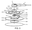
図3及び図4に示されるように、本発明による医療電極201は、環状粘着性パッド203、導電性パッド205、第1の導電性スナップ要素209、導電性要素211及び密封フィルム213を有する。
As shown in FIGS. 3 and 4, the medical electrode 201 according to the present invention includes an annular
環状粘着性パッド203は、中央穴207を持ち、例えば人又は動物といった生体に付けられる。導電性パッド205は、環状粘着性パッド203の中央穴207に配置され、人の皮膚Sと直接接触する。有利には、導電性パッド205は、導電性ゲルで満たされるフォームパッドである。
The annular
第1の導電性スナップ要素209は、密封フィルム213に隣接して配置される。導電性要素211は、導電性パッド205及び第1の導電性スナップ要素209の間の電気的接続を確立するよう構成され、それは、1つの端で第1の導電性スナップ要素209に接続され、他端で導電性パッド205に接続される導電性フォイル又はストリップとすることができる。
The first
密封フィルム213は、導電性パッド205、特に導電性ゲルが環状粘着性パッド203の中央穴207から逃げるのを防止するため、環状粘着性パッド203の第1の側203aに付けられるよう構成される。一方、密封フィルム213は、環状粘着性パッド203及び密封フィルム213の間の少なくとも一部の導電性要素211も固定する。
The
医療電極201は、例えば、両面粘着テープ217を用いて、環状粘着性パッド203の第2の側203bに付けられるよう構成されるリリースライナ215を更に有することができる。環状粘着性パッド203の第2の側203bは、環状粘着性パッド203の第1の側203aに対して対向し、医療電極201が適用されるとき、人に付けられる又は付着される。使用の状態において、リリースライナ215は除去され、両面粘着テープ217を持つ環状粘着性パッド203が、人の皮膚Sに付着される。
The medical electrode 201 can further include a
医療電極201がECGデバイスで使用されるとき、医療電極の第1の導電性スナップ要素209は、リードワイヤLのコネクタ要素Cにはめ込まれる。これは取得された信号をECGデバイス(図示省略)に転送する。人の体運動は、リードワイヤL及び従って第1の導電性スナップ要素が移動することをもたらす。第1の導電性スナップ要素に掛けられる機械的な力から導電性パッドを保護するため、導電性要素211の柔軟性又は長さは、機械的な力を吸収するか又はこれに適応し、及び従って、導電性パッド205が移動することをもたらすことなく、第1の導電性スナップ要素209が移動することを可能にするよう十分大きく設計される。結果として、導電性パッド205及び人の皮膚Sの間の電気的接触インピーダンスは、リードワイヤLの移動に伴い変化することはなく、従って、安定的で正確なECG信号取得を確実にする。
When the medical electrode 201 is used in an ECG device, the first
有利には、本発明による医療電極201は、第2の導電性スナップ要素219及び支持シート221を更に有する。支持シート221は、第1の導電性スナップ要素209及び第2の導電性スナップ要素219の間に配置される。詳細には、支持シート221は、中央部分221a、外側部221b及び中央部分221aと外側部221bとの間の内側部221cを有する。支持シート221の中央部分221aは、第2の導電性スナップ要素209が、第1の導電性スナップ要素219にはめ込まれるとき、第1の導電性スナップ要素209及び第2の導電性スナップ要素219の間にはさまれる。支持シート221の外側部221bは、例えば両面粘着テープ223を用いて、環状粘着性パッド203の第1の側203aに付けられるか又は付着される。一方、支持シート221の内側部221cは、第1のパッド203の第1の側203aからは自由である。支持シート221の内側部221cは、支持シート221の内側部221cの少なくとも一部が、環状粘着性パッド203が移動することをもたらすことなく、支持シート221の外側部221bに対して移動する自由を持つことを可能にする態様で設計される。
Advantageously, the medical electrode 201 according to the invention further comprises a second
密封フィルム及び導電性要素の一部が環状粘着性パッドと支持シートの間に挟まれるので、第1のスナップ要素によりもたらされる導電性要素の部分の運動によって、密封フィルムが環状粘着性パッドから分離したようになるのを防止することができる。 Because the sealing film and a portion of the conductive element are sandwiched between the annular adhesive pad and the support sheet, movement of the portion of the conductive element provided by the first snap element separates the sealing film from the annular adhesive pad. Can be prevented.
ある実施形態において、支持シート221は、弾性体から作られる。支持シート221の内側部221c及び外側部221bは、異なる柔軟性を持つ異なる弾性体で作られることができる。好ましくは、支持シート221の内側部221cは、支持シート221の外側部221bより柔軟であり、これは、支持シート221の外側部が移動することをもたらすことなく、内側部221cが移動する自由を持つことを可能にする。
In some embodiments, the
代替的に、支持シート221は、弾性体から作られる支持シート221より剛性を持つポリマー物質から作られることができる。斯かる場合、支持シート221の内側部221cが支持シート221の外側部221bに対して移動する自由を持つことを確実にするため、複数のスリットが、支持シート221の内側部221cにおいて形成される。
Alternatively, the
図5、図6及び図7は、例示的な支持シート221を示す。図5及び図6に示されるように、円弧状スリット225a、225bの第1のペアが、支持シート221の内側部221cにおいて、直径に沿って互いに反対側に形成される。有利には、円弧状スリット225a、225bの第1のペアの半径より大きい半径を持つ円弧状スリット225c、225dの第2のペアが、支持シート221の内側部221cにおいて、直径に沿って互いに反対側に形成されることができる。好ましくは、円弧状スリット225c、225dの第2のペアは、特定の角度分、例えば85°〜90°、スリット225a、225bの第1のペアからオフセットされる。
5, 6 and 7 show an
スリットの数は、2つのペアに限定されるものではなく、2つ以上のスリットのペアも可能である点に留意されたい。更に、スリットは、任意の適切な形状、例えば直線又は湾曲形状とすることができる。例えば、1つの螺旋スリットだけが、支持シート221の内側部221cにおいて形成されることができる。もちろん、1つ以上の螺旋スリットも可能である。支持シート221の内側部221cが、1つ又は複数スリットを持つので、支持シート221の内側部221cは、支持シート221の外側部221bより柔軟である。こうして、第1及び第2の導電性スナップ要素がリードワイヤLの運動が原因で緊張状態にあるとき、支持シート221の内側部221cは、変形することができ、及び従って支持シート221の外側部221bに対して移動することができる。図7は、支持シート221の内側部221cの斯かる可能な変形又は運動を示す。
Note that the number of slits is not limited to two pairs, and more than two pairs of slits are possible. Further, the slit can be any suitable shape, such as a straight or curved shape. For example, only one spiral slit can be formed in the
使用の際、図5に示されるように、医療電極の第2の導電性スナップ要素219は、ECGデバイス(図示省略)へとリードするリードワイヤLのコネクタ要素Cにはめ込まれ、リリースライナ215が除去され、医療電極201がその後適用され、両面粘着テープ217により人の皮膚Sに付けられる。トレッドミル又は二輪車における人のエクササイズによって、又は、体運動によって、リードワイヤが移動するとき、機械的な力が生成され、この力は、第1の導電性スナップ要素209及び第2の導電性スナップ要素219が動くことをもたらす。支持シート221の内側部221cの柔軟性又は変形性は、支持シート221の内側部221cが、第1の導電性スナップ要素209及び第2の導電性スナップ要素219と共に移動することを可能にする。結果として、トレッドミル又は二輪車における人のエクササイズが原因によるリードワイヤの運動により、又は、体運動により生成される機械的な力は、支持シート221の外側部、及び従って環状粘着性パッド203に対して転送されない。導電性要素211の柔軟性及び/又は長さは、導電性要素211の一部が支持シート221の内側部221cに従うことを可能にするように十分に大きく選ばれるので、こうして、導電性要素211及び第1の導電性スナップ要素209を介した導電性パッド205から第2の導電性スナップ要素219への信頼性が高い電気的接続が保証される。即ち、リードワイヤが人の皮膚Sに対して垂直に、又は、これに沿って移動するかどうかに関係なく、リードワイヤの運動によりもたらされる機械的な力は、導電性パッド205に転送されない。こうして、第2のパッド205及び生体の皮膚Sの間の相対的な運動は存在しない。結果として、環状粘着性パッド205及び人の皮膚Sの間の電気的接触インピーダンスは、リードワイヤの運動とともに変化するものではない。ECG信号取得の安定性及び精度は、改良される。
In use, as shown in FIG. 5, the second
本発明の好ましい実施形態は、ECGデバイスに関する電極として解釈されるが、本発明による電極は、他の医療デバイス、例えばEEG(脳波)デバイスと共に使用されることもできる点を理解されたい。 Although preferred embodiments of the present invention are to be construed as electrodes for ECG devices, it should be understood that the electrodes according to the present invention can also be used with other medical devices, such as EEG (electroencephalogram) devices.
最も実際的かつ好ましい実施形態であると現在考慮されるものに基づき、本発明が説明目的で詳述されたが、斯かるその詳細は、単に説明目的のためだけにあること、及び本発明は、開示された実施形態に限定されず、添付の特許請求の範囲の精神及び範囲内にある修正及び均等な構成を覆うよう意図されることを理解されたい。 Although the present invention has been described in detail for purposes of illustration based on what is presently considered to be the most practical and preferred embodiment, such details are merely for illustrative purposes and It is to be understood that the invention is not limited to the disclosed embodiments, but is intended to cover modifications and equivalent arrangements that fall within the spirit and scope of the appended claims.
Claims (13)
中央穴を持ち、生体に付けられるよう構成される環状粘着性パッドと、
前記環状粘着性パッドの前記中央穴において配置される導電性パッドと、
第1の導電性スナップ要素と、
前記導電性パッド及び前記第1の導電性スナップ要素の間の電気的通信を確立するよう構成される導電性要素と、
前記環状粘着性パッドの第1の側に付けられる密封フィルムであって、前記環状粘着性パッド及び前記密封フィルムの間の前記導電性要素の少なくとも一部を固定するよう構成される密封フィルムとを有し、
前記導電性要素が、一端が前記導電性パッドに電気的に接続され、他端が前記第1の導電性スナップ要素に電気的に接続され、かつ前記導電性パッドが移動することをもたらすことなく、前記第1の導電性スナップ要素が移動することを可能にするのに十分な柔軟性及び/又は長さを持つ柔軟な導電性箔及び/又はストリップである、医療電極。 A medical electrode,
An annular adhesive pad having a central hole and configured to be attached to a living body;
A conductive pad disposed in the central hole of the annular adhesive pad;
A first conductive snap element;
A conductive element configured to establish electrical communication between the conductive pad and the first conductive snap element;
A sealing film attached to a first side of the annular adhesive pad, the sealing film configured to secure at least a portion of the conductive element between the annular adhesive pad and the sealing film; Have
The conductive element has one end electrically connected to the conductive pad and the other end electrically connected to the first conductive snap element and without causing the conductive pad to move. A medical electrode, which is a flexible conductive foil and / or strip with sufficient flexibility and / or length to allow the first conductive snap element to move.
前記第1の導電性スナップ要素及び前記第2の導電性スナップ要素の間に配置される支持シートとを更に有し、
前記支持シートが、中心部、外側部並びに前記中心部及び前記外側部の間の内側部を含み、前記支持シートの前記中心部は、前記第1の導電性スナップ要素と前記第2の導電性スナップ要素の間に挟まれ、前記支持シートの前記外側部が、前記環状粘着性パッドに付着され、前記支持シートの前記内側部は、前記環状粘着性パッドから自由であり、前記導電性パッドが移動することをもたらすことなく、前記支持シートの前記内側部の少なくとも一部が、前記支持シートの前記外側部に対して移動することを可能にする態様で設計される、請求項1に記載の医療電極。 A second conductive snap element into which the first conductive snap element is fitted;
A support sheet disposed between the first conductive snap element and the second conductive snap element;
The support sheet includes a central portion, an outer portion, and an inner portion between the central portion and the outer portion, and the central portion of the support sheet includes the first conductive snap element and the second conductive portion. Sandwiched between snap elements, the outer portion of the support sheet is attached to the annular adhesive pad, the inner portion of the support sheet is free from the annular adhesive pad, and the conductive pad is The method of claim 1, wherein at least a portion of the inner portion of the support sheet is designed in a manner that allows movement relative to the outer portion of the support sheet without causing movement. Medical electrode.
Applications Claiming Priority (5)
| Application Number | Priority Date | Filing Date | Title |
|---|---|---|---|
| CN2014081579 | 2014-07-03 | ||
| CNPCT/CN2014/081579 | 2014-07-03 | ||
| EP14183400 | 2014-09-03 | ||
| EP14183400.2 | 2014-09-03 | ||
| PCT/EP2015/065165 WO2016001393A1 (en) | 2014-07-03 | 2015-07-02 | Medical electrode |
Publications (3)
| Publication Number | Publication Date |
|---|---|
| JP2017524413A JP2017524413A (en) | 2017-08-31 |
| JP2017524413A5 JP2017524413A5 (en) | 2018-06-21 |
| JP6500042B2 true JP6500042B2 (en) | 2019-04-10 |
Family
ID=53489984
Family Applications (1)
| Application Number | Title | Priority Date | Filing Date |
|---|---|---|---|
| JP2016573595A Active JP6500042B2 (en) | 2014-07-03 | 2015-07-02 | Medical electrode |
Country Status (6)
| Country | Link |
|---|---|
| US (1) | US10349853B2 (en) |
| EP (1) | EP3164064A1 (en) |
| JP (1) | JP6500042B2 (en) |
| CN (1) | CN106470602B (en) |
| RU (1) | RU2696531C2 (en) |
| WO (1) | WO2016001393A1 (en) |
Families Citing this family (12)
| Publication number | Priority date | Publication date | Assignee | Title |
|---|---|---|---|---|
| US20140276270A1 (en) | 2013-03-13 | 2014-09-18 | Passy-Muir, Inc. | Systems and methods for stimulating swallowing |
| WO2018037389A1 (en) * | 2016-08-25 | 2018-03-01 | Inesc Tec - Instituto De Engenharia De Sistemas E Computadores, Tecnologia E Ciência | Medical device with rotational flexible electrodes |
| JP6972523B2 (en) * | 2016-09-13 | 2021-11-24 | セイコーエプソン株式会社 | Electronics |
| AT519280B1 (en) * | 2016-10-21 | 2019-08-15 | Leonh Lang | Electrode for attachment to human skin |
| WO2018116161A1 (en) | 2016-12-19 | 2018-06-28 | Intento Sa | Electrode and connector assemblies for non-invasive transcutaneous electrical stimulation and biological signal sensing |
| EP3446624A1 (en) * | 2017-08-23 | 2019-02-27 | Koninklijke Philips N.V. | Skin electrode |
| CN108392197A (en) * | 2017-12-29 | 2018-08-14 | 深圳市亮动科技开发有限公司 | A kind of conduction pad pasting and electrocardiograph monitoring device |
| AT522511B1 (en) * | 2019-04-16 | 2023-08-15 | Leonh Lang Holding Gmbh | Electrode for attachment to human skin and method of making an electrode |
| US20200330323A1 (en) | 2019-04-19 | 2020-10-22 | Alex Jolly | Vibratory Nerve Exciter |
| SE544480C2 (en) * | 2020-03-16 | 2022-06-14 | Piotrode Medical Ab | Body electrode for electrophysilogical signals monitoring and recording |
| CN111920406B (en) * | 2020-07-21 | 2022-01-14 | 联想(北京)有限公司 | Electrocardio electrode piece assembly and preparation method thereof |
| SE544506C2 (en) * | 2021-02-10 | 2022-06-28 | Piotrode Medical Ab | Body electrode for electrophysiological signals monitoring and recording |
Family Cites Families (28)
| Publication number | Priority date | Publication date | Assignee | Title |
|---|---|---|---|---|
| US1938231A (en) | 1931-11-03 | 1933-12-05 | Bozidar J Ukropina | Pipe making machine |
| SU392643A1 (en) * | 1971-05-13 | 1974-01-15 | вители И. Ф. Головко Всесоюзный научно исследовательский институт хирургической анпаратуры , инструментов , Московский государственный университет М. В. Ломоносова | ELECTRODE FOR REGISTRATION OF BIOELECTRIC |
| US3740703A (en) | 1971-11-24 | 1973-06-19 | R Sessions | Terminal clamp |
| US3750094A (en) | 1972-03-09 | 1973-07-31 | Zenco Engineering Corp | Electrical connector |
| US3977392A (en) * | 1975-04-21 | 1976-08-31 | Eastprint, Inc. | Medical electrode |
| US4114263A (en) | 1977-03-14 | 1978-09-19 | Roman Szpur | Method of manufacturing medical electrodes |
| US4196737A (en) | 1978-04-21 | 1980-04-08 | C. R. Bard, Inc. | Transcutaneous electrode construction |
| US4370984A (en) * | 1979-04-30 | 1983-02-01 | Ndm Corporation | X-Ray transparent medical electrode |
| US4522211A (en) * | 1979-12-06 | 1985-06-11 | C. R. Bard, Inc. | Medical electrode construction |
| US4370934A (en) * | 1980-02-04 | 1983-02-01 | Haeussler Wilhelm | Method for production of a compression-proof shelter and prefabricated means for use in this method |
| US4934383A (en) * | 1982-04-23 | 1990-06-19 | George Glumac | Electrode |
| US4617935A (en) | 1985-03-12 | 1986-10-21 | Ndm Corporation | Medical electrode |
| US4938231A (en) * | 1985-10-22 | 1990-07-03 | Telectronics N.V. | Defibrillator electrode |
| US5042498A (en) | 1990-04-06 | 1991-08-27 | Hewlett-Packard Company | Intelligent electrocardiogram system |
| JPH06178765A (en) * | 1992-11-16 | 1994-06-28 | Physiometrix Inc | Unifying contact member dried under low impedance and low durometer and method and apparatus for using such contact member as this |
| JPH11113866A (en) * | 1997-10-13 | 1999-04-27 | Nabco Ltd | Myoelectric sensor |
| DK1301123T3 (en) | 2000-07-19 | 2005-01-24 | Medicotest As | Skin electrode with a bypass element |
| JP2003102695A (en) * | 2001-09-28 | 2003-04-08 | Fukuda Denshi Co Ltd | Biological signal collecting device and its controlling method |
| US6745082B2 (en) | 2001-10-22 | 2004-06-01 | Jens Axelgaard | Current-controlling electrode with adjustable contact area |
| US6796967B2 (en) | 2001-10-22 | 2004-09-28 | Nps Pharmaceuticals, Inc. | Injection needle assembly |
| AT502879B1 (en) * | 2004-11-22 | 2009-02-15 | Lang Leonh | MEDICAL ELECTRODE |
| JP2006178765A (en) * | 2004-12-22 | 2006-07-06 | Toyota Motor Corp | Design support apparatus |
| RU2294135C1 (en) | 2005-06-16 | 2007-02-27 | ОБЩЕСТВО С ОГРАНИЧЕННОЙ ОТВЕТСТВЕННОСТЬЮ НАУЧНО-ПРОИЗВОДСТВЕННО-КОНСТРУКТОРСКАЯ ФИРМА "Медиком МТД" | Electrode device for measuring biopotentials |
| ATE518478T1 (en) * | 2008-02-04 | 2011-08-15 | Koninkl Philips Electronics Nv | SHIELDED ELECTRODE CONNECTOR |
| US8251736B2 (en) * | 2008-09-23 | 2012-08-28 | Tyco Electronics Corporation | Connector assembly for connecting an electrical lead to an electrode |
| EP2419006B1 (en) * | 2009-04-15 | 2015-09-30 | 3M Innovative Properties Company | Deep tissue temperature probe constructions |
| BR112012017760A2 (en) * | 2009-12-23 | 2016-04-19 | Delta Dansk Elektronik Lys Og Akustik | monitoring device for attaching to a surface of a subject |
| EP2844130B1 (en) * | 2012-05-03 | 2023-04-19 | Sensible Medical Innovations Ltd. | Patches for the attachment of electromagnetic (em) probes |
-
2015
- 2015-07-02 CN CN201580036339.XA patent/CN106470602B/en active Active
- 2015-07-02 JP JP2016573595A patent/JP6500042B2/en active Active
- 2015-07-02 WO PCT/EP2015/065165 patent/WO2016001393A1/en active Application Filing
- 2015-07-02 RU RU2017103458A patent/RU2696531C2/en active
- 2015-07-02 EP EP15732010.2A patent/EP3164064A1/en not_active Withdrawn
- 2015-07-02 US US15/319,099 patent/US10349853B2/en active Active
Also Published As
| Publication number | Publication date |
|---|---|
| RU2696531C2 (en) | 2019-08-02 |
| US10349853B2 (en) | 2019-07-16 |
| JP2017524413A (en) | 2017-08-31 |
| US20170127969A1 (en) | 2017-05-11 |
| WO2016001393A1 (en) | 2016-01-07 |
| CN106470602B (en) | 2019-12-31 |
| RU2017103458A (en) | 2018-08-06 |
| RU2017103458A3 (en) | 2019-02-06 |
| CN106470602A (en) | 2017-03-01 |
| EP3164064A1 (en) | 2017-05-10 |
Similar Documents
| Publication | Publication Date | Title |
|---|---|---|
| JP6500042B2 (en) | Medical electrode | |
| JP6901543B2 (en) | Electronic device for physiological monitoring | |
| FI126093B (en) | Arrangement and method for conducting electrode measurements | |
| JP6077639B2 (en) | Transducer assembly | |
| US20080312524A1 (en) | Medical Sensor Having Electrodes and a Motion Sensor | |
| JP2015533580A5 (en) | ||
| JP2020525089A (en) | Measurement of electrical activity | |
| EP3094235B1 (en) | Biosensing electrodes | |
| TWI383779B (en) | Biomedical electric wave sensor | |
| CN105943029B (en) | ECG electrode piece, leading wire connector terminal and ECG measuring device | |
| KR101780926B1 (en) | Patch type electrocardiogram sensor | |
| US20150238100A1 (en) | Sensor electrode device | |
| US20160213280A1 (en) | Medical device for contact sensing | |
| KR101668022B1 (en) | Electrode for measuring bio-signal and a method thereof | |
| KR20170019033A (en) | Sensor for measuring biological signal | |
| KR101237308B1 (en) | Multi-channel electrode assembly for measuring vital signal | |
| US11033235B2 (en) | Method and apparatus for motion artifact reduction in ECG harness | |
| AU2018279147B2 (en) | Pulse meter for newborn | |
| JP7339083B2 (en) | Electroencephalogram measurement device | |
| US20230309888A1 (en) | Apparatus and method for hybrid biosensors | |
| JPH0715001U (en) | Biomedical electrode | |
| KR102581789B1 (en) | Electrode connector attached to the skin for measuring bioelectrical signals | |
| Elango et al. | Dry electrode geometry optimization for wearable ECG devices | |
| WO2016116918A1 (en) | A one lead single-touch ecg device and means thereof | |
| US20200107742A1 (en) | Electroencephalogram measuring apparatus |
Legal Events
| Date | Code | Title | Description |
|---|---|---|---|
| A521 | Request for written amendment filed |
Free format text: JAPANESE INTERMEDIATE CODE: A523 Effective date: 20180507 |
|
| A621 | Written request for application examination |
Free format text: JAPANESE INTERMEDIATE CODE: A621 Effective date: 20180507 |
|
| A977 | Report on retrieval |
Free format text: JAPANESE INTERMEDIATE CODE: A971007 Effective date: 20190123 |
|
| TRDD | Decision of grant or rejection written | ||
| A01 | Written decision to grant a patent or to grant a registration (utility model) |
Free format text: JAPANESE INTERMEDIATE CODE: A01 Effective date: 20190228 |
|
| A61 | First payment of annual fees (during grant procedure) |
Free format text: JAPANESE INTERMEDIATE CODE: A61 Effective date: 20190318 |
|
| R150 | Certificate of patent or registration of utility model |
Ref document number: 6500042 Country of ref document: JP Free format text: JAPANESE INTERMEDIATE CODE: R150 |
|
| R250 | Receipt of annual fees |
Free format text: JAPANESE INTERMEDIATE CODE: R250 |
|
| R250 | Receipt of annual fees |
Free format text: JAPANESE INTERMEDIATE CODE: R250 |
|
| R250 | Receipt of annual fees |
Free format text: JAPANESE INTERMEDIATE CODE: R250 |