JP6497878B2 - Electronic device and control method - Google Patents

Electronic device and control method Download PDF

Info

Publication number
JP6497878B2
JP6497878B2 JP2014180497A JP2014180497A JP6497878B2 JP 6497878 B2 JP6497878 B2 JP 6497878B2 JP 2014180497 A JP2014180497 A JP 2014180497A JP 2014180497 A JP2014180497 A JP 2014180497A JP 6497878 B2 JP6497878 B2 JP 6497878B2
Authority
JP
Japan
Prior art keywords
noise
amplitude spectrum
spectrum data
unit
data obtained
Prior art date
Legal status (The legal status is an assumption and is not a legal conclusion. Google has not performed a legal analysis and makes no representation as to the accuracy of the status listed.)
Active
Application number
JP2014180497A
Other languages
Japanese (ja)
Other versions
JP2016053697A (en
JP2016053697A5 (en
Inventor
悠貴 辻本
悠貴 辻本
啓太 園田
啓太 園田
Current Assignee (The listed assignees may be inaccurate. Google has not performed a legal analysis and makes no representation or warranty as to the accuracy of the list.)
Canon Inc
Original Assignee
Canon Inc
Priority date (The priority date is an assumption and is not a legal conclusion. Google has not performed a legal analysis and makes no representation as to the accuracy of the date listed.)
Filing date
Publication date
Application filed by Canon Inc filed Critical Canon Inc
Priority to JP2014180497A priority Critical patent/JP6497878B2/en
Priority to US14/837,914 priority patent/US9462174B2/en
Publication of JP2016053697A publication Critical patent/JP2016053697A/en
Publication of JP2016053697A5 publication Critical patent/JP2016053697A5/ja
Application granted granted Critical
Publication of JP6497878B2 publication Critical patent/JP6497878B2/en
Active legal-status Critical Current
Anticipated expiration legal-status Critical

Links

Images

Description

本発明は、ノイズの低減を行うための技術に関するものである。   The present invention relates to a technique for reducing noise.

昨今のデジタルカメラに代表される撮像装置は、静止画のみならず、音声付き動画像記録機能を有する。すなわち、被写体を時間軸に連続して撮像して得た動画像と、その周囲の音声のデータも併せてメモリカード等の記憶媒体に記録できるようになっている。このような被写体の周囲の音声のように、記録の目的となる音声を、以下、「環境音」と称する。   Imaging apparatuses represented by recent digital cameras have not only still images but also moving image recording functions with sound. That is, a moving image obtained by continuously capturing an image of a subject along a time axis and surrounding audio data can be recorded together in a storage medium such as a memory card. Hereinafter, the sound to be recorded, such as the sound around the subject, is referred to as “environmental sound”.

また、撮像装置は、光学レンズを移動させることで、撮像中に被写体をフォーカスしたりズームすることができる。しかし、光学レンズの移動のための駆動時には、駆動音が発生する。近年のデジタルカメラは、筐体の小型化が進み、駆動音の発生源とマイクロホンとの距離が短くなってしまう。そのため、デジタルカメラにおけるマイクロホンは、駆動音を取得してしまい、結果的に環境音に駆動音がノイズとして重畳されてしまう可能性が高くなっていた。   In addition, the imaging apparatus can focus or zoom the subject during imaging by moving the optical lens. However, driving sound is generated during driving for moving the optical lens. In recent digital cameras, the housing has been downsized, and the distance between the drive sound source and the microphone has been shortened. Therefore, the microphone in the digital camera acquires driving sound, and as a result, there is a high possibility that the driving sound is superimposed as noise on the environmental sound.

従来から、上記のようなノイズを低減させるため、「スペクトルサブトラクション法」と称される手法が知られている(例えば、特許文献1)。このスペクトルサブトラクション法を図21を参照して簡単に説明する。同図は、デジタルカメラのブロック構成の一部である。この装置は、装置全体の制御を行う制御部2109、ユーザからの指示を受け付ける操作部2110、光学レンズやレンズ制御部等で構成される。さらに、この装置は、撮像して画像データを得る撮像部2101、マイク2205、音声を音声データとして取得する音声入力部2102、画像データ及び音声データを記憶するメモリ2103で構成される。なお、通常、メモリ2103に格納された画像データや音声データは、符号化処理され、符号化データとして記憶媒体に格納される。   Conventionally, a technique called “spectral subtraction method” is known in order to reduce the noise as described above (for example, Patent Document 1). This spectral subtraction method will be briefly described with reference to FIG. This figure is a part of a block configuration of a digital camera. This apparatus includes a control unit 2109 that controls the entire apparatus, an operation unit 2110 that receives instructions from a user, an optical lens, a lens control unit, and the like. Further, this apparatus includes an imaging unit 2101 that captures images to obtain image data, a microphone 2205, an audio input unit 2102 that acquires audio as audio data, and a memory 2103 that stores image data and audio data. Note that, normally, image data and audio data stored in the memory 2103 are encoded and stored in the storage medium as encoded data.

音声付き動画像を記録している期間、制御部2109が操作部2110を介してユーザによるズームインやズームアウト等の指示を検出すると、制御部2109は、光学レンズの位置の変更を行うよう撮像部101を制御する。撮像部2101は、これに従い、光学レンズの位置を変更するために、モータ等の駆動源を駆動する。このとき、マイク2205は、光学レンズの駆動音を拾ってしまい、結果的にマイク2205から得られる音響データは、環境音と駆動音(ノイズ)とが合成されたデータになる。図示の音声入力部2102は、この駆動音を低減する機能を持つものである。   When the control unit 2109 detects an instruction such as zoom-in or zoom-out by the user via the operation unit 2110 during the recording of the moving image with sound, the control unit 2109 changes the position of the optical lens to change the position of the optical lens. 101 is controlled. In accordance with this, the imaging unit 2101 drives a drive source such as a motor in order to change the position of the optical lens. At this time, the microphone 2205 picks up the driving sound of the optical lens, and as a result, the acoustic data obtained from the microphone 2205 is data in which the environmental sound and the driving sound (noise) are synthesized. The illustrated voice input unit 2102 has a function of reducing the drive sound.

マイク2205で検出された音はADC(アナログデジタルコンバータ)2206にて、例えば、48kHzのサンプリングレートで16ビットのデジタルデータ(以下、音響データという)に変換される。FFT2207は、時系列に並ぶ音響データ(例えば1024個の音響データ)を、FFT(高速フーリエ変換)処理して周波数毎のデータ(振幅スペクトル)に変換する。騒音低減部2200は、各周波数のデータから、ノイズの各周波数データを減算することで、ノイズ低減処理を行う。このため、騒音低減部2200は、ノイズの各周波数毎の振幅データ(ノイズプロファイル)をあらかじめ記憶しているプロファイル格納部2210と、振幅スペクトル減算部2211を有する。振幅スペクトル減算部2211は、振幅スペクトルからプロファイル格納部2210に記録されているノイズの各周波数の振幅データを減算する。その後、ノイズが減算された振幅スペクトルは、IFFT2214にて逆FFT処理され、元の時系列の音響データに戻される。この後、音声処理部2216は、その音響データに対して各種処理を行う。そして、ALC(オートレベルコントローラ)2217が音響データのレベル調節を行い、その結果は、メモリ2103に格納される。   The sound detected by the microphone 2205 is converted into 16-bit digital data (hereinafter referred to as acoustic data) by an ADC (Analog / Digital Converter) 2206 at a sampling rate of 48 kHz, for example. The FFT 2207 converts the acoustic data arranged in time series (for example, 1024 pieces of acoustic data) into FFT data (amplitude spectrum) by performing FFT (fast Fourier transform) processing. The noise reduction unit 2200 performs noise reduction processing by subtracting each frequency data of noise from each frequency data. For this reason, the noise reduction unit 2200 includes a profile storage unit 2210 that stores amplitude data (noise profile) for each frequency of noise in advance, and an amplitude spectrum subtraction unit 2211. The amplitude spectrum subtraction unit 2211 subtracts the amplitude data of each frequency of noise recorded in the profile storage unit 2210 from the amplitude spectrum. Thereafter, the amplitude spectrum from which the noise has been subtracted is subjected to inverse FFT processing by IFFT 2214 and returned to the original time-series acoustic data. Thereafter, the voice processing unit 2216 performs various processes on the acoustic data. An ALC (auto level controller) 2217 adjusts the level of the acoustic data, and the result is stored in the memory 2103.

以上が「スペクトルサブトラクション法」の概要である。上記のごとく、プロファイル格納部2210にあらかじめ格納されたノイズプロファイルは、撮像部2101で実際に発生する駆動音を表していることが望ましい。   The above is the outline of the “spectral subtraction method”. As described above, it is desirable that the noise profile stored in advance in the profile storage unit 2210 represents the driving sound actually generated by the imaging unit 2101.

特開2006−279185号公報JP 2006-279185 A

特許文献1で示される手法を撮像装置に適用した場合、以下に示す状況によって撮像装置において実際に発生する駆動音と、あらかじめ格納されているノイズプロファイルにより示される駆動音とに誤差が生じてしまう。
・モーターやギアなど駆動部の音声ノイズ発生の個体差
・撮像装置の組み付け状況音声ノイズの違い
・ズームポジションによる音声ノイズの違い
・部品の摩耗、経年変化
・動作時の温度条件
・撮像装置の姿勢
・故障対応など市場に出荷されてからの駆動部もしくは録音部のパーツ交換
このため、あらかじめ格納されている1つのノイズプロファイルによってノイズを低減することは難しいという問題があった。また、ステレオ音声のような左右のチャネルの音声を記録する場合、環境音や駆動音の変化により、それぞれのチャネルに対応するマイクロホンへの駆動音による影響が変わってきてしまうという問題があった。
When the technique disclosed in Patent Document 1 is applied to an imaging apparatus, an error occurs between the driving sound actually generated in the imaging apparatus and the driving sound indicated by the noise profile stored in advance in the following situation. .
・ Individual differences in sound noise generation of motors, gears, etc. ・ Imaging device installation status Differences in audio noise ・ Differences in audio noise due to zoom position ・ Wear and aging of parts ・ Temperature conditions during operation ・ Image sensor attitude -Replacement of parts of the drive unit or the recording unit after being shipped to the market, such as in response to a failure For this reason, there is a problem that it is difficult to reduce noise by one noise profile stored in advance. In addition, when recording left and right channel sounds such as stereo sound, there is a problem in that the influence of the drive sound on the microphone corresponding to each channel changes due to changes in environmental sound and drive sound.

本発明は、上記のような課題を鑑み、左右のチャネルの音声を記録する場合、環境音や駆動音が変化したとしても、それぞれのチャネルの音声に対して高い精度でノイズの低減を行うようにすることを目的とする。   In view of the above-described problems, the present invention reduces noise with high accuracy with respect to the sound of each channel even when the environmental sound and driving sound change when recording the sound of the left and right channels. The purpose is to.

本発明に係る電子機器は、
第1のマイクと、
第2のマイクと、
駆動手段を駆動するための駆動指示を入力する入力手段と
前記第1のマイクから得られた音声データをフーリエ変換することによって、音声スペクトルデータを取得する第1の変換手段と、
前記第2のマイクから得られた音声データをフーリエ変換することによって、音声スペクトルデータを取得する第2の変換手段と、
前記駆動指示が入力される前に前記第1のマイクから得られた音声データを前記第1の変換手段により変換することにより得られた声スペクトルデータの平均値である第1の平均値と、前記駆動指示が入力されてから、音声スペクトルデータが安定するまでの所定の安定化期間が経過するまでの間に前記第1のマイクから得られた音声データを前記第1の変換手段により変換することにより得られた声スペクトルデータの平均値である第2の平均値との差分に基づき、前記駆動手段の駆動ノイズを表す第1のノイズスペクトルデータを作成する第1の作成手段と、
前記駆動指示が入力される前に前記第2のマイクから得られた音声データを前記第2の変換手段により変換することにより得られた声スペクトルデータの平均値である第3の平均値と、前記駆動指示が入力されてから、音声スペクトルデータが安定するまでの所定の安定化期間が経過するまでの間に前記第2のマイクから得られた音声データを前記第2の変換手段により変換することにより得られた声スペクトルデータの平均値である第4の平均値との差分に基づき、前記駆動手段の駆動ノイズを表す第2のノイズスペクトルデータを作成する第2の作成手段と、
前記第1の変換手段から得られた音声スペクトルデータと前記第2の変換手段から得られた音声スペクトルデータとの和に対する、前記第1の変換手段から得られた音声スペクトルデータと前記第2の変換手段から得られた音声スペクトルデータとの差の割合を示す値が所定値以下である場合、前記駆動ノイズを低減するために前記第1のノイズスペクトルデータを用いるように制御し、前記値が前記所定値以下でない場合、前記駆動ノイズを低減するために前記第1のノイズスペクトルデータを用いないように制御する制御手段とを有することを特徴とする。
The electronic device according to the present invention is
A first microphone,
A second microphone,
Input means for inputting a drive instruction for driving the drive means ;
First conversion means for acquiring sound spectrum data by performing Fourier transform on sound data obtained from the first microphone;
Second conversion means for acquiring sound spectrum data by performing Fourier transform on the sound data obtained from the second microphone;
A first average value is an average value of the voice spectrum data obtained by converting by said first of said first converting means the audio data obtained from the microphone before the driving instruction is input The voice data obtained from the first microphone is converted by the first conversion means after a predetermined stabilization period until the voice spectrum data is stabilized after the drive instruction is input. a first generation means for generating a first noise spectrum data representing the driving noise of the difference in basis, the driving means and the second average value is an average value of the voice spectrum data obtained by,
A third average value is an average value of the voice spectrum data obtained by converting by said second of said second converting means the audio data obtained from the microphone before the driving instruction is input The voice data obtained from the second microphone is converted by the second conversion means between the input of the driving instruction and the elapse of a predetermined stabilization period until the voice spectrum data is stabilized. a second generation means for generating a second noise spectrum data representing the driving noise of the difference in basis, the driving means and the fourth average value is an average value of the voice spectrum data obtained by,
The voice spectrum data obtained from the first conversion means and the second voice spectrum data obtained from the first conversion means and the sum of the voice spectrum data obtained from the second conversion means. When the value indicating the ratio of the difference from the audio spectrum data obtained from the conversion means is equal to or less than a predetermined value, control is performed so that the first noise spectrum data is used to reduce the driving noise, and the value is If the not less than a predetermined value, characterized by chromatic and control means for controlling so as not using the first noise spectrum data in order to reduce the driving noise.

本発明によれば、左右のチャネルの音声を記録する場合、環境音や駆動音が変化したとしても、それぞれのチャネルの音声に対して高い精度でノイズの低減を行うようにするができる。   According to the present invention, when recording the sound of the left and right channels, noise can be reduced with high accuracy with respect to the sound of each channel even if the environmental sound or the driving sound changes.

実施形態の撮像装置の一例を示すブロック図。1 is a block diagram illustrating an example of an imaging apparatus according to an embodiment. 実施形態の撮像部及び、音声入力部の構成の一例を示すブロック図。The block diagram which shows an example of a structure of the imaging part and audio | voice input part of embodiment. 実施形態における動画記録処理の一例を示すフローチャート。The flowchart which shows an example of the moving image recording process in embodiment. 実施形態のズーム動作前とズーム動作中とにおける周波数毎の振幅スペクトルの一例を表す図。The figure showing an example of the amplitude spectrum for every frequency before the zoom operation of the embodiment and during the zoom operation. 実施形態のノイズプロファイル作成処理を示すタイミングチャートの一例。An example of the timing chart which shows the noise profile creation process of embodiment. 実施形態のノイズプロファイル作成処理を示すタイミングチャートの一例。An example of the timing chart which shows the noise profile creation process of embodiment. 実施形態のノイズプロファイル作成処理の一例を示すフローチャート。The flowchart which shows an example of the noise profile creation process of embodiment. 実施形態のノイズプロファイルの拡大補正処理を示すタイミングチャートの一例。An example of the timing chart which shows the expansion correction process of the noise profile of embodiment. 実施形態のノイズプロファイルの縮小補正処理を示すタイミングチャートの一例。An example of the timing chart which shows the reduction correction process of the noise profile of embodiment. 実施形態のノイズプロファイル補正処理の一例を示すフローチャート。The flowchart which shows an example of the noise profile correction process of embodiment. 実施形態におけるノイズプロファイル補正処理に関する時定数の設定の一例を示す図である。It is a figure which shows an example of the setting of the time constant regarding the noise profile correction process in embodiment. 実施形態の外部音源と音声入力部との関係の一例を示す図。The figure which shows an example of the relationship between the external sound source and audio | voice input part of embodiment. 実施形態のRch及びLchに対するノイズプロファイル補正処理の一例を示すタイミングチャート。6 is a timing chart showing an example of noise profile correction processing for Rch and Lch in the embodiment. 実施形態のRch及びLchに対するノイズプロファイル補正処理の一例を示すフローチャート。6 is a flowchart illustrating an example of noise profile correction processing for Rch and Lch according to the embodiment. 実施形態におけるノイズ低減処理の一例を示すタイミングチャート。The timing chart which shows an example of the noise reduction process in embodiment. 実施形態におけるノイズ低減処理の一例を示すフローチャート。The flowchart which shows an example of the noise reduction process in embodiment. 実施形態における係数αと環境音との関係の一例を示す図。The figure which shows an example of the relationship between the coefficient (alpha) and environmental sound in embodiment. 実施形態の後処理の一例を示すタイミングチャート。The timing chart which shows an example of the post-process of embodiment. 実施形態における後処理の一例を示すフローチャート。The flowchart which shows an example of the post-process in embodiment. 実施形態における音声入力部の一例を示すブロック。The block which shows an example of the audio | voice input part in embodiment. 従来の撮像装置の一例を示すブロック図。FIG. 10 is a block diagram illustrating an example of a conventional imaging device.

以下、図面を参照して本発明の実施形態を詳細に説明する。なお、実施形態では、電子機器としてデジタルカメラ等の撮像装置100を一例に挙げ、以下説明を行う。しかし、電子機器は、撮像装置100に限られず、マイクを有する装置であれば、携帯電話やICレコーダであっても良い。   Hereinafter, embodiments of the present invention will be described in detail with reference to the drawings. In the embodiment, the imaging apparatus 100 such as a digital camera is taken as an example of the electronic device and will be described below. However, the electronic device is not limited to the imaging device 100, and may be a mobile phone or an IC recorder as long as the device has a microphone.

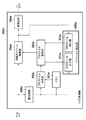
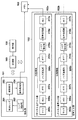
図1は、撮像装置100の構成の一例を示すブロック図である。撮像装置100は、撮像部101、音声入力部102、メモリ103、表示制御部104、表示部105、符号化処理部106、記録再生部107、記録媒体108、制御部109を有する。さらに、撮像装置100は、操作部110、音声出力部111、スピーカ112、外部出力部113、及び、各構成要素を接続するシステムバス114を有する。   FIG. 1 is a block diagram illustrating an example of the configuration of the imaging apparatus 100. The imaging apparatus 100 includes an imaging unit 101, an audio input unit 102, a memory 103, a display control unit 104, a display unit 105, an encoding processing unit 106, a recording / playback unit 107, a recording medium 108, and a control unit 109. Furthermore, the imaging apparatus 100 includes an operation unit 110, an audio output unit 111, a speaker 112, an external output unit 113, and a system bus 114 that connects each component.

撮像部101は、被写体の光学像を画像信号に変換し、これに対して画像処理を行い、画像データを生成する。音声入力部102は、撮像装置100の周辺の音声を集音し、これに対して音声処理を行い、音声データを生成する。   The imaging unit 101 converts an optical image of a subject into an image signal, performs image processing on the image signal, and generates image data. The sound input unit 102 collects sound around the imaging apparatus 100, performs sound processing on the sound, and generates sound data.

メモリ103は、撮像部101から供給される画像データや、音声入力部102から供給される音声データを記憶する。表示制御部104は、撮像部101から得られた画像データや撮像装置100のメニュー画面等を表示部105に表示させる。符号化処理部106は、メモリ103に記憶された画像データに対して所定の符号化を行い、圧縮画像データを生成する。また、符号化処理部106は、メモリ103に記憶された音声データに対して所定の符号化を行い、圧縮音声データを生成する。記録再生部107は、符号化処理部106で生成された圧縮画像データ、圧縮音声データ及び圧縮された動画データの少なくとも一つを記録媒体108に記録する。また、記録再生部107は、記録媒体108に記録されている画像データ、音声データ及び動画データの少なくとも一つを記録媒体108から読み出す。   The memory 103 stores image data supplied from the imaging unit 101 and audio data supplied from the audio input unit 102. The display control unit 104 causes the display unit 105 to display the image data obtained from the imaging unit 101, the menu screen of the imaging device 100, and the like. The encoding processing unit 106 performs predetermined encoding on the image data stored in the memory 103 to generate compressed image data. In addition, the encoding processing unit 106 performs predetermined encoding on the audio data stored in the memory 103 to generate compressed audio data. The recording / reproducing unit 107 records at least one of the compressed image data, the compressed audio data, and the compressed moving image data generated by the encoding processing unit 106 on the recording medium 108. The recording / reproducing unit 107 reads at least one of image data, audio data, and moving image data recorded on the recording medium 108 from the recording medium 108.

制御部109は、システムバス114を介して撮像装置100の各部を制御する。制御部109は、CPU及びメモリを有する。制御部109のメモリには、撮像装置100の各部を制御するためのプログラムが記録される。   The control unit 109 controls each unit of the imaging apparatus 100 via the system bus 114. The control unit 109 has a CPU and a memory. A program for controlling each unit of the imaging apparatus 100 is recorded in the memory of the control unit 109.

操作部110は、ユーザからの指示を撮像装置100に入力するための操作を受け付ける。操作部110は、ユーザによって行われた特定の操作に対応する信号を制御部109に送信する。操作部110は、静止画の撮影を指示するボタン、動画記録開始と停止を指示する記録ボタン、光学的に画像に対してズーム動作を行うように撮像装置100に指示するためのズームボタンなどを有する。さらに、操作部110は、撮像装置100の動作モードを静止画撮影モード、動画撮影モード及び再生モードのなかから選択するためのモード選択ボタンを有する。   The operation unit 110 receives an operation for inputting an instruction from the user to the imaging apparatus 100. The operation unit 110 transmits a signal corresponding to a specific operation performed by the user to the control unit 109. The operation unit 110 includes a button for instructing photographing of a still image, a recording button for instructing start and stop of moving image recording, a zoom button for instructing the imaging apparatus 100 to optically perform a zoom operation on the image, and the like. Have. Furthermore, the operation unit 110 includes a mode selection button for selecting an operation mode of the imaging apparatus 100 from among a still image shooting mode, a moving image shooting mode, and a playback mode.

音声出力部111は、記録再生部107によって読み出された音声データをスピーカ112に出力する。外部出力部113は、記録再生部107によって読み出された音声データを外部機器に出力する。   The audio output unit 111 outputs the audio data read by the recording / reproducing unit 107 to the speaker 112. The external output unit 113 outputs the audio data read by the recording / playback unit 107 to an external device.

次に、撮像装置100が動画撮影モードである場合における動作について説明する。撮像装置100が動画撮影モードである場合、制御部109は、操作部110の記録ボタンがONにされたことに応じて、所定のフレームレートで撮像するように撮像部101を制御し、音声データを取得するように音声入力部102を制御する。この場合、撮像部101で撮像された画像データと音声データとは圧縮され、記録再生部107によって記録媒体108に動画データとして記録される。その後、制御部109は、操作部110の記録ボタンがOFFにされたことに応じて、記録媒体108に記録していた動画データをクローズ処理し、1つの動画ファイルを生成する。なお、撮像装置100が動画撮影モードである場合、ユーザによって操作部110の記録ボタンがONされるまでは、操作部110の記録ボタンは、OFFであるものとする。   Next, an operation when the imaging apparatus 100 is in the moving image shooting mode will be described. When the image capturing apparatus 100 is in the moving image capturing mode, the control unit 109 controls the image capturing unit 101 to capture images at a predetermined frame rate in response to the recording button of the operation unit 110 being turned on, and the audio data The voice input unit 102 is controlled so as to acquire. In this case, the image data and audio data captured by the imaging unit 101 are compressed and recorded as moving image data on the recording medium 108 by the recording / reproducing unit 107. Thereafter, the control unit 109 closes the moving image data recorded on the recording medium 108 in response to the recording button of the operation unit 110 being turned off, and generates one moving image file. When the imaging apparatus 100 is in the moving image shooting mode, it is assumed that the recording button of the operation unit 110 is OFF until the recording button of the operation unit 110 is turned ON by the user.

図20は、撮像部101と音声入力部102との関係を示す。
撮像部101は、光学レンズ201、撮像素子202、レンズ制御部203及び画像処理部204を有する。
光学レンズ201は、被写体に対して光学的に合焦させるためのフォーカスレンズやズームレンズ等である。光学レンズ201は、ズーミングを光学的に行うことができる。以下、光学レンズ201を使ってズーミングを光学的に行うことを「ズーム動作」と呼ぶ。ズーム動作は、制御部109からの指示で、レンズ制御部203が、光学レンズ201を移動させることで、被写体の光学像をズーミングさせるものである。撮像素子202は、被写体の光学像を画像信号に変換し、画像信号を出力する。レンズ制御部203は、光学レンズ201を移動させるためのモータ等を駆動させる。画像処理部204は、撮像素子202から出力される画像信号に対して画像処理を行い、画像データを生成する。
FIG. 20 shows the relationship between the imaging unit 101 and the audio input unit 102.
The imaging unit 101 includes an optical lens 201, an imaging element 202, a lens control unit 203, and an image processing unit 204.
The optical lens 201 is a focus lens or a zoom lens for optically focusing on a subject. The optical lens 201 can perform zooming optically. Hereinafter, the optical zooming using the optical lens 201 is referred to as “zoom operation”. In the zoom operation, the lens control unit 203 moves the optical lens 201 in response to an instruction from the control unit 109 to zoom the optical image of the subject. The image sensor 202 converts an optical image of a subject into an image signal and outputs the image signal. The lens control unit 203 drives a motor or the like for moving the optical lens 201. The image processing unit 204 performs image processing on the image signal output from the image sensor 202 to generate image data.

例えば、ズーム動作やフォーカス調整等を撮像装置100に開始させるための指示が操作部110を介して入力された場合、制御部109は、光学レンズ201を移動させるようにレンズ制御部203を制御するためのズーム制御信号をONに変更する。ズーム制御信号がONに変更された場合、レンズ制御部203は、モータ等を駆動し、光学レンズ201を移動させる。   For example, when an instruction for causing the imaging apparatus 100 to start zoom operation, focus adjustment, or the like is input via the operation unit 110, the control unit 109 controls the lens control unit 203 to move the optical lens 201. The zoom control signal for turning on is changed to ON. When the zoom control signal is changed to ON, the lens control unit 203 drives a motor or the like to move the optical lens 201.

光学レンズ201を移動させる場合、撮像装置100において、光学レンズ201の移動に伴うノイズや光学レンズ201を移動させるためのモータの駆動に伴うノイズが発生する。以下、光学レンズ201の移動に伴うノイズや光学レンズ201を移動させるためのモータの駆動に伴うノイズを「駆動ノイズ」と呼ぶ。   When the optical lens 201 is moved, in the imaging apparatus 100, noise accompanying movement of the optical lens 201 and noise accompanying driving of a motor for moving the optical lens 201 are generated. Hereinafter, the noise accompanying the movement of the optical lens 201 and the noise accompanying the driving of the motor for moving the optical lens 201 are referred to as “driving noise”.

なお、図20において、撮像装置100に光学レンズ201やレンズ制御部203が含まれているものとして説明を行ったが、これに限られないものとする。光学レンズ201やレンズ制御部203は、撮像装置100に対して着脱可能なものであっても良い。   In FIG. 20, the imaging apparatus 100 has been described as including the optical lens 201 and the lens control unit 203, but is not limited thereto. The optical lens 201 and the lens control unit 203 may be detachable from the imaging apparatus 100.

撮像装置100の音声入力部102は、ステレオ録音を実現するため、R(Right)チャネル音声入力部102a及びL(Left)チャネル音声入力部102bを有する。Rチャネル音声入力部102aと、Lチャネル音声入力部102bとは構成が同じであるため、以下、Rチャネル音声入力部102aの構成について説明する。Rチャネル音声入力部102aは、マイク205a、ADC206a、FFT207a、ノイズ低減部200a、IFFT214a、ノイズ印加部215a、音声処理部216a、ALC217aを有する。なお、Rチャネルを以下「Rch」と呼び、Lチャネルを以下「Lch」と呼ぶ。   The audio input unit 102 of the imaging apparatus 100 includes an R (Right) channel audio input unit 102a and an L (Left) channel audio input unit 102b in order to realize stereo recording. Since the R channel audio input unit 102a and the L channel audio input unit 102b have the same configuration, the configuration of the R channel audio input unit 102a will be described below. The R channel audio input unit 102a includes a microphone 205a, an ADC 206a, an FFT 207a, a noise reduction unit 200a, an IFFT 214a, a noise application unit 215a, an audio processing unit 216a, and an ALC 217a. The R channel is hereinafter referred to as “Rch”, and the L channel is hereinafter referred to as “Lch”.

マイク205aは、音声振動を電気信号に変換し、アナログの音声信号を出力する。ADC(アナログデジタルコンバータ)206aは、マイク205aにより得られたアナログ音声信号をデジタル音声信号に変換する。例えば、ADC206aのサンプリング周波数は48KHzで、1サンプルにつき16ビットの、時系列のデジタルデータを出力する。FFT(高速フーリエ変換器)207aは、ADC206aから出力された、例えば、1024個の時系列に並んだ音声データを1フレームとして入力する。そして、FFT207aは、1フレーム分の音声データに対して高速フーリエ変換し、各周波数毎の振幅レベル(振幅スペクトルデータ)を生成し、ノイズ低減部200aに供給する。なお、FFT207aが生成する振幅スペクトルは、0乃至48KHzまでの1024ポイントの各周波数毎の振幅データで構成されるものとする。また、実施形態では1フレームの音声データを1024個としているが、次に処理する1フレームにおける前半の512個のデータと、直前の1フレームの後半の512個のデータは同じであり、互いに一部が重複している。   The microphone 205a converts audio vibration into an electrical signal and outputs an analog audio signal. The ADC (analog / digital converter) 206a converts the analog audio signal obtained by the microphone 205a into a digital audio signal. For example, the sampling frequency of the ADC 206a is 48 KHz, and 16-bit time-series digital data is output per sample. An FFT (Fast Fourier Transformer) 207a inputs, for example, 1024 time-series audio data output from the ADC 206a as one frame. Then, the FFT 207a performs fast Fourier transform on the audio data for one frame, generates an amplitude level (amplitude spectrum data) for each frequency, and supplies it to the noise reduction unit 200a. Note that the amplitude spectrum generated by the FFT 207a is composed of amplitude data for each frequency of 1024 points from 0 to 48 KHz. In the embodiment, the number of audio data of one frame is 1024, but the first half of 512 data in one frame to be processed next and the latter half of 512 data in the immediately preceding frame are the same, and are identical to each other. The parts are overlapping.

ノイズ低減部200aは、ズーム動作を撮像装置100が実行している場合に発生する駆動ノイズを表す周波数毎のノイズの振幅データを、FFT207aから出力された該当する周波数の振幅データから減算する。ノイズ低減部200aは、減算が行われた後の振幅スペクトルデータをIFFT(逆高速フーリエ変換器)214aに供給する。   The noise reduction unit 200a subtracts the amplitude data of the noise for each frequency representing the driving noise generated when the imaging apparatus 100 performs the zoom operation from the amplitude data of the corresponding frequency output from the FFT 207a. The noise reduction unit 200a supplies the amplitude spectrum data after the subtraction to an IFFT (Inverse Fast Fourier Transform) 214a.

IFFT(逆高速フーリエ変換器)214aは、FFT207aから供給された位相情報を用いて、ノイズ低減部200aから供給された振幅スペクトルに対して逆高速フーリエ変換(逆変換)を行うことで、元の時系列形式の音声データを生成する。IFFT214aは、FFT207aにて高速フーリエ変換される前の位相情報を使って時系列の音声信号に戻す。   The IFFT (Inverse Fast Fourier Transform) 214a uses the phase information supplied from the FFT 207a to perform an inverse fast Fourier transform (inverse transform) on the amplitude spectrum supplied from the noise reduction unit 200a, thereby Generate audio data in time series format. The IFFT 214a uses the phase information before being subjected to the fast Fourier transform in the FFT 207a to return it to a time-series audio signal.

ノイズ印加部215aは、IFFT214aから供給される時系列の音声信号に対してノイズ信号を印加する。ノイズ印加部215aによって印加されるノイズ信号は、ノイズフロアレベルの信号であるものとする。音声処理部216aは、風騒音を低減するための処理、ステレオ感を強調するための処理やイコライザ処理等を行う。そして、ALC(オートゲインコントローラ)217aは、時系列の音声信号の振幅を所定のレベルに調整し、調整後の音声データをメモリ103に出力する。   The noise applying unit 215a applies a noise signal to the time-series audio signal supplied from the IFFT 214a. It is assumed that the noise signal applied by the noise applying unit 215a is a noise floor level signal. The sound processing unit 216a performs processing for reducing wind noise, processing for enhancing a stereo feeling, equalizer processing, and the like. The ALC (auto gain controller) 217 a adjusts the amplitude of the time-series audio signal to a predetermined level and outputs the adjusted audio data to the memory 103.

次に、実施形態におけるRチャネル音声入力部102aのノイズ低減部200aについて、図2を用いて、以下説明を行う。   Next, the noise reduction unit 200a of the R channel audio input unit 102a in the embodiment will be described below with reference to FIG.

図2は、ノイズ低減部200aの構成の一例を示すブロック図である。ノイズ低減部200aは、積分回路250a、メモリ251a、プロファイル作成部252a、プロファイル格納部253a、振幅スペクトル減算部254a、後処理部255a、及びプロファイル補正部256aを有する。   FIG. 2 is a block diagram illustrating an example of the configuration of the noise reduction unit 200a. The noise reduction unit 200a includes an integration circuit 250a, a memory 251a, a profile creation unit 252a, a profile storage unit 253a, an amplitude spectrum subtraction unit 254a, a post-processing unit 255a, and a profile correction unit 256a.

ノイズ低減部200aは、撮像装置100がズーム動作を行っている場合に発生する駆動ノイズを低減するための動作を行う。以下、ノイズ低減部200aによって行われる動作について図4を参照し、説明を行う。
図4は、撮像装置100によってズーム動作が行われる前と撮像装置100によってズーム動作が行われている間とにおける周波数毎の振幅スペクトルの一例を表す図である。図4における横軸が周波数を示し、0乃至48Khzの区間の1024ポイントを示している(ただし、ナイキスト周波数である24kHzまでにおいては512ポイントの周波数スペクトルをもつものとする)。図4における401は、撮像装置100がズーム動作を行う前(光学レンズ201が移動していない状態)における環境音を示す振幅スペクトルを示す。図4における402は、撮像装置100がズーム動作を行っている場合(光学レンズ201が移動している状態)における環境音を示す振幅スペクトルを示している。402によって示されている振幅スペクトルには、駆動ノイズが含まれている。ノイズ低減部200aは、401によって示されている振幅スペクトルと、402によって示されている振幅スペクトルとの差分から駆動ノイズを低減するために用いられるノイズプロファイルを作成する。以下、ノイズ低減部200aの各部について説明を行う。
The noise reduction unit 200a performs an operation for reducing drive noise that occurs when the imaging apparatus 100 performs a zoom operation. Hereinafter, the operation performed by the noise reduction unit 200a will be described with reference to FIG.
FIG. 4 is a diagram illustrating an example of an amplitude spectrum for each frequency before the zoom operation is performed by the imaging apparatus 100 and during the zoom operation is performed by the imaging apparatus 100. The horizontal axis in FIG. 4 indicates the frequency and indicates 1024 points in the interval from 0 to 48 Khz (provided that the Nyquist frequency of up to 24 kHz has a 512-point frequency spectrum). Reference numeral 401 in FIG. 4 indicates an amplitude spectrum indicating environmental sound before the imaging apparatus 100 performs a zoom operation (in a state where the optical lens 201 is not moved). Reference numeral 402 in FIG. 4 indicates an amplitude spectrum indicating environmental sound when the imaging apparatus 100 is performing a zoom operation (a state in which the optical lens 201 is moving). The amplitude spectrum indicated by 402 includes drive noise. The noise reduction unit 200a creates a noise profile that is used to reduce drive noise from the difference between the amplitude spectrum indicated by 401 and the amplitude spectrum indicated by 402. Hereinafter, each part of the noise reduction unit 200a will be described.

積分回路250aは、制御部109からの指示に応じて、FFT207aにて高速フーリエ変換された振幅スペクトルの各周波数毎の振幅値を時間軸に積分する。このとき、積分回路250aは、積分したフレーム数をカウントする。FFT207aからの1フレームから得られた振幅スペクトルデータにおける周波数fi(ただし、i=0、1、…、1023のいずれか)の振幅値をA(fi)と表す。この場合、積分回路250aは、次式のように各周波数毎の積分値(累積加算値)S(fi)を求める。
S(fi)=ΣA(fi)
In response to an instruction from the control unit 109, the integration circuit 250a integrates the amplitude value for each frequency of the amplitude spectrum subjected to the fast Fourier transform by the FFT 207a on the time axis. At this time, the integration circuit 250a counts the number of integrated frames. The amplitude value of the frequency fi (where i = 0, 1,..., 1023) in the amplitude spectrum data obtained from one frame from the FFT 207a is represented as A (fi). In this case, the integration circuit 250a obtains an integral value (cumulative addition value) S (fi) for each frequency as in the following equation.
S (fi) = ΣA (fi)

レンズ制御部203が光学レンズ201を移動させていない場合、積分回路250aは、上述のように各周波数の振幅値を積分していく。そして、積分回路250aは、各周波数の積分値を、積分期間を表すフレーム数nで除算した結果を出力する。つまり、積分回路250aは、次式のように周波数毎の平均振幅値Aave(fi)を算出(演算)し、その算出結果を出力する。
Aave(fi)=S(fi)/n
平均振幅値Aave(fi)(i=0、1、…、1023)で示されるデータは、図4の401によって示されている振幅スペクトルに対応する。積分回路250aは、算出した平均振幅値Aave(fi)をメモリ251aに格納する。
When the lens control unit 203 has not moved the optical lens 201, the integration circuit 250a integrates the amplitude value of each frequency as described above. Then, the integration circuit 250a outputs a result obtained by dividing the integration value of each frequency by the number of frames n representing the integration period. That is, the integration circuit 250a calculates (calculates) the average amplitude value Aave (fi) for each frequency as in the following equation, and outputs the calculation result.
Aave (fi) = S (fi) / n
The data indicated by the average amplitude value Aave (fi) (i = 0, 1,..., 1023) corresponds to the amplitude spectrum indicated by 401 in FIG. The integrating circuit 250a stores the calculated average amplitude value Aave (fi) in the memory 251a.

積分回路250aは、レンズ制御部203が光学レンズ201の移動を開始させてから安定化期間が経過するまでの間、上述のように各周波数の振幅値を積分していく。安定化期間とは、積分回路250aの時定数により積分回路250aに入力される振幅スペクトルが安定するまでの期間である。安定化期間が経過するまでの間において、FFT207aから出力される振幅スペクトルには、駆動ノイズが含まれている。安定化期間(例えば、mフレーム分に相当するものとする)が経過した場合、積分回路250aは、S(fi)/mをプロファイル作成部252aに出力する。S(fi)/mは、図4の402によって示されている振幅スペクトルに対応する。   The integration circuit 250a integrates the amplitude value of each frequency as described above from when the lens control unit 203 starts moving the optical lens 201 until the stabilization period elapses. The stabilization period is a period until the amplitude spectrum input to the integration circuit 250a is stabilized by the time constant of the integration circuit 250a. Until the stabilization period elapses, the amplitude spectrum output from the FFT 207a includes drive noise. When a stabilization period (for example, corresponding to m frames) has elapsed, the integration circuit 250a outputs S (fi) / m to the profile creation unit 252a. S (fi) / m corresponds to the amplitude spectrum indicated by 402 in FIG.

プロファイル作成部252aは、積分回路250aから供給されたS(fi)/mからメモリ251aに格納されたS(fi)/nを減算することで、各周波数毎の駆動ノイズに対応する振幅値であるN(fi)を次式のように算出する。
N(fi)=S(fi)/m−S(fi)/n
The profile creation unit 252a subtracts S (fi) / n stored in the memory 251a from S (fi) / m supplied from the integration circuit 250a, thereby obtaining an amplitude value corresponding to driving noise for each frequency. A certain N (fi) is calculated as follows.
N (fi) = S (fi) / m-S (fi) / n

N(fi)が算出された後、プロファイル作成部252aは、N(fi)をノイズプロファイルとしてプロファイル格納部253aに格納する。ノイズプロファイルとは、ズーム動作が行われている場合に発生する駆動ノイズを示すデータである。   After N (fi) is calculated, the profile creation unit 252a stores N (fi) as a noise profile in the profile storage unit 253a. The noise profile is data indicating drive noise that occurs when a zoom operation is performed.

その後、振幅スペクトル減算部254aは、FFT207aから供給される振幅スペクトルのA(fi)から、プロファイル格納部253aから読み出された駆動ノイズの振幅値N(fi)を減算する処理を行う。なお、以下、FFT207aから供給される振幅スペクトルのA(fi)から、プロファイル格納部253aから読み出されたノイズプロファイルである振幅値N(fi)を減算する処理を「減算処理」と呼ぶ。振幅スペクトル減算部254aは、次式によって得られた振幅スペクトルANR(fi)をIFFT214aまたはIFFT214bに出力する。
NR(fi)=A(fi)−N(fi)
After that, the amplitude spectrum subtraction unit 254a performs a process of subtracting the drive noise amplitude value N (fi) read from the profile storage unit 253a from the amplitude spectrum A (fi) supplied from the FFT 207a. Hereinafter, the process of subtracting the amplitude value N (fi), which is the noise profile read from the profile storage unit 253a, from A (fi) of the amplitude spectrum supplied from the FFT 207a is referred to as “subtraction process”. The amplitude spectrum subtraction unit 254a outputs the amplitude spectrum A NR (fi) obtained by the following equation to the IFFT 214a or the IFFT 214b.
A NR (fi) = A (fi) −N (fi)

なお、ユーザによって撮像装置100へのズーム動作の開始の指示を受けてから安定化期間が経過するまでの間、プロファイル作成部252aによってノイズプロファイルの作成が完了していない状態が発生する。これにより、プロファイル作成部252aによるノイズプロファイルの作成が完了するまでの期間を短くするためには、「m」を小さくする必要がある。しかし、「m」が極端に小さい場合、ノイズプロファイルによる駆動ノイズの低減の精度が低くなってしまう可能性がある。レンズ制御部203が光学レンズ201を移動させるための制御を開始した場合、70ms程度の間、駆動ノイズの一種である光学レンズ201の動きだし音、音揺れ等が発生する。光学レンズ201の動きだし音、音揺れ等を低減するために、70msを超える期間において、プロファイル作成部252aにノイズプロファイルを作成させるため、「m」を例えば「15」とする。   It should be noted that a state in which the creation of the noise profile is not completed by the profile creation unit 252a occurs after the stabilization period elapses after the user receives an instruction to start the zoom operation to the imaging apparatus 100. Thereby, in order to shorten the period until the creation of the noise profile by the profile creation unit 252a is completed, it is necessary to reduce “m”. However, when “m” is extremely small, there is a possibility that the drive noise reduction accuracy by the noise profile is lowered. When the lens control unit 203 starts control for moving the optical lens 201, a movement sound, sound vibration, and the like of the optical lens 201, which are a kind of driving noise, are generated for about 70 ms. In order to reduce the starting sound and vibration of the optical lens 201, “m” is set to, for example, “15” in order to cause the profile creation unit 252a to create a noise profile in a period exceeding 70 ms.

実施形態では、1フレームは1024個の時系列の音声データであるものの各フレームの半分は互いに重畳している。また、音声データのサンプリングレートは48kHzとしているので、m=15とすると、ノイズプロファイルの作成期間Tは、
T=mフレーム分の期間=m×(1024/2)/48kHz=160ms
となる。ユーザによって撮像装置100へのズーム動作の開始の指示を受けてから作成期間Tが経過するまでの間に、プロファイル作成部252aは、ノイズプロファイルを作成する。このため、プロファイル作成部252aは、光学レンズ201の動きだし音、音揺れ等を低減するための精度の高いノイズプロファイルを作成できる。
In the embodiment, although one frame is 1024 time-series audio data, half of each frame is superimposed on each other. Since the sampling rate of the audio data is 48 kHz, if m = 15, the noise profile creation period T is
T = m frame period = m × (1024/2) / 48 kHz = 160 ms
It becomes. The profile creation unit 252a creates a noise profile during the period from when the user receives an instruction to start the zoom operation to the imaging apparatus 100 until the creation period T elapses. For this reason, the profile creation unit 252a can create a highly accurate noise profile for reducing the movement sound and sound fluctuation of the optical lens 201.

後処理部255aは、振幅スペクトル減算部254aによって減算処理が行われた後の振幅スペクトルを補正して、IFFT214aに出力する。   The post-processing unit 255a corrects the amplitude spectrum after the subtraction process is performed by the amplitude spectrum subtracting unit 254a and outputs the corrected amplitude spectrum to the IFFT 214a.

プロファイル補正部256aは、環境音の大きさに応じて、プロファイル格納部253aに格納されたノイズプロファイルを補正する処理を行う。プロファイル補正部256aによって行われるノイズプロファイルの補正として、拡大補正(増加補正)と縮小補正(減少補正)とがある。プロファイル補正部256aは、ノイズプロファイルの拡大補正を行うプロファイル拡大部271aと、ノイズプロファイルの縮小補正を行うプロファイル縮小部272aとを有する。   The profile correction unit 256a performs a process of correcting the noise profile stored in the profile storage unit 253a according to the magnitude of the environmental sound. As correction of the noise profile performed by the profile correction unit 256a, there are enlargement correction (increase correction) and reduction correction (decrease correction). The profile correction unit 256a includes a profile enlargement unit 271a that performs noise profile enlargement correction and a profile reduction unit 272a that performs noise profile reduction correction.

ノイズプロファイルの拡大補正とは、プロファイル作成部252aによって作成されたノイズプロファイルまたはプロファイル補正部256aによって補正されたノイズプロファイルの振幅スペクトルを増大させる補正である。つまり、ノイズプロファイルの拡大補正をすることで振幅スペクトル減算部254aによって減算処理がされた後の振幅スペクトルANR(fi)は小さくなる。また、ノイズプロファイルの縮小補正とは、プロファイル作成部252aによって作成されたノイズプロファイルまたはプロファイル補正部256aによって補正されたノイズプロファイルの振幅スペクトルを減少させる補正である。つまり、ノイズプロファイルの縮小補正をすることで振幅スペクトル減算部211によって減算処理がされた後の振幅スペクトルANR(fi)は大きくなる。プロファイル補正部256aによって行われるノイズプロファイルの補正は必要に応じて、FFT207aから供給される1フレーム毎の振幅スペクトルA(fi)に対して行われる。撮像装置100によってズーム動作が行われている場合、環境音や駆動ノイズの変動に応じて、プロファイル補正部256aは、ノイズプロファイルを適正に補正することができる。 The noise profile enlargement correction is correction for increasing the amplitude spectrum of the noise profile created by the profile creation unit 252a or the noise profile corrected by the profile correction unit 256a. That is, the amplitude spectrum A NR (fi) after the subtraction process is performed by the amplitude spectrum subtracting unit 254a is reduced by performing the correction of the noise profile. The noise profile reduction correction is correction for reducing the amplitude profile of the noise profile created by the profile creation unit 252a or the noise profile corrected by the profile correction unit 256a. That is, the amplitude spectrum A NR (fi) after the subtraction process is performed by the amplitude spectrum subtracting unit 211 is increased by performing the noise profile reduction correction. The noise profile correction performed by the profile correction unit 256a is performed on the amplitude spectrum A (fi) for each frame supplied from the FFT 207a as necessary. When the zoom operation is performed by the imaging apparatus 100, the profile correction unit 256a can appropriately correct the noise profile in accordance with fluctuations in environmental sound and driving noise.

Lチャネル音声入力部102bもRチャネル音声入力部102aと同様に、マイク205b、ADC206b、FFT207b、ノイズ低減部200b、IFFT214b、ノイズ印加部215b、音声処理部216b、ALC217bを有する。マイク205aとマイク205bとは、同様の構成であり、FFT207aとFFT207bとは、同様の構成であり、ノイズ低減部200aとノイズ低減部200bは、同様の構成である。さらに、IFFT214aとIFFT214bとは、同様の構成であり、ノイズ印加部215aとノイズ印加部215bとは、同様の構成である。さらに、音声処理部216aと音声処理部216bとは、同様の構成であり、ALC217aとALC217bとは同様の構成である。   Similarly to the R channel audio input unit 102a, the L channel audio input unit 102b includes a microphone 205b, an ADC 206b, an FFT 207b, a noise reduction unit 200b, an IFFT 214b, a noise application unit 215b, an audio processing unit 216b, and an ALC 217b. The microphone 205a and the microphone 205b have the same configuration, the FFT 207a and the FFT 207b have the same configuration, and the noise reduction unit 200a and the noise reduction unit 200b have the same configuration. Furthermore, IFFT 214a and IFFT 214b have the same configuration, and noise application unit 215a and noise application unit 215b have the same configuration. Furthermore, the audio processing unit 216a and the audio processing unit 216b have the same configuration, and the ALC 217a and the ALC 217b have the same configuration.

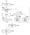
図3は、撮像装置100のモードとして動画撮影モードが選択された場合に制御部109によって行われる動画記録処理の一例を示すフローチャートである。マイク205aからADC206aにアナログの音声信号が出力される場合を一例に挙げて、以下、動画記録処理について説明する。   FIG. 3 is a flowchart illustrating an example of a moving image recording process performed by the control unit 109 when the moving image shooting mode is selected as the mode of the imaging apparatus 100. The moving image recording process will be described below by taking an example in which an analog audio signal is output from the microphone 205a to the ADC 206a.

撮像装置100が動画撮影モードに変更された場合、制御部109は、ノイズ低減部200aにおけるプロファイル格納部253aをゼロクリアにする(S301)。その後、制御部109は、積分回路250aに対してFFT207aから入力された振幅スペクトルの積分処理を開始させる(S302)。そして、制御部109は、操作部110の記録ボタンがONされたか否か、つまり動画データの記録を撮像装置100に開始させる指示が入力されたか否かを判定する(S303)。動画データの記録を撮像装置100に開始させる指示が入力された場合(S303でYes)、制御部109は、動画データの記録を開始する(S304)。この場合、制御部109は、撮像部101及び音声入力部102からメモリ103に格納される動画データを生成するための画像データ及び音声データの符号化処理を開始し、記録再生部107に記録媒体108への記録を開始させる。   When the imaging apparatus 100 is changed to the moving image shooting mode, the control unit 109 clears the profile storage unit 253a in the noise reduction unit 200a to zero (S301). Thereafter, the control unit 109 causes the integrating circuit 250a to start integrating the amplitude spectrum input from the FFT 207a (S302). Then, the control unit 109 determines whether or not the recording button of the operation unit 110 is turned on, that is, whether or not an instruction for starting the recording of moving image data to the imaging device 100 is input (S303). When an instruction to start recording moving image data is input to the imaging apparatus 100 (Yes in S303), the control unit 109 starts recording moving image data (S304). In this case, the control unit 109 starts encoding processing of image data and audio data for generating moving image data stored in the memory 103 from the imaging unit 101 and the audio input unit 102, and stores the recording medium in the recording / playback unit 107. Recording to 108 is started.

S305では、制御部109は、操作部110を介してズーム動作を開始する指示が入力されたか否かを判定する。操作部110を介してズーム動作を開始する指示が入力されなかった場合、制御部109は、操作部110を介して動画データの記録を撮像装置100に終了させる指示が入力されたか否かを判定する(S306)。操作部110を介して動画データの記録を撮像装置100に終了させる指示が入力された場合(S306でYes)、制御部109は、メモリ103に格納されている動画データの符号化を開始し、記録媒体108への記録を行わせる。さらに、制御部109は、記録媒体108に格納されている動画データのクローズ処理を行い、動画ファイルとして完成させる(S312)。操作部110を介して動画データの記録を撮像装置100に終了させる指示が入力されなかった場合(S306でNo)、処理は、S306からS302に戻る。   In step S <b> 305, the control unit 109 determines whether an instruction to start a zoom operation is input via the operation unit 110. When an instruction to start a zoom operation is not input via the operation unit 110, the control unit 109 determines whether an instruction to end recording of moving image data is input to the imaging apparatus 100 via the operation unit 110. (S306). When an instruction to end recording of moving image data is input to the imaging apparatus 100 via the operation unit 110 (Yes in S306), the control unit 109 starts encoding of moving image data stored in the memory 103, Recording on the recording medium 108 is performed. Further, the control unit 109 performs a closing process on the moving image data stored in the recording medium 108 and completes it as a moving image file (S312). When an instruction to end recording of moving image data is not input to the imaging apparatus 100 via the operation unit 110 (No in S306), the process returns from S306 to S302.

一方、操作部110からズーム動作を開始する指示が入力された場合、処理は、S305からS307に進む。S307において、制御部109は、ノイズ低減部200aにノイズプロファイルを作成させるために、ノイズプロファイル作成処理を行う。S307において行われるノイズプロファイル作成処理については後述する。ノイズプロファイル作成処理が実行されることによって作成されたノイズプロファイルは、プロファイル格納部253aに格納される。   On the other hand, when an instruction to start the zoom operation is input from the operation unit 110, the process proceeds from S305 to S307. In step S307, the control unit 109 performs noise profile creation processing to cause the noise reduction unit 200a to create a noise profile. The noise profile creation process performed in S307 will be described later. The noise profile created by executing the noise profile creation process is stored in the profile storage unit 253a.

次に、制御部109は、FFT207aにて高速フーリエ変換された周波数毎の振幅スペクトルの各周波数毎の振幅値からノイズプロファイルに含まれる特定の周波数の振幅値を減算するノイズ低減処理を行う(S308)。ノイズ低減処理が行われる場合、制御部109は、減算処理を行うように振幅スペクトル減算部254aを制御する。次に、制御部109は、プロファイル格納部210aに格納されたノイズプロファイルを補正するようにプロファイル補正部256aを制御するノイズプロファイル補正処理を行う(S309)。S309において行われるノイズプロファイル補正処理については後述する。プロファイル補正部256aによって補正されたノイズプロファイルは、次フレームの減算処理で適用される。次に、制御部109は、振幅スペクトル減算部254aにより減算処理が行われた後に得られたRchの振幅スペクトルと、振幅スペクトル減算部254bにより減算処理が行われた後に得られたLchの振幅スペクトルとがある場合、後処理を行う(S310)。後処理とは、Rchの振幅スペクトルとLchの振幅スペクトルとを同一にするように補正する処理である。S310において行われる後処理については後述する。   Next, the control unit 109 performs a noise reduction process of subtracting the amplitude value of a specific frequency included in the noise profile from the amplitude value for each frequency of the amplitude spectrum for each frequency that has been fast Fourier transformed by the FFT 207a (S308). ). When the noise reduction process is performed, the control unit 109 controls the amplitude spectrum subtraction unit 254a to perform the subtraction process. Next, the control unit 109 performs a noise profile correction process for controlling the profile correction unit 256a so as to correct the noise profile stored in the profile storage unit 210a (S309). The noise profile correction process performed in S309 will be described later. The noise profile corrected by the profile correction unit 256a is applied in the subtraction process for the next frame. Next, the control unit 109 outputs the Rch amplitude spectrum obtained after the subtraction process is performed by the amplitude spectrum subtraction unit 254a and the Lch amplitude spectrum obtained after the subtraction process is performed by the amplitude spectrum subtraction unit 254b. If so, post-processing is performed (S310). The post-processing is a process of correcting the Rch amplitude spectrum and the Lch amplitude spectrum to be the same. The post-processing performed in S310 will be described later.

そして、操作部110からズーム動作を停止する指示が入力されたか否かが判定される(S311)。操作部110からズーム動作を停止する指示が入力されていない場合、撮像装置100においてズーム動作が継続して実行されるので、制御部109は、S308からS310までの処理を繰り返す。また、制御部109は、操作部110からズーム動作を停止する指示が入力された場合、撮像装置100におけるズーム動作を停止し、S301の処理に戻る。   Then, it is determined whether or not an instruction to stop the zoom operation is input from the operation unit 110 (S311). When an instruction to stop the zoom operation is not input from the operation unit 110, the zoom operation is continuously executed in the imaging apparatus 100, and thus the control unit 109 repeats the processing from S308 to S310. In addition, when an instruction to stop the zoom operation is input from the operation unit 110, the control unit 109 stops the zoom operation in the imaging apparatus 100 and returns to the process of S301.

なお、図3の動画記録処理について、マイク205aからADC206aにアナログの音声信号が出力される場合を一例に挙げて説明を行った。しかしながら、マイク205bからADC206bにアナログの音声信号が出力される場合も、図3の動画記録処理と同様に動画の記録を行う。   Note that the moving image recording process in FIG. 3 has been described by taking an example in which an analog audio signal is output from the microphone 205a to the ADC 206a. However, even when an analog audio signal is output from the microphone 205b to the ADC 206b, a moving image is recorded in the same manner as the moving image recording process of FIG.

[ノイズプロファイル作成処理(S307)]
S307において制御部109によって実行されるノイズプロファイルの作成処理について図4、5、6及び7を用いて説明を行う。マイク205aからADC206aにアナログの音声信号が出力される場合を一例に挙げて、以下、ノイズプロファイルの作成処理について説明する。
[Noise Profile Creation Processing (S307)]
The noise profile creation process executed by the control unit 109 in S307 will be described with reference to FIGS. The case where an analog audio signal is output from the microphone 205a to the ADC 206a will be described as an example, and the noise profile creation process will be described below.

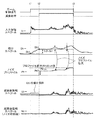
図5は、周波数毎の振幅スペクトルに対するノイズプロファイル作成処理を示すタイミングチャート図である。図6は、撮像装置100によってズーム動作が開始される前における環境音が大きい場合における周波数毎の振幅スペクトルに対するノイズプロファイル作成処理を示すタイミングチャート図である。   FIG. 5 is a timing chart showing a noise profile creation process for the amplitude spectrum for each frequency. FIG. 6 is a timing chart illustrating a noise profile creation process for the amplitude spectrum for each frequency when the environmental sound is large before the zoom operation is started by the imaging apparatus 100.

以下、図5及び6について説明を行う。図5及び6おいて、制御部109が光学レンズ201を移動させるようにレンズ制御部203を制御するタイミングを「t1」とする。制御部109は、光学レンズ201を移動させるようにレンズ制御部203を制御するために、ズーム制御信号をONに変更する。制御部109は、光学レンズ201を移動させるようにレンズ制御部203を制御しない場合、ズーム制御信号をONにしないので、この場合、ズーム制御信号は、OFFになる。また、制御部109は、光学レンズ201の移動を停止させるようにレンズ制御部203を制御する場合、ズーム制御信号をOFFに変更する。ズーム制御信号がONに変更された場合、レンズ制御部203は、光学レンズ201の移動を開始させる。ズーム制御信号がOFFに変更された場合、レンズ制御部203は、光学レンズ201の移動を停止させる。さらに、図5及び6おいて、振幅スペクトル減算部254aにノイズプロファイルを用いた減算処理を開始させるタイミングを「t2」とする。さらに、図5及び6おいて、制御部109がズーム制御信号をOFFにするタイミングを「t3」とする。ノイズプロファイルを用いた減算処理は、タイミングt2からタイミングt3までの期間、振幅スペクトル減算部254aによって行われる。   Hereinafter, FIGS. 5 and 6 will be described. 5 and 6, the timing at which the control unit 109 controls the lens control unit 203 to move the optical lens 201 is “t1”. The control unit 109 changes the zoom control signal to ON in order to control the lens control unit 203 to move the optical lens 201. If the control unit 109 does not control the lens control unit 203 so as to move the optical lens 201, the zoom control signal is not turned on. In this case, the zoom control signal is turned off. In addition, when the control unit 109 controls the lens control unit 203 to stop the movement of the optical lens 201, the control unit 109 changes the zoom control signal to OFF. When the zoom control signal is changed to ON, the lens control unit 203 starts to move the optical lens 201. When the zoom control signal is changed to OFF, the lens control unit 203 stops the movement of the optical lens 201. Further, in FIGS. 5 and 6, the timing at which the amplitude spectrum subtraction unit 254a starts the subtraction process using the noise profile is “t2”. Further, in FIGS. 5 and 6, the timing at which the control unit 109 turns off the zoom control signal is “t3”. The subtraction process using the noise profile is performed by the amplitude spectrum subtraction unit 254a during the period from the timing t2 to the timing t3.

図5及び6において、FFT207aによって高速フーリエ変換された所定の周波数fiの振幅スペクトルを「It」とする。さらに、図5及び6において、積分回路250aによって積分された所定の周波数fiの振幅を示す振幅スペクトルを「Dt」とする。図5及び6において、プロファイル作成部252aによって作成された所定の周波数fiに対応するノイズプロファイルを「Pt」とし、振幅スペクトル減算部254aから出力される所定の周波数fiの振幅スペクトルを「Ut」とする。さらに図5及び6において、ノイズ印加部215aによってノイズ信号が印加された後の所定の周波数fiの時系列のデジタル音声信号を「Nt」とする。   5 and 6, the amplitude spectrum of the predetermined frequency fi that has been fast Fourier transformed by the FFT 207a is assumed to be “It”. Further, in FIGS. 5 and 6, the amplitude spectrum indicating the amplitude of the predetermined frequency fi integrated by the integration circuit 250a is “Dt”. 5 and 6, the noise profile corresponding to the predetermined frequency fi created by the profile creation unit 252a is “Pt”, and the amplitude spectrum of the predetermined frequency fi output from the amplitude spectrum subtraction unit 254a is “Ut”. To do. Further, in FIGS. 5 and 6, a time-series digital audio signal having a predetermined frequency fi after the noise signal is applied by the noise applying unit 215a is represented as “Nt”.

ノイズプロファイルPtは、ナイキスト周波数である24kHzまでにおいて512ポイントの振幅スペクトルを持つ。図5及び6における512ポイントの振幅スペクトルDt1は、撮像装置100がズーム動作を行う前(光学レンズ201が移動していない状態)における環境音を示す振幅スペクトルを示し、図4における401に対応する。図5及び6における512ポイントの振幅スペクトル(Dt2)は、撮像装置100がズーム動作を行っている場合(光学レンズ201が移動している状態)における環境音を示す振幅スペクトルを示し、図4における402に対応する。   The noise profile Pt has an amplitude spectrum of 512 points up to the Nyquist frequency of 24 kHz. A 512-point amplitude spectrum Dt1 in FIGS. 5 and 6 indicates an amplitude spectrum indicating an environmental sound before the imaging apparatus 100 performs a zoom operation (a state in which the optical lens 201 is not moved), and corresponds to 401 in FIG. . A 512-point amplitude spectrum (Dt2) in FIGS. 5 and 6 indicates an amplitude spectrum indicating an environmental sound when the imaging apparatus 100 is performing a zoom operation (a state in which the optical lens 201 is moving). Corresponding to 402.

図7は、制御部109によって行わせるノイズプロファイル作成処理を示すフローチャートである。次に、図7を用いて、制御部109によって行われるノイズプロファイル作成処理について説明する。なお、プロファイル作成部252aがノイズプロファイルを作成する場合を一例に挙げて、以下、ノイズプロファイル作成処理について説明する。操作部110からズーム動作を開始する指示が入力された場合(S305でYes)に、制御部109によってズーム制御信号はOFFからONに変更される(タイミングt1)。タイミングt1において、制御部109は、上述のように、Aave(fi)を算出するように積分回路250aを制御する。積分回路250aによってAave(fi)が算出された場合、制御部109は、Aave(fi)を振幅スペクトルDt1としてメモリ251aに保存する(S701)。   FIG. 7 is a flowchart showing a noise profile creation process to be performed by the control unit 109. Next, the noise profile creation process performed by the control unit 109 will be described with reference to FIG. The case where the profile creating unit 252a creates a noise profile will be described as an example, and the noise profile creating process will be described below. When an instruction to start the zoom operation is input from the operation unit 110 (Yes in S305), the zoom control signal is changed from OFF to ON by the control unit 109 (timing t1). At timing t1, the control unit 109 controls the integration circuit 250a so as to calculate Aave (fi) as described above. When Aave (fi) is calculated by the integrating circuit 250a, the control unit 109 stores Aave (fi) in the memory 251a as the amplitude spectrum Dt1 (S701).

次に、制御部109は、タイミングt1から安定化期間が経過するまで、レンズ制御部203が光学レンズ201を移動させている場合の振幅スペクトルにおける各周波数毎の積分値を取得するように積分回路250aを制御する。その後、制御部109は、安定化期間が経過したか否かを判定する(S702)。安定化期間が経過した場合(タイミングt2)(S702でYes)、制御部109は、上述のように、S(fi)/mを算出するように積分回路250aを制御する。積分回路250aによってS(fi)/mが算出された場合、制御部109は、S(fi)/mを振幅スペクトルDt2としてメモリ251aに保存する(S703)。   Next, the control unit 109 integrates the integration circuit for each frequency in the amplitude spectrum when the lens control unit 203 moves the optical lens 201 until the stabilization period elapses from the timing t1. 250a is controlled. Thereafter, the control unit 109 determines whether or not the stabilization period has elapsed (S702). When the stabilization period has elapsed (timing t2) (Yes in S702), the control unit 109 controls the integration circuit 250a to calculate S (fi) / m as described above. When S (fi) / m is calculated by the integration circuit 250a, the control unit 109 stores S (fi) / m as the amplitude spectrum Dt2 in the memory 251a (S703).

次に、制御部109は、振幅スペクトルDt1が所定の振幅スペクトルであるDtth以下であるか否かを判定する(S704)。所定の振幅スペクトルDtthは、あらかじめメモリ103に格納されているものとする。所定の振幅スペクトルDtthは、撮像装置100によってズーム動作が開始される前における環境音が大きい場合であっても、駆動ノイズを低減できるように設定される。所定の振幅スペクトルDtthは、撮像装置100の騒音ノイズとして予測されるノイズレベルよりも一定レベル低いレベルになるように設定される。   Next, the control unit 109 determines whether or not the amplitude spectrum Dt1 is equal to or less than a predetermined amplitude spectrum Dtth (S704). It is assumed that the predetermined amplitude spectrum Dtth is stored in the memory 103 in advance. The predetermined amplitude spectrum Dtth is set so that driving noise can be reduced even when the environmental sound before the zoom operation is started by the imaging apparatus 100 is loud. The predetermined amplitude spectrum Dtth is set to be a level that is lower than the noise level predicted as noise noise of the imaging apparatus 100 by a certain level.

振幅スペクトルDt1が所定の振幅スペクトルDtthよりも大きいと判定された場合(S704でNo)、制御部109は、ズーム動作が開始される前の環境音が大きいと判定する。振幅スペクトルDt1が所定の振幅スペクトルDtthより大きいと判定された場合(S704でNo)、ノイズプロファイル作成処理は、図6のようなタイミングチャートになる。この場合(S704でNo)、制御部109は、振幅スペクトルDt1としてメモリ251aに保存されているAave(fi)を消去し、所定の振幅スペクトルDtthが振幅スペクトルDt1としてメモリ251aに保存されるようにする(S705)。所定の振幅スペクトルDtthが振幅スペクトルDt1としてメモリ251aに保存された場合、制御部109は、S706の処理を行う。振幅スペクトルDt1が所定の振幅スペクトルDtth以下であると判定された場合(S704でYes)、ノイズプロファイル作成処理は、図5のようなタイミングチャートになる。この場合(S704でYes)、制御部109は、S706の処理を行う。   When it is determined that the amplitude spectrum Dt1 is larger than the predetermined amplitude spectrum Dtth (No in S704), the control unit 109 determines that the environmental sound before the zoom operation is started is large. When it is determined that the amplitude spectrum Dt1 is larger than the predetermined amplitude spectrum Dtth (No in S704), the noise profile creation process is a timing chart as shown in FIG. In this case (No in S704), the control unit 109 deletes Aave (fi) stored in the memory 251a as the amplitude spectrum Dt1 so that the predetermined amplitude spectrum Dtth is stored in the memory 251a as the amplitude spectrum Dt1. (S705). When the predetermined amplitude spectrum Dtth is stored in the memory 251a as the amplitude spectrum Dt1, the control unit 109 performs the process of S706. When it is determined that the amplitude spectrum Dt1 is equal to or less than the predetermined amplitude spectrum Dtth (Yes in S704), the noise profile creation process is a timing chart as shown in FIG. In this case (Yes in S704), the control unit 109 performs the process of S706.

次に、制御部109は、振幅スペクトルDt2から振幅スペクトルDt1を減算することによって、ノイズプロファイルPtを作成するようにプロファイル作成部252aを制御する(S706)。振幅スペクトルDt1が所定の振幅スペクトルDtth以下である場合、プロファイル作成部252aは、振幅スペクトルDt2からAave(fi)を減算することによって、ノイズプロファイルPtを作成する。振幅スペクトルDt1が所定の振幅スペクトルDtthよりも大きい場合、プロファイル作成部252aは、振幅スペクトルDt2から所定の振幅スペクトルDtthを減算することによって、ノイズプロファイルPtを作成する。プロファイル作成部252aによって作成されたノイズプロファイルPtは、プロファイル格納部253aに格納される。   Next, the control unit 109 controls the profile creation unit 252a to create the noise profile Pt by subtracting the amplitude spectrum Dt1 from the amplitude spectrum Dt2 (S706). When the amplitude spectrum Dt1 is equal to or smaller than the predetermined amplitude spectrum Dtth, the profile creation unit 252a creates a noise profile Pt by subtracting Aave (fi) from the amplitude spectrum Dt2. When the amplitude spectrum Dt1 is larger than the predetermined amplitude spectrum Dtth, the profile creation unit 252a creates a noise profile Pt by subtracting the predetermined amplitude spectrum Dtth from the amplitude spectrum Dt2. The noise profile Pt created by the profile creation unit 252a is stored in the profile storage unit 253a.

安定化期間が経過していない場合(S702でNo)、プロファイル格納部253aには、ノイズプロファイルPtは格納されていないので、ノイズプロファイルPtを用いて駆動ノイズを低減することはできない。そこで、制御部109は、振幅スペクトルUtが振幅スペクトルDt1と同一になるように振幅スペクトル減算部254aを制御する。安定化期間が経過していない場合、図5の501のように環境音が途中から急激に変動する場合がある。この場合、制御部109は、振幅スペクトルItが振幅スペクトルDt1以上であるか否かを判定する(S707)。   When the stabilization period has not elapsed (No in S702), since the noise profile Pt is not stored in the profile storage unit 253a, driving noise cannot be reduced using the noise profile Pt. Therefore, the control unit 109 controls the amplitude spectrum subtraction unit 254a so that the amplitude spectrum Ut is the same as the amplitude spectrum Dt1. When the stabilization period has not elapsed, the environmental sound may fluctuate abruptly from the middle as indicated by reference numeral 501 in FIG. In this case, the control unit 109 determines whether or not the amplitude spectrum It is greater than or equal to the amplitude spectrum Dt1 (S707).

振幅スペクトルItが振幅スペクトルDt1以上であると判定された場合(S707でYes)、制御部109は、振幅スペクトルUtが振幅スペクトルDt1と同一になるように振幅スペクトル減算部254aを制御する(S708)。振幅スペクトルItが振幅スペクトルDt1以上であると判定された場合(S707でYes)、安定化期間が経過するまで(タイミングt1からタイミングt2まで)は、振幅スペクトルUtは、振幅スペクトルDt1と同一になるように制御される。振幅スペクトルItが振幅スペクトルDt1以上でないと判定された場合(S707でNo)、制御部109は、振幅スペクトルUtが振幅スペクトルItと同一になるように振幅スペクトル減算部254aを制御する(S709)。振幅スペクトルItが振幅スペクトルDt1よりも小さいと判定された場合(S707でNo)、安定化期間が経過するまで(タイミングt1からタイミングt2まで)、振幅スペクトルUtは、振幅スペクトルItと同一になるように制御される。   When it is determined that the amplitude spectrum It is equal to or greater than the amplitude spectrum Dt1 (Yes in S707), the control unit 109 controls the amplitude spectrum subtracting unit 254a so that the amplitude spectrum Ut is the same as the amplitude spectrum Dt1 (S708). . When it is determined that the amplitude spectrum It is equal to or greater than the amplitude spectrum Dt1 (Yes in S707), the amplitude spectrum Ut is the same as the amplitude spectrum Dt1 until the stabilization period elapses (from timing t1 to timing t2). To be controlled. When it is determined that the amplitude spectrum It is not equal to or greater than the amplitude spectrum Dt1 (No in S707), the control unit 109 controls the amplitude spectrum subtracting unit 254a so that the amplitude spectrum Ut is the same as the amplitude spectrum It (S709). When it is determined that the amplitude spectrum It is smaller than the amplitude spectrum Dt1 (No in S707), the amplitude spectrum Ut is the same as the amplitude spectrum It until the stabilization period elapses (from timing t1 to timing t2). Controlled.

なお、図7のノイズプロファイル作成処理について、プロファイル作成部252aがノイズプロファイルを作成する場合を一例に挙げて説明を行った。しかしながら、プロファイル作成部252bがノイズプロファイルを作成する場合も、図7のノイズプロファイル作成処理と同様にノイズプロファイルを作成する。   Note that the noise profile creation processing in FIG. 7 has been described by taking as an example the case where the profile creation unit 252a creates a noise profile. However, even when the profile creation unit 252b creates a noise profile, it creates a noise profile in the same manner as the noise profile creation processing of FIG.

なお、図6のような場合、振幅スペクトルItが振幅スペクトルDt1以上の状態になったり、振幅スペクトルItが振幅スペクトルDt1よりも小さい状態になったりを繰り返す場合がある。このような場合であっても、振幅スペクトルUtは、振幅スペクトルDt1を超えないように制御される。これにより、撮像装置100は、安定化期間が経過するまで(タイミングt1からタイミングt2まで)の期間において、駆動ノイズを低減することができる。   In the case shown in FIG. 6, the amplitude spectrum It may be in a state equal to or greater than the amplitude spectrum Dt1, or the amplitude spectrum It may be smaller than the amplitude spectrum Dt1. Even in such a case, the amplitude spectrum Ut is controlled so as not to exceed the amplitude spectrum Dt1. Thereby, the imaging device 100 can reduce drive noise during a period until the stabilization period elapses (from timing t1 to timing t2).

このように、ズーム制御信号がONにされてから安定化期間が経過するまで(タイミングt1からタイミングt2まで)の期間、制御部109は、振幅スペクトルUtが振幅スペクトルItまたは振幅スペクトルDt1になるように制御する。これにより、撮像装置100は、ズーム制御信号がONにされてから安定化期間が経過するまで(タイミングt1からタイミングt2まで)の期間における駆動ノイズを低減することができる。さらに、安定化期間が経過した後(タイミングt2からタイミングt3まで)の期間、制御部109は、ノイズプロファイルPtを使って、安定化期間が経過した後(タイミングt2からタイミングt3まで)の期間における駆動ノイズを低減することができる。これにより、撮像装置100は、駆動ノイズの低減をシームレスに行うことができる。   As described above, during the period from when the zoom control signal is turned ON until the stabilization period elapses (from timing t1 to timing t2), the control unit 109 causes the amplitude spectrum Ut to be the amplitude spectrum It or the amplitude spectrum Dt1. To control. As a result, the imaging apparatus 100 can reduce drive noise in a period from when the zoom control signal is turned on until the stabilization period elapses (from timing t1 to timing t2). Further, during the period after the stabilization period has elapsed (from timing t2 to timing t3), the control unit 109 uses the noise profile Pt in the period after the stabilization period has elapsed (from timing t2 to timing t3). Drive noise can be reduced. Thereby, the imaging device 100 can seamlessly reduce drive noise.

[ノイズプロファイル補正処理(S309)]
S309において制御部109によって実行されるノイズプロファイル補正処理について図8、9、10及び11を用いて説明を行う。プロファイル補正部256aがプロファイル作成部252aによって作成されたノイズプロファイルを補正する場合を一例に挙げて、以下、ノイズプロファイル補正処理について説明する。
[Noise Profile Correction Processing (S309)]
The noise profile correction process executed by the control unit 109 in S309 will be described with reference to FIGS. The case where the profile correction unit 256a corrects the noise profile created by the profile creation unit 252a will be described as an example, and the noise profile correction processing will be described below.

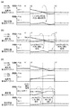
図8は、ノイズプロファイルPtを拡大補正する処理を示すタイミングチャート図である。図9は、ノイズプロファイルPtを縮小補正する処理を示すタイミングチャート図である。図8及び9におけるt1、t2、t3、It、Dt、Pt、Ut、Ntは、図5及び6におけるt1、t2、t3、It、Dt、Pt、Ut、Ntと同様であるため、説明を省略する。図11は、ノイズプロファイル補正処理に関する時定数の設定を示す図である。   FIG. 8 is a timing chart showing a process for enlarging and correcting the noise profile Pt. FIG. 9 is a timing chart showing a process for reducing and correcting the noise profile Pt. Since t1, t2, t3, It, Dt, Pt, Ut, and Nt in FIGS. 8 and 9 are the same as t1, t2, t3, It, Dt, Pt, Ut, and Nt in FIGS. Omitted. FIG. 11 is a diagram illustrating setting of a time constant related to the noise profile correction process.

図10は、制御部109によって行われるノイズプロファイル補正処理を示すフローチャートである。次に、図10を用いて、制御部109によって行われるノイズプロファイル補正処理について説明する。なお、プロファイル補正部256aがプロファイル作成部252aによって作成されたノイズプロファイルを補正する場合を一例に挙げて、以下、ノイズプロファイル補正処理について説明する。積分回路250aは、S307のおけるノイズプロファイル作成処理が行われた後、あらかじめ設定されたフレーム数の各周波数の振幅値の積分し、積分された振幅値をあらかじめ設定されたフレーム数で除算することで、各周波数毎の平均振幅値を算出する。あらかじめ設定されたフレーム数は、ユーザによって設定されても良い。あらかじめ設定されたフレーム数が「1」である場合、積分回路250aが出力する振幅スペクトルの値は、FFT207aから出力される値と等しくなる。積分回路250aは、各周波数毎の平均振幅値を振幅スペクトルDtとして出力する。   FIG. 10 is a flowchart showing a noise profile correction process performed by the control unit 109. Next, the noise profile correction process performed by the control unit 109 will be described with reference to FIG. The noise profile correction process will be described below by taking as an example a case where the profile correction unit 256a corrects the noise profile created by the profile creation unit 252a. The integration circuit 250a integrates the amplitude value of each frequency of a preset number of frames after the noise profile creation processing in S307 is performed, and divides the integrated amplitude value by the preset number of frames. Then, the average amplitude value for each frequency is calculated. The number of frames set in advance may be set by the user. When the preset number of frames is “1”, the value of the amplitude spectrum output from the integration circuit 250a is equal to the value output from the FFT 207a. The integrating circuit 250a outputs an average amplitude value for each frequency as an amplitude spectrum Dt.

制御部109は、積分回路250aから出力された振幅スペクトルDtが振幅スペクトルDt2以下であるか否かを判定する(S1001)。振幅スペクトルDtが振幅スペクトルDt2よりも大きいと判定された場合(S1001でNo)、制御部109は、プロファイル格納部253aに格納されているノイズプロファイルPtが第1の値Pmax以下であるか否かを判定する(S1002)。なお、第1の値Pmaxは、ノイズプロファイルPtの拡大補正を制限するための閾値である。さらに、第1の値Pmaxは、駆動ノイズを低減し過ぎることによる違和感を防止するために用いられる。   The control unit 109 determines whether or not the amplitude spectrum Dt output from the integration circuit 250a is equal to or less than the amplitude spectrum Dt2 (S1001). When it is determined that the amplitude spectrum Dt is larger than the amplitude spectrum Dt2 (No in S1001), the control unit 109 determines whether or not the noise profile Pt stored in the profile storage unit 253a is equal to or less than the first value Pmax. Is determined (S1002). The first value Pmax is a threshold value for limiting the expansion correction of the noise profile Pt. Furthermore, the first value Pmax is used to prevent a sense of incongruity due to excessive reduction of drive noise.

図8のように、タイミングt2からタイミングt3までの期間、駆動ノイズが大きくなることに伴い、振幅スペクトルDtが振幅スペクトルDt2よりも大きくなる。このため、プロファイル作成部252aで生成されたノイズプロファイルPtを使って減算処理を振幅スペクトル減算部211aに行わせるだけでは、振幅スペクトルDtと振幅スペクトルDt2との差分に対応する駆動ノイズは低減されなかった。そこで、ノイズプロファイルPtが第1の値Pmax以下であると判定された場合(S1002でYes)、制御部109は、時定数inc(fi)に応じてノイズプロファイルPtの拡大補正をプロファイル拡大部271aに行わせる(S1003)。ノイズプロファイルPtの拡大補正が行われた後、制御部109は、S1004の処理を行う。   As shown in FIG. 8, the amplitude spectrum Dt becomes larger than the amplitude spectrum Dt2 as the drive noise increases during the period from the timing t2 to the timing t3. For this reason, the drive noise corresponding to the difference between the amplitude spectrum Dt and the amplitude spectrum Dt2 is not reduced only by causing the amplitude spectrum subtraction unit 211a to perform the subtraction process using the noise profile Pt generated by the profile creation unit 252a. It was. Therefore, when it is determined that the noise profile Pt is equal to or less than the first value Pmax (Yes in S1002), the control unit 109 performs the expansion correction of the noise profile Pt according to the time constant inc (fi). (S1003). After the enlargement correction of the noise profile Pt is performed, the control unit 109 performs the process of S1004.

ノイズプロファイルPtが第1の値Pmax以下でないと判定された場合(S1002でNo)、駆動ノイズを低減し過ぎることを防止するために、制御部109は、ノイズプロファイルPtの拡大補正をプロファイル拡大部271aに行わせないようにする。ノイズプロファイルPtが第1の値Pmax以下でないと判定された場合(S1002でNo)、制御部109は、S1004の処理を行う。振幅スペクトルDtが振幅スペクトルDt2以下であると判定された場合(S1001でYes)、制御部109は、S1004の処理を行う。   When it is determined that the noise profile Pt is not equal to or less than the first value Pmax (No in S1002), the control unit 109 performs enlargement correction of the noise profile Pt to prevent the drive noise from being excessively reduced. 271a should not be performed. When it is determined that the noise profile Pt is not equal to or less than the first value Pmax (No in S1002), the control unit 109 performs the process of S1004. When it is determined that the amplitude spectrum Dt is equal to or smaller than the amplitude spectrum Dt2 (Yes in S1001), the control unit 109 performs the process of S1004.

制御部109は、振幅スペクトル減算部254aから出力された振幅スペクトルUtが第2の値Umin以上であるか否かを判定する(S1004)。なお、第2の値Uminは、ノイズプロファイルPtの縮小補正を制限する閾値である。第2の値Uminは、ノイズフロアレベルであり、音声入力部102に音声が入力されていない場合であっても、録音されてしまう最小のノイズの値である。ノイズプロファイルPtが第2の値Umin以上であると判定された場合(S1004でYes)、制御部109は、ノイズプロファイルPtの縮小補正をプロファイル縮小部272aに行わせないようにし、ノイズプロファイル補正処理を終了する。   The control unit 109 determines whether or not the amplitude spectrum Ut output from the amplitude spectrum subtraction unit 254a is greater than or equal to the second value Umin (S1004). The second value Umin is a threshold value that limits the reduction correction of the noise profile Pt. The second value Umin is a noise floor level, and is a minimum noise value that is recorded even when no sound is input to the sound input unit 102. When it is determined that the noise profile Pt is equal to or greater than the second value Umin (Yes in S1004), the control unit 109 prevents the profile reduction unit 272a from performing reduction correction of the noise profile Pt, and performs noise profile correction processing. Exit.

図9のように、タイミングt2からタイミングt3までの期間、駆動ノイズが小さくなることに伴い、振幅スペクトルUtが第2の値Utminよりも小さくなる。このため、プロファイル作成部252aで作成されたノイズプロファイルPtを使って減算処理を振幅スペクトル減算部254aに行わせるだけでは、振幅スペクトルUtと第2の値Utminとの差分に対応する音声が消されてしまう場合があった。そこで、ノイズプロファイルPtが第2の値Umin以上でないと判定された場合(S1004でNo)、制御部109は、時定数dec(fi)に応じてノイズプロファイルPtの縮小補正をプロファイル縮小部272aに行わせる(S1005)。ノイズプロファイルPtの縮小補正が行われた後、制御部109は、ノイズプロファイル補正処理を終了する。   As shown in FIG. 9, the amplitude spectrum Ut becomes smaller than the second value Utmin as the drive noise becomes smaller during the period from the timing t2 to the timing t3. For this reason, the sound corresponding to the difference between the amplitude spectrum Ut and the second value Utmin is erased only by causing the amplitude spectrum subtraction unit 254a to perform the subtraction process using the noise profile Pt created by the profile creation unit 252a. There was a case. Therefore, when it is determined that the noise profile Pt is not equal to or greater than the second value Umin (No in S1004), the control unit 109 causes the profile reduction unit 272a to perform reduction correction of the noise profile Pt according to the time constant dec (fi). (S1005). After the reduction correction of the noise profile Pt is performed, the control unit 109 ends the noise profile correction process.

なお、図10のノイズプロファイル補正処理について、プロファイル補正部256aがプロファイル作成部252aによって作成されたノイズプロファイルを補正する場合を一例に挙げて説明を行った。しかしながら、プロファイル補正部256bがプロファイル作成部252bによって作成されたノイズプロファイルを補正する場合も、図10のノイズプロファイル補正処理と同様にノイズプロファイルの補正を行う。   Note that the noise profile correction processing of FIG. 10 has been described by taking as an example the case where the profile correction unit 256a corrects the noise profile created by the profile creation unit 252a. However, when the profile correction unit 256b corrects the noise profile created by the profile creation unit 252b, the noise profile is corrected similarly to the noise profile correction process of FIG.

次に、図11を用いて、プロファイル拡大部271aによるノイズプロファイルPtの拡大補正の時定数inc(fi)及びプロファイル縮小部272aによるノイズプロファイルPtの縮小補正の時定数dec(fi)を設定する方法について説明する。   Next, referring to FIG. 11, a method of setting the time constant inc (fi) for the expansion correction of the noise profile Pt by the profile expansion unit 271a and the time constant dec (fi) for the reduction correction of the noise profile Pt by the profile reduction unit 272a. Will be described.

図11(A)は、駆動ノイズの周波数毎の特性を示す図である。図11(B)は、ノイズプロファイルPtを拡大補正する場合の周波数に応じた時定数inc(fi)の設定を示す図である。図11(C)は、ノイズプロファイルPtを縮小補正する場合の周波数に応じた時定数dec(fi)の設定を表す図である。   FIG. 11A is a diagram illustrating characteristics of driving noise for each frequency. FIG. 11B is a diagram showing the setting of the time constant inc (fi) corresponding to the frequency when the noise profile Pt is enlarged and corrected. FIG. 11C is a diagram illustrating the setting of the time constant dec (fi) according to the frequency when the noise profile Pt is reduced and corrected.

図11(A)において、1101は、撮像装置100によってズーム動作が行われている場合における振幅スペクトルを512ポイントの振幅スペクトルで示したものである。1102は、撮像装置100によってズーム動作が行われている場合における駆動ノイズの振幅スペクトルの変化を示したものである。1102が示すように、周波数帯が高域になるほど、撮像装置100によってズーム動作が行われている場合における駆動ノイズの変化が大きくなる。   In FIG. 11A, reference numeral 1101 denotes an amplitude spectrum when the zoom operation is performed by the imaging apparatus 100 as an amplitude spectrum of 512 points. Reference numeral 1102 denotes a change in the amplitude spectrum of the drive noise when the zoom operation is performed by the imaging apparatus 100. As 1102 indicates, the higher the frequency band, the greater the change in drive noise when the zoom operation is performed by the imaging apparatus 100.

これにより、図11(B)のように、プロファイル拡大部271aによるノイズプロファイルPtの拡大補正が行われる場合、周波数帯域が高くなるほど、時定数inc(fi)は、小さくなるように設定される。これは、駆動ノイズの変化に対して、ノイズプロファイルPtの拡大補正を早く追従させることによって、駆動ノイズが低減されず残ってしまうような事態を防止するためである。   Thus, as shown in FIG. 11B, when the noise profile Pt is enlarged and corrected by the profile enlargement unit 271a, the time constant inc (fi) is set to be smaller as the frequency band is higher. This is to prevent the drive noise from being left unreduced by causing the enlargement correction of the noise profile Pt to follow the change in the drive noise quickly.

また、図11(C)のように、プロファイル縮小部272aによるノイズプロファイルPtの縮小補正が行われる場合、周波数帯域が高くなるほど、時定数dec(fi)は、大きくなるように設定される。これは、駆動ノイズの変化に対して、ノイズプロファイルPtの縮小補正を遅く追従させることによって、駆動ノイズが低減されず残ってしまうような事態を防止するためである。   In addition, as shown in FIG. 11C, when the noise profile Pt is reduced and corrected by the profile reduction unit 272a, the time constant dec (fi) is set to increase as the frequency band increases. This is to prevent the drive noise from remaining unreduced by causing the reduction correction of the noise profile Pt to follow the change of the drive noise slowly.

本実施形態において、ノイズプロファイルPtを縮小補正する際の時定数dec(fi)は、ノイズプロファイルPtを拡大補正する際の時定数inc(fi)よりも大きくする。   In the present embodiment, the time constant dec (fi) for correcting the noise profile Pt to be reduced is set larger than the time constant inc (fi) for correcting the noise profile Pt to be enlarged.

IFFT214aによって時系列の音声信号に戻された後に、ノイズ印加部215aは、IFFT214aから供給された音声信号にノイズ信号を印加する。ノイズ印加部215aは、ノイズ低減部200aによる駆動ノイズの低減し過ぎによる違和感を防止するために、ノイズ信号を印加する。ノイズ印加部215aによって印加されるノイズ信号は、ノイズフロアレベルの信号であるものとする。これにより、振幅スペクトル減算部254aによる減算処理は、駆動ノイズの低減が重視される。   After being returned to the time-series audio signal by the IFFT 214a, the noise applying unit 215a applies the noise signal to the audio signal supplied from the IFFT 214a. The noise application unit 215a applies a noise signal in order to prevent a sense of incongruity due to excessive reduction of drive noise by the noise reduction unit 200a. It is assumed that the noise signal applied by the noise applying unit 215a is a noise floor level signal. As a result, in the subtraction processing by the amplitude spectrum subtraction unit 254a, reduction of driving noise is emphasized.

図12は、外部音源1201と音声入力部102との関係の一例を示す図である。図12のように、外部音源1201と撮像装置100との距離が十分に離れている場合、外部音源1201とRチャネル音声入力部102aとの距離と、外部音源1201とLチャネル音声入力部102bとの距離とは、ほぼ同じである。このため、マイク205aによって取得される環境音と、マイク205bによって取得される環境音との差は小さい。   FIG. 12 is a diagram illustrating an example of the relationship between the external sound source 1201 and the audio input unit 102. As shown in FIG. 12, when the distance between the external sound source 1201 and the imaging device 100 is sufficiently large, the distance between the external sound source 1201 and the R channel sound input unit 102a, the external sound source 1201 and the L channel sound input unit 102b, Is substantially the same. For this reason, the difference between the environmental sound acquired by the microphone 205a and the environmental sound acquired by the microphone 205b is small.

しがしながら、光学レンズ201とRチャネル音声入力部102aとの距離と、光学レンズ201とLチャネル音声入力部102bとの距離との差による駆動ノイズの影響は異なる。そのため、Rチャネル音声入力部102aに対する駆動ノイズの影響と、Lチャネル音声入力部102bに対する駆動ノイズの影響とをそれぞれ考慮する必要がある。   However, the influence of the drive noise due to the difference between the distance between the optical lens 201 and the R channel audio input unit 102a and the distance between the optical lens 201 and the L channel audio input unit 102b is different. Therefore, it is necessary to consider the influence of driving noise on the R channel audio input unit 102a and the influence of driving noise on the L channel audio input unit 102b, respectively.

次の式に示されるように、Rチャネル音声入力部102aに対する駆動ノイズの影響とLチャネル音声入力部102bに対する駆動ノイズの影響との差は、大きくなる。次の式の「DtL」は、ノイズ低減処理が行われる前のL(Left)のチャネルの振幅値であり、「DtR」は、ノイズ低減処理が行われる前のR(Right)のチャネルの振幅値である。さらに、次の式の「βt」は、左右相関振幅スペクトルである。
βt=|DtL−DtR|/(DtL+DtR)
As shown in the following equation, the difference between the influence of driving noise on the R channel audio input unit 102a and the influence of driving noise on the L channel audio input unit 102b becomes large. In the following equation, “DtL” is the amplitude value of the L (Left) channel before the noise reduction processing is performed, and “DtR” is the amplitude of the R (Right) channel before the noise reduction processing is performed. Value. Further, “βt” in the following expression is a left-right correlation amplitude spectrum.
βt = | DtL−DtR | / (DtL + DtR)

環境音は、音量が大きいほど、LchとRchとで差分は大きくなる。しかし、図12のような場合、外部音源1201とRチャネル音声入力部102aとの距離と、外部音源1201とLチャネル音声入力部102bとの距離とは、ほぼ同じなので、左右相関振幅スペクトルβtは小さくなる。駆動ノイズについては、光学レンズ201とRチャネル音声入力部102aとの距離と、光学レンズ201とLチャネル音声入力部102bとの距離との差により、左右相関振幅スペクトルβtは大きくなる。左右相関振幅スペクトルβtにより、駆動ノイズが環境音に対して支配的か否かを判定することができる。   The difference between Lch and Rch increases as the volume of the environmental sound increases. However, in the case as shown in FIG. 12, the distance between the external sound source 1201 and the R channel sound input unit 102a and the distance between the external sound source 1201 and the L channel sound input unit 102b are substantially the same. Get smaller. Regarding the drive noise, the left-right correlation amplitude spectrum βt increases due to the difference between the distance between the optical lens 201 and the R channel audio input unit 102a and the distance between the optical lens 201 and the L channel audio input unit 102b. Whether the driving noise is dominant with respect to the environmental sound can be determined from the left-right correlation amplitude spectrum βt.

次に、図13及び図14を用いて、Rchに対する駆動ノイズの影響と、Lchに対する駆動ノイズの影響とを考慮したノイズプロファイル補正処理について説明を行う。   Next, a noise profile correction process that takes into account the influence of drive noise on Rch and the influence of drive noise on Lch will be described with reference to FIGS. 13 and 14.

図13は、Rch及びLchに対してノイズプロファイルを補正する処理を示すタイミングチャート図である。図13におけるt1、t2、t3は、図5及び6におけるt1、t2、t3と同様であるため、説明を省略する。
図13において、FFT207aによって高速フーリエ変換された所定の周波数fiの振幅スペクトルを「ItR」とし、FFT207bによって高速フーリエ変換された所定の周波数fiの振幅スペクトルを「ItL」とする。振幅スペクトルItRは、点線で示され、振幅スペクトルItLは、実線で示される。さらに、図13において、積分回路250aによって積分された所定の周波数fiの振幅を示す振幅スペクトルを「DtR」とし、積分回路250bによって積分された所定の周波数fiの振幅を示す振幅スペクトルを「DtL」とする。振幅スペクトルDtRは、点線で示され、振幅スペクトルDtLは、実線で示される。図13において、プロファイル作成部252aによって作成された所定の周波数fiに対応するノイズプロファイルを「PtR」とし、プロファイル作成部252bによって作成された所定の周波数fiに対応するノイズプロファイルを「PtL」とする。ノイズプロファイルPtRは、点線で示され、ノイズプロファイルPtLは、実線で示される。タイミングt2において、プロファイル作成部252aによってノイズプロファイルPtRが作成され、プロファイル作成部252bによってノイズプロファイルPtLが作成される。
FIG. 13 is a timing chart showing a process for correcting a noise profile for Rch and Lch. Since t1, t2, and t3 in FIG. 13 are the same as t1, t2, and t3 in FIGS. 5 and 6, description thereof is omitted.
In FIG. 13, the amplitude spectrum of the predetermined frequency fi that is fast Fourier transformed by the FFT 207a is “ItR”, and the amplitude spectrum of the predetermined frequency fi that is fast Fourier transformed by the FFT 207b is “ItL”. The amplitude spectrum ItR is indicated by a dotted line, and the amplitude spectrum ItL is indicated by a solid line. Further, in FIG. 13, the amplitude spectrum indicating the amplitude of the predetermined frequency fi integrated by the integration circuit 250a is “DtR”, and the amplitude spectrum indicating the amplitude of the predetermined frequency fi integrated by the integration circuit 250b is “DtL”. And The amplitude spectrum DtR is indicated by a dotted line, and the amplitude spectrum DtL is indicated by a solid line. In FIG. 13, the noise profile corresponding to the predetermined frequency fi created by the profile creation unit 252a is “PtR”, and the noise profile corresponding to the predetermined frequency fi created by the profile creation unit 252b is “PtL”. . The noise profile PtR is indicated by a dotted line, and the noise profile PtL is indicated by a solid line. At timing t2, a noise profile PtR is created by the profile creation unit 252a, and a noise profile PtL is created by the profile creation unit 252b.

図13において、振幅スペクトル減算部254aから出力される所定の周波数fiの振幅スペクトルを「UtR」とし、振幅スペクトル減算部254bから出力される所定の周波数fiの振幅スペクトルを「UtL」とする。振幅スペクトルUtRは、点線で示され、振幅スペクトルUtLは、実線で示される。図13において、ノイズ印加部215aによってノイズ信号が印加された後の所定の周波数fiの時系列のデジタル音声信号を「NtR」とする。図13において、ノイズ印加部215bによってノイズ信号が印加された後の所定の周波数fiの時系列のデジタル音声信号を「NtL」とする。振幅スペクトルNtRは、点線で示され、振幅スペクトルNtLは、実線で示される。図13において、振幅スペクトルItLと振幅スペクトルItRとの差分の絶対値である|ItL−ItR|は、実線で示される。図13において、振幅スペクトルUtLと振幅スペクトルUtRとの差分の絶対値である|UtL−UtR|は、点線で示される。   In FIG. 13, the amplitude spectrum of the predetermined frequency fi output from the amplitude spectrum subtraction unit 254a is “UtR”, and the amplitude spectrum of the predetermined frequency fi output from the amplitude spectrum subtraction unit 254b is “UtL”. The amplitude spectrum UtR is indicated by a dotted line, and the amplitude spectrum UtL is indicated by a solid line. In FIG. 13, a time-series digital audio signal having a predetermined frequency fi after the noise signal is applied by the noise applying unit 215 a is referred to as “NtR”. In FIG. 13, a time-series digital audio signal having a predetermined frequency fi after the noise signal is applied by the noise applying unit 215 b is “NtL”. The amplitude spectrum NtR is indicated by a dotted line, and the amplitude spectrum NtL is indicated by a solid line. In FIG. 13, | ItL−ItR |, which is the absolute value of the difference between the amplitude spectrum ItL and the amplitude spectrum ItR, is indicated by a solid line. In FIG. 13, | UtL−UtR |, which is the absolute value of the difference between the amplitude spectrum UtL and the amplitude spectrum UtR, is indicated by a dotted line.

図13に示すように、|UtL−UtR|が|ItL−ItR|を上回る場合がある。これは、振幅スペクトルUtL及び振幅スペクトルUtRのいずれか一つが減算処理により駆動ノイズが低減され過ぎていることを示す。これは、ノイズプロファイルPtL及びノイズプロファイルPtRのいずれか一つが大き過ぎることが原因となって起こることである。   As illustrated in FIG. 13, | UtL−UtR | may exceed | ItL−ItR |. This indicates that the drive noise of one of the amplitude spectrum UtL and the amplitude spectrum UtR is excessively reduced by the subtraction process. This is because one of the noise profile PtL and the noise profile PtR is too large.

図14は、Rch及びLchに対するノイズプロファイル補正処理の一例を示すフローチャートである。次に、図14を用いて、制御部109によって行われるRch及びLchに対するノイズプロファイル補正処理について説明する。なお、ノイズプロファイルPtRに対して図10のノイズプロファイル補正処理が行われ、ノイズプロファイルPtLに対して図10のノイズプロファイル補正処理が行われた後、図14のRch及びLchに対するノイズプロファイル補正処理が行われる。   FIG. 14 is a flowchart illustrating an example of noise profile correction processing for Rch and Lch. Next, the noise profile correction processing for Rch and Lch performed by the control unit 109 will be described with reference to FIG. 10 is performed on the noise profile PtR, and after the noise profile correction process of FIG. 10 is performed on the noise profile PtL, the noise profile correction process on Rch and Lch in FIG. 14 is performed. Done.

この後、制御部109は、振幅スペクトルItL、振幅スペクトルItR、振幅スペクトルUtL及び振幅スペクトルUtRを検出し、以下の条件が成立しているか否かを判定する(S1401)。
条件:|ItL−ItR|≦|UtL−UtR|
条件|ItL−ItR|≦|UtL−UtR|が成立していると判定された場合(S1401でYes)、制御部109は、振幅スペクトルUtLが振幅スペクトルUtR以上であるか否かを判定する(S1402)。振幅スペクトルUtLが振幅スペクトルUtR以上である場合(S1402でYes)、制御部109は、時定数inc_L(fi)に応じてノイズプロファイルPtLの拡大補正をプロファイル拡大部271bに行わせる(S1403)。時定数inc_L(fi)は、プロファイル拡大部271bに対応する時定数である。その後、制御部109は、時定数dec_R(fi)に応じてノイズプロファイルPtRの縮小補正をプロファイル縮小部272aに行わせる(S1404)。時定数dec_R(fi)は、プロファイル縮小部272aに対応する時定数である。S1404の処理が行われた後、Rch及びLchに対するノイズプロファイル補正処理は終了する。時定数dec_R(fi)は、時定数inc_L(fi)よりも大きくなる。
Thereafter, the control unit 109 detects the amplitude spectrum ItL, the amplitude spectrum ItR, the amplitude spectrum UtL, and the amplitude spectrum UtR, and determines whether or not the following conditions are satisfied (S1401).
Condition: | ItL-ItR | ≦ | UtL-UtR |
When it is determined that the condition | ItL−ItR | ≦ | UtL−UtR | is satisfied (Yes in S1401), the control unit 109 determines whether or not the amplitude spectrum UtL is greater than or equal to the amplitude spectrum UtR ( S1402). When the amplitude spectrum UtL is equal to or larger than the amplitude spectrum UtR (Yes in S1402), the control unit 109 causes the profile enlargement unit 271b to perform the enlargement correction of the noise profile PtL according to the time constant inc_L (fi) (S1403). The time constant inc_L (fi) is a time constant corresponding to the profile enlarging unit 271b. Thereafter, the control unit 109 causes the profile reduction unit 272a to perform reduction correction of the noise profile PtR according to the time constant dec_R (fi) (S1404). The time constant dec_R (fi) is a time constant corresponding to the profile reduction unit 272a. After the processing of S1404 is performed, the noise profile correction processing for Rch and Lch ends. The time constant dec_R (fi) is larger than the time constant inc_L (fi).

振幅スペクトルUtLが振幅スペクトルUtRよりも小さいと判定された場合(S1402でNo)、制御部109は、時定数inc_R(fi)に応じてノイズプロファイルPtRの拡大補正をプロファイル拡大部271aに行わせる(S1405)。時定数inc_R(fi)は、プロファイル拡大部271aに対応する時定数である。その後、制御部109は、時定数dec_L(fi)に応じてノイズプロファイルPtLの縮小補正をプロファイル縮小部272bに行わせる(S1406)。時定数dec_L(fi)は、プロファイル縮小部272bに対応する時定数である。S1406の処理が行われた後、Rch及びLchに対するノイズプロファイル補正処理は終了する。時定数dec_L(fi)は、時定数inc_R(fi)よりも大きくなる。   When it is determined that the amplitude spectrum UtL is smaller than the amplitude spectrum UtR (No in S1402), the control unit 109 causes the profile expansion unit 271a to perform expansion correction of the noise profile PtR according to the time constant inc_R (fi) ( S1405). The time constant inc_R (fi) is a time constant corresponding to the profile enlarging unit 271a. Thereafter, the control unit 109 causes the profile reduction unit 272b to perform reduction correction of the noise profile PtL according to the time constant dec_L (fi) (S1406). The time constant dec_L (fi) is a time constant corresponding to the profile reduction unit 272b. After the processing of S1406 is performed, the noise profile correction processing for Rch and Lch ends. The time constant dec_L (fi) is larger than the time constant inc_R (fi).

条件|ItL−ItR|≦|UtL−UtR|が成立していない場合、|ItL−ItR|>|UtL−UtR|となる。条件|ItL−ItR|≦|UtL−UtR|が成立していないと判定された場合(S1401でNo)、Rch及びLchに対するノイズプロファイル補正処理は終了する。   When the condition | ItL−ItR | ≦ | UtL−UtR | is not satisfied, | ItL−ItR |> | UtL−UtR | If it is determined that the condition | ItL−ItR | ≦ | UtL−UtR | is not satisfied (No in S1401), the noise profile correction processing for Rch and Lch ends.

このように、制御部109は、環境音や駆動ノイズの変化に伴い、ノイズプロファイルPtRに対して補正を行い、ノイズプロファイルPtLに対して補正を行うようにした。これにより、撮像装置100は、Rchの音声に対するノイズ低減処理と、Lchの音声に対するノイズ低減処理とが適切に行われるようにすることができる。したがって、撮像装置100は、駆動ノイズの消し残しや駆動ノイズの低減し過ぎによって環境音に違和感が生じるような事態を防止することができる。   As described above, the control unit 109 corrects the noise profile PtR and corrects the noise profile PtL in accordance with changes in environmental sound and driving noise. Accordingly, the imaging apparatus 100 can appropriately perform the noise reduction process for the Rch sound and the noise reduction process for the Lch sound. Therefore, the imaging apparatus 100 can prevent a situation in which the environmental sound is uncomfortable due to the drive noise remaining unerased or the drive noise being excessively reduced.

[ノイズ低減処理(S308)]
S308において、制御部109によって実行されるノイズ低減処理について図15、16及び17を用いて説明を行う。
[Noise reduction processing (S308)]
The noise reduction process executed by the control unit 109 in S308 will be described with reference to FIGS.

図15は、Rch及びLchに対するノイズ低減処理を示すタイミングチャート図である。図15におけるt1、t2、t3は、図5及び6におけるt1、t2、t3と同様であるため、説明を省略する。図15におけるItR、ItL、DtR、DtL、PtR、PtL、UtR、UtL、NtR及びNtLは、図13におけるItR、ItL、DtR、DtL、PtR、PtL、UtR、UtL、NtR及びNtLと同様であるため、説明を省略する。   FIG. 15 is a timing chart showing noise reduction processing for Rch and Lch. Since t1, t2, and t3 in FIG. 15 are the same as t1, t2, and t3 in FIGS. 5 and 6, description thereof is omitted. In FIG. 15, ItR, ItL, DtR, DtL, PtR, PtL, UtR, UtL, NtR and NtL are the same as ItR, ItL, DtR, DtL, PtR, PtL, UtR, UtL, NtR and NtL in FIG. Therefore, the description is omitted.

撮像装置100によってズーム動作が行われている間に環境音や駆動ノイズが急激に変化した場合、ノイズプロファイルPtR及びノイズプロファイルPtLを用いて駆動ノイズを低減したとしても、駆動ノイズの消し残りや環境音に違和感が生じる場合がある。これを防止するために、制御部109は、左右相関振幅スペクトルβtに応じて、ノイズ低減処理を行う。   If the environmental sound or driving noise changes abruptly while the zoom operation is being performed by the imaging apparatus 100, even if the driving noise is reduced using the noise profile PtR and the noise profile PtL, the remaining noise of driving noise and the environment The sound may be uncomfortable. In order to prevent this, the control unit 109 performs noise reduction processing according to the left-right correlation amplitude spectrum βt.

図16は、ノイズ低減処理の一例を示すフローチャートである。図17は、係数αと環境音との関係を示す図である。図17の横軸は、環境音のレベルを示し、図17の縦軸は、係数αの値を示している。図17において、環境音のレベルに係数αが対応づけられている。図17における実線1701が、環境音のレベルに対応した係数αの値を示している。破線1702は、駆動ノイズのレベルであり、破線1703は、駆動ノイズが環境音によってかき消されるレベルである。係数αは、環境音レベルの大きくなるほど、小さくなるものとする。環境音のレベルが破線1702のレベルである場合、係数αは0.125となる。   FIG. 16 is a flowchart illustrating an example of noise reduction processing. FIG. 17 is a diagram illustrating the relationship between the coefficient α and the environmental sound. The horizontal axis in FIG. 17 indicates the environmental sound level, and the vertical axis in FIG. 17 indicates the value of the coefficient α. In FIG. 17, the coefficient α is associated with the environmental sound level. A solid line 1701 in FIG. 17 indicates the value of the coefficient α corresponding to the environmental sound level. A broken line 1702 is a drive noise level, and a broken line 1703 is a level at which the drive noise is erased by the environmental sound. The coefficient α decreases as the environmental sound level increases. When the environmental sound level is the level indicated by the broken line 1702, the coefficient α is 0.125.

次に、図16(a)及び図17を用いて、制御部109によって行われるノイズ低減処理について説明を行う。なお、図16(a)のノイズ低減処理について、振幅スペクトル減算部254aが減算処理を行う場合を一例に挙げて説明を行う。   Next, the noise reduction process performed by the control unit 109 will be described with reference to FIGS. Note that the noise reduction processing in FIG. 16A will be described using an example in which the amplitude spectrum subtraction unit 254a performs subtraction processing.

タイミングt1において、制御部109は、メモリ251aに保存された振幅スペクトルDt1に応じて、係数αを決定する(S1601)。係数αは、ノイズプロファイルに乗算する係数である。S1601において、制御部109は、振幅スペクトルDt1に対応する図17のおける環境音のレベルを検出し、検出された環境音のレベルに対応する係数αの値を決定する。   At timing t1, the control unit 109 determines the coefficient α according to the amplitude spectrum Dt1 stored in the memory 251a (S1601). The coefficient α is a coefficient by which the noise profile is multiplied. In S1601, the control unit 109 detects the level of the environmental sound in FIG. 17 corresponding to the amplitude spectrum Dt1, and determines the value of the coefficient α corresponding to the detected level of the environmental sound.

次に、制御部109は、上述のように左右相関振幅スペクトルβtを算出する(S1602)。その後、制御部109は、左右相関振幅スペクトルβtが第3の値βth以下であるか否かを判定する(S1603)。なお、第3の値βthは、環境音がないときにおいて算出された左右相関振幅スペクトルβtの値に応じて設定される。環境音のレベルが大きいほど、左右相関振幅スペクトルβtは0に近くなる。また、環境音に対して駆動ノイズが支配的である場合、左右相関振幅スペクトルβtは、0.2以上になる。   Next, the control unit 109 calculates the left-right correlation amplitude spectrum βt as described above (S1602). Thereafter, the control unit 109 determines whether or not the left-right correlation amplitude spectrum βt is equal to or smaller than the third value βth (S1603). Note that the third value βth is set according to the value of the left-right correlation amplitude spectrum βt calculated when there is no environmental sound. The greater the level of environmental sound, the closer the left-right correlation amplitude spectrum βt is to zero. When the driving noise is dominant with respect to the environmental sound, the left-right correlation amplitude spectrum βt is 0.2 or more.

左右相関振幅スペクトルβtが第3の値βth以下であると判定された場合(S1603でYes)、制御部109は、S1604の処理を行う。S1604において、制御部109は、ノイズプロファイルPtRとS1601において決定された係数αとを乗算し、これを振幅スペクトルItRから減算するように振幅スペクトル減算部254aを制御する。S1604において、振幅スペクトル減算部254aによって減算処理が行われた場合、振幅スペクトル減算部254aから出力される振幅スペクトルUtRは、次式のようになる。
UtR=ItR−α・PtR
When it is determined that the left-right correlation amplitude spectrum βt is equal to or smaller than the third value βth (Yes in S1603), the control unit 109 performs the process of S1604. In S1604, the control unit 109 multiplies the noise profile PtR by the coefficient α determined in S1601, and controls the amplitude spectrum subtraction unit 254a to subtract this from the amplitude spectrum ItR. In S1604, when the subtraction process is performed by the amplitude spectrum subtraction unit 254a, the amplitude spectrum UtR output from the amplitude spectrum subtraction unit 254a is expressed by the following equation.
UtR = ItR−α · PtR

左右相関振幅スペクトルβtが第3の値βthよりも大きいと判定された場合(S1603でNo)、制御部109は、S1605の処理を行う。S1605において、制御部109は、第1の値PmaxとS1601において決定された係数αとを乗算し、これを振幅スペクトルItRから減算するように振幅スペクトル減算部254aを制御する。S1605において、振幅スペクトル減算部254aによって減算処理が行われた場合、振幅スペクトル減算部254aから出力される振幅スペクトルUtRは、次式のようになる。
UtR=ItR−α・Pmax
When it is determined that the left-right correlation amplitude spectrum βt is larger than the third value βth (No in S1603), the control unit 109 performs the process of S1605. In step S1605, the control unit 109 multiplies the first value Pmax by the coefficient α determined in step S1601, and controls the amplitude spectrum subtraction unit 254a to subtract this from the amplitude spectrum ItR. In S1605, when the subtraction process is performed by the amplitude spectrum subtraction unit 254a, the amplitude spectrum UtR output from the amplitude spectrum subtraction unit 254a is expressed by the following equation.
UtR = ItR−α · Pmax

左右相関振幅スペクトルβtが第3の値βth以下でないと判定された場合(S1603でNo)、制御部109は、ノイズプロファイルPtRを用いないようにする。なお、図16(a)のノイズ低減処理について、振幅スペクトル減算部254aが減算処理を行う場合を一例に挙げて説明を行った。しかしながら、振幅スペクトル減算部254bが減算処理を行う場合も、図16(a)のノイズ低減処理と同様に駆動ノイズの低減を行う。   When it is determined that the left-right correlation amplitude spectrum βt is not equal to or smaller than the third value βth (No in S1603), the control unit 109 does not use the noise profile PtR. Note that the noise reduction processing in FIG. 16A has been described by taking as an example the case where the amplitude spectrum subtraction unit 254a performs the subtraction processing. However, also when the amplitude spectrum subtraction unit 254b performs the subtraction process, the drive noise is reduced in the same manner as the noise reduction process of FIG.

次に、図16(b)及び図17を用いて、制御部109によって行われるノイズ低減処理について説明を行う。なお、図16(b)のノイズ低減処理について、振幅スペクトル減算部254aが減算処理を行う場合を一例に挙げて説明を行う。   Next, the noise reduction process performed by the control unit 109 will be described with reference to FIGS. Note that the noise reduction processing in FIG. 16B will be described by taking the case where the amplitude spectrum subtraction unit 254a performs the subtraction processing as an example.

図16(b)におけるS1602、S1603及びS1604は、図16(b)におけるS1602、S1603及びS1604と同一の処理であるので、説明を省略する。制御部109は、前フレームの減算処理後の振幅スペクトルUt−1に応じて、係数αを決定する(S1606)。S1606において、制御部109は、振幅スペクトルUt−1に対応する図17のおける環境音のレベルを検出し、検出された環境音のレベルに対応する係数αの値を決定する。振幅スペクトル減算部254aが減算処理を行う場合、S1606において、制御部109は、振幅スペクトル減算部254aによって行われた前フレームの減算処理後の振幅スペクトルUt−1Rに応じて、係数αを決定する。その後、制御部109は、S1602及びS1603の処理が行われる。左右相関振幅スペクトルβtが第3の値βth以下であると判定された場合(S1603でYes)、制御部109は、S1604の処理を行う。左右相関振幅スペクトルβtが第3の値βth以下でないと判定された場合(S1603でNo)、制御部109は、S1607の処理を行う。   Since S1602, S1603, and S1604 in FIG. 16B are the same processes as S1602, S1603, and S1604 in FIG. The control unit 109 determines the coefficient α according to the amplitude spectrum Ut−1 after the subtraction process of the previous frame (S1606). In S1606, the control unit 109 detects the level of the environmental sound in FIG. 17 corresponding to the amplitude spectrum Ut-1, and determines the value of the coefficient α corresponding to the detected level of the environmental sound. When the amplitude spectrum subtraction unit 254a performs the subtraction process, in step S1606, the control unit 109 determines the coefficient α according to the amplitude spectrum Ut-1R after the subtraction process for the previous frame performed by the amplitude spectrum subtraction unit 254a. . Thereafter, the control unit 109 performs the processes of S1602 and S1603. When it is determined that the left-right correlation amplitude spectrum βt is equal to or smaller than the third value βth (Yes in S1603), the control unit 109 performs the process of S1604. When it is determined that the left-right correlation amplitude spectrum βt is not equal to or smaller than the third value βth (No in S1603), the control unit 109 performs the process of S1607.

S1607において、制御部109は、第2の値UminとS1606において決定された係数αとを乗算し、これを振幅スペクトルItRから減算するように振幅スペクトル減算部254aを制御する。S1607において、振幅スペクトル減算部254aによって減算処理が行われた場合、振幅スペクトル減算部254aから出力される振幅スペクトルUtRは、次式のようになる。
UtR=ItR−α・Umin
In S1607, the control unit 109 multiplies the second value Umin by the coefficient α determined in S1606, and controls the amplitude spectrum subtraction unit 254a to subtract this from the amplitude spectrum ItR. In S1607, when the subtraction process is performed by the amplitude spectrum subtraction unit 254a, the amplitude spectrum UtR output from the amplitude spectrum subtraction unit 254a is expressed by the following equation.
UtR = ItR−α · Umin

左右相関振幅スペクトルβtが第3の値βth以下でないと判定された場合(S1603でNo)、制御部109は、ノイズプロファイルPtRを用いないようにする。なお、図16(b)のノイズ低減処理について、振幅スペクトル減算部254aが減算処理を行う場合を一例に挙げて説明を行った。しかしながら、振幅スペクトル減算部254bが減算処理を行う場合も、図16(b)のノイズ低減処理と同様に駆動ノイズの低減を行う。   When it is determined that the left-right correlation amplitude spectrum βt is not equal to or smaller than the third value βth (No in S1603), the control unit 109 does not use the noise profile PtR. Note that the noise reduction process in FIG. 16B has been described by taking as an example the case where the amplitude spectrum subtraction unit 254a performs the subtraction process. However, even when the amplitude spectrum subtraction unit 254b performs the subtraction process, the drive noise is reduced in the same manner as the noise reduction process of FIG.

ノイズ低減処理について、図16(a)及び図16(b)について説明したが、図16(a)及び図16(b)のいずれか一つのノイズ低減処理が制御部109によって行われればよいものとする。   Although the noise reduction processing has been described with reference to FIGS. 16A and 16B, any one of the noise reduction processing in FIGS. 16A and 16B may be performed by the control unit 109. And

このように、制御部109は、左右相関振幅スペクトルβtに応じて、ノイズを低減するための処理を変更するようにした。これにより、撮像装置100は、駆動ノイズが環境音に対して支配的か否かに応じて、適切に駆動ノイズを低減することができる。   As described above, the control unit 109 changes the process for reducing noise according to the left-right correlation amplitude spectrum βt. Thereby, the imaging device 100 can appropriately reduce the drive noise depending on whether the drive noise is dominant with respect to the environmental sound.

[後処理(S310)]
S310において、制御部109によって実行される後処理について図18及び19を用いて説明を行う。
[Post-processing (S310)]
In S310, post-processing executed by the control unit 109 will be described with reference to FIGS.

図18は、後処理を示すタイミングチャート図である。図18におけるt1、t2、t3は、図5及び6におけるt1、t2、t3と同様であるため、説明を省略する。図18におけるUtR、UtLは、図13におけるUtR、UtLと同様であるため、説明を省略する。図18における振幅スペクトルQtは、後処理が行われた後に出力される振幅スペクトルである。   FIG. 18 is a timing chart showing post-processing. Since t1, t2, and t3 in FIG. 18 are the same as t1, t2, and t3 in FIGS. 5 and 6, description thereof is omitted. UtR and UtL in FIG. 18 are the same as UtR and UtL in FIG. The amplitude spectrum Qt in FIG. 18 is an amplitude spectrum that is output after post-processing.

次に、図19(a)及び図18(a)を用いて、制御部109によって行われる後処理について説明を行う。振幅スペクトル減算部254aから振幅スペクトルUtRが出力され、振幅スペクトル減算部254bから振幅スペクトルUtLが出力された場合、制御部109は、振幅スペクトルUtLが振幅スペクトルUtR以下であるか否かを判定する(S1901)。   Next, post-processing performed by the control unit 109 will be described with reference to FIGS. 19A and 18A. When the amplitude spectrum UtR is output from the amplitude spectrum subtraction unit 254a and the amplitude spectrum UtL is output from the amplitude spectrum subtraction unit 254b, the control unit 109 determines whether or not the amplitude spectrum UtL is equal to or less than the amplitude spectrum UtR ( S1901).

振幅スペクトルUtLが振幅スペクトルUtR以下であると判定された場合(S1901でYes)、制御部109は、振幅スペクトルUtLを振幅スペクトルQtとしてIFFT214bに出力するように後補正部255bを制御する。その後、制御部109は、振幅スペクトルUtRをIFFT214aに出力することなく、振幅スペクトルUtLを振幅スペクトルQtとしてIFFT214aに出力するように後補正部255aを制御する(S1902)。S1902の処理が行われた後、制御部109は、後処理を終了する。   When it is determined that the amplitude spectrum UtL is equal to or smaller than the amplitude spectrum UtR (Yes in S1901), the control unit 109 controls the post-correction unit 255b to output the amplitude spectrum UtL as the amplitude spectrum Qt to the IFFT 214b. Thereafter, the control unit 109 controls the post-correction unit 255a to output the amplitude spectrum UtL as the amplitude spectrum Qt to the IFFT 214a without outputting the amplitude spectrum UtR to the IFFT 214a (S1902). After the process of S1902 is performed, the control unit 109 ends the post-process.

振幅スペクトルUtLが振幅スペクトルUtRよりも大きいと判定された場合(S1901でNo)、制御部109は、振幅スペクトルUtRを振幅スペクトルQtとしてIFFT214aに出力するように後補正部255aを制御する。その後、制御部109は、振幅スペクトルUtLをIFFT214bに出力することなく、振幅スペクトルUtRを振幅スペクトルQtとしてIFFT214bに出力するように後処理部255bを制御する(S1903)。S1903の処理が行われた後、制御部109は、後処理を終了する。   When it is determined that the amplitude spectrum UtL is larger than the amplitude spectrum UtR (No in S1901), the control unit 109 controls the post-correction unit 255a to output the amplitude spectrum UtR to the IFFT 214a as the amplitude spectrum Qt. Thereafter, the control unit 109 controls the post-processing unit 255b to output the amplitude spectrum UtR as the amplitude spectrum Qt to the IFFT 214b without outputting the amplitude spectrum UtL to the IFFT 214b (S1903). After the processing of S1903 is performed, the control unit 109 ends the post processing.

図19(a)の後処理が行われる場合、図18(a)のように、振幅スペクトルUtL及び振幅スペクトルUtRのうちの小さい方が振幅スペクトルQtとしてIFFT214a及びIFFT214bに入力される。   When the post-processing of FIG. 19A is performed, as shown in FIG. 18A, the smaller one of the amplitude spectrum UtL and the amplitude spectrum UtR is input to the IFFT 214a and IFFT 214b as the amplitude spectrum Qt.

次に、図19(b)及び図18(b)を用いて、制御部109によって行われる後処理について説明を行う。振幅スペクトル減算部254aから振幅スペクトルUtRが出力され、振幅スペクトル減算部254bから振幅スペクトルUtLが出力された場合、制御部109は、S1910の処理を行う。S1910において、制御部109は、振幅スペクトルUtL及び振幅スペクトルUtRのいずれか一つが第4の値Qmin以下か否かを判定する。なお、第4の値Qminは、後処理による違和感を防止するために用いられる。第4の値Qminは、第2の値Uminと同一の値であっても良い。   Next, post-processing performed by the control unit 109 will be described with reference to FIGS. 19B and 18B. When the amplitude spectrum UtR is output from the amplitude spectrum subtraction unit 254a and the amplitude spectrum UtL is output from the amplitude spectrum subtraction unit 254b, the control unit 109 performs the process of S1910. In step S1910, the control unit 109 determines whether any one of the amplitude spectrum UtL and the amplitude spectrum UtR is equal to or less than the fourth value Qmin. Note that the fourth value Qmin is used to prevent a sense of incongruity due to post-processing. The fourth value Qmin may be the same value as the second value Umin.

振幅スペクトルUtL及び振幅スペクトルUtRのいずれか一つが第4の値Qmin以下である場合(S1910でYes)、制御部109は、振幅スペクトルUtLが振幅スペクトルUtR以下であるか否かを判定する(S1914)。振幅スペクトルUtLが振幅スペクトルUtR以下であると判定された場合(S1914でYes)、制御部109は、振幅スペクトルUtRを振幅スペクトルQtとしてIFFT214aに出力するように後補正部255aを制御する。その後、制御部109は、振幅スペクトルUtLをIFFT214bに出力することなく、振幅スペクトルUtRを振幅スペクトルQtとしてIFFT214bに出力するように後補正部255bを制御する(S1915)。S1915の処理が行われた後、制御部109は、後処理を終了する。振幅スペクトルUtLが振幅スペクトルUtRよりも大きいと判定された場合(S1914でNo)、制御部109は、振幅スペクトルUtLを振幅スペクトルQtとしてIFFT214bに出力するように後補正部255bを制御する。その後、制御部109は、振幅スペクトルUtRをIFFT214aに出力することなく、振幅スペクトルUtLを振幅スペクトルQtとしてIFFT214aに出力するように後補正部255aを制御する(S1916)。S1916の処理が行われた後、制御部109は、後処理を終了する。   When any one of the amplitude spectrum UtL and the amplitude spectrum UtR is equal to or smaller than the fourth value Qmin (Yes in S1910), the control unit 109 determines whether the amplitude spectrum UtL is equal to or smaller than the amplitude spectrum UtR (S1914). ). When it is determined that the amplitude spectrum UtL is equal to or smaller than the amplitude spectrum UtR (Yes in S1914), the control unit 109 controls the post-correction unit 255a to output the amplitude spectrum UtR as the amplitude spectrum Qt to the IFFT 214a. Thereafter, the control unit 109 controls the post-correction unit 255b to output the amplitude spectrum UtR as the amplitude spectrum Qt to the IFFT 214b without outputting the amplitude spectrum UtL to the IFFT 214b (S1915). After the process of S1915 is performed, the control unit 109 ends the post-process. When it is determined that the amplitude spectrum UtL is larger than the amplitude spectrum UtR (No in S1914), the control unit 109 controls the post-correction unit 255b to output the amplitude spectrum UtL as the amplitude spectrum Qt to the IFFT 214b. Thereafter, the control unit 109 controls the post-correction unit 255a to output the amplitude spectrum UtL as the amplitude spectrum Qt to the IFFT 214a without outputting the amplitude spectrum UtR to the IFFT 214a (S1916). After the processing of S1916 is performed, the control unit 109 ends the post processing.

振幅スペクトルUtL及び振幅スペクトルUtRのいずれも第4の値Qminよりも大きいである場合(S1910でNo)、制御部109は、振幅スペクトルUtLが振幅スペクトルUtR以下であるか否かを判定する(S1911)。   When both the amplitude spectrum UtL and the amplitude spectrum UtR are larger than the fourth value Qmin (No in S1910), the control unit 109 determines whether or not the amplitude spectrum UtL is equal to or smaller than the amplitude spectrum UtR (S1911). ).

振幅スペクトルUtLが振幅スペクトルUtR以下であると判定された場合(S1911でYes)、制御部109は、振幅スペクトルUtLを振幅スペクトルQtとしてIFFT214bに出力するように後補正部255bを制御する。その後、制御部109は、振幅スペクトルUtRをIFFT214aに出力することなく、振幅スペクトルUtLを振幅スペクトルQtとしてIFFT214aに出力するように後補正部255aを制御する。S1912の処理が行われた後、制御部109は、後処理を終了する。   When it is determined that the amplitude spectrum UtL is equal to or smaller than the amplitude spectrum UtR (Yes in S1911), the control unit 109 controls the post-correction unit 255b to output the amplitude spectrum UtL as the amplitude spectrum Qt to the IFFT 214b. Thereafter, the control unit 109 controls the post-correction unit 255a to output the amplitude spectrum UtL as the amplitude spectrum Qt to the IFFT 214a without outputting the amplitude spectrum UtR to the IFFT 214a. After the process of S1912 is performed, the control unit 109 ends the post-process.

振幅スペクトルUtLが振幅スペクトルUtRよりも大きいと判定された場合(S1911でNo)、制御部109は、振幅スペクトルUtRを振幅スペクトルQtとしてIFFT214aに出力するように後補正部255aを制御する。その後、制御部109は、振幅スペクトルUtLをIFFT214bに出力することなく、振幅スペクトルUtRを振幅スペクトルQtとしてIFFT214bに出力するように後補正部255bを制御する(S1913)。S1913の処理が行われた後、制御部109は、後処理を終了する。   When it is determined that the amplitude spectrum UtL is larger than the amplitude spectrum UtR (No in S1911), the control unit 109 controls the post-correction unit 255a to output the amplitude spectrum UtR as the amplitude spectrum Qt to the IFFT 214a. Thereafter, the control unit 109 controls the post-correction unit 255b to output the amplitude spectrum UtR as the amplitude spectrum Qt to the IFFT 214b without outputting the amplitude spectrum UtL to the IFFT 214b (S1913). After the process of S1913 is performed, the control unit 109 ends the post-process.

図19(b)の後処理が行われる場合、振幅スペクトルUtL及び振幅スペクトルUtRのいずれもが第4の値Qminよりも大きい場合について説明する。この場合、図18(b)のように、振幅スペクトルUtL及び振幅スペクトルUtRのうち小さい方が振幅スペクトルQtとしてIFFT214a及びIFFT214bに入力される。   When post-processing in FIG. 19B is performed, a case will be described in which both the amplitude spectrum UtL and the amplitude spectrum UtR are larger than the fourth value Qmin. In this case, as shown in FIG. 18B, the smaller one of the amplitude spectrum UtL and the amplitude spectrum UtR is input to the IFFT 214a and the IFFT 214b as the amplitude spectrum Qt.

次に、図19(b)の後処理が行われる場合、振幅スペクトルUtL及び振幅スペクトルUtRのいずれか一つが第4の値Qmin以下である場合について説明する。この場合、図18(b)のように、振幅スペクトルUtL及び振幅スペクトルUtRのうち大きい方が振幅スペクトルQtとしてIFFT214a及びIFFT214bに入力される。   Next, a case where any one of the amplitude spectrum UtL and the amplitude spectrum UtR is equal to or smaller than the fourth value Qmin when the post-processing of FIG. 19B is performed will be described. In this case, as shown in FIG. 18B, the larger one of the amplitude spectrum UtL and the amplitude spectrum UtR is input to the IFFT 214a and the IFFT 214b as the amplitude spectrum Qt.

次に、図19(c)及び図18(c)を用いて、制御部109によって行われる後処理について説明を行う。振幅スペクトル減算部254aから振幅スペクトルUtRが出力され、振幅スペクトル減算部254bから振幅スペクトルUtLが出力された場合、制御部109は、S1921の処理を行う。S1921において、制御部109は、ΔtL及びΔtRを算出し、|ΔtL−ΔtR|を算出する。ΔtLは、振幅スペクトルItLと振幅スペクトルUtLとの差分であり、ΔtRは、振幅スペクトルItRと振幅スペクトルUtRとの差分である。さらに、制御部109は、以下の条件が成立しているか否かを判定する。
|ΔtL−ΔtR|≦|ΔtL−ΔtR|max
なお、|ΔtL−ΔtR|maxは、予め定められた閾値であり、ΔtLとΔtRとの差分による環境音の左右差の違和感を防止するために用いられる。
Next, post-processing performed by the control unit 109 will be described with reference to FIGS. 19C and 18C. When the amplitude spectrum UtR is output from the amplitude spectrum subtraction unit 254a and the amplitude spectrum UtL is output from the amplitude spectrum subtraction unit 254b, the control unit 109 performs the process of S1921. In S1921, the control unit 109 calculates ΔtL and ΔtR, and calculates | ΔtL−ΔtR |. ΔtL is a difference between the amplitude spectrum ItL and the amplitude spectrum UtL, and ΔtR is a difference between the amplitude spectrum ItR and the amplitude spectrum UtR. Furthermore, the control unit 109 determines whether or not the following conditions are satisfied.
| ΔtL−ΔtR | ≦ | ΔtL−ΔtR | max
Note that | ΔtL−ΔtR | max is a predetermined threshold value, and is used to prevent a sense of incongruity between the left and right environmental sounds due to the difference between ΔtL and ΔtR.

条件|ΔtL−ΔtR|≦|ΔtL−ΔtR|maxが成立していると判定された場合(S1921でYes)、制御部109は、振幅スペクトルUtLが振幅スペクトルUtR以下であるか否かを判定する(S1922)。振幅スペクトルUtLが振幅スペクトルUtR以下であると判定された場合(S1922でYes)、制御部109は、振幅スペクトルUtLを振幅スペクトルQtとしてIFFT214bに出力するように後補正部255bを制御する。その後、制御部109は、振幅スペクトルUtRをIFFT214aに出力することなく、振幅スペクトルUtLを振幅スペクトルQtとしてIFFT214aに出力するように後補正部255aを制御する(S1923)。   When it is determined that the condition | ΔtL−ΔtR | ≦ | ΔtL−ΔtR | max is satisfied (Yes in S1921), the control unit 109 determines whether or not the amplitude spectrum UtL is equal to or smaller than the amplitude spectrum UtR. (S1922). When it is determined that the amplitude spectrum UtL is equal to or smaller than the amplitude spectrum UtR (Yes in S1922), the control unit 109 controls the post-correction unit 255b to output the amplitude spectrum UtL as the amplitude spectrum Qt to the IFFT 214b. Thereafter, the control unit 109 controls the post-correction unit 255a to output the amplitude spectrum UtL as the amplitude spectrum Qt to the IFFT 214a without outputting the amplitude spectrum UtR to the IFFT 214a (S1923).

S1923の処理が行われた後、制御部109は、後処理を終了する。振幅スペクトルUtLが振幅スペクトルUtRよりも大きいと判定された場合(S1922でNo)、制御部109は、振幅スペクトルUtRを振幅スペクトルQtとしてIFFT214aに出力するように後補正部255aを制御する。その後、制御部109は、振幅スペクトルUtLをIFFT214bに出力することなく、振幅スペクトルUtRを振幅スペクトルQtとしてIFFT214bに出力するように後補正部255bを制御する(S1924)。S1924の処理が行われた後、制御部109は、後処理を終了する。   After the process of S1923 is performed, the control unit 109 ends the post-process. When it is determined that the amplitude spectrum UtL is larger than the amplitude spectrum UtR (No in S1922), the control unit 109 controls the post-correction unit 255a to output the amplitude spectrum UtR as the amplitude spectrum Qt to the IFFT 214a. Thereafter, the control unit 109 controls the post-correction unit 255b to output the amplitude spectrum UtR as the amplitude spectrum Qt to the IFFT 214b without outputting the amplitude spectrum UtL to the IFFT 214b (S1924). After the processing of S1924 is performed, the control unit 109 ends the post processing.

条件|ΔtL−ΔtR|≦|ΔtL−ΔtR|maxが成立していない場合、|ΔtL−ΔtR|>|ΔtL−ΔtR|maxとなる。条件|ΔtL−ΔtR|≦|ΔtL−ΔtR|maxが成立していないと判定された場合(S1921でNo)、制御部109は、振幅スペクトルUtLが振幅スペクトルUtR以下であるか否かを判定する(S1925)。   When the condition | ΔtL−ΔtR | ≦ | ΔtL−ΔtR | max is not satisfied, | ΔtL−ΔtR |> | ΔtL−ΔtR | max. When it is determined that the condition | ΔtL−ΔtR | ≦ | ΔtL−ΔtR | max is not satisfied (No in S1921), the control unit 109 determines whether or not the amplitude spectrum UtL is equal to or smaller than the amplitude spectrum UtR. (S1925).

振幅スペクトルUtLが振幅スペクトルUtR以下であると判定された場合(S1925でYes)、制御部109は、振幅スペクトルUtRを振幅スペクトルQtとしてIFFT214aに出力するように後補正部255aを制御する。その後、制御部109は、振幅スペクトルUtLをIFFT214bに出力することなく、振幅スペクトルUtRを振幅スペクトルQtとしてIFFT214bに出力するように後補正部255bを制御する(S1926)。S1926の処理が行われた後、制御部109は、後処理を終了する。振幅スペクトルUtLが振幅スペクトルUtRよりも大きいと判定された場合(S1925でNo)、制御部109は、振幅スペクトルUtLを振幅スペクトルQtとしてIFFT214bに出力するように後補正部255bを制御する。その後、制御部109は、振幅スペクトルUtRをIFFT214aに出力することなく、振幅スペクトルUtLを振幅スペクトルQtとしてIFFT214aに出力するように後補正部255aを制御する(S1927)。S1927の処理が行われた後、制御部109は、後処理を終了する。   When it is determined that the amplitude spectrum UtL is equal to or smaller than the amplitude spectrum UtR (Yes in S1925), the control unit 109 controls the post-correction unit 255a so as to output the amplitude spectrum UtR to the IFFT 214a as the amplitude spectrum Qt. Thereafter, the control unit 109 controls the post-correction unit 255b to output the amplitude spectrum UtR as the amplitude spectrum Qt to the IFFT 214b without outputting the amplitude spectrum UtL to the IFFT 214b (S1926). After the process of S1926 is performed, the control unit 109 ends the post-process. When it is determined that the amplitude spectrum UtL is larger than the amplitude spectrum UtR (No in S1925), the control unit 109 controls the post-correction unit 255b to output the amplitude spectrum UtL as the amplitude spectrum Qt to the IFFT 214b. Thereafter, the control unit 109 controls the post-correction unit 255a to output the amplitude spectrum UtL as the amplitude spectrum Qt to the IFFT 214a without outputting the amplitude spectrum UtR to the IFFT 214a (S1927). After the process of S1927 is performed, the control unit 109 ends the post-process.

図19(c)の後処理が行われる場合、|ΔtL−ΔtR|≦|ΔtL−ΔtR|maxが成り立つ場合について説明する。この場合、図18(c)のように、振幅スペクトルUtL及び振幅スペクトルUtRのうち小さい方が振幅スペクトルQtとしてIFFT214a及びIFFT214bに入力される。
次に、図19(c)の後処理が行われる場合、|ΔtL−ΔtR|≦|ΔtL−ΔtR|maxが成り立たない場合について説明する。この場合、図18(c)のように、振幅スペクトルUtL及び振幅スペクトルUtRのうち大きい方が振幅スペクトルQtとしてIFFT214a及びIFFT214bに入力される。
A case where | ΔtL−ΔtR | ≦ | ΔtL−ΔtR | max is satisfied when the post-processing in FIG. 19C is performed will be described. In this case, as shown in FIG. 18C, the smaller one of the amplitude spectrum UtL and the amplitude spectrum UtR is input to the IFFT 214a and the IFFT 214b as the amplitude spectrum Qt.
Next, a case where | ΔtL−ΔtR | ≦ | ΔtL−ΔtR | max does not hold when post-processing in FIG. 19C is performed will be described. In this case, as shown in FIG. 18C, the larger one of the amplitude spectrum UtL and the amplitude spectrum UtR is input to the IFFT 214a and the IFFT 214b as the amplitude spectrum Qt.

後処理について、図19(a)、図19(b)及び図19(c)について説明したが、図19(a)、図19(b)及び図19(c)のいずれか一つの後処理が制御部109によって行われればよいものとする。   The post-processing has been described with reference to FIGS. 19A, 19B, and 19C. The post-processing of any one of FIGS. 19A, 19B, and 19C is performed. Is assumed to be performed by the control unit 109.

図19(a)、図19(b)及び図19(c)のいずれか一つの後処理が行われた後、IFFT214aは、FFT207aから供給された位相情報を用いて、振幅スペクトルQtに対して逆高速フーリエ変換を行うことで、元の時系列形式の音声データを生成する。図19(a)、図19(b)及び図19(c)のいずれか一つの後処理が行われた後、IFFT214bは、FFT207bから供給された位相情報を用いて、振幅スペクトルQtに対して逆高速フーリエ変換を行うことで、元の時系列形式の音声データを生成する。   After the post-processing of any one of FIGS. 19A, 19B, and 19C is performed, the IFFT 214a uses the phase information supplied from the FFT 207a to the amplitude spectrum Qt. By performing inverse fast Fourier transform, the original time-series audio data is generated. After the post-processing of any one of FIGS. 19A, 19B, and 19C is performed, the IFFT 214b uses the phase information supplied from the FFT 207b to the amplitude spectrum Qt. By performing inverse fast Fourier transform, the original time-series audio data is generated.

このように、制御部109は、Rchの音声とLchの音声とのレベルが一致するように補正するための処理を行うようにした。これにより、撮像装置100は、環境音の左右差による違和感が生じないようにすることができる。   In this way, the control unit 109 performs processing for correcting the Rch sound and the Lch sound so that the levels match. As a result, the imaging apparatus 100 can prevent a sense of incongruity due to the difference between the left and right environmental sounds.

本実施形態において、撮像装置100は、RchとLchとの2系統の音声が入力される構成を持つものとして説明を行ったが、チャネル数が2以上の音声が入力される構成を持つものであっても良い。また、撮像装置100は、1系統の音声が入力される構成であっても良いものとする。
(その他の実施例)
上述した実施形態は、プログラム等のソフトウェアをコンピュータ(またはCPUやMPU等)に実行させることによって実現することができる。この場合、当該ソフトウェアは、ネットワーク又は記憶媒体を介してコンピュータ(またはCPUやMPU等)に供給される。
In the present embodiment, the imaging apparatus 100 has been described as having a configuration in which two channels of Rch and Lch are input. However, the imaging device 100 has a configuration in which audio having two or more channels is input. There may be. In addition, the imaging apparatus 100 may be configured to receive one system of audio.
(Other examples)
The above-described embodiments can be realized by causing a computer (or CPU, MPU, etc.) to execute software such as a program. In this case, the software is supplied to a computer (or CPU, MPU, etc.) via a network or a storage medium.

Claims (5)

第1のマイクと、
第2のマイクと、
駆動手段を駆動するための駆動指示を入力する入力手段と
前記第1のマイクから得られた音声データをフーリエ変換することによって、音声スペクトルデータを取得する第1の変換手段と、
前記第2のマイクから得られた音声データをフーリエ変換することによって、音声スペクトルデータを取得する第2の変換手段と、
前記駆動指示が入力される前に前記第1のマイクから得られた音声データを前記第1の変換手段により変換することにより得られた声スペクトルデータの平均値である第1の平均値と、前記駆動指示が入力されてから、音声スペクトルデータが安定するまでの所定の安定化期間が経過するまでの間に前記第1のマイクから得られた音声データを前記第1の変換手段により変換することにより得られた声スペクトルデータの平均値である第2の平均値との差分に基づき、前記駆動手段の駆動ノイズを表す第1のノイズスペクトルデータを作成する第1の作成手段と、
前記駆動指示が入力される前に前記第2のマイクから得られた音声データを前記第2の変換手段により変換することにより得られた声スペクトルデータの平均値である第3の平均値と、前記駆動指示が入力されてから、音声スペクトルデータが安定するまでの所定の安定化期間が経過するまでの間に前記第2のマイクから得られた音声データを前記第2の変換手段により変換することにより得られた声スペクトルデータの平均値である第4の平均値との差分に基づき、前記駆動手段の駆動ノイズを表す第2のノイズスペクトルデータを作成する第2の作成手段と、
前記第1の変換手段から得られた音声スペクトルデータと前記第2の変換手段から得られた音声スペクトルデータとの和に対する、前記第1の変換手段から得られた音声スペクトルデータと前記第2の変換手段から得られた音声スペクトルデータとの差の割合を示す値が所定値以下である場合、前記駆動ノイズを低減するために前記第1のノイズスペクトルデータを用いるように制御し、前記値が前記所定値以下でない場合、前記駆動ノイズを低減するために前記第1のノイズスペクトルデータを用いないように制御する制御手段とを有することを特徴とする電子機器。
A first microphone,
A second microphone,
Input means for inputting a drive instruction for driving the drive means ;
First conversion means for acquiring sound spectrum data by performing Fourier transform on sound data obtained from the first microphone;
Second conversion means for acquiring sound spectrum data by performing Fourier transform on the sound data obtained from the second microphone;
A first average value is an average value of the voice spectrum data obtained by converting by said first of said first converting means the audio data obtained from the microphone before the driving instruction is input The voice data obtained from the first microphone is converted by the first conversion means after a predetermined stabilization period until the voice spectrum data is stabilized after the drive instruction is input. a first generation means for generating a first noise spectrum data representing the driving noise of the difference in basis, the driving means and the second average value is an average value of the voice spectrum data obtained by,
A third average value is an average value of the voice spectrum data obtained by converting by said second of said second converting means the audio data obtained from the microphone before the driving instruction is input The voice data obtained from the second microphone is converted by the second conversion means between the input of the driving instruction and the elapse of a predetermined stabilization period until the voice spectrum data is stabilized. a second generation means for generating a second noise spectrum data representing the driving noise of the difference in basis, the driving means and the fourth average value is an average value of the voice spectrum data obtained by,
The voice spectrum data obtained from the first conversion means and the second voice spectrum data obtained from the first conversion means and the sum of the voice spectrum data obtained from the second conversion means. When the value indicating the ratio of the difference from the audio spectrum data obtained from the conversion means is equal to or less than a predetermined value, control is performed so that the first noise spectrum data is used to reduce the driving noise, and the value is If the not less than a predetermined value, the electronic device characterized by chromatic and control means for controlling so as not using the first noise spectrum data in order to reduce the driving noise.
前記制御手段は、前記第1の変換手段から得られた音声スペクトルデータと前記第2の変換手段から得られた音声スペクトルデータとの和に対する前記第1の変換手段から得られた音声スペクトルデータと前記第2の変換手段から得られた音声スペクトルデータとの差の割合を示す値が所定値以下である場合、前記駆動ノイズを低減するために前記第2のノイズスペクトルデータを用いるように制御し、前記値が前記所定値以下でない場合、前記駆動ノイズを低減するために前記第2のノイズスペクトルデータを用いないように制御することを特徴とする請求項に記載の電子機器。 The control means includes voice spectrum data obtained from the first conversion means for a sum of the voice spectrum data obtained from the first conversion means and the voice spectrum data obtained from the second conversion means; When the value indicating the ratio of the difference from the audio spectrum data obtained from the second conversion means is equal to or less than a predetermined value, control is performed to use the second noise spectrum data in order to reduce the driving noise. If the value is not less than the predetermined value, the electronic device according to claim 1, wherein the controller controls so as not using the second noise spectrum data in order to reduce the driving noise. 前記駆動手段は、レンズを移動させるように制御することを特徴とする請求項1又は2に記載の電子機器。 It said drive means, an electronic device according to claim 1 or 2, characterized by controlling so as to move the lens. 画像データを撮像するための撮像手段をさらに有することを特徴とする請求項1からのいずれか1項に記載の電子機器。 The electronic apparatus according to any one of claims 1 to 3 , further comprising an imaging unit for imaging the image data. 第1のマイクと、第2のマイクと、駆動手段を駆動するための駆動指示を入力する入力手段とを有する電子機器を制御する制御方法であって、
前記第1のマイクから得た音声データをフーリエ変換することによって、音声スペクトルデータを取得する第1の変換ステップと、
前記第2のマイクから得た音声データをフーリエ変換することによって、音声スペクトルデータを取得する第2の変換ステップと、
前記駆動指示が入力される前に前記第1のマイクから得られた音声データを前記第1の変換ステップにより変換することにより得られた声スペクトルデータの平均値である第1の平均値と、前記駆動指示が入力されてから、音声スペクトルデータが安定するまでの所定の安定化期間が経過するまでの間に前記第1のマイクから得られた音声データを前記第1の変換ステップにより変換することにより得られた声スペクトルデータの平均値である第2の平均値との差分に基づき、前記駆動手段の駆動ノイズを表す第1のノイズスペクトルデータを作成する第1の作成ステップと、
前記駆動指示が入力される前に前記第2のマイクから得られた音声データを前記第2の変換ステップにより変換することにより得られた声スペクトルデータの平均値である第3の平均値と、前記駆動指示が入力されてから、音声スペクトルデータが安定するまでの所定の安定化期間が経過するまでの間に前記第2のマイクから得られた音声データを前記第2の変換ステップにより変換することにより得られた声スペクトルデータの平均値である第4の平均値との差分に基づき、前記駆動手段の駆動ノイズを表す第2のノイズスペクトルデータを作成する第2の作成ステップと、
前記第1の変換ステップから得られた音声スペクトルデータと前記第2の変換ステップから得られた音声スペクトルデータとの和に対する、前記第1の変換ステップから得られた音声スペクトルデータと前記第2の変換ステップから得られた音声スペクトルデータとの差の割合を示す値が所定値以下である場合、前記駆動ノイズを低減するために前記第1のノイズスペクトルデータを用いるように制御し、前記値が前記所定値以下でない場合、前記駆動ノイズを低減するために前記第1のノイズスペクトルデータを用いないように制御する制御ステップとを有することを特徴とする制御方法。
A control method for controlling an electronic apparatus having a first microphone, a second microphone, and input means for inputting a drive instruction for driving the drive means,
A first conversion step of acquiring audio spectrum data by performing Fourier transform on the audio data obtained from the first microphone;
A second transforming step of acquiring speech spectrum data by performing Fourier transform on the speech data obtained from the second microphone;
A first average value is an average value of the voice spectrum data obtained by converting by said first of said first converting step the audio data obtained from the microphone before the driving instruction is input The voice data obtained from the first microphone is converted by the first conversion step after a predetermined stabilization period until the voice spectrum data is stabilized after the driving instruction is input. a first generation step of generating a first noise spectrum data representing the driving noise of the difference in basis, the driving means and the second average value is an average value of the voice spectrum data obtained by,
A third average value is an average value of the voice spectrum data obtained by converting by said second of said second conversion step the audio data obtained from the microphone before the driving instruction is input The voice data obtained from the second microphone is converted by the second conversion step after a predetermined stabilization period until the voice spectrum data is stabilized after the driving instruction is input. a second generation step of generating a second noise spectrum data representing the driving noise of the difference in basis, the driving means and the fourth average value is an average value of the voice spectrum data obtained by,
The voice spectrum data obtained from the first conversion step and the second voice spectrum data obtained from the first conversion step and the sum of the voice spectrum data obtained from the second conversion step. When the value indicating the ratio of the difference from the audio spectrum data obtained from the conversion step is equal to or less than a predetermined value , control is performed to use the first noise spectrum data in order to reduce the driving noise, and the value is And a control step for controlling not to use the first noise spectrum data in order to reduce the driving noise when the predetermined value is not less than the predetermined value .
JP2014180497A 2014-09-04 2014-09-04 Electronic device and control method Active JP6497878B2 (en)

Priority Applications (2)

Application Number Priority Date Filing Date Title
JP2014180497A JP6497878B2 (en) 2014-09-04 2014-09-04 Electronic device and control method
US14/837,914 US9462174B2 (en) 2014-09-04 2015-08-27 Electronic device and control method

Applications Claiming Priority (1)

Application Number Priority Date Filing Date Title
JP2014180497A JP6497878B2 (en) 2014-09-04 2014-09-04 Electronic device and control method

Publications (3)

Publication Number Publication Date
JP2016053697A JP2016053697A (en) 2016-04-14
JP2016053697A5 JP2016053697A5 (en) 2017-10-12
JP6497878B2 true JP6497878B2 (en) 2019-04-10

Family

ID=55745172

Family Applications (1)

Application Number Title Priority Date Filing Date
JP2014180497A Active JP6497878B2 (en) 2014-09-04 2014-09-04 Electronic device and control method

Country Status (1)

Country Link
JP (1) JP6497878B2 (en)

Family Cites Families (4)

* Cited by examiner, † Cited by third party
Publication number Priority date Publication date Assignee Title
JP4952769B2 (en) * 2009-10-30 2012-06-13 株式会社ニコン Imaging device
JP5594133B2 (en) * 2010-12-28 2014-09-24 ソニー株式会社 Audio signal processing apparatus, audio signal processing method, and program
JP2014026002A (en) * 2012-07-24 2014-02-06 Nikon Corp Sound recording device and program
JP2013250449A (en) * 2012-05-31 2013-12-12 Nikon Corp Noise reduction device, and imaging device and program

Also Published As

Publication number Publication date
JP2016053697A (en) 2016-04-14

Similar Documents

Publication Publication Date Title
JP5351644B2 (en) Audio recording apparatus and method, and imaging apparatus
JP4639907B2 (en) Imaging apparatus, audio recording method, and program
JP4816334B2 (en) Noise reduction device, imaging device, noise reduction method, and program
US9462174B2 (en) Electronic device and control method
JP6637926B2 (en) Voice processing device and control method thereof
JP6568344B2 (en) Electronic device and control method
US20150271439A1 (en) Signal processing device, imaging device, and program
US8860822B2 (en) Imaging device
JP2011151481A (en) Audio signal processing apparatus and audio signal processing system
JP5963430B2 (en) Imaging apparatus, audio processing apparatus, and control method thereof
JP6491440B2 (en) Electronic device and control method
US9288370B2 (en) Imaging apparatus and audio processing apparatus
JP6497878B2 (en) Electronic device and control method
JP6497879B2 (en) Electronic device and control method
JP6497877B2 (en) Electronic device and control method
JP6731772B2 (en) Electronic device and control method
JP5839795B2 (en) Imaging apparatus and information processing system
JP6061476B2 (en) Audio processing device
US9294835B2 (en) Image capturing apparatus, signal processing apparatus and method
JP2017204715A (en) Electronic equipment and control method
JP6985821B2 (en) Speech processing device and its control method
JP6929137B2 (en) Speech processing device and its control method
JP2011205527A (en) Imaging apparatus, method and program
JP2012165219A (en) Imaging apparatus
JP2019137167A (en) Voice output control device, and voice output control program

Legal Events

Date Code Title Description
A521 Request for written amendment filed

Free format text: JAPANESE INTERMEDIATE CODE: A523

Effective date: 20170831

A621 Written request for application examination

Free format text: JAPANESE INTERMEDIATE CODE: A621

Effective date: 20170831

A977 Report on retrieval

Free format text: JAPANESE INTERMEDIATE CODE: A971007

Effective date: 20180727

A131 Notification of reasons for refusal

Free format text: JAPANESE INTERMEDIATE CODE: A131

Effective date: 20180806

A521 Request for written amendment filed

Free format text: JAPANESE INTERMEDIATE CODE: A523

Effective date: 20181005

TRDD Decision of grant or rejection written
A01 Written decision to grant a patent or to grant a registration (utility model)

Free format text: JAPANESE INTERMEDIATE CODE: A01

Effective date: 20190212

A61 First payment of annual fees (during grant procedure)

Free format text: JAPANESE INTERMEDIATE CODE: A61

Effective date: 20190312

R151 Written notification of patent or utility model registration

Ref document number: 6497878

Country of ref document: JP

Free format text: JAPANESE INTERMEDIATE CODE: R151