JP6061476B2 - Audio processing device - Google Patents
Audio processing device Download PDFInfo
- Publication number
- JP6061476B2 JP6061476B2 JP2012046791A JP2012046791A JP6061476B2 JP 6061476 B2 JP6061476 B2 JP 6061476B2 JP 2012046791 A JP2012046791 A JP 2012046791A JP 2012046791 A JP2012046791 A JP 2012046791A JP 6061476 B2 JP6061476 B2 JP 6061476B2
- Authority
- JP
- Japan
- Prior art keywords
- noise
- signal
- section
- voice
- audio signal
- Prior art date
- Legal status (The legal status is an assumption and is not a legal conclusion. Google has not performed a legal analysis and makes no representation as to the accuracy of the status listed.)
- Active
Links
Images


Classifications
-
- G—PHYSICS
- G10—MUSICAL INSTRUMENTS; ACOUSTICS
- G10K—SOUND-PRODUCING DEVICES; METHODS OR DEVICES FOR PROTECTING AGAINST, OR FOR DAMPING, NOISE OR OTHER ACOUSTIC WAVES IN GENERAL; ACOUSTICS NOT OTHERWISE PROVIDED FOR
- G10K11/00—Methods or devices for transmitting, conducting or directing sound in general; Methods or devices for protecting against, or for damping, noise or other acoustic waves in general
- G10K11/16—Methods or devices for protecting against, or for damping, noise or other acoustic waves in general
-
- G—PHYSICS
- G03—PHOTOGRAPHY; CINEMATOGRAPHY; ANALOGOUS TECHNIQUES USING WAVES OTHER THAN OPTICAL WAVES; ELECTROGRAPHY; HOLOGRAPHY
- G03B—APPARATUS OR ARRANGEMENTS FOR TAKING PHOTOGRAPHS OR FOR PROJECTING OR VIEWING THEM; APPARATUS OR ARRANGEMENTS EMPLOYING ANALOGOUS TECHNIQUES USING WAVES OTHER THAN OPTICAL WAVES; ACCESSORIES THEREFOR
- G03B31/00—Associated working of cameras or projectors with sound-recording or sound-reproducing means
-
- G—PHYSICS
- G10—MUSICAL INSTRUMENTS; ACOUSTICS
- G10L—SPEECH ANALYSIS OR SYNTHESIS; SPEECH RECOGNITION; SPEECH OR VOICE PROCESSING; SPEECH OR AUDIO CODING OR DECODING
- G10L21/00—Processing of the speech or voice signal to produce another audible or non-audible signal, e.g. visual or tactile, in order to modify its quality or its intelligibility
- G10L21/02—Speech enhancement, e.g. noise reduction or echo cancellation
- G10L21/0208—Noise filtering
- G10L21/0216—Noise filtering characterised by the method used for estimating noise
- G10L21/0224—Processing in the time domain
-
- G—PHYSICS
- G10—MUSICAL INSTRUMENTS; ACOUSTICS
- G10L—SPEECH ANALYSIS OR SYNTHESIS; SPEECH RECOGNITION; SPEECH OR VOICE PROCESSING; SPEECH OR AUDIO CODING OR DECODING
- G10L21/00—Processing of the speech or voice signal to produce another audible or non-audible signal, e.g. visual or tactile, in order to modify its quality or its intelligibility
- G10L21/02—Speech enhancement, e.g. noise reduction or echo cancellation
- G10L21/0316—Speech enhancement, e.g. noise reduction or echo cancellation by changing the amplitude
- G10L21/0356—Speech enhancement, e.g. noise reduction or echo cancellation by changing the amplitude for synchronising with other signals, e.g. video signals
Description
本発明は音声処理装置に関する。 The present invention relates to a voice processing apparatus.
従来、音声処理装置として、撮影した動画とともに音声を記録することができる撮像装置が知られている。 2. Description of the Related Art Conventionally, as an audio processing apparatus, an imaging apparatus that can record audio together with a captured moving image is known.
これらの撮像装置においては、光学系の駆動により発生する雑音が音声として記録されてしまう問題があり、様々な雑音低減技術が開発されている(例えば、特許文献1)。特許文献1においては、撮像装置のアイリスモータまたはシャッタモータが駆動した場合には、モータの駆動する直前の音声を用いて、雑音の発生する区間の音声を補間する技術が提案されている。 In these imaging apparatuses, there is a problem that noise generated by driving the optical system is recorded as sound, and various noise reduction techniques have been developed (for example, Patent Document 1). In Patent Document 1, when an iris motor or a shutter motor of an imaging apparatus is driven, a technique for interpolating a sound in a section where noise occurs using a sound immediately before the motor is driven is proposed.
また、特許文献2においては、ハードディスクのヘッド退避音の隠蔽方法が開示されている。具体的には、ハードディスクのヘッド退避音が発生した箇所の音声信号を前後の信号から生成して隠蔽する。
また、非特許文献1においては、音声の伝送および復調に関連し、音声伝送においてパケットの喪失の隠蔽方法が開示されている。具体的にはパケット喪失した箇所の信号を、喪失以前の信号から予測して生成する。また、パケットが再度正常に得られたときには、当該正常パケットから前方1パケット分の信号を滑らかに繋がるように予測して補正する。 Non-Patent Document 1 discloses a method for concealing packet loss in voice transmission in relation to voice transmission and demodulation. Specifically, the signal at the location where the packet is lost is predicted and generated from the signal before the loss. Further, when a packet is obtained normally again, it is predicted and corrected so that a signal for one packet ahead from the normal packet is smoothly connected.
しかしながら、特許文献1の技術を用いて雑音低減を行う場合、例えば、アイリスモータとシャッタモータとが連続して駆動してしまうと、例えばシャッタモータの駆動する区間の音声を補間するための、音声にアイリスモータの雑音が含まれてしまう場合がある。このような場合には、雑音区間に別の雑音が含まれてしまうことになり、結果として雑音低減効果が薄れてしまうことになる。 However, when noise reduction is performed using the technique of Patent Document 1, for example, if the iris motor and the shutter motor are driven continuously, for example, a sound for interpolating the sound in the section driven by the shutter motor is used. May include noise of the iris motor. In such a case, another noise is included in the noise section, and as a result, the noise reduction effect is diminished.
そこで本発明は、複数の雑音が連続して発生する場合であっても、雑音低減を効果的に実施することができる音声処理装置を提供することを目的とする。 Therefore, an object of the present invention is to provide a speech processing apparatus that can effectively reduce noise even when a plurality of noises are continuously generated.
本発明の音声処理装置は、音声信号を取得する取得手段と、前記取得手段により取得された前記音声信号のうち雑音の含まれる雑音区間の前方の所定区間及び後方の所定区間の音声信号を用いて補間用の信号を生成し、前記補間用の信号によって前記雑音区間の音声信号を補間することにより前記音声信号に含まれる雑音を低減する音声処理手段とを有し、前記音声処理手段は、前記取得手段により取得された前記音声信号のうち前記雑音区間の前方の所定区間と後方の所定区間のいずれか一方の区間に雑音が含まれ、他方の区間に雑音が含まれていない場合は、前記他方の区間の音声信号を用い、前記一方の区間の音声信号を用いることなく前記補間用の信号を生成する。 An audio processing apparatus according to the present invention uses an acquisition means for acquiring an audio signal, and audio signals in a predetermined section in front of a noise section including noise and a predetermined section in the rear of the audio signal acquired by the acquisition means. Generating an interpolation signal, and interpolating the audio signal in the noise section by the interpolation signal to reduce noise included in the audio signal, and the audio processing means, If the voice signal acquired by the acquisition means includes noise in any one of the predetermined section ahead and the predetermined section behind the noise section, and the other section does not include noise, The interpolating signal is generated using the audio signal of the other section and without using the audio signal of the one section.
本発明によれば、複数の雑音が連続して発生する場合であっても、雑音低減を効果的に実施することができる。 According to the present invention, even when a plurality of noises are continuously generated, noise reduction can be effectively performed.
以下、図面を参照して本発明の実施形態について詳細に説明するが、本発明は以下の実施形態に限定されるものではない。 Hereinafter, embodiments of the present invention will be described in detail with reference to the drawings, but the present invention is not limited to the following embodiments.
本実施例においては、周囲の音声を集音して得られた音声信号に雑音低減処理を施すことができる撮像装置について説明する。 In the present embodiment, an imaging apparatus capable of performing noise reduction processing on an audio signal obtained by collecting surrounding sounds will be described.
図1は、本実施例の撮影装置の概略図である。図1において、撮像装置1は、撮像レンズ2を装着することができる。撮像装置1と撮像レンズ2とは、接点10により電気的に接続可能であり、接続状態においては接点10を通じて撮像装置1の不図示の制御部と、撮像レンズ2の不図示の制御部とが通信可能である。
FIG. 1 is a schematic diagram of the photographing apparatus of the present embodiment. In FIG. 1, the imaging apparatus 1 can be equipped with an
撮像装置1は、被写体の光学像を電気信号に変換し画像信号を取得する例えば光電変換素子等の撮像素子6、周囲の音声の音波振動を電気信号に変換し音声信号を取得するマイク7を有する。また、撮像装置1は、いわゆるクイックリターンミラー機構11、AFセンサ等からなる焦点検出部12を有する。
The imaging apparatus 1 includes an imaging element 6 such as a photoelectric conversion element that converts an optical image of a subject into an electrical signal and acquires an image signal, and a
一方、撮像レンズ2は、レンズ鏡筒5、撮像レンズの光軸4に沿って並べられた複数または単数のレンズからなる撮像光学系3を有する。また、撮像レンズ2は、撮像光学系のレンズを駆動する光学系駆動部9を有する。
On the other hand, the
撮像装置1の不図示の制御部は、クイックリターンミラー機構11を制御し、撮像レンズ2から入力された被写体の光学像の一部を焦点検出部12に導き、焦点検出部12により焦点検出を実行させる。またさらに露出検出を行わせても良い。そして、撮像装置1の制御部は、検出結果に基づいて、撮像レンズ2の制御部に対してレンズ駆動命令を送信する。撮像レンズ2の制御部は、レンズ駆動命令に基づいて光学系駆動部9を制御し、撮像光学系3の各レンズを駆動させる。また、撮像レンズ2の制御部は、露出検出結果に基づく駆動命令に応じて、撮像光学系の絞りを駆動させても良い。
A control unit (not shown) of the imaging apparatus 1 controls the quick
また、本実施例の撮像装置1の制御部は、クイックリターンミラー機構11を制御し、撮像素子6に光学像を結像させた状態で、撮像素子6により得られた画像信号の画像の状態を解析しながら撮像レンズ2の撮像光学系3を制御しても良い。すなわち、撮像素子6により得られた画像信号のエッジ部分が鮮鋭になるように撮像光学系3を徐々に駆動させる制御を行うこともできる。
In addition, the control unit of the imaging apparatus 1 according to the present exemplary embodiment controls the quick
本実施例の撮像装置1は、ユーザが不図示のレリーズ釦の操作と同期させて撮像素子6より被写体の画像信号を取得し、所定の画像処理を施して、不図示の記録媒体に記録することもできる。 The image pickup apparatus 1 according to the present embodiment acquires a subject image signal from the image pickup device 6 in synchronization with an operation of a release button (not shown) by a user, performs predetermined image processing, and records it on a recording medium (not shown). You can also.
次に、本実施例の撮像装置1の機能について説明する。
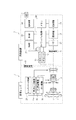
図2は、本実施例の撮像装置1および撮像レンズ2の機能ブロックを示す図である。
図2において、撮像装置1は、焦点検出部12、露出検出部13、撮像素子6、A/D変換部20、画像処理部21、記録処理部23、メモリ24、カメラシステム制御部25、マイク7、音声処理部26、操作部27、表示部22を有する。一方、撮像レンズ2は、撮像光学系3、レンズシステム制御部28、焦点レンズ駆動部9a、ブレ補正駆動部9b、絞り駆動部9cを有する。
Next, functions of the image pickup apparatus 1 of the present embodiment will be described.
FIG. 2 is a diagram illustrating functional blocks of the imaging device 1 and the
In FIG. 2, the imaging device 1 includes a
なお、各機能ブロックは、実際にハードウェアとして独立した構成であっても良いし、複数の機能が、単一のハードウェアによって構成されていても良い。たとえば、カメラシステム制御部25は、CPUとメモリとからなるマイクロコンピュータである。このマイクロコンピュータにより他の機能ブロックの機能を実行させても良い。
Each functional block may actually have an independent configuration as hardware, or a plurality of functions may be configured by a single hardware. For example, the camera
撮像系は、被写体の光学像を撮影光学系3を介して撮像素子6の撮像面に結像する。エイミングなどの撮影予備動作中は、クイックリターンミラー機構11に設けられたミラーにより、撮像素子6に対して光学像を導く代わりに、ファインダー側へ光学像を導くとともに、焦点検出部12にも光束の一部を導く。焦点検出部12の検出結果に基づいて、後述の制御系によって適切に撮影光学系3が調整されることで、適切な光量の物体光を撮像素子6に露光され、撮像素子6近傍で被写体像が結像されるようになる。
The imaging system forms an optical image of the subject on the imaging surface of the imaging device 6 via the imaging optical system 3. During a preliminary shooting operation such as aiming, a mirror provided in the quick
画像処理部21は、A/D変換部20を介して撮像素子6から受けた画像信号を処理する。たとえば、ホワイトバランス回路、ガンマ補正回路、補間演算による高解像度化を行う補間演算回路等を有する。
The
音声処理系は、マイク7により得られた音声信号に対して、音声処理部26によって適切な処理を施して録音用音声信号を生成する。録音用生成信号は後述する記録処理部により画像とリンクして、記録処理部23に送信される。
The audio processing system generates an audio signal for recording by performing appropriate processing on the audio signal obtained by the
記録処理部23は、不図示の記録媒体に対して、画像信号と音声信号からなるストリームデータを記録するものであり、さらに、表示部22に出力する画像を生成する。また、記録処理部23は、予め定められた方法を用いて画像、動画、音声などの圧縮符号化処理を行う。本実施例においては、どのような圧縮符号化処理を用いても構わない。
The
カメラシステム制御部25は、撮像装置1の各ブロックを制御するものである。たとえば、操作部27からの入力に基づいて、撮像の際のタイミング信号などを生成して出力したり、撮像レンズ2の制御部に対して、レンズ駆動用の命令信号を出力したりする。また、カメラシステム制御部25は後述する周囲音レベルの判別手段、周囲音と駆動音の比較手段としても機能する。焦点検出部12は被写体の光学像の合焦状態を、露出検出部13は被写体の輝度を、それぞれ検出する。レンズシステム制御部28は前記カメラシステム制御部25の信号に応じて適切にレンズを駆動させて光学系の調整を行う。
The camera
カメラシステム制御部25は、例えば、操作部27のシャッターレリーズボタンに対応する操作信号を検出して、撮像素子6の駆動、画像処理部21の動作、記録処理部23の圧縮処理などを制御する。さらに表示部22によって光学ファインダー、液晶モニタ等に情報表示を行う情報表示装置の各セグメントの状態を制御する。
For example, the camera
制御系の光学系の調整動作について説明する。カメラシステム制御部25には焦点検出部12および露出検出部13が接続されており、これらの信号を元に適切な焦点位置、絞り位置を求める。カメラシステム制御部25は、電気接点10を介してレンズシステム制御部28に指令を出し、レンズシステム制御部28は焦点レンズ駆動部9aおよび絞り駆動部9cを適切に制御する。さらにレンズシステム制御部28には不図示の手ぶれ検出センサが接続されており、手ぶれ補正を行うモードにおいては、手ぶれ検出センサの信号を元にブレ補正駆動部9bを適切に制御する。
The adjustment operation of the optical system of the control system will be described. A
ここで、いわゆる動画撮影などの音声記録を伴う撮影について説明する。音声記録を伴う撮影においては、カメラ本体およびレンズのアクチュエータ駆動に伴う音(以下 メカ駆動音)は不要な音であり雑音となる。またユーザーのボタン/ダイヤル操作や外装の擦れに伴う音(以下 ユーザー操作音)も同様に不要な音であり雑音となる。以下、本実施例においては雑音とは、ホワイトノイズのような背景雑音ではなく前述したメカ駆動音、ユーザー操作音を指す。 Here, photographing with sound recording such as so-called moving image photographing will be described. When shooting with audio recording, the sound that accompanies the actuator drive of the camera body and lens (hereinafter referred to as “mechanical drive sound”) is an unnecessary sound and is a noise. In addition, the sound that accompanies the user's button / dial operation and the rubbing of the exterior (hereinafter referred to as user operation sound) is also unnecessary sound and becomes noise. Hereinafter, in this embodiment, noise refers to the mechanical drive sound and user operation sound described above, not background noise such as white noise.
図3を用いて、音声記録を伴う撮影における雑音の影響について説明する。図3はカメラの斜視図である。図3には、撮像装置1の操作ボタン31aおよび31b、外部の音声をマイク7に導くためのマイク開口部32が示されている。
With reference to FIG. 3, the influence of noise in shooting with sound recording will be described. FIG. 3 is a perspective view of the camera. FIG. 3 shows
図3から明らかなように、マイク開口部32に対して雑音源である、カメラの操作釦31a/31bおよび撮像装置1または撮像レンズ2内の駆動部(モータやアクチュエータなど)は近接している。
As is clear from FIG. 3, the
一般に被写体は対象が人物であれば、一般的に数メートルから数十メートル、撮像装置から遠い位置にいると考えられる。このような状況においては、雑音源が発生する雑音レベル小さくても、マイク7で取得される人物に対応する音声信号に対する雑音の影響は無視できない。
In general, if the subject is a person, it is generally considered that the subject is at a position far from the imaging device, generally from several meters to several tens of meters. In such a situation, even if the noise level generated by the noise source is low, the influence of noise on the voice signal corresponding to the person acquired by the
そこで本実施例の撮像装置1は、雑音の影響を低減するために、音声処理部26により雑音低減処理が実行される。
Therefore, in the imaging apparatus 1 of the present embodiment, noise reduction processing is executed by the
図4を用いて音声処理部26の動作について説明する。図4は、音声処理部26の機能を説明する為の図である。音声処理部26は、ゲイン調整部41、フィルタ42、A/Dコンバータ43、雑音処理部44、フィルタ45、雑音判定部46を有する。また、雑音処理部44は、予測処理または、フィルタ処理または、MUTE処理を実行することができる。
The operation of the
図4において、マイク7により得られた音声信号はゲイン調整部41に供給される。ゲイン調整部41はA/Dコンバータ43のダイナミックレンジが十分に活用できるようにマイク7の信号レベルを調整する。つまり、マイク7の信号レベルが小さいときはゲインアップして信号を増幅し、マイク7の信号レベルが大きいときはゲインを下げて飽和を防ぐ。
In FIG. 4, the audio signal obtained by the
フィルタ42はA/Dコンバータ43のサンプリング周波数を考慮して適切なカットオフ周波数をもつ低域通過フィルタなどで構成される。マイクが特定の周波数を発する素子の近傍にある場合などは前述の低域通過フィルタに加えて適当なノッチフィルタを含む場合もある。A/Dコンバータ43はゲイン調整部41およびフィルタ42で処理された音声信号をデジタル変換する。
The
雑音処理部44は複数の雑音処理を実行することができる。図4の例では予測処理44a,フィルタ処理44b,MUTE処理44cを実行することができるものとするが、さらに他の処理を実行できでもよい。なお、音声処理部26は、カメラシステム制御部25により制御され、雑音処理部44がいずれの雑音処理を実行するかについても、カメラシステム制御部25により制御される。なお、これら複数の雑音処理は選択的に又は組み合わせて動作させることが出来る。
The noise processing unit 44 can execute a plurality of noise processes. In the example of FIG. 4, it is assumed that the
本実施例のフィルタ処理44bは、音声信号の低域通過や帯域通過など適切な周波数の音声を通過させる処理を行うことによって、雑音を除去するものである。
The
本実施例のMUTE処理44cは、雑音の含まれる区間の音声信号を無音又は所定の音声信号などに置き換えることによって雑音を除去するものである。
本実施例の予測処理44aについては、後述する。
The MUTE processing 44c of the present embodiment removes noise by replacing a voice signal in a section including noise with silence or a predetermined voice signal.
The
フィルタ45は雑音処理を行った後に必要であれば適当なフィルタ処理を施すためのフィルタである。不要であればスルーすることも出来る。
The
雑音判定部46は、被写体音以外の雑音が存在するか否かを判断する。ここで、雑音判定部46の構成の一例を図5に示す。
The
具体的には、雑音が含まれるか否かを判定する区間の音声信号をバッファから読み出し、適当な帯域通過フィルタを施す。なお、この帯域通過フィルタは音声信号が少なく、本件で対象としているメカ駆動音、ユーザー操作音が顕著な領域を通過させるようなものである。例えば、一般的には音声信号よりも高い周波数帯域(5kHz〜10kHz程度)を通過させるような帯域通過フィルタを使用する。 Specifically, an audio signal in a section for determining whether noise is included is read from a buffer, and an appropriate band pass filter is applied. This band-pass filter has a small audio signal, and passes the region where the mechanical drive sound and user operation sound that are the subject of the present application are remarkable. For example, a band pass filter that generally passes a higher frequency band (about 5 kHz to 10 kHz) than the audio signal is used.
次に、帯域通過フィルタ透過後の信号を差分処理によって背景雑音によるDC成分を除去する。帯域通過フィルタの特性によっては差分処理を省略しても良い。さらに、差分処理が実行された音声信号の絶対値を取得し、これらを平滑化させることで、信号のエンベロープを検出する。最後に、得られた信号のエンベロープが閾値を超えているか否かを閾値判断することによって、雑音の有無を判断する。閾値は実験的に求めた値などを予め設定しておく。 Next, the DC component due to background noise is removed from the signal after passing through the band-pass filter by differential processing. Depending on the characteristics of the band pass filter, the difference processing may be omitted. Furthermore, the absolute value of the audio signal that has been subjected to the difference processing is acquired and smoothed to detect the envelope of the signal. Finally, the presence / absence of noise is determined by determining whether or not the envelope of the obtained signal exceeds the threshold. As the threshold value, an experimentally obtained value or the like is set in advance.
図6は雑音判定部46の雑音判定処理の各工程における波形の具体例を示した図である。図6(a)は取得音声を、図6(b)は帯域通過フィルタ通過後の波形を、図6(c)は差分処理後の波形を、図6(d)は絶対値処理後の波形を、図6(e)は平滑化処理後の波形を夫々示している。図6(a)に示した波形は人の声に雑音が重畳した場合を示している。人の声に対して雑音は高周波成分を多く含んでいる。図6(b)から明らかなように、適当な帯域通過フィルタを施すことで雑音部分を効果的に取得できている。図6の例では、図6(c)に示すように、差分処理を行うことで、変化が大きい箇所を強調している。さらに図6(d),(e)に示すように絶対値処理、平滑化処理を施すことで雑音部分にパワーを持つ波形を生成している。そして、図6(e)に示した雑音検出閾値を超えた場合は雑音が発生しているものと判定することが可能となる。
FIG. 6 is a diagram showing a specific example of a waveform in each step of the noise determination process of the
なお、本実施例においては、撮像装置1のカメラシステム制御部25により、撮像レンズ2のレンズシステム制御部28に対してレンズ駆動信号を送信した場合、カメラシステム制御部25は、レンズの駆動によって雑音が発生する期間を把握することができる。したがって、カメラシステム制御部25によってレンズ駆動信号が送信された場合には、その信号の送信時間または、レンズ駆動信号が示すレンズ駆動時間によって雑音の発生する期間を特定することができる。そのため、カメラシステム制御部25は、レンズ駆動信号に基づいて、音声処理部26の雑音処理部44による雑音低減を行う区間を制御することができる。
In the present embodiment, when the camera
次に、雑音判定部による雑音の有無の判定結果と、前述の音声処理部26の動作の関係について説明する。
Next, the relationship between the determination result of the presence / absence of noise by the noise determination unit and the operation of the
本実施例の撮像装置1においては、カメラシステム制御部25は、雑音判定部46の判定結果に応じて、雑音処理部44の動作を切り替えている。
In the imaging apparatus 1 of the present embodiment, the camera
まず、雑音判定部46の判定の結果、雑音が発生していないと判定された区間の音声信号に対しては、雑音処理部44はどの雑音処理も実行しないように設定する。さらにフィルタ45も同様に動作させないように制御する。このときは、A/Dコンバータ43が変換した信号そのものが録音用音声信号としてカメラシステム制御部25に送出される。
First, as a result of the determination by the
また、雑音が局所的に存在する場合は、カメラシステム制御部25からの指令に基づいて音声に対して雑音処理を施す。
When noise is present locally, noise processing is performed on the voice based on a command from the camera
次に図7〜図14を用いて本実施例の信号処理について説明する。
まず、音声処理部26が実行する予測処理について説明する。
予測処理は、例えば、「ITU−T Recommendation G.711−Appendix I」に開示されている信号処理技術を用いている。この技術では、雑音の含まれる区間(雑音発生区間)の信号の近傍の所定区間(参照区間)の信号に基づいて、演算処理により雑音発生区間と置換するための信号を生成する。これにより、雑音やパケットのロスが起きた区間の信号を補間することができる。この演算処理は、例えば、参照区間の信号のピッチ検出を行い、検出されたピッチで参照区間の信号を繰り返した信号を生成してもよい。すなわち、予測処理とは、雑音発生区間の信号をその近傍の所定区間の信号に基づいて生成された信号により置換することで、雑音発生区間の雑音を低減させた信号を取得する処理である。
Next, the signal processing of this embodiment will be described with reference to FIGS.
First, the prediction process performed by the
The prediction processing uses, for example, a signal processing technique disclosed in “ITU-T Recommendation G.711-Appendix I”. In this technique, a signal for replacement with a noise generation section is generated by arithmetic processing based on a signal in a predetermined section (reference section) in the vicinity of a signal in a section including noise (noise generation section). Thereby, it is possible to interpolate a signal in a section where noise or packet loss occurs. In this arithmetic processing, for example, the pitch of the signal in the reference section may be detected, and a signal in which the signal in the reference section is repeated at the detected pitch may be generated. That is, the prediction process is a process of acquiring a signal in which noise in the noise generation section is reduced by replacing the signal in the noise generation section with a signal generated based on a signal in a predetermined section nearby.
図7は、予測処理を模式的に説明する図である。図7において51は雑音の混入の無い信号区間を、52は雑音が混入した区間を(雑音発生区間)、53a,53bは予測処理のための参照区間を、54は予測処理後の信号を示している。 FIG. 7 is a diagram schematically illustrating the prediction process. In FIG. 7, 51 is a signal section without noise, 52 is a section with noise (noise generation section), 53a and 53b are reference sections for prediction processing, and 54 is a signal after prediction processing. ing.
予測処理による信号の生成方法は例えば、特許文献1、特許文献2、非特許文献1の方法などが使用できる。すなわち、雑音発生区間の近傍の所定区間(参照区間)の信号に基づいて、雑音発生区間の信号を生成する方法であれば、公知のどのような処理を用いても良い。
For example, the methods of Patent Literature 1,
図7に示すように、予測処理では、雑音発生区間52が決定されると、その近傍の参照区間53a,53bの信号に基づいて生成された信号を、雑音発生区間52の信号と置換する(予測生成された区間54)ようにしている。
As shown in FIG. 7, in the prediction process, when the
本実施例においては図7に示すように、通常の動作においては雑音区間52の前後の参照区間53a,53bの信号に基づいて雑音区間の信号を生成する。
In this embodiment, as shown in FIG. 7, in a normal operation, a signal in the noise section is generated based on the signals in the
図8は、本実施例の処理を説明するための図である。図8はでは、図7と異なり、雑音が連続して発生し、参照区間の信号にも雑音が重畳されている場合の信号処理を説明する。 FIG. 8 is a diagram for explaining the processing of this embodiment. In FIG. 8, unlike FIG. 7, signal processing in the case where noise is continuously generated and noise is also superimposed on the signal in the reference section will be described.
図8において51は雑音の混入の無い信号区間を、52a,52bは雑音発生区間を示す。また、53a,53bは52aの雑音発生区間に対応する信号を生成するための参照区間を示す。また、54aは52aの予測処理後の信号を、55a,55bは52bを予測処理するために用いる参照区間を、54bは52bの予測処理後の信号を示している。図8の例では雑音52a,52bが時間的に近接して発生したために、参照区間53bに雑音が混入してしまっている。そのために、予測生成された信号54aは雑音52bの影響を受けて、適切ではない信号になっている場合がある。同様に、参照区間55aに雑音の影響を受けた区間54aを用いた結果、予測生成された信号54bも適切ではない信号になっている場合がある。
In FIG. 8, 51 indicates a signal section in which noise is not mixed, and 52a and 52b indicate noise generation sections.
これは、例えば、撮像装置1のカメラシステム制御部25の指示により焦点調整を行うために、焦点レンズ駆動部9aを間欠的かつ時間的に近接させて動作させる場合などに発生する。また、メカ駆動音の発生に近接してユーザーが撮影装置を持ち替えてユーザー操作音が発生する場合などにも発生する。
This occurs, for example, when the focus lens driving unit 9a is operated intermittently and temporally in order to perform focus adjustment according to an instruction from the camera
図9は本発明を適用した場合の信号処理を模式的に説明する図である。
図9において51は雑音の混入の無い信号区間を、52a,52bは雑音発生区間を示す。また、63は52aを予測処理するために用いる参照区間を、54aは52aの予測処理後の信号を示している。また、65は52bを予測処理するために用いる参照区間を、54bは52bの予測処理後の信号を示している。
図9の信号は図8と同じく雑音52a,52bが時間的に近接して発生した例である。
FIG. 9 is a diagram schematically illustrating signal processing when the present invention is applied.
In FIG. 9, 51 indicates a signal section in which noise is not mixed, and 52a and 52b indicate noise generation sections.
The signal of FIG. 9 is an example in which
図9において雑音区間52aを処理する際には、通常であれば、その前後が参照区間の候補となるが、図9の例では、雑音判定部46で処理した結果、時間的に後方の参照区間候補への雑音の混入が検出される。その結果、時間的に後方にあった参照区間候補は使用せずに、雑音区間52aを処理する時には時間的に前方に位置する参照区間63から信号54aを生成する。
一方、雑音区間52bを処理する際には、同様にして参照区間65から信号54bを生成する。
When processing the
On the other hand, when processing the
以上に説明したように、予測処理を実行する際には、雑音発生区間の前後を参照区間とするが、参照区間内に他の雑音が発生している場合には、雑音が発生していない方の参照区間の音声信号に基づいて、予測音声信号を生成する。 As described above, when the prediction process is executed, the reference interval is set before and after the noise generation interval. However, when other noise is generated in the reference interval, no noise is generated. A predicted speech signal is generated based on the speech signal of the other reference section.
そのため、雑音の混入の無い区間を参照するので生成された信号54a,54bは雑音区間52a,52bの影響を受けない。そのため高品位な音声を得ることが可能となる。
For this reason, the
図10は図9を用いて説明した予測処理による音声信号の波形を示す図である。
図10(a)は処理前の波形を示す。
図10(b)は時間的に前方にある雑音を処理した後の波形を示す。
図10(c)は時間的に後方にある雑音を処理した後の波形を示す。
FIG. 10 is a diagram illustrating a waveform of an audio signal obtained by the prediction process described with reference to FIG.
FIG. 10A shows a waveform before processing.
FIG. 10 (b) shows the waveform after processing the noise ahead in time.
FIG. 10 (c) shows the waveform after processing the noise behind in time.
図10(a)においては、参照区間の音声信号に基づいて生成された音声信号により、1つめの雑音を低減することを示している。図9で説明したように、2つめの雑音が1つめの雑音を低減するための参照区間に含まれているため、2つめの雑音を含む区間を参照区間としない処理を示している。 FIG. 10A shows that the first noise is reduced by the audio signal generated based on the audio signal in the reference section. As described with reference to FIG. 9, since the second noise is included in the reference interval for reducing the first noise, the processing including the interval including the second noise as the reference interval is illustrated.
図10(b)においては、2つめの雑音を低減することを示している。図9で説明したように、2つめの雑音の参照区間のうち雑音の含まれていない参照区間の音声信号に基づいて2つめの雑音を低減する処理を示している。 FIG. 10B shows that the second noise is reduced. As described with reference to FIG. 9, the second noise is reduced based on the speech signal in the reference section that does not include noise in the reference section of the second noise.
ここで、本実施例の撮像装置1の音声処理部26による処理手順について図11を用いて説明する。ここでは、雑音発生区間の信号を置換するための信号を生成するための、参照区間を、雑音の前後または、前方のみまたは、後方のみを、参照区間に雑音が含まれるか否かに応じて切替えている。
Here, a processing procedure by the
本実施例の撮像装置1のカメラシステム制御部25は、音声信号処理部26において、雑音判定部46により、マイク7により得られた音声信号を解析させ、雑音の有無を検知させ、雑音発生区間を判定させる。
The camera
そして、カメラシステム制御部25は、雑音発生区間の前後の区間を参照区間とする(S1101)。
Then, the camera
次に、カメラシステム制御部25は、S1101で参照区間に決定した区間に別の雑音発生が含まれるか否かを判定する(S1102)。
Next, the camera
そして、参照区間に別の雑音が含まれない場合(S1102でNo)には、カメラシステム制御部25は、通常の処理として、雑音発生区間の前後両方の参照区間の音声信号を用いて、雑音低減処理のための音声信号を生成するように音声処理部26を制御する(S1110)。
If another noise is not included in the reference section (No in S1102), the camera
また、参照区間に別の雑音が含まれる場合(S1102でYes)には、カメラシステム制御部25は、参照区間のうち別の雑音の含まれている区間を特定する(S1103)。
When another noise is included in the reference section (Yes in S1102), the camera
雑音発生区間の後方の参照区間に別の雑音が含まれている場合(S1103でNo)には、前方の参照区間に基づいて、雑音発生区間の音声信号を補間するための信号を生成するように音声処理部26を制御する(S1120)。一方、雑音発生区間の前方の参照区間に別の雑音が含まれている場合(S1103でYes)には、後方の参照区間に基づいて、雑音発生区間の音声信号を補間するための信号を生成するように音声処理部26を制御する(S1130)。
If another noise is included in the reference interval behind the noise generation interval (No in S1103), a signal for interpolating the audio signal in the noise generation interval is generated based on the reference interval in front. The
そして、カメラシステム制御部25は、S1110、S1120、S1130で生成された補間用の音声信号を用いて雑音発生区間の音声信号を置換するように、音声信号処理部26を制御する(S1140)。
このような処理を繰り返し実行することにより、本実施例の撮像装置1は、雑音を低減しているのである。
Then, the camera
By repeatedly executing such processing, the imaging apparatus 1 of the present embodiment reduces noise.
このように、本実施例の撮像装置1は、音声信号に含まれる雑音を低減することができる。雑音を低減する処理は、雑音の含まれる区間(雑音発生区間)の音声信号の近傍の所定の区間(参照区間)の音声信号に基づいて、雑音発生区間の音声信号を補間する為の信号を生成する。そして、生成した信号で、雑音発生区間の音声信号を補間することにより雑音を低減する。 Thus, the imaging device 1 of the present embodiment can reduce noise included in the audio signal. The process for reducing the noise is a process for interpolating the audio signal in the noise generation interval based on the audio signal in the predetermined interval (reference interval) in the vicinity of the audio signal in the noise-containing interval (noise generation interval). Generate. Then, noise is reduced by interpolating the audio signal in the noise generation section with the generated signal.
このとき、参照区間の音声信号に対して別の雑音が含まれる場合には、雑音の含まれない参照区間の音声信号に基づいて雑音発生区間の音声信号を補間する為の信号を生成するように音声信号処理部26を制御する。
At this time, if another noise is included in the audio signal in the reference interval, a signal for interpolating the audio signal in the noise generation interval is generated based on the audio signal in the reference interval not including noise. The audio
そのため、本実施例の撮像装置1は、雑音発生区間の音声信号を補間する為の信号を生成する際に、他の雑音の影響を少なくすることができるのである。 Therefore, the imaging apparatus 1 according to the present embodiment can reduce the influence of other noise when generating a signal for interpolating the audio signal in the noise generation section.
なお、本実施例の撮像装置は、図9、図10を用いて説明したような、雑音低減処理の他、図12から図16に示すような、他の雑音低減処理を実行することもできる。 Note that the imaging apparatus according to the present exemplary embodiment can execute other noise reduction processes as illustrated in FIGS. 12 to 16 in addition to the noise reduction processes described with reference to FIGS. 9 and 10. .
図12、図13は、他の雑音低減処理について説明する為の図である。図12において51は雑音の混入の無い信号区間を、52a,52bは雑音区間を示す。また、63は52aを予測処理するために用いる参照区間を、54aは52aの予測処理後の信号を示す。65a,65bは52bを予測処理するために用いる参照区間を、54bは52bの予測処理後の信号を示す。
12 and 13 are diagrams for explaining other noise reduction processing. In FIG. 12, 51 indicates a signal section in which noise is not mixed, and 52a and 52b indicate noise sections.
図12の信号は図8および図9と同じく雑音52a,52bが時間的に近接して発生した例である。図12において雑音区間52a(第1の区間)を処理する際にはその前後が参照区間の候補となるが、時間的に後方の参照区間に別の雑音が含まれることになる。
The signal shown in FIG. 12 is an example in which
そこで、カメラシステム制御部25は、雑音区間52aを補間するための信号54aを、時間的に前方に位置する参照区間63に基づいて生成する。ここまでは図9と同様の処理である。
Therefore, the camera
次に、雑音区間52b(第2の区間)の音声信号を処理する際には、既に処理を行った区間54aについては、雑音低減処理が行われた後であるため、雑音の混入が無い区間として取り扱う。そのため、音声信号処理部46は、雑音区間52bを補間するための音声信号を、参照区間65a,65bの音声信号に基づいて生成する。
Next, when processing the audio signal in the
このような処理によっても、雑音を含む音声信号を使用せずに雑音発生区間52a、52bの音声信号を補間するための音声信号を生成することができ、他の雑音の影響を少なくすることができるのである。
Even with such processing, it is possible to generate an audio signal for interpolating the audio signals in the
図13は図12を用いて説明した波形を処理した例を示す図である。
図13(a)は処理前の波形を示す。
図13(b)は時間的に前方にある雑音を処理した後の波形を示す。
図13(c)は時間的に後方にある雑音を処理した後の波形を示す。
FIG. 13 is a diagram illustrating an example in which the waveform described with reference to FIG. 12 is processed.
FIG. 13A shows a waveform before processing.
FIG. 13 (b) shows the waveform after processing the noise ahead in time.
FIG. 13 (c) shows the waveform after processing the noise behind in time.
図13(a)においては、参照区間の音声信号に基づいて生成された音声信号により、1つめの雑音を低減することを示している。図12で説明したように、2つめの雑音が1つめの雑音を低減するための参照区間に含まれているため、2つめの雑音を含む区間を参照区間とせずに、雑音発生区間の前方の参照区間の音声信号に基づいて処理を行うこと示している。 FIG. 13A shows that the first noise is reduced by the audio signal generated based on the audio signal in the reference section. As described with reference to FIG. 12, the second noise is included in the reference interval for reducing the first noise, and therefore, the interval including the second noise is not used as the reference interval, but the front of the noise generation interval. This indicates that processing is performed based on the audio signal in the reference section.
図13(b)においては、2つめの雑音を低減することを示している。図12で説明したように、2つめの雑音の参照区間のうち1つめの雑音の含まれていた区間のも参照区間として、雑音発生区間の前後の参照区間の音声信号に基づいて、2つめの雑音を低減する処理を示している。 FIG. 13B shows that the second noise is reduced. As described with reference to FIG. 12, the second noise reference section including the first noise is also used as the reference section based on the audio signals in the reference sections before and after the noise generation section. The process which reduces the noise of is shown.
図12、図13の処理は、連続した雑音を含む音声信号の雑音低減処理を行う場合には、第1の雑音発生区間の雑音を低減する場合には、第1の雑音発生区間の近傍の所定区間の音声信号に基づいて生成された信号で、第1の雑音発生区間の音声を補間する。このとき、参照区間の音声信号に別の雑音が含まれる場合には、別の雑音が含まれていない参照区間の音声信号に基づいて生成された信号で、第1の雑音発生区間の音声を補間する。そして、第2の雑音発生区間の雑音を低減する場合には、第2の雑音発生区間の近傍の所定区間の音声信号に基づいて生成された信号で、第2の雑音発生区間の音声を補間する。このとき、参照区間の一部が第1の雑音発生区間と重なる場合であっても、第1の雑音発生区間の雑音低減処理が実行された後であれば、その参照区間の音声信号に基づいて、第2の雑音発生区間の音声を補間する信号を生成する。 The processing of FIGS. 12 and 13 is performed when noise reduction processing is performed on an audio signal including continuous noise, and when noise in the first noise generation section is reduced, The voice generated in the first noise generation section is interpolated with a signal generated based on the voice signal in the predetermined section. At this time, when another noise is included in the audio signal in the reference section, the sound in the first noise generation section is generated using a signal generated based on the audio signal in the reference section that does not include another noise. Interpolate. When the noise in the second noise generation section is reduced, the voice in the second noise generation section is interpolated with the signal generated based on the voice signal in the predetermined section near the second noise generation section. To do. At this time, even if a part of the reference section overlaps with the first noise generation section, if the noise reduction processing of the first noise generation section is performed, the reference section is based on the audio signal of the reference section. Thus, a signal for interpolating the voice in the second noise generation section is generated.
つまり、第1の雑音発生区間の補間後の音声信号を用いて、第2の雑音発生区間の音声信号を補間するための信号を生成するのである。 That is, a signal for interpolating the audio signal in the second noise generation interval is generated using the audio signal after interpolation in the first noise generation interval.
さらに他の雑音低減処理について説明する。図14、図15は、他の雑音低減処理について説明する為の図である。図14において51は雑音の混入の無い信号区間を、52a,52bは雑音区間を示す。また、63は52aを予測処理するために用いる参照区間を、54aは52aの予測処理により補間された区間を示す。また、65a,65bは52bを予測処理するために用いる参照区間を示す。また、54bは52bの予測処理により補間された区間を示す。また、67a,67bは54aを予測処理するために用いる参照区間を示す。また、54cは54aの予測処理により補間された区間を示す。
Still another noise reduction process will be described. 14 and 15 are diagrams for explaining other noise reduction processing. In FIG. 14,
図14の信号は図8、図9および図12と同じく雑音52a,52bが時間的に近接して発生した例である。図14において雑音区間52aを処理する際にはその前後が参照区間の候補となるが、時間的に後方の参照区間には別の雑音が含まれることになる。
The signal of FIG. 14 is an example in which
そこで、カメラシステム制御部25は、雑音区間52aを補間するための信号54aを、時間的に前方に位置する参照区間63に基づいて生成する。ここまでは図9と同様の処理である。
Therefore, the camera
次に、雑音区間52bの音声信号を処理する際には、既に処理を行った区間54aについては、雑音低減処理が行われた後であるため、雑音の混入が無い区間として取り扱う。そのため、音声信号処理部46は、雑音区間52bを補間するための音声信号を、参照区間65a,65bの音声信号に基づいて生成する。ここまでは図12と同様の処理である。
Next, when processing the audio signal in the
図14においては、信号54aにより補間された区間の音声信号をさらに補間する処理を行う。すなわち、信号54aは、雑音発生区間52aの時間的に前方の参照区間の音声信号に基づいて生成された信号であり、後方の参照区間の音声信号を使用していない。そのため、再度、雑音発生区間52bの補間後の音声信号を含む後方の参照区間67bの音声信号と、前方の参照区間67aの音声信号に基づいて、補間信号54cを生成するのである。
このような処理によって、さらに雑音低減後の音声信号の音質を向上させることができる。
In FIG. 14, a process of further interpolating the audio signal in the section interpolated by the
Such processing can further improve the sound quality of the audio signal after noise reduction.
なお、さらに予測処理を繰り返して信号の差が小さくなるまで処理を行っても良い。図14の例では信号54aと54cの差が十分小さければその信号を採用する。大きい場合は54cを用いて再度54bを処理した後に54cを処理する。
Further, the prediction process may be repeated until the signal difference is reduced. In the example of FIG. 14, if the difference between the
図15は図14を用いて説明した波形を処理した例を示す図である。
図15(a)は処理前の波形を示す。
図15(b)は時間的に前方にある雑音を処理した後の波形を示す。
図15(c)は時間的に後方にある雑音を処理した後の波形を示す。
図15(d)は時間的に前方にある雑音を再度処理した後の波形を示す。
図15(e)は1回目の時間的に前方にある雑音を処理による信号の変化(図15(a)と図15(b)の波形の差)を示す。
FIG. 15 is a diagram illustrating an example in which the waveform described with reference to FIG. 14 is processed.
FIG. 15A shows a waveform before processing.
FIG. 15 (b) shows the waveform after processing the noise ahead in time.
FIG. 15 (c) shows the waveform after processing the noise behind in time.
FIG. 15 (d) shows the waveform after the noise that is ahead in time is processed again.
FIG. 15E shows a change in signal (difference between waveforms in FIG. 15A and FIG. 15B) due to processing of noise in front of the first time.
図15(a)においては、参照区間の音声信号に基づいて生成された音声信号により、1つめの雑音を低減することを示している。図14で説明したように、2つめの雑音が1つめの雑音を低減するための参照区間に含まれているため、2つめの雑音を含む区間を参照区間とせずに、雑音発生区間の前方の参照区間の音声信号に基づいて処理を行うこと示している。 FIG. 15A shows that the first noise is reduced by an audio signal generated based on the audio signal in the reference section. As described with reference to FIG. 14, the second noise is included in the reference interval for reducing the first noise, and therefore, the interval including the second noise is not set as the reference interval, but the front of the noise generation interval. This indicates that processing is performed based on the audio signal in the reference section.
図15(b)においては、2つめの雑音を低減することを示している。図14で説明したように、2つめの雑音の参照区間のうち1つめの雑音の含まれていた区間のも参照区間として、雑音発生区間の前後の参照区間の音声信号に基づいて、2つめの雑音を低減する処理を示している。 FIG. 15B shows that the second noise is reduced. As described with reference to FIG. 14, the first noise-containing section of the second noise reference section is also used as the reference section based on the audio signals in the reference sections before and after the noise generation section. The process which reduces the noise of is shown.
図15(c)においては、さらに、1つめの雑音の発生していた区間の音声信号をその区間の前後の参照区間の音声信号に基づいて生成された信号で補間することを示している。 FIG. 15C further shows that the speech signal in the section where the first noise is generated is interpolated with a signal generated based on the speech signals in the reference sections before and after the section.
以上、本発明の好ましい実施形態について説明したが、本発明はこれらの実施形態に限定されず、その要旨の範囲内で種々の変形及び変更が可能である。 As mentioned above, although preferable embodiment of this invention was described, this invention is not limited to these embodiment, A various deformation | transformation and change are possible within the range of the summary.
本実施例においては、撮像装置を一例として説明したが、音声信号を処理することができる装置であればどのような装置であっても良い。例えば、コンピュータ、携帯電話、ゲーム機などの音声を取り扱うことができる装置であればどのような装置であっても良い。また、コンピュータに上述した処理を実行させる為のプログラムも本発明の思想に含まれる。 In the present embodiment, the imaging apparatus has been described as an example, but any apparatus may be used as long as it can process an audio signal. For example, any device that can handle sound, such as a computer, a mobile phone, and a game machine, may be used. A program for causing a computer to execute the above-described processing is also included in the concept of the present invention.
(他の実施形態)
上述の実施形態は、システム或は装置のコンピュータ(或いはCPU、MPU等)によりソフトウェア的に実現することも可能である。従って、上述の実施形態をコンピュータで実現するために、該コンピュータに供給されるコンピュータプログラム自体も本発明を実現するものである。つまり、上述の実施形態の機能を実現するためのコンピュータプログラム自体も本発明の一つである。
(Other embodiments)
The above-described embodiment can also be realized in software by a computer of a system or apparatus (or CPU, MPU, etc.). Therefore, the computer program itself supplied to the computer in order to implement the above-described embodiment by the computer also realizes the present invention. That is, the computer program itself for realizing the functions of the above-described embodiments is also one aspect of the present invention.
なお、上述の実施形態を実現するためのコンピュータプログラムは、コンピュータで読み取り可能であれば、どのような形態であってもよい。例えば、オブジェクトコード、インタプリタにより実行されるプログラム、OSに供給するスクリプトデータ等で構成することができるが、これらに限るものではない。上述の実施形態を実現するためのコンピュータプログラムは、記憶媒体又は有線/無線通信によりコンピュータに供給される。プログラムを供給するための記憶媒体としては、例えば、フレキシブルディスク、ハードディスク、磁気テープ等の磁気記憶媒体、MO、CD、DVD等の光/光磁気記憶媒体、不揮発性の半導体メモリなどがある。 The computer program for realizing the above-described embodiment may be in any form as long as it can be read by a computer. For example, it can be composed of object code, a program executed by an interpreter, script data supplied to the OS, but is not limited thereto. A computer program for realizing the above-described embodiment is supplied to a computer via a storage medium or wired / wireless communication. Examples of the storage medium for supplying the program include a magnetic storage medium such as a flexible disk, a hard disk, and a magnetic tape, an optical / magneto-optical storage medium such as an MO, CD, and DVD, and a nonvolatile semiconductor memory.
有線/無線通信を用いたコンピュータプログラムの供給方法としては、コンピュータネットワーク上のサーバを利用する方法がある。この場合、本発明を形成するコンピュータプログラムとなりうるデータファイル(プログラムファイル)をサーバに記憶しておく。プログラムファイルとしては、実行形式のものであっても、ソースコードであっても良い。そして、このサーバにアクセスしたクライアントコンピュータに、プログラムファイルをダウンロードすることによって供給する。この場合、プログラムファイルを複数のセグメントファイルに分割し、セグメントファイルを異なるサーバに分散して配置することも可能である。つまり、上述の実施形態を実現するためのプログラムファイルをクライアントコンピュータに提供するサーバ装置も本発明の一つである。 As a computer program supply method using wired / wireless communication, there is a method of using a server on a computer network. In this case, a data file (program file) that can be a computer program forming the present invention is stored in the server. The program file may be an executable format or a source code. Then, the program file is supplied by downloading to a client computer that has accessed the server. In this case, the program file can be divided into a plurality of segment files, and the segment files can be distributed and arranged on different servers. That is, a server apparatus that provides a client computer with a program file for realizing the above-described embodiment is also one aspect of the present invention.
また、上述の実施形態を実現するためのコンピュータプログラムを暗号化して格納した記憶媒体を配布し、所定の条件を満たしたユーザに、暗号化を解く鍵情報を供給し、ユーザの有するコンピュータへのインストールを許可してもよい。鍵情報は、例えばインターネットを介してホームページからダウンロードさせることによって供給することができる。また、上述の実施形態を実現するためのコンピュータプログラムは、すでにコンピュータ上で稼働するOSの機能を利用するものであってもよい。さらに、上述の実施形態を実現するためのコンピュータプログラムは、その一部をコンピュータに装着される拡張ボード等のファームウェアで構成してもよいし、拡張ボード等が備えるCPUで実行するようにしてもよい。
In addition, a storage medium in which the computer program for realizing the above-described embodiment is encrypted and distributed is distributed, and key information for decrypting is supplied to a user who satisfies a predetermined condition, and the user's computer Installation may be allowed. The key information can be supplied by being downloaded from a homepage via the Internet, for example. Further, the computer program for realizing the above-described embodiment may use an OS function already running on the computer. Further, a part of the computer program for realizing the above-described embodiment may be configured by firmware such as an expansion board attached to the computer, or may be executed by a CPU provided in the expansion board. Good.
Claims (7)
前記取得手段により取得された前記音声信号のうち雑音の含まれる雑音区間の前方の所定区間及び後方の所定区間の音声信号を用いて補間用の信号を生成し、前記補間用の信号によって前記雑音区間の音声信号を補間することにより前記音声信号に含まれる雑音を低減する音声処理手段とを有し、
前記音声処理手段は、前記取得手段により取得された前記音声信号のうち前記雑音区間の前方の所定区間と後方の所定区間のいずれか一方の区間に雑音が含まれ、他方の区間に雑音が含まれていない場合は、前記他方の区間の音声信号を用い、前記一方の区間の音声信号を用いることなく前記補間用の信号を生成することを特徴とする音声処理装置。 An acquisition means for acquiring an audio signal;
A signal for interpolation is generated using a voice signal in a predetermined section before and after a noise section including noise in the voice signal acquired by the acquisition means, and the noise is generated by the signal for interpolation. Voice processing means for reducing noise included in the voice signal by interpolating the voice signal of the section ;
Said voice processing means, the noise is included in one section of the front in the predetermined section and the rear of a predetermined interval of said noise interval of the audio signal acquired by the acquisition means, includes the noise in the other section If not , the audio signal of the other section is used, and the interpolating signal is generated without using the audio signal of the one section .
前記取得手段により取得された前記音声信号のうち雑音の含まれる雑音区間の前方の第1の所定区間及び後方の第2の所定区間の音声信号を用いて補間用の信号を生成し、前記補間用の信号によって前記雑音区間の音声信号を補間することにより前記音声信号に含まれる雑音を低減する音声処理手段とを有し、An interpolation signal is generated by using the audio signals in the first predetermined interval and the second predetermined interval behind the noise interval including noise in the audio signal acquired by the acquisition unit, and the interpolation Audio processing means for reducing noise included in the audio signal by interpolating the audio signal in the noise section with a signal for
前記音声処理手段は、前記第1の所定区間に雑音が含まれ、前記第2の所定区間に雑音が含まれない場合、前記第2の所定区間の音声信号を用い、前記第1の所定区間の音声信号を用いることなく前記補間用の信号を生成し、前記第2の所定区間に雑音が含まれ、前記第1の所定区間に雑音が含まれない場合、前記第1の所定区間の音声信号を用い、前記第2の所定区間の音声信号を用いることなく前記補間用の信号を生成することを特徴とする音声処理装置。When the first predetermined section includes noise and the second predetermined section does not include noise, the sound processing means uses the second predetermined section as a sound signal, and uses the first predetermined section. If the interpolation signal is generated without using the voice signal of the first and the second predetermined section includes noise and the first predetermined section does not include noise, the voice of the first predetermined section is generated. A speech processing apparatus using the signal to generate the interpolation signal without using the speech signal in the second predetermined section.
前記光学手段の駆動を制御する制御手段とを有し、
前記判定手段は、前記制御手段により前記光学手段を駆動する指示に基づいて、前記雑音区間を判定することを特徴とする請求項3に記載の音声処理装置。 Optical means for acquiring an optical image of a subject and inputting it to a photoelectric conversion element;
Control means for controlling the driving of the optical means,
The determination means, based on an instruction for driving the optical means by said control means, the speech processing apparatus according to claim 3, wherein the determining the noise section.
前記取得手段により取得された前記音声信号のうち雑音の含まれる雑音区間の前方の所定区間および後方の所定区間の音声信号を用いて補間用の信号を生成し、前記補間用の信号によって前記雑音区間の音声信号を補間することにより、前記音声信号に含まれる雑音を低減する音声処理ステップを有し、
前記音声処理ステップは、前記取得手段により取得された前記音声信号のうち前記雑音区間の前方の所定区間と後方の所定区間のいずれか一方の区間に雑音が含まれ、他方の区間に雑音が含まれていない場合は、前記他方の区間の音声信号を用い、前記一方の区間の音声信号を用いること無く前記補間用の信号を生成することを特徴とする音声処理装置の制御方法。 A method for controlling an audio processing device having an acquisition means for acquiring an audio signal,
Using forward speech signals in the predetermined section and the rear of the predetermined section of the noise interval included noisy of the acquired audio signal to generate a signal for interpolation by the acquisition unit, the noise by the signal for the interpolation A voice processing step of reducing noise included in the voice signal by interpolating a voice signal of a section ;
Said voice processing step, noise included in one section of the front in the predetermined section and the rear of a predetermined interval of said noise interval of the audio signal acquired by the acquisition means, includes the noise in the other section If not , the audio signal of the other section is used, and the interpolating signal is generated without using the audio signal of the one section .
前記取得手段により取得された前記音声信号のうち雑音の含まれる雑音区間の前方の第1の所定区間および後方の第2の所定区間の音声信号を用いて補間用の信号を生成し、前記補間用の信号によって前記雑音区間の音声信号を補間することにより、前記音声信号に含まれる雑音を低減する音声処理ステップを有し、Generating a signal for interpolation using a speech signal in a first predetermined interval and a second predetermined interval behind a noise interval including noise in the audio signal acquired by the acquisition unit; A voice processing step of reducing noise included in the voice signal by interpolating the voice signal in the noise section with a signal for
前記音声処理ステップは、前記第1の所定区間に雑音が含まれ、前記第2の所定区間に雑音が含まれない場合、前記第2の所定区間の音声信号を用い、前記第1の所定区間の音声信号を用いることなく前記補間用の信号を生成し、前記第2の所定区間に雑音が含まれ、前記第1の所定区間に雑音が含まれない場合、前記第1の所定区間の音声信号を用い、前記第2の所定区間の音声信号を用いることなく前記補間用の信号を生成することを特徴とする音声処理装置の制御方法。In the voice processing step, when the first predetermined section includes noise and the second predetermined section does not include noise, the voice processing step uses the voice signal of the second predetermined section, and the first predetermined section If the interpolation signal is generated without using the voice signal of the first and the second predetermined section includes noise and the first predetermined section does not include noise, the voice of the first predetermined section is generated. A method for controlling a speech processing apparatus, comprising: generating a signal for interpolation without using a speech signal in the second predetermined section using a signal.
Priority Applications (3)
| Application Number | Priority Date | Filing Date | Title |
|---|---|---|---|
| JP2012046791A JP6061476B2 (en) | 2012-03-02 | 2012-03-02 | Audio processing device |
| US13/779,605 US9275624B2 (en) | 2012-03-02 | 2013-02-27 | Audio processing apparatus |
| CN201310067156.7A CN103297687B (en) | 2012-03-02 | 2013-03-04 | Audio processing equipment and control method thereof |
Applications Claiming Priority (1)
| Application Number | Priority Date | Filing Date | Title |
|---|---|---|---|
| JP2012046791A JP6061476B2 (en) | 2012-03-02 | 2012-03-02 | Audio processing device |
Publications (2)
| Publication Number | Publication Date |
|---|---|
| JP2013182185A JP2013182185A (en) | 2013-09-12 |
| JP6061476B2 true JP6061476B2 (en) | 2017-01-18 |
Family
ID=49042855
Family Applications (1)
| Application Number | Title | Priority Date | Filing Date |
|---|---|---|---|
| JP2012046791A Active JP6061476B2 (en) | 2012-03-02 | 2012-03-02 | Audio processing device |
Country Status (3)
| Country | Link |
|---|---|
| US (1) | US9275624B2 (en) |
| JP (1) | JP6061476B2 (en) |
| CN (1) | CN103297687B (en) |
Families Citing this family (2)
| Publication number | Priority date | Publication date | Assignee | Title |
|---|---|---|---|---|
| JP2012203040A (en) * | 2011-03-23 | 2012-10-22 | Canon Inc | Sound signal processing apparatus and its control method |
| US9667857B2 (en) * | 2014-10-09 | 2017-05-30 | Panasonic Intellectual Property Management Co., Ltd. | Imaging apparatus with adjustable noise level reduction |
Family Cites Families (7)
| Publication number | Priority date | Publication date | Assignee | Title |
|---|---|---|---|---|
| JP3596978B2 (en) * | 1996-05-14 | 2004-12-02 | 株式会社ルネサステクノロジ | Audio playback device |
| JP4466384B2 (en) | 2005-01-19 | 2010-05-26 | カシオ計算機株式会社 | Electronic camera, noise reduction device, and noise reduction method |
| US7596231B2 (en) * | 2005-05-23 | 2009-09-29 | Hewlett-Packard Development Company, L.P. | Reducing noise in an audio signal |
| JP2008053802A (en) | 2006-08-22 | 2008-03-06 | Sony Corp | Recorder, noise removing method, and noise removing device |
| JP5351644B2 (en) | 2009-07-27 | 2013-11-27 | キヤノン株式会社 | Audio recording apparatus and method, and imaging apparatus |
| JP5538918B2 (en) * | 2010-01-19 | 2014-07-02 | キヤノン株式会社 | Audio signal processing apparatus and audio signal processing system |
| JP5529635B2 (en) * | 2010-06-10 | 2014-06-25 | キヤノン株式会社 | Audio signal processing apparatus and audio signal processing method |
-
2012
- 2012-03-02 JP JP2012046791A patent/JP6061476B2/en active Active
-
2013
- 2013-02-27 US US13/779,605 patent/US9275624B2/en active Active
- 2013-03-04 CN CN201310067156.7A patent/CN103297687B/en active Active
Also Published As
| Publication number | Publication date |
|---|---|
| CN103297687A (en) | 2013-09-11 |
| US20130230189A1 (en) | 2013-09-05 |
| US9275624B2 (en) | 2016-03-01 |
| CN103297687B (en) | 2016-10-05 |
| JP2013182185A (en) | 2013-09-12 |
Similar Documents
| Publication | Publication Date | Title |
|---|---|---|
| JP5529635B2 (en) | Audio signal processing apparatus and audio signal processing method | |
| JP5351644B2 (en) | Audio recording apparatus and method, and imaging apparatus | |
| JP2012142745A (en) | Audio signal processing device, audio signal processing method and program | |
| US8698911B2 (en) | Sound recording device, imaging device, photographing device, optical device, and program | |
| JP6610725B2 (en) | Sound processing apparatus and sound processing program | |
| JP5963430B2 (en) | Imaging apparatus, audio processing apparatus, and control method thereof | |
| JP6061476B2 (en) | Audio processing device | |
| US9288370B2 (en) | Imaging apparatus and audio processing apparatus | |
| JP2011095567A (en) | Imaging device | |
| JP5932399B2 (en) | Imaging apparatus and sound processing apparatus | |
| JP5278477B2 (en) | Signal processing apparatus, imaging apparatus, and signal processing program | |
| JP5839795B2 (en) | Imaging apparatus and information processing system | |
| JP5158054B2 (en) | Recording device, imaging device, and program | |
| JP6144945B2 (en) | Signal processing apparatus and method | |
| JP2012185445A (en) | Signal processor, imaging apparatus and program | |
| JP5473786B2 (en) | Audio signal processing apparatus and control method thereof | |
| JP2012165219A (en) | Imaging apparatus | |
| JP5736839B2 (en) | Signal processing apparatus, imaging apparatus, and program | |
| JP2018207316A (en) | Voice processing apparatus and control method thereof | |
| JP6731772B2 (en) | Electronic device and control method | |
| JP2016054462A (en) | Electronic apparatus and control method | |
| JP2013178456A (en) | Signal processor, camera and signal processing program | |
| JP2016018082A (en) | Voice processing device and method, as well as imaging device | |
| JP2017204715A (en) | Electronic equipment and control method | |
| JP2016053697A (en) | Electronic apparatus and control method |
Legal Events
| Date | Code | Title | Description |
|---|---|---|---|
| A621 | Written request for application examination |
Free format text: JAPANESE INTERMEDIATE CODE: A621 Effective date: 20150302 |
|
| A131 | Notification of reasons for refusal |
Free format text: JAPANESE INTERMEDIATE CODE: A131 Effective date: 20160405 |
|
| A521 | Request for written amendment filed |
Free format text: JAPANESE INTERMEDIATE CODE: A523 Effective date: 20160602 |
|
| TRDD | Decision of grant or rejection written | ||
| A01 | Written decision to grant a patent or to grant a registration (utility model) |
Free format text: JAPANESE INTERMEDIATE CODE: A01 Effective date: 20161115 |
|
| A61 | First payment of annual fees (during grant procedure) |
Free format text: JAPANESE INTERMEDIATE CODE: A61 Effective date: 20161213 |
|
| R151 | Written notification of patent or utility model registration |
Ref document number: 6061476 Country of ref document: JP Free format text: JAPANESE INTERMEDIATE CODE: R151 |