JP6497842B2 - Inkjet recording head inspection apparatus and inspection method - Google Patents
Inkjet recording head inspection apparatus and inspection method Download PDFInfo
- Publication number
- JP6497842B2 JP6497842B2 JP2013260499A JP2013260499A JP6497842B2 JP 6497842 B2 JP6497842 B2 JP 6497842B2 JP 2013260499 A JP2013260499 A JP 2013260499A JP 2013260499 A JP2013260499 A JP 2013260499A JP 6497842 B2 JP6497842 B2 JP 6497842B2
- Authority
- JP
- Japan
- Prior art keywords
- recording head
- ink
- inspection
- ejection
- positional deviation
- Prior art date
- Legal status (The legal status is an assumption and is not a legal conclusion. Google has not performed a legal analysis and makes no representation as to the accuracy of the status listed.)
- Active
Links
Images


Classifications
-
- B—PERFORMING OPERATIONS; TRANSPORTING
- B41—PRINTING; LINING MACHINES; TYPEWRITERS; STAMPS
- B41J—TYPEWRITERS; SELECTIVE PRINTING MECHANISMS, i.e. MECHANISMS PRINTING OTHERWISE THAN FROM A FORME; CORRECTION OF TYPOGRAPHICAL ERRORS
- B41J2/00—Typewriters or selective printing mechanisms characterised by the printing or marking process for which they are designed
- B41J2/005—Typewriters or selective printing mechanisms characterised by the printing or marking process for which they are designed characterised by bringing liquid or particles selectively into contact with a printing material
- B41J2/01—Ink jet
- B41J2/21—Ink jet for multi-colour printing
- B41J2/2132—Print quality control characterised by dot disposition, e.g. for reducing white stripes or banding
- B41J2/2135—Alignment of dots
-
- B—PERFORMING OPERATIONS; TRANSPORTING
- B41—PRINTING; LINING MACHINES; TYPEWRITERS; STAMPS
- B41J—TYPEWRITERS; SELECTIVE PRINTING MECHANISMS, i.e. MECHANISMS PRINTING OTHERWISE THAN FROM A FORME; CORRECTION OF TYPOGRAPHICAL ERRORS
- B41J2/00—Typewriters or selective printing mechanisms characterised by the printing or marking process for which they are designed
- B41J2/005—Typewriters or selective printing mechanisms characterised by the printing or marking process for which they are designed characterised by bringing liquid or particles selectively into contact with a printing material
- B41J2/01—Ink jet
- B41J2/17—Ink jet characterised by ink handling
- B41J2/175—Ink supply systems ; Circuit parts therefor
- B41J2/17503—Ink cartridges
- B41J2/17553—Outer structure
-
- B—PERFORMING OPERATIONS; TRANSPORTING
- B41—PRINTING; LINING MACHINES; TYPEWRITERS; STAMPS
- B41J—TYPEWRITERS; SELECTIVE PRINTING MECHANISMS, i.e. MECHANISMS PRINTING OTHERWISE THAN FROM A FORME; CORRECTION OF TYPOGRAPHICAL ERRORS
- B41J2/00—Typewriters or selective printing mechanisms characterised by the printing or marking process for which they are designed
- B41J2/005—Typewriters or selective printing mechanisms characterised by the printing or marking process for which they are designed characterised by bringing liquid or particles selectively into contact with a printing material
- B41J2/01—Ink jet
- B41J2/21—Ink jet for multi-colour printing
- B41J2/2132—Print quality control characterised by dot disposition, e.g. for reducing white stripes or banding
- B41J2/2142—Detection of malfunctioning nozzles
-
- B—PERFORMING OPERATIONS; TRANSPORTING
- B41—PRINTING; LINING MACHINES; TYPEWRITERS; STAMPS
- B41J—TYPEWRITERS; SELECTIVE PRINTING MECHANISMS, i.e. MECHANISMS PRINTING OTHERWISE THAN FROM A FORME; CORRECTION OF TYPOGRAPHICAL ERRORS
- B41J29/00—Details of, or accessories for, typewriters or selective printing mechanisms not otherwise provided for
- B41J29/38—Drives, motors, controls or automatic cut-off devices for the entire printing mechanism
Description
本発明は、画像を記録するためにインクを吐出可能なインクジェット記録ヘッドの検査装置および検査方法に関するものである。 The present invention relates to an inspection apparatus and an inspection method for an ink jet recording head capable of ejecting ink to record an image.
インクを吐出可能なインクジェット記録ヘッドの製造工程においては、製造された記録ヘッドのインクの吐出性能を検査するために、記録ヘッドから吐出されるインク滴の着弾位置を検出する検査工程が含まれている。 The manufacturing process of an ink jet recording head capable of ejecting ink includes an inspection process for detecting the landing position of an ink droplet ejected from the recording head in order to inspect the ink ejection performance of the manufactured recording head. Yes.
このような記録ヘッドの検査方法としては、例えば、特許文献1に記載された方法が知られている。この方法によれば、記録ヘッドから吐出されるインク滴を受ける媒体を移動させつつ、記録ヘッドからインクを吐出することにより、その媒体上にインクのトッドを形成して、検査パターンを記録する。そして、その検査パターンの画像を読み取って画像処理し、インク滴によって媒体上に形成されたドットの位置のずれ量を求めて、記録ヘッドのインクの吐出性能を評価する。
As such a recording head inspection method, for example, a method described in
このような検査方法を実施する検査工程は、通常、記録ヘッドを製造する全自動の組立工程の中に組み込まれるため、検査工程の前後の工程を実施するための装置の振動、および検査工程を実施する装置の振動の影響を受けるおそれがある。例えば、それらの振動の影響により、検査パターンの記録時におけるインク滴の着弾精度、および検査パターンの記録画像の読み取り精度が低下して、記録ヘッドの吐出状態を正確に評価できなくなるおそれがある。特に、近年の記録ヘッドは、インク滴のサイズが小さくなり、画像の記録解像度が増大し、インクを吐出する吐出口の数も増大しているため、検査パターンを記録するときのインク滴の着弾精度をより高めることが要求されている。 Since the inspection process for carrying out such an inspection method is usually incorporated in a fully automatic assembly process for manufacturing a recording head, the vibration of the apparatus for performing the processes before and after the inspection process, and the inspection process are performed. There is a risk of being affected by the vibration of the device to be implemented. For example, due to the influence of these vibrations, there is a possibility that the landing accuracy of the ink droplets at the time of recording the test pattern and the reading accuracy of the recorded image of the test pattern are lowered, and the ejection state of the recording head cannot be accurately evaluated. In particular, in recent recording heads, the size of ink droplets has decreased, the recording resolution of images has increased, and the number of ejection ports for ejecting ink has also increased, so that the landing of ink droplets when recording a test pattern There is a demand for higher accuracy.
本発明の目的は、インクジェット記録ヘッドのインクの吐出状態を高精度に検査することができるインクジェット記録ヘッドの検査装置および検査方法を提供することにある。 An object of the present invention is to provide an inspection apparatus and an inspection method for an ink jet recording head that can inspect the ink ejection state of the ink jet recording head with high accuracy.
本発明のインクジェット記録ヘッドの検査装置は、吐出口列を形成する複数の吐出口からインクを吐出可能なインクジェット記録ヘッドの検査装置であって、前記複数の吐出口を複数のブロックに分けて、前記複数の吐出口からのインクの吐出タイミングを前記ブロック毎にずらすように前記インクジェット記録ヘッドを時分割駆動することにより、記録媒体に、前記複数のブロックのそれぞれに属する前記吐出口によって所定の検査パターンを記録する制御手段と、前記記録媒体に記録された前記検査パターンを読み取る読み取り手段と、前記読み取り手段によって読み取った前記検査パターンの画像データを画像処理して、前記吐出口から吐出されるインクによって前記記録媒体に形成されるドットの位置ずれ量を取得する取得手段と、前記取得手段により取得した前記ドットの位置ずれ量に基づいて前記ブロック毎に設定される補正量に応じて、前記取得手段により取得された前記ドットの位置ずれ量を前記ブロック毎に補正する補正手段であって、前記ブロック毎の補正量は、それに対応するブロックに属する前記吐出口から吐出されるインクによって形成される前記ドットの位置ずれ量に基づいて、前記ブロック毎に個別に設定される、補正手段と、前記取得手段により取得されかつ前記補正手段によって前記ブロック毎に補正された前記ドットの位置ずれ量に基づいて、前記インクジェット記録ヘッドにおけるインクの吐出性能を検査する検査手段と、を備えることを特徴とする。 The ink jet recording head inspection apparatus of the present invention is an ink jet recording head inspection apparatus capable of discharging ink from a plurality of discharge ports forming a discharge port array, and the plurality of discharge ports are divided into a plurality of blocks. The inkjet recording head is driven in a time-sharing manner so that the ejection timing of ink from the plurality of ejection ports is shifted for each block, whereby a predetermined inspection is performed on the recording medium by the ejection ports belonging to each of the plurality of blocks. Control means for recording a pattern, reading means for reading the inspection pattern recorded on the recording medium, and image processing of image data of the inspection pattern read by the reading means, and ink ejected from the ejection port An acquisition means for acquiring a positional deviation amount of dots formed on the recording medium by: In accordance with the correction amount set for each of the blocks based on the positional deviation amount of the dot obtained by serial acquisition means, correcting the positional deviation amount of the dot obtained by the obtaining means for each of the block correction means The correction amount for each block is individually set for each block based on the positional deviation amount of the dots formed by the ink ejected from the ejection ports belonging to the corresponding block. A correction unit; and an inspection unit that inspects the ink ejection performance of the inkjet recording head based on the positional deviation amount of the dots acquired by the acquisition unit and corrected for each block by the correction unit. It is characterized by that.
本発明によれば、複数のブロックに分けた吐出口からのインクの吐出タイミングをブロック毎にずらすように、記録ヘッドを時分割駆動して検査パターンを記録し、その検査パターンの記録結果から取得したドットの位置ずれ量をブロック単位で補正する。これにより、時間的に変化する振動の影響を小さく抑えるように、ドットの位置ずれ量を補正することができる。この結果、検査パターンの記録時および検査パターンの読み取り時に振動の影響を受けた場合に、その影響を小さく抑えて、インクジェット記録ヘッドのインクの吐出状態を精度よく判定することができる。また、特別な装置や機構を用いることなく、正確かつ安価にインクジェット記録ヘッドの検査を行うことができる。 According to the present invention, the recording head is driven in a time-sharing manner so that the ejection timing of the ink from the ejection ports divided into a plurality of blocks is shifted for each block, and the inspection pattern is recorded, and obtained from the recording result of the inspection pattern. The amount of misaligned dots is corrected in units of blocks. Thereby, it is possible to correct the amount of dot misalignment so as to suppress the influence of vibration that changes with time. As a result, when the test pattern is recorded and when the test pattern is read, the ink ejection state of the ink jet recording head can be accurately determined while suppressing the influence. In addition, the inkjet recording head can be inspected accurately and inexpensively without using a special device or mechanism.
以下に、本発明の実施の形態を図面に基づいて詳細に説明する。
(第1の実施形態)
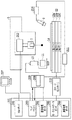
図1(a)は、本実施形態のインクジェット記録ヘッドの検査装置を上方から平面図、(b)は、それを側方から見た側面図である。
Embodiments of the present invention will be described below in detail with reference to the drawings.
(First embodiment)
FIG. 1A is a plan view from above of an ink jet recording head inspection apparatus according to the present embodiment, and FIG. 1B is a side view of the inspection apparatus viewed from the side.
本例の検査装置に対しては、この検査装置における検査工程の前の処理工程から、ベルトコンベア6によって検査対象のインクジェット記録ヘッド7が搬送される。検査装置は、4つのヘッド固定部1が90°の等間隔に設けられたロータリーインデックス5を備えている。ロータリーインデックス5が図1(b)中の軸線Oを中心として図1(a)中の右回りに90°ずつ回転することにより、4つのヘッド固定部1が搬入/搬出部13、吸引回復部2、画像記録部3、および秤量部4の位置に順次移動する。ベルトコンベア6によって搬送される記録ヘッド7は、搬入/搬出部13に位置するヘッド固定部1に挿入されて、クランプ治具8によって固定される。そのヘッド固定部1に固定された記録ヘッド7は、ロータリーインデックス5が右回りに90°回転することにより吸引回復部2に移動し、この吸引回復部2において、記録ヘッド7の吐出口から記録ヘッド内のインクを吸引する吸引回復が行われる。
For the inspection apparatus of this example, the
その後、そのヘッド固定部1の記録ヘッド7は、ロータリーインデックス5がさらに右回りに90°回転することにより画像記録部3に移動し、その画像記録部3において、吐出口からXYZステージ12上の記録媒体にインクを吐出して検査画像を記録する。その記録された検査画像は、レンズ鏡筒ユニット11を通してCCDカメラ(読み取り部)10によって読み取られてから、画像処理および演算処理されることによって、検査画像の記録状態つまり記録ヘッド7のインクの吐出状態が検査される。検査画像は、LED(照明部)9などによって照明される。
Thereafter, the
その後、そのヘッド固定部1に固定された記録ヘッド7は、ロータリーインデックス5がさらに右回りに90°回転することにより秤量部4に移動し、その秤量部4において秤量される。その後、そのヘッド固定部1に固定された記録ヘッド7は、ロータリーインデックス5がさらに右回りに90°回転することにより搬入/搬出部13に移動し、その搬入/搬出部13において、ベルトコンベア6上に戻されて次の処理工程へ搬送される。その記録ヘッド7に代わって、新たな検査対象の記録ヘッド7がヘッド固定部1に固定される。
Thereafter, the
このように本例の検査装置においては、ロータリーインデックス5の90°ずつの回転に伴って、記録ヘッド7のインクの吐出状態が連続的に検査される。
As described above, in the inspection apparatus of this example, the ink ejection state of the
図2は、画像記録部3の概略構成図である。
FIG. 2 is a schematic configuration diagram of the
この画像記録部3において、ロータリーインデックス5のヘッド固定部1に固定されている記録ヘッド7は、信号変換基板212に接続される。記録ヘッド7に対しては、パーソナルコンピュータ(制御装置)201内のヘッドドライバ203によって生成されたインク吐出用の駆動信号が送信される。また、インクの吐出タイミングに同期した信号がステージコントローラ210を通してXYZステージ12に送られ、そのステージ12の移動と同期して記録ヘッド7が吐出口からインクを吐出する。これにより、XYZステージ12上の記録媒体14に検査パターンが記録される。その検査画像は、レンズ鏡筒ユニット11を通してカメラ10に読み込まれる。カメラ10には、同期基板208およびカメラ電源209が接続されている。
In the
カメラ10によって読み込まれた検査画像は、PC201内の画像処理ボード204において、背景ノイズが除去され後、インクの主滴によって形成される主ドットが抽出されてから、2値化処理されることによって主ドットの重心点が算出される。複数の主ドットの重心点から最小二乗法により仮想格子を作成して、その格子点(理想的な格子点)からの主ドットのずれ量を計測し、その計測結果から記録ヘッド7のインクの吐出状態の良否を判定する。理想的な格子点は、複数の吐出口から吐出されるインクによって形成される複数のドットの位置がx方向およびy方向において一定となる条件において、複数のドットの位置の誤差が最小となるように最小二乗法により設定する。このような演算処理は、PC201内の演算処理ボード206において行う。このときの処理画像は、逐次、VGAボード202を通してモニタ207に出力される。記録ヘッド7とカメラ10との絶対位置は、予め、モータコントローラボード205がステージコントローラ210を通してXYZステージ12を制御することによって調整する。XYZステージ12は、X軸ステージ12A、Y軸ステージ12B、およびZ軸ステージ12Cを組み合わせた構成となっている。LED(照明部)9には、光源ユニット216とLED用電源211が接続されている。
The inspection image read by the
図3(a)は、記録ヘッド7の構成例を吐出口側から見た斜視図、(b)は、それをインクタンク側から見た斜視図である。本例の記録ヘッド7には、フライングリ−ドを有する電気配線部材305が備えられている。
3A is a perspective view of the configuration example of the
記録ヘッド7におけるインクの吐出方式としては、ピエゾ素子等の電気機械変換素子を用いる方式、および電気熱変換素子(ヒータ)によってインクを発泡させ、その発泡エネルギーを利用してインク滴を吐出させ方式がある。また、レーザー等の電磁波を照射してインクを発熱させ、この熱を利用してインクを吐出させる方式などもある。また、記録ヘッド7としては、インクタンクが着脱可能なタンク交換形態のもの、およびインクタンクと一体となった形態のものなどがある。
As an ink ejection method in the
本例の記録ヘッド7は、インクタンクと一体の形態であって、電気熱変換素子を用いてインクを吐出する構成となっている。また、その記録ヘッド7は、電気熱変換素子とインクの吐出口とがインクの吐出方向において対向する、いわゆるサイドシュータ型のインクジェット記録ヘッドである。記録ヘッド7は、吐出エネルギー発生素子としての電気熱変換素子(以下、「ヒータ」ともいう)を有する基板303、フライングリ−ドを有する電気配線部材305、インク供給保持部材306、蓋部材309、および電気接点301などによって構成されている。また、記録ヘッド7には、記録装置における記録ヘッド装着部に係合可能な係合部302が設けられている。
The
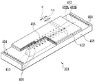
基板303は、図4のように、Si基材405にインク供給口410を形成した構成となっている。基材405には、インク供給口410の両側にヒータ408が1列ずつ配置されており、さらにヒータ408に電力を供給するための電気配線が形成されている。それぞれ列のヒータ408は、互いに千鳥状になるように配列されている。インク供給口410から供給されたインクは、ヒータ408の発熱によって発泡され、そのときの圧力を利用して、ヒータ408と対向する吐出口406から吐出される。吐出口406は、ヒータ408の列と対応する吐出口列402(402A,402B)を成すように、天板412に形成されている。
As shown in FIG. 4, the
吐出口406は、図5のようにヒータ408と同様に配列されている。すなわち、吐出口406は、吐出口列402A,402Bのそれぞれにおいて所定のピッチPで配列され、かつ吐出口列402Aの吐出口406と、吐出口列402Bの吐出口406と、は半ピッチ(P/2)ずらされている。吐出口列402Aは、記録ヘッド7の偶数セグメント(0seg〜318seg)が配列された偶数列であり、吐出口列402Bは、記録ヘッド7の偶数セグメント(1seg〜319seg)が配列された偶数列である。本例の場合、ピッチPは300dpiの記録解像度に対応し、半ピッチ(P/2)は600dpiの記録解像度に対応する。
The
図3(a)において、電気配線部材305は、基材405にインク吐出用の電気信号を導くための電気信号経路を形成する。電気配線部材305には、基板303を組み込むための開口部が形成されており、この開口部の縁付近に、基板303の電気接続端子部に接続されるフライングリード部が形成されている。さらに、電気配線部材305には、記録装置から電気信号を受け取るための電気接点301として外部信号入力端子が形成されており、この外部信号入力端子とフライングリード部とが配線パターンによって接続されている。
In FIG. 3A, the
インク供給保持部材306は、その内部に、インクを保持して負圧を発生するための吸収体を有することにより、インクタンクとしての機能をもっている。インク供給保持部材306内のインクは、基材405のインク供給口410を通して、基材405と天板412との間に供給される。基材405には、電気配線部材305の一部の裏面が接着固定される。基材405のコンタクトパッド404と電気配線部材305との電気接続部分は、封止剤により封止されている。蓋部材309は、インク供給保持部材306の上部開口部に溶着されることにより、インク供給保持部材306の内部を密閉する。蓋部材309には、インク供給保持部材306の内部の圧力を外部に逃がすために、細口と、それに連通した微細溝と、によって、大気連通路が形成されている。
The ink
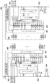
図6は、記録ヘッド7の基体601における回路構成の説明図である。
FIG. 6 is an explanatory diagram of a circuit configuration in the
基体601上において、ラッチ回路602は、入力端子604から入力するラッチ信号に基づいて、インクジェット記録装置の制御部から入力される記録データをラッチする。シフトレジスタ603は、シフトクロックに同期して、記録データをシリアルに入力して保持する。ヒータ408を駆動するためのヒートパルス信号は、入力端子605から入力される。シフトレジスタ603は、ヒータ408の駆動条件を選択するためにROMに記憶さていれる選択データをシリアルに入力して保持し、ラッチ回路602は、その選択データをラッチする。ヒータ408毎のAND回路606は、ヒートパルス信号と、記録データ信号と、ブロック信号と、選択データと、の論理和をとる。AND回路606の出力がハイレベルになると、それに対応するトランジスタアレイ607内のヒータ駆動用のトランジスタがオンとなり、そのトランジスタに接続されているヒータ408に電流が流されて、それが発熱駆動される。
On the
次に、このような記録ヘッド7の動作について説明する。
まず、電源の投入後に、予め測定されている基体601毎のインク発泡水準に応じて、ヒータ408毎に印加されるヒートパルス(プレヒートパルスとメインヒートパルスを含む)のパルス幅を決定する。インク発泡水準は、一定の温度条件下において、ヒータ408に所定の電圧のヒートパルスを印加したときに、インクを吐出可能な最小のパルス値をランク分けしたものである。これらのヒートパルスの幅データは、シフトクロックに同期してシフトレジスタ603に転送されて、ヒータ408に印加する電圧信号が生成される。ヒータ408の駆動条件を選択するためにROMに記憶されている選択データは、ラッチ回路602にラッチされる。そのラッチは、例えば、記録ヘッド7の起動時等に一度だけ行えばよい。ROMからの信号によって選択されたパルスデータに応じて、インクの吐出に適正なエネルギーをヒータ408に印加するように、ヒートパルスのパルス幅が決定される。また、記録ヘッド7の温度を検出する温度センサ609(ダイオードセンサ)の検出値に応じて、プレヒートパルスのパルス幅、その印加タイミングが決定される。種々の温度条件下においても各吐出口からのインクの吐出量が一定となるように、種々のヒートパルス(メインヒートパルスとプレヒートパルスを含む)を設定することができる。
Next, the operation of such a
First, after the power is turned on, the pulse width of the heat pulse (including the preheat pulse and the main heat pulse) applied to each
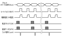
図7は、記録ヘッド7の駆動タイミングの説明図である。記録ヘッドは、ヒータ408を複数のブロック(群)に分けて、それらをブロック毎に時分割駆動する。
FIG. 7 is an explanatory diagram of the drive timing of the
シフトレジスタ603は、入力端子から供給される転送クロック(CLK)に基づいて、入力端子からシリアルに供給される記録データ(DATA)を入力し、その記録データをラッチ回路602にパラレルに出力する。ラッチ回路602は、ラッチ信号(Latch)に基づいて記録データを保持する。ヒータ408(本例の場合は、320個のヒータ)は複数のブロック(群)に分割され、入力端子から供給されるブロックイネーブル信号(Block)に基づいて、駆動対象のブロックが選択される。AND回路606は、記録データに応じて出力されるヒートパルス(HEAT)と、ブロックイネーブル信号に基づいて選択されて出力される信号と、の論理和をとって、トランジスタアレイ607内のヒータ駆動用のトランジスタをオンとする信号を出力する。ヒータ駆動用トランジスタがオンとなることにより、それに接続されているヒータ408に駆動電流(VH電流)が流れて、それが発熱駆動される。
The
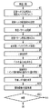
図8は、図1の検査装置における検査工程を説明するためのフローチャートである。 FIG. 8 is a flowchart for explaining an inspection process in the inspection apparatus of FIG.
まず、検査装置のヘッド固定部1に対する記録ヘッド7の位置決め、および、その記録ヘッド7と検査装置との電気的な接続をチェックする(ステップS1)。
First, the positioning of the
次に、インク滴の着弾位置の測定用の検査パターンを記録するために記録ヘッド7の駆動条件を設定する(ステップS2)。具体的には、ヒータ408の抵抗値を測定して、その抵抗値に基づいて、記録ヘッド7からインクを吐出するためにヒータ408に印加する吐出エネルギーの量(駆動パルスのパルス幅)を設定する。さらに、ヒータ408に印加する駆動パルスの電圧(例えば、24.0V)を設定し、ステージ12上の記録媒体(紙など)を記録ヘッド7と対向させるように、ステージ12を移動させる。
Next, the drive condition of the
その後、ステージ12上の記録媒体に検査パターンを記録する(ステップS3)。その際には、ステージ12を所定の速度で移動させつつ、先に設定した駆動条件に基づいて記録ヘッド7からインクを吐出する。ステージ12の移動速度は、記録ヘッド7のインクの吐出特性により決定され、本例の場合は、25inch/secである。
Thereafter, the inspection pattern is recorded on the recording medium on the stage 12 (step S3). At that time, while moving the
図9(a)は、ステージ12上の記録媒体14に記録した検査パターンの全体図であり、(b)は、その検査パターンの一部の拡大図である。記録媒体14を矢印Y方向に移動させつつ、記録ヘッド7をブロック毎に時分割駆動して、4つのセグメントおきに同一の吐出タイミングTa,Tb,Tc,Tdでインクを吐出することによって、検査パターンを記録する。
FIG. 9A is an overall view of an inspection pattern recorded on the
次に、記録した検査パターンの画像データを読み込む(ステップS4)。すなわち、検査パターンが記録された記録媒体14をカメラ10の測定エリアに位置させるように、ステージ12を移動させる。そして、カメラ10の画像の読み込み特性により決定される速度でステージ12を移動させつつ、カメラ10によって、検査パターンを読み込む。本例の場合、ステージ12の移動速度は、検査パターンの記録時と同様の25inch/secとした。
Next, the image data of the recorded inspection pattern is read (step S4). That is, the
検査パターンの画像データは、背景ノイズの除去およびシェーディング補正などの前処理(バックグラウンド処理)をしてから、2値化処理をする(ステップS5,S6)。その後、記録媒体14に着弾したインク滴によって形成されるドットの重心点を求め(ステップS7)、その重心点のXY座標から、理想的な着弾点としての理想格子点を最小二乗法により求める。その理想格子点と、それに近接するドットの重心のXY座標と、の位置関係から、それぞれのドットを形成するインク滴の着弾位置のずれ量を取得する(ステップS8)。
The image data of the inspection pattern is subjected to preprocessing (background processing) such as background noise removal and shading correction, and then binarized (steps S5 and S6). Thereafter, the barycentric point of the dot formed by the ink droplet landed on the
図10は、インク滴の着弾位置のずれ量の例の説明図である。記録ヘッド7のnセグメントに関しては、それから吐出されるインク滴によって形成されるドットD1の重心点と、それに対応する理想格子点と、の間におけるX方向の距離XnμmおよびY方向の距離Ynμmが着弾位置のX方向およびY方向のずれ量となる。他のセグメント(n+1セグメント、n+6セグメント、n+7セグメントから吐出されるドットDn+1、ドットDn+6、ドットDn+7についても同様である。
FIG. 10 is an explanatory diagram of an example of the deviation amount of the landing position of the ink droplet. Regarding the n segment of the
図11は、それぞれのセグメント毎の着弾位置のY方向のずれ量をグラフ化した図である。全セグメント(1セグメント〜192セグメント)の着弾位置のY方向のずれ量の標準偏差値(σ)は7.70となり、これは、規格上のNGレベルの数値である。本発明者の観察により、カメラによって読み込まれる検査パターンの画像は、それを読み込む際の装置(検査装置および他の周辺装置を含む)の振動の影響を受けていることがレーザー変位計での計測により分かった。図11の例の場合には、第3番目のインクの吐出タイミングTcにおいて、振動が大きく影響している。つまり、時間によって変化する振動は、吐出タイミングTcにおいて大きな影響を及ぼすように生じている。 FIG. 11 is a graph of the amount of deviation in the Y direction of the landing position for each segment. The standard deviation value (σ) of the deviation amount in the Y direction of the landing positions of all segments (1 segment to 192 segments) is 7.70, which is a numerical value at the NG level in the standard. According to the observation of the present inventor, it is measured with a laser displacement meter that the image of the inspection pattern read by the camera is affected by the vibration of the device (including the inspection device and other peripheral devices) when reading the image. I understood. In the case of the example in FIG. 11, the vibration has a great influence on the third ink ejection timing Tc. That is, the vibration that changes with time is generated so as to have a great influence on the discharge timing Tc.
図12は、図11の着弾位置のY方向のずれ量を図9の吐出タイミングTa,Tb,Tc,Td毎に分けてグラフ化した図である。すなわち、インクの吐出タイミングがTaのセグメントを第1群、インクの吐出タイミングがTbのセグメントを第2群、インクの吐出タイミングがTcのセグメントを第3群、インクの吐出タイミングがTdのセグメントを第4群とした。図12には、それらのセグメントの群別に着弾位置のY方向のずれ量の特徴が明確に現れ、特に、振動の影響を受けた第3群のセグメントにおける着弾位置のずれ量が大きくなっている。 FIG. 12 is a graph in which the amount of deviation in the Y direction of the landing position in FIG. 11 is divided into the discharge timings Ta, Tb, Tc, and Td in FIG. That is, the segment whose ink discharge timing is Ta is the first group, the segment whose ink discharge timing is Tb is the second group, the segment whose ink discharge timing is Tc is the third group, and the segment whose ink discharge timing is Td is The fourth group. FIG. 12 clearly shows the characteristics of the deviation amount in the Y direction of the landing position for each group of the segments, and in particular, the deviation amount of the landing position in the third group segment affected by the vibration is large. .
本実施形態においては、このようなセグメントの群毎(グループ毎)の着弾位置のY方向のずれ量の特徴を利用して、そのずれ量を補正し、その後、全てセグメントについて着弾位置のY方向のずれ量σを算出する。すなわち、図12のように、セグメントを吐出タイミング毎の群に分けて、それらの群毎に着弾位置のY方向のずれ量を算出する。そして、それらの群毎の着弾位置のY方向のずれ量と、全てのセグメントの着弾位置のY方向のずれ量の平均値と、の差が0となるように、図8のステップS9において、着弾位置のY方向のずれ量を群毎に補正する。 In the present embodiment, the deviation amount in the Y direction of the landing position of each segment group (for each group) is corrected using the feature of the deviation amount in the Y direction, and then the Y direction of the landing position for all the segments. Is calculated. That is, as shown in FIG. 12, the segments are divided into groups for each ejection timing, and the deviation amount in the Y direction of the landing position is calculated for each group. Then, in step S9 of FIG. 8, the difference between the amount of deviation in the Y direction of the landing position for each group and the average value of the amount of deviation in the Y direction of the landing positions of all the segments becomes zero. The amount of deviation of the landing position in the Y direction is corrected for each group.
図13は、着弾位置のY方向のずれ量の平均値を求めるための演算式を示す。 FIG. 13 shows an arithmetic expression for obtaining the average value of the deviation amounts of the landing positions in the Y direction.
式(1)は、全てのセグメントについての着弾位置のY方向のずれ量の平均値を求めるための演算式、式(2)は、第1群のセグメントについての着弾位置のY方向のずれ量の平均値Yaを求めるための演算式である。同様に、式(3)は第2群のセグメントについての平均値Yb、式(4)は第3群のセグメントについての平均値Yc、式(5)は第4群のセグメントについての平均値Ydを求めるための演算式である。式(6)は、第1群のセグメントについての補正後の着弾位置のY方向のずれ量y′4iの演算式(i=0,1,2,・・・,48)である。同様に、式(7)は第2群のセグメントについての補正後のずれ量y′4i+1、式(8)は第3群のセグメントについての補正後のずれ量y′4i+2、式(9)は第4群のセグメントについての補正後のずれ量y′4i+3の演算式である。図15は、補正後のY方向のずれ量を第1,第2,第3,および第4群に分けてグラフ化した図であり、図16は、補正後のY方向のずれ量をセグメントの並び順にしたがってグラフ化した図である。 Expression (1) is an arithmetic expression for obtaining the average value of the deviation amounts in the Y direction of the landing positions for all segments, and Expression (2) is the deviation amount of the landing positions in the Y direction for the first group of segments. Is an arithmetic expression for obtaining the average value Ya. Similarly, Equation (3) is the average value Yb for the second group segment, Equation (4) is the average value Yc for the third group segment, and Equation (5) is the average value Yd for the fourth group segment. Is an arithmetic expression for obtaining. Expression (6) is an arithmetic expression (i = 0, 1, 2,..., 48) for the Y-direction deviation amount y ′ 4i of the landing position after correction for the first group of segments. Similarly, the equation (7) is the corrected shift amount y ′ 4i + 1 for the second group segment, the equation (8) is the corrected shift amount y ′ 4i + 2 for the third group segment, and the equation (9) is It is a calculation formula of the corrected shift amount y ′ 4i + 3 for the fourth group of segments. FIG. 15 is a graph showing the corrected amount of deviation in the Y direction divided into the first, second, third, and fourth groups, and FIG. 16 shows the corrected amount of deviation in the Y direction as a segment. FIG.
その後、図8のステップS10において、補正前と補正後におけるY方向のずれ量の標準偏差を演算する。図14において、式(11)は、補正前のY方向のずれ量の標準偏差(σy)の演算式であり、式(12)は、補正後のY方向のずれ量の標準偏差(σy′)の演算式である。 Thereafter, in step S10 of FIG. 8, the standard deviation of the deviation amount in the Y direction before and after the correction is calculated. In FIG. 14, equation (11) is an arithmetic expression for the standard deviation (σy) of the deviation amount in the Y direction before correction, and equation (12) is the standard deviation (σy ′) of the deviation amount in the Y direction after correction. ).
前述したように、振動の影響を受けた補正前のY方向のずれ量の標準偏差(σy)は7.70であり、これに対して、補正後のY方向のずれ量の標準偏差(σy′)は2.10となった。補正後のY方向のずれ量は、振動の影響を除去した後の記録ヘッドの本来のY方向のずれ量に近似される。したがって、このような補正後のY方向のずれ量の標準偏差と、基準の標準偏差と、の比較結果に基づいて、より正確に記録ヘッドのインクの吐出性能を検査して、図8のステップS11において、その良否をより確実に判定することができる。 As described above, the standard deviation (σy) of the deviation amount in the Y direction before correction affected by the vibration is 7.70, whereas the standard deviation (σy) of the deviation amount in the Y direction after correction is ') Became 2.10. The corrected amount of deviation in the Y direction is approximated to the original amount of deviation in the Y direction of the recording head after the influence of vibration is removed. Accordingly, the ink ejection performance of the recording head is more accurately inspected based on the comparison result between the standard deviation of the deviation amount in the Y direction after correction and the standard deviation of the reference, and the step of FIG. In S11, the quality can be determined more reliably.
このように本実施形態においては、インクの吐出タイミングが異なる複数の群に分けたセグメントからインクを吐出して検査パターンを記録し、それらの群毎に、ドットの形成位置に対応するインクの着弾位置を補正する。これにより、時間により変化する振動が検査パターンの記録および読み取りに及ぼす影響を小さく抑えて、インクの着弾位置をより正確に検知して、記録ヘッドの良否をより確実に判定することができる。また、特別な装置や機構を用いることなく、正確かつ安価に記録ヘッドの検査を行うことができる。 As described above, in this embodiment, ink is ejected from the segments divided into a plurality of groups having different ink ejection timings, and the test pattern is recorded, and ink landing corresponding to the dot formation position is performed for each group. Correct the position. Accordingly, it is possible to suppress the influence of the vibration changing with time on recording and reading of the inspection pattern, to detect the ink landing position more accurately, and to more reliably determine the quality of the recording head. Further, the recording head can be inspected accurately and inexpensively without using a special device or mechanism.
(第2の実施形態)
本実施形態の場合は、前述した実施形態の標準偏差の演算処理(ステップS10)において、補正後のY方向のずれ量の標準偏差として、第1,第2,第3,および第4群毎に関する標準偏差を算出する。図17において、式(21)は、第1群のセグメントに関する標準偏差(σy′a)を算出するための演算式であり、式(22)は、第2群のセグメントに関する標準偏差(σy′b)を算出するための演算式である。同様に、式(23)は、第3群のセグメントに関する標準偏差(σy′c)、式(24)は、第4群のセグメントに関する標準偏差(σy′d)を算出するための演算式である。前述した例においては、第1群の標準偏差は2.23、第2群の標準偏差は2.17、第3群の標準偏差は1.74、第4群の標準偏差は2.28となる。さらに、図17の式(25)によって、第1群から第4群までの標準偏差の二乗平均値は2.12となる。この値を記録ヘッドのY方向のずれ量の標準偏差(σy′)とする。
(Second Embodiment)
In the case of this embodiment, in the standard deviation calculation process (step S10) of the above-described embodiment, as the standard deviation of the deviation amount in the Y direction after correction, for each of the first, second, third, and fourth groups. Calculate the standard deviation for. In FIG. 17, Expression (21) is an arithmetic expression for calculating the standard deviation (σy′a) for the first group of segments, and Expression (22) is the standard deviation (σy ′ for the second group of segments). It is an arithmetic expression for calculating b). Similarly, Expression (23) is an arithmetic expression for calculating the standard deviation (σy′c) for the third group segment, and Expression (24) is an arithmetic expression for calculating the standard deviation (σy′d) for the fourth group segment. is there. In the above-described example, the standard deviation of the first group is 2.23, the standard deviation of the second group is 2.17, the standard deviation of the third group is 1.74, and the standard deviation of the fourth group is 2.28. Become. Furthermore, according to the equation (25) in FIG. 17, the root mean square value of the standard deviation from the first group to the fourth group is 2.12. This value is taken as the standard deviation (σy ′) of the deviation amount of the recording head in the Y direction.
前述したように、振動の影響を受けた補正前のY方向のずれ量の標準偏差(σy)は7.70であり、これに対して、補正後のY方向のずれ量の標準偏差(σy′)は2.12となった。補正後のY方向のずれ量は、振動の影響を除去した後の記録ヘッドの本来のY方向のずれ量に近似される。したがって、このような補正後のY方向のずれ量に基づいて、より正確に記録ヘッドのインクの吐出性能を検査して、その良否をより確実に判定することができる。 As described above, the standard deviation (σy) of the deviation amount in the Y direction before correction affected by the vibration is 7.70, whereas the standard deviation (σy) of the deviation amount in the Y direction after correction is ') Became 2.12. The corrected amount of deviation in the Y direction is approximated to the original amount of deviation in the Y direction of the recording head after the influence of vibration is removed. Therefore, it is possible to more accurately determine the quality by inspecting the ink ejection performance of the recording head more accurately based on the corrected amount of deviation in the Y direction.
(第3の実施形態)
本実施形態においては、群毎のセグメントに関するY方向のずれ量の平均値を算出する。そして、それらの平均値の絶対値が5μmより大きい場合は、全てのセグメントのY方向のずれ量の平均値と、群毎のセグメントに関するY方向のずれ量の平均値と、の差が0となるように補正する。前述した図11および図12のようにインクの着弾位置がY方向にずれた場合、第3群のセグメントに関するずれ量の平均値は、11.81μmとなり、第4群のセグメントに関するずれ量の平均値は、−7.91μmとなる。この場合には、これらの群のずれ量の平均値が全セグメントのずれ量の平均値との差が0となるように補正する。
(Third embodiment)
In the present embodiment, the average value of the deviation amounts in the Y direction related to the segments for each group is calculated. And when the absolute value of those average values is larger than 5 micrometers, the difference of the average value of the deviation amount of the Y direction of all the segments and the average value of the deviation amount of the Y direction regarding the segment for every group is 0. Correct so that When the ink landing position is shifted in the Y direction as shown in FIG. 11 and FIG. 12, the average value of the shift amount related to the third group segment is 11.81 μm, and the average shift amount related to the fourth group segment is The value is −7.91 μm. In this case, correction is performed so that the difference between the average value of the deviation amounts of these groups and the average value of the deviation amounts of all the segments becomes zero.
図18は、補正後のY方向のずれ量を第1,第2,第3,および第4群に分けてプロットした図である。このようにずれ量を補正することにより、補正後のずれ量の標準偏差は2.71となった。 FIG. 18 is a diagram in which the corrected deviation amount in the Y direction is plotted separately for the first, second, third, and fourth groups. By correcting the shift amount in this way, the standard deviation of the corrected shift amount is 2.71.
前述したように、振動の影響を受けた補正前のY方向のずれ量の標準偏差(σy)は7.70であり、これに対して、補正後のY方向のずれ量の標準偏差(σy′)は2.71となった。補正後のY方向のずれ量は、振動の影響を除去した後の記録ヘッドの本来のY方向のずれ量に近似される。したがって、このような補正後のY方向のずれ量に基づいて、より正確に記録ヘッドのインクの吐出性能を検査して、その良否をより確実に判定することができる。 As described above, the standard deviation (σy) of the deviation amount in the Y direction before correction affected by the vibration is 7.70, whereas the standard deviation (σy) of the deviation amount in the Y direction after correction is ') Became 2.71. The corrected amount of deviation in the Y direction is approximated to the original amount of deviation in the Y direction of the recording head after the influence of vibration is removed. Therefore, it is possible to more accurately determine the quality by inspecting the ink ejection performance of the recording head more accurately based on the corrected amount of deviation in the Y direction.
(他の実施形態)
検査パターンの記録時は、記録ヘッドに対して記録媒体を移動させてもよい。また、本発明は、インクを吐出可能なインクジェット記録ヘッドの他、インク以外の種々の液体を吐出可能な液体吐出ヘッドの検査装置および検査装置としても広く適用することができる。
(Other embodiments)
When recording the inspection pattern, the recording medium may be moved with respect to the recording head. The present invention can also be widely applied as an inspection apparatus and an inspection apparatus for a liquid ejection head capable of ejecting various liquids other than ink, in addition to an ink jet recording head capable of ejecting ink.
1 ロータリーインデックス
7 記録ヘッド
10 カメラ(読み取り部)
12 ステージ
14 記録媒体
201 パーソナルコンピュータ(制御装置)
406 吐出口
1
12
406 Discharge port
Claims (7)
前記複数の吐出口を複数のブロックに分けて、前記複数の吐出口からのインクの吐出タイミングを前記ブロック毎にずらすように前記インクジェット記録ヘッドを時分割駆動することにより、記録媒体に、前記複数のブロックのそれぞれに属する前記吐出口によって所定の検査パターンを記録する制御手段と、
前記記録媒体に記録された前記検査パターンを読み取る読み取り手段と、
前記読み取り手段によって読み取った前記検査パターンの画像データを画像処理して、前記吐出口から吐出されるインクによって前記記録媒体に形成されるドットの位置ずれ量を取得する取得手段と、
前記取得手段により取得した前記ドットの位置ずれ量に基づいて前記ブロック毎に設定される補正量に応じて、前記取得手段により取得された前記ドットの位置ずれ量を前記ブロック毎に補正する補正手段であって、前記ブロック毎の補正量は、それに対応するブロックに属する前記吐出口から吐出されるインクによって形成される前記ドットの位置ずれ量に基づいて、前記ブロック毎に個別に設定される、補正手段と、
前記取得手段により取得されかつ前記補正手段によって前記ブロック毎に補正された前記ドットの位置ずれ量に基づいて、前記インクジェット記録ヘッドにおけるインクの吐出性能を検査する検査手段と、
を備えることを特徴とするインクジェット記録ヘッドの検査装置。 An inspection apparatus for an ink jet recording head capable of discharging ink from a plurality of discharge ports forming a discharge port array,
The plurality of ejection openings are divided into a plurality of blocks, and the inkjet recording head is driven in a time-sharing manner so that the ejection timing of ink from the plurality of ejection openings is shifted for each block. Control means for recording a predetermined inspection pattern by the discharge ports belonging to each of the blocks;
Reading means for reading the inspection pattern recorded on the recording medium;
Acquisition means for performing image processing on the image data of the inspection pattern read by the reading means, and acquiring a positional deviation amount of dots formed on the recording medium by ink discharged from the discharge ports;
A correction unit that corrects the dot displacement amount acquired by the acquisition unit for each block according to a correction amount set for each block based on the dot displacement amount acquired by the acquisition unit. The correction amount for each block is individually set for each block based on the positional deviation amount of the dots formed by the ink ejected from the ejection ports belonging to the corresponding block. Correction means;
Inspection means for inspecting the ink ejection performance of the ink jet recording head based on the positional deviation amount of the dots acquired by the acquisition means and corrected for each block by the correction means;
An inspection apparatus for an ink jet recording head, comprising:
前記理想的な格子点は、前記複数の吐出口から吐出されるインクによって形成される複数のドットの位置がx方向およびy方向において一定となる条件において、前記複数のドットの位置の誤差が最小となるように最小二乗法により設定した点である
ことを特徴とする請求項1に記載のインクジェット記録ヘッドの検査装置。 The acquisition means acquires the positional deviation amount of the dot from the positional relationship between the barycentric point of the recorded dot and an ideal lattice point,
The ideal lattice point has a minimum error in the positions of the plurality of dots under the condition that the positions of the plurality of dots formed by the ink ejected from the plurality of ejection openings are constant in the x direction and the y direction. The inkjet recording head inspection apparatus according to claim 1, wherein the inspection point is set by a method of least squares such that
前記複数の吐出口を複数のブロックに分けて、前記複数の吐出口からのインクの吐出タイミングを前記ブロック毎にずらすように前記インクジェット記録ヘッドを時分割駆動することにより、記録媒体に、前記複数のブロックのそれぞれに属する前記吐出口によって所定の検査パターンを記録する記録工程と、
前記記録媒体に記録された前記検査パターンを読み取る読み取り工程と、
前記読み取り工程によって読み取った前記検査パターンの画像データを画像処理して、前記吐出口から吐出されるインクによって前記記録媒体に形成されるドットの位置ずれ量を取得する取得工程と、
前記取得工程により取得した前記ドットの位置ずれ量に基づいて前記ブロック毎に設定される補正量に応じて、前記取得工程により取得された前記ドットの位置ずれ量を前記ブロック毎に補正する補正工程であって、前記ブロック毎の補正量は、それに対応するブロックに属する前記吐出口から吐出されるインクによって形成される前記ドットの位置ずれ量に基づいて、前記ブロック毎に個別に設定される、補正工程と、
前記取得工程により取得されかつ前記補正工程によって前記ブロック毎に補正された前記ドットの位置ずれ量に基づいて、前記インクジェット記録ヘッドにおけるインクの吐出性能を検査する検査工程と、
を含むことを特徴とするインクジェット記録ヘッドの検査方法。 An inspection method for an inkjet recording head capable of discharging ink from a plurality of discharge ports forming a discharge port array,
The plurality of ejection openings are divided into a plurality of blocks, and the inkjet recording head is driven in a time-sharing manner so that the ejection timing of ink from the plurality of ejection openings is shifted for each block. A recording step of recording a predetermined inspection pattern by the discharge ports belonging to each of the blocks;
A reading step of reading the inspection pattern recorded on the recording medium;
And image processing the image data of the test pattern read by said reading step, an acquisition step of acquiring positional shift amount of dots formed on the recording medium by ink ejected from the ejection port,
In accordance with the correction amount set for each of the blocks based on the positional deviation amount of the dot obtained by the obtaining step, correction step of correcting the positional deviation amount of the dot obtained by the obtaining step for each of the blocks The correction amount for each block is individually set for each block based on the positional deviation amount of the dots formed by the ink ejected from the ejection ports belonging to the corresponding block. A correction process;
An inspection step of inspecting ink ejection performance in the inkjet recording head based on the positional deviation amount of the dots acquired by the acquisition step and corrected for each block by the correction step;
A method for inspecting an ink jet recording head, comprising:
Priority Applications (2)
| Application Number | Priority Date | Filing Date | Title |
|---|---|---|---|
| JP2013260499A JP6497842B2 (en) | 2013-12-17 | 2013-12-17 | Inkjet recording head inspection apparatus and inspection method |
| US14/564,360 US9701130B2 (en) | 2013-12-17 | 2014-12-09 | Apparatus and method for inspecting inkjet print head |
Applications Claiming Priority (1)
| Application Number | Priority Date | Filing Date | Title |
|---|---|---|---|
| JP2013260499A JP6497842B2 (en) | 2013-12-17 | 2013-12-17 | Inkjet recording head inspection apparatus and inspection method |
Publications (3)
| Publication Number | Publication Date |
|---|---|
| JP2015116701A JP2015116701A (en) | 2015-06-25 |
| JP2015116701A5 JP2015116701A5 (en) | 2017-01-12 |
| JP6497842B2 true JP6497842B2 (en) | 2019-04-10 |
Family
ID=53367378
Family Applications (1)
| Application Number | Title | Priority Date | Filing Date |
|---|---|---|---|
| JP2013260499A Active JP6497842B2 (en) | 2013-12-17 | 2013-12-17 | Inkjet recording head inspection apparatus and inspection method |
Country Status (2)
| Country | Link |
|---|---|
| US (1) | US9701130B2 (en) |
| JP (1) | JP6497842B2 (en) |
Families Citing this family (1)
| Publication number | Priority date | Publication date | Assignee | Title |
|---|---|---|---|---|
| WO2021206736A1 (en) * | 2020-04-10 | 2021-10-14 | Hewlett-Packard Development Company, L.P. | Fluid ejection device testing |
Family Cites Families (10)
| Publication number | Priority date | Publication date | Assignee | Title |
|---|---|---|---|---|
| ATE122967T1 (en) | 1990-02-02 | 1995-06-15 | Canon Kk | INKJET RECORDING HEAD AND INKJET RECORDING DEVICE COMPRISING THIS RECORDING HEAD. |
| US6149259A (en) * | 1991-04-26 | 2000-11-21 | Canon Kabushiki Kaisha | Ink jet recording apparatus and method capable of performing high-speed recording |
| JP2001105579A (en) * | 1999-10-05 | 2001-04-17 | Canon Inc | Recording system, and method for correcting output characteristics of recorder |
| US6588872B2 (en) * | 2001-04-06 | 2003-07-08 | Lexmark International, Inc. | Electronic skew adjustment in an ink jet printer |
| JP2006284406A (en) * | 2005-04-01 | 2006-10-19 | Seiko Epson Corp | Dot displacement detection method, dot displacement detection program, reference line acquisition method, dot displacement detection device, and droplet discharge device |
| JP2007021745A (en) * | 2005-07-12 | 2007-02-01 | Matsushita Electric Ind Co Ltd | Method for inspecting ink jet head, aging device and recorder |
| JP5074733B2 (en) * | 2005-09-30 | 2012-11-14 | キヤノン株式会社 | Recording device |
| JP2009006677A (en) * | 2007-06-29 | 2009-01-15 | Canon Inc | Recording apparatus |
| JP5072455B2 (en) * | 2007-06-29 | 2012-11-14 | キヤノン株式会社 | Recording device |
| JP2010143025A (en) * | 2008-12-17 | 2010-07-01 | Canon Inc | Method for inspecting inkjet recording head and apparatus for the same |
-
2013
- 2013-12-17 JP JP2013260499A patent/JP6497842B2/en active Active
-
2014
- 2014-12-09 US US14/564,360 patent/US9701130B2/en active Active
Also Published As
| Publication number | Publication date |
|---|---|
| US9701130B2 (en) | 2017-07-11 |
| US20150165803A1 (en) | 2015-06-18 |
| JP2015116701A (en) | 2015-06-25 |
Similar Documents
| Publication | Publication Date | Title |
|---|---|---|
| JP2007090886A (en) | Method and system for positioning inkjet droplet | |
| JP2007090888A (en) | Method and system for positioning inkjet droplet | |
| US20050005996A1 (en) | Liquid droplet ejection apparatus, method of ejecting liquid droplet, method of manufacturing electrooptic device, electrooptic device, electronic device, and substrate | |
| US20180257100A1 (en) | Workpiece processing apparatus, workpiece processing method, and computer storage medium | |
| JP2009022915A (en) | Liquid droplet ejection method and liquid droplet ejection apparatus | |
| US8136913B2 (en) | System and method for measuring drop position in an image of a test pattern on an image substrate | |
| JP2012158140A (en) | Liquid ejecting apparatus and method for manufacturing the same | |
| EP2226196A2 (en) | System and method for correcting stitch and roll error in a staggered full width array printhead assembly | |
| JP2004141758A (en) | Method of correcting dot position of droplet discharge device, alignment mask, droplet discharge method, electro-optical device and its production method, and an electronic equipment | |
| JP6497842B2 (en) | Inkjet recording head inspection apparatus and inspection method | |
| US20090147035A1 (en) | Inspective ejection method for fluid ejection apparatus and fluid ejection apparatus implementing the method | |
| JP2010143025A (en) | Method for inspecting inkjet recording head and apparatus for the same | |
| JP2008111695A (en) | Visual inspection method | |
| JP2010120215A (en) | Method of correcting ejection pattern data of liquid drop ejector, and liquid drop ejector | |
| US10005303B2 (en) | System for detecting inoperative inkjets in three-dimensional object printing using a profilometer and predetermined test pattern printing | |
| JP5495528B2 (en) | Inkjet recording apparatus and inkjet recording method | |
| JP6582873B2 (en) | Image forming apparatus, program, and method | |
| JP2011224874A (en) | Inspection method of inkjet recording head | |
| JP5732249B2 (en) | Mounting method of recording head of image recording apparatus | |
| JP2009255093A (en) | Droplet discharge method and droplet discharge apparatus | |
| JP2012035552A (en) | Printing method on three-dimensional object | |
| JP2009148958A (en) | Examination device and examining method of ink-jet recording head | |
| Kwon et al. | Real-time jet failure detection of inkjet heads with 1024 ejectors | |
| JP2022115239A (en) | Liquid discharge device, inspection method, and inspection program | |
| JP2014124918A (en) | Inspection method and inspection device for inkjet recording head |
Legal Events
| Date | Code | Title | Description |
|---|---|---|---|
| A521 | Written amendment |
Free format text: JAPANESE INTERMEDIATE CODE: A523 Effective date: 20161128 |
|
| A621 | Written request for application examination |
Free format text: JAPANESE INTERMEDIATE CODE: A621 Effective date: 20161128 |
|
| A131 | Notification of reasons for refusal |
Free format text: JAPANESE INTERMEDIATE CODE: A131 Effective date: 20170808 |
|
| A977 | Report on retrieval |
Free format text: JAPANESE INTERMEDIATE CODE: A971007 Effective date: 20170809 |
|
| A521 | Written amendment |
Free format text: JAPANESE INTERMEDIATE CODE: A523 Effective date: 20171004 |
|
| A131 | Notification of reasons for refusal |
Free format text: JAPANESE INTERMEDIATE CODE: A131 Effective date: 20180206 |
|
| A521 | Written amendment |
Free format text: JAPANESE INTERMEDIATE CODE: A523 Effective date: 20180409 |
|
| A131 | Notification of reasons for refusal |
Free format text: JAPANESE INTERMEDIATE CODE: A131 Effective date: 20180911 |
|
| A521 | Written amendment |
Free format text: JAPANESE INTERMEDIATE CODE: A523 Effective date: 20181025 |
|
| TRDD | Decision of grant or rejection written | ||
| A01 | Written decision to grant a patent or to grant a registration (utility model) |
Free format text: JAPANESE INTERMEDIATE CODE: A01 Effective date: 20190212 |
|
| A61 | First payment of annual fees (during grant procedure) |
Free format text: JAPANESE INTERMEDIATE CODE: A61 Effective date: 20190312 |
|
| R151 | Written notification of patent or utility model registration |
Ref document number: 6497842 Country of ref document: JP Free format text: JAPANESE INTERMEDIATE CODE: R151 |