JP6496403B2 - A processing system configured to cooperate with an optical shape sensitive interventional device - Google Patents
A processing system configured to cooperate with an optical shape sensitive interventional device Download PDFInfo
- Publication number
- JP6496403B2 JP6496403B2 JP2017512954A JP2017512954A JP6496403B2 JP 6496403 B2 JP6496403 B2 JP 6496403B2 JP 2017512954 A JP2017512954 A JP 2017512954A JP 2017512954 A JP2017512954 A JP 2017512954A JP 6496403 B2 JP6496403 B2 JP 6496403B2
- Authority
- JP
- Japan
- Prior art keywords
- processing system
- virtual
- interventional device
- region
- shape
- Prior art date
- Legal status (The legal status is an assumption and is not a legal conclusion. Google has not performed a legal analysis and makes no representation as to the accuracy of the status listed.)
- Active
Links
- 238000012545 processing Methods 0.000 title claims description 63
- 230000003287 optical effect Effects 0.000 title claims description 41
- 238000003384 imaging method Methods 0.000 claims description 41
- 238000000034 method Methods 0.000 claims description 15
- 238000004590 computer program Methods 0.000 claims description 12
- 238000005259 measurement Methods 0.000 description 41
- 239000013307 optical fiber Substances 0.000 description 24
- 239000003550 marker Substances 0.000 description 14
- 239000000835 fiber Substances 0.000 description 13
- 210000004204 blood vessel Anatomy 0.000 description 10
- 238000001514 detection method Methods 0.000 description 8
- 238000003672 processing method Methods 0.000 description 8
- 230000008901 benefit Effects 0.000 description 4
- 238000005516 engineering process Methods 0.000 description 4
- 238000013507 mapping Methods 0.000 description 4
- 238000003860 storage Methods 0.000 description 4
- 238000002591 computed tomography Methods 0.000 description 3
- 230000003902 lesion Effects 0.000 description 3
- 208000004434 Calcinosis Diseases 0.000 description 2
- 230000002308 calcification Effects 0.000 description 2
- 230000001419 dependent effect Effects 0.000 description 2
- 238000011156 evaluation Methods 0.000 description 2
- 239000000463 material Substances 0.000 description 2
- 238000002604 ultrasonography Methods 0.000 description 2
- 238000012800 visualization Methods 0.000 description 2
- 210000003484 anatomy Anatomy 0.000 description 1
- 238000004364 calculation method Methods 0.000 description 1
- 230000008859 change Effects 0.000 description 1
- 238000004891 communication Methods 0.000 description 1
- 239000002872 contrast media Substances 0.000 description 1
- 230000005670 electromagnetic radiation Effects 0.000 description 1
- 238000012625 in-situ measurement Methods 0.000 description 1
- 238000002372 labelling Methods 0.000 description 1
- 238000012986 modification Methods 0.000 description 1
- 230000004048 modification Effects 0.000 description 1
- 230000004044 response Effects 0.000 description 1
- 239000000523 sample Substances 0.000 description 1
- 239000007787 solid Substances 0.000 description 1
- 230000003595 spectral effect Effects 0.000 description 1
- 238000001228 spectrum Methods 0.000 description 1
- 230000003068 static effect Effects 0.000 description 1
- 231100000331 toxic Toxicity 0.000 description 1
- 230000002588 toxic effect Effects 0.000 description 1
- 210000003462 vein Anatomy 0.000 description 1
- 230000000007 visual effect Effects 0.000 description 1
Images


Classifications
-
- A—HUMAN NECESSITIES
- A61—MEDICAL OR VETERINARY SCIENCE; HYGIENE
- A61B—DIAGNOSIS; SURGERY; IDENTIFICATION
- A61B90/00—Instruments, implements or accessories specially adapted for surgery or diagnosis and not covered by any of the groups A61B1/00 - A61B50/00, e.g. for luxation treatment or for protecting wound edges
- A61B90/36—Image-producing devices or illumination devices not otherwise provided for
- A61B90/37—Surgical systems with images on a monitor during operation
-
- A—HUMAN NECESSITIES
- A61—MEDICAL OR VETERINARY SCIENCE; HYGIENE
- A61B—DIAGNOSIS; SURGERY; IDENTIFICATION
- A61B34/00—Computer-aided surgery; Manipulators or robots specially adapted for use in surgery
- A61B34/20—Surgical navigation systems; Devices for tracking or guiding surgical instruments, e.g. for frameless stereotaxis
-
- G—PHYSICS
- G06—COMPUTING; CALCULATING OR COUNTING
- G06T—IMAGE DATA PROCESSING OR GENERATION, IN GENERAL
- G06T7/00—Image analysis
- G06T7/0002—Inspection of images, e.g. flaw detection
- G06T7/0012—Biomedical image inspection
-
- G—PHYSICS
- G06—COMPUTING; CALCULATING OR COUNTING
- G06T—IMAGE DATA PROCESSING OR GENERATION, IN GENERAL
- G06T7/00—Image analysis
- G06T7/10—Segmentation; Edge detection
- G06T7/11—Region-based segmentation
-
- A—HUMAN NECESSITIES
- A61—MEDICAL OR VETERINARY SCIENCE; HYGIENE
- A61B—DIAGNOSIS; SURGERY; IDENTIFICATION
- A61B34/00—Computer-aided surgery; Manipulators or robots specially adapted for use in surgery
- A61B34/20—Surgical navigation systems; Devices for tracking or guiding surgical instruments, e.g. for frameless stereotaxis
- A61B2034/2046—Tracking techniques
- A61B2034/2061—Tracking techniques using shape-sensors, e.g. fiber shape sensors with Bragg gratings
-
- A—HUMAN NECESSITIES
- A61—MEDICAL OR VETERINARY SCIENCE; HYGIENE
- A61B—DIAGNOSIS; SURGERY; IDENTIFICATION
- A61B90/00—Instruments, implements or accessories specially adapted for surgery or diagnosis and not covered by any of the groups A61B1/00 - A61B50/00, e.g. for luxation treatment or for protecting wound edges
- A61B90/06—Measuring instruments not otherwise provided for
- A61B2090/061—Measuring instruments not otherwise provided for for measuring dimensions, e.g. length
-
- A—HUMAN NECESSITIES
- A61—MEDICAL OR VETERINARY SCIENCE; HYGIENE
- A61B—DIAGNOSIS; SURGERY; IDENTIFICATION
- A61B90/00—Instruments, implements or accessories specially adapted for surgery or diagnosis and not covered by any of the groups A61B1/00 - A61B50/00, e.g. for luxation treatment or for protecting wound edges
- A61B90/06—Measuring instruments not otherwise provided for
- A61B2090/067—Measuring instruments not otherwise provided for for measuring angles
-
- A—HUMAN NECESSITIES
- A61—MEDICAL OR VETERINARY SCIENCE; HYGIENE
- A61B—DIAGNOSIS; SURGERY; IDENTIFICATION
- A61B90/00—Instruments, implements or accessories specially adapted for surgery or diagnosis and not covered by any of the groups A61B1/00 - A61B50/00, e.g. for luxation treatment or for protecting wound edges
- A61B90/36—Image-producing devices or illumination devices not otherwise provided for
- A61B2090/364—Correlation of different images or relation of image positions in respect to the body
- A61B2090/365—Correlation of different images or relation of image positions in respect to the body augmented reality, i.e. correlating a live optical image with another image
-
- A—HUMAN NECESSITIES
- A61—MEDICAL OR VETERINARY SCIENCE; HYGIENE
- A61B—DIAGNOSIS; SURGERY; IDENTIFICATION
- A61B90/00—Instruments, implements or accessories specially adapted for surgery or diagnosis and not covered by any of the groups A61B1/00 - A61B50/00, e.g. for luxation treatment or for protecting wound edges
- A61B90/36—Image-producing devices or illumination devices not otherwise provided for
- A61B90/37—Surgical systems with images on a monitor during operation
- A61B2090/376—Surgical systems with images on a monitor during operation using X-rays, e.g. fluoroscopy
-
- A—HUMAN NECESSITIES
- A61—MEDICAL OR VETERINARY SCIENCE; HYGIENE
- A61B—DIAGNOSIS; SURGERY; IDENTIFICATION
- A61B34/00—Computer-aided surgery; Manipulators or robots specially adapted for use in surgery
- A61B34/25—User interfaces for surgical systems
-
- G—PHYSICS
- G06—COMPUTING; CALCULATING OR COUNTING
- G06T—IMAGE DATA PROCESSING OR GENERATION, IN GENERAL
- G06T2207/00—Indexing scheme for image analysis or image enhancement
- G06T2207/10—Image acquisition modality
- G06T2207/10116—X-ray image
Landscapes
- Health & Medical Sciences (AREA)
- Engineering & Computer Science (AREA)
- Life Sciences & Earth Sciences (AREA)
- Nuclear Medicine, Radiotherapy & Molecular Imaging (AREA)
- Surgery (AREA)
- General Health & Medical Sciences (AREA)
- Medical Informatics (AREA)
- Molecular Biology (AREA)
- Veterinary Medicine (AREA)
- Biomedical Technology (AREA)
- Heart & Thoracic Surgery (AREA)
- Public Health (AREA)
- Radiology & Medical Imaging (AREA)
- Animal Behavior & Ethology (AREA)
- Computer Vision & Pattern Recognition (AREA)
- Physics & Mathematics (AREA)
- General Physics & Mathematics (AREA)
- Theoretical Computer Science (AREA)
- Gynecology & Obstetrics (AREA)
- Oral & Maxillofacial Surgery (AREA)
- Pathology (AREA)
- Quality & Reliability (AREA)
- Robotics (AREA)
- Apparatus For Radiation Diagnosis (AREA)
- Measurement Of The Respiration, Hearing Ability, Form, And Blood Characteristics Of Living Organisms (AREA)
- Length Measuring Devices By Optical Means (AREA)
Description
本発明は、光学形状検知可能な介入デバイスと協働するように構成される処理システムに関する。本発明は更に、被検体内の介入デバイスをイメージングするイメージングシステムに関する。本発明は更に処理方法に関する。本発明は更に、光学形状検知可能な介入デバイスに関する少なくとも1つの仮想マーキングを提供する処理コンピュータプログラムに関する。 The present invention relates to a processing system configured to cooperate with an optical shape sensitive interventional device. The invention further relates to an imaging system for imaging an interventional device in a subject. The invention further relates to a processing method. The invention further relates to a processing computer program for providing at least one virtual marking for an optical shape sensitive interventional device.
米国特許出願公開第2010/318182A1号公報は、ステントのようなデバイス又は他のデバイスを導入するためのシースを開示しており、かかるシースは、その場の測定の目的で前記シースの予め決められた部分に沿っていくつかの基準マーカを有する。 U.S. Patent Application Publication No. 2010 / 318182A1 discloses a sheath for introducing a device, such as a stent, or other device, such sheath being predetermined for in-situ measurement purposes. There are several reference markers along the part.
しかしながら、すべての介入デバイスがこれらの基準マーカを有するというわけではないので、測定が実施されるたびに、このような専用の較正されたデバイスが使用される必要がある。ガイドワイヤが適当な位置にある血管内プロシージャにおいて、1つの選択肢は、ガイドワイヤを通じて較正されたデバイスを摺動させることであるが、しかし、このような動作は、デバイスを入れ替えるのに時間のかかる作業を要する。 However, not all interventional devices have these fiducial markers, so every time a measurement is performed, such a dedicated calibrated device needs to be used. In an endovascular procedure where the guidewire is in place, one option is to slide the calibrated device through the guidewire, but such an operation is time consuming to replace the device Requires work.
本発明の目的は、光学形状検知可能(optical-shape-sensing-enabled)な介入デバイスと協働するように構成される改善された処理システム、被検体内の介入デバイスをイメージングする改善されたイメージングシステム、改善された処理方法、及び光学形状検知可能な介入デバイスに関する少なくとも1つの仮想マーキングを提供するための改善された処理コンピュータプログラム、を提供することであり、これらは、測定を実施するために専用デバイスの必要を克服し、不必要な交換作業を要しない。 An object of the present invention is an improved processing system configured to cooperate with an optical-shape-sensing-enabled interventional device, improved imaging for imaging an interventional device in a subject To provide a system, an improved processing method, and an improved processing computer program for providing at least one virtual marking for an optical shape-sensitive interventional device, for performing measurements Overcomes the need for dedicated devices and eliminates unnecessary replacement work.
本発明の第1の見地において、光学形状検知可能な細長い介入デバイスと協働するように構成される処理システムであって、前記介入デバイスが、被検体内に配置されるように構成され、前記処理システムが、前記介入デバイスの再構成された形状データを提供するように構成される再構成形状データ提供ユニットと、前記再構成された形状データに基づいて少なくとも1つの仮想マーキングを提供するように構成される仮想マーキングプロバイダユニットと、を有する処理システムが提供される。 In a first aspect of the invention, a processing system configured to cooperate with an elongate interventional device capable of optical shape sensing, wherein the interventional device is configured to be disposed within a subject, A processing system provides a reconstructed shape data providing unit configured to provide reconstructed shape data of the interventional device and at least one virtual marking based on the reconstructed shape data A processing system is provided having a configured virtual marking provider unit.
本発明の第1の見地は、従来のOSS可能な介入デバイスが、「仮想」の較正されたデバイスに変えられることを可能にする、物理的な医療デバイスのようなシステムに関する。こうして、デバイスは、従来技術のデバイスと異なり、任意の放射線不透過性マーカを含む必要がない。本発明は、任意のOSS可能なデバイス(すなわち組み込まれた光学形状検知を有する任意のデバイス)について使用されることができる。本発明によって、画像位置合わせを行わずに測定を実施することが可能である。再構成形状データ提供ユニットによって提供される再構成された形状データは、例えばこの座標系(一般にメトリック空間にある)に規定される座標の組でありうる。ユーザは、デバイスの形状の曲線を見ることによって、例えば血管の長さを測定することができる。介入デバイスが血管に入る又は血管から出るポイントには、曲がりがありえ、ゆえに、2つの曲がりの間、又は、1の曲がりとデバイス先端との間のデバイス長が、ユーザに多くの情報を与える。後述するように、本発明は、例えばデバイスに沿ってルーラを表示することによって、これらの距離について視覚情報を提供することを支援する。 The first aspect of the present invention relates to a system such as a physical medical device that allows a conventional OSS capable interventional device to be transformed into a “virtual” calibrated device. Thus, the device need not include any radiopaque markers, unlike prior art devices. The present invention can be used for any OSS capable device (ie, any device with integrated optical shape sensing). According to the present invention, it is possible to carry out the measurement without image alignment. The reconstructed shape data provided by the reconstructed shape data providing unit can be, for example, a set of coordinates defined in this coordinate system (generally in metric space). The user can measure, for example, the length of the blood vessel by looking at the device shape curve. The point at which the interventional device enters or exits the blood vessel can have a bend, and therefore the device length between two bends, or between one bend and the device tip, gives the user a lot of information. As described below, the present invention assists in providing visual information about these distances, for example, by displaying a ruler along the device.
光学形状検知技術(OSS)は、概して、その長さの少なくとも一部に沿って、好適にはその全長に沿って、光学ファイバの形状(すなわち、個別の位置及び/又はロケーション)を追跡することに関する。OSS可能なファイバは、ファイバが埋め込まれ又は導入されることができる対象の3次元形状をモニタするために使用されることができる。細長いデバイス内に埋め込まれる光学ファイバの3次元形状再構成の例示の記述は、米国特許出願公開第2013/308138A1号公報に示されており、その内容は参照によってここに盛り込まれるものとする。光学形状検知は、一般に、デバイスの長さに沿って形状を再構成するために、マルチコア光学ファイバを使用する。本発明は、例えばX線画像へのオーバレイとして、介入デバイスの仮想表現を提供することを支援する。こうして、介入デバイスが表現されるやり方は、介入デバイスの実際のタイプには関係がなく、表現はポリライン、チューブ又はメッシュでありうる。こうして、本発明は、任意の通常のOSS可能なデバイスを、較正されたデバイスに変え、これは、さまざまな種類のライブ3D測定に適している。 Optical shape sensing technology (OSS) generally tracks the shape (ie, individual position and / or location) of an optical fiber along at least a portion of its length, preferably along its entire length. About. An OSS capable fiber can be used to monitor the three-dimensional shape of an object into which the fiber can be embedded or introduced. An exemplary description of a three-dimensional shape reconstruction of an optical fiber embedded in an elongate device is shown in US Patent Application Publication No. 2013 / 308138A1, the contents of which are hereby incorporated by reference. Optical shape sensing generally uses multi-core optical fibers to reconstruct the shape along the length of the device. The present invention assists in providing a virtual representation of the interventional device, for example as an overlay to an X-ray image. Thus, the manner in which the interventional device is represented is independent of the actual type of interventional device, and the representation can be a polyline, tube or mesh. Thus, the present invention turns any regular OSS-capable device into a calibrated device, which is suitable for various types of live 3D measurements.
介入デバイスは、例えば、(超音波)プローブ、内視鏡、ニードル又はカテーテルを含むことができ、カテーテルは、これに限定されないが、血管造影診断カテーテル、マイクロカテーテル、ドレナージカテーテル、バルーンカテーテル及び中心静脈カテーテルを含む。 Intervention devices can include, for example, (ultrasonic) probes, endoscopes, needles or catheters, including but not limited to angiographic diagnostic catheters, microcatheters, drainage catheters, balloon catheters and central veins. Includes a catheter.
OSS可能な介入デバイスに言及する場合、一般に、光学形状検知を実施するために使用されるデータを提供するよう構成される介入デバイスに言及される。この場合、介入デバイスは、好適には、少なくとも1つの光学ファイバを有する。第1の見地は、「細長い」介入デバイスに関するが、光学ファイバの知られている部分が、剛性のデバイス(又はデバイスの剛性の部分)に接続され、そのデバイス(部分)のモデルが知られている限り、空間内でそれを仮想的に再構成し、追跡することが可能であることに留意されたい。 When referring to OSS-capable interventional devices, reference is generally made to interventional devices that are configured to provide data used to perform optical shape sensing. In this case, the interventional device preferably has at least one optical fiber. The first aspect relates to “elongated” interventional devices, but a known part of the optical fiber is connected to a rigid device (or a rigid part of the device) and the model of that device (part) is known. Note that as long as it is possible, it can be virtually reconstructed and tracked in space.
被検体は、例えばヒト又は動物のような生体に関連しうる。 The subject may be associated with a living organism such as a human or animal.
光学形状検知によって介入デバイスの形状(すなわち個別の位置及び/又はロケーション)を追跡するので、光学形状検知ユニットは、「光学形状検知データ」とここで呼ばれる多量のデータを取得する。 Since optical shape detection tracks the shape of the interventional device (ie, individual position and / or location), the optical shape detection unit obtains a large amount of data, referred to herein as “optical shape detection data”.
前述したように、光学形状検知(OSS)技術は、概して、少なくともその長さの一部に沿って、好適にはその全体の長さに沿って光学ファイバの形状を追跡することに関する。ここで、OSS技術は、少なくともその長さの一部に沿って、好適にはその全体の長さに沿って、介入デバイスの形状を追跡するために用いられる。 As previously mentioned, optical shape sensing (OSS) technology generally relates to tracking the shape of an optical fiber along at least a portion of its length, preferably along its entire length. Here, OSS technology is used to track the shape of the interventional device along at least a portion of its length, preferably along its entire length.
「形状再構成」に言及する場合、一般に、対象の形状及び外観を得ることをさす。これは、対象の3次元パラメータ化を提供することを含むことができ、すなわち、メトリック3D空間の座標を提供することを含む。光学形状検知の形状再構成は、一般に、再構成開始ポイント(すなわち光学再構成が始まるファイバに沿ったあるポイント)から始まる。このポイントは、通常、OSS座標系の起点として選ばれる。 When referring to "shape reconstruction", this generally refers to obtaining the shape and appearance of the object. This can include providing a three-dimensional parameterization of the object, i.e. providing coordinates in a metric 3D space. Optical shape sensing shape reconstruction generally begins at a reconstruction start point (ie, a point along the fiber where optical reconstruction begins). This point is usually chosen as the starting point of the OSS coordinate system.
再構成された形状データが如何にして提供されることができるか、対象の3次元パラメーター化が如何にして実現されるか、及び、再構成開始ポイントが如何にして決定されるかは、例えば国際公開第2012101562A1号公報、欧州特許出願第2667815A2号公報、国際公開第2014053934A1号公報又は国際公開第2014053925A1号公報から知られている。 How the reconstructed shape data can be provided, how the three-dimensional parameterization of the object is realized, and how the reconstruction start point is determined, for example Known from International Publication No. 2012101562A1, European Patent Application No. 2667815A2, International Publication No. 2014053934A1 or International Publication No. 2014053925A1.
国際公開第2012101562A1号公報は、細長いデバイス、1又は複数のコアを有し及び細長いデバイス内に埋め込まれる光学ファイバ、光学インタロゲーションコンソール、及び3D形状再構成器を用いる光学形状検知システムを開示しており、その内容は、参照によってここに盛り込まれる。動作中、光学インタロゲーションコンソールは、波長の関数として、光学ファイバのコアごとに反射の振幅及び位相の両方の測定を示す反射スペクトルデータを生成し、3D形状再構成器は、光学ファイバの3D形状を再構成する。3D形状再構成器は、反射スペクトルデータに応じて光学ファイバに沿った複数の位置について局所ひずみデータを生成すること、ファイバに沿った各々の局所ひずみの関数として局所曲率及びねじれ角データを生成すること、及び光学ファイバに沿った各々の局所曲率及びねじれ角の関数として光学ファイバの3D形状を再構成すること、を実行する。 WO 2012101562A1 discloses an optical shape sensing system using an elongated device, an optical fiber having one or more cores and embedded in the elongated device, an optical interrogation console, and a 3D shape reconstructor. The contents of which are incorporated herein by reference. In operation, the optical interrogation console generates reflection spectral data showing both the amplitude and phase measurements of the reflection for each core of the optical fiber as a function of wavelength, and the 3D shape reconstructor generates the 3D shape of the optical fiber. Reconfigure the shape. The 3D shape reconstructor generates local strain data for a plurality of positions along the optical fiber in response to the reflection spectrum data, and generates local curvature and twist angle data as a function of each local strain along the fiber. And reconstructing the 3D shape of the optical fiber as a function of each local curvature and twist angle along the optical fiber.
欧州特許出願公開第2667815A2号公報は、ファイバポート又はコネクタを受容するように構成される装置構造を有する統合光学形状検知システム及び方法を開示しており、その内容は参照によってここに盛り込まれる。ロケーション基準を提供するようファイバポート又はコネクタが追跡可能であるように、プラットホームは、装置構造との距離関係を提供するように構成される。プラットホームは、装置構造の近くに患者を固定する。光学形状検知可能な介入機器は、ファイバポート又はコネクタに接続可能な第1の光学ファイバケーブルを有する。光学インタロゲーションモジュールは、機器から光学フィードバックを収集するように構成されるとともに、ファイバポート又はコネクタに接続可能な第2の光学ファイバケーブルを有し、知られている基準位置が、正確な形状再構成のために提供されるようにする。 EP 2667815 A2 discloses an integrated optical shape sensing system and method having a device structure configured to receive a fiber port or connector, the contents of which are incorporated herein by reference. The platform is configured to provide a distance relationship with the device structure so that the fiber port or connector can be tracked to provide a location reference. The platform secures the patient near the device structure. The interventional device capable of optical shape sensing has a first optical fiber cable connectable to a fiber port or connector. The optical interrogation module is configured to collect optical feedback from the instrument and has a second optical fiber cable that can be connected to a fiber port or connector so that the known reference position is accurately shaped. To be provided for reconfiguration.
国際公開第2014053934A1号公報は、ファイバ形状センサをイメージングするイメージング装置のイメージング平面と、光学ファイバ形状センサの測定信号を位置合わせすることを開示しており、その内容は参照によってここに盛り込まれるものとする。イメージング装置の基準平面は、ファイバ形状センサの基準平面に関係づけられ、それにより、ファイバ複屈折から生じる測定エラーが該平面について最小限にされる。 International Publication No. 2014053934A1 discloses that an imaging plane of an imaging apparatus for imaging a fiber shape sensor and a measurement signal of an optical fiber shape sensor are aligned, and the contents thereof are incorporated herein by reference. To do. The reference plane of the imaging device is related to the reference plane of the fiber shape sensor so that measurement errors resulting from fiber birefringence are minimized for that plane.
国際公開第2014053925A1号公報は、形状検知システムの座標系を、プロシージャ前の又はプロシージャ中のイメージングデータの座標系に位置合わせするシステム及び方法を開示しており、その内容は参照によってここに盛り込まれるものとする。形状再構成において安定した曲率が識別され、別の曲率とマッチングされ、この場合、他の曲率は、次の時間の別の形状構造によるものであり、又は、別のイメージングモダリティからのイメージングデータによるものである。マッチした曲率は、個々の曲率について座標系をアラインすることにより、アラインされる。 WO 2014053925A1 discloses a system and method for aligning a coordinate system of a shape detection system with a coordinate system of imaging data before or during a procedure, the contents of which are incorporated herein by reference. Shall. A stable curvature in shape reconstruction is identified and matched with another curvature, where the other curvature is due to another shape structure at the next time or from imaging data from another imaging modality Is. Matched curvatures are aligned by aligning the coordinate system for individual curvatures.
開始ポイントは、例えば、知られている空間において静止のまま保持されるファイバに沿った、較正されたポイント(例えば、X線システムがテーブル追跡を有する場合に知られている空間にある、オペレーティングテーブルに対する固定位置)でありうる。 The starting point is, for example, a calibrated point along a fiber that remains stationary in a known space (eg, an operating table in a known space if the X-ray system has table tracking) Fixed position).
従来技術の較正される介入デバイスは、デバイス上のマーカの位置(及び従って患者内部の距離)が知られるという事実を用いるために、放射線不透過マーカのような基準マーカを使用する。放射線不透過マーカは、一般に、放射線不透過材料、すなわち電磁放射線(例えばX線)が相対的に透過することができない材料を有する。対照的に、本発明は「仮想マーキング」を用いる。仮想マーキングは、介入デバイスの再構成された形状に沿って位置付けられるロケーションに関連することができる。「仮想」という語は、マーキングがそれ自体は物理的に存在しないが、例えば仮想マーキングプロバイダユニットによって用いられるソフトウェアによって存在するように見えることを表すためにここで使用される。 Prior art calibrated interventional devices use a reference marker, such as a radiopaque marker, to take advantage of the fact that the position of the marker on the device (and thus the distance inside the patient) is known. Radiopaque markers generally have a radiopaque material, i.e., a material that is relatively impermeable to electromagnetic radiation (e.g., x-rays). In contrast, the present invention uses “virtual marking”. Virtual markings can relate to locations that are positioned along the reconstructed shape of the interventional device. The term “virtual” is used herein to indicate that the marking is not physically present per se, but appears to be present, for example, by software used by the virtual marking provider unit.
例えばルーラ(例えば、多くの従来技術のデバイス)の形での少なくとも1つの仮想マーキングが、提供された形状(知られている相対距離を有する3次元ポイントのアレイである)にわたる補間によって提供されることができる。更に、デバイスの先端は、一種の3次元カーソルとして機能することができる。特に、先端のロケーションは、特定の時間ポイントにおいて座標をマークするために使用されることができる。更に、ユーザは、術前データ(例えばCT又はMR)に、OSSデバイスと位置合わせされることができる仮想マーカを加えることができる。 For example, at least one virtual marking in the form of a ruler (eg, many prior art devices) is provided by interpolation over a provided shape (which is an array of 3D points with known relative distances). be able to. Furthermore, the tip of the device can function as a kind of three-dimensional cursor. In particular, the tip location can be used to mark a coordinate at a specific time point. In addition, the user can add virtual markers to the pre-operative data (eg, CT or MR) that can be aligned with the OSS device.
再構成形状データ提供ユニットは、入力ユニットを有することができ、それにより、処理システムは、入力ユニットを通じて介入デバイスの再構成された形状データを受け取るように構成される。再構成形状データ提供ユニットは更に、内部又は外部記憶媒体にアクセスすることによって、再構成された形状データを提供することができる。再構成形状データ提供ユニットは更に、形状再構成ユニットを有することができ、形状再構成ユニットは、それに提供される光学形状検知データについて形状再構成ステップを実施するよう構成される。再構成形状データ提供ユニットは、例えば入力ユニットにプラグ接続されるデータケーブルのような物理的手段を通じて、データを受け取るように構成されることができる。再構成形状データ提供ユニットは、付加的に及び/又は代替として、非物理的手段を通じて、例えばワイヤレス接続によって、データを受け取るように構成されることができる。再構成形状データ提供ユニットは、付加的に及び/又は代替として、再構成された形状データを記憶するように構成される記憶手段を含むことができる。 The reconstructed shape data providing unit can have an input unit, whereby the processing system is configured to receive reconstructed shape data of the interventional device through the input unit. The reconstructed shape data providing unit can further provide reconstructed shape data by accessing an internal or external storage medium. The reconstructed shape data providing unit can further comprise a shape reconstructing unit, which is configured to perform a shape reconstructing step on the optical shape sensing data provided thereto. The reconstructed shape data providing unit may be configured to receive data through physical means such as a data cable plugged into the input unit. The reconstructed shape data providing unit may additionally and / or alternatively be configured to receive data through non-physical means, for example by wireless connection. The reconstructed shape data providing unit may additionally and / or alternatively include storage means configured to store reconstructed shape data.
X線システムを通じてオペレーティングテーブル上の患者に対して術前医療データを位置合わせすることは、例えば国際公開第2012101562A1号公報、欧州特許出願公開第2667815A2号公報、国際公開第2014053934A1号公報又は国際公開第2014053925A1号公報から知られており、それらは、X線のようなイメージングモダリティに対するOSSのある種の位置合わせを記述している。従って、術前データ、患者、X線システム及びOSSの座標系の間の直接的なマッピングが提供される。従って、正確に位置合わせされたCTスキャン内に配置されるマーカは、OSS空間内の位置に容易に変換され、測定のために使用されることができる。 Alignment of preoperative medical data to a patient on an operating table through an X-ray system can be performed by, for example, International Publication No. 2012101562A1, European Patent Application Publication No. 2667815A2, International Publication No. 2014053934A1, or International Publication No. Known from the 2014053925A1 publication, they describe some kind of alignment of OSS to imaging modalities such as X-rays. Thus, a direct mapping between pre-operative data, patient, x-ray system and OSS coordinate system is provided. Thus, a marker placed in a precisely aligned CT scan can be easily converted to a position in OSS space and used for measurement.
一般に、何らかの較正及び位置合わせが、X線システム及びOSSシステムセットアップにとって、これらの空間の間の正しいマッピングを得るために望ましい。しかしながら、OSS空間のみが考慮され、デバイスの形状が特定の解剖学的構造をたどっていることをユーザが見ることができる場合、ユーザは、例えば2つのブランチの間の距離を測定するために、いかなる位置合わせも用いずにルーラ機能を使用することができる。 In general, some calibration and alignment is desirable for X-ray systems and OSS system setups to obtain the correct mapping between these spaces. However, if only the OSS space is considered and the user can see that the shape of the device follows a particular anatomy, the user can, for example, measure the distance between the two branches: The ruler function can be used without any alignment.
一実施形態において、前記介入デバイスは、少なくとも1つの光学ファイバを有する。 In one embodiment, the interventional device has at least one optical fiber.
他の実施形態において、介入デバイスは、少なくとも1つの光学ファイバを有し、光学ファイバは、再構成開始ポイントを有する。 In other embodiments, the interventional device has at least one optical fiber, and the optical fiber has a reconstruction start point.
他の実施形態において、介入デバイスは、少なくとも1つの光学ファイバを有し、介入デバイスは、細長いデバイスを有し、前記光学ファイバは、前記介入デバイス内に埋め込まれる。 In other embodiments, the interventional device comprises at least one optical fiber, the interventional device comprises an elongate device, and the optical fiber is embedded within the interventional device.
他の実施形態において、少なくとも1つの仮想マーキングは、基準座標を有する。 In other embodiments, the at least one virtual marking has a reference coordinate.
他の実施形態において、少なくとも1つの仮想マーキングは、前記少なくとも1つの仮想マーキングに関する情報を提供するメタデータを有する。メタデータは、例えば仮想マーキングのラベル又は基準アイデンティフィケーション番号を有することができる。メタデータは、付加的に及び/又は代替として、距離情報を示すルーラ上に1又は複数のラベルを含むことができる。メタデータは、付加的に及び/又は代替として、例えば関心のあるポイントをマークするために、1又は複数のカスタマイズされたラベルを有することができる。従って、ユーザは、例えば仮想マーキングを数える必要なく、1つの仮想マーキングを別の仮想マーキングと区別するための単純且つ使いやすい方法を提供される。 In another embodiment, the at least one virtual marking has metadata that provides information regarding the at least one virtual marking. The metadata can comprise, for example, a virtual marking label or a reference identification number. The metadata may additionally and / or alternatively include one or more labels on a ruler indicating distance information. The metadata can additionally and / or alternatively have one or more customized labels, for example to mark points of interest. Thus, the user is provided with a simple and easy-to-use method for distinguishing one virtual marking from another, for example without having to count virtual markings.
他の実施形態において、処理システムは、前記再構成された形状データ及び前記少なくとも1つの仮想マーキングを提供するように構成される出力を有する。処理システムの出力によって、前記再構成された形状データ及び前記少なくとも1つの仮想マーキングを記憶媒体上に記憶することが可能である。このように、前記再構成された形状データ及び前記少なくとも1つの仮想マーキングは、のちのステージで更に処理されることができる。 In another embodiment, a processing system has an output configured to provide the reconstructed shape data and the at least one virtual marking. Depending on the output of the processing system, the reconstructed shape data and the at least one virtual marking can be stored on a storage medium. In this way, the reconstructed shape data and the at least one virtual marking can be further processed in a later stage.
他の実施形態において、処理システムは更に、前記被検体内の関心領域を表現する関心領域表現を生成するよう構成される関心領域表現ユニットと、前記介入デバイスが前記被検体内に配置される場合に前記少なくとも1つの仮想マーキングを前記関心領域表現と位置合わせするよう構成される位置合わせユニットと、を有する。 In another embodiment, the processing system further includes a region of interest representation unit configured to generate a region of interest representation that represents a region of interest within the subject, and the interventional device is disposed within the subject. And an alignment unit configured to align the at least one virtual marking with the region of interest representation.
一実施形態において、処理システムは、前記少なくとも1つの仮想マーキングと基準ポイントとの間の距離を決定するよう構成される。基準ポイントは、介入デバイスの近くの基準座標でありうる。基準ポイントは更に、CT又はMR画像内にマークされるポイントでありうる。基準ポイントは更に、EMデバイスによって供給されるポイントでありうる。更に、処理システムは、前記少なくとも1つの仮想マーキングと、セグメント化された血管の中心線との間の距離を決定するよう構成されることができる。更に、処理システムは、前記少なくとも1つの仮想マーキングと、(セグメント化された)解剖学的特徴(例えば石灰化、心門及び/又は血管壁)との間の距離を決定するよう構成されることができる。更に、処理システムは、前記少なくとも1つの仮想マーキングと、平面との交点との間の距離を決定するよう構成されることができる。更に、処理システムは、ボリュームの切断面を決定することができる。この面において、例えば(血管輪郭の)領域及び血管壁までの最短距離を決定することのような2D測定が実施されることができる。好適には、実施形態は、位置合わせを実施することを含む。 In one embodiment, the processing system is configured to determine a distance between the at least one virtual marking and a reference point. The reference point can be a reference coordinate near the interventional device. The reference point may further be a point marked in the CT or MR image. The reference point may further be a point supplied by the EM device. Further, the processing system may be configured to determine a distance between the at least one virtual marking and a segmented blood vessel centerline. Further, the processing system is configured to determine a distance between the at least one virtual marking and a (segmented) anatomical feature (eg, calcification, ostium and / or vessel wall). Can do. Further, the processing system can be configured to determine a distance between the at least one virtual marking and an intersection with the plane. Further, the processing system can determine the cut surface of the volume. In this aspect, 2D measurements can be performed, such as determining the shortest distance to the region (blood vessel contour) and vessel wall, for example. Preferably, embodiments include performing alignment.
距離は、第1及び第2の仮想マーキングの間のユークリッドの最短距離をさすことができる。あるいは、距離は、予め規定された曲線に沿った距離をさすことができる。あるいは、距離は、予め規定された表面に沿った最短距離をさすことができ、この場合、表面は、3次元空間における2次元表面であり、表面は、第1及び第2の仮想マーキングを有する。例えば、デバイスの先端が特定の時間期間中に進んだ経路の長さ(又は他の特定のポイント)が、ユーザにとって有用でありうる。例えばガイドワイヤがカテーテル内部にある場合のように、1つのデバイスが他のルーメン内にある場合、一方の遠位先端から他方のデバイスの遠位先端までのデバイスに沿った距離が有益な情報であり、この理由は、先端同士が互いに出会う前に、デバイスがどれくらい挿入されることができるかをユーザが知るからである。それは更に、例えば、両方の先端の間の距離が病変のサイズに関する情報を示すようにするため、病変の一端に各々の先端を保持することによって、迅速な長さ測定を行うために使用されることができる。他のアプリケーションは、複数デバイスが互いの内部にあるかどうかに関係なく、複数デバイス上の(ユーザ規定される)固定ポイントの間のライブの距離測定を有する。更に、規定される3Dロケーション(ランドマーク)とデバイス上の固定位置との間の距離が、決定されることができる。上述したように、ユーザは、規定される3Dロケーション(ランドマーク)とデバイスとの間の最短距離に関心があることがある。 The distance can refer to the shortest distance of Euclidean between the first and second virtual markings. Alternatively, the distance can refer to a distance along a predefined curve. Alternatively, the distance can refer to the shortest distance along a predefined surface, where the surface is a two-dimensional surface in three-dimensional space and the surface has first and second virtual markings. . For example, the length of the path (or other specific point) that the tip of the device has traveled during a specific time period may be useful to the user. If one device is in the other lumen, for example when the guidewire is inside the catheter, the distance along the device from one distal tip to the distal tip of the other device is useful information. Yes, because the user knows how much the device can be inserted before the tips meet each other. It is further used to make quick length measurements, for example by holding each tip at one end of the lesion, so that the distance between both tips indicates information about the size of the lesion be able to. Other applications have live distance measurements between fixed points (user defined) on multiple devices, regardless of whether the multiple devices are inside each other. Furthermore, the distance between a defined 3D location (landmark) and a fixed position on the device can be determined. As mentioned above, the user may be interested in the shortest distance between the defined 3D location (landmark) and the device.
ユーザは更に、X線画像上に2次元ランドマークを配置し、デバイスとの組み合わせにおいて距離測定のために2次元ランドマークを使用することを選ぶことができ、この場合、距離測定は、例えば最短距離又は形状上の或るポイントまでの距離でありうる。2次元ランドマークは、X線システムのソースから検出器までのラインを3次元で記述することができる。距離は、2Dランドマークでタグ付けされる解剖学的特徴とデバイスとの間の正確な距離でないことが非常に多く、その理由は、解剖学的特徴がライン上のどこに位置するかが分からないからである。ユーザに、実際的な距離のある種の評価である距離を提供するための複数の異なるオプションがある。例えば、ライン上の位置が、デバイス上の位置と同じ深さを有するので、測定は、X線画像に対し垂直な平面内にある。代替として、位置は、アイソセンタを通りX線画像に対し垂直である平面内のライン上で選択される。更に、ユーザは、例えば異なる角度から生成される画像の助けにより、深さを決定することを選択することができる。 The user can further choose to place a two-dimensional landmark on the X-ray image and use the two-dimensional landmark for distance measurement in combination with the device, in which case the distance measurement is, for example, the shortest It can be a distance or a distance to a point on the shape. A two-dimensional landmark can describe a line from the source to the detector of an X-ray system in three dimensions. The distance is very often not the exact distance between the anatomical feature tagged with 2D landmarks and the device because it is not known where the anatomical feature is located on the line Because. There are a number of different options for providing the user with a distance that is a kind of evaluation of the actual distance. For example, because the position on the line has the same depth as the position on the device, the measurement is in a plane perpendicular to the x-ray image. Alternatively, the position is selected on a line in a plane that passes through the isocenter and is perpendicular to the x-ray image. Furthermore, the user can choose to determine the depth, for example with the help of images generated from different angles.
他の実施形態において、仮想マーキングプロバイダユニットは、第1及び第2の仮想マーキングを提供するように構成され、前記処理システムは、前記第1及び第2の仮想マーキングの間の距離を決定するように構成される。 In another embodiment, the virtual marking provider unit is configured to provide first and second virtual markings, and the processing system is configured to determine a distance between the first and second virtual markings. Configured.
他の実施形態において、仮想マーキングプロバイダユニットは、第1、第2及び第3の仮想マーキングを提供するように構成され、前記処理システムは更に、前記第1、第2及び第3の仮想マーキングによって形成される少なくとも1つの角度を決定するように構成される。 In another embodiment, the virtual marking provider unit is configured to provide first, second, and third virtual markings, and the processing system is further configured with the first, second, and third virtual markings. It is configured to determine at least one angle to be formed.
他の実施形態において、仮想マーキングプロバイダユニットは、仮想マーキングの複数の三つ組を提供するように構成され、前記処理システムは更に、仮想マーキングの前記複数の三つ組のうち少なくとも1つの三つ組の少なくとも1つの角度を決定するように構成される。 In another embodiment, the virtual marking provider unit is configured to provide a plurality of triples of virtual markings, and the processing system further includes at least one angle of at least one of the plurality of triples of virtual markings. Configured to determine.
他の実施形態において、仮想マーキングプロバイダユニットは、仮想マーキングの第1の対及び第2の対を提供するように構成され、前記第1の対及び前記第2の対は、それぞれ第1及び第2の直線ラインを形成し、前記処理システムは更に、前記第1及び第2の直線ラインによって形成される少なくとも1つの角度を決定するよう構成される。 In another embodiment, the virtual marking provider unit is configured to provide a first pair and a second pair of virtual markings, wherein the first pair and the second pair are the first and second pairs, respectively. Forming two straight lines, the processing system is further configured to determine at least one angle formed by the first and second straight lines.
本発明の第2の見地において、被検体内の細長い介入デバイスをイメージングするイメージングシステムが提供され、前記イメージングシステムは、処理システムと、前記少なくとも1つの仮想マーキングを表示するよう構成される表示ユニットと、を有する。 In a second aspect of the invention, an imaging system for imaging an elongated interventional device in a subject is provided, the imaging system comprising a processing system and a display unit configured to display the at least one virtual marking. Have.
イメージングシステムは、例えば患者のような被検体をイメージングするX線イメージングシステムをさすことができる。同様に、イメージングシステムは、コンピュータトモグラフィ装置、磁気共鳴装置、超音波装置又は別のイメージングモダリティであってもよい。 An imaging system can refer to an x-ray imaging system that images a subject, such as a patient. Similarly, the imaging system may be a computer tomography device, a magnetic resonance device, an ultrasound device or another imaging modality.
一実施形態において、前記イメージングシステムは更に、前記被検体内の関心領域を表現する関心領域表現を生成するよう構成される関心領域表現ユニットと、前記介入デバイスが前記被検体内に配置される場合に前記少なくとも1つの仮想マーキングを、前記関心領域表現と位置合わせするよう構成される位置合わせユニットと、を有し、前記表示ユニットは、前記関心領域表現と共に前記少なくとも1つの仮想マーキングを表示するように構成される。 In one embodiment, the imaging system further includes a region of interest representation unit configured to generate a region of interest representation that represents a region of interest within the subject, and the interventional device is disposed within the subject. An alignment unit configured to align the at least one virtual marking with the region of interest representation, the display unit displaying the at least one virtual marking along with the region of interest representation Configured.
被検体内の関心領域(ROI)に言及するとき、本発明は一般に、被検体内の対象又はボリュームの輪郭を描く境界(2Dの場合)又は輪郭若しくは表面(3Dの場合)に関連する。 When referring to a region of interest (ROI) within a subject, the present invention generally relates to a boundary (in the case of 2D) or contour or surface (in the case of 3D) that outlines an object or volume within the subject.
ここで、「表現(representation)」という語は、特にX線画像のような画像をさすことができる。同様に、画像は、コンピュータトモグラフィ画像、磁気共鳴画像、超音波画像、又は別のイメージングモダリティの3次元画像でありうる。 Here, the term “representation” can particularly refer to an image such as an X-ray image. Similarly, the image can be a computer tomography image, a magnetic resonance image, an ultrasound image, or a three-dimensional image of another imaging modality.
画像位置合わせは、概して、(一般にイメージング)データの異なる組を、単一の座標系にマップすることに関する。画像位置合わせによって、それぞれ異なる測定から得られるデータを比較し又は統合することが可能である。本発明のコンテクストにおいて、位置合わせは、一般に、例えばX線システムについて規定される空間(例えば、画像空間、テーブル空間、患者空間、検出器空間、その他)のような特定の他の空間に対する、形状座標系(空間)の関連が知られていることを意味する。位置合わせを実施する1つのオプションは、特定の他の空間(例えば、開始領域をテーブルに固定することができる)内の知られている固定位置に再構成開始ポイントを保持することである。「基準マーカ」は、知られている固定位置(及び向き)である。X線でマーカを検出することによって、X線空間内のマーカ及び形状空間内のマーカの間のマッピング、すなわち位置合わせを実施することが可能である。位置合わせは更に、X線画像の距離を決定するために使用されることができる。 Image registration generally relates to mapping different sets of (typically imaging) data into a single coordinate system. Image registration allows the data from different measurements to be compared or integrated. In the context of the present invention, alignment is generally a shape relative to a particular other space, such as a space defined for an x-ray system (eg, image space, table space, patient space, detector space, etc.). It means that the relationship of the coordinate system (space) is known. One option to perform alignment is to keep the reconstruction start point in a known fixed position within a certain other space (eg, the start area can be fixed to the table). A “reference marker” is a known fixed position (and orientation). By detecting the marker with X-rays, it is possible to perform mapping, ie, alignment, between the marker in the X-ray space and the marker in the shape space. The alignment can further be used to determine the distance of the x-ray image.
表示ユニットは、プロジェクタスクリーン、コンピュータモニタ、又は画像をグラフィックに表現するよう構成される他のモダリティをさすことができる。 A display unit can refer to a projector screen, a computer monitor, or other modality configured to graphically represent an image.
好適には、1又は複数の仮想マーキングのスケール(単位サイズ)が、ユーザの好み(例えばセンチメートル又はミリメートル)又は地理的領域における標準(例えばメートル法又は英単位系)に合わせて調整されることができる。従って、本発明は、物理的デバイスを変える必要なく異なるスケールを提供することができる。スケールは更に、ユーザがどれくらいズームインするかに依存することができる。 Preferably, the scale (unit size) of one or more virtual markings is adjusted to a user preference (eg centimeter or millimeter) or standard in a geographic region (eg metric or English unit system). it can. Thus, the present invention can provide different scales without having to change the physical device. The scale can further depend on how much the user zooms in.
一実施形態において、表示ユニットは、トグルオフ信号を受信して、前記表示ユニットが、前記少なくとも1つの仮想マーキングを表示することをやめる(又は表示することを控える)ようにさせるように構成され、前記表示ユニットは更に、トグル信号を受信して、前記少なくとも1つの仮想マーキングを前記表示ユニットに表示させるように構成される。 In one embodiment, the display unit is configured to receive a toggle-off signal and cause the display unit to stop displaying (or refrain from displaying) the at least one virtual marking, and The display unit is further configured to receive a toggle signal and cause the at least one virtual marking to be displayed on the display unit.
他の実施形態において、表示ユニットは、3次元(3D)仮想ルーラを表示するよう構成される。ポイント間の3D距離を単に提供することに代わって、3D仮想ルーラを提供することにより、X線において可視であるコンテントの距離情報が、より正確に測定されることができる。同様に、3つの3Dポイントは、ルーラグリッドのために使用されることができる3D平面を規定することができ、それにより、測定が、この平面において行われることができる。 In other embodiments, the display unit is configured to display a three-dimensional (3D) virtual ruler. By providing a 3D virtual ruler instead of simply providing a 3D distance between points, content distance information visible in X-rays can be measured more accurately. Similarly, the three 3D points can define a 3D plane that can be used for the ruler grid so that measurements can be made in this plane.
他の実施形態において、表示ユニットは、提案されるビューイングパースペクティブを提供するように構成される。 In other embodiments, the display unit is configured to provide a proposed viewing perspective.
例えばテーブル及びCアーム位置のような提案されるビューイングパースペクティブ(又はビューイング位置)は、デバイスの位置及び形状に基づいて提供されることができる。ユーザは更に、再構成された形状上で3つのポイントを規定することを選択することができ、かかる3つのポイントが、ビューイング平面を規定する。ビューイング平面は、例えば特定のポイント、曲率、特定ポイントの方向又はこれら全ての組み合わせに基づいて、処理装置によって自動的に計算されることができる。 Proposed viewing perspectives (or viewing positions) such as table and C-arm positions can be provided based on the position and shape of the device. The user can further choose to define three points on the reconstructed shape, and these three points define the viewing plane. The viewing plane can be automatically calculated by the processing device based on, for example, specific points, curvature, specific point directions, or a combination of all.
本発明の第3の見地において、光学形状検知可能な細長い介入デバイスの再構成された形状データを提供するステップであって、前記介入デバイスは被検体内に配置されるように構成されたものである、ステップと、前記再構成された形状データに基づいて少なくとも1つの仮想マーキングを提供するステップと、を含む処理方法が提供される。 In a third aspect of the present invention, providing reconstructed shape data for an elongate interventional device capable of optical shape sensing, wherein the interventional device is configured to be placed within a subject. A processing method is provided that includes a step and providing at least one virtual marking based on the reconstructed shape data.
本発明の第4の見地において、光学形状検知可能な細長い介入デバイスに、少なくとも1つの仮想マーキングを提供するための処理コンピュータプログラムが提供され、処理コンピュータプログラムは、コンピュータプログラムが請求項1に記載の処理システムを制御するコンピュータ上でランされるとき、請求項1に記載の処理システムに、請求項10に記載の処理方法の各ステップを実行させるためのプログラムコード手段を有する。 In a fourth aspect of the present invention, there is provided a processing computer program for providing at least one virtual marking to an optical shape sensitive elongated interventional device, the processing computer program being the computer program of claim 1. Program code means for causing the processing system according to claim 1 to execute the steps of the processing method according to claim 10 when run on a computer that controls the processing system.
請求項1に記載の処理システム、請求項7に記載のイメージングシステム、請求項10に記載の処理方法、及び請求項11に記載の処理コンピュータプログラムは、従属請求項に記載の同様の及び/又は同一の好適な実施形態を有することが理解されるべきである。 A processing system according to claim 1, an imaging system according to claim 7, a processing method according to claim 10, and a processing computer program according to claim 11 are similar and / or It should be understood that it has the same preferred embodiment.
本発明の好適な実施形態は、それぞれの独立請求項と、依存請求項又は上述の実施形態との任意の組み合わせでありうることが理解されるべきである。 It is to be understood that the preferred embodiments of the invention can be each independent claim and any combination of the dependent claims or the embodiments described above.
本発明のこれらの及び他の見地は、以下に記述される実施形態から明らかになり、それらを参照して説明される。 These and other aspects of the invention will be apparent from and elucidated with reference to the embodiments described hereinafter.
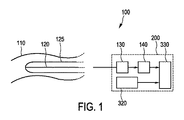
図1は、光学形状検知可能な介入デバイス125及び処理システム200を有する介入システム100の実施形態を概略的及び例示的に示す。介入デバイス125は、被検体110内に配置されるように構成される。介入システム100は、介入デバイス125内に埋め込まれる光学ファイバ及び光源(図示せず)によって、介入デバイス125の少なくとも一部についての光学形状検知データを提供するように構成される光学形状検知ユニット120を有する。処理システム200は、介入デバイス125の再構成された形状データを提供するように構成される再構成形状データ提供ユニット130と、前記再構成された形状データに基づいて少なくとも1つの仮想マーキングを提供するように構成される仮想マーキングプロバイダユニット140と、を有する。再構成形状データ提供ユニット130は、再構成された形状データを供給するために形状再構成を実施する形状再構成ユニットを有することができる。光学形状検知ユニット120は、例えば、光源及び光学ファイバを有することができる。介入デバイス125は、例えばカテーテルのような細長いデバイスを有することができる。以下に詳しく記述されるように、処理システム200は更に、被検体110内の関心領域を表現する関心領域表現を生成するように構成される任意の関心領域表現ユニット320を有することができる。処理システム200は更に、前記介入デバイスが被検体110内の前記関心領域内に配置される際に、前記少なくとも1つの仮想マーキングを前記関心領域表現と位置合わせするように構成される任意の位置合わせユニット330を有することができる。
FIG. 1 schematically and exemplarily shows an embodiment of an
図2は、被検体310内の介入システム100の介入デバイス125をイメージングするイメージングシステム300の実施形態を概略的及び例示的に示す。イメージングシステム300は、例えば1又は複数のX線源301及び1又は複数のX線検出器302を有するX線イメージングシステムでありうる。イメージングシステム300は、処理システム200と、前記関心領域表現と共に前記少なくとも1つの仮想マーキングを表示するように構成される表示ユニット340と、を有する。
FIG. 2 schematically and exemplarily illustrates an embodiment of an
図3は、光学形状検知可能な介入デバイス125に関する少なくとも1つの仮想マーキングを提供する方法400の実施形態を概略的及び例示的に示す。ステップ410は、介入デバイスの少なくとも一部の光学形状検知データを提供することに関連する。ステップ420は、光学形状検知データに基づいて、介入デバイスの再構成された形状データを提供することに関連する。ステップ430は、前記再構成された形状データに基づいて少なくとも1つの仮想マーキングを提供することに関連する。
FIG. 3 schematically and exemplarily illustrates an embodiment of a
図4は、処理方法500の実施形態を概略的及び例示的に示す。ステップ510は、介入デバイス125の再構成された形状データを提供することに関連し、介入デバイス125は、被検体内に配置されるように構成される。ステップ520は、前記再構成された形状データに基づいて少なくとも1つの仮想マーキングを提供することに関連する。
FIG. 4 schematically and exemplarily shows an embodiment of the
図5は、介入デバイス100をイメージングするためのイメージング方法600の実施形態を概略的に及び例示的に示す。ステップ610は、被検体内の関心領域を表現する関心領域表現を生成することに関連する。ステップ620は、被検体内に光学形状検知可能な介入デバイス125を配置すること、及び方法400に従って少なくとも1つの仮想マーキングを提供することに関連する。ステップ630は、前記少なくとも1つの仮想マーキングを、前記関心領域表現と位置合わせすることに関連する。ステップ640は、前記関心領域表現と共に前記少なくとも1つの仮想マーキングを表示することに関連する。
FIG. 5 schematically and exemplarily shows an embodiment of an
光学形状検知技術は、例えば光学ファイバの3次元形状を提供することができる。介入デバイスにこのようなファイバを組み込むことによって、デバイスの形状が、知られることができる。 Optical shape sensing technology can provide, for example, a three-dimensional shape of an optical fiber. By incorporating such a fiber into an interventional device, the shape of the device can be known.
従来の介入デバイスにおいて、患者内部の距離の測定は、例えば血管980(例えば図8に示される)及び放射線不透過性マーカを有するデバイス(例えば図6及び図7に示される)の寸法を決定するために、X線画像900にオーバレイされる放射線不透過ルーラ990により実施される。米国特許出願公開第2010/0318182A1号公報は、知られている相対距離のところに配置される放射線不透過マーカを記述している。米国特許第5,860,923A号公報は、患者の外側にある或る種の可視ルーラにより測定される経路の開始及び終了を示す放射線不透過性マーカを記述している。しかしながら、これらは、多くの場合、測定専用のデバイスであり、容易なナビゲーション又はステント配置のための特性を有さず、又はそのような特性が少ない。
In conventional interventional devices, measurement of distance within the patient determines the dimensions of a device (eg, shown in FIGS. 6 and 7) having, for example, a blood vessel 980 (eg, shown in FIG. 8) and a radiopaque marker. For this purpose, a
X線イメージングのフォアショートニング及び逆パースペクティブのため、X線イメージングのみに基づいて信頼性のある測定を行うことは困難である。すなわち、放射線不透過ルーラのスケールは、ルーラの深さにおける、ビュー方向に対し垂直な平面上でのみ有効である。従って、医師は、しばしば、例えば血管710に導入されるピグテールカテーテル720(図6に図示)、又は較正された硬膜外ニードル820(図7に図示)、のような較正されたデバイスを使用する。放射線不透過マーカは、知られている相対距離のところにあり、ユーザが、マーカを計数し長さを評価することによって、3D長さ測定を行うことを可能にする。主な問題は、すべてのデバイスがこれらのマーキングを有するわけではないので、ユーザが測定を行うことを望むたびに、専用の較正されたデバイスが使用される必要があることである。血管内プロシージャにおいて、ガイドワイヤが適当な位置にあるとき、較正されたデバイスは、それを通じて摺動することができるが、デバイスを入れ替える作業を必要とする。本発明は、OSS可能なデバイスを、較正されたデバイスに変え、それにより、OSS可能なデバイスが使用される場合に専用の較正されたデバイスの必要を除去し、ワークフローを改善し費用を低減する。
Due to the foreshortening and inverse perspective of X-ray imaging, it is difficult to make reliable measurements based solely on X-ray imaging. That is, the scale of the radiopaque ruler is valid only on a plane perpendicular to the view direction at the depth of the ruler. Accordingly, physicians often use calibrated devices such as, for example, a pigtail catheter 720 (shown in FIG. 6) introduced into a
本発明は、任意のOSS可能なデバイスが距離に関する情報を提供することができるという洞察に基づく。デバイスの再構成された形状は、仮想マーカの視覚化を提供することができ、ここで、仮想マーカは、従来の較正されたデバイスの放射線不透過マーカと同じ機能を提供することができる。光学形状検知の実施に基づいて仮想マーキングを用いる場合、より正確なスケールを提供することも可能である。これは、放射線不透過マーカが、ユーザによって評価される2つの位置の間の正確な長さをおきながら特定の厚さを有するという理由による。仮想マーキングは、実際の3Dポイントを含むことができるので、これらのポイントの間の距離は非常に正確である。更に、例えば図9に図示されるように、介入デバイス1020に関する仮想マーキング1020A、1020Bの視覚化は、例えばグラフィクスを変えることによって、改善されることができる。
The present invention is based on the insight that any OSS capable device can provide distance information. The reconfigured shape of the device can provide visualization of a virtual marker, where the virtual marker can provide the same functionality as a radiopaque marker of a conventional calibrated device. It is also possible to provide a more accurate scale when using virtual marking based on the implementation of optical shape detection. This is because the radiopaque marker has a specific thickness while leaving the exact length between the two positions evaluated by the user. Since virtual markings can include actual 3D points, the distance between these points is very accurate. Further, the visualization of the
再構成される形状は、知られている空間(例えばミリメートル空間)において計算される。従って、(すなわち直線ラインに沿った、又は、再構成された形状に沿った)3D距離が、再構成された形状のポイントを使用することによって、この空間において計算されることができる。プロシージャ前又はプロシージャ中のデータの測定を行うために本発明を使用することが望まれる場合、プロシージャ前又はプロシージャ中のデータと位置合わせするコンテクストにおいて、再構成された形状を配置することが好ましい。 The reconstructed shape is calculated in a known space (eg millimeter space). Thus, a 3D distance (ie along a straight line or along a reconstructed shape) can be calculated in this space by using the points of the reconstructed shape. If it is desired to use the present invention to perform pre-procedure or intra-procedure data measurements, it is preferable to place the reconstructed shape in a context that aligns with the pre-procedure or intra-procedure data.
改善されたユーザ経験は、仮想マーキングをラベル付けすることによって達成されることができ、それにより、ユーザは、各々の仮想マーキングを数える必要がない。実施形態において、ビューが、あまり混雑して見えないように、仮想マーカは、オン/オフを切り換えられることができる。これは特に、ユーザが測定を行わないときに有用である。マーキングのスケール(単位サイズ)は、ユーザの好みに合わせて(センチメートル又はミリメートル)、又は地理的領域の標準に合わせて(メートル法又は英単位系)、調整されることができる。これを行うことができる1つの利点は、物理的なデバイスが変えられる必要がないということである。別の実施形態において、スケールは、ユーザがどれくらいズームインするかに依存して作られることができる。 An improved user experience can be achieved by labeling the virtual markings so that the user does not have to count each virtual marking. In embodiments, the virtual marker can be switched on / off so that the view does not appear too crowded. This is particularly useful when the user does not make a measurement. The marking scale (unit size) can be adjusted to user preferences (centimeters or millimeters) or to geographic area standards (metric or English units). One advantage that can do this is that the physical device does not need to be changed. In another embodiment, the scale can be created depending on how much the user zooms in.
図10に示されるように、ライブの角度測定は、3つの仮想マーキングを選択し、すなわち被検体1110内の介入デバイス1120上で3つの3D位置1101、1102、1103を選択することによって、行われることができる。本発明によって提案される3D形状を用いない場合、角度1104は、例えばCT又はMRから得られる術前ボリューム上で計算されることができるが、これは、解剖学的構造の歪みにより不正確でありうる。角度1104は更に、プロシージャ中の回転X線スキャンから得られるボリューム上で計算されることができるが、これは、追加のX線曝露及びおそらく付加の(毒性の)造影剤を必要とする。X線画像において直接実施される従来の角度測定は、X線のフォアショートニング及び逆投影の理由で、低い正確さを示す。更に、面内角度のみが、X線画像から決定されることができる。本発明によって提案される3D形状を使用することによって、これらの欠点が、解決されることができる。
As shown in FIG. 10, live angle measurement is performed by selecting three virtual markings, ie, selecting three
ユーザは、ライブの形状又は記録された(静止)形状を使用してポイントを選択することができる。 The user can select points using live shapes or recorded (static) shapes.
ある角度は、例えば固定ポイントを使用することによって又は形状の曲率に注目することによって、自動的に計算されることができる。角度測定は更に、デバイス上で2つの3D位置を2回選択することによって、行われることができる。これらのポイント対は、2本のラインを規定し、ライン間の角度が、計算されることができる。 An angle can be calculated automatically, for example by using a fixed point or by noting the curvature of the shape. Angular measurements can also be made by selecting two 3D positions twice on the device. These point pairs define two lines and the angle between the lines can be calculated.
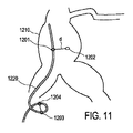
図11に示されるように、被検体1210内の介入デバイス1220上のポイント1203、1204間の距離が、計算され、ユーザに表示されることができる(それにより、デバイスに沿った長さだけでなく、2つのポイント間のユークリッド最短距離も計算される)。更に、仮想マーキング1201と被検体1210内の予め規定されたロケーション1202との間の距離dが、決定されることができる。特定の時間期間中にデバイスの先端(又は任意の他の特定のポイント)が進行した経路の長さが、ユーザにとって有用なことがある。このために、デバイスの全体の形状が知られている必要はなく、時間にわたってデバイス上の1つのポイントの位置のみが知られればよい。それゆえ、この利点は、OSSに適用できるだけでなく、時間にわたってポイントを追跡することができる他のモダリティにも適用できる。
As shown in FIG. 11, the distance between
複数のOSS可能な介入デバイスを使用した測定は、以下のように行われることができる:1つのデバイスが他のルーメン内にある場合、例えば、ガイドワイヤがカテーテル内部にある場合、1つの遠位先端から他のデバイスの遠位先端へのデバイスに沿った距離が、計算され、ユーザに表示されることができる。これは、先端同士が互いのところに届く前に、デバイスがどの程度挿入されることができるかの情報をユーザに与えることを可能にする。それは更に、病変の一端において各々の先端を保持することによって、迅速な長さ測定を行うために使用されることができ、それにより、長さが直接算出されることができる。更に、両方の介入デバイスが互いに内部にあるか否かに関係なく、複数のデバイス上の(ユーザ規定される)固定の仮想マーキングの間のライブの距離が、決定されることができる。 Measurements using multiple OSS-capable interventional devices can be performed as follows: if one device is in another lumen, for example if the guidewire is inside the catheter, one distal The distance along the device from the tip to the distal tip of the other device can be calculated and displayed to the user. This allows the user to be informed of how much the device can be inserted before the tips reach each other. It can further be used to make a quick length measurement by holding each tip at one end of the lesion so that the length can be calculated directly. Furthermore, regardless of whether both interventional devices are internal to each other, the live distance between fixed (user-defined) virtual markings on multiple devices can be determined.
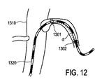
位置合わせされた3Dボリューム又は3D解剖学的ランドマークを使用した測定は、規定される3Dロケーション(ランドマーク)とデバイス上の固定位置との間の距離を決定すること、及び規定された3Dロケーション(ランドマーク)1202と介入デバイス1220(図11を参照)との間の最短距離を決定すること、を含むことができる。これを行う1つのやり方は、3Dロケーション(ランドマーク)1202に最も近い介入デバイス1220上の仮想マーキング1201を識別し、仮想マーキング1201と3Dロケーション(ランドマーク)1202との間の距離dを決定することである。位置合わせされた3Dボリューム又は3D解剖学的ランドマークを使用した測定は更に、セグメント化された血管の中心線までの最短/平均/最大の距離を決定することを含むことができる。位置合わせされた3Dボリューム又は3D解剖学的ランドマークを使用した測定は更に、例えば石灰化、心門及び/又は血管壁のような(セグメント化された)解剖学的特徴までの距離を決定することを含むことができる。位置合わせされた3Dボリューム又は3D解剖学的ランドマークを使用した測定は、(例えばリングによって規定される)平面との交点までの(ユークリッド又はデバイスに沿った)距離を決定することを含むことができる。これは、介入デバイス1320が被検体1310に導入されている図12に示されている。仮想マーキング1301、1302の間の距離dは、2つの平面(図12にリングとして示される)との交点を識別し、介入デバイス1320に沿った距離dを決定することによって、決定される。
Measurements using aligned 3D volumes or 3D anatomical landmarks determine the distance between a defined 3D location (landmark) and a fixed position on the device, and a defined 3D location Determining a shortest distance between the (landmark) 1202 and the interventional device 1220 (see FIG. 11). One way of doing this is to identify the
デバイスは、ボリュームの切断面を決定することができる。この面において、(血管輪郭の)面積及び血管壁に対す最短距離のような2D測定が行われることができる。例えばユーザによってクリックされる先端又は位置のような形状上の位置は、固定され、3Dランドマークとして記憶されることができる。ユーザは、X線画像上に2Dランドマークを配置することができ、これを、デバイスとの組み合わせにおいて距離測定(最短距離又は形状上の或るポイントまでの距離)のために使用することができる。2Dランドマークは、例えばX線システムのソースから検出器までの3Dラインを記述することができる。その距離は、2Dランドマークでタグ付けされた解剖学的特徴とデバイスとの間の正確な距離ではなく、その理由は、解剖学的特徴がライン上のどこに位置付けられるか知られていないからである。 The device can determine the cut surface of the volume. In this plane, 2D measurements such as the area (of the blood vessel contour) and the shortest distance to the blood vessel wall can be made. For example, the position on the shape, such as the tip or position clicked by the user, can be fixed and stored as a 3D landmark. The user can place a 2D landmark on the X-ray image, which can be used for distance measurement (shortest distance or distance to a point on the shape) in combination with the device. . The 2D landmark can describe a 3D line from the source to the detector of the X-ray system, for example. The distance is not the exact distance between the anatomical feature tagged with the 2D landmark and the device because it is not known where the anatomical feature is located on the line. is there.
実際的な距離のある種の評価である距離をユーザに提供するための異なるオプションがある。ライン上の位置は、デバイス上の位置と同じ深さを有することができるので、測定は、X線画像に対して垂直な平面にある。位置は更に、アイソセンタを通り及びX線画像に対し垂直である平面内のライン上にあってもよい。ユーザは、例えば異なる角度から作られる画像の助けにより、深さを決定することができる。 There are different options for providing the user with a distance that is some kind of evaluation of the practical distance. Since the location on the line can have the same depth as the location on the device, the measurement is in a plane perpendicular to the x-ray image. The position may also be on a line in a plane that passes through the isocenter and is perpendicular to the x-ray image. The user can determine the depth, for example with the help of images made from different angles.
上述の実施形態にて説明したように、(例えばデバイス上、3Dボリューム上、又はX線上で)選択された3Dポイントは、ポイント間の3D距離のみを提供することに代わって、3D仮想ルーラを規定するために使用されることができる。このようにして、X線で可視であるコンテントの距離情報が、より正確に測定されることができる。同様に、3つの3Dポイントは、ルーラグリッドのために使用されることができる3D平面を規定することができ、測定は、この平面において行われることができる。 As described in the above embodiments, selected 3D points (eg, on a device, on a 3D volume, or on X-rays) can provide a 3D virtual ruler instead of providing only a 3D distance between points. Can be used to prescribe. In this way, content distance information visible with X-rays can be measured more accurately. Similarly, the three 3D points can define a 3D plane that can be used for the ruler grid, and measurements can be made in this plane.
デバイスの位置及び形状は、ビューイング位置(例えばテーブル及びCアーム位置)の提案を提供することができる。ユーザは、形状上に3つのポイントを規定することができ、3つのポイントは、ビュー平面を記述する。平面は、特定のポイント、曲率、特定のポイントの方向又はこれら全ての組み合わせに基づいて、自動的に計算されることができる。 The position and shape of the device can provide suggestions for viewing positions (eg, table and C-arm positions). The user can define three points on the shape, and the three points describe the view plane. The plane can be automatically calculated based on a particular point, curvature, direction of a particular point, or a combination of all.
他の実施形態は、図13によって示されており、図13において、介入デバイス1420が、例えば血管のような被検体1410に導入される。仮想マーキング1401が、介入デバイス1420の先端に提供される。本発明は、血管壁1402までの距離d(好適には最短距離)を決定するために使用されることができる。
Another embodiment is illustrated by FIG. 13, in which an
図14は、処理システム200Aの他の実施形態を概略的及び例示的に示す。処理装置200Aは、介入デバイス100の再構成された形状データ220を受け取るように構成される受信ユニット210を有し、受信ユニット210は、入力ユニットを有することができる。処理装置200Aは更に、前記再構成された形状データ220に基づいて少なくとも1つの仮想マーキングを提供するように構成される仮想マーキングプロバイダユニット140Aを有する。
FIG. 14 schematically and exemplarily shows another embodiment of the
本発明の例示のアプリケーションは、OSS可能なデバイスを有する任意の(医学的な及び非医学的な)アプリケーションである。 An exemplary application of the present invention is any (medical and non-medical) application that has an OSS-capable device.
処理装置のすべての装置構成は、本発明による光学形状検知可能な介入デバイス及び/又はイメージング装置と共に使用されることができる。 All apparatus configurations of the processing apparatus can be used with an optical shape sensitive interventional device and / or imaging apparatus according to the present invention.
開示された実施形態に対する他の変更は、図面、開示及び添付の請求項の検討から、請求項に記載の本発明を実施する際に当業者によって理解され達成されることができる。 Other modifications to the disclosed embodiments can be understood and attained by those skilled in the art in practicing the claimed invention, from a study of the drawings, the disclosure, and the appended claims.
請求項において、「含む、有する(comprising)」という語は、他の構成要素又はステップを除外せず、不定冠詞「a」又は「an」は、複数性を除外しない。 In the claims, the word “comprising” does not exclude other elements or steps, and the indefinite article “a” or “an” does not exclude a plurality.
単一のユニット又はデバイスは、請求項に列挙されているいくつかのアイテムの機能を果たすことができる。特定の手段が相互に異なる従属請求項に列挙されているという単なる事実は、これらの手段の組み合わせが有利に使用されることができないことを示さない。 A single unit or device may fulfill the functions of several items recited in the claims. The mere fact that certain measures are recited in mutually different dependent claims does not indicate that a combination of these measured cannot be used to advantage.
1又は複数のユニット又は装置によって実施される距離及び角度測定、その他の算出は、他の数のユニット又はデバイスによって実施されることができる。例えば、2つの仮想マーキングの間の距離の決定は、単一ユニットによって又は他の数のユニットによって実施されることができる。上述した処理方法による処理装置の制御は、コンピュータプログラムのプログラムコード手段として及び/又は専用ハードウェアとして、実現されることができる。上述したイメージング方法によるイメージング装置の制御は、コンピュータプログラムのプログラムコード手段として及び/又は専用のハードウェアとして実現されることができる。 Distance and angle measurements and other calculations performed by one or more units or devices can be performed by other numbers of units or devices. For example, the determination of the distance between two virtual markings can be performed by a single unit or by other numbers of units. The control of the processing apparatus by the processing method described above can be realized as program code means of a computer program and / or as dedicated hardware. Control of the imaging apparatus by the above-described imaging method can be realized as program code means of a computer program and / or as dedicated hardware.
コンピュータプログラムは、他のハードウェアと共に又はその一部として供給される光学記憶媒体又はソリッドステート媒体のような適切な媒体に記憶され/分散されることができるが、他の形で、例えばインターネット又は他のワイヤード若しくはワイヤレス通信システムを通じて、分散されることもできる。 The computer program may be stored / distributed on suitable media, such as optical storage media or solid state media supplied with or as part of other hardware, but in other forms such as the Internet or It can also be distributed through other wired or wireless communication systems.
請求項におけるいかなる参照符号も、請求項の範囲を制限するものとして解釈されるべきでない。 Any reference signs in the claims should not be construed as limiting the scope of the claims.
本発明は、例えば光学ファイバを有するカテーテルのような光学形状検知可能な介入デバイスと協働するように構成される処理システムに関する。再構成形状データ提供ユニットは、介入デバイスの再構成された形状データを提供する。仮想マーキングプロバイダユニットは、再構成された形状データに基づいて、例えばX線画像へのオーバレイとして少なくとも1つの仮想マーキングを提供する。本発明は、任意のOSS可能なデバイスを、すべての種類のライブの3D測定に適した較正されたデバイスにかえる。 The present invention relates to a processing system configured to cooperate with an optical shape-sensitive interventional device, such as a catheter having optical fibers. The reconstructed shape data providing unit provides reconstructed shape data of the interventional device. The virtual marking provider unit provides at least one virtual marking, for example as an overlay to the X-ray image, based on the reconstructed shape data. The present invention replaces any OSS capable device with a calibrated device suitable for all types of live 3D measurements.
Claims (11)
前記介入デバイスの、メトリック空間における再構成された形状データを提供するように構成される再構成形状データ提供ユニットと、
前記介入デバイスを較正されたデバイスにするために、複数の仮想マーキングを、前記介入デバイスの再構成された形状上に提供するように構成される仮想マーキングプロバイダユニットであって、前記複数の仮想マーキングの間の相対距離が、前記メトリック空間の前記再構成された形状データに基づいて算出される、仮想マーキングプロバイダユニットと、
を有する処理システム。 A processing system configured to cooperate with an elongate interventional device capable of optical shape sensing, wherein the interventional device is configured to be disposed within a subject, the processing system comprising:
A reconstructed shape data providing unit configured to provide reconstructed shape data in a metric space of the interventional device;
A virtual marking provider unit configured to provide a plurality of virtual markings on a reconfigured shape of the interventional device to make the interventional device a calibrated device, the plurality of virtual markings A virtual marking provider unit, wherein a relative distance between is calculated based on the reconstructed shape data of the metric space ;
Having a processing system.
前記被検体内の関心領域を表現する関心領域表現を生成するように構成される関心領域表現ユニットと、
前記介入デバイスが前記被検体内に配される場合に前記仮想マーキングを前記関心領域表現と位置合わせするように構成される位置合わせユニットと、
を有する、請求項1に記載の処理システム。 The processing system further comprises:
A region of interest representation unit configured to generate a region of interest representation that represents a region of interest in the subject;
An alignment unit configured to align the virtual marking with the region of interest representation when the interventional device is disposed within the subject;
The processing system according to claim 1, comprising:
請求項1に記載の処理システムと、
前記仮想マーキングを表示するように構成される表示ユニットと、
を有するイメージングシステム。 An imaging system for imaging an elongated interventional device in a subject,
A processing system according to claim 1;
A display unit configured to display the virtual marking;
An imaging system.
前記被検体内の関心領域を表現する関心領域表現を生成するように構成される関心領域表現ユニットと、
前記介入デバイスが前記被検体内に配される場合に前記仮想マーキングを前記関心領域表現と位置合わせするように構成される位置合わせユニットと、を有し、
前記表示ユニットが、前記関心領域表現と共に前記仮想マーキングを表示するように構成される、請求項7に記載のイメージングシステム。 The processing system further comprises:
A region of interest representation unit configured to generate a region of interest representation that represents a region of interest in the subject;
An alignment unit configured to align the virtual marking with the region of interest representation when the interventional device is disposed within the subject;
The imaging system of claim 7, wherein the display unit is configured to display the virtual marking along with the region of interest representation.
被検体内に配されるように構成された光学形状検知可能な細長い介入デバイスの、メトリック空間における再構成された形状データを提供するステップと、
前記介入デバイスを較正されたデバイスにするために、複数の仮想マーキングを、前記介入デバイスの再構成された形状上に提供するステップであって、前記複数の仮想マーキングの間の相対距離が、前記メトリック空間の前記再構成された形状データに基づいて算出される、ステップと、
を実行する方法。 Computer processor
Providing reconstructed shape data in metric space of an optical shape-sensitive elongate interventional device configured to be disposed within a subject;
Providing a plurality of virtual markings on the reconstructed shape of the interventional device to make the interventional device a calibrated device , wherein the relative distance between the plurality of virtual markings is Calculated based on the reconstructed shape data of a metric space; and
How to run .
Applications Claiming Priority (3)
| Application Number | Priority Date | Filing Date | Title |
|---|---|---|---|
| EP14184869.7 | 2014-09-16 | ||
| EP14184869 | 2014-09-16 | ||
| PCT/EP2015/070309 WO2016041793A1 (en) | 2014-09-16 | 2015-09-06 | Processing system arranged to cooperate with an optical-shape-sensing-enabled interventional device |
Publications (3)
| Publication Number | Publication Date |
|---|---|
| JP2017534315A JP2017534315A (en) | 2017-11-24 |
| JP2017534315A5 JP2017534315A5 (en) | 2018-10-11 |
| JP6496403B2 true JP6496403B2 (en) | 2019-04-03 |
Family
ID=51582247
Family Applications (1)
| Application Number | Title | Priority Date | Filing Date |
|---|---|---|---|
| JP2017512954A Active JP6496403B2 (en) | 2014-09-16 | 2015-09-06 | A processing system configured to cooperate with an optical shape sensitive interventional device |
Country Status (5)
| Country | Link |
|---|---|
| US (1) | US10238463B2 (en) |
| EP (1) | EP3193765B1 (en) |
| JP (1) | JP6496403B2 (en) |
| CN (1) | CN107072743B (en) |
| WO (1) | WO2016041793A1 (en) |
Families Citing this family (10)
| Publication number | Priority date | Publication date | Assignee | Title |
|---|---|---|---|---|
| EP3979047A1 (en) | 2016-02-02 | 2022-04-06 | Sony Group Corporation | Information processing apparatus, information processing method, and recording medium |
| WO2018104162A1 (en) * | 2016-12-05 | 2018-06-14 | Koninklijke Philips N.V. | Systems and methods for determining the length of a non-shape-sensed interventional device with a shape-sensed guidewire and determining a state of the guidewire with respect to an interventional device |
| EP3554367B1 (en) | 2016-12-13 | 2023-03-22 | Koninklijke Philips N.V. | Systems and methods for determining the position of a non-shape-sensed guidewire with a shape-sensed catheter and for visualizing the guidewire |
| WO2018178248A1 (en) * | 2017-03-30 | 2018-10-04 | Koninklijke Philips N.V. | Oss foreshortening detection systems |
| EP3735696A1 (en) | 2018-01-02 | 2020-11-11 | Koninklijke Philips N.V. | Animated position display of an oss interventional device |
| EP3542747A1 (en) | 2018-03-22 | 2019-09-25 | Koninklijke Philips N.V. | Visualization system for visualizing an alignment accuracy |
| EP3682836A1 (en) * | 2019-01-21 | 2020-07-22 | Koninklijke Philips N.V. | Assisting in moving an insertion element within an object |
| CN211884905U (en) | 2019-08-22 | 2020-11-10 | 贝克顿·迪金森公司 | Balloon dilatation catheter and balloon thereof |
| EP3838209A1 (en) * | 2019-12-20 | 2021-06-23 | Koninklijke Philips N.V. | Generating interactive zones for interventional medical devices |
| CN113180824B (en) * | 2021-03-29 | 2023-06-20 | 杭州脉流科技有限公司 | Shaping needle form simulation method and device for microcatheter shaping, computer equipment and storage medium |
Family Cites Families (30)
| Publication number | Priority date | Publication date | Assignee | Title |
|---|---|---|---|---|
| EP0723786A1 (en) | 1995-01-30 | 1996-07-31 | Cardiovascular Concepts, Inc. | Lesion measurement catheter and method |
| JP2001070439A (en) | 1999-09-07 | 2001-03-21 | Kiisumakku:Kk | Gage for indwelling urethral stent |
| JP3631151B2 (en) * | 2000-11-30 | 2005-03-23 | キヤノン株式会社 | Information processing apparatus, mixed reality presentation apparatus and method, and storage medium |
| US20030227542A1 (en) * | 2001-12-20 | 2003-12-11 | Xiang Zhang | Single-computer real-time stereo augmented reality system |
| US8348824B2 (en) | 2007-11-30 | 2013-01-08 | Cytyc Corporation | Transparent catheters for endoscopic localization |
| WO2009081367A1 (en) | 2007-12-19 | 2009-07-02 | Universite De Lausanne | Calibrated sheath with markings |
| US20090182225A1 (en) | 2008-01-03 | 2009-07-16 | Ceramoptec Industries Inc. | Safety Marked Fibers and Catheters |
| JP4517004B2 (en) | 2008-06-16 | 2010-08-04 | ノリー株式会社 | Injection needle guidance device |
| US10004387B2 (en) | 2009-03-26 | 2018-06-26 | Intuitive Surgical Operations, Inc. | Method and system for assisting an operator in endoscopic navigation |
| US9445745B2 (en) * | 2009-12-31 | 2016-09-20 | Mediguide Ltd. | Tool shape estimation |
| RU2726159C2 (en) * | 2010-10-27 | 2020-07-09 | Конинклейке Филипс Электроникс Н.В. | Adaptive imaging and frame rate optimization based on real-time recognition of the shape of medical instruments |
| US8907969B2 (en) | 2010-12-13 | 2014-12-09 | Advanced Micro Devices, Inc. | Partially resident textures |
| CN103347460B (en) | 2011-01-27 | 2017-04-19 | 皇家飞利浦电子股份有限公司 | Integration of fiber optic shape sensing within interventional environment |
| US10820830B2 (en) | 2011-01-28 | 2020-11-03 | Koninklijke Philips N.V. | Reference markers for launch point identification in optical shape sensing systems |
| JP6270483B2 (en) | 2011-01-28 | 2018-01-31 | コーニンクレッカ フィリップス エヌ ヴェKoninklijke Philips N.V. | 3D shape reconstruction for optical tracking of elongated devices |
| US10537428B2 (en) | 2011-04-28 | 2020-01-21 | Koninklijke Philips N.V. | Guided delivery of prosthetic valve |
| EP2742329B1 (en) * | 2011-09-02 | 2017-12-27 | Koninklijke Philips N.V. | Medical device insertion and exit information using distributed fiber optic temperature sensing |
| US9264542B2 (en) | 2011-11-30 | 2016-02-16 | At&T Mobility Ii Llc | Personalizing communications services using environmental data |
| EP2825839B1 (en) | 2012-03-16 | 2021-05-12 | Koninklijke Philips N.V. | An optical sensing system for determining the position and/or shape of an associated object |
| CN104350808B (en) | 2012-06-29 | 2018-10-16 | 英特尔公司 | For using the mobile equipment for safely matching mobile communication equipment, method and system |
| WO2014053934A1 (en) | 2012-10-01 | 2014-04-10 | Koninklijke Philips N.V. | System and method for registering shape sensing with imaging using an optimal plane |
| RU2638445C2 (en) | 2012-10-01 | 2017-12-13 | Конинклейке Филипс Н.В. | Three-dimensional polylinear combination with use of limitations of form |
| WO2014060889A1 (en) | 2012-10-16 | 2014-04-24 | Koninklijke Philips N.V. | Pulmonary plethysmography based on optical shape sensing |
| US20140135744A1 (en) | 2012-11-09 | 2014-05-15 | Orthosensor Inc | Motion and orientation sensing module or device for positioning of implants |
| CN105101895B (en) * | 2013-03-28 | 2019-11-26 | 皇家飞利浦有限公司 | Instrument positioning in guided high dose rate plesioradiotherapy |
| JP6693869B2 (en) * | 2013-10-02 | 2020-05-13 | コーニンクレッカ フィリップス エヌ ヴェKoninklijke Philips N.V. | Device tracking using longitudinal encoding |
| WO2016041792A1 (en) * | 2014-09-16 | 2016-03-24 | Koninklijke Philips N.V. | Interventional apparatus for performing an interventional procedure |
| CN106999732B (en) * | 2014-12-10 | 2020-09-29 | 皇家飞利浦有限公司 | Tracking shape reconstruction for interventional procedure guidance |
| JP6612873B2 (en) * | 2014-12-11 | 2019-11-27 | コーニンクレッカ フィリップス エヌ ヴェ | Automatic selection of optimal calibration in tracking interventional procedures |
| JP6584518B2 (en) * | 2015-02-20 | 2019-10-02 | コーニンクレッカ フィリップス エヌ ヴェKoninklijke Philips N.V. | Medical system, apparatus and method for shape detection |
-
2015
- 2015-09-06 JP JP2017512954A patent/JP6496403B2/en active Active
- 2015-09-06 US US15/510,373 patent/US10238463B2/en active Active
- 2015-09-06 CN CN201580049837.8A patent/CN107072743B/en active Active
- 2015-09-06 WO PCT/EP2015/070309 patent/WO2016041793A1/en active Application Filing
- 2015-09-06 EP EP15760154.3A patent/EP3193765B1/en active Active
Also Published As
| Publication number | Publication date |
|---|---|
| CN107072743B (en) | 2020-07-28 |
| WO2016041793A1 (en) | 2016-03-24 |
| JP2017534315A (en) | 2017-11-24 |
| EP3193765B1 (en) | 2018-12-12 |
| EP3193765A1 (en) | 2017-07-26 |
| US20170281293A1 (en) | 2017-10-05 |
| US10238463B2 (en) | 2019-03-26 |
| CN107072743A (en) | 2017-08-18 |
Similar Documents
| Publication | Publication Date | Title |
|---|---|---|
| JP6496403B2 (en) | A processing system configured to cooperate with an optical shape sensitive interventional device | |
| JP5639352B2 (en) | Device for tracking the movement of foreign objects in a subject | |
| JP5207795B2 (en) | System and method for navigating an object being imaged | |
| JP6693869B2 (en) | Device tracking using longitudinal encoding | |
| RU2445007C2 (en) | Superposition of coordinate systems | |
| JP2023053108A (en) | Image registration and guidance using concurrent x-plane imaging | |
| US9955920B2 (en) | Dynamic mapping point filtering using a pre-acquired image | |
| RU2464931C2 (en) | Device for determining position of first object inside second object | |
| FR2908628A1 (en) | METHOD AND SYSTEM FOR CONTROLLING A MEDICAL INSTRUMENT | |
| US7603159B2 (en) | Method for transcutaneous catheter guiding | |
| US11602396B2 (en) | OSS foreshortening detection systems, controllers and methods | |
| CN110301883A (en) | The guide based on image for the tubulose network that navigates | |
| US20090124895A1 (en) | Imaging system for medical needle procedures | |
| EP3515288B1 (en) | Visualization of an image object relating to an instrument in an extracorporeal image | |
| CN107106242B (en) | Interventional radiology medical system | |
| CN110022786B (en) | Position determination device for determining the position of an instrument within a tubular structure | |
| EP4093275A1 (en) | Intraoperative 2d/3d imaging platform | |
| WO2020152051A1 (en) | Assisting in moving an insertion element within an object |
Legal Events
| Date | Code | Title | Description |
|---|---|---|---|
| A521 | Request for written amendment filed |
Free format text: JAPANESE INTERMEDIATE CODE: A523 Effective date: 20180831 |
|
| A621 | Written request for application examination |
Free format text: JAPANESE INTERMEDIATE CODE: A621 Effective date: 20180831 |
|
| A871 | Explanation of circumstances concerning accelerated examination |
Free format text: JAPANESE INTERMEDIATE CODE: A871 Effective date: 20180831 |
|
| A975 | Report on accelerated examination |
Free format text: JAPANESE INTERMEDIATE CODE: A971005 Effective date: 20181121 |
|
| A131 | Notification of reasons for refusal |
Free format text: JAPANESE INTERMEDIATE CODE: A131 Effective date: 20181127 |
|
| A521 | Request for written amendment filed |
Free format text: JAPANESE INTERMEDIATE CODE: A523 Effective date: 20190220 |
|
| TRDD | Decision of grant or rejection written | ||
| A01 | Written decision to grant a patent or to grant a registration (utility model) |
Free format text: JAPANESE INTERMEDIATE CODE: A01 Effective date: 20190305 |
|
| A61 | First payment of annual fees (during grant procedure) |
Free format text: JAPANESE INTERMEDIATE CODE: A61 Effective date: 20190308 |
|
| R150 | Certificate of patent or registration of utility model |
Ref document number: 6496403 Country of ref document: JP Free format text: JAPANESE INTERMEDIATE CODE: R150 |
|
| R250 | Receipt of annual fees |
Free format text: JAPANESE INTERMEDIATE CODE: R250 |
|
| R250 | Receipt of annual fees |
Free format text: JAPANESE INTERMEDIATE CODE: R250 |
|
| R250 | Receipt of annual fees |
Free format text: JAPANESE INTERMEDIATE CODE: R250 |