EP2742329B1 - Medical device insertion and exit information using distributed fiber optic temperature sensing - Google Patents
Medical device insertion and exit information using distributed fiber optic temperature sensing Download PDFInfo
- Publication number
- EP2742329B1 EP2742329B1 EP12778422.1A EP12778422A EP2742329B1 EP 2742329 B1 EP2742329 B1 EP 2742329B1 EP 12778422 A EP12778422 A EP 12778422A EP 2742329 B1 EP2742329 B1 EP 2742329B1
- Authority
- EP
- European Patent Office
- Prior art keywords
- temperature
- sensing
- recited
- workstation
- strain
- Prior art date
- Legal status (The legal status is an assumption and is not a legal conclusion. Google has not performed a legal analysis and makes no representation as to the accuracy of the status listed.)
- Active
Links
- 239000000835 fiber Substances 0.000 title description 50
- 238000003780 insertion Methods 0.000 title description 10
- 230000037431 insertion Effects 0.000 title description 10
- 239000013307 optical fiber Substances 0.000 claims description 33
- 230000003287 optical effect Effects 0.000 claims description 21
- 230000007704 transition Effects 0.000 claims description 19
- 238000000034 method Methods 0.000 description 18
- 238000003384 imaging method Methods 0.000 description 12
- 238000005259 measurement Methods 0.000 description 8
- 230000006870 function Effects 0.000 description 6
- 238000010586 diagram Methods 0.000 description 5
- 230000008859 change Effects 0.000 description 4
- 238000002591 computed tomography Methods 0.000 description 4
- 238000003860 storage Methods 0.000 description 4
- VYPSYNLAJGMNEJ-UHFFFAOYSA-N Silicium dioxide Chemical group O=[Si]=O VYPSYNLAJGMNEJ-UHFFFAOYSA-N 0.000 description 3
- 238000002679 ablation Methods 0.000 description 3
- 238000013459 approach Methods 0.000 description 3
- 230000008901 benefit Effects 0.000 description 3
- 230000036760 body temperature Effects 0.000 description 3
- 238000009877 rendering Methods 0.000 description 3
- 238000009529 body temperature measurement Methods 0.000 description 2
- 238000001514 detection method Methods 0.000 description 2
- 238000001727 in vivo Methods 0.000 description 2
- 238000013152 interventional procedure Methods 0.000 description 2
- 230000003902 lesion Effects 0.000 description 2
- 239000000463 material Substances 0.000 description 2
- 230000004044 response Effects 0.000 description 2
- 239000004065 semiconductor Substances 0.000 description 2
- 238000004378 air conditioning Methods 0.000 description 1
- 238000005452 bending Methods 0.000 description 1
- 230000005540 biological transmission Effects 0.000 description 1
- 238000001574 biopsy Methods 0.000 description 1
- 210000004204 blood vessel Anatomy 0.000 description 1
- 239000003086 colorant Substances 0.000 description 1
- 238000004891 communication Methods 0.000 description 1
- 238000004590 computer program Methods 0.000 description 1
- 238000013461 design Methods 0.000 description 1
- 230000001066 destructive effect Effects 0.000 description 1
- 230000000694 effects Effects 0.000 description 1
- 230000005672 electromagnetic field Effects 0.000 description 1
- 238000005516 engineering process Methods 0.000 description 1
- 230000007613 environmental effect Effects 0.000 description 1
- 238000002594 fluoroscopy Methods 0.000 description 1
- 230000004927 fusion Effects 0.000 description 1
- 210000001035 gastrointestinal tract Anatomy 0.000 description 1
- 230000009477 glass transition Effects 0.000 description 1
- 238000011065 in-situ storage Methods 0.000 description 1
- 230000003993 interaction Effects 0.000 description 1
- 238000001990 intravenous administration Methods 0.000 description 1
- 230000004807 localization Effects 0.000 description 1
- 210000004072 lung Anatomy 0.000 description 1
- 238000002324 minimally invasive surgery Methods 0.000 description 1
- 238000012986 modification Methods 0.000 description 1
- 230000004048 modification Effects 0.000 description 1
- 238000012544 monitoring process Methods 0.000 description 1
- 210000000056 organ Anatomy 0.000 description 1
- 230000000737 periodic effect Effects 0.000 description 1
- 230000002093 peripheral effect Effects 0.000 description 1
- 238000009428 plumbing Methods 0.000 description 1
- 230000008569 process Effects 0.000 description 1
- 238000012545 processing Methods 0.000 description 1
- 238000001454 recorded image Methods 0.000 description 1
- 239000000523 sample Substances 0.000 description 1
- 239000000377 silicon dioxide Substances 0.000 description 1
- 239000007787 solid Substances 0.000 description 1
- 230000003595 spectral effect Effects 0.000 description 1
- 238000001356 surgical procedure Methods 0.000 description 1
- 230000002277 temperature effect Effects 0.000 description 1
- 230000001225 therapeutic effect Effects 0.000 description 1
- 238000002604 ultrasonography Methods 0.000 description 1
- 230000000007 visual effect Effects 0.000 description 1
Images


Classifications
-
- A—HUMAN NECESSITIES
- A61—MEDICAL OR VETERINARY SCIENCE; HYGIENE
- A61B—DIAGNOSIS; SURGERY; IDENTIFICATION
- A61B5/00—Measuring for diagnostic purposes; Identification of persons
- A61B5/01—Measuring temperature of body parts ; Diagnostic temperature sensing, e.g. for malignant or inflamed tissue
- A61B5/015—By temperature mapping of body part
-
- A—HUMAN NECESSITIES
- A61—MEDICAL OR VETERINARY SCIENCE; HYGIENE
- A61B—DIAGNOSIS; SURGERY; IDENTIFICATION
- A61B5/00—Measuring for diagnostic purposes; Identification of persons
- A61B5/0059—Measuring for diagnostic purposes; Identification of persons using light, e.g. diagnosis by transillumination, diascopy, fluorescence
- A61B5/0082—Measuring for diagnostic purposes; Identification of persons using light, e.g. diagnosis by transillumination, diascopy, fluorescence adapted for particular medical purposes
- A61B5/0084—Measuring for diagnostic purposes; Identification of persons using light, e.g. diagnosis by transillumination, diascopy, fluorescence adapted for particular medical purposes for introduction into the body, e.g. by catheters
-
- G—PHYSICS
- G01—MEASURING; TESTING
- G01K—MEASURING TEMPERATURE; MEASURING QUANTITY OF HEAT; THERMALLY-SENSITIVE ELEMENTS NOT OTHERWISE PROVIDED FOR
- G01K3/00—Thermometers giving results other than momentary value of temperature
- G01K3/08—Thermometers giving results other than momentary value of temperature giving differences of values; giving differentiated values
- G01K3/14—Thermometers giving results other than momentary value of temperature giving differences of values; giving differentiated values in respect of space
-
- A—HUMAN NECESSITIES
- A61—MEDICAL OR VETERINARY SCIENCE; HYGIENE
- A61B—DIAGNOSIS; SURGERY; IDENTIFICATION
- A61B5/00—Measuring for diagnostic purposes; Identification of persons
- A61B5/06—Devices, other than using radiation, for detecting or locating foreign bodies ; determining position of probes within or on the body of the patient
- A61B5/061—Determining position of a probe within the body employing means separate from the probe, e.g. sensing internal probe position employing impedance electrodes on the surface of the body
-
- G—PHYSICS
- G01—MEASURING; TESTING
- G01K—MEASURING TEMPERATURE; MEASURING QUANTITY OF HEAT; THERMALLY-SENSITIVE ELEMENTS NOT OTHERWISE PROVIDED FOR
- G01K11/00—Measuring temperature based upon physical or chemical changes not covered by groups G01K3/00, G01K5/00, G01K7/00 or G01K9/00
- G01K11/32—Measuring temperature based upon physical or chemical changes not covered by groups G01K3/00, G01K5/00, G01K7/00 or G01K9/00 using changes in transmittance, scattering or luminescence in optical fibres
- G01K11/3206—Measuring temperature based upon physical or chemical changes not covered by groups G01K3/00, G01K5/00, G01K7/00 or G01K9/00 using changes in transmittance, scattering or luminescence in optical fibres at discrete locations in the fibre, e.g. using Bragg scattering
-
- G—PHYSICS
- G01—MEASURING; TESTING
- G01L—MEASURING FORCE, STRESS, TORQUE, WORK, MECHANICAL POWER, MECHANICAL EFFICIENCY, OR FLUID PRESSURE
- G01L1/00—Measuring force or stress, in general
- G01L1/24—Measuring force or stress, in general by measuring variations of optical properties of material when it is stressed, e.g. by photoelastic stress analysis using infrared, visible light, ultraviolet
- G01L1/242—Measuring force or stress, in general by measuring variations of optical properties of material when it is stressed, e.g. by photoelastic stress analysis using infrared, visible light, ultraviolet the material being an optical fibre
- G01L1/246—Measuring force or stress, in general by measuring variations of optical properties of material when it is stressed, e.g. by photoelastic stress analysis using infrared, visible light, ultraviolet the material being an optical fibre using integrated gratings, e.g. Bragg gratings
-
- A—HUMAN NECESSITIES
- A61—MEDICAL OR VETERINARY SCIENCE; HYGIENE
- A61B—DIAGNOSIS; SURGERY; IDENTIFICATION
- A61B34/00—Computer-aided surgery; Manipulators or robots specially adapted for use in surgery
- A61B34/20—Surgical navigation systems; Devices for tracking or guiding surgical instruments, e.g. for frameless stereotaxis
Definitions
- This disclosure relates to medical instruments and more particularly to shape sensing optical fibers in medical applications for evaluating and determining insertion/exit or other information for medical devices.
- a system includes a sensing enabled device having an optical fiber configured to perform distributed sensing of temperature-induced strain.
- An interpretation module is configured to receive optical signals from the optical fiber within a body and interpret the optical signals to determine one or more temperature gradients of the device.
- a workstation includes a medical instrument including a sensing device having at least one optical fiber and configured to perform distributed sensing of temperature-induced strain.
- a processor is provided, and memory is coupled to the processor having an interpretation module stored therein and configured to receive optical signals from the at least one optical fiber within a subject and interpret the optical signals to determine at least one temperature or temperature gradient of the device.
- a display is coupled to the processor and configured to display temperature gradient information relative to the subject.
- a system for determining an insertion/exit position of a medical instrument and for determining how much of an instrument is internal to a patient versus external to the patient is provided.
- a fiber optic strain sensing device is employed with a medical instrument. Shape sensing based on fiber optics exploits the inherent backscatter in a conventional optical fiber. A principle involved makes use of distributed strain measurement in the optical fiber using characteristic Rayleigh backscatter patterns or other reflective features.
- a fiber optic strain sensing device is mounted on or integrated in a medical instrument such that the fiber optic sensing device can show a shape as well as a spatially resolved temperature distribution for the medical instrument.
- temperature is employed to measure the position of entry / exit of the fiber enabled device within the body. This information can be employed to calculate a length of the instrument within the body as the device is inserted and manipulated further within the body in a real-time fashion.
- four or more core fibers may be employed where one core is located in the center of the cross-section, in such an arrangement one is able to separate strain due to bending from temperature effects (e.g., when axial strain (tension) is not present, or if the tension is known and controllable (or can be calibrated out)).
- Combined shape and temperature sensing may be provided in one embodiment.
- a system performs distributed fiber optic sensing of strain and temperature and is capable of reconstructing the shape of an elongated medical device, where a spatially resolved temperature measurement is used to identify temperature gradients caused by transitions between locations inside and outside the body.
- the strain measurements may be employed to determine the device shape and determine specific locations along the device using temperature gradients.
- the system is able to determine the portion of the device residing within domains of different temperatures, e.g., inside versus outside the human body, inside versus outside a thermally treated zone (e.g., an ablation zone), etc.
- detection of a fixed insertion point can be used to specify a patient specific reference launch region that moves in a patient's coordinate frame of reference rather than a lab frame of reference.
- ambient temperature around the shape sensing device is employed to calibrate the device for intra-procedural use, e.g., a shape sensing component operating at room temperature outside the body and a second component in-vivo that operates at body temperature. Shape sensing accuracy in both segments is necessary and therefore, segment specific temperature calibration is preferred.
- the present invention will be described in terms of medical instruments; however, the teachings of the present invention are much broader and are applicable to any fiber optic instruments.
- the present principles are employed in tracking or analyzing complex biological or mechanical systems (e.g., plumbing systems or the like).
- the present principles are applicable to internal tracking procedures of biological systems, procedures in all areas of the body such as the lungs, gastro-intestinal tract, excretory organs, blood vessels, etc.
- the elements depicted in the FIGS. may be implemented in various combinations of hardware and software and provide functions which may be combined in a single element or multiple elements.
- processor or “controller” should not be construed to refer exclusively to hardware capable of executing software, and can implicitly include, without limitation, digital signal processor ("DSP") hardware, read-only memory (“ROM”) for storing software, random access memory (“RAM”), non-volatile storage, etc.
- DSP digital signal processor
- ROM read-only memory
- RAM random access memory
- non-volatile storage etc.
- embodiments of the present invention can take the form of a computer program product accessible from a computer-usable or computer-readable storage medium providing program code for use by or in connection with a computer or any instruction execution system.
- a computer-usable or computer readable storage medium can be any apparatus that may include, store, communicate, propagate, or transport the program for use by or in connection with the instruction execution system, apparatus, or device.
- the medium can be an electronic, magnetic, optical, electromagnetic, infrared, or semiconductor system (or apparatus or device) or a propagation medium.
- Examples of a computer-readable medium include a semiconductor or solid state memory, magnetic tape, a removable computer diskette, a random access memory (RAM), a read-only memory (ROM), a rigid magnetic disk and an optical disk.
- Current examples of optical disks include compact disk - read only memory (CD-ROM), compact disk - read/write (CD-R/W), Blu-RayTM and DVD.
- System 100 may be employed with and is applicable for all applications for interventional and surgical procedures that employ fiber optic shape sensing.
- Distributed fiber optic sensing of strain and temperature may be employed to reconstruct the shape and/or temperature of an elongated medical device 102.
- Spatially resolved temperature measurement is used to identify temperature gradients caused by transitions between locations inside and/or outside a body 131.
- the strain measurements are employed to determine device shape and determine specific locations along the device having temperature gradients. Portions of the device 102 residing within domains of different temperatures, e.g., inside versus outside the human body or inside versus outside a thermally treated zone, may be determined.
- System 100 may include a workstation or console 112 from which a procedure is supervised and/or managed.
- Workstation 112 preferably includes one or more processors 114 and memory 116 for storing programs and applications.
- Memory 116 may store an optical sensing and interpretation module 115 configured to interpret optical feedback signals from a shape and/or temperature sensing device or system 104.
- Optical sensing module 115 may be configured to use the optical signal feedback (and any other feedback, e.g., electromagnetic (EM) tracking, live multimodality imaging data, or other monitoring data available within the clinical environment) to reconstruct deformations, deflections and other changes associated with a medical device or instrument 102 and/or its surrounding region.
- EM electromagnetic
- the medical device 102 may include a catheter, a guidewire, a probe, an endoscope, a robot, an electrode, a filter device, a balloon device, or other medical component, etc.
- sensing device 104 includes a temperature sensing configuration which may be employed with or independently from the medical device 102.
- a temperature sensing system includes module 115 and shape/temperature sensing device 104 mounted on or integrated into the device 102.
- the sensing system includes an optical interrogator 108 that provides selected signals and receives optical responses.
- An optical source 106 may be provided as part of the interrogator 108 or as a separate unit for providing light signals to the sensing device 104.
- Sensing device 104 includes one or more optical fibers 126 which are coupled to the device 102 in a set pattern or patterns.
- the optical fibers 126 connect to the workstation 112 through cabling 127.
- the cabling 127 may include fiber optics, electrical connections, other instrumentation, etc., as needed.
- Sensing device 104 with fiber optics may be based on fiber optic Bragg grating sensors.
- a fiber optic Bragg grating (FBG) is a short segment of optical fiber that reflects particular wavelengths of light and transmits all others. This is achieved by adding a periodic variation of the refractive index in the fiber core, which generates a wavelength-specific dielectric mirror.
- a fiber Bragg grating can therefore be used as an inline optical filter to block certain wavelengths, or as a wavelength-specific reflector.
- a fundamental principle behind the operation of a fiber Bragg grating is Fresnel reflection at each of the interfaces where the refractive index is changing. For some wavelengths, the reflected light of the various periods is in phase so that constructive interference exists for reflection and, consequently, destructive interference for transmission.
- the Bragg wavelength is sensitive to strain as well as to temperature. This means that Bragg gratings can be used as sensing elements in fiber optical sensors. In an FBG sensor, the measurand (e.g., temperature or strain) causes a shift in the Bragg wavelength.
- One advantage of this technique is that various sensor elements can be distributed over the length of a fiber. Incorporating three or more cores with various sensors (gauges) along the length of a fiber that is embedded in a structure permits a three dimensional form of such a structure to be precisely determined, typically with better than 1 mm accuracy.
- a multitude of FBG sensors can be located (e.g., three or more fiber sensing cores). From the strain measurement of each FBG, the temperature and the curvature of the structure can be inferred at that position. From the multitude of measured positions, the total three-dimensional form is determined and temperature differences can be determined.
- An imaging system 110 may be employed for in-situ imaging of a subject 131 during a procedure.
- the imaging system 110 may be incorporated with the device 102 (e.g., intravenous ultrasound (IVUS), etc.) or may be employed externally to the subject 131.
- Imaging system 110 may also be employed for collecting and processing pre-operative images (e.g., image volume 130) to map out a region of interest in the subject to create an image volume for registration and with shape/temperature sensing space.
- workstation 112 includes an image generation module 148 configured to receive at least one temperature gradient of the device 102 and register an image to the at least one temperature gradient or otherwise display the results from the sensing device 104.
- Workstation 112 includes a display 118 for viewing internal images of a subject (patient) 131 and may include an overlay or other image showing an entry/exit point of the device 102 (and/or sensing device 104).
- FIG. 2 shows an illustrative display image.
- Imaging system 110 may include a fluoroscopy system, a computed tomography (CT) system, an ultrasonic system, etc.
- Display 118 may also permit a user to interact with the workstation 112 and its components and functions, or any other element within the system 100. This is further facilitated by an interface 120 which may include a keyboard, mouse, a joystick, a haptic device, or any other peripheral or control to permit user feedback from and interaction with the workstation 112.
- system 100 includes a method to compute a point of entry 140 of the shape/temperature sensing enabled device 102 within the body 131 without employing any other imaging or tracking scheme or relying on any outside technology or user observation/intervention.
- the system 100 computes the point of entry 140 dynamically in real-time and to know the exact portion of the sensing device 104 entering the body 131.
- detection of the fixed insertion point 140 can be employed to specify a patient specific reference launch region that moves in the patient's coordinate frame of reference rather than a frame of reference of the environment (e.g., the lab or operating room).
- the ambient temperature around the optical fiber 126 is needed as a factor to calibrate the device 104 for intra-procedural use.
- the ambient room temperature dominates a first portion 142 of the sensing device 104 outside the body, and a second portion 144 in vivo operates at body temperature. Shape sensing accuracy in both segments is needed and therefore, segment specific temperature calibration is preferred.
- each of N segments 152 of optical fiber 126 may include a temperature reference component 154 to provide a calibration temperature for each respective segment 152. This may be employed during a procedure or as a calibration step in advance or after the procedure.
- the optical measurements recorded by the distributed fiber sensor 104 can be calibrated into accurate temperature values by use of the known fiber shapes and tension, in combination with the independent temperature reference 154, e.g., a thermistor reading, or from exposure of the fiber to known temperatures and temperature changes in a calibration step.
- a rendering 202 of a patient may include a generic outline or may include an actual real-time or pre-recorded image of the patient or portion of the patient.
- the image 200 may include a rendering 206 of the sensing device 104 and may show different textures or colors relative to an entry point 208 (temperature change). For example, a first portion 242 of the sensing device 104 is outside the body 131, and a second portion 244 is inside the body 131.
- the graphic 200 includes a graph 210 that provides a real-time means of calculating the length of the shape sensing enabled device 102 that is within the body 131, which may be needed for, e.g., endoluminal applications both diagnostic and therapeutic to perform a biopsy from a desired target lesion, rather than from the wrong region due to overshoot / undershoot of device insertion. In so doing, improvements in diagnostic yield may be realized during interventional procedures.
- the graph 210 shows an external temperature region 212 and an internal temperature region 216 and a transition temperature region 214.
- the transition temperature region 214 provides a transition into the body 131, which is employed to determine the entry point 208.
- a running computation 220 may be displayed showing an inserted length 222 and an external length 224.
- Other graphics and visual tools are also contemplated and may be employed.
- the temperature of the human body at 37 degrees C is higher than the ambient temperature in an operating room or an interventional suite (around 20 degrees C, e.g., with air conditioning, etc.).
- the fiber will undergo a gradient or gradual change in temperature from 20 to 37 degrees C (assuming normal human body temperature). This position can be dynamically detected during advancement of the device 104.
- Thermal capacities introduced by the material surrounding the fiber may lead to larger time constants affecting the response time of the system to temperature changes. These may be accounted for in the design or in the computation, for example.
- shape/temperature sensing data may be matched to imaging data, both pre-operative and intra-operative, as long as the point of entry 208 is visible in the imaging space.
- an image of the body 131 and a rendering of the sensing device 104 may be displayed together.
- the entry point 208 may provide a common reference to register both spaces. This addresses the problems faced in registration when either the fiber 126 itself is not visible in the field of view, or if the fiber segment 152 that is present lacks sufficient structural detail to allow for unambiguous fusion (e.g., the fiber device appears as a single line extending through the field of view).
- a shape/temperature sensing device 104 is illustratively shown with a cross-sectional view.
- An optical fiber may be employed to measure strain and is also sensitive to temperature.
- three outer fiber cores 302 are disposed about a fourth central core 304. With this combination, separate measurements of strain may be obtained leading to shape (cores 302) and spatially resolved temperature (along the length) (core 304).
- the configuration works best if there is no axial strain present. In most scenarios, axial strain of the device 104 is negligible since the device is not stretched along its length, and therefore it is reasonable to assume that the primary influence in the central core 304 is due to temperature. Other configurations may also be employed to zero out or account for axial strain if present.
- a second central core (not shown) with different properties from the first core may be provided such that physical strain and temperature strain may be distinguished.
- the second central core may be provided with different properties or different doping material to give a different refractive index and/or coefficient of expansion.
- Changes in temperature along the length of the device 104 are monitored to dynamically determine the insertion point (208) or more generally determine positions within different temperature domains. As mentioned, this can be combined with pre-operative imaging to predict whether a target is being approached. It can also be used to match and register the pre-operative imaging to the shape sensing system when the point of entry is also visible in the imaging modality.
- strains from temperature can be easily distinguished from geometrical strains.
- the strains in cores 302 may be employed to resolve temperature regions along the fibers as the geometry indicated by the cores 302 will provide positional information relative to the information collected from the central core 304.
- the fiber optic sensor 104 may provide additional optical measurements, such as backscatter, etc., which can be used to more accurately solve ill-posed estimation problems by teasing apart temperature from deformation-induced changes in the optical backscatter.
- a single fiber core may be employed as a temperature sensor. This is particularly useful where other strains in the single fiber are known.
- the cores are preferably evenly or symmetrically distributed about the central core. In one example, seven cores may be employed with 6 exterior cores in a hexagonal form and one core in the center. Other configurations are also contemplated.
- a physical length and index of refraction of a fiber are intrinsically sensitive to environmental parameters of temperature and strain and, to a much lesser extent, pressure, humidity, electromagnetic fields, chemical exposure etc.
- the strain coefficient K ⁇ is a function of group index n (or n eff ); the components of the strain-optic tensor, p ij and Poisson's ratio, ⁇ . Usual values given for n, p 12 ,p 11 and ⁇ for germanium-doped silica yield a value for K ⁇ of about 0.787.
- a shift in temperature or strain may be a linear scaling (for moderate temperature and strain ranges) of the spectral frequency shift ⁇ v.
- This linear model does not apply if strains approach the elastic limit of the fiber, or temperatures approach the glass transition temperature of the fiber.
- Other applications of the present principles may include pulmonology or other endoluminal and endovascular applications where a position of a target, such as a lesion is known in pre-operative computed tomography (CT) images. Knowing this, the path that a pulmonologist has to traverse to reach the target and the length of the path are also known. In accordance with the present principles, the clinician also knows the length of the device that has been moved within the body, and this coupled with 3D shape information from the device would be significant in improving the yield of the procedure.
- CT computed tomography
- the examples described should not be construed as limiting.
- Other endoluminal procedures that could benefit from the present principles include applications in gastroenterology, colorectal procedures, gynecology, urology, etc.
- the sensing device 104 may be incorporated in one or more of the following devices: cystoscopes, ureteroscopes, rhinolaryngoscopes, gastroscopes, colonoscopes, esophago
- strain data is collected from a fiber optic strain sensing device disposed within at least two different temperature regions.
- the sensing device may include a first portion having a first temperature and a second portion having a second temperature, and the first portion is internal to a body, and the second portion is external to the body.
- the transition point includes a point of entry in the body.
- the first portion may include a temperature treated zone (ablation zone, cryogenic treated zone, etc.), and the second portion includes a reference temperature zone.
- the transition point(s) may be employed to determine an entry/exit point to the body, determine a distance in the body to a target, determine an ablation region, etc.
- the strain data may include geometrical data for determining a shape of a medical device as well as temperature transitions.
- the sensing data may include temperature induced strain and geometrically induced strain.
- the sensing device may include at least four optical fibers configured with three optical fibers surrounding a central optical fiber such that the three optical fibers measure geometric strain and the central optical fiber measures a temperature induced strain. Other configurations are also contemplated.
- a temperature transition point is determined between the at least two different temperature regions based on the strain data. Any number of regions may be employed.
- the transition point is located relative to a body and/or a medical device to find a specific reference location.
- locating the transition point may include determining a length of the first portion and a length of the second portion.
- an image of the body may be registered to temperature/shape sensing space using the temperature transition point as a reference.
- temperature information is displayed.
- the transition point and/or the temperature gradient may be displayed for a clinician to improve accuracy, yield, etc. of a procedure.
Description
- This disclosure relates to medical instruments and more particularly to shape sensing optical fibers in medical applications for evaluating and determining insertion/exit or other information for medical devices.
- Minimally invasive procedures involve making small incisions or keyholes, for inserting devices to perform a procedure. In many instances, it is important to know the point of insertion relative to the device and patient, for example, to determine the portion of the device currently residing within the body versus outside the body. The devices inserted are typically elongated and may extend a significant distance into the body. In addition, the length may change dynamically during a procedure changing how much of the instrument is inside the body. A prior art medical instrument with a shape sensing optical fiber is described in
US 2007/0156019 A1 . In accordance with the present principles, a system includes a sensing enabled device having an optical fiber configured to perform distributed sensing of temperature-induced strain. An interpretation module is configured to receive optical signals from the optical fiber within a body and interpret the optical signals to determine one or more temperature gradients of the device. - A workstation includes a medical instrument including a sensing device having at least one optical fiber and configured to perform distributed sensing of temperature-induced strain. A processor is provided, and memory is coupled to the processor having an interpretation module stored therein and configured to receive optical signals from the at least one optical fiber within a subject and interpret the optical signals to determine at least one temperature or temperature gradient of the device. A display is coupled to the processor and configured to display temperature gradient information relative to the subject.
- These and other objects, features and advantages of the present disclosure will become apparent from the following detailed description of illustrative embodiments thereof, which is to be read in connection with the accompanying drawings.
- This disclosure will present in detail the following description of preferred embodiments with reference to the following figures wherein:
-
FIG. 1 is a block/flow diagram showing a system and workstation which employ a temperature/ shape sensing system in accordance with one embodiment; -
FIG. 2 is a graphic image showing a possible display for indicating a reference position between two temperature regions in accordance with the present principles; -
FIG. 3 is a diagram of a sensing device with a cross-section depicted showing multiple optical fibers in accordance with one illustrative embodiment; and -
FIG. 4 is a block/flow diagram showing a system/method for gathering and employing sensed strain data for determining temperature transitions as reference positions in accordance with another illustrative embodiment. - In accordance with the present principles, a system for determining an insertion/exit position of a medical instrument and for determining how much of an instrument is internal to a patient versus external to the patient is provided. In accordance with one particularly useful embodiment, a fiber optic strain sensing device is employed with a medical instrument. Shape sensing based on fiber optics exploits the inherent backscatter in a conventional optical fiber. A principle involved makes use of distributed strain measurement in the optical fiber using characteristic Rayleigh backscatter patterns or other reflective features. A fiber optic strain sensing device is mounted on or integrated in a medical instrument such that the fiber optic sensing device can show a shape as well as a spatially resolved temperature distribution for the medical instrument. In one embodiment, temperature is employed to measure the position of entry / exit of the fiber enabled device within the body. This information can be employed to calculate a length of the instrument within the body as the device is inserted and manipulated further within the body in a real-time fashion.
- In one example, four or more core fibers may be employed where one core is located in the center of the cross-section, in such an arrangement one is able to separate strain due to bending from temperature effects (e.g., when axial strain (tension) is not present, or if the tension is known and controllable (or can be calibrated out)). Combined shape and temperature sensing may be provided in one embodiment.
- In one illustrative embodiment, a system performs distributed fiber optic sensing of strain and temperature and is capable of reconstructing the shape of an elongated medical device, where a spatially resolved temperature measurement is used to identify temperature gradients caused by transitions between locations inside and outside the body. The strain measurements may be employed to determine the device shape and determine specific locations along the device using temperature gradients. The system is able to determine the portion of the device residing within domains of different temperatures, e.g., inside versus outside the human body, inside versus outside a thermally treated zone (e.g., an ablation zone), etc.
- Furthermore, detection of a fixed insertion point can be used to specify a patient specific reference launch region that moves in a patient's coordinate frame of reference rather than a lab frame of reference. For accurate shape sensing, ambient temperature around the shape sensing device is employed to calibrate the device for intra-procedural use, e.g., a shape sensing component operating at room temperature outside the body and a second component in-vivo that operates at body temperature. Shape sensing accuracy in both segments is necessary and therefore, segment specific temperature calibration is preferred.
- It should be understood that the present invention will be described in terms of medical instruments; however, the teachings of the present invention are much broader and are applicable to any fiber optic instruments. In some embodiments, the present principles are employed in tracking or analyzing complex biological or mechanical systems (e.g., plumbing systems or the like). In particular, the present principles are applicable to internal tracking procedures of biological systems, procedures in all areas of the body such as the lungs, gastro-intestinal tract, excretory organs, blood vessels, etc. The elements depicted in the FIGS. may be implemented in various combinations of hardware and software and provide functions which may be combined in a single element or multiple elements.
- The functions of the various elements shown in the FIGS. can be provided through the use of dedicated hardware as well as hardware capable of executing software in association with appropriate software. When provided by a processor, the functions can be provided by a single dedicated processor, by a single shared processor, or by a plurality of individual processors, some of which can be shared. Moreover, explicit use of the term "processor" or "controller" should not be construed to refer exclusively to hardware capable of executing software, and can implicitly include, without limitation, digital signal processor ("DSP") hardware, read-only memory ("ROM") for storing software, random access memory ("RAM"), non-volatile storage, etc.
- Moreover, all statements herein reciting principles, aspects, and embodiments of the invention, as well as specific examples thereof, are intended to encompass both structural and functional equivalents thereof. Thus, for example, it will be appreciated by those skilled in the art that the block diagrams presented herein represent conceptual views of illustrative system components and/or circuitry embodying the principles of the invention. Similarly, it will be appreciated that any flow charts, flow diagrams and the like represent various processes which may be substantially represented in computer readable storage media and so executed by a computer or processor, whether or not such computer or processor is explicitly shown.
- Furthermore, embodiments of the present invention can take the form of a computer program product accessible from a computer-usable or computer-readable storage medium providing program code for use by or in connection with a computer or any instruction execution system. For the purposes of this description, a computer-usable or computer readable storage medium can be any apparatus that may include, store, communicate, propagate, or transport the program for use by or in connection with the instruction execution system, apparatus, or device. The medium can be an electronic, magnetic, optical, electromagnetic, infrared, or semiconductor system (or apparatus or device) or a propagation medium. Examples of a computer-readable medium include a semiconductor or solid state memory, magnetic tape, a removable computer diskette, a random access memory (RAM), a read-only memory (ROM), a rigid magnetic disk and an optical disk. Current examples of optical disks include compact disk - read only memory (CD-ROM), compact disk - read/write (CD-R/W), Blu-Ray™ and DVD.
- Referring now to the drawings in which like numerals represent the same or similar elements and initially to
FIG. 1 , asystem 100 for performing a procedure using temperature sensing enabled devices is illustratively shown in accordance with one embodiment.System 100 may be employed with and is applicable for all applications for interventional and surgical procedures that employ fiber optic shape sensing. Distributed fiber optic sensing of strain and temperature may be employed to reconstruct the shape and/or temperature of an elongatedmedical device 102. Spatially resolved temperature measurement is used to identify temperature gradients caused by transitions between locations inside and/or outside abody 131. The strain measurements are employed to determine device shape and determine specific locations along the device having temperature gradients. Portions of thedevice 102 residing within domains of different temperatures, e.g., inside versus outside the human body or inside versus outside a thermally treated zone, may be determined. -
System 100 may include a workstation orconsole 112 from which a procedure is supervised and/or managed.Workstation 112 preferably includes one ormore processors 114 andmemory 116 for storing programs and applications.Memory 116 may store an optical sensing andinterpretation module 115 configured to interpret optical feedback signals from a shape and/or temperature sensing device orsystem 104.Optical sensing module 115 may be configured to use the optical signal feedback (and any other feedback, e.g., electromagnetic (EM) tracking, live multimodality imaging data, or other monitoring data available within the clinical environment) to reconstruct deformations, deflections and other changes associated with a medical device orinstrument 102 and/or its surrounding region. Themedical device 102 may include a catheter, a guidewire, a probe, an endoscope, a robot, an electrode, a filter device, a balloon device, or other medical component, etc. In a particularly useful embodiment,sensing device 104 includes a temperature sensing configuration which may be employed with or independently from themedical device 102. - A temperature sensing system includes
module 115 and shape/temperature sensing device 104 mounted on or integrated into thedevice 102. The sensing system includes anoptical interrogator 108 that provides selected signals and receives optical responses. Anoptical source 106 may be provided as part of theinterrogator 108 or as a separate unit for providing light signals to thesensing device 104.Sensing device 104 includes one or moreoptical fibers 126 which are coupled to thedevice 102 in a set pattern or patterns. Theoptical fibers 126 connect to theworkstation 112 throughcabling 127. Thecabling 127 may include fiber optics, electrical connections, other instrumentation, etc., as needed. -
Sensing device 104 with fiber optics may be based on fiber optic Bragg grating sensors. A fiber optic Bragg grating (FBG) is a short segment of optical fiber that reflects particular wavelengths of light and transmits all others. This is achieved by adding a periodic variation of the refractive index in the fiber core, which generates a wavelength-specific dielectric mirror. A fiber Bragg grating can therefore be used as an inline optical filter to block certain wavelengths, or as a wavelength-specific reflector. - A fundamental principle behind the operation of a fiber Bragg grating is Fresnel reflection at each of the interfaces where the refractive index is changing. For some wavelengths, the reflected light of the various periods is in phase so that constructive interference exists for reflection and, consequently, destructive interference for transmission. The Bragg wavelength is sensitive to strain as well as to temperature. This means that Bragg gratings can be used as sensing elements in fiber optical sensors. In an FBG sensor, the measurand (e.g., temperature or strain) causes a shift in the Bragg wavelength.
- One advantage of this technique is that various sensor elements can be distributed over the length of a fiber. Incorporating three or more cores with various sensors (gauges) along the length of a fiber that is embedded in a structure permits a three dimensional form of such a structure to be precisely determined, typically with better than 1 mm accuracy. Along the length of the fiber, at various positions, a multitude of FBG sensors can be located (e.g., three or more fiber sensing cores). From the strain measurement of each FBG, the temperature and the curvature of the structure can be inferred at that position. From the multitude of measured positions, the total three-dimensional form is determined and temperature differences can be determined.
- As an alternative to fiber-optic Bragg gratings, the inherent backscatter in conventional optical fiber can be exploited. One such approach is to use Rayleigh scatter in standard single-mode communications fiber. Rayleigh scatter occurs as a result of random fluctuations of the index of refraction in the fiber core. These random fluctuations can be modeled as a Bragg grating with a random variation of amplitude and phase along the grating length. By using this effect in three or more cores running within a single length of multicore fiber, the 3D shape, temperature and dynamics of the surface of interest can be followed.
- An
imaging system 110 may be employed for in-situ imaging of a subject 131 during a procedure. Theimaging system 110 may be incorporated with the device 102 (e.g., intravenous ultrasound (IVUS), etc.) or may be employed externally to the subject 131.Imaging system 110 may also be employed for collecting and processing pre-operative images (e.g., image volume 130) to map out a region of interest in the subject to create an image volume for registration and with shape/temperature sensing space. - In one embodiment,
workstation 112 includes animage generation module 148 configured to receive at least one temperature gradient of thedevice 102 and register an image to the at least one temperature gradient or otherwise display the results from thesensing device 104.Workstation 112 includes adisplay 118 for viewing internal images of a subject (patient) 131 and may include an overlay or other image showing an entry/exit point of the device 102 (and/or sensing device 104).FIG. 2 shows an illustrative display image.Imaging system 110 may include a fluoroscopy system, a computed tomography (CT) system, an ultrasonic system, etc.Display 118 may also permit a user to interact with theworkstation 112 and its components and functions, or any other element within thesystem 100. This is further facilitated by aninterface 120 which may include a keyboard, mouse, a joystick, a haptic device, or any other peripheral or control to permit user feedback from and interaction with theworkstation 112. - In another embodiment,
system 100 includes a method to compute a point ofentry 140 of the shape/temperature sensing enableddevice 102 within thebody 131 without employing any other imaging or tracking scheme or relying on any outside technology or user observation/intervention. Thesystem 100 computes the point ofentry 140 dynamically in real-time and to know the exact portion of thesensing device 104 entering thebody 131. For a fiber-optic shape sensing system, detection of the fixedinsertion point 140 can be employed to specify a patient specific reference launch region that moves in the patient's coordinate frame of reference rather than a frame of reference of the environment (e.g., the lab or operating room). For accurate shape/temperature sensing performance, the ambient temperature around theoptical fiber 126 is needed as a factor to calibrate thedevice 104 for intra-procedural use. For example, the ambient room temperature dominates afirst portion 142 of thesensing device 104 outside the body, and asecond portion 144 in vivo operates at body temperature. Shape sensing accuracy in both segments is needed and therefore, segment specific temperature calibration is preferred. - In one embodiment, each of
N segments 152 ofoptical fiber 126 may include atemperature reference component 154 to provide a calibration temperature for eachrespective segment 152. This may be employed during a procedure or as a calibration step in advance or after the procedure. The optical measurements recorded by the distributedfiber sensor 104 can be calibrated into accurate temperature values by use of the known fiber shapes and tension, in combination with theindependent temperature reference 154, e.g., a thermistor reading, or from exposure of the fiber to known temperatures and temperature changes in a calibration step. - Referring to
FIG. 2 , a graphic orimage 200 showing a possible display (e.g., on display 118) is illustratively depicted. Arendering 202 of a patient may include a generic outline or may include an actual real-time or pre-recorded image of the patient or portion of the patient. Theimage 200 may include arendering 206 of thesensing device 104 and may show different textures or colors relative to an entry point 208 (temperature change). For example, afirst portion 242 of thesensing device 104 is outside thebody 131, and asecond portion 244 is inside thebody 131. - The graphic 200 includes a
graph 210 that provides a real-time means of calculating the length of the shape sensing enableddevice 102 that is within thebody 131, which may be needed for, e.g., endoluminal applications both diagnostic and therapeutic to perform a biopsy from a desired target lesion, rather than from the wrong region due to overshoot / undershoot of device insertion. In so doing, improvements in diagnostic yield may be realized during interventional procedures. Thegraph 210 shows anexternal temperature region 212 and aninternal temperature region 216 and atransition temperature region 214. Thetransition temperature region 214 provides a transition into thebody 131, which is employed to determine theentry point 208. In addition, a runningcomputation 220 may be displayed showing an insertedlength 222 and an external length 224. Other graphics and visual tools are also contemplated and may be employed. - The temperature of the human body at 37 degrees C is higher than the ambient temperature in an operating room or an interventional suite (around 20 degrees C, e.g., with air conditioning, etc.). As a result, at the point when the fiber device enters into the body, the fiber will undergo a gradient or gradual change in temperature from 20 to 37 degrees C (assuming normal human body temperature). This position can be dynamically detected during advancement of the
device 104. Thermal capacities introduced by the material surrounding the fiber, however, may lead to larger time constants affecting the response time of the system to temperature changes. These may be accounted for in the design or in the computation, for example. - In an alternate embodiment, shape/temperature sensing data may be matched to imaging data, both pre-operative and intra-operative, as long as the point of
entry 208 is visible in the imaging space. For example, an image of thebody 131 and a rendering of thesensing device 104 may be displayed together. Theentry point 208 may provide a common reference to register both spaces. This addresses the problems faced in registration when either thefiber 126 itself is not visible in the field of view, or if thefiber segment 152 that is present lacks sufficient structural detail to allow for unambiguous fusion (e.g., the fiber device appears as a single line extending through the field of view). - Referring to
FIG. 3 , a shape/temperature sensing device 104 is illustratively shown with a cross-sectional view. An optical fiber may be employed to measure strain and is also sensitive to temperature. In one embodiment, threeouter fiber cores 302 are disposed about a fourthcentral core 304. With this combination, separate measurements of strain may be obtained leading to shape (cores 302) and spatially resolved temperature (along the length) (core 304). The configuration works best if there is no axial strain present. In most scenarios, axial strain of thedevice 104 is negligible since the device is not stretched along its length, and therefore it is reasonable to assume that the primary influence in thecentral core 304 is due to temperature. Other configurations may also be employed to zero out or account for axial strain if present. For example, a second central core (not shown) with different properties from the first core may be provided such that physical strain and temperature strain may be distinguished. The second central core may be provided with different properties or different doping material to give a different refractive index and/or coefficient of expansion. These same features or differences can also be applied to the outer cores (not just central the central core or cores) where each core could have a different property such that measurement differences would permit multiple solutions to resolve axial strain, temperature values, etc. - Changes in temperature along the length of the
device 104 are monitored to dynamically determine the insertion point (208) or more generally determine positions within different temperature domains. As mentioned, this can be combined with pre-operative imaging to predict whether a target is being approached. It can also be used to match and register the pre-operative imaging to the shape sensing system when the point of entry is also visible in the imaging modality. - With the configuration of four cores (302, 304), strains from temperature can be easily distinguished from geometrical strains. The strains in
cores 302 may be employed to resolve temperature regions along the fibers as the geometry indicated by thecores 302 will provide positional information relative to the information collected from thecentral core 304. In addition, thefiber optic sensor 104 may provide additional optical measurements, such as backscatter, etc., which can be used to more accurately solve ill-posed estimation problems by teasing apart temperature from deformation-induced changes in the optical backscatter. - It should be understood however that a single fiber core may be employed as a temperature sensor. This is particularly useful where other strains in the single fiber are known. In fiber configurations with even more cores (e.g., say, up to 7 cores), the cores are preferably evenly or symmetrically distributed about the central core. In one example, seven cores may be employed with 6 exterior cores in a hexagonal form and one core in the center. Other configurations are also contemplated.
- A physical length and index of refraction of a fiber are intrinsically sensitive to environmental parameters of temperature and strain and, to a much lesser extent, pressure, humidity, electromagnetic fields, chemical exposure etc. The wavelength shift, Δλ or frequency shift, Δv of the backscatter pattern due to a temperature change, ΔT, or strain along the fiber axis, ε, is: Δλ/λ=-Δv/v = KT ΔT + Kε where

- The use of temperature changes detected along the fiber length permits piecewise constant temperature calibration and segment specific shape reconstruction to be applied to each domain of the fiber sensor (104). This ensures shape tracking accuracy in each region despite the presence of a temperature gradient at the insertion point (which might normally degrade the performance of shape sensing / localization).
- Other applications of the present principles may include pulmonology or other endoluminal and endovascular applications where a position of a target, such as a lesion is known in pre-operative computed tomography (CT) images. Knowing this, the path that a pulmonologist has to traverse to reach the target and the length of the path are also known. In accordance with the present principles, the clinician also knows the length of the device that has been moved within the body, and this coupled with 3D shape information from the device would be significant in improving the yield of the procedure. The examples described should not be construed as limiting. Other endoluminal procedures that could benefit from the present principles include applications in gastroenterology, colorectal procedures, gynecology, urology, etc. The
sensing device 104 may be incorporated in one or more of the following devices: cystoscopes, ureteroscopes, rhinolaryngoscopes, gastroscopes, colonoscopes, esophagoscopes, etc. - Referring to
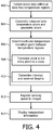
FIG. 4 , a method for determining a temperature transition point for deciphering a reference location is illustratively shown in accordance with one embodiment. Inblock 402, strain data is collected from a fiber optic strain sensing device disposed within at least two different temperature regions. The sensing device may include a first portion having a first temperature and a second portion having a second temperature, and the first portion is internal to a body, and the second portion is external to the body. In this instance, the transition point includes a point of entry in the body. In another example, the first portion may include a temperature treated zone (ablation zone, cryogenic treated zone, etc.), and the second portion includes a reference temperature zone. The transition point(s) may be employed to determine an entry/exit point to the body, determine a distance in the body to a target, determine an ablation region, etc. - The strain data may include geometrical data for determining a shape of a medical device as well as temperature transitions. In
block 404, the sensing data may include temperature induced strain and geometrically induced strain. The sensing device may include at least four optical fibers configured with three optical fibers surrounding a central optical fiber such that the three optical fibers measure geometric strain and the central optical fiber measures a temperature induced strain. Other configurations are also contemplated. - In
block 406, a temperature transition point is determined between the at least two different temperature regions based on the strain data. Any number of regions may be employed. Inblock 408, the transition point is located relative to a body and/or a medical device to find a specific reference location. Inblock 410, locating the transition point may include determining a length of the first portion and a length of the second portion. - In
block 412, an image of the body may be registered to temperature/shape sensing space using the temperature transition point as a reference. Inblock 414, temperature information is displayed. The transition point and/or the temperature gradient may be displayed for a clinician to improve accuracy, yield, etc. of a procedure. - In interpreting the appended claims, it should be understood that:
- a) the word "comprising" does not exclude the presence of other elements or acts than those listed in a given claim;
- b) the word "a" or "an" preceding an element does not exclude the presence of a plurality of such elements;
- c) any reference signs in the claims do not limit their scope;
- d) several "means" may be represented by the same item or hardware or software implemented structure or function; and
- e) no specific sequence of acts is intended to be required unless specifically indicated.
- Having described preferred embodiments for medical device insertion and exit information using distributed fiber optic temperature sensing (which are intended to be illustrative and not limiting), it is noted that modifications and variations can be made by persons skilled in the art in light of the above teachings. It is therefore to be understood that changes may be made in the particular embodiments of the disclosure disclosed which are within the scope of the embodiments disclosed herein as outlined by the appended claims.
Claims (14)
- A system, comprising:a sensing enabled device (102) having at least one optical fiber (126) configured to perform distributed sensing of temperature-induced strain and shape sensing of the device; characterized by an interpretation module (115) configured to receive optical signals from the at least one optical fiber within a body and interpret the optical signals to determine at least one temperature gradient of the device.
- The system as recited in claim 1, wherein the sensing enabled device (102) includes an elongated medical device.
- The system as recited in claim 1, wherein the interpretation module (115) is configured to determine a transition point between a first portion of the sensing enabled device having a first temperature and a second portion of the sensing enable device having a second temperature.
- The system as recited in claim 3, wherein the first portion (244) is internal to a body and the second portion (242) is external to the body and the transition point (208) is representative of a point of entry in the body.
- The system as recited in claim 3, wherein the interpretation module (115) is configured to determine a length of the first portion (244) and a length of the second portion (242).
- The system as recited in claim 1, wherein the sensing enabled device (102) includes four or more optical fibers configured with three or more optical fibers (302) surrounding a central optical fiber (304) such that the surrounding optical fibers measure geometric strain and the central optical fiber measures the temperature-induced strain.
- The system as recited in claim 1, further comprising an image generation module (148) configured to receive the at least one temperature gradient of the device and to register an image to a space of the sensing enabled device by using the at least one temperature gradient as reference.
- A workstation, comprising:the system as recited in claim 1;a medical instrument (102) including the sensing device (104) of the system;a processor (114);memory (116) coupled to the processor and having the interpretation module (115) of the system stored therein to determine at least one temperature gradient of the device in a subject; anda display (118) coupled to the processor and configured to display temperature gradient information relative to the subject.
- The workstation as recited in claim 8, wherein the medical instrument (102) includes an elongated device.
- The workstation as recited in claim 12, wherein interpretation module (115) is configured to determine a transition point between a first portion of the sensing device having a first temperature and a second portion of the sensing device having a second temperature.
- The workstation as recited in claim 10, wherein the first portion (244) is internal to a body and the second portion (242) is external to the body and the transition point (208) is representative of a point of entry in the body.
- The workstation as recited in claim 10, wherein the interpretation module (115) is configured to determine a length of the first portion and a length of the second portion.
- The workstation as recited in claim 8, wherein the sensing device (104) includes four or more optical fibers configured with three or more optical fibers (302) surrounding a central optical fiber (304) such that the surrounding optical fibers measure geometric strain and the central optical fiber measures the temperature-induced strain.
- The workstation as recited in claim 8, further comprising an image generation module (148) configured to receive the at least one temperature gradient of the device and to register an image to a space of the sensing device by using the at least one temperature gradient as reference.
Applications Claiming Priority (2)
| Application Number | Priority Date | Filing Date | Title |
|---|---|---|---|
| US201161530443P | 2011-09-02 | 2011-09-02 | |
| PCT/IB2012/054379 WO2013030749A2 (en) | 2011-09-02 | 2012-08-27 | Medical device insertion and exit information using distributed fiber optic temperature sensing |
Publications (2)
| Publication Number | Publication Date |
|---|---|
| EP2742329A2 EP2742329A2 (en) | 2014-06-18 |
| EP2742329B1 true EP2742329B1 (en) | 2017-12-27 |
Family
ID=47076296
Family Applications (1)
| Application Number | Title | Priority Date | Filing Date |
|---|---|---|---|
| EP12778422.1A Active EP2742329B1 (en) | 2011-09-02 | 2012-08-27 | Medical device insertion and exit information using distributed fiber optic temperature sensing |
Country Status (7)
| Country | Link |
|---|---|
| US (2) | US20140206988A1 (en) |
| EP (1) | EP2742329B1 (en) |
| JP (1) | JP6223977B2 (en) |
| CN (1) | CN103765176B (en) |
| MX (1) | MX342395B (en) |
| RU (1) | RU2628638C2 (en) |
| WO (1) | WO2013030749A2 (en) |
Families Citing this family (26)
| Publication number | Priority date | Publication date | Assignee | Title |
|---|---|---|---|---|
| WO2016037137A1 (en) * | 2014-09-05 | 2016-03-10 | Procept Biorobotics Corporation | Physician controlled tissue resection integrated with treatment mapping of target organ images |
| CN104349715B (en) * | 2012-06-08 | 2018-02-16 | 皇家飞利浦有限公司 | Distributed sensing equipment for the reference to physiological characteristic |
| WO2015092590A1 (en) * | 2013-12-17 | 2015-06-25 | Koninklijke Philips N.V. | System and method for determining the entry point to the body using optical shape sensing |
| WO2015128218A1 (en) * | 2014-02-27 | 2015-09-03 | Koninklijke Philips N.V. | System for performing a therapeutic procedure |
| EP3113702B1 (en) * | 2014-02-27 | 2021-03-10 | Koninklijke Philips N.V. | Registration apparatus for interventional procedure |
| JP6496403B2 (en) * | 2014-09-16 | 2019-04-03 | コーニンクレッカ フィリップス エヌ ヴェKoninklijke Philips N.V. | A processing system configured to cooperate with an optical shape sensitive interventional device |
| WO2016122742A2 (en) * | 2014-11-11 | 2016-08-04 | Luna Innovations Incorporated | Optical fiber and method and apparatus for accurate fiber optic sensing under multiple stimuli |
| JP6841757B2 (en) * | 2014-12-01 | 2021-03-10 | コーニンクレッカ フィリップス エヌ ヴェKoninklijke Philips N.V. | Alignment of optical shape sensing tools |
| WO2016116796A1 (en) * | 2015-01-22 | 2016-07-28 | Koninklijke Philips N.V. | Device visualization through optical shape sensing of a guidewire |
| EP3093043B1 (en) | 2015-05-13 | 2018-11-14 | Brainsgate Ltd. | Implant and delivery system for neural stimulator |
| WO2017176101A1 (en) * | 2016-04-05 | 2017-10-12 | Частное Учреждение "Назарбаев Университет Рисеч Энд Инновейшн Систем" | Method for distributed temperature sensing during thermal ablation of a tumour using a fibre optic temperature sensor with a linearly chirped bragg grating |
| JP7061114B6 (en) * | 2016-09-28 | 2022-06-03 | コーニンクレッカ フィリップス エヌ ヴェ | Blood flow measurement system |
| EP3639001A4 (en) | 2017-06-16 | 2021-03-10 | Saint-Gobain ADFORS Canada, Ltd. | Sensing textile |
| EP3743146A2 (en) * | 2018-01-22 | 2020-12-02 | Lakkireddy, Dhanunjaya | Esophageal management system for use in displacing an esophagus during a medical procedure |
| WO2020033947A1 (en) * | 2018-08-10 | 2020-02-13 | Covidien Lp | Systems for ablation visualization |
| US10799090B1 (en) | 2019-06-13 | 2020-10-13 | Verb Surgical Inc. | Method and system for automatically turning on/off a light source for an endoscope during a surgery |
| CN112386335A (en) | 2019-08-12 | 2021-02-23 | 巴德阿克塞斯系统股份有限公司 | Shape sensing systems and methods for medical devices |
| CN112826480A (en) | 2019-11-25 | 2021-05-25 | 巴德阿克塞斯系统股份有限公司 | Shape sensing system with filter and method thereof |
| EP4061466A4 (en) | 2019-11-25 | 2023-11-22 | Bard Access Systems, Inc. | Optical tip-tracking systems and methods thereof |
| EP4110175A1 (en) | 2020-02-28 | 2023-01-04 | Bard Access Systems, Inc. | Optical connection systems and methods thereof |
| WO2021202589A1 (en) | 2020-03-30 | 2021-10-07 | Bard Access Systems, Inc. | Optical and electrical diagnostic systems and methods thereof |
| EP4171423A1 (en) | 2020-06-26 | 2023-05-03 | Bard Access Systems, Inc. | Malposition detection system |
| CN113926050A (en) | 2020-06-29 | 2022-01-14 | 巴德阿克塞斯系统股份有限公司 | Automatic dimensional reference system for optical fibers |
| EP4178431A1 (en) | 2020-07-10 | 2023-05-17 | Bard Access Systems, Inc. | Continuous fiber optic functionality monitoring and self-diagnostic reporting system |
| WO2022031613A1 (en) | 2020-08-03 | 2022-02-10 | Bard Access Systems, Inc. | Bragg grated fiber optic fluctuation sensing and monitoring system |
| EP4229456A1 (en) | 2020-10-13 | 2023-08-23 | Bard Access Systems, Inc. | Disinfecting covers for functional connectors of medical devices and methods thereof |
Family Cites Families (24)
| Publication number | Priority date | Publication date | Assignee | Title |
|---|---|---|---|---|
| US5653539A (en) * | 1994-05-02 | 1997-08-05 | Rosengaus; Eliezer | Method and apparatus for remotely measuring the temperature of a surface |
| US5730134A (en) * | 1996-09-09 | 1998-03-24 | General Electric Company | System to monitor temperature near an invasive device during magnetic resonance procedures |
| BR0108473A (en) | 2000-02-17 | 2003-04-22 | Sallen Electronica | Document Handler, Document Operation Method, and Document Thickness Detector |
| AU2002337596A1 (en) * | 2001-09-27 | 2003-04-07 | Galil Medical Ltd. | Cryoplasty apparatus and method |
| US7297154B2 (en) * | 2003-02-24 | 2007-11-20 | Maxwell Sensors Inc. | Optical apparatus for detecting and treating vulnerable plaque |
| JP4554967B2 (en) * | 2004-03-25 | 2010-09-29 | テルモ株式会社 | Ultrasonic catheter and diagnostic imaging apparatus |
| US8894589B2 (en) * | 2005-08-01 | 2014-11-25 | Endosense Sa | Medical apparatus system having optical fiber load sensing capability |
| US7930065B2 (en) * | 2005-12-30 | 2011-04-19 | Intuitive Surgical Operations, Inc. | Robotic surgery system including position sensors using fiber bragg gratings |
| US7717618B2 (en) * | 2005-12-30 | 2010-05-18 | Optech Ventures, Llc | Apparatus and method for high resolution temperature measurement and for hyperthermia therapy |
| JP2008173397A (en) * | 2007-01-22 | 2008-07-31 | Olympus Corp | Endoscope system |
| US7976537B2 (en) * | 2007-06-28 | 2011-07-12 | Biosense Webster, Inc. | Optical pyrometric catheter for tissue temperature monitoring during cardiac ablation |
| CN101099657A (en) * | 2007-07-13 | 2008-01-09 | 上海大学 | Thin long flexible rod spatial shape detecting device and method |
| US20130165945A9 (en) * | 2007-08-14 | 2013-06-27 | Hansen Medical, Inc. | Methods and devices for controlling a shapeable instrument |
| AU2008310799A1 (en) * | 2007-10-11 | 2009-04-16 | Tufts University | Systems, devices, and methods employing fiber optic shape tracking |
| US8009946B2 (en) | 2008-01-22 | 2011-08-30 | General Electric Company | Fiberoptic patient health multi-parameter monitoring devices and system |
| WO2009111827A1 (en) * | 2008-03-11 | 2009-09-17 | Commonwealth Scientific And Industrial Research Organisation | An optical device |
| JP2011517417A (en) | 2008-03-18 | 2011-06-09 | サーカ・サイエンティフィック,エルエルシー | Large surface area temperature sensing device |
| DE102008014745A1 (en) * | 2008-03-18 | 2009-10-01 | Siemens Aktiengesellschaft | Tank monitoring device on a ship |
| US8298227B2 (en) * | 2008-05-14 | 2012-10-30 | Endosense Sa | Temperature compensated strain sensing catheter |
| CA2839071C (en) * | 2009-03-04 | 2017-10-17 | Imricor Medical Systems, Inc. | Mri compatible medical device temperature monitoring system and method |
| RU87081U1 (en) * | 2009-05-12 | 2009-09-27 | Учреждение Российской академии наук Институт радиотехники и электроники им. В.А. Котельникова РАН | LASER CATHETER WITH FIBER OPTICAL SENSOR |
| JP5388732B2 (en) * | 2009-07-15 | 2014-01-15 | Hoya株式会社 | Medical observation system and processor |
| US8773650B2 (en) * | 2009-09-18 | 2014-07-08 | Intuitive Surgical Operations, Inc. | Optical position and/or shape sensing |
| JP5952736B2 (en) * | 2009-10-23 | 2016-07-13 | コーニンクレッカ フィリップス エヌ ヴェKoninklijke Philips N.V. | Light-sensitive interventional instrument for rapid dispersion measurement of biophysical parameters |
-
2012
- 2012-08-27 WO PCT/IB2012/054379 patent/WO2013030749A2/en active Application Filing
- 2012-08-27 EP EP12778422.1A patent/EP2742329B1/en active Active
- 2012-08-27 RU RU2014112712A patent/RU2628638C2/en active
- 2012-08-27 US US14/240,032 patent/US20140206988A1/en not_active Abandoned
- 2012-08-27 JP JP2014527779A patent/JP6223977B2/en active Active
- 2012-08-27 MX MX2014002198A patent/MX342395B/en active IP Right Grant
- 2012-08-27 CN CN201280042668.1A patent/CN103765176B/en active Active
-
2018
- 2018-10-31 US US16/175,887 patent/US11642031B2/en active Active
Also Published As
| Publication number | Publication date |
|---|---|
| CN103765176A (en) | 2014-04-30 |
| RU2628638C2 (en) | 2017-08-21 |
| US20190059743A1 (en) | 2019-02-28 |
| WO2013030749A3 (en) | 2016-01-07 |
| JP2014534826A (en) | 2014-12-25 |
| US11642031B2 (en) | 2023-05-09 |
| WO2013030749A2 (en) | 2013-03-07 |
| CN103765176B (en) | 2016-08-17 |
| RU2014112712A (en) | 2015-10-10 |
| EP2742329A2 (en) | 2014-06-18 |
| US20140206988A1 (en) | 2014-07-24 |
| MX342395B (en) | 2016-09-28 |
| JP6223977B2 (en) | 2017-11-01 |
| MX2014002198A (en) | 2014-06-04 |
Similar Documents
| Publication | Publication Date | Title |
|---|---|---|
| US11642031B2 (en) | Medical device insertion and exit information using distributed fiber optic temperature sensing | |
| US11206999B2 (en) | Flexible instrument channel insert for scope with real-time position tracking | |
| US11547489B2 (en) | Shape sensing of multiple over-the-wire devices | |
| US9693707B2 (en) | Optical shape sensing fiber for tip and shape characterization of medical instruments | |
| US9607381B2 (en) | Accurate and rapid mapping of points from ultrasound images to tracking systems | |
| US20130325387A1 (en) | Shape sensing device-specific | |
| US20150141764A1 (en) | Distributed sensing device for referencing of physiological features | |
| US20130301031A1 (en) | Templates for optical shape sensing calibration during clinical use | |
| US11344222B2 (en) | Systems and methods for determining the position of a non-shape-sensed guidewire with a shape-sensed catheter and for visualizing the guidewire | |
| US20180344204A1 (en) | Features for optical shape sense enabled device identification | |
| WO2012143883A2 (en) | Visible optical fiber for medical imaging applications | |
| WO2015092590A1 (en) | System and method for determining the entry point to the body using optical shape sensing |
Legal Events
| Date | Code | Title | Description |
|---|---|---|---|
| PUAI | Public reference made under article 153(3) epc to a published international application that has entered the european phase |
Free format text: ORIGINAL CODE: 0009012 |
|
| 17P | Request for examination filed |
Effective date: 20140314 |
|
| AK | Designated contracting states |
Kind code of ref document: A2 Designated state(s): AL AT BE BG CH CY CZ DE DK EE ES FI FR GB GR HR HU IE IS IT LI LT LU LV MC MK MT NL NO PL PT RO RS SE SI SK SM TR |
|
| DAX | Request for extension of the european patent (deleted) | ||
| R17D | Deferred search report published (corrected) |
Effective date: 20160107 |
|
| REG | Reference to a national code |
Ref country code: DE Ref legal event code: R079 Ref document number: 602012041399 Country of ref document: DE Free format text: PREVIOUS MAIN CLASS: G01K0003140000 Ipc: G01L0001240000 |
|
| GRAP | Despatch of communication of intention to grant a patent |
Free format text: ORIGINAL CODE: EPIDOSNIGR1 |
|
| RIC1 | Information provided on ipc code assigned before grant |
Ipc: A61B 5/01 20060101ALI20170531BHEP Ipc: G01K 3/14 20060101ALI20170531BHEP Ipc: G01K 11/32 20060101ALI20170531BHEP Ipc: G01L 1/24 20060101AFI20170531BHEP Ipc: A61B 5/00 20060101ALI20170531BHEP Ipc: A61B 5/06 20060101ALI20170531BHEP |
|
| INTG | Intention to grant announced |
Effective date: 20170704 |
|
| GRAS | Grant fee paid |
Free format text: ORIGINAL CODE: EPIDOSNIGR3 |
|
| GRAA | (expected) grant |
Free format text: ORIGINAL CODE: 0009210 |
|
| AK | Designated contracting states |
Kind code of ref document: B1 Designated state(s): AL AT BE BG CH CY CZ DE DK EE ES FI FR GB GR HR HU IE IS IT LI LT LU LV MC MK MT NL NO PL PT RO RS SE SI SK SM TR |
|
| REG | Reference to a national code |
Ref country code: GB Ref legal event code: FG4D |
|
| REG | Reference to a national code |
Ref country code: CH Ref legal event code: EP |
|
| REG | Reference to a national code |
Ref country code: AT Ref legal event code: REF Ref document number: 958699 Country of ref document: AT Kind code of ref document: T Effective date: 20180115 |
|
| REG | Reference to a national code |
Ref country code: IE Ref legal event code: FG4D |
|
| REG | Reference to a national code |
Ref country code: DE Ref legal event code: R096 Ref document number: 602012041399 Country of ref document: DE |
|
| PG25 | Lapsed in a contracting state [announced via postgrant information from national office to epo] |
Ref country code: FI Free format text: LAPSE BECAUSE OF FAILURE TO SUBMIT A TRANSLATION OF THE DESCRIPTION OR TO PAY THE FEE WITHIN THE PRESCRIBED TIME-LIMIT Effective date: 20171227 Ref country code: LT Free format text: LAPSE BECAUSE OF FAILURE TO SUBMIT A TRANSLATION OF THE DESCRIPTION OR TO PAY THE FEE WITHIN THE PRESCRIBED TIME-LIMIT Effective date: 20171227 Ref country code: NO Free format text: LAPSE BECAUSE OF FAILURE TO SUBMIT A TRANSLATION OF THE DESCRIPTION OR TO PAY THE FEE WITHIN THE PRESCRIBED TIME-LIMIT Effective date: 20180327 |
|
| REG | Reference to a national code |
Ref country code: NL Ref legal event code: MP Effective date: 20171227 |
|
| REG | Reference to a national code |
Ref country code: LT Ref legal event code: MG4D |
|
| REG | Reference to a national code |
Ref country code: AT Ref legal event code: MK05 Ref document number: 958699 Country of ref document: AT Kind code of ref document: T Effective date: 20171227 |
|
| PG25 | Lapsed in a contracting state [announced via postgrant information from national office to epo] |
Ref country code: RS Free format text: LAPSE BECAUSE OF FAILURE TO SUBMIT A TRANSLATION OF THE DESCRIPTION OR TO PAY THE FEE WITHIN THE PRESCRIBED TIME-LIMIT Effective date: 20171227 Ref country code: LV Free format text: LAPSE BECAUSE OF FAILURE TO SUBMIT A TRANSLATION OF THE DESCRIPTION OR TO PAY THE FEE WITHIN THE PRESCRIBED TIME-LIMIT Effective date: 20171227 Ref country code: HR Free format text: LAPSE BECAUSE OF FAILURE TO SUBMIT A TRANSLATION OF THE DESCRIPTION OR TO PAY THE FEE WITHIN THE PRESCRIBED TIME-LIMIT Effective date: 20171227 Ref country code: GR Free format text: LAPSE BECAUSE OF FAILURE TO SUBMIT A TRANSLATION OF THE DESCRIPTION OR TO PAY THE FEE WITHIN THE PRESCRIBED TIME-LIMIT Effective date: 20180328 Ref country code: BG Free format text: LAPSE BECAUSE OF FAILURE TO SUBMIT A TRANSLATION OF THE DESCRIPTION OR TO PAY THE FEE WITHIN THE PRESCRIBED TIME-LIMIT Effective date: 20180327 |
|
| PG25 | Lapsed in a contracting state [announced via postgrant information from national office to epo] |
Ref country code: NL Free format text: LAPSE BECAUSE OF FAILURE TO SUBMIT A TRANSLATION OF THE DESCRIPTION OR TO PAY THE FEE WITHIN THE PRESCRIBED TIME-LIMIT Effective date: 20171227 |
|
| PG25 | Lapsed in a contracting state [announced via postgrant information from national office to epo] |
Ref country code: SK Free format text: LAPSE BECAUSE OF FAILURE TO SUBMIT A TRANSLATION OF THE DESCRIPTION OR TO PAY THE FEE WITHIN THE PRESCRIBED TIME-LIMIT Effective date: 20171227 Ref country code: CY Free format text: LAPSE BECAUSE OF FAILURE TO SUBMIT A TRANSLATION OF THE DESCRIPTION OR TO PAY THE FEE WITHIN THE PRESCRIBED TIME-LIMIT Effective date: 20171227 Ref country code: CZ Free format text: LAPSE BECAUSE OF FAILURE TO SUBMIT A TRANSLATION OF THE DESCRIPTION OR TO PAY THE FEE WITHIN THE PRESCRIBED TIME-LIMIT Effective date: 20171227 Ref country code: ES Free format text: LAPSE BECAUSE OF FAILURE TO SUBMIT A TRANSLATION OF THE DESCRIPTION OR TO PAY THE FEE WITHIN THE PRESCRIBED TIME-LIMIT Effective date: 20171227 Ref country code: EE Free format text: LAPSE BECAUSE OF FAILURE TO SUBMIT A TRANSLATION OF THE DESCRIPTION OR TO PAY THE FEE WITHIN THE PRESCRIBED TIME-LIMIT Effective date: 20171227 |
|
| REG | Reference to a national code |
Ref country code: FR Ref legal event code: PLFP Year of fee payment: 7 |
|
| PG25 | Lapsed in a contracting state [announced via postgrant information from national office to epo] |
Ref country code: SM Free format text: LAPSE BECAUSE OF FAILURE TO SUBMIT A TRANSLATION OF THE DESCRIPTION OR TO PAY THE FEE WITHIN THE PRESCRIBED TIME-LIMIT Effective date: 20171227 Ref country code: IS Free format text: LAPSE BECAUSE OF FAILURE TO SUBMIT A TRANSLATION OF THE DESCRIPTION OR TO PAY THE FEE WITHIN THE PRESCRIBED TIME-LIMIT Effective date: 20180427 Ref country code: PL Free format text: LAPSE BECAUSE OF FAILURE TO SUBMIT A TRANSLATION OF THE DESCRIPTION OR TO PAY THE FEE WITHIN THE PRESCRIBED TIME-LIMIT Effective date: 20171227 Ref country code: RO Free format text: LAPSE BECAUSE OF FAILURE TO SUBMIT A TRANSLATION OF THE DESCRIPTION OR TO PAY THE FEE WITHIN THE PRESCRIBED TIME-LIMIT Effective date: 20171227 Ref country code: AT Free format text: LAPSE BECAUSE OF FAILURE TO SUBMIT A TRANSLATION OF THE DESCRIPTION OR TO PAY THE FEE WITHIN THE PRESCRIBED TIME-LIMIT Effective date: 20171227 Ref country code: IT Free format text: LAPSE BECAUSE OF FAILURE TO SUBMIT A TRANSLATION OF THE DESCRIPTION OR TO PAY THE FEE WITHIN THE PRESCRIBED TIME-LIMIT Effective date: 20171227 |
|
| REG | Reference to a national code |
Ref country code: DE Ref legal event code: R097 Ref document number: 602012041399 Country of ref document: DE |
|
| PLBE | No opposition filed within time limit |
Free format text: ORIGINAL CODE: 0009261 |
|
| STAA | Information on the status of an ep patent application or granted ep patent |
Free format text: STATUS: NO OPPOSITION FILED WITHIN TIME LIMIT |
|
| PG25 | Lapsed in a contracting state [announced via postgrant information from national office to epo] |
Ref country code: DK Free format text: LAPSE BECAUSE OF FAILURE TO SUBMIT A TRANSLATION OF THE DESCRIPTION OR TO PAY THE FEE WITHIN THE PRESCRIBED TIME-LIMIT Effective date: 20171227 |
|
| 26N | No opposition filed |
Effective date: 20180928 |
|
| PG25 | Lapsed in a contracting state [announced via postgrant information from national office to epo] |
Ref country code: SI Free format text: LAPSE BECAUSE OF FAILURE TO SUBMIT A TRANSLATION OF THE DESCRIPTION OR TO PAY THE FEE WITHIN THE PRESCRIBED TIME-LIMIT Effective date: 20171227 |
|
| PG25 | Lapsed in a contracting state [announced via postgrant information from national office to epo] |
Ref country code: MC Free format text: LAPSE BECAUSE OF FAILURE TO SUBMIT A TRANSLATION OF THE DESCRIPTION OR TO PAY THE FEE WITHIN THE PRESCRIBED TIME-LIMIT Effective date: 20171227 |
|
| REG | Reference to a national code |
Ref country code: CH Ref legal event code: PL |
|
| PG25 | Lapsed in a contracting state [announced via postgrant information from national office to epo] |
Ref country code: CH Free format text: LAPSE BECAUSE OF NON-PAYMENT OF DUE FEES Effective date: 20180831 Ref country code: LU Free format text: LAPSE BECAUSE OF NON-PAYMENT OF DUE FEES Effective date: 20180827 Ref country code: LI Free format text: LAPSE BECAUSE OF NON-PAYMENT OF DUE FEES Effective date: 20180831 |
|
| REG | Reference to a national code |
Ref country code: BE Ref legal event code: MM Effective date: 20180831 |
|
| PG25 | Lapsed in a contracting state [announced via postgrant information from national office to epo] |
Ref country code: BE Free format text: LAPSE BECAUSE OF NON-PAYMENT OF DUE FEES Effective date: 20180831 |
|
| PG25 | Lapsed in a contracting state [announced via postgrant information from national office to epo] |
Ref country code: MT Free format text: LAPSE BECAUSE OF NON-PAYMENT OF DUE FEES Effective date: 20180827 |
|
| PG25 | Lapsed in a contracting state [announced via postgrant information from national office to epo] |
Ref country code: TR Free format text: LAPSE BECAUSE OF FAILURE TO SUBMIT A TRANSLATION OF THE DESCRIPTION OR TO PAY THE FEE WITHIN THE PRESCRIBED TIME-LIMIT Effective date: 20171227 |
|
| PG25 | Lapsed in a contracting state [announced via postgrant information from national office to epo] |
Ref country code: PT Free format text: LAPSE BECAUSE OF FAILURE TO SUBMIT A TRANSLATION OF THE DESCRIPTION OR TO PAY THE FEE WITHIN THE PRESCRIBED TIME-LIMIT Effective date: 20171227 Ref country code: HU Free format text: LAPSE BECAUSE OF FAILURE TO SUBMIT A TRANSLATION OF THE DESCRIPTION OR TO PAY THE FEE WITHIN THE PRESCRIBED TIME-LIMIT; INVALID AB INITIO Effective date: 20120827 |
|
| PG25 | Lapsed in a contracting state [announced via postgrant information from national office to epo] |
Ref country code: IE Free format text: LAPSE BECAUSE OF NON-PAYMENT OF DUE FEES Effective date: 20180827 Ref country code: MK Free format text: LAPSE BECAUSE OF NON-PAYMENT OF DUE FEES Effective date: 20171227 Ref country code: SE Free format text: LAPSE BECAUSE OF FAILURE TO SUBMIT A TRANSLATION OF THE DESCRIPTION OR TO PAY THE FEE WITHIN THE PRESCRIBED TIME-LIMIT Effective date: 20171227 |
|
| PG25 | Lapsed in a contracting state [announced via postgrant information from national office to epo] |
Ref country code: AL Free format text: LAPSE BECAUSE OF FAILURE TO SUBMIT A TRANSLATION OF THE DESCRIPTION OR TO PAY THE FEE WITHIN THE PRESCRIBED TIME-LIMIT Effective date: 20171227 |
|
| PGFP | Annual fee paid to national office [announced via postgrant information from national office to epo] |
Ref country code: GB Payment date: 20230822 Year of fee payment: 12 |
|
| PGFP | Annual fee paid to national office [announced via postgrant information from national office to epo] |
Ref country code: FR Payment date: 20230824 Year of fee payment: 12 Ref country code: DE Payment date: 20230828 Year of fee payment: 12 |