JP6496163B2 - Hybrid construction machine - Google Patents
Hybrid construction machine Download PDFInfo
- Publication number
- JP6496163B2 JP6496163B2 JP2015040875A JP2015040875A JP6496163B2 JP 6496163 B2 JP6496163 B2 JP 6496163B2 JP 2015040875 A JP2015040875 A JP 2015040875A JP 2015040875 A JP2015040875 A JP 2015040875A JP 6496163 B2 JP6496163 B2 JP 6496163B2
- Authority
- JP
- Japan
- Prior art keywords
- warm
- storage device
- power storage
- temperature
- construction machine
- Prior art date
- Legal status (The legal status is an assumption and is not a legal conclusion. Google has not performed a legal analysis and makes no representation as to the accuracy of the status listed.)
- Active
Links
Images


Classifications
-
- B—PERFORMING OPERATIONS; TRANSPORTING
- B60—VEHICLES IN GENERAL
- B60L—PROPULSION OF ELECTRICALLY-PROPELLED VEHICLES; SUPPLYING ELECTRIC POWER FOR AUXILIARY EQUIPMENT OF ELECTRICALLY-PROPELLED VEHICLES; ELECTRODYNAMIC BRAKE SYSTEMS FOR VEHICLES IN GENERAL; MAGNETIC SUSPENSION OR LEVITATION FOR VEHICLES; MONITORING OPERATING VARIABLES OF ELECTRICALLY-PROPELLED VEHICLES; ELECTRIC SAFETY DEVICES FOR ELECTRICALLY-PROPELLED VEHICLES
- B60L58/00—Methods or circuit arrangements for monitoring or controlling batteries or fuel cells, specially adapted for electric vehicles
- B60L58/10—Methods or circuit arrangements for monitoring or controlling batteries or fuel cells, specially adapted for electric vehicles for monitoring or controlling batteries
- B60L58/24—Methods or circuit arrangements for monitoring or controlling batteries or fuel cells, specially adapted for electric vehicles for monitoring or controlling batteries for controlling the temperature of batteries
- B60L58/27—Methods or circuit arrangements for monitoring or controlling batteries or fuel cells, specially adapted for electric vehicles for monitoring or controlling batteries for controlling the temperature of batteries by heating
-
- B—PERFORMING OPERATIONS; TRANSPORTING
- B60—VEHICLES IN GENERAL
- B60K—ARRANGEMENT OR MOUNTING OF PROPULSION UNITS OR OF TRANSMISSIONS IN VEHICLES; ARRANGEMENT OR MOUNTING OF PLURAL DIVERSE PRIME-MOVERS IN VEHICLES; AUXILIARY DRIVES FOR VEHICLES; INSTRUMENTATION OR DASHBOARDS FOR VEHICLES; ARRANGEMENTS IN CONNECTION WITH COOLING, AIR INTAKE, GAS EXHAUST OR FUEL SUPPLY OF PROPULSION UNITS IN VEHICLES
- B60K6/00—Arrangement or mounting of plural diverse prime-movers for mutual or common propulsion, e.g. hybrid propulsion systems comprising electric motors and internal combustion engines ; Control systems therefor, i.e. systems controlling two or more prime movers, or controlling one of these prime movers and any of the transmission, drive or drive units Informative references: mechanical gearings with secondary electric drive F16H3/72; arrangements for handling mechanical energy structurally associated with the dynamo-electric machine H02K7/00; machines comprising structurally interrelated motor and generator parts H02K51/00; dynamo-electric machines not otherwise provided for in H02K see H02K99/00
- B60K6/20—Arrangement or mounting of plural diverse prime-movers for mutual or common propulsion, e.g. hybrid propulsion systems comprising electric motors and internal combustion engines ; Control systems therefor, i.e. systems controlling two or more prime movers, or controlling one of these prime movers and any of the transmission, drive or drive units Informative references: mechanical gearings with secondary electric drive F16H3/72; arrangements for handling mechanical energy structurally associated with the dynamo-electric machine H02K7/00; machines comprising structurally interrelated motor and generator parts H02K51/00; dynamo-electric machines not otherwise provided for in H02K see H02K99/00 the prime-movers consisting of electric motors and internal combustion engines, e.g. HEVs
- B60K6/42—Arrangement or mounting of plural diverse prime-movers for mutual or common propulsion, e.g. hybrid propulsion systems comprising electric motors and internal combustion engines ; Control systems therefor, i.e. systems controlling two or more prime movers, or controlling one of these prime movers and any of the transmission, drive or drive units Informative references: mechanical gearings with secondary electric drive F16H3/72; arrangements for handling mechanical energy structurally associated with the dynamo-electric machine H02K7/00; machines comprising structurally interrelated motor and generator parts H02K51/00; dynamo-electric machines not otherwise provided for in H02K see H02K99/00 the prime-movers consisting of electric motors and internal combustion engines, e.g. HEVs characterised by the architecture of the hybrid electric vehicle
- B60K6/48—Parallel type
- B60K6/485—Motor-assist type
-
- B—PERFORMING OPERATIONS; TRANSPORTING
- B60—VEHICLES IN GENERAL
- B60K—ARRANGEMENT OR MOUNTING OF PROPULSION UNITS OR OF TRANSMISSIONS IN VEHICLES; ARRANGEMENT OR MOUNTING OF PLURAL DIVERSE PRIME-MOVERS IN VEHICLES; AUXILIARY DRIVES FOR VEHICLES; INSTRUMENTATION OR DASHBOARDS FOR VEHICLES; ARRANGEMENTS IN CONNECTION WITH COOLING, AIR INTAKE, GAS EXHAUST OR FUEL SUPPLY OF PROPULSION UNITS IN VEHICLES
- B60K6/00—Arrangement or mounting of plural diverse prime-movers for mutual or common propulsion, e.g. hybrid propulsion systems comprising electric motors and internal combustion engines ; Control systems therefor, i.e. systems controlling two or more prime movers, or controlling one of these prime movers and any of the transmission, drive or drive units Informative references: mechanical gearings with secondary electric drive F16H3/72; arrangements for handling mechanical energy structurally associated with the dynamo-electric machine H02K7/00; machines comprising structurally interrelated motor and generator parts H02K51/00; dynamo-electric machines not otherwise provided for in H02K see H02K99/00
- B60K6/20—Arrangement or mounting of plural diverse prime-movers for mutual or common propulsion, e.g. hybrid propulsion systems comprising electric motors and internal combustion engines ; Control systems therefor, i.e. systems controlling two or more prime movers, or controlling one of these prime movers and any of the transmission, drive or drive units Informative references: mechanical gearings with secondary electric drive F16H3/72; arrangements for handling mechanical energy structurally associated with the dynamo-electric machine H02K7/00; machines comprising structurally interrelated motor and generator parts H02K51/00; dynamo-electric machines not otherwise provided for in H02K see H02K99/00 the prime-movers consisting of electric motors and internal combustion engines, e.g. HEVs
- B60K6/22—Arrangement or mounting of plural diverse prime-movers for mutual or common propulsion, e.g. hybrid propulsion systems comprising electric motors and internal combustion engines ; Control systems therefor, i.e. systems controlling two or more prime movers, or controlling one of these prime movers and any of the transmission, drive or drive units Informative references: mechanical gearings with secondary electric drive F16H3/72; arrangements for handling mechanical energy structurally associated with the dynamo-electric machine H02K7/00; machines comprising structurally interrelated motor and generator parts H02K51/00; dynamo-electric machines not otherwise provided for in H02K see H02K99/00 the prime-movers consisting of electric motors and internal combustion engines, e.g. HEVs characterised by apparatus, components or means specially adapted for HEVs
- B60K6/24—Arrangement or mounting of plural diverse prime-movers for mutual or common propulsion, e.g. hybrid propulsion systems comprising electric motors and internal combustion engines ; Control systems therefor, i.e. systems controlling two or more prime movers, or controlling one of these prime movers and any of the transmission, drive or drive units Informative references: mechanical gearings with secondary electric drive F16H3/72; arrangements for handling mechanical energy structurally associated with the dynamo-electric machine H02K7/00; machines comprising structurally interrelated motor and generator parts H02K51/00; dynamo-electric machines not otherwise provided for in H02K see H02K99/00 the prime-movers consisting of electric motors and internal combustion engines, e.g. HEVs characterised by apparatus, components or means specially adapted for HEVs characterised by the combustion engines
-
- B—PERFORMING OPERATIONS; TRANSPORTING
- B60—VEHICLES IN GENERAL
- B60K—ARRANGEMENT OR MOUNTING OF PROPULSION UNITS OR OF TRANSMISSIONS IN VEHICLES; ARRANGEMENT OR MOUNTING OF PLURAL DIVERSE PRIME-MOVERS IN VEHICLES; AUXILIARY DRIVES FOR VEHICLES; INSTRUMENTATION OR DASHBOARDS FOR VEHICLES; ARRANGEMENTS IN CONNECTION WITH COOLING, AIR INTAKE, GAS EXHAUST OR FUEL SUPPLY OF PROPULSION UNITS IN VEHICLES
- B60K6/00—Arrangement or mounting of plural diverse prime-movers for mutual or common propulsion, e.g. hybrid propulsion systems comprising electric motors and internal combustion engines ; Control systems therefor, i.e. systems controlling two or more prime movers, or controlling one of these prime movers and any of the transmission, drive or drive units Informative references: mechanical gearings with secondary electric drive F16H3/72; arrangements for handling mechanical energy structurally associated with the dynamo-electric machine H02K7/00; machines comprising structurally interrelated motor and generator parts H02K51/00; dynamo-electric machines not otherwise provided for in H02K see H02K99/00
- B60K6/20—Arrangement or mounting of plural diverse prime-movers for mutual or common propulsion, e.g. hybrid propulsion systems comprising electric motors and internal combustion engines ; Control systems therefor, i.e. systems controlling two or more prime movers, or controlling one of these prime movers and any of the transmission, drive or drive units Informative references: mechanical gearings with secondary electric drive F16H3/72; arrangements for handling mechanical energy structurally associated with the dynamo-electric machine H02K7/00; machines comprising structurally interrelated motor and generator parts H02K51/00; dynamo-electric machines not otherwise provided for in H02K see H02K99/00 the prime-movers consisting of electric motors and internal combustion engines, e.g. HEVs
- B60K6/22—Arrangement or mounting of plural diverse prime-movers for mutual or common propulsion, e.g. hybrid propulsion systems comprising electric motors and internal combustion engines ; Control systems therefor, i.e. systems controlling two or more prime movers, or controlling one of these prime movers and any of the transmission, drive or drive units Informative references: mechanical gearings with secondary electric drive F16H3/72; arrangements for handling mechanical energy structurally associated with the dynamo-electric machine H02K7/00; machines comprising structurally interrelated motor and generator parts H02K51/00; dynamo-electric machines not otherwise provided for in H02K see H02K99/00 the prime-movers consisting of electric motors and internal combustion engines, e.g. HEVs characterised by apparatus, components or means specially adapted for HEVs
- B60K6/26—Arrangement or mounting of plural diverse prime-movers for mutual or common propulsion, e.g. hybrid propulsion systems comprising electric motors and internal combustion engines ; Control systems therefor, i.e. systems controlling two or more prime movers, or controlling one of these prime movers and any of the transmission, drive or drive units Informative references: mechanical gearings with secondary electric drive F16H3/72; arrangements for handling mechanical energy structurally associated with the dynamo-electric machine H02K7/00; machines comprising structurally interrelated motor and generator parts H02K51/00; dynamo-electric machines not otherwise provided for in H02K see H02K99/00 the prime-movers consisting of electric motors and internal combustion engines, e.g. HEVs characterised by apparatus, components or means specially adapted for HEVs characterised by the motors or the generators
-
- B—PERFORMING OPERATIONS; TRANSPORTING
- B60—VEHICLES IN GENERAL
- B60K—ARRANGEMENT OR MOUNTING OF PROPULSION UNITS OR OF TRANSMISSIONS IN VEHICLES; ARRANGEMENT OR MOUNTING OF PLURAL DIVERSE PRIME-MOVERS IN VEHICLES; AUXILIARY DRIVES FOR VEHICLES; INSTRUMENTATION OR DASHBOARDS FOR VEHICLES; ARRANGEMENTS IN CONNECTION WITH COOLING, AIR INTAKE, GAS EXHAUST OR FUEL SUPPLY OF PROPULSION UNITS IN VEHICLES
- B60K6/00—Arrangement or mounting of plural diverse prime-movers for mutual or common propulsion, e.g. hybrid propulsion systems comprising electric motors and internal combustion engines ; Control systems therefor, i.e. systems controlling two or more prime movers, or controlling one of these prime movers and any of the transmission, drive or drive units Informative references: mechanical gearings with secondary electric drive F16H3/72; arrangements for handling mechanical energy structurally associated with the dynamo-electric machine H02K7/00; machines comprising structurally interrelated motor and generator parts H02K51/00; dynamo-electric machines not otherwise provided for in H02K see H02K99/00
- B60K6/20—Arrangement or mounting of plural diverse prime-movers for mutual or common propulsion, e.g. hybrid propulsion systems comprising electric motors and internal combustion engines ; Control systems therefor, i.e. systems controlling two or more prime movers, or controlling one of these prime movers and any of the transmission, drive or drive units Informative references: mechanical gearings with secondary electric drive F16H3/72; arrangements for handling mechanical energy structurally associated with the dynamo-electric machine H02K7/00; machines comprising structurally interrelated motor and generator parts H02K51/00; dynamo-electric machines not otherwise provided for in H02K see H02K99/00 the prime-movers consisting of electric motors and internal combustion engines, e.g. HEVs
- B60K6/22—Arrangement or mounting of plural diverse prime-movers for mutual or common propulsion, e.g. hybrid propulsion systems comprising electric motors and internal combustion engines ; Control systems therefor, i.e. systems controlling two or more prime movers, or controlling one of these prime movers and any of the transmission, drive or drive units Informative references: mechanical gearings with secondary electric drive F16H3/72; arrangements for handling mechanical energy structurally associated with the dynamo-electric machine H02K7/00; machines comprising structurally interrelated motor and generator parts H02K51/00; dynamo-electric machines not otherwise provided for in H02K see H02K99/00 the prime-movers consisting of electric motors and internal combustion engines, e.g. HEVs characterised by apparatus, components or means specially adapted for HEVs
- B60K6/28—Arrangement or mounting of plural diverse prime-movers for mutual or common propulsion, e.g. hybrid propulsion systems comprising electric motors and internal combustion engines ; Control systems therefor, i.e. systems controlling two or more prime movers, or controlling one of these prime movers and any of the transmission, drive or drive units Informative references: mechanical gearings with secondary electric drive F16H3/72; arrangements for handling mechanical energy structurally associated with the dynamo-electric machine H02K7/00; machines comprising structurally interrelated motor and generator parts H02K51/00; dynamo-electric machines not otherwise provided for in H02K see H02K99/00 the prime-movers consisting of electric motors and internal combustion engines, e.g. HEVs characterised by apparatus, components or means specially adapted for HEVs characterised by the electric energy storing means, e.g. batteries or capacitors
-
- B—PERFORMING OPERATIONS; TRANSPORTING
- B60—VEHICLES IN GENERAL
- B60L—PROPULSION OF ELECTRICALLY-PROPELLED VEHICLES; SUPPLYING ELECTRIC POWER FOR AUXILIARY EQUIPMENT OF ELECTRICALLY-PROPELLED VEHICLES; ELECTRODYNAMIC BRAKE SYSTEMS FOR VEHICLES IN GENERAL; MAGNETIC SUSPENSION OR LEVITATION FOR VEHICLES; MONITORING OPERATING VARIABLES OF ELECTRICALLY-PROPELLED VEHICLES; ELECTRIC SAFETY DEVICES FOR ELECTRICALLY-PROPELLED VEHICLES
- B60L3/00—Electric devices on electrically-propelled vehicles for safety purposes; Monitoring operating variables, e.g. speed, deceleration or energy consumption
- B60L3/0023—Detecting, eliminating, remedying or compensating for drive train abnormalities, e.g. failures within the drive train
- B60L3/0046—Detecting, eliminating, remedying or compensating for drive train abnormalities, e.g. failures within the drive train relating to electric energy storage systems, e.g. batteries or capacitors
-
- B—PERFORMING OPERATIONS; TRANSPORTING
- B60—VEHICLES IN GENERAL
- B60L—PROPULSION OF ELECTRICALLY-PROPELLED VEHICLES; SUPPLYING ELECTRIC POWER FOR AUXILIARY EQUIPMENT OF ELECTRICALLY-PROPELLED VEHICLES; ELECTRODYNAMIC BRAKE SYSTEMS FOR VEHICLES IN GENERAL; MAGNETIC SUSPENSION OR LEVITATION FOR VEHICLES; MONITORING OPERATING VARIABLES OF ELECTRICALLY-PROPELLED VEHICLES; ELECTRIC SAFETY DEVICES FOR ELECTRICALLY-PROPELLED VEHICLES
- B60L58/00—Methods or circuit arrangements for monitoring or controlling batteries or fuel cells, specially adapted for electric vehicles
- B60L58/10—Methods or circuit arrangements for monitoring or controlling batteries or fuel cells, specially adapted for electric vehicles for monitoring or controlling batteries
- B60L58/24—Methods or circuit arrangements for monitoring or controlling batteries or fuel cells, specially adapted for electric vehicles for monitoring or controlling batteries for controlling the temperature of batteries
- B60L58/25—Methods or circuit arrangements for monitoring or controlling batteries or fuel cells, specially adapted for electric vehicles for monitoring or controlling batteries for controlling the temperature of batteries by controlling the electric load
-
- B—PERFORMING OPERATIONS; TRANSPORTING
- B60—VEHICLES IN GENERAL
- B60L—PROPULSION OF ELECTRICALLY-PROPELLED VEHICLES; SUPPLYING ELECTRIC POWER FOR AUXILIARY EQUIPMENT OF ELECTRICALLY-PROPELLED VEHICLES; ELECTRODYNAMIC BRAKE SYSTEMS FOR VEHICLES IN GENERAL; MAGNETIC SUSPENSION OR LEVITATION FOR VEHICLES; MONITORING OPERATING VARIABLES OF ELECTRICALLY-PROPELLED VEHICLES; ELECTRIC SAFETY DEVICES FOR ELECTRICALLY-PROPELLED VEHICLES
- B60L58/00—Methods or circuit arrangements for monitoring or controlling batteries or fuel cells, specially adapted for electric vehicles
- B60L58/10—Methods or circuit arrangements for monitoring or controlling batteries or fuel cells, specially adapted for electric vehicles for monitoring or controlling batteries
- B60L58/24—Methods or circuit arrangements for monitoring or controlling batteries or fuel cells, specially adapted for electric vehicles for monitoring or controlling batteries for controlling the temperature of batteries
- B60L58/26—Methods or circuit arrangements for monitoring or controlling batteries or fuel cells, specially adapted for electric vehicles for monitoring or controlling batteries for controlling the temperature of batteries by cooling
-
- B—PERFORMING OPERATIONS; TRANSPORTING
- B60—VEHICLES IN GENERAL
- B60W—CONJOINT CONTROL OF VEHICLE SUB-UNITS OF DIFFERENT TYPE OR DIFFERENT FUNCTION; CONTROL SYSTEMS SPECIALLY ADAPTED FOR HYBRID VEHICLES; ROAD VEHICLE DRIVE CONTROL SYSTEMS FOR PURPOSES NOT RELATED TO THE CONTROL OF A PARTICULAR SUB-UNIT
- B60W20/00—Control systems specially adapted for hybrid vehicles
-
- E—FIXED CONSTRUCTIONS
- E02—HYDRAULIC ENGINEERING; FOUNDATIONS; SOIL SHIFTING
- E02F—DREDGING; SOIL-SHIFTING
- E02F9/00—Component parts of dredgers or soil-shifting machines, not restricted to one of the kinds covered by groups E02F3/00 - E02F7/00
- E02F9/20—Drives; Control devices
-
- E—FIXED CONSTRUCTIONS
- E02—HYDRAULIC ENGINEERING; FOUNDATIONS; SOIL SHIFTING
- E02F—DREDGING; SOIL-SHIFTING
- E02F9/00—Component parts of dredgers or soil-shifting machines, not restricted to one of the kinds covered by groups E02F3/00 - E02F7/00
- E02F9/20—Drives; Control devices
- E02F9/2058—Electric or electro-mechanical or mechanical control devices of vehicle sub-units
- E02F9/2062—Control of propulsion units
- E02F9/2075—Control of propulsion units of the hybrid type
-
- E—FIXED CONSTRUCTIONS
- E02—HYDRAULIC ENGINEERING; FOUNDATIONS; SOIL SHIFTING
- E02F—DREDGING; SOIL-SHIFTING
- E02F9/00—Component parts of dredgers or soil-shifting machines, not restricted to one of the kinds covered by groups E02F3/00 - E02F7/00
- E02F9/20—Drives; Control devices
- E02F9/2058—Electric or electro-mechanical or mechanical control devices of vehicle sub-units
- E02F9/2091—Control of energy storage means for electrical energy, e.g. battery or capacitors
-
- E—FIXED CONSTRUCTIONS
- E02—HYDRAULIC ENGINEERING; FOUNDATIONS; SOIL SHIFTING
- E02F—DREDGING; SOIL-SHIFTING
- E02F9/00—Component parts of dredgers or soil-shifting machines, not restricted to one of the kinds covered by groups E02F3/00 - E02F7/00
- E02F9/20—Drives; Control devices
- E02F9/2058—Electric or electro-mechanical or mechanical control devices of vehicle sub-units
- E02F9/2095—Control of electric, electro-mechanical or mechanical equipment not otherwise provided for, e.g. ventilators, electro-driven fans
-
- E—FIXED CONSTRUCTIONS
- E02—HYDRAULIC ENGINEERING; FOUNDATIONS; SOIL SHIFTING
- E02F—DREDGING; SOIL-SHIFTING
- E02F9/00—Component parts of dredgers or soil-shifting machines, not restricted to one of the kinds covered by groups E02F3/00 - E02F7/00
- E02F9/26—Indicating devices
-
- E—FIXED CONSTRUCTIONS
- E02—HYDRAULIC ENGINEERING; FOUNDATIONS; SOIL SHIFTING
- E02F—DREDGING; SOIL-SHIFTING
- E02F9/00—Component parts of dredgers or soil-shifting machines, not restricted to one of the kinds covered by groups E02F3/00 - E02F7/00
- E02F9/26—Indicating devices
- E02F9/267—Diagnosing or detecting failure of vehicles
-
- B—PERFORMING OPERATIONS; TRANSPORTING
- B60—VEHICLES IN GENERAL
- B60L—PROPULSION OF ELECTRICALLY-PROPELLED VEHICLES; SUPPLYING ELECTRIC POWER FOR AUXILIARY EQUIPMENT OF ELECTRICALLY-PROPELLED VEHICLES; ELECTRODYNAMIC BRAKE SYSTEMS FOR VEHICLES IN GENERAL; MAGNETIC SUSPENSION OR LEVITATION FOR VEHICLES; MONITORING OPERATING VARIABLES OF ELECTRICALLY-PROPELLED VEHICLES; ELECTRIC SAFETY DEVICES FOR ELECTRICALLY-PROPELLED VEHICLES
- B60L2200/00—Type of vehicles
- B60L2200/40—Working vehicles
-
- B—PERFORMING OPERATIONS; TRANSPORTING
- B60—VEHICLES IN GENERAL
- B60L—PROPULSION OF ELECTRICALLY-PROPELLED VEHICLES; SUPPLYING ELECTRIC POWER FOR AUXILIARY EQUIPMENT OF ELECTRICALLY-PROPELLED VEHICLES; ELECTRODYNAMIC BRAKE SYSTEMS FOR VEHICLES IN GENERAL; MAGNETIC SUSPENSION OR LEVITATION FOR VEHICLES; MONITORING OPERATING VARIABLES OF ELECTRICALLY-PROPELLED VEHICLES; ELECTRIC SAFETY DEVICES FOR ELECTRICALLY-PROPELLED VEHICLES
- B60L2240/00—Control parameters of input or output; Target parameters
- B60L2240/40—Drive Train control parameters
- B60L2240/54—Drive Train control parameters related to batteries
- B60L2240/545—Temperature
-
- B—PERFORMING OPERATIONS; TRANSPORTING
- B60—VEHICLES IN GENERAL
- B60L—PROPULSION OF ELECTRICALLY-PROPELLED VEHICLES; SUPPLYING ELECTRIC POWER FOR AUXILIARY EQUIPMENT OF ELECTRICALLY-PROPELLED VEHICLES; ELECTRODYNAMIC BRAKE SYSTEMS FOR VEHICLES IN GENERAL; MAGNETIC SUSPENSION OR LEVITATION FOR VEHICLES; MONITORING OPERATING VARIABLES OF ELECTRICALLY-PROPELLED VEHICLES; ELECTRIC SAFETY DEVICES FOR ELECTRICALLY-PROPELLED VEHICLES
- B60L2240/00—Control parameters of input or output; Target parameters
- B60L2240/60—Navigation input
- B60L2240/66—Ambient conditions
- B60L2240/662—Temperature
-
- B—PERFORMING OPERATIONS; TRANSPORTING
- B60—VEHICLES IN GENERAL
- B60W—CONJOINT CONTROL OF VEHICLE SUB-UNITS OF DIFFERENT TYPE OR DIFFERENT FUNCTION; CONTROL SYSTEMS SPECIALLY ADAPTED FOR HYBRID VEHICLES; ROAD VEHICLE DRIVE CONTROL SYSTEMS FOR PURPOSES NOT RELATED TO THE CONTROL OF A PARTICULAR SUB-UNIT
- B60W2300/00—Indexing codes relating to the type of vehicle
- B60W2300/17—Construction vehicles, e.g. graders, excavators
-
- B—PERFORMING OPERATIONS; TRANSPORTING
- B60—VEHICLES IN GENERAL
- B60W—CONJOINT CONTROL OF VEHICLE SUB-UNITS OF DIFFERENT TYPE OR DIFFERENT FUNCTION; CONTROL SYSTEMS SPECIALLY ADAPTED FOR HYBRID VEHICLES; ROAD VEHICLE DRIVE CONTROL SYSTEMS FOR PURPOSES NOT RELATED TO THE CONTROL OF A PARTICULAR SUB-UNIT
- B60W2510/00—Input parameters relating to a particular sub-units
- B60W2510/24—Energy storage means
- B60W2510/242—Energy storage means for electrical energy
- B60W2510/246—Temperature
-
- B—PERFORMING OPERATIONS; TRANSPORTING
- B60—VEHICLES IN GENERAL
- B60W—CONJOINT CONTROL OF VEHICLE SUB-UNITS OF DIFFERENT TYPE OR DIFFERENT FUNCTION; CONTROL SYSTEMS SPECIALLY ADAPTED FOR HYBRID VEHICLES; ROAD VEHICLE DRIVE CONTROL SYSTEMS FOR PURPOSES NOT RELATED TO THE CONTROL OF A PARTICULAR SUB-UNIT
- B60W2530/00—Input parameters relating to vehicle conditions or values, not covered by groups B60W2510/00 or B60W2520/00
-
- B—PERFORMING OPERATIONS; TRANSPORTING
- B60—VEHICLES IN GENERAL
- B60W—CONJOINT CONTROL OF VEHICLE SUB-UNITS OF DIFFERENT TYPE OR DIFFERENT FUNCTION; CONTROL SYSTEMS SPECIALLY ADAPTED FOR HYBRID VEHICLES; ROAD VEHICLE DRIVE CONTROL SYSTEMS FOR PURPOSES NOT RELATED TO THE CONTROL OF A PARTICULAR SUB-UNIT
- B60W2555/00—Input parameters relating to exterior conditions, not covered by groups B60W2552/00, B60W2554/00
- B60W2555/20—Ambient conditions, e.g. wind or rain
-
- B—PERFORMING OPERATIONS; TRANSPORTING
- B60—VEHICLES IN GENERAL
- B60W—CONJOINT CONTROL OF VEHICLE SUB-UNITS OF DIFFERENT TYPE OR DIFFERENT FUNCTION; CONTROL SYSTEMS SPECIALLY ADAPTED FOR HYBRID VEHICLES; ROAD VEHICLE DRIVE CONTROL SYSTEMS FOR PURPOSES NOT RELATED TO THE CONTROL OF A PARTICULAR SUB-UNIT
- B60W2710/00—Output or target parameters relating to a particular sub-units
- B60W2710/24—Energy storage means
- B60W2710/242—Energy storage means for electrical energy
- B60W2710/246—Temperature
-
- B—PERFORMING OPERATIONS; TRANSPORTING
- B60—VEHICLES IN GENERAL
- B60Y—INDEXING SCHEME RELATING TO ASPECTS CROSS-CUTTING VEHICLE TECHNOLOGY
- B60Y2200/00—Type of vehicle
- B60Y2200/90—Vehicles comprising electric prime movers
- B60Y2200/92—Hybrid vehicles
-
- B—PERFORMING OPERATIONS; TRANSPORTING
- B60—VEHICLES IN GENERAL
- B60Y—INDEXING SCHEME RELATING TO ASPECTS CROSS-CUTTING VEHICLE TECHNOLOGY
- B60Y2400/00—Special features of vehicle units
- B60Y2400/30—Sensors
- B60Y2400/302—Temperature sensors
-
- E—FIXED CONSTRUCTIONS
- E02—HYDRAULIC ENGINEERING; FOUNDATIONS; SOIL SHIFTING
- E02F—DREDGING; SOIL-SHIFTING
- E02F3/00—Dredgers; Soil-shifting machines
- E02F3/04—Dredgers; Soil-shifting machines mechanically-driven
- E02F3/28—Dredgers; Soil-shifting machines mechanically-driven with digging tools mounted on a dipper- or bucket-arm, i.e. there is either one arm or a pair of arms, e.g. dippers, buckets
- E02F3/30—Dredgers; Soil-shifting machines mechanically-driven with digging tools mounted on a dipper- or bucket-arm, i.e. there is either one arm or a pair of arms, e.g. dippers, buckets with a dipper-arm pivoted on a cantilever beam, i.e. boom
- E02F3/32—Dredgers; Soil-shifting machines mechanically-driven with digging tools mounted on a dipper- or bucket-arm, i.e. there is either one arm or a pair of arms, e.g. dippers, buckets with a dipper-arm pivoted on a cantilever beam, i.e. boom working downwardly and towards the machine, e.g. with backhoes
-
- F—MECHANICAL ENGINEERING; LIGHTING; HEATING; WEAPONS; BLASTING
- F02—COMBUSTION ENGINES; HOT-GAS OR COMBUSTION-PRODUCT ENGINE PLANTS
- F02D—CONTROLLING COMBUSTION ENGINES
- F02D29/00—Controlling engines, such controlling being peculiar to the devices driven thereby, the devices being other than parts or accessories essential to engine operation, e.g. controlling of engines by signals external thereto
- F02D29/02—Controlling engines, such controlling being peculiar to the devices driven thereby, the devices being other than parts or accessories essential to engine operation, e.g. controlling of engines by signals external thereto peculiar to engines driving vehicles; peculiar to engines driving variable pitch propellers
-
- Y—GENERAL TAGGING OF NEW TECHNOLOGICAL DEVELOPMENTS; GENERAL TAGGING OF CROSS-SECTIONAL TECHNOLOGIES SPANNING OVER SEVERAL SECTIONS OF THE IPC; TECHNICAL SUBJECTS COVERED BY FORMER USPC CROSS-REFERENCE ART COLLECTIONS [XRACs] AND DIGESTS
- Y02—TECHNOLOGIES OR APPLICATIONS FOR MITIGATION OR ADAPTATION AGAINST CLIMATE CHANGE
- Y02T—CLIMATE CHANGE MITIGATION TECHNOLOGIES RELATED TO TRANSPORTATION
- Y02T10/00—Road transport of goods or passengers
- Y02T10/60—Other road transportation technologies with climate change mitigation effect
- Y02T10/62—Hybrid vehicles
-
- Y—GENERAL TAGGING OF NEW TECHNOLOGICAL DEVELOPMENTS; GENERAL TAGGING OF CROSS-SECTIONAL TECHNOLOGIES SPANNING OVER SEVERAL SECTIONS OF THE IPC; TECHNICAL SUBJECTS COVERED BY FORMER USPC CROSS-REFERENCE ART COLLECTIONS [XRACs] AND DIGESTS
- Y02—TECHNOLOGIES OR APPLICATIONS FOR MITIGATION OR ADAPTATION AGAINST CLIMATE CHANGE
- Y02T—CLIMATE CHANGE MITIGATION TECHNOLOGIES RELATED TO TRANSPORTATION
- Y02T10/00—Road transport of goods or passengers
- Y02T10/60—Other road transportation technologies with climate change mitigation effect
- Y02T10/70—Energy storage systems for electromobility, e.g. batteries
-
- Y—GENERAL TAGGING OF NEW TECHNOLOGICAL DEVELOPMENTS; GENERAL TAGGING OF CROSS-SECTIONAL TECHNOLOGIES SPANNING OVER SEVERAL SECTIONS OF THE IPC; TECHNICAL SUBJECTS COVERED BY FORMER USPC CROSS-REFERENCE ART COLLECTIONS [XRACs] AND DIGESTS
- Y02—TECHNOLOGIES OR APPLICATIONS FOR MITIGATION OR ADAPTATION AGAINST CLIMATE CHANGE
- Y02T—CLIMATE CHANGE MITIGATION TECHNOLOGIES RELATED TO TRANSPORTATION
- Y02T10/00—Road transport of goods or passengers
- Y02T10/60—Other road transportation technologies with climate change mitigation effect
- Y02T10/72—Electric energy management in electromobility
-
- Y—GENERAL TAGGING OF NEW TECHNOLOGICAL DEVELOPMENTS; GENERAL TAGGING OF CROSS-SECTIONAL TECHNOLOGIES SPANNING OVER SEVERAL SECTIONS OF THE IPC; TECHNICAL SUBJECTS COVERED BY FORMER USPC CROSS-REFERENCE ART COLLECTIONS [XRACs] AND DIGESTS
- Y02—TECHNOLOGIES OR APPLICATIONS FOR MITIGATION OR ADAPTATION AGAINST CLIMATE CHANGE
- Y02T—CLIMATE CHANGE MITIGATION TECHNOLOGIES RELATED TO TRANSPORTATION
- Y02T90/00—Enabling technologies or technologies with a potential or indirect contribution to GHG emissions mitigation
- Y02T90/10—Technologies relating to charging of electric vehicles
- Y02T90/16—Information or communication technologies improving the operation of electric vehicles
-
- Y—GENERAL TAGGING OF NEW TECHNOLOGICAL DEVELOPMENTS; GENERAL TAGGING OF CROSS-SECTIONAL TECHNOLOGIES SPANNING OVER SEVERAL SECTIONS OF THE IPC; TECHNICAL SUBJECTS COVERED BY FORMER USPC CROSS-REFERENCE ART COLLECTIONS [XRACs] AND DIGESTS
- Y10—TECHNICAL SUBJECTS COVERED BY FORMER USPC
- Y10S—TECHNICAL SUBJECTS COVERED BY FORMER USPC CROSS-REFERENCE ART COLLECTIONS [XRACs] AND DIGESTS
- Y10S903/00—Hybrid electric vehicles, HEVS
- Y10S903/902—Prime movers comprising electrical and internal combustion motors
- Y10S903/903—Prime movers comprising electrical and internal combustion motors having energy storing means, e.g. battery, capacitor
Landscapes
- Engineering & Computer Science (AREA)
- Transportation (AREA)
- Mechanical Engineering (AREA)
- Mining & Mineral Resources (AREA)
- Structural Engineering (AREA)
- General Engineering & Computer Science (AREA)
- Civil Engineering (AREA)
- Power Engineering (AREA)
- Chemical & Material Sciences (AREA)
- Combustion & Propulsion (AREA)
- Life Sciences & Earth Sciences (AREA)
- Sustainable Energy (AREA)
- Sustainable Development (AREA)
- Automation & Control Theory (AREA)
- Operation Control Of Excavators (AREA)
- Electric Propulsion And Braking For Vehicles (AREA)
- Hybrid Electric Vehicles (AREA)
- Control Of Vehicle Engines Or Engines For Specific Uses (AREA)
Description
本発明は、モータ及びインバータ等の電動機に電力を供給する蓄電装置を備えたハイブリッド式建設機械に関する。 The present invention relates to a hybrid construction machine including a power storage device that supplies electric power to an electric motor such as a motor and an inverter.
近年、自動車においては、省エネの観点からハイブリッド式や電気式のものが普及しており、建設機械においてもハイブリッド化が進められている。一般に、油圧システムにより駆動する油圧ショベル等の建設機械は、軽負荷作業から重負荷作業までの全ての作業に対応できるように、最大負荷の作業を可能とする油圧ポンプと、この油圧ポンプを駆動する大型のエンジンとを備えている。 In recent years, hybrid and electric vehicles are widely used in automobiles from the viewpoint of energy saving, and hybrids are also being promoted in construction machines. In general, a construction machine such as a hydraulic excavator that is driven by a hydraulic system drives a hydraulic pump that enables a maximum load work so that it can handle all work from light load work to heavy load work. And a large engine.
しかし、建設機械における土砂の掘削・積み込みを頻繁に行う重掘削作業等の重負荷作業は作業全体の一部であり、地面を均すための水平引き等の軽負荷作業時には、エンジンの能力が余ってしまう。このことは、油圧ショベルの燃料消費量(以下、燃費と略すことがある)の低減を難しくする要因の1つである。この点に鑑みて、燃費を低減するためにエンジンを小型化すると共に、エンジンの小型化に伴う出力不足を蓄電装置と電動機とによる出力で補助(アシスト)するハイブリッド式建設機械が知られている。このハイブリッド式建設機械を構成する蓄電装置や電動機等の電気機器は、駆動回路の熱的保護や高効率運転のために適切な温度調節を必要とする。 However, heavy-duty work such as heavy excavation work that frequently digs and loads earth and sand in construction machinery is a part of the whole work, and the engine capacity is low during light-load work such as horizontal pulling to level the ground. It will remain. This is one of the factors that make it difficult to reduce the fuel consumption of the hydraulic excavator (hereinafter sometimes abbreviated as fuel efficiency). In view of this point, a hybrid construction machine is known in which the engine is downsized to reduce fuel consumption, and the output shortage due to the downsizing of the engine is assisted by the output of the power storage device and the electric motor. . Electric devices such as power storage devices and electric motors that constitute this hybrid construction machine require appropriate temperature control for thermal protection of the drive circuit and high-efficiency operation.
特に、蓄電装置は、電流制限なく使用できる上限温度がある一方で、低温時に蓄電装置の出力が低下する。このような蓄電装置の出力低下を招くことなく、蓄電装置を使用するためには、蓄電装置を所定の温度以上に暖める必要がある。例えば、特開2010−127271号公報(特許文献1)には、バッテリ(蓄電装置)の温度が予め設定された温度より低いときにエンジンを作動させて暖機運転を行うと共に、アシストモータ(電動発電機)を作動させて蓄電装置を充放電させることにより、蓄電装置の内部発熱を利用して蓄電装置の温度を上昇させるハイブリッド式建設機械の暖機方法が提案されている(要約参照)。また、特開2008−290636号公報(特許文献2)には、車両を走行させる水冷エンジン及びモータと、このモータに電力を供給する組電池(蓄電装置)と、水冷エンジンの冷却水路に連結されて水冷エンジンとの間で冷媒液を循環させるエンジンラジエータと、水冷エンジンの冷却水路にバイパス弁を介して連結されて、水冷エンジンに循環される冷媒液で蓄電装置を暖機する熱交換器とを備え、エンジンの排熱を利用して蓄電装置を暖機するハイブリッドカーが記載されている(要約参照)。 In particular, the power storage device has an upper limit temperature that can be used without current limitation, while the output of the power storage device decreases at low temperatures. In order to use the power storage device without causing such a decrease in output of the power storage device, it is necessary to warm the power storage device to a predetermined temperature or higher. For example, in JP 2010-127271 A (Patent Document 1), when the temperature of a battery (power storage device) is lower than a preset temperature, the engine is operated to perform a warm-up operation, and an assist motor (electric A warming-up method of a hybrid construction machine has been proposed in which the temperature of the power storage device is increased by using the internal heat generation of the power storage device by operating the generator to charge / discharge the power storage device (see summary). Japanese Patent Laid-Open No. 2008-290636 (Patent Document 2) is connected to a water-cooled engine and a motor for running a vehicle, an assembled battery (power storage device) that supplies electric power to the motor, and a cooling water channel of the water-cooled engine. An engine radiator that circulates the refrigerant liquid between the water-cooled engine and a heat exchanger that is connected to the cooling water passage of the water-cooled engine via a bypass valve and that warms the power storage device with the refrigerant liquid circulated to the water-cooled engine; And a hybrid car that warms up the power storage device using exhaust heat of the engine (see summary).
特許文献1の暖機方法では、蓄電装置の充放電による内部発熱を利用して蓄電装置を暖めているので、蓄電装置に流す電流が小さければ、蓄電装置が所定の温度に達するまでに時間がかかる。そのため、その間は建設機械を動作させるのに必要とする出力を確保できない可能性があるので、建設機械による作業を即座に開始できないことが懸念される。
In the warming-up method of
一方、蓄電装置に流す電流が大きければ、蓄電装置の暖機運転に要する時間を短縮することができる。しかし、蓄電装置に流れる電流の増加に伴って蓄電装置の負荷が高まるので、蓄電装置が劣化し易くなる。これにより、蓄電装置の交換頻度が増加する等の不都合が生じるおそれがある。 On the other hand, if the current flowing through the power storage device is large, the time required for the warm-up operation of the power storage device can be shortened. However, since the load of the power storage device increases with an increase in the current flowing through the power storage device, the power storage device is likely to deteriorate. This may cause inconveniences such as an increase in the replacement frequency of the power storage device.
また、特許文献2の暖機方法では、エンジン冷却水を蓄電装置に循環することにより暖機するが、エンジン冷却水を蓄電装置から防水シートで隔離して熱交換を行うようにしている。エンジン冷却水が、構造上、蓄電装置の一部にしか接触できない場合には、蓄電装置の一部のみ暖機することになる。このような場合には、蓄電装置を構成する複数の電池セルの内部に温度ばらつきが生じる。電池セル内の温度ばらつきは、電池セルの内部抵抗にばらつきを生じさせ、電流の流れやすい部分と流れにくい部分とができ、電池の劣化を早めるおそれがある。
In the warming-up method of
本発明の目的は、蓄電装置を迅速に暖機すると共に、蓄電装置の寿命を向上させることができるハイブリッド式建設機械を提供することにある。 An object of the present invention is to provide a hybrid construction machine that can quickly warm up a power storage device and improve the life of the power storage device.
上記の目的を達成するために、本発明のハイブリッド式建設機械は、原動機と、前記原動機の動力の補助及び発電を行う電動機と、前記電動機との間で電力の授受を行う蓄電装置と、前記原動機または前記電動機の排熱またはヒータにより暖められた加温媒体を前記蓄電装置の近傍(前記蓄電装置と熱の授受が可能な位置)に循環する暖機回路と、前記蓄電装置の充放電と前記暖機回路の加温媒体の循環を制御する制御装置と、外気温度を計測する外気温度計測装置とを備え、前記制御装置は、前記外気温度計測装置で計測する外気温度に応じて、前記加温媒体の循環を制御することによる前記蓄電装置の暖機運転のみを行うか、或いは前記加温媒体の循環を制御することによる前記蓄電装置の暖機運転と前記蓄電装置の充放電を制御することによる前記蓄電装置の暖機運転とを併用して実行するか、を判定し、前記外気温度が予め設定された温度より高い場合には、前記加温媒体の循環を制御することによる前記蓄電装置の暖機運転のみを行い、前記外気温度が予め設定された温度より低い場合には、前記加温媒体の循環を制御することによる前記蓄電装置の暖機運転と前記蓄電装置の充放電を制御することによる前記蓄電装置の暖機運転とを併用する。 In order to achieve the above object, a hybrid construction machine of the present invention includes a prime mover, an electric motor that assists and generates electric power for the prime mover, a power storage device that exchanges electric power with the electric motor, A warm-up circuit that circulates a heating medium heated by exhaust heat or a heater of a prime mover or the electric motor in the vicinity of the power storage device (a position where heat can be exchanged with the power storage device), and charging and discharging of the power storage device A control device that controls circulation of a warming medium in the warm-up circuit; and an outside air temperature measurement device that measures an outside air temperature, the control device according to the outside air temperature measured by the outside air temperature measurement device, Control only the warm-up operation of the power storage device by controlling the circulation of the heating medium, or control the warm-up operation of the power storage device and the charge / discharge of the power storage device by controlling the circulation of the heating medium To do The warm-up operation and whether in combination with performing the power storage device, it is determined by, when the outside air temperature is higher than a preset temperature, the electric storage device by controlling the circulation of the heating medium When the outside air temperature is lower than a preset temperature, the warm-up operation of the power storage device and the charge / discharge of the power storage device are controlled by controlling the circulation of the heating medium. And the warm-up operation of the power storage device .
本発明のハイブリッド式建設機械によれば、蓄電装置を迅速に暖機すると共に、蓄電装置の寿命を向上させることができる。前述した以外の課題、構成及び効果は、以下の実施形態の説明により明らかにされる。 According to the hybrid construction machine of the present invention, the power storage device can be quickly warmed up and the life of the power storage device can be improved. Problems, configurations, and effects other than those described above will become apparent from the following description of embodiments.
以下、本発明に係るハイブリッド式建設機械を実施するための形態を図に基づいて説明する。 EMBODIMENT OF THE INVENTION Hereinafter, the form for implementing the hybrid type construction machine which concerns on this invention is demonstrated based on figures.
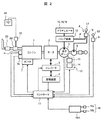
図1は本発明に係るハイブリッド式建設機械の一実施形態として挙げたハイブリッド式油圧ショベルの構成を示す図である。図2は本実施形態に係るハイブリッド式油圧ショベルの要部の構成を説明する図である。 FIG. 1 is a diagram showing a configuration of a hybrid hydraulic excavator cited as an embodiment of a hybrid construction machine according to the present invention. FIG. 2 is a diagram illustrating the configuration of the main part of the hybrid hydraulic excavator according to this embodiment.
本発明に係るハイブリッド式建設機械の一実施形態は、例えば図1に示すようにハイブリッド式油圧ショベル(以下、便宜的に油圧ショベルと呼ぶ)に適用される。この油圧ショベルは、走行体100と、この走行体100上に旋回フレーム111を介して旋回可能に設けられた旋回体110と、この旋回体110の前方に取り付けられ、上下方向に回動して掘削等の作業を行うフロント作業機70とを備えている。
One embodiment of a hybrid construction machine according to the present invention is applied to, for example, a hybrid hydraulic excavator (hereinafter referred to as a hydraulic excavator for convenience) as shown in FIG. This hydraulic excavator is attached to a traveling
フロント作業機70は、基端が旋回フレーム111に回動可能に取り付けられて上下方向に回動するブーム71と、このブーム71の先端に回動可能に取り付けられたアーム73と、このアーム73の先端に回動可能に取り付けられたバケット75とを有している。また、フロント作業機70は、旋回体110とブーム71とを接続し、伸縮することによってブーム71を回動させるブームシリンダ72と、ブーム71とアーム73とを接続し、伸縮することによってアーム73を回動させるアームシリンダ74と、アーム73とバケット75とを接続し、伸縮することによってバケット75を回動させるバケットシリンダ76とを有している。
The
旋回体110は、図1及び図2に示すように旋回フレーム111上の前部に設けられた運転室(キャビン)3と、旋回フレーム111上の後部の原動機室112内に設けられた原動機としてのエンジン1と、このエンジン1の燃料噴射量を調整するガバナ7と、エンジン1の実回転数を検出する回転数センサ1aと、エンジン1のトルクを検出するエンジントルクセンサ1bと、エンジン1の動力の補助及び発電を行う電動機としてのアシスト発電モータ2とを備えている。このアシスト発電モータ2は、エンジン1の駆動軸上に配置され、エンジン1との間でトルクの伝達を行う。
As shown in FIG. 1 and FIG. 2, the revolving
また、旋回体110は、アシスト発電モータ2の回転数を制御するインバータ装置9と、このインバータ装置9を介してアシスト発電モータ2との間で電力の授受を行う蓄電装置8と、上述したブームシリンダ72、アームシリンダ74及びバケットシリンダ76等の油圧アクチュエータへ供給する圧油の流量及び方向を制御するバルブ装置12とを備えている。
Further, the
旋回体110の原動機室112内には、油圧アクチュエータ72,74,76を駆動するための油圧システム90が配置されている。この油圧システム90は、油圧を発生する油圧源となる油圧ポンプ5と、パイロット圧油を発生するパイロット油圧ポンプ6と、バルブ装置12の操作部にパイロット管路Pを介して接続され、各油圧アクチュエータ72,74,76の所望の動作を可能とする操作装置4とを含んでいる。この操作装置4は、運転室3内に設けられており、操作者が把持して操作する操作レバー17を有している。
A
さらに、旋回体110は、油圧ポンプ5の容量を調整するポンプ容量調節装置10と、ガバナ7を調整してエンジン1の回転数を制御すると共に、インバータ装置9を制御してアシスト発電モータ2のトルクを制御する制御装置としてのコントローラ11とを備えている。なお、油圧ポンプ5、油圧アクチュエータ72,74,76,及びバルブ装置12によって油圧回路が構成されており、上述の回転数センサ1aによって検出されたエンジン1の実回転数、エンジントルクセンサ1bによって検出されたエンジン1のトルク及び操作レバー17の操作量等はコントローラ11に入力される。
Further, the
そして、油圧ポンプ5はアシスト発電モータ2を介してエンジン1に接続されており、油圧ポンプ5及びパイロット油圧ポンプ6はエンジン1及びアシスト発電モータ2の駆動力で動作することにより、油圧ポンプ5から吐出された圧油はバルブ装置12に供給され、パイロット油圧ポンプ6から吐出されたパイロット圧油は操作装置4に供給される。
The
このとき、運転室3内の操作者が操作レバー17を操作すると、操作装置4は、操作レバー17の操作量に応じたパイロット圧油をパイロット管路Pを介してバルブ装置12の操作部へ供給することにより、バルブ装置12内のスプールの位置がパイロット圧油によって切換えられ、油圧ポンプ5からバルブ装置12を流通した圧油が油圧アクチュエータ72,74,76へ供給される。これにより、油圧アクチュエータ72,74,76が油圧ポンプ5からバルブ装置12を介して供給された圧油によって駆動する。
At this time, when an operator in the
油圧ポンプ5は,可変容量機構として例えば斜板(図示せず)を有し、この斜板の傾斜角を調整することによって圧油の吐出流量を制御している。以下、油圧ポンプ5を斜板ポンプとして説明するが、圧油の吐出流量を制御する機能を有するものであれば、油圧ポンプ5は斜軸ポンプ等であっても良い。なお、油圧ポンプ5には図示されないが、油圧ポンプ5の吐出圧を検出する吐出圧センサ、油圧ポンプ5の吐出流量を検出する吐出流量センサ及び斜板の傾斜角を計測する傾斜角センサが設けられている。コントローラ11は、これらの各センサから得られた油圧ポンプ5の吐出圧、吐出流量及び斜板の傾斜角を入力して油圧ポンプ5の負荷を演算する。
The
ポンプ容量調節装置10は、コントローラ11から出力される操作信号に基づいて油圧ポンプ5の容量(押しのけ容積)を調節するものである。具体的には、ポンプ容量調節装置10は、斜板を傾転可能に支持するレギュレータ13と、コントローラ11の指令値に応じてレギュレータ13に制御圧を加える電磁比例弁14とを有する。レギュレータ13は、電磁比例弁14から制御圧を受けると、この制御圧によって斜板の傾斜角を変更することにより、油圧ポンプ5の容量(押しのけ容積)が調節され、油圧ポンプ5の吸収トルク(入力トルク)を制御することができる。
The pump
また、エンジン1の排気通路には、エンジン1から排出された排気ガスを浄化する排気ガス浄化システムが設けられている。この排気ガス浄化システムは、還元剤としての尿素から生成されたアンモニアによる排気ガス中の窒素酸化物の還元反応を促進する選択的接触還元触媒(SCR触媒)80と、尿素をエンジン1の排気通路内に添加する還元剤添加装置81と、この還元剤添加装置81へ供給する尿素を蓄える尿素タンク82と、エンジン1の排気音を消音するマフラ(消音機)83とを備えている。従って、エンジン1の排気ガスは、選択的接触還元触媒80で排気ガス中の窒素酸化物を無害な水と窒素に浄化してからマフラ83を介して大気へ放出される。
Further, an exhaust gas purification system for purifying exhaust gas discharged from the
上述したエンジン1、アシスト発電モータ2、インバータ装置9及び蓄電装置8は使用され続けることによって発熱するので、これらの機器の温度上昇を抑えるために、冷却装置を旋回体110内に備えている。
The
図3は運転室3内の操作レバー17a〜17d及び表示装置15の構成を詳細に示す図である。
FIG. 3 is a diagram showing in detail the configuration of the operation levers 17 a to 17 d and the
図3に示すように、操作レバー17a〜17dは、例えば、運転席18に着座した操作者が把持して車体の動作を手動で操作するものである。これらの各操作レバー17a〜17dの操作信号はコントローラ11へ送信される。
As shown in FIG. 3, the operation levers 17a to 17d are, for example, gripped by an operator seated in the driver's
操作レバー17aは、運転席18の前方左側に配置され、前方向(矢印A方向)に操作されることにより、走行体100の左側の履帯100aを前方向へ走行させる(左履帯前進)。操作レバー17aは後方向(矢印B方向)に操作されることにより、走行体100の左側の履帯100aを後方向へ走行させる(左履帯後退)。
The
操作レバー17bは、運転席18の前方右側に配置され、前方向(矢印C方向)に操作されることにより、走行体100の右側の履帯100aを前方向へ走行させる(右履帯前進)。操作レバー17bは、後方向(矢印D方向)に操作されることにより、走行体100の右側の履帯100aを後方向へ走行させる(右履帯後退)。
The
操作レバー17cは、運転席18の左側方に配置され、前方向(矢印E方向)に操作されることにより、旋回装置110aを左に旋回させ(左旋回)、後方向(矢印F方向)に操作されることにより、旋回装置110aを右に旋回させる(右旋回)。また、操作レバー17cは、左方向(矢印G方向)に操作されることにより、アーム73を上方向に回動させ(アーム伸ばし)、右方向(矢印H方向)に操作されることにより、アーム73を下方向に回動させる(アーム曲げ)。
The
操作レバー17dは、運転席18の右側方に配置され、前方向(矢印I方向)に操作されることにより、ブーム71を下方向に回動させ(ブーム下げ)、後方向(矢印J方向)に操作されることにより、ブーム71を上方向に回動させる(ブーム上げ)。また、操作レバー17dは、左方向(矢印K方向)に操作されることにより、バケット75を下方向に回動させ(バケット掘削)、右方向(矢印L方向)に操作されることにより、バケット75を上方向に回動させる(バケット開放)。
The
なお、運転室3には、操作レバー17a〜17dの操作状態、すなわち操作レバー17a〜17dの位置を検出する操作レバー状態検出部19(図2参照)が設けられている。
The
表示装置15は、コントローラ11から受信した情報を映し出すモニタ15aと、このモニタ15aの電源をON状態又はOFF状態に切替える電源スイッチ及びこの電源スイッチがON状態のときにモニタ15aに映し出される映像を切替える切替スイッチ等の操作スイッチ15bとから構成されている。
The
運転席18の左側に配置されたゲートロックレバー50は、油圧ショベルの動作の可否を切り替えるレバーである。ゲートロックレバー50を前方に倒すことによりONとなり、操作レバー17を操作しても履帯100a、旋回装置110a、ブーム71、アーム73及びバケット75が動作しない状態となる。このゲートロックレバー50は油圧ショベルの安全装置である。油圧ショベルを動作させるためには、ゲートロックレバー50を後方に倒してOFFとし、操作レバー17を操作する。なお、運転室3には、ゲートロックレバー50の操作状態、すなわちゲートロックレバー50の位置を検出するゲートロックレバー状態検出部51(図2参照)が設けられている。
The
また、運転室3には、油圧ショベルの動作出力を設定する出力設定部16が設けられている。この出力設定部16は、例えばエンジン回転数を調整して油圧ショベルの動作出力を設定するエンジン回転数調整ダイヤル16aや、エコノミーモードやパワーモードを設定する出力モード設定スイッチ16bから成っている。エンジン回転数調整ダイヤル16aや出力モード設定スイッチ16bは、運転室3内の操作者が作業内容に応じて、車体の動作出力の設定を「小出力」(軽負荷作業を行うのに適した設定)又は「大出力」(高負荷作業を行うのに適した設定)に選択するようになっている。この出力設定部16の状態は、出力設定検出部16A(図2参照)で検出され、コントローラ11に入力される。
The
ここで、蓄電装置8には電流制限がなく使用できる上限温度があるので、蓄電装置8の温度が過度に高くならないように冷却する必要がある。また、蓄電装置8は低温時に許容出力が低下する。図4は蓄電装置8の充電率(SOC)と許容出力との関係を蓄電装置8の温度(低温度,中温度,高温度)毎に示す図である。図4に示すように蓄電装置8は、低温時に許容出力が低下する。従って、許容出力を低下させることなく蓄電装置8を使用するためには、蓄電装置8を所定の温度以上に暖める必要がある。すなわち、蓄電装置8を暖機することにより、蓄電装置8を適切な温度範囲に保つ必要がある。特に、外気の温度が低い冬季における油圧ショベルの始動時等では、蓄電装置8の許容出力を高めるために作業が開始される前に蓄電装置8を予め暖機しておくと良い場合がある。
Here, since the
図5は、蓄電装置8を冷却又は暖機し、適切な温度範囲に保つ温調装置20の構成を示す図である。
FIG. 5 is a diagram showing a configuration of the
図5に示すように、温調装置20は、冷却水等の冷却媒体を蓄電装置8の近傍(熱の授受が可能な位置)に循環させて蓄電装置8を冷却する冷却回路21と、エンジン冷却水等の加温媒体を蓄電装置8の近傍(熱の授受が可能な位置)に循環させて蓄電装置8を暖機する暖機回路25を含む。
As shown in FIG. 5, the
冷却回路21は、冷却媒体が内部を流通する液配管22と、この液配管22内で冷却媒体を循環させるポンプ23と、蓄電装置8と冷却媒体との間で熱交換を行う熱交換部材としてのウォータジャケット24と、冷却媒体と外気との間で熱交換を行うバッテリラジエータ26とから構成されており、これらの各機器は液配管22によって順に環状に接続されている。なお,バッテリラジエータ26には、外気を旋回体110内へ取り込んで冷却媒体等を冷却する送風用のファン27が取り付けられている。
The
暖機回路25は、エンジン1を冷却することによって暖められた加温媒体(エンジン冷却水)が内部を流通する液配管37と、この液配管37内で加温媒体を循環させるポンプ38と、蓄電装置8と加温媒体との間で熱交換を行う熱交換部材としてのウォータジャケット24と、ウォータジャケット24に加温媒体を流すか否かを切り替える制御弁35とから構成されており、これらの各機器は液配管37によって順に環状に接続されている。暖機回路25と並列に暖房回路41とエンジン冷却回路42を備えており、暖房回路41にあるヒータコア40に加温媒体を循環することにより、運転室3内を暖めることができる。エンジン冷却回路42には、加温媒体(エンジン冷却水)と外気との間で熱交換を行うエンジンラジエータ28と、加温媒体(エンジン冷却水)が所定温度以上になった場合に加温媒体をエンジン冷却回路42に循環するサーモスタット39とが設けられている。なお、エンジンラジエータ28には、外気を旋回体110内へ取り込んで加温媒体(エンジン冷却水)を冷却する送風用のファン29が取り付けられている。
The warm-
蓄電装置8は、塵埃や水等の異物が混入して破損することを防ぐために、保護カバー等で覆われるのが好ましい。
The
冷却回路21にあるポンプ23は電動ポンプであり、コントローラ11によりON/OFF制御される。一方、暖機回路25にあるポンプ38は、エンジン1に直結したポンプでありエンジン1の駆動とともに常に動作している。
The
制御弁35は、ON時に開となるノーマルクローズ弁としており、コントローラ11によりON/OFF制御される。制御弁35は、OFF時には閉となり加温媒体がウォータジャケット24に循環せず、蓄電装置8の暖機は行われない。制御弁35は、ON時に開となり加温媒体がウォータジャケット24に循環し、蓄電装置8を暖機する。
The
蓄電装置8は、例えばウォータジャケット24に沿って直列に配置された複数の電池セル30から構成されている。これらの電池セル30は、熱伝導シート36を介してウォータジャケット24に熱結合状態で固定されている。各電池セル30は、角形形状のリチウムイオン二次電池から成っている。ただし、各電池セル30は、リチウムイオン二次電池の代わりに、ニッケル水素電池やニッケルカドミウム電池等の他の電池やキャパシタであっても良い。
The
また、蓄電装置8に流れる電流を計測する電流計測部としての電流センサ31、各電池セル30の電圧を計測する電圧計測部としての電圧センサ32、各電池セル30の上部温度を計測する上部温度計測部としての上部温度センサ33及び各電池セル30の下部温度を計測する下部温度計測部としての下部温度センサ34がそれぞれ取り付けられている。複数のセンサから得られる電圧及び温度はコントローラ11で演算され、各電池セル30の電圧及び温度の計測値から蓄電装置8における電圧及び温度の平均値、最大値及び最小値が算出される。そして、コントローラ11は、電流センサ31によって計測された電流、電圧センサ32によって計測された電圧、上部温度センサ33によって計測された温度及び下部温度センサ34によって計測された温度等に基づいて蓄電装置8の蓄電量を演算することにより、蓄電装置8の蓄電量を管理している。また、コントローラ11は、例えば演算した蓄電装置8の蓄電量から充電率(SOC)を算出するようにしている。
In addition, a current sensor 31 as a current measurement unit that measures the current flowing through the
なお、電圧センサ32、上部温度センサ33及び下部温度センサ34は、図5に示すように電池セル30の全てに設置しなくてもよく、代表的な点を測定できればよい。また、下部温度センサ34は、電池セル30の下部の温度を測定するために備えるが、設置上の制約から電池セル30近傍のウォータジャケット24に設置してもよい。さらに、下部温度センサ34は、後述するように電池セル30の上下の温度差を求めるのに使用するため、上部温度センサ33を設置した電池セル30に下部温度センサ34を設置することが望ましい。
In addition, the
図5では、ファン27及びファン29を別のものとして記載しているが、1つのファンによりバッテリラジエータ26及びエンジンラジエータ28に送風するものであっても良い。また、ファン27,29は、エンジン1により直接駆動するようにしている。
In FIG. 5, the
ウォータジャケット24は、薄板状の金属部材により形成されており、冷却媒体と加温媒体を循環させる流路を有する。ウォータジャケット24には、図示されないが、冷却媒体が内部へ流入する冷却媒体入口と、内部に形成され、この冷却媒体入口から流入した冷却媒体を循環させる溝と、この溝を循環した冷却媒体が外部へ流出する冷却媒体出口と、加温媒体が内部へ流入する加温媒体入口と、内部に形成され、この加温媒体入口から流入した加温媒体を循環させる溝と、この溝を循環した加温媒体が外部へ流出する加温媒体出口とを備えている。ウォータジャケット24の内部を循環する冷却媒体と加温媒体は、熱伝導シート36を介して各電池セル30と熱の授受を行っている。
The
また、ウォータジャケット24は、上述したように金属部材であることから隣接する各電池セル30との間で電位差が存在する。そのため、電池セル30をウォータジャケット24に直接接触させると、大きなショート電流が流れる。電池セル30とウォータジャケット24との間に介在する熱伝導シート36は、このようなショート電流を回避する機能を有している。すなわち、熱伝導シート36は、電池セル30とウォータジャケット24とを絶縁し、かつ、電池セル30とウォータジャケット24との間で熱交換を効率良く行うものである。なお、熱伝導シート36は弾性体から成り、この弾性体として、例えばシリコン樹脂シート、熱伝導の優れたフィラーが充填されているプラスチックシート或いはマイカ等を用いるが、同様の機能を有するものであれば、他のものを用いても良い。
Moreover, since the
上記では、加温媒体としてエンジン1を冷却することによって暖められたエンジン冷却水を用いたが、同様の効果が得られれば他のものであってもよく、ヒータやアシスト発電モータ2或いはインバータ装置9等の車載機器で暖められたものであってもよい。
In the above, engine cooling water warmed by cooling the
図2に示すコントローラ11は、蓄電装置8を冷却又は暖機し、適切な温度範囲に保つ温調装置20の制御装置としての機能を有している。また、コントローラ11は、暖機のため蓄電装置8を強制的に充放電して蓄電装置8の内部抵抗(DCR)で発熱させる機能も有している。このように本実施形態に係る蓄電装置8の暖機運転は、加温媒体と蓄電装置8の充放電といった複数の方法により行うことにしている。
The
次に、本実施形態に係る温調装置20の運転動作について図6、図7及び図8を参照して説明する。図6は、本実施形態に係る温調装置の冷却運転の動作を説明するフローチャートである。図7は、本実施形態に係る温調装置の暖機運転の動作を説明するフローチャートである。図8は、本実施形態に係る温調装置の暖機運転の制御弁のON/OFF制御の動作を説明するフローチャートである。
Next, the operation | movement operation | movement of the
蓄電装置8の温度調整は、蓄電装置8の熱が伝達された冷却媒体をバッテリラジエータ26により冷却する場合(冷却運転)、およびエンジン排熱に暖められた加温媒体と蓄電装置8の充放電とにより暖機する場合(暖機運転)がある。温調装置20の動作は蓄電装置8の温度に応じて変化する。図6、図7及び図8の動作は、所定の時間毎に温度、電圧及び電流を計測して、繰り返して行われる。
The temperature adjustment of the
まず、本実施形態に係るコントローラ11による蓄電装置8の冷却運転の動作について、図6に示すフローチャートを用いて説明する。冷却運転は、複数ある上部温度センサ33によって計測された蓄電装置8の最高温度が所定の温度T1より高い場合に行われる。
First, the cooling operation of the
S201において、制御弁35をOFFとし、加温媒体をウォータジャケット24に循環させないようにする。これにより加温媒体の熱が蓄電装置8に伝わらないようになる。次にS202において、ポンプ23をONとし、冷却媒体をウォータジャケット24に循環させる。このとき、蓄電装置8で発生した熱は、ウォータジャケット24内を流通する冷却媒体に伝わる。ウォータジャケット24内で暖められた冷却媒体は、バッテリラジエータ26に供給されて冷却される。なお、蓄電装置8の温度を制御するためには、ポンプ23から吐出される冷却媒体の流量又はファン27によって送風される外気の風量を調整すれば良い。
In S201, the
具体的には、上部温度センサ33によって計測された蓄電装置8の温度が高い場合には、ポンプ23から吐出される冷却媒体の流量を増加させたり、あるいはファン27によって送風される外気の風量を増加させたりすれば良い。一方、上部温度センサ33によって計測された蓄電装置8の温度が低い場合には、ポンプ23から吐出される冷却媒体の流量を減少させたり、あるいはファン27によって送風される外気の風量を減少させたりすれば良い。
Specifically, when the temperature of the
次に、本実施形態に係るコントローラ11による蓄電装置8の暖機運転の動作について、図7に示すフローチャートを用いて説明する。暖機運転は、複数ある上部温度センサ33によって計測された蓄電装置8の最低温度が所定の温度T2より低い場合に行われる。
Next, the operation of the warm-up operation of the
S301において、ポンプ23をOFFにし、冷却媒体をウォータジャケット24に循環させないようにする。これにより、蓄電装置8の熱がウォータジャケット24から冷却媒体へ逃げるのを防ぐことができる。次にS302において、制御弁35のON/OFF制御を行う。なお、制御弁35の制御の詳細は後述する。
In S301, the
そして、S303において、油圧ショベルが起動直後の運転か否かを判定する。起動直後の場合にはS304において暖機運転用の蓄電装置8の充放電を行う。起動直後は蓄電装置8の最低温度と温度T2との温度差が大きく、加温媒体による暖機運転と蓄電装置8の充放電による暖機運転とを併用して速やかに蓄電装置8を暖機するためである。この場合、加温媒体による暖機運転では、必要に応じて、アシスト発電モータ2及び油圧ポンプ5等の機器を駆動して、エンジン1の負荷を高めるように制御し、加温媒体の温度を上げて暖機運転の効果を高めるようにするとよい。S303において、油圧ショベルが起動直後の運転ではなく、上部温度センサ33によって計測された蓄電装置8の最低温度が、一度、所定温度T2以上に到達した後に低下した場合には、暖機のための蓄電装置8の充放電は行わない。蓄電装置8の充放電を行わないのは、蓄電装置8の最低温度と温度T2との差が小さく、加温媒体による暖機により速やかに蓄電装置8の温度上昇が可能であるからである。また、蓄電装置8の充放電回数を減らすことにより、蓄電装置8の劣化を抑制でき、かつ、油圧ショベルの消費エネルギを低減することができるからである。なお、油圧ショベルの動作に必要な蓄電装置8の充放電は行う。
In step S303, it is determined whether or not the excavator is operating immediately after startup. In the case of immediately after startup, charging / discharging of the
以上のようにして、温調装置20を運転し、蓄電装置8を冷却又は暖機して適切な温度範囲に保つが、上部温度センサ33の最低温度がT2以上、かつ、最高温度がT1以下の場合には、冷却運転も暖機運転も行わないことにしている。
As described above, the
次に、S302に示す制御弁35のON/OFF制御について、図8に示すフローチャートを用いて説明する。この制御は、加温媒体をウォータジャケット24に循環するか否かを切り替えるものである。
Next, the ON / OFF control of the
S401において、下部温度センサ34の温度が予め設定された所定温度T3より高いか否かを判定する。S401において電池セル30の下部温度がT3より高いと判定された場合には、S403において制御弁35をOFFとし、加温媒体による暖機運転を停止する。これは、電池セル30の下部が高温になるのを防止するためである。S401において電池セル30の下部温度が所定温度T3以下である場合には、S402において電池セル30の上部と下部の温度差が予め設定された所定温度T4以上か否かを判定する。S402において電池セル30の上部と下部の温度差が所定温度T4以上の場合には、S404において制御弁をOFFとし、加温媒体による暖機運転を停止する。これは、電池セル30の内部の温度ばらつきを抑えるためである。電池セル30内の温度ばらつきは、電池セル30の内部抵抗のばらつきを生じ、電流の流れやすい部分と流れにくい部分に分かれ、電池の劣化を早めるおそれがあるからである。S402において電池セル30の上部と下部の温度差が所定温度T4より小さい場合には、S405において制御弁35をONとし、加温媒体による暖機運転を行う。
In S401, it is determined whether or not the temperature of the
なお、S401の判定に用いる電池セル30の下部温度は、全ての下部温度センサ34の中での最高温度としても良いし、予め最も下部温度が高い点がわかっているのであれば、その点でもよい。また、S402の判定に用いる電池セル30の上部と下部の温度差は、全ての計測箇所の中での最大温度差としても良いし、予め最も温度差が大きい箇所がわかっているのであれば、その点でもよい。
Note that the lower temperature of the
以上のようにして、制御弁35のON/OFF制御を行い、電池セル30の下部が高温になるのを防止し、かつ、電池セル30内部の温度ばらつきを抑制するようにしている。
As described above, ON / OFF control of the
ここで、加温媒体による暖機運転により電池セル30内に温度ばらつきが生じやすいのは、図5に示すように低温の電池セル30の下面を加温媒体により暖めるからである。電池セル30の側面や上面も加温媒体により暖めることができればよいが、蓄電装置8の構造上の制約により困難である。そのため、電池セル30の下部の温度が上部の温度より高くなる。
Here, the reason why the temperature variation easily occurs in the
次に、S304に示す暖機運転のための蓄電装置8の充放電電流の算出について説明する。
Next, calculation of the charge / discharge current of the
暖機運転のための充放電電流は、例えば電圧センサ32によって計測された電圧、蓄電装置8の充放電の状態及び蓄電装置8の電圧の所定の上下限値Vmax,Vminに基づいて演算される。ここで、蓄電装置8に負荷を接続した状態における1個の電池セル30の端子間電圧である閉路電圧(CCV)をV1、蓄電装置8に負荷を接続していない状態における1個の端子間電圧である開路電圧(OCV)をV2、蓄電装置8の内部抵抗(DCR)をr、蓄電装置8に流れる電流をIとすると、次の数式(数1)が成り立つ。
V1=V2+r・I (数1)
なお、蓄電装置8の電圧の所定の上下限値は、電池セル30の電圧上限値Vmax及び電圧下限値Vminとして、電池セル仕様又は油圧ショベルのシステム仕様により予め定められている。
The charge / discharge current for the warm-up operation is calculated based on, for example, the voltage measured by the
V1 = V2 + r · I (Equation 1)
The predetermined upper and lower limit values of the voltage of the
蓄電装置8の各電池セル30の電圧は、電圧上限値Vmaxと電圧下限値Vminの範囲に設定される必要があるので、充電時の電流Iを正の値とすると、閉路電圧(CCV)V1が電圧上限値Vmaxより小さくなる電流Iに設定する必要がある。一方、放電時の電流Iを負の値とすると、閉路電圧(CCV)V1が電圧下限値Vminより大きくなる電流Iに設定する必要がある。
Since the voltage of each
上述の数1に示される開路電圧(OCV)V2は、電池セル30の温度と充電率(SOC)により変化し、内部抵抗(DCR)rも電池セル30の温度と充電率(SOC)により変化する。特に、内部抵抗(DCR)rは、低温時に大きくなるので、閉路電圧(CCV)V1を電圧上限値Vmaxより小さく、電圧下限値Vminより大きくする電流Iは小さくなる。すなわち、電流Iは、低温ほど小さく、高温ほど大きくなる。なお、蓄電装置8の充放電の状態(充電または放電)によって蓄電装置8に流す電流は異なり、充放電の状態は、蓄電装置8の充電率(SOC)に応じてコントローラ11で判定する。
The open circuit voltage (OCV) V2 expressed by the
暖機運転中の蓄電装置8の放電は、油圧回路を構成する油圧ポンプ5、油圧アクチュエータ72,74,76及びバルブ装置12の少なくとも一つを動作するようにしている。エンジン1及び油圧ポンプ5はアシスト発電モータ2に機械的に接続されているので、これらのエンジン1及び油圧ポンプ5がアシスト発電モータ2の電気的な負荷となる。また、暖機運転中の蓄電装置8の充電は、アシスト発電モータ2を発電させて行われる。
The discharge of the
なお、上記で算出された電流の絶対値は、油圧ショベルでの制限により小さくしてもよい。また、本実施形態では油圧ショベルの動作を優先して蓄電装置8の充放電を行うようにしている。
It should be noted that the absolute value of the current calculated above may be reduced due to the limitation of the hydraulic excavator. In this embodiment, the
以上のように油圧ショベルが起動直後の暖機運転では、加温媒体と蓄電装置8の充放電を併用する。加温媒体だけでなく、蓄電装置8の充放電を行うのは、暖機時間(暖機運転に要する時間)を短くするだけでなく、蓄電装置8を内部から暖め、蓄電装置8内の温度ばらつきを抑えるためである。すなわち、加温媒体による暖機運転と蓄電装置8の充放電による暖機運転とを併用することにより、加温媒体による暖機運転により蓄電装置8を外部から温め、蓄電装置8の充放電により蓄電装置8を内部から温めることができる。これにより、蓄電装置8を効率良く、かつ、均一に温めることができる。しかし、蓄電装置8の劣化や、油圧ショベルの消費エネルギ低減を考慮すると、蓄電装置8の充放電は可能な限り行わない方が望ましい。
As described above, in the warm-up operation immediately after the hydraulic excavator is started, the heating medium and charging / discharging of the
そこで、外気温度や油圧ショベルの状態により、暖機運転のための蓄電装置8の充放電を行わないことにしている。油圧ショベルの状態は、車体状態検出部(車体状態検出手段)で検出する。本実施例では、車体状態検出部は、エンジン回転数設定、出力モード設定、操作レバー状態、ゲートロックレバー状態を検出するように構成している。エンジン回転数設定と出力モード設定は、エンジン調整ダイヤル16aと出力モード設定スイッチ16bからなる出力設定部16の設定を出力設定検出部16Aで検出する。操作レバー状態とゲートロックレバー状態は、それぞれ操作レバー状態検出部19とゲートロックレバー状態検出部51で検出する。すなわち、本実施例では、車体状態検出部は、出力設定検出部16A、操作レバー状態検出部19及びゲートロックレバー状態検出部51で構成される。なお、外気温度は、外気温度計測手段(外気温度計測装置)で検出するが、例えば上部温度センサ33の初期温度は外気温度に等しいので、この初期温度を外気温度として用いることができる。外気温度を検出できれば他のものであっても構わない。例えば、外気温度計測手段として、エンジンの吸入空気温度センサやエアコンの温度センサを用いてもよい。
Therefore, charging / discharging of the
次に、外気温度や油圧ショベルの状態と電池セル30の内部温度ばらつき及び暖機時間の関係と、暖機方法の切替えについて説明する。
Next, the relationship between the outside air temperature, the state of the hydraulic excavator, the internal temperature variation of the
図9は、外気温度による電池セルの内部温度ばらつきと暖機時間の関係と、外気温度に応じた暖機方法の切替えを説明する図である。 FIG. 9 is a diagram for explaining the relationship between the internal temperature variation of the battery cell due to the outside air temperature and the warm-up time, and switching of the warm-up method according to the outside air temperature.
図9に示すように、外気温度が低い場合には、電池セル30の初期温度が低いため、加温冷媒で暖機する際に電池セル30の内部温度ばらつきが大きくなりやすい。また、電池セル30の初期温度が低く、電池セル30やウォータジャケット24等からの放熱量が大きいため、暖機時間(暖機に要する時間)が長くなる。したがって、外気温度が低い場合には、加温媒体と蓄電装置の充放電とによる暖機運転が必要である。また、外気温度が高い場合には、電池セル30の内部温度ばらつきが小さく、暖機時間が短いため、加温媒体のみの暖機運転で十分である。
As shown in FIG. 9, when the outside air temperature is low, the initial temperature of the
図10は、エンジン回転数設定による電池セル30の内部温度ばらつきと暖機時間の関係と、エンジン回転数設定に応じた暖機方法の切替えを説明する図である。
FIG. 10 is a diagram for explaining the relationship between the internal temperature variation of the
図10に示すように、エンジン回転数設定が小さい場合には、エンジン出力が小さくエンジン1の排熱が小さくなるため加温媒体の温度が低くなるので電池セル30の内部温度ばらつきが小さくなる。また、エンジン回転数設定が小さいということは、操作者が油圧ショベルに大出力を要求していないことを意味するため、暖機時間(暖機に要する時間)は長くてもよい。これは、図4からもわかるように、出力を小さくしても良い場合には、蓄電装置8の温度を低くてもよいからである。したがって、エンジン回転数設定が小さい場合には、加温媒体のみの暖機運転で十分である。また、エンジン回転数設定が大きい場合には、電池セル30の内部温度ばらつきが大きくなり、操作者は暖機時間を短かくしたいため、加温媒体と蓄電装置の充放電による暖機運転が必要である。
As shown in FIG. 10, when the engine speed setting is small, the engine output is small and the exhaust heat of the
図11は、出力モード設定による電池セル30の内部温度ばらつきと暖機時間の関係と、出力モード設定に応じた暖機方法の切替えを説明する図である。
FIG. 11 is a diagram illustrating the relationship between the internal temperature variation of the
図11に示すように、出力モード設定がエコモードの場合には、エンジン出力が小さくエンジン1の排熱が小さくなるため加温媒体の温度が低くなるので、電池セル30の内部温度ばらつきが小さくなる。また、操作者が油圧ショベルに大出力を要求していないことを意味するため、上記のように暖機時間(暖機に要する時間)は長くてもよい。したがって、出力モード設定がエコモードの場合には、加温媒体のみの暖機運転で十分である。また、出力モード設定がパワーモードの場合には、電池セル30の内部温度ばらつきが大きくなり、操作者は暖機時間を短かくしたいため、加温媒体と蓄電装置の充放電による暖機運転が必要である。
As shown in FIG. 11, when the output mode setting is the eco mode, the engine output is small and the exhaust heat of the
図12は、レバー操作の有無による電池セル30の内部温度ばらつきと暖機時間の関係と、レバー操作の有無に応じた暖機方法の切替えを説明する図である。
FIG. 12 is a diagram for explaining the relationship between the internal temperature variation of the
図12に示すように、操作者が操作レバー17を動かさず、フロント作業機70の暖機運転をしていない場合には、エンジン出力が小さくエンジン1の排熱が小さくなるため加温媒体の温度が低くなるので、電池セル30の内部温度ばらつきが小さくなる。また、操作者が油圧ショベルを早く操作しなくてもよいことを意味するため、暖機時間(暖機に要する時間)は長くてもよい。したがって、レバー操作が無い場合には、加温媒体のみの暖機運転で十分である。また、レバー操作が有る場合には、電池セル30の内部温度ばらつきが大きくなり、操作者は暖機時間を短かくしたいため、加温媒体と蓄電装置の充放電による暖機運転が必要である。
As shown in FIG. 12, when the operator does not move the
図13は,ゲートロックレバーの位置による電池セル30の内部温度ばらつきと暖機時間の関係と、ゲートロックレバーの位置に応じた暖機方法の切替えを説明する図である。
FIG. 13 is a diagram for explaining the relationship between the internal temperature variation of the
図13に示すように、ゲートロックレバーがONであり、フロント作業機70の暖機運転をしていない場合には、エンジン出力が小さくエンジン1の排熱が小さくなるため加温媒体の温度が低くなるので、電池セル30の内部温度ばらつきが小さくなる。また、操作者が油圧ショベルを早く操作しなくてもよいことを意味するため、暖機時間(暖機に要する時間)は長くてもよい。したがって、ゲートロックレバーがONの場合には、加温媒体のみの暖機運転で十分である。また、ゲートロックレバーがOFFの場合には、電池セル30の内部温度ばらつきが大きくなり、操作者は暖機時間を短かくしたいため、加温媒体と蓄電装置の充放電による暖機運転が必要である。
As shown in FIG. 13, when the gate lock lever is ON and the
以上のように、外気温度や油圧ショベルの状態により暖機方法を切り替えることにしている。これにより、暖機運転のための蓄電装置8の充放電を減らすことができる。したがって、電池セル30内の温度ばらつきを抑え、かつ、暖機時間の要求を損なうことなく、蓄電装置8の長寿命化と油圧ショベルの消費エネルギ低減を図ることができる。なお、上述の暖機運転においては、主として加温媒体による暖機運転(温調装置20による暖機運転)を行い、必要に応じて蓄電装置8の充放電による暖機運転を加温媒体による暖機運転に組み合わせて行う。このような暖機運転は、加温媒体による暖機運転を行いつつ、外気温度や油圧ショベルの状態に応じて蓄電装置8の充放電による暖機運転をON/OFFして実行される。
As described above, the warm-up method is switched according to the outside air temperature and the state of the hydraulic excavator. Thereby, charging / discharging of the
また、図9〜図13では外気温度や油圧ショベルの状態の一つずつに対して暖機方法を切り替える例を示したが、図14に示すように外気温度とエンジン回転数設定により暖機方法(暖機運転のための蓄電装置8の充放電の有無)を切り替えてもよい。図14は、外気温度とエンジン回転数設定とに応じた暖機方法を説明する図である。図14では、例えばエンジン回転数を大、中、小と設定できるものとし、エンジン回転数と外気温度とから、暖機運転のための蓄電装置8の充放電の有無を切り替えている。エンジン回転数設定が大きく,外気温度が低いほど蓄電装置8の充放電を行うことにしている。すなわち、エンジン回転数が大きい場合は、エンジン回転数が小さい場合と比べて、高い外気温度で蓄電装置8の充放電が有りから無しに切り替わるようにしている。これは、電池セル30の内部温度ばらつきが大きくなりやすく、暖機時間を短縮する必要があるからである。
9 to 13 show an example in which the warm-up method is switched for each one of the outside air temperature and the state of the hydraulic excavator. However, as shown in FIG. 14, the warm-up method is set by setting the outside air temperature and the engine speed. (Presence / absence of charge / discharge of
図15は、外気温度と出力モード設定とに応じた暖機方法、または、外気温度とレバー操作とに応じた暖機方法、または、外気温度とゲートロックレバー位置とに応じた暖機方法を説明する図である。図15に示すように、外気温度と出力モード設定、または、外気温度とレバー操作、または、外気温度とゲートロックレバー位置により暖機方法(暖機運転のための蓄電装置8の充放電の有無)を切り替えてもよい。図15では、出力モード設定が「パワー」の場合に「エコ」と比較して、レバー操作が「有り」の場合に「無し」の場合と比較して、またゲートロックレバー位置がONの場合にOFFの場合と比較して、高い外気温度で蓄電装置8の充放電が有りから無しに切り替わるようにしている。
FIG. 15 shows a warm-up method according to the outside air temperature and the output mode setting, a warm-up method according to the outside air temperature and the lever operation, or a warm-up method according to the outside air temperature and the gate lock lever position. It is a figure explaining. As shown in FIG. 15, the warm-up method (presence / absence of charging / discharging of
運転室3内に備えた表示装置15のモニタ15aには、温調装置20の運転モード(冷却、暖機)、暖機運転のための蓄電装置8の充放電の有無を表示する。また、暖機時間を早めるための出力設定部16の設定や操作レバー17やゲートロックレバー50の操作をモニタ15aに表示することにしている。操作者は、モニタ15aを見て設定や操作を変更することにより、暖機時間を短くすることが可能となる。
The
次に、本実施形態のように外気温度に基づいて暖機方法を切り替える場合と、本実施形態との比較例として電池温度に基づいて暖機方法を切り替える場合との差異について説明する。図16は、外気温度に基づいて暖機方法を切り替える場合と電池温度に基づいて暖機方法を切り替える場合とについて、暖機運転の状態を示す図である。図16において、上部には、縦軸はバッテリ温度(蓄電装置温度)T、横軸は時間であり、暖機運転に伴うバッテリ温度Tの時間変化を示している。また、図16の下部に、バッテリ温度Tの時間変化に対する暖機運転の切替えについて、本実施形態の場合と比較例の場合とについて示している。なお、本実施形態は外気温度に応じて蓄電装置8の充放電による暖機運転W2の開始および停止を制御するのに対して、比較例では蓄電装置8或いは電池セル30の温度(以下、バッテリ温度という)に基づいて充放電による暖機運転W2の開始および停止を制御している。
Next, the difference between the case where the warm-up method is switched based on the outside temperature as in the present embodiment and the case where the warm-up method is switched based on the battery temperature will be described as a comparative example with the present embodiment. FIG. 16 is a diagram illustrating a state of the warm-up operation when the warm-up method is switched based on the outside air temperature and when the warm-up method is switched based on the battery temperature. In FIG. 16, the vertical axis indicates the battery temperature (power storage device temperature) T and the horizontal axis indicates time, and shows the time change of the battery temperature T accompanying the warm-up operation. Further, in the lower part of FIG. 16, the switching of the warm-up operation with respect to the time change of the battery temperature T is shown for the case of this embodiment and the case of the comparative example. In the present embodiment, the start and stop of the warm-up operation W2 due to charging / discharging of the
バッテリ温度Tについて、4つの温度が設定されている。温度Taは初期温度であり、この点P1における蓄電装置8の温度と外気温度とは同じ(Ta)である。温度Tbは暖機運転を切り替える温度であり、温度Tbでは、加温媒体による暖機運転W1と蓄電装置8の充放電による暖機運転W2とを併用する暖機運転から、加温媒体による単独の暖機運転W1に切り替える。温度Tcは暖機運転W1,W2を終了する温度である。
For the battery temperature T, four temperatures are set. The temperature Ta is an initial temperature, and the temperature of the
初期温度Taの点P1では、本実施形態と比較例との間に差異はなく、加温媒体による暖機運転W1と蓄電装置8の充放電による暖機運転W2とを併用した暖機運転が開始される。暖機運転W1,W2によりバッテリ温度が上昇して温度Tbに達すると、比較例では点P2で蓄電装置8の充放電による暖機運転W2を停止し、以後、加温媒体による単独の暖機運転W1に移行する。一方、本実施形態では、バッテリ温度が上昇しても、外気温度が上昇しなければ暖機運転の切替えは行われないので、加温媒体による暖機運転W1と蓄電装置8の充放電による暖機運転W2とを併用する暖機運転が継続される。そして、バッテリ温度が温度Tcに達すると、本実施形態と比較例とはともに暖機運転を停止する。
At the point P1 of the initial temperature Ta, there is no difference between the present embodiment and the comparative example, and the warm-up operation using both the warm-up operation W1 by the heating medium and the warm-up operation W2 by charging and discharging of the
外気温度が低い場合は放熱量が多いため、暖機運転中に暖機方法を変化させないことが好ましい。比較例のようにバッテリ温度に基づいて暖機方法を切り替えると、外気温度が低い状態において暖機方法が切り替わることになる。これに対し、本実施形態では、外気温度が低い状態では暖機方法が切り替わらないので、安定した暖機運転を実施できる。 When the outside air temperature is low, the amount of heat released is large, so it is preferable not to change the warm-up method during the warm-up operation. When the warm-up method is switched based on the battery temperature as in the comparative example, the warm-up method is switched in a state where the outside air temperature is low. On the other hand, in this embodiment, since the warm-up method is not switched when the outside air temperature is low, a stable warm-up operation can be performed.
なお、本発明は上記した実施形態に限定されるものではなく、様々な変形例が含まれる。例えば、上記した実施形態例は本発明を分かりやすく説明するために詳細に説明したものであり、必ずしも説明した全ての構成を備えるものに限定されるものではない。また、実施形態の構成の一部について、他の構成の追加・削除・置換をすることが可能である。 In addition, this invention is not limited to above-described embodiment, Various modifications are included. For example, the above-described exemplary embodiments have been described in detail for easy understanding of the present invention, and are not necessarily limited to those having all the configurations described. Further, it is possible to add, delete, and replace other configurations for a part of the configuration of the embodiment.
また、本実施形態に係るハイブリッド式建設機械はハイブリッド式油圧ショベルから成る場合について説明したが、この場合に限らず、ハイブリッド式ホイールローダ等の建設機械であっても良い。 The hybrid construction machine according to the present embodiment has been described with respect to a hybrid hydraulic excavator. However, the present invention is not limited to this and may be a construction machine such as a hybrid wheel loader.
1:エンジン(原動機)、2:アシスト発電モータ(電動機)、4:操作装置、8:蓄電装置、11:コントローラ、15:表示装置、15a:モニタ、15b:操作スイッチ、16:出力設定部、16a:エンジン回転数調整ダイヤル(出力設定部)、16b:出力モード設定スイッチ、17:操作レバー、19:操作レバー状態検出部、20:温調装置、22:液配管、23:ポンプ、24:ウォータジャケット、25:暖機回路、30:電池セル、33:上部温度センサ、34:下部温度センサ、35:制御弁、36:熱伝導シート、40:ヒータコア、41:暖房回路、42:エンジン冷却回路、50:ゲートロックレバー、51:ゲートロックレバー状態検出部。 1: engine (motor), 2: assist generator motor (motor), 4: operating device, 8: power storage device, 11: controller, 15: display device, 15a: monitor, 15b: operation switch, 16: output setting unit, 16a: engine speed adjustment dial (output setting unit), 16b: output mode setting switch, 17: operation lever, 19: operation lever state detection unit, 20: temperature control device, 22: liquid piping, 23: pump, 24: Water jacket, 25: warm-up circuit, 30: battery cell, 33: upper temperature sensor, 34: lower temperature sensor, 35: control valve, 36: heat conduction sheet, 40: heater core, 41: heating circuit, 42: engine cooling Circuit: 50: Gate lock lever, 51: Gate lock lever state detector.
Claims (5)
前記制御装置は、
前記外気温度計測装置で計測する外気温度に応じて、
前記加温媒体の循環を制御することによる前記蓄電装置の暖機運転のみを行うか、或いは前記加温媒体の循環を制御することによる前記蓄電装置の暖機運転と前記蓄電装置の充放電を制御することによる前記蓄電装置の暖機運転とを併用して実行するか、を判定し、
前記外気温度が予め設定された温度より高い場合には、前記加温媒体の循環を制御することによる前記蓄電装置の暖機運転のみを行い、前記外気温度が予め設定された温度より低い場合には、前記加温媒体の循環を制御することによる前記蓄電装置の暖機運転と前記蓄電装置の充放電を制御することによる前記蓄電装置の暖機運転とを併用することを特徴とするハイブリッド式建設機械。 A prime mover, an electric motor for assisting and generating electric power for the prime mover, a power storage device for transferring electric power to and from the electric motor, and a heating medium heated by exhaust heat or a heater of the prime mover or the electric motor, A warm-up circuit that circulates to a position where heat can be exchanged with the power storage device, a control device that controls charging / discharging of the power storage device and circulation of a warming medium in the warm-up circuit, and an outside air temperature that measures the outside air temperature With a measuring device,
The controller is
According to the outside temperature measured by the outside temperature measuring device,
Only the warm-up operation of the power storage device by controlling the circulation of the heating medium, or the warm-up operation of the power storage device and the charging / discharging of the power storage device by controlling the circulation of the heating medium. It is determined whether to execute in combination with the warm-up operation of the power storage device by controlling,
When the outside air temperature is higher than a preset temperature, only warming-up operation of the power storage device by controlling circulation of the heating medium is performed, and when the outside air temperature is lower than a preset temperature. Is a hybrid type characterized by using both a warm-up operation of the power storage device by controlling circulation of the heating medium and a warm-up operation of the power storage device by controlling charging / discharging of the power storage device. Construction machinery.
前記蓄電装置の温度を検出する温度センサを備え、
前記制御装置は、前記外気温度が予め設定された温度よりも低い場合に、前記加温媒体による暖機運転を行いつつ、前記蓄電装置の充放電による暖機運転を実行し、前記蓄電装置の温度を検出する前記温度センサで検出される温度が予め設定された暖機運転終了温度に達した場合に、前記加温媒体による暖機運転および前記蓄電装置の充放電による暖機運転を停止することを特徴とするハイブリッド式建設機械。 The hybrid construction machine according to claim 1,
A temperature sensor for detecting the temperature of the power storage device;
The control device performs a warm-up operation by charging / discharging the power storage device while performing a warm-up operation by the heating medium when the outside air temperature is lower than a preset temperature, When the temperature detected by the temperature sensor that detects the temperature reaches a preset warm-up operation end temperature, the warm-up operation by the heating medium and the warm-up operation by charging / discharging the power storage device are stopped. A hybrid construction machine characterized by that.
ハイブリッド式建設機械の設定または操作状態の少なくともいずれか一方を検出する車体状態検出部を備え、
前記制御装置は、前記車体状態検出部での検出結果に応じて、前記蓄電装置の暖機に必要な暖機時間の長短を判定し、暖機時間が長くてもよいと判定した場合には暖機運転のための前記蓄電装置の充放電を行わず、暖機時間を短くしたいと判定した場合には暖機運転のための前記蓄電装置の充放電を行うことを特徴とするハイブリッド式建設機械。 The hybrid construction machine according to claim 1,
A vehicle body state detection unit for detecting at least one of setting or operation state of the hybrid construction machine;
When the control device determines the length of the warm-up time required for warming up the power storage device according to the detection result in the vehicle body state detection unit, and determines that the warm-up time may be long A hybrid construction characterized by charging / discharging the power storage device for warm-up operation when it is determined to shorten the warm-up time without performing charge / discharge of the power storage device for warm-up operation machine.
前記車体状態検出部で検出するハイブリッド式建設機械の設定または操作状態は、ハイブリッド式建設機械の動作出力設定を検出する出力設定検出部と、ハイブリッド式建設機械を操作する操作レバーの状態を検出する操作レバー状態検出部と、ハイブリッド式建設機械の動作の可否を切り替えるゲートロックレバーの状態を検出するゲートロックレバー状態検出部とのうち、少なくともいずれか一つで検出される設定または操作状態であることを特徴とするハイブリッド式建設機械。 The hybrid construction machine according to claim 3,
The setting or operation state of the hybrid construction machine detected by the vehicle body state detection unit detects the state of the output setting detection unit that detects the operation output setting of the hybrid construction machine and the state of the operation lever that operates the hybrid construction machine. It is a setting or operation state detected by at least one of the operation lever state detection unit and the gate lock lever state detection unit that detects the state of the gate lock lever that switches the operation of the hybrid construction machine. A hybrid construction machine characterized by that.
前記制御装置によって選択した暖機方法を表示し、かつ、暖機時間を短縮するハイブリッド式建設機械の設定または操作を表示する表示装置を備えたことを特徴とするハイブリッド式建設機械。 The hybrid construction machine according to claim 1,
A hybrid construction machine comprising a display device that displays a warm-up method selected by the control device and displays settings or operations of the hybrid construction machine that shortens the warm-up time.
Priority Applications (6)
| Application Number | Priority Date | Filing Date | Title |
|---|---|---|---|
| JP2015040875A JP6496163B2 (en) | 2015-03-03 | 2015-03-03 | Hybrid construction machine |
| PCT/JP2016/056065 WO2016140190A1 (en) | 2015-03-03 | 2016-02-29 | Hybrid construction machine |
| US15/510,248 US20170284062A1 (en) | 2015-03-03 | 2016-02-29 | Hybrid Construction Machine |
| KR1020177002979A KR20170024611A (en) | 2015-03-03 | 2016-02-29 | Hybrid construction machine |
| EP16758883.9A EP3267015A4 (en) | 2015-03-03 | 2016-02-29 | Hybrid construction machine |
| CN201680002191.2A CN106795818A (en) | 2015-03-03 | 2016-02-29 | Hybrid construction machine |
Applications Claiming Priority (1)
| Application Number | Priority Date | Filing Date | Title |
|---|---|---|---|
| JP2015040875A JP6496163B2 (en) | 2015-03-03 | 2015-03-03 | Hybrid construction machine |
Publications (3)
| Publication Number | Publication Date |
|---|---|
| JP2016160843A JP2016160843A (en) | 2016-09-05 |
| JP2016160843A5 JP2016160843A5 (en) | 2017-09-14 |
| JP6496163B2 true JP6496163B2 (en) | 2019-04-03 |
Family
ID=56846547
Family Applications (1)
| Application Number | Title | Priority Date | Filing Date |
|---|---|---|---|
| JP2015040875A Active JP6496163B2 (en) | 2015-03-03 | 2015-03-03 | Hybrid construction machine |
Country Status (6)
| Country | Link |
|---|---|
| US (1) | US20170284062A1 (en) |
| EP (1) | EP3267015A4 (en) |
| JP (1) | JP6496163B2 (en) |
| KR (1) | KR20170024611A (en) |
| CN (1) | CN106795818A (en) |
| WO (1) | WO2016140190A1 (en) |
Families Citing this family (14)
| Publication number | Priority date | Publication date | Assignee | Title |
|---|---|---|---|---|
| JP6587538B2 (en) * | 2015-12-25 | 2019-10-09 | 日立建機株式会社 | Hybrid construction machine |
| JP6496288B2 (en) * | 2016-09-13 | 2019-04-03 | 本田技研工業株式会社 | Vehicle charging unit arrangement structure |
| JP6615078B2 (en) * | 2016-09-21 | 2019-12-04 | 日立建機株式会社 | Construction machinery |
| JP2018207683A (en) * | 2017-06-05 | 2018-12-27 | 本田技研工業株式会社 | Electric vehicle and notification system of the same |
| JP6894814B2 (en) * | 2017-09-21 | 2021-06-30 | 日立建機株式会社 | Hybrid work machine |
| JP2019190107A (en) * | 2018-04-24 | 2019-10-31 | ヤンマー株式会社 | Electrically driven work machine |
| JP6931626B2 (en) * | 2018-06-05 | 2021-09-08 | 株式会社Subaru | Vehicle battery cooling structure |
| KR102518974B1 (en) * | 2018-08-21 | 2023-04-06 | 두산산업차량 주식회사 | Apparatus and method for controlling vehicles motor based on temperature of battery |
| US10752129B2 (en) * | 2018-10-26 | 2020-08-25 | Pratt & Whitney Canada Corp. | Battery heating in hybrid electric power plant |
| US11673451B2 (en) | 2020-07-28 | 2023-06-13 | Deere & Company | Waste heat scavenging method and system for a work machine |
| JP2022077853A (en) * | 2020-11-12 | 2022-05-24 | 住友建機株式会社 | Excavator |
| JP2022157912A (en) * | 2021-03-31 | 2022-10-14 | 住友建機株式会社 | Excavator |
| JPWO2023112898A1 (en) * | 2021-12-17 | 2023-06-22 | ||
| JP2024113718A (en) * | 2023-02-10 | 2024-08-23 | ヤンマーホールディングス株式会社 | CONTROL METHOD FOR CONTROLLING A WORK MACHINE, CONTROL PROGRAM FOR CONTROLLING A WORK MACHINE, CONTROL SYSTEM FOR CONTROLLING A WORK MACHINE |
Family Cites Families (13)
| Publication number | Priority date | Publication date | Assignee | Title |
|---|---|---|---|---|
| JP2003341448A (en) * | 2002-05-30 | 2003-12-03 | Toyota Motor Corp | Warming device for vehicular battery |
| JP3933096B2 (en) * | 2003-06-03 | 2007-06-20 | トヨタ自動車株式会社 | Battery control device and control method mounted on vehicle |
| JP4958637B2 (en) | 2007-05-26 | 2012-06-20 | 三洋電機株式会社 | Hybrid car |
| JP2010127271A (en) | 2008-12-01 | 2010-06-10 | Sumitomo Heavy Ind Ltd | Method for warming up hybrid type construction machine |
| US8571735B2 (en) * | 2009-01-07 | 2013-10-29 | Sumitomo Heavy Industries, Ltd. | Warm-up method for hybrid-type construction machine and hybrid-type construction machine |
| US20110320082A1 (en) * | 2009-03-06 | 2011-12-29 | Toyota Jidosha Kabushiki Kaisha | Hybrid vehicle controller and control method |
| JP5527896B2 (en) * | 2010-12-28 | 2014-06-25 | 日立建機株式会社 | Hybrid work equipment cooling system |
| JP5836684B2 (en) * | 2011-07-25 | 2015-12-24 | キヤノン株式会社 | Image forming apparatus |
| JP2013095409A (en) * | 2011-11-07 | 2013-05-20 | Aisin Seiki Co Ltd | Battery warm-up apparatus and battery warm-up method |
| CN202656881U (en) * | 2012-05-22 | 2013-01-09 | 比亚迪股份有限公司 | Power system for electric vehicle, and electric vehicle |
| JP5929541B2 (en) * | 2012-06-20 | 2016-06-08 | コベルコ建機株式会社 | Construction machinery |
| JP2013052866A (en) * | 2012-10-24 | 2013-03-21 | Sumitomo Heavy Ind Ltd | Shovel and control method therefor |
| JP2015016824A (en) * | 2013-07-12 | 2015-01-29 | 日立建機株式会社 | Hybrid-type working machine |
-
2015
- 2015-03-03 JP JP2015040875A patent/JP6496163B2/en active Active
-
2016
- 2016-02-29 EP EP16758883.9A patent/EP3267015A4/en not_active Withdrawn
- 2016-02-29 US US15/510,248 patent/US20170284062A1/en not_active Abandoned
- 2016-02-29 WO PCT/JP2016/056065 patent/WO2016140190A1/en active Application Filing
- 2016-02-29 CN CN201680002191.2A patent/CN106795818A/en active Pending
- 2016-02-29 KR KR1020177002979A patent/KR20170024611A/en not_active Application Discontinuation
Also Published As
| Publication number | Publication date |
|---|---|
| EP3267015A4 (en) | 2018-08-08 |
| CN106795818A (en) | 2017-05-31 |
| KR20170024611A (en) | 2017-03-07 |
| EP3267015A1 (en) | 2018-01-10 |
| WO2016140190A1 (en) | 2016-09-09 |
| US20170284062A1 (en) | 2017-10-05 |
| JP2016160843A (en) | 2016-09-05 |
Similar Documents
| Publication | Publication Date | Title |
|---|---|---|
| JP6496163B2 (en) | Hybrid construction machine | |
| JP6587538B2 (en) | Hybrid construction machine | |
| JP5356416B2 (en) | Method for warming up hybrid construction machine and hybrid construction machine | |
| JP6894814B2 (en) | Hybrid work machine | |
| JP6356956B2 (en) | Hybrid construction machine | |
| JP6112667B2 (en) | Hybrid work machine | |
| JP6307033B2 (en) | Hybrid construction machine | |
| KR102238170B1 (en) | Excavator | |
| JP2001012241A (en) | Battery warming device of construction machinery | |
| JP6341813B2 (en) | Hybrid construction machine | |
| JP5271500B2 (en) | Battery-powered construction machinery | |
| JP6615078B2 (en) | Construction machinery | |
| JP6695231B2 (en) | Hybrid construction machinery |
Legal Events
| Date | Code | Title | Description |
|---|---|---|---|
| A521 | Written amendment |
Free format text: JAPANESE INTERMEDIATE CODE: A523 Effective date: 20170807 |
|
| A621 | Written request for application examination |
Free format text: JAPANESE INTERMEDIATE CODE: A621 Effective date: 20170807 |
|
| A131 | Notification of reasons for refusal |
Free format text: JAPANESE INTERMEDIATE CODE: A131 Effective date: 20180508 |
|
| A521 | Written amendment |
Free format text: JAPANESE INTERMEDIATE CODE: A523 Effective date: 20180706 |
|
| A131 | Notification of reasons for refusal |
Free format text: JAPANESE INTERMEDIATE CODE: A131 Effective date: 20181016 |
|
| A521 | Written amendment |
Free format text: JAPANESE INTERMEDIATE CODE: A523 Effective date: 20181210 |
|
| TRDD | Decision of grant or rejection written | ||
| A01 | Written decision to grant a patent or to grant a registration (utility model) |
Free format text: JAPANESE INTERMEDIATE CODE: A01 Effective date: 20190305 |
|
| A61 | First payment of annual fees (during grant procedure) |
Free format text: JAPANESE INTERMEDIATE CODE: A61 Effective date: 20190308 |
|
| R150 | Certificate of patent or registration of utility model |
Ref document number: 6496163 Country of ref document: JP Free format text: JAPANESE INTERMEDIATE CODE: R150 |