JP6495936B2 - Container manufacturing method and manufacturing apparatus - Google Patents
Container manufacturing method and manufacturing apparatus Download PDFInfo
- Publication number
- JP6495936B2 JP6495936B2 JP2016558279A JP2016558279A JP6495936B2 JP 6495936 B2 JP6495936 B2 JP 6495936B2 JP 2016558279 A JP2016558279 A JP 2016558279A JP 2016558279 A JP2016558279 A JP 2016558279A JP 6495936 B2 JP6495936 B2 JP 6495936B2
- Authority
- JP
- Japan
- Prior art keywords
- preform
- container
- containers
- preforms
- injecting
- Prior art date
- Legal status (The legal status is an assumption and is not a legal conclusion. Google has not performed a legal analysis and makes no representation as to the accuracy of the status listed.)
- Active
Links
- 238000004519 manufacturing process Methods 0.000 title claims description 54
- 238000000034 method Methods 0.000 claims description 58
- 239000007788 liquid Substances 0.000 claims description 55
- 239000012530 fluid Substances 0.000 claims description 38
- 238000002347 injection Methods 0.000 claims description 27
- 239000007924 injection Substances 0.000 claims description 27
- 230000001105 regulatory effect Effects 0.000 claims description 23
- 238000004806 packaging method and process Methods 0.000 claims description 17
- 238000012546 transfer Methods 0.000 claims description 8
- 238000004891 communication Methods 0.000 claims description 7
- 239000000463 material Substances 0.000 claims description 7
- 230000000717 retained effect Effects 0.000 claims description 3
- 238000007789 sealing Methods 0.000 claims description 3
- 238000003780 insertion Methods 0.000 claims 1
- 230000037431 insertion Effects 0.000 claims 1
- 238000002407 reforming Methods 0.000 claims 1
- 238000000071 blow moulding Methods 0.000 description 7
- 238000009826 distribution Methods 0.000 description 3
- 238000005516 engineering process Methods 0.000 description 3
- 238000004026 adhesive bonding Methods 0.000 description 2
- 238000001125 extrusion Methods 0.000 description 2
- 238000002513 implantation Methods 0.000 description 2
- 238000001802 infusion Methods 0.000 description 2
- 239000006060 molten glass Substances 0.000 description 2
- 238000000465 moulding Methods 0.000 description 2
- 239000002985 plastic film Substances 0.000 description 2
- 238000003860 storage Methods 0.000 description 2
- 229910000831 Steel Inorganic materials 0.000 description 1
- 229910052782 aluminium Inorganic materials 0.000 description 1
- XAGFODPZIPBFFR-UHFFFAOYSA-N aluminium Chemical compound [Al] XAGFODPZIPBFFR-UHFFFAOYSA-N 0.000 description 1
- 238000010923 batch production Methods 0.000 description 1
- 235000013361 beverage Nutrition 0.000 description 1
- 230000027455 binding Effects 0.000 description 1
- 238000009739 binding Methods 0.000 description 1
- 238000005520 cutting process Methods 0.000 description 1
- 238000010586 diagram Methods 0.000 description 1
- 230000003203 everyday effect Effects 0.000 description 1
- 238000005429 filling process Methods 0.000 description 1
- 238000007511 glassblowing Methods 0.000 description 1
- 238000007373 indentation Methods 0.000 description 1
- 238000012804 iterative process Methods 0.000 description 1
- 239000012263 liquid product Substances 0.000 description 1
- 239000002184 metal Substances 0.000 description 1
- 229910052751 metal Inorganic materials 0.000 description 1
- 238000005555 metalworking Methods 0.000 description 1
- 238000012986 modification Methods 0.000 description 1
- 230000004048 modification Effects 0.000 description 1
- 230000001151 other effect Effects 0.000 description 1
- 235000021178 picnic Nutrition 0.000 description 1
- 239000004033 plastic Substances 0.000 description 1
- 229920006255 plastic film Polymers 0.000 description 1
- 239000002952 polymeric resin Substances 0.000 description 1
- 239000000047 product Substances 0.000 description 1
- 239000002994 raw material Substances 0.000 description 1
- 230000000452 restraining effect Effects 0.000 description 1
- 239000010959 steel Substances 0.000 description 1
- 229920003002 synthetic resin Polymers 0.000 description 1
- 229920001169 thermoplastic Polymers 0.000 description 1
- 229920005992 thermoplastic resin Polymers 0.000 description 1
- 239000004416 thermosoftening plastic Substances 0.000 description 1
Images


Classifications
-
- B—PERFORMING OPERATIONS; TRANSPORTING
- B29—WORKING OF PLASTICS; WORKING OF SUBSTANCES IN A PLASTIC STATE IN GENERAL
- B29C—SHAPING OR JOINING OF PLASTICS; SHAPING OF MATERIAL IN A PLASTIC STATE, NOT OTHERWISE PROVIDED FOR; AFTER-TREATMENT OF THE SHAPED PRODUCTS, e.g. REPAIRING
- B29C49/00—Blow-moulding, i.e. blowing a preform or parison to a desired shape within a mould; Apparatus therefor
- B29C49/0042—Blow-moulding, i.e. blowing a preform or parison to a desired shape within a mould; Apparatus therefor without using a mould
-
- B—PERFORMING OPERATIONS; TRANSPORTING
- B29—WORKING OF PLASTICS; WORKING OF SUBSTANCES IN A PLASTIC STATE IN GENERAL
- B29C—SHAPING OR JOINING OF PLASTICS; SHAPING OF MATERIAL IN A PLASTIC STATE, NOT OTHERWISE PROVIDED FOR; AFTER-TREATMENT OF THE SHAPED PRODUCTS, e.g. REPAIRING
- B29C49/00—Blow-moulding, i.e. blowing a preform or parison to a desired shape within a mould; Apparatus therefor
- B29C49/02—Combined blow-moulding and manufacture of the preform or the parison
- B29C49/06—Injection blow-moulding
-
- B—PERFORMING OPERATIONS; TRANSPORTING
- B29—WORKING OF PLASTICS; WORKING OF SUBSTANCES IN A PLASTIC STATE IN GENERAL
- B29C—SHAPING OR JOINING OF PLASTICS; SHAPING OF MATERIAL IN A PLASTIC STATE, NOT OTHERWISE PROVIDED FOR; AFTER-TREATMENT OF THE SHAPED PRODUCTS, e.g. REPAIRING
- B29C49/00—Blow-moulding, i.e. blowing a preform or parison to a desired shape within a mould; Apparatus therefor
- B29C49/08—Biaxial stretching during blow-moulding
- B29C49/10—Biaxial stretching during blow-moulding using mechanical means for prestretching
- B29C49/12—Stretching rods
-
- B—PERFORMING OPERATIONS; TRANSPORTING
- B29—WORKING OF PLASTICS; WORKING OF SUBSTANCES IN A PLASTIC STATE IN GENERAL
- B29C—SHAPING OR JOINING OF PLASTICS; SHAPING OF MATERIAL IN A PLASTIC STATE, NOT OTHERWISE PROVIDED FOR; AFTER-TREATMENT OF THE SHAPED PRODUCTS, e.g. REPAIRING
- B29C49/00—Blow-moulding, i.e. blowing a preform or parison to a desired shape within a mould; Apparatus therefor
- B29C49/24—Lining or labelling
-
- B—PERFORMING OPERATIONS; TRANSPORTING
- B29—WORKING OF PLASTICS; WORKING OF SUBSTANCES IN A PLASTIC STATE IN GENERAL
- B29C—SHAPING OR JOINING OF PLASTICS; SHAPING OF MATERIAL IN A PLASTIC STATE, NOT OTHERWISE PROVIDED FOR; AFTER-TREATMENT OF THE SHAPED PRODUCTS, e.g. REPAIRING
- B29C49/00—Blow-moulding, i.e. blowing a preform or parison to a desired shape within a mould; Apparatus therefor
- B29C49/42—Component parts, details or accessories; Auxiliary operations
- B29C49/46—Component parts, details or accessories; Auxiliary operations characterised by using particular environment or blow fluids other than air
-
- B—PERFORMING OPERATIONS; TRANSPORTING
- B65—CONVEYING; PACKING; STORING; HANDLING THIN OR FILAMENTARY MATERIAL
- B65B—MACHINES, APPARATUS OR DEVICES FOR, OR METHODS OF, PACKAGING ARTICLES OR MATERIALS; UNPACKING
- B65B3/00—Packaging plastic material, semiliquids, liquids or mixed solids and liquids, in individual containers or receptacles, e.g. bags, sacks, boxes, cartons, cans, or jars
- B65B3/02—Machines characterised by the incorporation of means for making the containers or receptacles
- B65B3/022—Making containers by moulding of a thermoplastic material
-
- B—PERFORMING OPERATIONS; TRANSPORTING
- B65—CONVEYING; PACKING; STORING; HANDLING THIN OR FILAMENTARY MATERIAL
- B65B—MACHINES, APPARATUS OR DEVICES FOR, OR METHODS OF, PACKAGING ARTICLES OR MATERIALS; UNPACKING
- B65B7/00—Closing containers or receptacles after filling
- B65B7/16—Closing semi-rigid or rigid containers or receptacles not deformed by, or not taking-up shape of, contents, e.g. boxes or cartons
-
- B—PERFORMING OPERATIONS; TRANSPORTING
- B65—CONVEYING; PACKING; STORING; HANDLING THIN OR FILAMENTARY MATERIAL
- B65D—CONTAINERS FOR STORAGE OR TRANSPORT OF ARTICLES OR MATERIALS, e.g. BAGS, BARRELS, BOTTLES, BOXES, CANS, CARTONS, CRATES, DRUMS, JARS, TANKS, HOPPERS, FORWARDING CONTAINERS; ACCESSORIES, CLOSURES, OR FITTINGS THEREFOR; PACKAGING ELEMENTS; PACKAGES
- B65D21/00—Nestable, stackable or joinable containers; Containers of variable capacity
- B65D21/02—Containers specially shaped, or provided with fittings or attachments, to facilitate nesting, stacking, or joining together
- B65D21/0201—Containers specially shaped, or provided with fittings or attachments, to facilitate nesting, stacking, or joining together stackable or joined together side-by-side
- B65D21/0205—Containers specially shaped, or provided with fittings or attachments, to facilitate nesting, stacking, or joining together stackable or joined together side-by-side joined together by bonding, adhesive or the like
-
- B—PERFORMING OPERATIONS; TRANSPORTING
- B65—CONVEYING; PACKING; STORING; HANDLING THIN OR FILAMENTARY MATERIAL
- B65D—CONTAINERS FOR STORAGE OR TRANSPORT OF ARTICLES OR MATERIALS, e.g. BAGS, BARRELS, BOTTLES, BOXES, CANS, CARTONS, CRATES, DRUMS, JARS, TANKS, HOPPERS, FORWARDING CONTAINERS; ACCESSORIES, CLOSURES, OR FITTINGS THEREFOR; PACKAGING ELEMENTS; PACKAGES
- B65D25/00—Details of other kinds or types of rigid or semi-rigid containers
- B65D25/20—External fittings
- B65D25/205—Means for the attachment of labels, cards, coupons or the like
-
- B—PERFORMING OPERATIONS; TRANSPORTING
- B65—CONVEYING; PACKING; STORING; HANDLING THIN OR FILAMENTARY MATERIAL
- B65D—CONTAINERS FOR STORAGE OR TRANSPORT OF ARTICLES OR MATERIALS, e.g. BAGS, BARRELS, BOTTLES, BOXES, CANS, CARTONS, CRATES, DRUMS, JARS, TANKS, HOPPERS, FORWARDING CONTAINERS; ACCESSORIES, CLOSURES, OR FITTINGS THEREFOR; PACKAGING ELEMENTS; PACKAGES
- B65D71/00—Bundles of articles held together by packaging elements for convenience of storage or transport, e.g. portable segregating carrier for plural receptacles such as beer cans or pop bottles; Bales of material
- B65D71/06—Packaging elements holding or encircling completely or almost completely the bundle of articles, e.g. wrappers
-
- B—PERFORMING OPERATIONS; TRANSPORTING
- B29—WORKING OF PLASTICS; WORKING OF SUBSTANCES IN A PLASTIC STATE IN GENERAL
- B29C—SHAPING OR JOINING OF PLASTICS; SHAPING OF MATERIAL IN A PLASTIC STATE, NOT OTHERWISE PROVIDED FOR; AFTER-TREATMENT OF THE SHAPED PRODUCTS, e.g. REPAIRING
- B29C49/00—Blow-moulding, i.e. blowing a preform or parison to a desired shape within a mould; Apparatus therefor
- B29C49/02—Combined blow-moulding and manufacture of the preform or the parison
- B29C2049/023—Combined blow-moulding and manufacture of the preform or the parison using inherent heat of the preform, i.e. 1 step blow moulding
-
- B—PERFORMING OPERATIONS; TRANSPORTING
- B29—WORKING OF PLASTICS; WORKING OF SUBSTANCES IN A PLASTIC STATE IN GENERAL
- B29C—SHAPING OR JOINING OF PLASTICS; SHAPING OF MATERIAL IN A PLASTIC STATE, NOT OTHERWISE PROVIDED FOR; AFTER-TREATMENT OF THE SHAPED PRODUCTS, e.g. REPAIRING
- B29C49/00—Blow-moulding, i.e. blowing a preform or parison to a desired shape within a mould; Apparatus therefor
- B29C49/42—Component parts, details or accessories; Auxiliary operations
- B29C49/46—Component parts, details or accessories; Auxiliary operations characterised by using particular environment or blow fluids other than air
- B29C2049/4602—Blowing fluids
- B29C2049/465—Blowing fluids being incompressible
- B29C2049/4664—Blowing fluids being incompressible staying in the final article
-
- B—PERFORMING OPERATIONS; TRANSPORTING
- B29—WORKING OF PLASTICS; WORKING OF SUBSTANCES IN A PLASTIC STATE IN GENERAL
- B29C—SHAPING OR JOINING OF PLASTICS; SHAPING OF MATERIAL IN A PLASTIC STATE, NOT OTHERWISE PROVIDED FOR; AFTER-TREATMENT OF THE SHAPED PRODUCTS, e.g. REPAIRING
- B29C49/00—Blow-moulding, i.e. blowing a preform or parison to a desired shape within a mould; Apparatus therefor
- B29C49/42—Component parts, details or accessories; Auxiliary operations
- B29C49/4273—Auxiliary operations after the blow-moulding operation not otherwise provided for
- B29C49/428—Joining
- B29C49/42802—Joining a closure or a sealing foil to the article or pincing the opening
-
- B—PERFORMING OPERATIONS; TRANSPORTING
- B29—WORKING OF PLASTICS; WORKING OF SUBSTANCES IN A PLASTIC STATE IN GENERAL
- B29C—SHAPING OR JOINING OF PLASTICS; SHAPING OF MATERIAL IN A PLASTIC STATE, NOT OTHERWISE PROVIDED FOR; AFTER-TREATMENT OF THE SHAPED PRODUCTS, e.g. REPAIRING
- B29C49/00—Blow-moulding, i.e. blowing a preform or parison to a desired shape within a mould; Apparatus therefor
- B29C49/42—Component parts, details or accessories; Auxiliary operations
- B29C49/4273—Auxiliary operations after the blow-moulding operation not otherwise provided for
- B29C49/42808—Filling the article
-
- B—PERFORMING OPERATIONS; TRANSPORTING
- B29—WORKING OF PLASTICS; WORKING OF SUBSTANCES IN A PLASTIC STATE IN GENERAL
- B29C—SHAPING OR JOINING OF PLASTICS; SHAPING OF MATERIAL IN A PLASTIC STATE, NOT OTHERWISE PROVIDED FOR; AFTER-TREATMENT OF THE SHAPED PRODUCTS, e.g. REPAIRING
- B29C49/00—Blow-moulding, i.e. blowing a preform or parison to a desired shape within a mould; Apparatus therefor
- B29C49/42—Component parts, details or accessories; Auxiliary operations
- B29C49/48—Moulds
- B29C49/48185—Moulds with more than one separate mould cavity
-
- B—PERFORMING OPERATIONS; TRANSPORTING
- B29—WORKING OF PLASTICS; WORKING OF SUBSTANCES IN A PLASTIC STATE IN GENERAL
- B29K—INDEXING SCHEME ASSOCIATED WITH SUBCLASSES B29B, B29C OR B29D, RELATING TO MOULDING MATERIALS OR TO MATERIALS FOR MOULDS, REINFORCEMENTS, FILLERS OR PREFORMED PARTS, e.g. INSERTS
- B29K2101/00—Use of unspecified macromolecular compounds as moulding material
- B29K2101/12—Thermoplastic materials
-
- B—PERFORMING OPERATIONS; TRANSPORTING
- B29—WORKING OF PLASTICS; WORKING OF SUBSTANCES IN A PLASTIC STATE IN GENERAL
- B29L—INDEXING SCHEME ASSOCIATED WITH SUBCLASS B29C, RELATING TO PARTICULAR ARTICLES
- B29L2031/00—Other particular articles
- B29L2031/712—Containers; Packaging elements or accessories, Packages
- B29L2031/7158—Bottles
Description
本発明は、容器、特に液体内容物のための容器の製造方法に関する。本方法はまた、そのような方法を実施するための装置、及び本方法によって製造される容器に関する。 The present invention relates to a method for manufacturing containers, in particular containers for liquid contents. The method also relates to an apparatus for carrying out such a method and a container produced by the method.
加圧された気体を注入することによってプリフォームが容器の形状に膨張される、ブロー成形によって容器を製造することが長い間知られている。プリフォームは、一般的に、空洞と、閉じられた平らな端部と、ねじ又は閉鎖装置に係合するための他の手段が一般的には設けられている、開口に仕上げられた端部と、を有する、熱可塑性樹脂から製造された中空の管状体を備える。 It has long been known to produce containers by blow molding, where the preform is expanded into the shape of the container by injecting pressurized gas. A preform is generally an open-finished end, typically provided with a cavity, a closed flat end, and other means for engaging a screw or closure device. And a hollow tubular body manufactured from a thermoplastic resin.
成形工程中、プリフォームは、容器の形状を画定する型の空洞内に配置され、その後、容器の形状に膨張することを誘導するために、加圧された気体がプリフォーム内に注入される。好ましくは、加圧された気体の注入の際に、このプリフォーム内に伸張ロッドも進入させられ、これにより、ブロー成形工程の際にプリフォームが長手方向に伸びることを誘導し、注入の際にプリフォームの長手方向の変形をより制御することができる。 During the molding process, the preform is placed in a mold cavity that defines the shape of the container, and then pressurized gas is injected into the preform to induce expansion into the shape of the container. . Preferably, during the injection of pressurized gas, an extension rod is also entered into the preform, which induces the preform to extend longitudinally during the blow molding process, and during the injection. Furthermore, the deformation in the longitudinal direction of the preform can be controlled more.
最近では、気体よりも、非圧縮性の作動流体によりブロー成形工程を実施することが知られ始めている。作動流体としての非圧縮性流体の使用は、容器の膨張をより制御することを可能にする。また、製造が完了した後に、非圧縮性流体は容器内に留められてもよい。これは、非圧縮性流体が液体製品である場合には、単一工程での容器の製造及び充填を可能にする。 Recently, it has become known to perform the blow molding process with an incompressible working fluid rather than a gas. The use of an incompressible fluid as the working fluid allows more control over the expansion of the container. Also, the incompressible fluid may remain in the container after manufacture is complete. This allows the manufacture and filling of the container in a single process if the incompressible fluid is a liquid product.
しかしながら、加圧された気体によるブロー成形技術の場合、そのようなシステムは、従来の加圧された気体によるブロー成形システムのように、装置の各サイクルで製造される各容器のための型を供給することなく一度に複数の容器を製造できないという点で不利である。これらの型は、一般的に、2つ又は3つのセグメントとして供給され、各セグメントが、容器表面の一部分を画定し、アルミニウム又は高強度鋼の単一のブロックから機械加工される。そのような型は、複雑であり、このため、特に飲料の瓶詰めラインのような大量の容器の製造設備の動作に必要とされる量においては、しばしば製造するのに高額で時間がかかる。 However, in the case of pressurized gas blow molding technology, such a system, like conventional pressurized gas blow molding systems, has a mold for each container produced in each cycle of the apparatus. It is disadvantageous in that a plurality of containers cannot be manufactured at one time without being supplied. These molds are typically supplied as two or three segments, each segment defining a portion of the container surface and machined from a single block of aluminum or high strength steel. Such molds are complex and thus often expensive and time consuming to produce, especially in the quantities required for the operation of large container manufacturing facilities such as beverage bottling lines.
先行技術は、この問題を解決するには不十分である。例えば、米国特許第2013382号(ガーウッド)は、2つの異なる方法によって、2つのチャンバを有する容器の製造方法の2つの実施形態を開示している。第1の実施形態では、2つの別々の溶融ガラスパリソンが、同じ型内に配置される。ガラスブロー工程の際に、2つの容器は互いに合体し、2つの空洞及び2つの開口を有する単一の容器が形成される。第2の実施形態では、溶融ガラスの単一の塊に2つの空洞が設けられ、2つの空洞によるパリソンが形成され、続いて、2つの空洞及び2つの開口を有する単一の容器へと膨らまされる。 The prior art is insufficient to solve this problem. For example, US Patent No. 2013382 (Garwood) discloses two embodiments of a method for manufacturing a container having two chambers by two different methods. In the first embodiment, two separate molten glass parisons are placed in the same mold. During the glass blowing process, the two containers merge together to form a single container having two cavities and two openings. In the second embodiment, a single mass of molten glass is provided with two cavities to form a parison with two cavities and subsequently inflated into a single container having two cavities and two openings. Is done.
しかしながら、ガーウッドは、複数の容器を製造しておらず、単に、単一のダブルチャンバ形容器を製造しているに過ぎない。2つのチャンバは、破壊、切断、又は、他の永久的な容器の変更なくしては分離できない。また、ガーウッドは、製造される各容器のための型アセンブリを供給するのに必要とされる費用を解決していない。さらに、このような型の使用はまた、型を開閉する時間、並びに、パリソンを挿入する、及び仕上がった容器を取り出す時間を必要とするという点で、容器の製造サイクルを長くする。この追加の時間は、容器の製造サイクルの継続時間を長くし、したがって、容器製造システムの生産性に関して限界を有する。 However, Garwood does not manufacture a plurality of containers, only a single double chamber container. The two chambers cannot be separated without breaking, cutting, or other permanent container changes. Also, Garwood has not solved the cost required to supply a mold assembly for each container that is manufactured. Furthermore, the use of such a mold also lengthens the manufacturing cycle of the container in that it requires time to open and close the mold and to insert the parison and take out the finished container. This additional time increases the duration of the container manufacturing cycle and thus has a limit on the productivity of the container manufacturing system.
米国特許第6355204号も、単一のダブルチャンバ形容器の製造方法を示している。 U.S. Pat. No. 6,355,204 also shows a method for manufacturing a single double chamber container.
加圧気体ブロー成形技術を用いる場合に言及されるさらなる制約は、同時注入のための加圧気体の注入の制御及び調整が未だ最適化されていないという点である。 A further limitation mentioned when using the pressurized gas blow molding technique is that the control and adjustment of pressurized gas injection for co-injection has not yet been optimized.
最後に、そのようなシステムは、ラベル又は装丁等の任意の追加の包装要素が、別の装置により別の工程で提供されなければならないという点で不利である。これは、容器製造設備の操作にさらなる複雑な事項及び費用を追加する。 Finally, such a system is disadvantageous in that any additional packaging elements such as labels or bindings must be provided in a separate process by a separate device. This adds additional complexity and expense to the operation of the container manufacturing facility.
したがって、本発明は、上記の課題の少なくともいくつかを解決する複数の容器の製造方法を提供することを目的とする。 Accordingly, an object of the present invention is to provide a method for manufacturing a plurality of containers that solves at least some of the above-described problems.
本発明の第1の態様では、複数の容器の製造方法であって、それぞれが空洞を画定する複数のプリフォームを提供する工程であって、各プリフォームが、少なくとも1つの他のプリフォームからその直径の2倍から10倍の間の距離で配置される、提供する工程と、上記の複数のプリフォームを互いに近接して配置する工程と、上記の複数のプリフォームが上記の複数の容器へと膨張することを誘導するように、各プリフォームの空洞内にある量の非圧縮性流体を注入する工程と、を備え、注入する工程の際に、各容器の表面の当接部が、少なくとも1つの他の容器の表面の当接部と、当接し、これにより、上記の容器の膨張が規制される、複数の容器の製造方法が提供される。 In a first aspect of the present invention, there is provided a method of manufacturing a plurality of containers, the method comprising providing a plurality of preforms each defining a cavity, wherein each preform is from at least one other preform. A providing step, a step of placing the plurality of preforms in close proximity to each other, and a plurality of the preforms in the plurality of containers; Injecting an amount of incompressible fluid into the cavity of each preform so as to induce expansion into the preform, wherein the abutment on the surface of each container There is provided a method for manufacturing a plurality of containers that abuts with a contact portion on the surface of at least one other container, thereby restricting the expansion of the container.
これは、複数の容器を一度に製造すると同時に、容器を適切な形状にするために必要とされる型装置を簡略化するという点で、有利である。具体的には、膨張するプリフォームが互いに当接し、プリフォーム内の等しい流体圧力の作用によって、互いの膨張を相互に規制する。したがって、膨張するプリフォームの形状、ひいてはその結果として生じる容器の形状は、グループ内の他のプリフォームによって部分的に画定される。 This is advantageous in that it produces a plurality of containers at the same time and simplifies the mold equipment required to shape the containers appropriately. Specifically, the expanding preforms abut against each other, and the expansion of each other is regulated by the action of equal fluid pressure within the preform. Accordingly, the shape of the expanding preform, and thus the shape of the resulting container, is partially defined by the other preforms in the group.
したがって、容器のグループの全体形状と、グループのなかで外側を向く容器表面の一部と、を画定する形状の、プリフォームのグループ全体のための単一の型を供給することのみが必要とされる。 Therefore, it is only necessary to supply a single mold for the entire group of preforms in a shape that defines the overall shape of the group of containers and the portion of the container surface facing outward in the group. Is done.
また、本方法は、その固有な性質によって、複数の容器を一度に製造し、それを具現化する装置に対して改善された生産性及び効率をもたらす。 The method also provides improved productivity and efficiency for an apparatus that manufactures and embodies multiple containers at once due to its inherent properties.
本発明の好ましい実施形態では、注入する工程の際に、少なくとも2つの隣接する容器が、その表面の当接部で互いに付着する。 In a preferred embodiment of the present invention, at least two adjacent containers adhere to each other at their surface abutment during the pouring step.
これは、数個の個々の容器を備えるユニットを製造し、容器のグループを販売及び輸送することを容易にするという点で、有利である。 This is advantageous in that it makes it easier to manufacture units with several individual containers and to sell and transport groups of containers.
本発明のある実施形態によれば、当接部の圧力及び/若しくは大きさ、プリフォームの温度、並びに/又は、プリフォームの材料が、複数の製造された容器の平均的最終消費者によって、製造された容器が互いに取り外し可能となるように、決定される。 According to certain embodiments of the present invention, the pressure and / or size of the abutment, the temperature of the preform, and / or the material of the preform are determined by the average end consumer of the plurality of manufactured containers, It is determined so that the manufactured containers can be removed from each other.
このようにして、容器は平均的最終消費者によって依然として個々に使用できると同時に、販売及び輸送が容易なままに維持される。 In this way, the containers can still be used individually by the average end consumer while still being easy to sell and transport.
最も好ましくは、本方法は、上記の空洞の表面を圧迫し、それにより上記のプリフォームがその長手方向軸に沿って伸びることを誘導するように、各プリフォームに対して、上記のプリフォームの空洞内に伸張ロッドが進入させられる、伸張させる工程をさらに備える。 Most preferably, the method includes, for each preform, the preform described above so as to compress the surface of the cavity and thereby induce the preform to extend along its longitudinal axis. A stretching step in which a stretching rod is advanced into the cavity.
このようにして、ユーザは、プリフォームを長手方向に伸張させない場合に可能な形状よりも、より長くより引き伸ばされた形状の容器を実現するであろう。 In this way, the user will achieve a container with a shape that is longer and stretched than is possible if the preform is not stretched longitudinally.
加えて、伸張させる工程の追加は、ユーザがプリフォームの長手方向の変形をより制御することを可能にし、したがって製造される容器の長さのさらなる精密さを実現することを可能にする。 In addition, the addition of the stretching step allows the user to have more control over the longitudinal deformation of the preform, thus allowing further precision in the length of the manufactured container.
好ましくは、注入する工程の際に、各プリフォーム内に実質的に同一量の非圧縮性流体が注入され、非圧縮性流体が各プリフォームに実質的に同時に注入される。 Preferably, during the injecting step, substantially the same amount of incompressible fluid is injected into each preform and the incompressible fluid is injected into each preform substantially simultaneously.
このようにして、実質的に同じサイズ及び形状を有し、同一の内部容積を有する容器のグループが、簡単に迅速に製造される。 In this way, groups of containers having substantially the same size and shape and the same internal volume are easily and quickly manufactured.
他の実施形態では、配置する工程の際に、規制要素が、複数のプリフォームの近傍に配置され、当該規制要素が、注入する工程の際に、容器の膨張を少なくとも部分的に規制する。 In other embodiments, a restricting element is placed in the vicinity of the plurality of preforms during the placing step, and the restricting element at least partially regulates the expansion of the container during the filling step.
これは、容器の表面の一部が、接触する規制要素の表面によって規定され、その表面の一部において、容器の高精度及び高表面仕上げを実現するという点で有利である。 This is advantageous in that a part of the surface of the container is defined by the surface of the restricting element that comes into contact, and on that part of the surface, a high precision and a high surface finish of the container is achieved.
さらに、そのような少なくとも部分的にプリフォームの膨張を規制する規制要素を設けることにより、膨張するプリフォームと接触する領域において、結果として生じる容器の形状を変化させる。これは、他のそのような膨張するプリフォームと当接する上記の表面を越えて別の影響をプリフォームの膨張に与えることなしに、ハンドグリップ、刻み目若しくは突起、波形模様若しくは隆起部、又は、仕上げされた底部等が局所的に設けられた容器を、ユーザが製造することを可能にする。 Further, by providing such a regulating element that at least partially regulates the expansion of the preform, the resulting container shape is changed in the region in contact with the expanding preform. This is because handgrips, nicks or protrusions, corrugations or ridges, or other effects on the expansion of the preform beyond the above-mentioned surface that abuts other such expanding preforms, or A user can manufacture a container in which a finished bottom or the like is locally provided.
実用的な実施形態として、規制要素の表面が、凹凸模様を有する少なくとも1つの領域を備え、当該凹凸模様を有する少なくとも1つの領域が、注入する工程の際に、少なくとも1つの容器の表面に模様を押し付ける。 As a practical embodiment, the surface of the regulating element comprises at least one region having a concavo-convex pattern, and at least one region having the concavo-convex pattern is patterned on the surface of at least one container during the injecting step Press.
このようにして、所望の表面模様が、簡単で融通のきく方法で容器の表面に設けられる。 In this way, the desired surface pattern is provided on the surface of the container in a simple and flexible way.
他の実用的な実施形態では、規制要素が、少なくとも部分的に包装要素で構成されており、当該包装要素が、注入する工程の完了時に、複数の容器に保持される。 In other practical embodiments, the regulatory element is at least partially composed of a packaging element, which is held in a plurality of containers upon completion of the pouring process.
これは、単一の装置において単一の工程で複数の容器を製造し、それらを流通及び使用のために一緒に包装するという点で有利である。これにより、このような容器製造設備の生産性は増大する一方で、その大きさ、複雑さ、及び実施コストは同時に減少する。 This is advantageous in that multiple containers are produced in a single process in a single device and they are packaged together for distribution and use. This increases the productivity of such a container manufacturing facility while simultaneously reducing its size, complexity, and implementation cost.
さらなる可能な実施形態では、本方法は、提供する工程の際に少なくとも1つの規制要素が少なくとも2つのプリフォームの間に設けられ、これにより、当該少なくとも2つのプリフォームの膨張が注入する工程の際に規制され、また、挿入し配置する工程の際に設けられた規制要素を容器の間から取り外すために、注入する工程の後に実行される取り外す工程をさらに備えること、を特徴とする。 In a further possible embodiment, the method comprises the step of providing at least one regulating element between at least two preforms during the providing step, whereby the expansion of the at least two preforms is injected. It is characterized by further comprising a removing step that is performed after the pouring step in order to remove the regulating element that is regulated at the time and that is provided during the inserting and placing step from between the containers.
これは、容器を配列に製造するときに、プリフォームの間に配置された規制要素が、仕上げられた容器の配列の内側の場所に配置されたプリフォームの膨張を規制するという点で、有利である。このようにして、ユーザは、仕上げられた容器の形状のより良い制御を実現できる。 This is advantageous in that when the containers are manufactured into an array, the restrictive elements located between the preforms regulate the expansion of the preforms located at locations inside the finished container array. It is. In this way, the user can achieve better control of the shape of the finished container.
実用的な実施形態では、本方法は、注入する工程と同時又は後に実行されるラベルを貼る工程を備え、ラベルが、少なくとも1つの容器に貼られる。 In a practical embodiment, the method comprises applying a label that is performed simultaneously with or after the injecting step, wherein the label is applied to at least one container.
ある実施形態によれば、ラベルを貼る工程が、複数の容器のうちの少なくとも第1の容器に第1のラベルを貼る工程と、同じ複数の容器のうちの少なくとも第2の容器に第1のラベルとは異なる第2のラベルを貼る工程と、を備える。 According to an embodiment, the step of applying the label includes the step of applying the first label to at least the first container of the plurality of containers, and the first to at least the second container of the same plurality of containers. And a step of applying a second label different from the label.
このようにして、異なるラベルを有する容器を一緒に製造することができる。 In this way, containers with different labels can be manufactured together.
ある実施形態によれば、上記の少なくとも第1の容器に第1のラベルを貼る工程と、上記の少なくとも第2の容器に第2のラベルを貼る工程と、の双方が、注入する工程と同時に実行される。 According to an embodiment, both the step of applying a first label to at least the first container and the step of applying a second label to at least the second container are simultaneous with the injecting step. Executed.
他の実用的な実施形態では、本方法は、注入する工程の後に密封する工程を備え、各プリフォーム内に注入されたある量の非圧縮性流体が保持され、結果として生じる容器内に密封される。 In other practical embodiments, the method comprises a sealing step after the injecting step, wherein an amount of incompressible fluid injected into each preform is retained and sealed in the resulting container. Is done.
密封する工程は、例えば、結果として生じる容器に取り外し可能なキャップを液密に取り付けることを含むとして理解されるべきである。また、容器を液密に閉じる柔軟なカバーである紙のような、薄いカバーを固定又は接着することを備えることもでき、そのような固定又は接着は、結果として生じる容器の平均的最終消費者により取り外されることができる。 The sealing step should be understood as including, for example, liquid-tight attachment of a removable cap to the resulting container. It can also comprise securing or gluing a thin cover, such as paper, which is a flexible cover that closes the container in a liquid-tight manner, and such securing or gluing is the average final consumer of the resulting container. Can be removed.
このようにして、完全に形成され、充填され、密封され、ラベルが貼られた容器が、単一の機械の単一の操作サイクルで製造される。これは、容器の製造及び充填操作の効率及び生産能力を大幅に改善する。 In this way, a fully formed, filled, sealed and labeled container is manufactured in a single operating cycle of a single machine. This greatly improves the efficiency and production capacity of the container manufacturing and filling operations.
特定の実施形態によれば、各プリフォームの空洞内にある量の非圧縮性流体を注入する上記の工程が、複数のプリフォームのうちの少なくとも第1のプリフォームの空洞内に第1の液体を注入する工程と、同じ複数のプリフォームのうちの少なくとも第2のプリフォームの空洞内に第1の液体とは異なる第2の液体を注入する工程と、を備える。 According to certain embodiments, the above-described step of injecting an amount of incompressible fluid into each preform cavity includes a first in at least a first preform cavity of the plurality of preforms. A step of injecting a liquid, and a step of injecting a second liquid different from the first liquid into a cavity of at least a second preform of the same plurality of preforms.
このようにして、異なる液体を収容する容器を一緒に製造することができる。 In this way, containers containing different liquids can be manufactured together.
本発明の第2の態様によれば、複数の容器を製造し、前記複数の容器の各容器に液体を充填するためのシステムであって、1つの液体を収容する少なくとも1つの加圧液体源及び圧力下の上記の液体を配送するように構成された加圧手段と、複数のプリフォームと、それぞれが複数のプリフォームのうちの1つのプリフォームと対になり、上記のプリフォームが容器へと膨張され同時に上記の容器が液体で充填されるように上記のプリフォームの空洞内に圧力下の液体を注入するために、それぞれが少なくとも1つの加圧源と流体連通する、複数のノズルと、複数のプリフォームを受容し、あるプリフォームの少なくとも当接部が、他のプリフォームの当接部と、当該あるプリフォーム及び当該他のプリフォームの双方が容器へと膨張する際に、当接することを可能にするように構成された、少なくとも1つの規制要素と、を備える、システムが提供される。 According to a second aspect of the present invention, there is provided a system for manufacturing a plurality of containers and filling each container of the plurality of containers with a liquid, at least one pressurized liquid source containing one liquid. And a pressurizing means configured to deliver the liquid under pressure, a plurality of preforms, each paired with one of the plurality of preforms, wherein the preform is a container A plurality of nozzles each in fluid communication with at least one pressurized source to inject liquid under pressure into the cavity of the preform so that the container is filled with liquid at the same time And when a plurality of preforms are received, at least a contact portion of a certain preform is in contact with a contact portion of another preform, and both the certain preform and the other preform are expanded into the container. , Which is configured to allow the contact, and a least one regulatory element, a system is provided.
これは、そのようなシステムが上記の方法の利点を実現するという点で、有利である。また、システム内の少なくとも1つの規制装置の存在が、プリフォームを局所的に規制する。したがって、本システムにより製造される容器には、容器の表面全体を画定する空洞を有する型を提供する必要なしに、局所的な領域内に所望の表面性状が設けられる。 This is advantageous in that such a system realizes the advantages of the above method. Also, the presence of at least one regulating device in the system locally regulates the preform. Thus, containers produced by the present system are provided with the desired surface texture in the local area without having to provide a mold having cavities that define the entire surface of the container.
実用的な実施形態では、上記のプリフォームが、少なくとも上記の他のプリフォームから上記のプリフォームの直径の2倍から10倍の間の距離で規制要素内に配置される。 In a practical embodiment, the preform is placed in the restricting element at a distance of at least between 2 and 10 times the diameter of the preform from the other preform.
特定の実施形態では、上記の複数のノズルのうちの複数のノズルが、互いに関連した位置及び方向で固定される。 In certain embodiments, a plurality of nozzles of the plurality of nozzles described above are fixed in positions and directions related to each other.
実用的な実施形態では、規制要素が、複数のノズルから広がる領域の範囲を少なくとも部分的に定める。 In practical embodiments, the restriction element at least partially defines a range of regions extending from the plurality of nozzles.
好ましくは、規制要素が、凹凸模様を有する表面を備え、当該凹凸模様を有する表面が、複数のノズルから広がる領域にほぼ対向するように配置される。 Preferably, the restriction element includes a surface having a concavo-convex pattern, and the surface having the concavo-convex pattern is disposed so as to substantially face a region extending from a plurality of nozzles.
このようにして、本装置によって製造される完成された容器には、上記のような局所的な表面性状が付与される。 In this way, the finished container manufactured by the present apparatus is given the above-mentioned local surface texture.
他の実施形態では、少なくとも1つの規制要素が、複数のノズルから広がる領域内に配置される。 In other embodiments, at least one restricting element is disposed in a region extending from the plurality of nozzles.
これは、領域の内部においてプリフォームの膨張をその表面の一部で規制し、上記の利点をもたらすという点で、有利である。 This is advantageous in that the expansion of the preform is restricted by a portion of its surface within the region, providing the advantages described above.
ある実施形態では、システムが、線形型であり、いくつかの複数のノズルを備え、規制要素が、複数のノズルのそれぞれと関連付けられ、規制要素のそれぞれ及び複数のノズルのそれぞれが、回転することなしに移送の際に移動可能である。 In certain embodiments, the system is linear, comprises a number of nozzles, a restricting element is associated with each of the plurality of nozzles, and each of the restricting elements and each of the plurality of nozzles rotate. Without movement, it can be moved during transfer.
ある実施形態では、システムが、一工程型であり、プリフォーム製造装置と、複数のプリフォーム保持装置と、プリフォーム保持装置と関連付けられた製造された各プリフォームを規制要素内に移送するように構成された移送装置と、を備える。 In certain embodiments, the system is one-step and is configured to transfer a preform manufacturing device, a plurality of preform holding devices, and each manufactured preform associated with the preform holding device into a regulatory element. And a transfer device configured as described above.
本発明の第3の態様によれば、上記の方法により製造された複数の容器を備える束が提供される。 According to the third aspect of the present invention, a bundle including a plurality of containers manufactured by the above method is provided.
そのような束は、迅速に安価で製造される容器の束という形態により、上記で列挙された本方法の利点を実現する。 Such a bundle realizes the advantages of the method listed above in the form of a bundle of containers that are quickly and inexpensively manufactured.
実用的な実施形態では、容器が、複数のグループとして製造され、各グループが単一の反復により製造される。 In a practical embodiment, the containers are manufactured as a plurality of groups, each group being manufactured in a single iteration.
これは、幅広い大きさ及び多くの容器を含む束をもたらす一方で、容器製造工程の費用及び複雑さを最小限にするという点で、有利である。したがって、容器の製造の効率及びその最終的な流通が改善される。 This is advantageous in that it results in bundles containing a wide range of sizes and many containers while minimizing the cost and complexity of the container manufacturing process. Therefore, the efficiency of manufacturing the container and its final distribution are improved.
実用的な実施形態では、束の少なくとも第1の容器が第1の液体で充填され、同じ束の少なくとも第2の容器が第1の液体とは異なる第2の液体で充填される。 In a practical embodiment, at least a first container of the bundle is filled with a first liquid and at least a second container of the same bundle is filled with a second liquid different from the first liquid.
実用的な実施形態では、上記の少なくとも第1の容器に第1のラベルが貼られ、上記の少なくとも第2の容器に第1のラベルとは異なる第2のラベルが貼られる。 In a practical embodiment, a first label is affixed to at least the first container, and a second label different from the first label is affixed to the at least second container.
本発明の束の他の要素によれば、
各容器の形は、プリフォームの膨張を通じて、グループ内の他の容器によって部分的に規定されており、
各容器の表面の一部は、少なくとも1つの他の容器の表面の一部と当接しており、
少なくとも2つの隣接する容器は、その表面の当接部で互いに付着しており、
少なくとも2つの隣接する容器は、複数の容器の平均的最終消費者によって互いに取り外し可能であり、
容器には、接触表面の形態の平らな表面が設けられており、
束はさらに、拘束要素を構成する包装要素を備え、当該包装要素は、上記の複数の容器に保持されており、
上記の包装要素が、外周から延びる壁を伴う又は伴わない床から成るトレイであり、
上記の規制要素が、外周から壁が延びる床を備える、ほぼ管状の形状の凹部を有しており、
成形インサートが、容器の間に配置されており、
上記の容器が、ほぼ同一の形状及び輪郭を有しており、
包装が、複数の容器を単一の取り扱いが容易な束に一緒に束ねるように働き、
上記の容器が、2列の形態で提供されており、
束が、大きさ、形状、容量及び/又は数量の異なる容器のグループを結合している。
According to other elements of the bundle of the invention,
The shape of each container is partly defined by the other containers in the group through the expansion of the preform,
A portion of the surface of each container abuts a portion of the surface of at least one other container;
At least two adjacent containers are attached to each other at the abutment of their surface;
At least two adjacent containers are removable from each other by the average end consumer of the plurality of containers;
The container is provided with a flat surface in the form of a contact surface,
The bundle further includes a packaging element constituting a restraining element, and the packaging element is held in the plurality of containers described above,
The packaging element is a tray consisting of a floor with or without walls extending from the outer periphery;
The restricting element has a substantially tubular shaped recess with a floor extending from the outer periphery of the wall,
A molding insert is placed between the containers,
The container has almost the same shape and contour,
The packaging works to bundle multiple containers together into a single easy-to-handle bundle,
The above containers are provided in two rows,
A bundle joins groups of containers of different sizes, shapes, capacities and / or quantities.
本発明の他の特殊性は、以下の説明からも明らかになるであろう。
非限定的な例として示された添付図面において、
In the accompanying drawings presented as non-limiting examples,
本発明及びその利点の完全な理解のために、以下の発明の詳細な説明が参照される。 For a full understanding of the present invention and its advantages, reference is made to the following detailed description of the invention.
本発明の様々な実施形態は、本発明の他の実施形態と組み合わせられることができ、本発明を作成し使用するための特定の方法の単なる例示に過ぎず、特許請求の範囲及び以下の詳細な説明を考慮するときに本発明の範囲を限定しないことが理解されるべきである。本明細書において使用されるように、用語「備える」及び同様の語は、排他的又は網羅的な意味で解釈されるべきではない。換言すれば、それらは「含む」を意味することが意図されるが、これに限定されない。 The various embodiments of the invention can be combined with other embodiments of the invention and are merely illustrative of specific ways to make and use the invention, and the claims and following details. It should be understood that the scope of the invention is not limited when considering the description. As used herein, the term “comprising” and like terms should not be interpreted in an exclusive or exhaustive sense. In other words, they are intended to mean “include”, but are not limited thereto.
本明細書における先行技術文献へのいかなる言及も、このような先行技術が広く知られている、又は当該分野において共通の一般知識の一部を形成する、と認めるとみなされるべきではない。 Any reference to prior art documents in this specification should not be taken as an admission that such prior art is widely known or forms part of the common general knowledge in the field.
本発明が以下の例を参照してさらに説明される。特許請求の範囲で特定される本発明がいかなる方法によってもこれらの例により限定されることが意図されていないことが理解されるであろう。 The invention will be further described with reference to the following examples. It will be understood that the invention as defined in the claims is not intended to be limited by these examples in any way.
実質的に同一の構成要素のグループが数字及び文字(例えば、「600A、600B、600C」)で参照されることが理解されるべきであり、任意のその後のいかなる文字も伴わない参照数字(例えば「600」)の使用がグループ全体を参照しているとして理解されるべきである。 It should be understood that substantially identical groups of components are referred to by numbers and letters (eg, “600A, 600B, 600C”), and reference numerals without any subsequent letters (eg, The use of “600”) should be understood as referring to the entire group.
本発明の主な原理が最初に説明される。 The main principle of the present invention is first described.
図1Aから図1Dは、それぞれ、本発明の第1実施形態に係る注入する工程の前の複数のプリフォームの上面図、当該複数のプリフォームの側面図、上記の注入する工程後の複数の容器の上面図、及び当該複数の容器の側面図である。 1A to 1D are respectively a top view of a plurality of preforms before the injecting step according to the first embodiment of the present invention, a side view of the plurality of preforms, and a plurality of after the injecting step. It is the upper side figure of a container, and the side view of the said some container.
図1Aは、複数のプリフォーム100A,100B,100Cの側面図である。プリフォーム100A,100B,100Cは、容器製造技術における従来からのタイプであり、プリフォーム100A,100B,100C内の空洞102A,102B,102Cとそれぞれ連通する口101A,101B,101Cを有する。
FIG. 1A is a side view of a plurality of
本発明に係る方法の配置する工程の際に、プリフォーム100A,100B,100Cは、口101A,101B,101Cがほぼ同じ垂直方向にある状態で、本実施形態では当該口101A,101B,101Cが上方に向けられた状態で、配置される。したがって、プリフォームの長手方向軸103A,103B,103Cは平行であり、プリフォーム100A,100B,100Cは互いにほぼ均等に離間されている。
In the step of arranging the method according to the present invention, the
さらに、各プリフォームに対して、ここでは伸張ロッド104A,104B,104Cとして示されている伸張ロッドが設けられることが想定される。注入する工程の際に、伸張ロッド104A,104B,104Cは、プリフォーム100A,100B,100Cが長手方向軸103A,103B,103Cに沿って伸張することを誘導するように、プリフォーム100A,100B,100Cに進入させられる。このようにして、結果として生じる容器の正確な長さ、及びその全体的な形状の双方をより制御できる。
Further, it is envisioned that each preform is provided with an extension rod, shown here as
もちろん、プリフォーム100A,100B,100Cの構成は、容器製造技術において一般的に採用されるプリフォームの単なる代表例に過ぎず、したがってプリフォームの正確な形状及び構成は、本願で示されているものに限定されないことが、当然理解されるべきである。また、当業者は、プリフォームのための適切な材料及び物理的寸法を容易に選択することができるであろう。したがって、本発明の任意の特定の実施において、本発明のそのような態様は、本発明の基本原理から逸脱することなく変わり得る。 Of course, the configurations of the preforms 100A, 100B, and 100C are merely representative examples of preforms that are commonly employed in container manufacturing technology, and thus the exact shape and configuration of the preforms are shown herein. It should be understood that the present invention is not limited to the above. Those skilled in the art will also be able to easily select the appropriate materials and physical dimensions for the preform. Thus, in any particular implementation of the invention, such aspects of the invention may vary without departing from the basic principles of the invention.
図1Bは、図1Aの複数のプリフォーム100A,100B,100C、及び第2行目のプリフォーム100D,100E,100Fの平面図であり、したがって2行×3列の配列Aのプリフォーム100を形成する。プリフォーム100は、配列A内において、水平方向の距離x1,x2,x3及びx4、並びに、垂直方向の距離y1,y2及びy3により、離間されている。
FIG. 1B is a plan view of the plurality of
水平方向及び垂直方向の距離xn及びynの相対値及び絶対値を調整することにより、ユーザは、各プリフォーム100A,100B,100C,100D,100E,100Fに対する膨張の相対値及び絶対値を制御してもよいし、加えて、それらから製造される容器の所望の変形形状を創り出してもよい。
By adjusting the relative value and the absolute value of the distance x n and y n in the horizontal direction and the vertical direction, the user, the
いずれにしても、水平方向及び垂直方向の距離x1,x2,x3,x4,y1,y2及びy3は、プリフォームの直径の2倍から10倍の間でプリフォームが離間するように選択され、したがって、膨張するプリフォームの間の適切な当接及び結果として生じる容器の適切な形状、並びに、結果として生じる容器の壁が日常的な使用に対して薄過ぎ及び弱過ぎになる程度を超えてプリフォームが膨張されないこと、の双方を確保する。 In any case, the horizontal and vertical distances x 1 , x 2 , x 3 , x 4 , y 1 , y 2 and y 3 are between 2 and 10 times the diameter of the preform. Proper abutment between the inflating preforms and the appropriate shape of the resulting container, and the resulting container wall, are selected to be spaced apart, and the resulting container wall is too thin and weak for everyday use Ensuring both that the preform is not expanded beyond the extent to which it is too much.
図1Cは、注入する工程の終了時において、先の2図に示されたプリフォーム100A,100B,100Cから製造された複数の容器105A,105B,105Cを示している。容器105A,105B,105Cは、従来の液体ブロー成形工程により製造され、ある量の非圧縮性流体が圧力下でプリフォーム100A,100B,100C内に注入され、それらが膨張することを誘導する。そのような工程は当該技術分野では知られており、当業者は容器製造装置を提供し特定の本件適用例に最も適切となるように流体注入のパラメータ(すなわち、注入圧力、伸張ロッドの進入量、液体量)を構成することができる。ある実施形態によれば、プリフォーム内に注入される非圧縮性流体は、全てのプリフォームに対して同じではない。例えば、第1の液体が、1つの第1のプリフォーム内に、又は複数の第1のプリフォームのグループ内に注入されることができ、第1の液体とは異なる第2の液体が、1つの第2のプリフォーム内に、又は複数の第2のプリフォームのグループ内に注入されることができ、その他、製造される複数のプリフォーム中に異なるプリフォームがあるだけいくつもの異なる液体が可能である。
FIG. 1C shows a plurality of
容器105A,105B,105Cは、ここでは注入する工程の終了時において示されており、非圧縮性流体06の注入は、プリフォーム100A,100B,100C(ここでは破線で示されている)が容器105A,105B,105Cへと膨張することを引き起こす。(先の2図に示されているように)プリフォーム100A,100B,100Cの物理的な近接性のおかげで、膨張するプリフォーム100A及び100Bは接触表面107で互いに対して当接し、膨張するプリフォーム100B及び100Cは接触表面108に沿って当接する。
本発明の原理をより良く示すために、容器105は、いかなる外型又は他のそのような規制装置なしに膨張されており、これは、その全体的に丸い、涙の滴型の輪郭に反映されている。膨張輪郭線109A,109B,109Cは、それぞれ、非圧縮性流体106の注入の際に容器が自由に膨張することが許容された場合の容器105A,105B,105Cの輪郭を表している。しかしながら、接触表面107,108における容器105A,105B,105Cの当接のおかげで、それらの膨張は注入する工程の際に規制され、図1Cに形状が示されている容器105A,105B,105Cをもたらす。
To better illustrate the principles of the present invention, the
図1Dは、図1Cからは明瞭のために省かれている容器105D,105E,105Fと共に、容器105A,105B,105Cの上面図である。この図で見られるように、容器105は、それらのうちの少なくとも2つが接触するいくつかの接触表面を形成している、すなわち、上記の接触表面107及び108に加えて、それぞれ容器105D及び105E並びに容器105E及び105Fの間の接触表面110及び111、並びに、それぞれ容器105A及び105D、容器105B及び105E、並びに容器105C及び105Fの間の接触表面112,113及び114である。互いに接触している容器の接触表面の一部は、容器の表面の当接部と見なすことができる。
FIG. 1D is a top view of
図1Dに見られるように、容器105は、それらの膨張の際に、自由に膨張することが許容された場合に見られるほぼ円形断面を有することからは逸れており、ここで見られるような断面形状をもたらす。具体的には、2つの表面のみで膨張が規制されている容器105A,105D,105C及び105Fは、容器105のグループの角に向かって膨張している。3つの表面で膨張が規制されている容器105B及び105Eは、まっすぐに外側に膨張している。
As seen in FIG. 1D, the
このようにして、複数の容器105がいかなる種類の型も用いることなく製造されてもよく、その提供に関してコスト及び複雑さを回避してもよい。それにもかかわらず、容器105には、貯蔵のために設けられてもよい接触表面107,108,110,111,112,113及び114の形態の平らな表面が設けられる。
In this way, the plurality of
もちろん、膨張の程度及び注入の完了時における最終的な容器の形状は、プリフォーム内に注入される液体の圧力及び量、非圧縮性流体の注入の前の互いに対するプリフォームの配置、プリフォームの数及び位置決め、並びに、プリフォームの形状及びプリフォームが製造されるポリマー樹脂の材料特性を非限定的に含む、多数の要素の関数であることが、当業者によって容易に理解されるであろう。 Of course, the degree of expansion and the final container shape at the completion of the injection will be the pressure and amount of liquid injected into the preform, the placement of the preform relative to each other prior to the injection of the incompressible fluid, the preform Will be readily understood by those skilled in the art as a function of a number of factors, including, but not limited to, the number and positioning of the preform and the shape of the preform and the material properties of the polymer resin from which the preform is made. Let's go.
また、あるプリフォームと他のプリフォームとで注入のタイミング及び速度を変えることで、異なる形状の容器が実現されてもよく、例えば、あるプリフォームと隣のプリフォームとで注入を重複させながら又は重複させることなく、プリフォーム内への非圧縮性流体の注入を連続的に実行することである。この結果は、いくつかのプリフォームに異なる液体を注入することによっても達成することができる。 Also, by changing the timing and speed of injection between a certain preform and other preforms, containers having different shapes may be realized, for example, while overlapping injection between one preform and the next preform. Or, continuously injecting the incompressible fluid into the preform without duplication. This result can also be achieved by injecting different liquids into several preforms.
したがって、上記の例は本質的に単なる例示であり、プリフォームの正確な配置並びに容器の注入及び製造のパラメータは、本実施の具体的な目的物に合わせて、変化されてもよいことが理解されるべきである。 Thus, the above examples are merely exemplary in nature and it is understood that the exact placement of the preform and the parameters of the container injection and manufacture may be varied to suit the specific objectives of the present implementation. It should be.
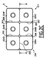
図2Aから図2Dは、それぞれ、本発明の第2実施形態に係る注入する工程の前の複数のプリフォームの上面図、当該複数のプリフォームの側断面図、注入する工程の完了時における複数の容器の上面図、当該複数の容器の側断面図である。 2A to 2D are respectively a top view of a plurality of preforms before an implantation step according to the second embodiment of the present invention, a side cross-sectional view of the plurality of preforms, and a plurality at the completion of the implantation step. FIG. 6 is a top view of the container, and a side sectional view of the plurality of containers.
図2Aは、均等に離間された2行×3列の配列で配置された容器200A,200B,200C,200D,200E及び200Fの配列Bの上面図である。プリフォーム200は、プリフォームの閉じられた端部の真下に配置される床202と、床202の外周から延びる壁203と、で成るトレイ201で表される包装要素内に配置されている。
FIG. 2A is a top view of an array B of
図2Bは、この配列の側断面図であり、図2Aに示されたA−A切断線に沿って取られている。プリフォーム200内への非圧縮性流体の注入の際に、トレイ201は、プリフォーム200の膨張を部分的に規制するように働き、壁203の上端から延びる領域においてプリフォームを自由に膨張させる。したがって、トレイ201は、続いて説明されるように、容器の製造システムの規制要素を形成する。
FIG. 2B is a cross-sectional side view of this arrangement, taken along the AA section line shown in FIG. 2A. Upon injection of the incompressible fluid into the
もちろん、トレイ201の構成は、単なる例示であり、他の実施形態ではより複雑であっても又は複雑でなくてもよく、したがって配置されるプリフォームの膨張をより規制しても又は規制しなくてもよい。
Of course, the configuration of the
実際に、トレイ201は、その表面の限定された特定の部分において膨張するプリフォームを規制するために複数のプリフォームに関して戦略的に配置される板、棒又はカップ等の他の規制要素によって、そのうえ補充又は置換されてもよい。この局所的な規制は、規制要素によって規定される特定の表面性状をともなう容器を製造するために、上記のプリフォーム相互の規制と協働する。
In fact, the
例えば、トレイ201には、膨張するプリフォームの底面の膨張のみを効率的に規制するように、高さが大幅に減少された壁203が付与されてもよく、又は、全体的に壁203が無くてさえもよい。したがって、結果として生じる容器には、平らな底部が設けられ、貯蔵及び使用を容易にする。
For example, the
他の可能な実施形態では、トレイ又は他のそのような規制要素はその表面上に、容器の膨張を規制し容器の表面に特定の模様又はパターンを押し付けるように構成された1つ又は複数の領域を更に備えてもよい。これは、例えば、識別を容易にするための製品ロゴ若しくはラベル、握り及び容器の強度を改善するための波形模様、節若しくはうね、又は、握り若しくは取っ手を提供するための刻み目若しくは肩を含んでもよい。そのような模様は、一般的な金属加工工程により模様付された簡単な板要素に設けられてもよく、複雑で高価な型ブロックを提供する必要なしに、複雑な表面輪郭及び模様をともなう容器のグループを製造し得る。 In other possible embodiments, the tray or other such restricting element is one or more configured on its surface to restrict the expansion of the container and press a particular pattern or pattern against the surface of the container. A region may be further provided. This includes, for example, product logos or labels to facilitate identification, wavy and corrugated patterns to improve the strength of the container, knots or ridges, or indentations or shoulders to provide grips or handles. But you can. Such patterns may be provided on simple plate elements patterned by common metalworking processes, and containers with complex surface contours and patterns without having to provide complex and expensive mold blocks A group of can be manufactured.
図2Cは、注入する工程の終了時における容器204A,204B,204C,204D,204E,204Fの配列Bの上面図である。ここから見られるように、容器204は、トレイ201の境界まで膨張しており、特に、先の実施形態のような接触表面205,206,207,208,209,210に沿った互いに対する当接への膨張に加えて、壁203によって規制されている。結果として生じる容器204は、ほぼ同一の形状及び輪郭を有する。
FIG. 2C is a top view of array B of
したがって、トレイ201の追加は、上記の本発明の利点を実現することに加えて、均一な輪郭の容器を製造することも可能にする。
Thus, the addition of the
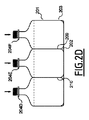
この実施形態では、容器204内に注入された液体は、その内部に保持及び密閉され、トレイ201は、包装211を集合的に備えるために容器204に関して維持される。これは、単一の工程で製造、充填及び包装された容器204のセットをもたらす。
In this embodiment, the liquid injected into the
具体的な実施形態に依存して、トレイ201又は他のそのような包装要素の構成は、変わってもよい。例えば、包装が消費者の使用に対して意図されている適用例では、トレイ201は、ほぼ本明細書に示された形状を採ることができ、一時使用のためのボール紙等の高価でない軽量な材料から製造され得る。随意に、トレイ201は、消費者への流通の準備が整った高価ではないが固い容器の束を作成するために、プラスチックフィルムの包装で補充されてもよい。
Depending on the specific embodiment, the configuration of the
代わりに、産業的、商業的又は社会事業的な状況において直面するような大量使用に対して容器が意図されている場合には、より強固で場合によっては再利用可能な形態で包装要素を提供することが有利であるかもしれない。そのような場合には、包装要素は、プラスチック又は金属の箱の形態で提供され得る。そのような耐久性のある構成で提供された包装要素は、そのような使用に固有の過酷さによく耐えることができる。 Instead, the packaging elements are provided in a stronger and possibly reusable form if the container is intended for high volume use as encountered in industrial, commercial or social business situations It may be advantageous to do. In such cases, the packaging element can be provided in the form of a plastic or metal box. Packaging elements provided in such a durable configuration can well withstand the rigors inherent in such use.
図2Dは、図2Cに示されるB−B切断線に沿った包装211及び容器の側断面図である。容器204D,204E,204Fは、接触表面209及び201での互いの当接へと膨張され、加えて、トレイ201の壁203及び床202によって規制されており、この図に示される平らな底部のほぼ四角形の形状を成す容器を結果としてもたらす。
2D is a side cross-sectional view of the
また、本実施形態では、複数の容器204は、ほぼ同じ大きさ及び形状であり、それぞれがほぼ同じ瞬間にほぼ同一量の非圧縮性流体で注入されており、したがってほぼ等しい程度に膨張するように誘導されている。しかしながら、他の実施では、異なる大きさ及び形状の容器を形成するために、異なる量の液体を注入することが好ましいかもしれない。この結果は、容器のいくつかに異なる液体を注入することによっても達成できる。
Also, in this embodiment, the plurality of
図3Aから図3Dは、それぞれ、本発明の第3実施形態に係る複数の容器の一連の製造工程の側断面図、上面図、及び2つの側断面図である。図3Aは、注入する工程の前の3つのプリフォーム300A,300B,300Cを示しており、プリフォーム300A,300B,300Cは、図2Aから図2Dのような規制要素301内で近接して配置されている。規制要素301は、先の実施形態のように外周から壁303が延びる床302を備える、ほぼ桶状の形状の凹部を有している。
3A to 3D are a side sectional view, a top view, and two side sectional views, respectively, of a series of manufacturing steps for a plurality of containers according to the third embodiment of the present invention. FIG. 3A shows three
さらに、規制要素301内でプリフォーム300の間に配置され、特別に構成された規制要素である形成インサート304が用意されている。形成インサート304は、プリフォーム300の上端付近から規制要素301の床302に向かって延びている。ここで、形成インサート304の形状について説明される。
In addition, a forming
図3Bは、注入する工程の前のプリフォーム300A,300B,300C,300D,300E及び300Fの上面図である。形成インサート304は、ウェブ306によって連結された星状の押出部305A及び305Bの形態の2つの主要部分を有することが見て取れる。
FIG. 3B is a top view of the preforms 300A, 300B, 300C, 300D, 300E, and 300F before the step of injecting. It can be seen that the forming
続く注入する工程の際に、プリフォーム300は、ここでは破線で示される容器306A,306B,306C,306D,306E,306Fへと膨張される。星状の押出部305A,305B及びウェブ306は、容器306の最終形状を部分的に規定するように働く。しかしながら、それにもかかわらず、プリフォームが膨張するにつれて、プリフォームは、形成インサート304が存在しない当接部、具体的には、容器306A及び306Dの間、容器306C及び306Fの間、容器306A及び306Bの間、容器306B及び306Cの間、容器306D及び306Eの間、並びに、容器306E及び306Fの間の境界面で、互いに当接する。
During the subsequent pouring step, the
このようにして、容器の間の(ここでは、形成インサート304により占められている)領域における容器の形状を規定できる一方で、それにもかかわらず、非圧縮性流体の注入の際のプリフォーム相互の当接の利益を実現できる。もちろん、形成インサートは、任意の特定の適用例の状況によって要求されるように、他の形状にある他の形態で提供されてもよい。 In this way, the shape of the container in the region between the containers (here occupied by the forming insert 304) can be defined, but nevertheless the preforms during incompressible fluid injection The abutment benefits can be realized. Of course, the forming insert may be provided in other forms in other shapes, as required by the circumstances of any particular application.
図3Cは、注入する工程の終了時であって取り外す工程の前の容器306の側面図である。形成インサート304は容器306の間に配置されたままであり、容器は非圧縮性流体の注入の後の最終形状を成している。形成インサート304は、容器306及び規制要素301の集合体にある程度の構造的強度を付加し、また、同じ装置において容器が密閉されず、ラベルが貼られず、又は、包まれない適用例においては、容器306が製造の際に移送されている間は、一時的に、所定の位置に規制要素304を残すことが有利であるかもしれない。
FIG. 3C is a side view of the
図3Dは取り外す工程を示しており、形成インサート304が容器306から取り外されている。次いで、容器306は、規制要素301から取り除かれてもよく、規制要素301が包装要素である場合には規制要素と共に流通されてもよい。次いで、形成インサート304は、次の反復工程で再利用されてもよい。形成インサート304は、容器製造装置の一体構成要素として設けられることが好ましいが、しかしながら、代わりに、容器製造装置により操作されるが一体化されていない取り外し可能な要素の形態で提供されてもよい。ユーザは、任意の特定の実施に対して適切な構成を決定することができる。
FIG. 3D shows the removal process, with the forming
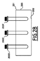
図4は、本発明の第4実施形態に係る、装置として言及されることもある、システム400を示しており、全体的に、規制要素401Aと、注入要素401Bと、を備えている。なお、この図は、4つのそのような規制要素のうちの1つのみを示していることに留意されたい。他の3つは明瞭のために省略されているが、規制要素401Aとほぼ同様である。
FIG. 4 shows a
規制要素401Aは、それぞれプリフォーム403A,403B,403Cが配置される3つのチャンバ402A,402B,402Cを備えている。チャンバ402は、互いに隣接している。チャンバ402A及び402Bの交差部は、峰404により規定されており、チャンバ402B及び402の交差部は、峰405により規定されている。
The restricting
なお、峰404及び405は、規制要素400の端部406に至るまでは延びていないことに留意されたい。規制要素400が反対に配置された同一の規制要素で閉じられた場合、隙間407及び408が形成され、それぞれチャンバ402A及び402Bの間、並びにチャンバ402B及び402Cの間の流体連通を確立する。
Note that the
したがって、プリフォーム403内への非圧縮性流体の注入の際に、プリフォーム403は、隙間407及び408内に膨張する。プリフォーム403Aは、峰404の領域内で、隙間407を通してプリフォーム403Bと当接し、同様に、プリフォーム403Cは、峰405に沿って、隙間408を通してプリフォーム403Bと当接する。特に、非圧縮性流体の注入及びプリフォーム403の予熱のパラメータを変化させることによって、当接している表面で互いに軽く付着した複数の容器を製造し得る。
Accordingly, the
このようにして、システム又は装置400は、当接する表面で互いに結合された複数の容器の補完体を製造する。よって、ユーザは、互いに付着ししたがって容易に移送されるが他の容器及び消費される中身から簡単に分離できる複数の容器の束を製造し得る。この目的のため、当接部の圧力及び/若しくは大きさ、プリフォームの温度、並びに/又は、プリフォームの材料が、複数の製造された容器の平均的最終消費者によって製造された容器が互いに取り外し可能となるように、決定できる。
In this way, the system or
そのような束は、具体的には、いくつかの簡単に持ち運びできる例えば飲み物の容器を有することが好ましいピクニックでの使用又は旅行時等に便利である。 Such a bundle is particularly convenient for use on a picnic or when traveling, for example, where it is preferred to have a number of easily portable containers such as drinks.
システム又は装置400はまた、注入要素401Bを備える。注入要素401Bは、全体的に、複数のノズル409を備える。ノズル409は、上部フレーム410及び下部フレーム411によって互いに関連して保持されており、すなわち、複数のノズル409のうちの複数のノズルは互いに関連した位置及び方向で固定されている。上部フレーム410及び下部フレーム411は、それぞれ、縦部材412及び413、並びに横部材414及び415を備える。縦部材412及び413、並びに横部材414及び415は、複数のノズル409の間を延びており、複数のノズルを互いに対して固定された方向に保持している。
The system or
複数のノズル409は、1つの液体を収容する少なくとも1つの加圧液体源と、順番にプリフォームに上記の液体を注入する各ノズルに圧力下の上記の液体を配送するように構成された加圧手段と、流体連通している。ある実施形態によれば、複数のノズル409のうちの複数のノズルは、同じ加圧液体源に全てが接続されているわけではない。これは、複数のノズル409のうち、少なくとも1つの第1のノズルは、又は複数の第1のノズルのグループは、第1の液体を収容する第1の加圧液体源と流体連通しており、同じ複数のノズル409のうち、少なくとも1つの第2のノズルは、又は複数の第2のノズルのグループは、第1の液体とは異なる第2の液体を収容する第2の加圧流体源と流体連通していることを意味する。このようにして、第1の液体が、1つ又は複数の第1のノズルが係合された1つ又は複数のプリフォーム内に注入され、第2の液体が、1つ又は複数の第2のノズルが係合された1つ又は複数のプリフォーム内に注入される。結果として、同じ複数の容器のうちの複数の容器が、同じ容器の形成及び充填工程において、異なる液体で充填できる。2つより多い加圧液体源を提供できることが理解されるべきである。具体的には、各ノズルは、同じ複数の容器のうちの複数の容器がそれぞれ異なる液体で充填されるように、異なる加圧液体源と流体連通することができる。
The plurality of
なお、規制要素401Aは、集合的にチャンバ402A,402B,402Cによって成る領域402の境界を定めることに留意すべきである。領域402の大きさ、形状及び形態を変えることにより、装置400によって製造される容器の最終形状を変えてもよい。
It should be noted that the restricting
対照的に、注入要素401Bは、規制要素401Aに対して移動可能であり、ノズル409が製造工程の際にプリフォーム内に非圧縮性流体を注入するようにプリフォーム403に係合し、次いで結果として生じた容器を取り除けるように解放されることを可能にする。
In contrast, the
また、注入要素401Bがプリフォーム403の間の異なる距離に適合できるように、縦部材412及び413、並びに横部材414及び415を可変長さの構成で用意することが有利であるかもしれない。そのような可変長さの構成の縦部材412及び413、並びに横部材414及び415は、機械技術分野において知られている方法で達成されてもよく、例えば、親ねじ、又は空圧若しくは油圧シリンダーを用いることである。どのような手段が用いられても、縦部材412及び413、並びに横部材414及び415の長さは、注入する工程の開始の前には固定されており、これによりノズル409を互いに対して固定された方向及び位置に置くことができる。
It may also be advantageous to provide the
同様に、他の適用例に対して、図3Aから図3Dに示されたもののような形成インサートを供給することが有利であるかもしれない。当業者は、そのような形成インサートを組み込むように装置を構成することができる。 Similarly, for other applications, it may be advantageous to provide a forming insert such as that shown in FIGS. 3A-3D. One skilled in the art can configure the apparatus to incorporate such forming inserts.
このようにして、ユーザは、異なる容量の容器を製造するようにシステム又は装置400を適合してもよく、これにより商業的適用例において装置400の生産性を最適化してもよい。
In this way, the user may adapt the system or
図5は、本発明の第5実施形態に係る容器501の束500を示している。容器501は、ここでは、各列が6つの容器501を含む2つの列502として提供されている。もちろん、他の配列が可能であり、より多くの又はより少ない列で配列された、及び場合によっては異なる大きさ及び容量である、より多くの又はより少ない容器を備えていてもよい。
FIG. 5 shows a
容器501はさらに、単一で取り扱いが簡単な束に容器501を一緒に束ねる働きをする、包装503内に含まれている。包装503は、ここでは、熱収縮性プラスチックのシートの形態で提供されているが、もちろん、容器製造技術分野及び関連する技術分野で知られている他の形態及び他の材料で提供されてもよい。
The
この実施形態では、容器501は、同じサイズ、形状及び容量であり、2つの列502の形態で提供されている。これは、容器501を製造するために1つの装置のみが用いられる必要がある点で有利である。2つの列502の容器501は、本発明の方法の2つの反復に相当する、そのような装置の2つの操作サイクルで製造される。
In this embodiment, the
しかしながら、他の実施形態では、サイズ、容量、形状、及び/又は数量の異なる容器のグループを結合することが有利であり得、構成された束において、これらの性状の様々な異なる有利な結合が達成される。したがって、ユーザは、より大きな柔軟性を実現できる。 However, in other embodiments, it may be advantageous to combine groups of containers of different sizes, volumes, shapes, and / or quantities, and in the configured bundle there are various different advantageous combinations of these properties. Achieved. Therefore, the user can realize greater flexibility.
容器501にはさらに、それぞれラベル504が設けられる。ラベル504は、容器の製造の終了の後に実行されるラベルを貼る工程において、貼り付けられてもよい。代わりに、ラベル504は、規制要素の表面上に配置されてもよく、これにより、注入する工程の際にプリフォームがラベルに対して押し付けられ、注入する工程と同時のラベルを貼る工程において、結果として生じる容器501にラベルが付着する。
Each
この後者の構成は、上記の装置又はシステムと合わせて用いられる場合に、ユーザが、単一の装置において単一の工程で製造、充填、及びラベルが貼られる容器を製造できるという点で、特に有利である。したがって、ユーザは、生産性を増大させ、製造設備に必要な物理的空間を低減できるという形で、顕著な利点を達成できる。 This latter configuration, particularly when used in conjunction with the devices or systems described above, is particularly advantageous in that users can manufacture containers that are manufactured, filled, and labeled in a single process on a single device. It is advantageous. Thus, the user can achieve significant advantages in the form of increased productivity and reduced physical space required for manufacturing equipment.
図6は、本発明の第6実施形態に係る容器601の束600を示している。束600は、図5に示される束と同様であり、すなわち、容器601は、同じ大きさ、形状及び容量であり、包装603内に含まれる2つの列602の形態で提供されており、それぞれが蓋605で閉じられている。相違点は、異なるラベル607,608,609が異なる容器601に貼り付けられるという点である。これは、ラベルを貼る工程が、1つの第1の容器601に、又は複数の第1の容器601のグループに第1のラベル607を貼る工程と、1つの第2の容器601に、又は複数の第2の容器601のグループに第2のラベル608を貼る工程と、場合によっては、1つの第3の容器に、又は複数の第3の容器601のグループに第3のラベル609を貼る工程と、を備えることを意味する。特定の実施形態によれば、各容器には、異なるラベルが設けられる。この実施形態は、上記のように容器が異なる液体で充填されるときに、特に有利である。このようにして、容器に含まれる様々な液体が、容器に貼られた適切な異なるラベルによって、識別可能である。
FIG. 6 shows a bundle 600 of
上記のシステムは、図7に示されるような一工程型システム700として実施可能である。そのようなシステムは、熱可塑性原材料源703からプリフォーム702を製造するように構成されたプリフォーム製造装置701を備える。プリフォームは、例えば、それ自体は知られている注入処理を用いたバッチ処理により製造される。プリフォーム製造装置701に存在する製造されたプリフォームは、それぞれがプリフォームを保持するように構成された複数のプリフォーム保持装置704によって取り出され、移送装置705が、プリフォーム保持装置704に関連付けられた各製造されたプリフォーム702を規制要素706内に移送する。規制要素706は、上記の任意の実施形態にしたがって構成することができる。一旦、全てのプリフォーム702が規制要素706内に装填されると、プリフォーム702は適切な保持手段によって規制要素706内に保持され、複数のノズル707がプリフォーム702内に係合され、容器708が液体によって形成され充填される。システム700の出口では、複数の容器708が得られる。上記のように、複数の容器707が、単一の工程で得られた束として得られることができ、各容器が、単一の液体又は異なる液体で充填され、例えばプリフォーム内への液体の注入の際に容器に貼られる同一の又は異なるラベルが貼られる。
The above system can be implemented as a one-
追加的に又は選択的に、システム700は、例えば線形型のシステムであり、規制要素706内のプリフォーム702、及び複数のノズル707が、図7の矢印Fで示されるように、プリフォーム内への液体の注入の際に、回転することなしに、移送の際に一緒に移動される。
Additionally or alternatively, the
そのようなシステムは、大きな空間を必要としないシステム内において、平行に容器の複数の束を高速で製造することを可能にする。 Such a system allows high speed production of multiple bundles of containers in parallel in a system that does not require a large amount of space.
本発明が例示により説明されたが、特許請求の範囲により定義される本発明の範囲から逸脱することなく、変形及び改良がなされてもよいことが理解されるべきである。また、特定の要素に対して既知の均等物が存在する場合には、そのような均等物は、本明細書内で具体的に言及されているかのように組み込まれる。 Although the invention has been described by way of example, it is to be understood that variations and modifications may be made without departing from the scope of the invention as defined by the claims. Also, where there are known equivalents for a particular element, such equivalents are incorporated as if specifically recited in the specification.
Claims (23)
それぞれが空洞(102A,102B,102C)を画定する複数のプリフォーム(100,200,300,403)を提供する工程であって、各プリフォーム(100,200,300,403)が、少なくとも1つの他のプリフォーム(100,200,300,403)からその直径の2倍から10倍の間の距離で配置される、工程と、
前記複数のプリフォームが前記複数の容器(105,204,306,501)へと膨張することを誘導するように、各プリフォーム(100,200,300,403)の前記空洞(102A,102B,102C)内にある量の非圧縮性流体(106)を注入する工程と、を備え、
注入する工程の際に、各容器(105,204,306,501)の表面の当接部が、少なくとも1つの他の容器(105,204,306,501)の表面の当接部と当接し、これにより、前記容器(105,204,306,501)の前記膨張が規制されることを特徴とする、複数の容器の製造方法。 A method of manufacturing a plurality of containers (105, 204, 306, 501),
Providing a plurality of preforms (100, 200, 300, 403) each defining a cavity (102A, 102B, 102C), wherein each preform (100, 200, 300, 403) is at least one Being disposed at a distance between two and ten times its diameter from two other preforms (100, 200, 300, 403);
The cavities (102A, 102B,...) Of each preform (100, 200, 300, 403) so as to induce the plurality of preforms to expand into the plurality of containers (105, 204, 306, 501). 102C) injecting an amount of incompressible fluid (106) within
During the injection process, the contact portion of the surface of each container (105, 204, 306, 501) contacts the contact portion of the surface of at least one other container (105, 204, 306, 501). This restricts the expansion of the containers (105, 204, 306, 501), and a method for manufacturing a plurality of containers.
1つの液体を収容する少なくとも1つの加圧液体源及び圧力下の前記液体を配送するように構成された加圧手段と、
複数のプリフォーム(403)と、
それぞれが前記複数のプリフォームのうちの1つのプリフォームと対になり、前記プリフォームが容器へと膨張され同時に前記容器が液体で充填されるように前記プリフォームの空洞内に圧力下の前記液体を注入するために、それぞれが前記少なくとも1つの加圧源と流体連通する、複数のノズル(409)と、
前記複数のプリフォームを受容する少なくとも1つの規制要素(401)と、を備え、
前記少なくとも1つの規制要素は、あるプリフォームの少なくとも当接部が、他のプリフォームの当接部と、当該あるプリフォーム及び当該他のプリフォームの双方が容器へと膨張する際に、当接することを可能にするように構成された、システム。 A system for manufacturing a plurality of containers and filling each container of the plurality of containers with a liquid,
At least one pressurized liquid source containing one liquid and pressurizing means configured to deliver the liquid under pressure;
A plurality of preforms (403);
Each of which is paired with one of the plurality of preforms, the preform under pressure in the cavity of the preform such that the preform is expanded into a container and at the same time the container is filled with liquid A plurality of nozzles (409), each in fluid communication with the at least one pressure source, for injecting liquid;
And at least one regulatory element (401) for receiving the plurality of preforms,
The at least one restricting element is configured so that at least a contact portion of a certain preform is in contact with a contact portion of another preform and when both the certain preform and the other preform expand into the container. A system that is configured to allow contact.
プリフォーム製造装置と、
複数のプリフォーム保持装置と、
プリフォーム保持装置と関連付けられた製造された各プリフォームを規制要素内に移送するように構成された移送装置と、を備える、
請求項15〜22のいずれか一項に記載のシステム。 The system is a one-step type,
Preform manufacturing equipment;
A plurality of preform holding devices;
A transfer device configured to transfer each manufactured preform associated with the preform holding device into the restriction element;
The system according to any one of claims 15 to 22.
Applications Claiming Priority (3)
| Application Number | Priority Date | Filing Date | Title |
|---|---|---|---|
| EP13197336.4A EP2883680A1 (en) | 2013-12-16 | 2013-12-16 | A method and apparatus for fabricating containers |
| EP13197336.4 | 2013-12-16 | ||
| PCT/EP2014/078081 WO2015091565A1 (en) | 2013-12-16 | 2014-12-16 | A method and apparatus for fabricating containers |
Publications (2)
| Publication Number | Publication Date |
|---|---|
| JP2017501062A JP2017501062A (en) | 2017-01-12 |
| JP6495936B2 true JP6495936B2 (en) | 2019-04-03 |
Family
ID=49880409
Family Applications (2)
| Application Number | Title | Priority Date | Filing Date |
|---|---|---|---|
| JP2016558278A Active JP6636940B2 (en) | 2013-12-16 | 2014-12-16 | Container manufacturing method and manufacturing apparatus |
| JP2016558279A Active JP6495936B2 (en) | 2013-12-16 | 2014-12-16 | Container manufacturing method and manufacturing apparatus |
Family Applications Before (1)
| Application Number | Title | Priority Date | Filing Date |
|---|---|---|---|
| JP2016558278A Active JP6636940B2 (en) | 2013-12-16 | 2014-12-16 | Container manufacturing method and manufacturing apparatus |
Country Status (5)
| Country | Link |
|---|---|
| US (2) | US10500780B2 (en) |
| EP (3) | EP2883680A1 (en) |
| JP (2) | JP6636940B2 (en) |
| CN (2) | CN105829063B (en) |
| WO (2) | WO2015091565A1 (en) |
Families Citing this family (10)
| Publication number | Priority date | Publication date | Assignee | Title |
|---|---|---|---|---|
| EP2883680A1 (en) * | 2013-12-16 | 2015-06-17 | Discma AG | A method and apparatus for fabricating containers |
| US10800780B2 (en) * | 2015-12-24 | 2020-10-13 | Genentech, Inc. | TDO2 Inhibitors |
| JP6835498B2 (en) * | 2016-07-22 | 2021-02-24 | 株式会社吉野工業所 | Container manufacturing method by liquid blow molding |
| JP6792974B2 (en) | 2016-07-22 | 2020-12-02 | 株式会社吉野工業所 | Container manufacturing method by liquid blow molding |
| EP3737546A4 (en) | 2018-01-11 | 2021-11-17 | Husky Injection Molding Systems Luxembourg IP Development S.à.r.l | Method and apparatus for forming final-shaped containers using liquid to be contained therein |
| WO2020002993A1 (en) * | 2018-06-29 | 2020-01-02 | Discma Ag | Free blow bottle design |
| EP3814096A1 (en) * | 2018-06-29 | 2021-05-05 | Discma AG | Blowing station and method for forming a free blow container |
| US10604292B1 (en) * | 2019-02-20 | 2020-03-31 | Gravitron, LLC | System, method and apparatus for processing cartridges en masse |
| JP7345417B2 (en) | 2020-03-26 | 2023-09-15 | 株式会社吉野工業所 | liquid blow molding equipment |
| KR102148700B1 (en) * | 2020-07-10 | 2020-08-27 | 박수경 | Equipment for Manufacturing Reagent Containers of Various Sizes |
Family Cites Families (40)
| Publication number | Priority date | Publication date | Assignee | Title |
|---|---|---|---|---|
| US2013382A (en) | 1933-11-04 | 1935-09-03 | Carr Lowrey Glass Co | Method of making multiple bottles |
| US3206020A (en) * | 1963-04-09 | 1965-09-14 | Du Pont | Multiple container package |
| US3374917A (en) * | 1964-01-09 | 1968-03-26 | Constantine T. Troy | Interlocking structural elements |
| US3391824A (en) * | 1964-06-19 | 1968-07-09 | Rexall Drug Chemical | Stacking container |
| JPS4972362A (en) * | 1972-11-10 | 1974-07-12 | ||
| US4235343A (en) * | 1979-07-30 | 1980-11-25 | Thompson Harold E | Container assembly |
| US4570799A (en) * | 1984-02-06 | 1986-02-18 | Universal Symetrics Corporation | Multiple container package |
| US4872557A (en) * | 1985-01-30 | 1989-10-10 | Transphase Systems, Inc. | Nestable, stackable containers |
| US4656840A (en) * | 1985-11-29 | 1987-04-14 | Gott Corporation | Container for freezable liquid |
| US4696403A (en) * | 1986-09-16 | 1987-09-29 | Sonoco Products Company | Bottle bag |
| US4875620A (en) * | 1988-11-02 | 1989-10-24 | W. A. Lane, Inc. | Fluted product cup |
| US5135702A (en) * | 1990-09-04 | 1992-08-04 | Eales George E | Extrusion blow molding process for forming multi-compartment containers |
| CA2051577A1 (en) * | 1990-10-31 | 1992-05-01 | Norwin C. Derby | Variable diameter hollow extruded articles and method of manufacture |
| SE9302822D0 (en) * | 1993-09-01 | 1993-09-01 | Haakan Edqvist | Package and method for producing said package |
| JP2876992B2 (en) * | 1994-06-21 | 1999-03-31 | 東洋製罐株式会社 | Manufacturing method of biaxially stretched blow container |
| US5573143A (en) * | 1994-09-21 | 1996-11-12 | Colgate-Palmolive Company | Blow molded multi-chamber containers with dispenser/doser |
| US5782376A (en) * | 1995-05-25 | 1998-07-21 | General Mills, Inc. | Thermoformed plastic containers and their method of manufacture |
| US5823391A (en) * | 1996-09-04 | 1998-10-20 | Owens-Brockway Plastic Products Inc. | Dual chamber flexible tube dispensing package and method of making |
| US6355204B1 (en) * | 2000-06-07 | 2002-03-12 | Owens-Brockway Plastic Products Inc. | Method of manufacturing a dual-chamber container |
| IT1316905B1 (en) * | 2000-06-15 | 2003-05-13 | Lameplast Spa | PARTICULARLY FOLDABLE CONTAINER FOR FLUID PRODUCTS. |
| JP2002362526A (en) * | 2001-04-04 | 2002-12-18 | Nippo Corp | Continuous resin molded container and manufacturing method therefor |
| US6601725B2 (en) * | 2001-05-15 | 2003-08-05 | 3088081 Canada, Inc. | Integral assembly of reagent tubes and seal caps |
| CA2414714A1 (en) * | 2002-01-04 | 2003-07-04 | The Pillsbury Company | Trays for sauces, products containing same and methods |
| US20040164076A1 (en) * | 2002-06-18 | 2004-08-26 | Baker Loren G. | Lidded container with linear brim segments and medial sealing beads |
| FR2848906B1 (en) * | 2002-12-23 | 2006-08-18 | Sidel Sa | METHOD AND INSTALLATION FOR MANUFACTURING A CONTAINER OF PLASTIC MATERIAL |
| US20070045213A1 (en) * | 2005-08-15 | 2007-03-01 | Plastipak Packaging, Inc. | Stackable plastic container |
| US7845147B2 (en) * | 2006-02-20 | 2010-12-07 | Frito-Lay North America, Inc. | Method for producing a detachably connected container having barrier properties |
| US7549551B2 (en) * | 2006-04-04 | 2009-06-23 | Anchor Packaging | Multi-cellular container with cut-score |
| US8573964B2 (en) * | 2006-04-13 | 2013-11-05 | Amcor Limited | Liquid or hydraulic blow molding |
| EP2143542A1 (en) | 2008-07-07 | 2010-01-13 | Nestec S.A. | Method and apparatus for packaging a liquid food product |
| US20100065562A1 (en) * | 2008-09-16 | 2010-03-18 | Terry Vovan | Detachable food package |
| JP5363911B2 (en) * | 2009-08-17 | 2013-12-11 | 株式会社フジシールインターナショナル | Container set |
| JP2011121640A (en) * | 2009-12-09 | 2011-06-23 | Keiji Kizu | Concentrating-type pet bottle container |
| EP2463209A1 (en) * | 2010-12-10 | 2012-06-13 | Nestec S.A. | Secondary packaging comprising multiple primary packaging sizes |
| CN103608164B (en) | 2011-06-09 | 2015-12-02 | 帝斯克玛股份有限公司 | For the bucking-out system of the use isolation cylinder of Hydrapak machinery |
| JP2013043675A (en) * | 2011-08-24 | 2013-03-04 | Fuji Seal International Inc | Package |
| WO2013063461A1 (en) * | 2011-10-27 | 2013-05-02 | Amcor Limited | Counter stretch connecting rod and positive fill level control rod |
| EP2810763B1 (en) | 2012-01-31 | 2018-03-07 | Discma AG | Blow molding device |
| WO2014001099A1 (en) * | 2012-06-27 | 2014-01-03 | Nestec S.A. | Method and apparatus for the fabrication of a container, such as a beverage container |
| EP2883680A1 (en) * | 2013-12-16 | 2015-06-17 | Discma AG | A method and apparatus for fabricating containers |
-
2013
- 2013-12-16 EP EP13197336.4A patent/EP2883680A1/en not_active Withdrawn
- 2013-12-16 EP EP14177674.0A patent/EP2883681B1/en active Active
-
2014
- 2014-12-16 EP EP14821583.3A patent/EP3083189B1/en active Active
- 2014-12-16 CN CN201480068252.6A patent/CN105829063B/en active Active
- 2014-12-16 JP JP2016558278A patent/JP6636940B2/en active Active
- 2014-12-16 US US15/105,421 patent/US10500780B2/en active Active
- 2014-12-16 WO PCT/EP2014/078081 patent/WO2015091565A1/en active Application Filing
- 2014-12-16 WO PCT/EP2014/078078 patent/WO2015091562A1/en active Application Filing
- 2014-12-16 CN CN201480068705.5A patent/CN105829064B/en active Active
- 2014-12-16 US US15/104,805 patent/US10166712B2/en active Active
- 2014-12-16 JP JP2016558279A patent/JP6495936B2/en active Active
Also Published As
| Publication number | Publication date |
|---|---|
| WO2015091565A1 (en) | 2015-06-25 |
| CN105829064B (en) | 2018-04-06 |
| EP3083189B1 (en) | 2017-12-13 |
| CN105829063A (en) | 2016-08-03 |
| JP2017501061A (en) | 2017-01-12 |
| EP3083189A1 (en) | 2016-10-26 |
| US20160318228A1 (en) | 2016-11-03 |
| US10166712B2 (en) | 2019-01-01 |
| US20160318229A1 (en) | 2016-11-03 |
| EP2883681B1 (en) | 2018-09-12 |
| EP2883681A1 (en) | 2015-06-17 |
| US10500780B2 (en) | 2019-12-10 |
| CN105829064A (en) | 2016-08-03 |
| WO2015091562A1 (en) | 2015-06-25 |
| JP2017501062A (en) | 2017-01-12 |
| EP2883680A1 (en) | 2015-06-17 |
| JP6636940B2 (en) | 2020-01-29 |
| CN105829063B (en) | 2018-06-19 |
Similar Documents
| Publication | Publication Date | Title |
|---|---|---|
| JP6495936B2 (en) | Container manufacturing method and manufacturing apparatus | |
| US20060097417A1 (en) | Method and installation for the production of a plastic container | |
| CA2641369C (en) | Apparatus and method for the production of bimaterial hollow bodies by means of injection overmoulding | |
| US9211668B2 (en) | Receiving system | |
| US20100308043A1 (en) | Bodies, packages of bodies, and a device and method for packaging bodies | |
| GB2422571A (en) | Moulding of plastics articles | |
| EP2780146B1 (en) | Plural blow utilization of counter stretch rod and/or base pushup | |
| CN108602230B (en) | Injection and blow mould for injection moulding machine | |
| US20120018928A1 (en) | Method and apparatus for producing tiered containers | |
| US20230191672A1 (en) | Method and device for making a multi component product | |
| EP2097322B1 (en) | Container, apparatus and method for producing a container | |
| US8678810B2 (en) | Apparatus and method for the production of bi-material hollow bodies by means of injection overmolding | |
| WO2005110861A1 (en) | Stretch blow molding method for grippable bottle | |
| US20130142974A1 (en) | Plastics preform for large-volume containers and process and device for producing this preform | |
| EP2554355A1 (en) | Apparatus and method for manufacturing containers | |
| US4230298A (en) | Apparatus for the preparation of hollow plastic articles | |
| US20090045549A1 (en) | Equipment and method for producing thermoformed and heat-sealed containers | |
| DE102007037536A1 (en) | Process for producing tube-like bodies and a tube-like body | |
| RU2407636C2 (en) | Device and method of producing hollow cases made of two materials by multi-component injection moulding | |
| JP7321376B2 (en) | Method of manufacturing container preforms using additive manufacturing | |
| EP3479995B1 (en) | Container manufacturing method | |
| CN112938868A (en) | Sterile blowing and filling equipment and sterile blowing and filling method |
Legal Events
| Date | Code | Title | Description |
|---|---|---|---|
| A621 | Written request for application examination |
Free format text: JAPANESE INTERMEDIATE CODE: A621 Effective date: 20171006 |
|
| A977 | Report on retrieval |
Free format text: JAPANESE INTERMEDIATE CODE: A971007 Effective date: 20181024 |
|
| A131 | Notification of reasons for refusal |
Free format text: JAPANESE INTERMEDIATE CODE: A131 Effective date: 20181030 |
|
| A521 | Request for written amendment filed |
Free format text: JAPANESE INTERMEDIATE CODE: A523 Effective date: 20181214 |
|
| TRDD | Decision of grant or rejection written | ||
| A01 | Written decision to grant a patent or to grant a registration (utility model) |
Free format text: JAPANESE INTERMEDIATE CODE: A01 Effective date: 20190205 |
|
| A61 | First payment of annual fees (during grant procedure) |
Free format text: JAPANESE INTERMEDIATE CODE: A61 Effective date: 20190307 |
|
| R150 | Certificate of patent or registration of utility model |
Ref document number: 6495936 Country of ref document: JP Free format text: JAPANESE INTERMEDIATE CODE: R150 |
|
| R250 | Receipt of annual fees |
Free format text: JAPANESE INTERMEDIATE CODE: R250 |
|
| R250 | Receipt of annual fees |
Free format text: JAPANESE INTERMEDIATE CODE: R250 |
|
| R250 | Receipt of annual fees |
Free format text: JAPANESE INTERMEDIATE CODE: R250 |