JP6494644B2 - Multipurpose and aesthetically improved barrel dispensing device - Google Patents
Multipurpose and aesthetically improved barrel dispensing device Download PDFInfo
- Publication number
- JP6494644B2 JP6494644B2 JP2016550667A JP2016550667A JP6494644B2 JP 6494644 B2 JP6494644 B2 JP 6494644B2 JP 2016550667 A JP2016550667 A JP 2016550667A JP 2016550667 A JP2016550667 A JP 2016550667A JP 6494644 B2 JP6494644 B2 JP 6494644B2
- Authority
- JP
- Japan
- Prior art keywords
- spout
- barrel
- dispensing device
- upper column
- door
- Prior art date
- Legal status (The legal status is an assumption and is not a legal conclusion. Google has not performed a legal analysis and makes no representation as to the accuracy of the status listed.)
- Active
Links
- 235000013361 beverage Nutrition 0.000 claims description 46
- 230000007246 mechanism Effects 0.000 claims description 19
- 239000007788 liquid Substances 0.000 claims description 15
- 238000001816 cooling Methods 0.000 description 46
- 239000003570 air Substances 0.000 description 32
- XLYOFNOQVPJJNP-UHFFFAOYSA-N water Substances O XLYOFNOQVPJJNP-UHFFFAOYSA-N 0.000 description 24
- 239000007789 gas Substances 0.000 description 16
- 238000000034 method Methods 0.000 description 13
- IJGRMHOSHXDMSA-UHFFFAOYSA-N Atomic nitrogen Chemical compound N#N IJGRMHOSHXDMSA-UHFFFAOYSA-N 0.000 description 12
- 235000013405 beer Nutrition 0.000 description 12
- 238000005034 decoration Methods 0.000 description 7
- 238000013461 design Methods 0.000 description 7
- 230000006378 damage Effects 0.000 description 6
- 229910052757 nitrogen Inorganic materials 0.000 description 6
- 230000035622 drinking Effects 0.000 description 5
- 238000005187 foaming Methods 0.000 description 5
- CURLTUGMZLYLDI-UHFFFAOYSA-N Carbon dioxide Chemical compound O=C=O CURLTUGMZLYLDI-UHFFFAOYSA-N 0.000 description 4
- 235000014171 carbonated beverage Nutrition 0.000 description 4
- 239000011521 glass Substances 0.000 description 4
- 239000003507 refrigerant Substances 0.000 description 4
- 239000011800 void material Substances 0.000 description 4
- 208000027418 Wounds and injury Diseases 0.000 description 3
- 239000012080 ambient air Substances 0.000 description 3
- 230000008901 benefit Effects 0.000 description 3
- 239000006260 foam Substances 0.000 description 3
- 208000014674 injury Diseases 0.000 description 3
- 238000009413 insulation Methods 0.000 description 3
- 230000008569 process Effects 0.000 description 3
- 235000014101 wine Nutrition 0.000 description 3
- XKRFYHLGVUSROY-UHFFFAOYSA-N Argon Chemical compound [Ar] XKRFYHLGVUSROY-UHFFFAOYSA-N 0.000 description 2
- 230000005679 Peltier effect Effects 0.000 description 2
- 230000009286 beneficial effect Effects 0.000 description 2
- 229910002092 carbon dioxide Inorganic materials 0.000 description 2
- 239000001569 carbon dioxide Substances 0.000 description 2
- 238000009826 distribution Methods 0.000 description 2
- 230000000694 effects Effects 0.000 description 2
- 239000012530 fluid Substances 0.000 description 2
- 238000012423 maintenance Methods 0.000 description 2
- 238000012986 modification Methods 0.000 description 2
- 230000004048 modification Effects 0.000 description 2
- 238000005057 refrigeration Methods 0.000 description 2
- 238000009423 ventilation Methods 0.000 description 2
- 241000282693 Cercopithecidae Species 0.000 description 1
- LFQSCWFLJHTTHZ-UHFFFAOYSA-N Ethanol Chemical compound CCO LFQSCWFLJHTTHZ-UHFFFAOYSA-N 0.000 description 1
- CDBYLPFSWZWCQE-UHFFFAOYSA-L Sodium Carbonate Chemical compound [Na+].[Na+].[O-]C([O-])=O CDBYLPFSWZWCQE-UHFFFAOYSA-L 0.000 description 1
- 241000234314 Zingiber Species 0.000 description 1
- 235000006886 Zingiber officinale Nutrition 0.000 description 1
- 230000009471 action Effects 0.000 description 1
- 230000002411 adverse Effects 0.000 description 1
- 235000013334 alcoholic beverage Nutrition 0.000 description 1
- 239000002518 antifoaming agent Substances 0.000 description 1
- 229910052786 argon Inorganic materials 0.000 description 1
- 235000019987 cider Nutrition 0.000 description 1
- 238000004140 cleaning Methods 0.000 description 1
- 239000003086 colorant Substances 0.000 description 1
- 238000004891 communication Methods 0.000 description 1
- 230000006835 compression Effects 0.000 description 1
- 238000007906 compression Methods 0.000 description 1
- 238000005265 energy consumption Methods 0.000 description 1
- 238000001704 evaporation Methods 0.000 description 1
- 230000008020 evaporation Effects 0.000 description 1
- 238000001914 filtration Methods 0.000 description 1
- 238000007710 freezing Methods 0.000 description 1
- 230000008014 freezing Effects 0.000 description 1
- 235000008397 ginger Nutrition 0.000 description 1
- 238000010438 heat treatment Methods 0.000 description 1
- 239000004615 ingredient Substances 0.000 description 1
- 230000010354 integration Effects 0.000 description 1
- 230000000670 limiting effect Effects 0.000 description 1
- 239000004973 liquid crystal related substance Substances 0.000 description 1
- 239000000463 material Substances 0.000 description 1
- 230000003278 mimic effect Effects 0.000 description 1
- 239000000203 mixture Substances 0.000 description 1
- 238000003825 pressing Methods 0.000 description 1
- 230000035755 proliferation Effects 0.000 description 1
- 230000002035 prolonged effect Effects 0.000 description 1
- 235000021580 ready-to-drink beverage Nutrition 0.000 description 1
- 230000002829 reductive effect Effects 0.000 description 1
- 230000001105 regulatory effect Effects 0.000 description 1
- 230000008439 repair process Effects 0.000 description 1
- 230000000717 retained effect Effects 0.000 description 1
- 210000001525 retina Anatomy 0.000 description 1
- 230000002441 reversible effect Effects 0.000 description 1
- 235000021572 root beer Nutrition 0.000 description 1
- 239000010865 sewage Substances 0.000 description 1
- 238000010561 standard procedure Methods 0.000 description 1
- 238000003860 storage Methods 0.000 description 1
- 210000003813 thumb Anatomy 0.000 description 1
- 238000012546 transfer Methods 0.000 description 1
- 239000002699 waste material Substances 0.000 description 1
Images


Classifications
-
- B—PERFORMING OPERATIONS; TRANSPORTING
- B67—OPENING, CLOSING OR CLEANING BOTTLES, JARS OR SIMILAR CONTAINERS; LIQUID HANDLING
- B67D—DISPENSING, DELIVERING OR TRANSFERRING LIQUIDS, NOT OTHERWISE PROVIDED FOR
- B67D1/00—Apparatus or devices for dispensing beverages on draught
- B67D1/08—Details
- B67D1/12—Flow or pressure control devices or systems, e.g. valves, gas pressure control, level control in storage containers
- B67D1/1245—Change-over devices, i.e. connecting a flow line from an empty container to a full one
-
- B—PERFORMING OPERATIONS; TRANSPORTING
- B67—OPENING, CLOSING OR CLEANING BOTTLES, JARS OR SIMILAR CONTAINERS; LIQUID HANDLING
- B67D—DISPENSING, DELIVERING OR TRANSFERRING LIQUIDS, NOT OTHERWISE PROVIDED FOR
- B67D1/00—Apparatus or devices for dispensing beverages on draught
- B67D1/04—Apparatus utilising compressed air or other gas acting directly or indirectly on beverages in storage containers
- B67D1/0406—Apparatus utilising compressed air or other gas acting directly or indirectly on beverages in storage containers with means for carbonating the beverage, or for maintaining its carbonation
-
- B—PERFORMING OPERATIONS; TRANSPORTING
- B67—OPENING, CLOSING OR CLEANING BOTTLES, JARS OR SIMILAR CONTAINERS; LIQUID HANDLING
- B67D—DISPENSING, DELIVERING OR TRANSFERRING LIQUIDS, NOT OTHERWISE PROVIDED FOR
- B67D1/00—Apparatus or devices for dispensing beverages on draught
- B67D1/06—Mountings or arrangements of dispensing apparatus in or on shop or bar counters
-
- B—PERFORMING OPERATIONS; TRANSPORTING
- B67—OPENING, CLOSING OR CLEANING BOTTLES, JARS OR SIMILAR CONTAINERS; LIQUID HANDLING
- B67D—DISPENSING, DELIVERING OR TRANSFERRING LIQUIDS, NOT OTHERWISE PROVIDED FOR
- B67D1/00—Apparatus or devices for dispensing beverages on draught
- B67D1/08—Details
- B67D1/0857—Cooling arrangements
- B67D1/0858—Cooling arrangements using compression systems
- B67D1/0861—Cooling arrangements using compression systems the evaporator acting through an intermediate heat transfer means
- B67D1/0865—Cooling arrangements using compression systems the evaporator acting through an intermediate heat transfer means by circulating a cooling fluid along beverage supply lines, e.g. pythons
- B67D1/0868—Cooling arrangements using compression systems the evaporator acting through an intermediate heat transfer means by circulating a cooling fluid along beverage supply lines, e.g. pythons the cooling fluid being a gas
-
- B—PERFORMING OPERATIONS; TRANSPORTING
- B67—OPENING, CLOSING OR CLEANING BOTTLES, JARS OR SIMILAR CONTAINERS; LIQUID HANDLING
- B67D—DISPENSING, DELIVERING OR TRANSFERRING LIQUIDS, NOT OTHERWISE PROVIDED FOR
- B67D1/00—Apparatus or devices for dispensing beverages on draught
- B67D1/08—Details
- B67D1/0872—Aesthetics, advertising
-
- B—PERFORMING OPERATIONS; TRANSPORTING
- B67—OPENING, CLOSING OR CLEANING BOTTLES, JARS OR SIMILAR CONTAINERS; LIQUID HANDLING
- B67D—DISPENSING, DELIVERING OR TRANSFERRING LIQUIDS, NOT OTHERWISE PROVIDED FOR
- B67D1/00—Apparatus or devices for dispensing beverages on draught
- B67D1/08—Details
- B67D1/0895—Heating arrangements
-
- B—PERFORMING OPERATIONS; TRANSPORTING
- B67—OPENING, CLOSING OR CLEANING BOTTLES, JARS OR SIMILAR CONTAINERS; LIQUID HANDLING
- B67D—DISPENSING, DELIVERING OR TRANSFERRING LIQUIDS, NOT OTHERWISE PROVIDED FOR
- B67D1/00—Apparatus or devices for dispensing beverages on draught
- B67D1/08—Details
- B67D1/0801—Details of beverage containers, e.g. casks, kegs
- B67D2001/0812—Bottles, cartridges or similar containers
- B67D2001/082—Bottles, cartridges or similar containers arranged in parallel
-
- B—PERFORMING OPERATIONS; TRANSPORTING
- B67—OPENING, CLOSING OR CLEANING BOTTLES, JARS OR SIMILAR CONTAINERS; LIQUID HANDLING
- B67D—DISPENSING, DELIVERING OR TRANSFERRING LIQUIDS, NOT OTHERWISE PROVIDED FOR
- B67D2210/00—Indexing scheme relating to aspects and details of apparatus or devices for dispensing beverages on draught or for controlling flow of liquids under gravity from storage containers for dispensing purposes
- B67D2210/00028—Constructional details
- B67D2210/00031—Housing
- B67D2210/00034—Modules
-
- B—PERFORMING OPERATIONS; TRANSPORTING
- B67—OPENING, CLOSING OR CLEANING BOTTLES, JARS OR SIMILAR CONTAINERS; LIQUID HANDLING
- B67D—DISPENSING, DELIVERING OR TRANSFERRING LIQUIDS, NOT OTHERWISE PROVIDED FOR
- B67D2210/00—Indexing scheme relating to aspects and details of apparatus or devices for dispensing beverages on draught or for controlling flow of liquids under gravity from storage containers for dispensing purposes
- B67D2210/00028—Constructional details
- B67D2210/00031—Housing
- B67D2210/00041—Doors
Description
典型的には、2つのタイプの、家庭で容易に使用するための樽(ケグ;keg)分注装置がある。1つは、その最も単純な形態において、カラムが頂部にセットされた箱型冷却装置である。「カラム」とは、ビール産業において一般的に呼ばれるように、外径約4インチ且つ内径約3インチの円筒形のチューブである。カラムは通常、樽を注ぎ口に接続するチューブを備える冷却ハウジングの頂部に配設される。また、チューブは、カラムを通る空気流を制限する。また、カラムには注ぎ口も取り付けられる。そのような構成は、外観が見苦しくなるだけでなく、カラム内に収納されるチューブのセクションを適切に冷却することもまた難しくなる。適切に冷えていないビールは、泡立ちすぎる傾向があるので、飲用容器に分注するときに、そのような既知のデバイスは、長引く泡立ちに悩んでいる。この問題に抗うために、いくつかの高級志向の家庭用ユニットは、泡立ちを最小限に抑えるために、カラムへと冷たい空気を直接入れる別個のブロワーを利用する。しかしながら、この追加のハードウェアは、ユニットのコストを増大させ、それにより、平均的な消費者はそれを購入することを控える。 There are typically two types of keg dispensing devices for easy home use. One is in its simplest form a box chiller with the column set on top. A “column” is a cylindrical tube having an outer diameter of about 4 inches and an inner diameter of about 3 inches, as commonly referred to in the beer industry. The column is usually placed on top of a cooling housing with a tube connecting the barrel to the spout. The tube also restricts the air flow through the column. A spout is also attached to the column. Such an arrangement not only makes the appearance unsightly but also makes it difficult to properly cool the section of the tube housed in the column. Such known devices suffer from prolonged foaming when dispensing into drinking containers because beer that is not properly cooled tends to be too foamy. To counter this problem, some high-end household units utilize a separate blower that puts cold air directly into the column to minimize foaming. However, this additional hardware increases the cost of the unit so that the average consumer refrains from purchasing it.
第2のタイプの分注装置は、冷却装置の扉に注ぎ口が直接取り付けられた修正型冷却装置である。このタイプは製造されていない。その代わりに、それは典型的には、購入者が設置し、標準的な家庭用冷却装置の前部扉にドリルで取り付ける必要があるキットとして販売されて、それによって、家庭用冷却装置の外観を傷つけ、場合によっては、冷却装置を損傷し、製造業者の保証が無効になる可能性がある。この既知の構成に関する更に別の問題は、平均的な個人には、通風がどのように作用するかについての基本的な知識がないということであり、従って、そのようなばらばらなキットシステムが問題になるこということである。さらに、一部にとっては好ましくなく見えるそのような構成の別の態様は、冷却装置の扉の前面から突き出している注ぎ口及びドリップトレイを有し、その場合、見苦しいだけでなく、起こり得る危険性(即ち、衣類がひっかかる、又は力がかかった状態でぶつかることによる怪我)があることが分かる。 The second type of dispensing device is a modified cooling device in which the spout is directly attached to the door of the cooling device. This type is not manufactured. Instead, it is typically sold as a kit that must be installed by the purchaser and drilled into the front door of a standard home refrigeration unit, thereby improving the appearance of the home refrigeration unit. Injuries, and in some cases, damage to the cooling system can void the manufacturer's warranty. Yet another problem with this known configuration is that the average individual has no basic knowledge of how ventilation works, so such a discrete kit system is problematic. Is to become. Furthermore, another aspect of such a configuration that appears unfavorable to some has a spout and a drip tray protruding from the front of the door of the cooling device, in which case it is not only unsightly but also a possible risk It is understood that there is an injury (that is, an injury caused by hitting clothes or hitting with force).
分注樽の他の構成があり得るが、それらは、典型的には、そのようなデバイスを動作させることに関連する機器、設備及び高保守のコストが起因して、商業用の利用のために確保されるが、それらは、家庭用セットにおける使用には貢献しない。 There may be other configurations of dispensing barrels, but they are typically for commercial use due to the equipment, equipment and high maintenance costs associated with operating such devices. But they do not contribute to use in a home set.
理想的には、樽分注装置は、泡に起因する製品ロスに関する問題がほとんど又は全くない状態で動作し、メンテナンスが簡単であり且つ審美的に満足であるべきである。 Ideally, the barrel dispenser should operate with little or no problems with product loss due to foam, be easy to maintain and be aesthetically pleasing.
以下の説明は、発明者(ら)による複数の公報及び発行年について言及しており、発行日が最近であることに起因して、ある特定の公報は、本発明に対する先行技術とみなすべきではないことに留意されたい。本明細書におけるそのような公報の説明は、より完全な背景技術のために与えられ、そのような公報が特許性の判断を目的とした先行技術であると認めるものと解釈すべきでない。 The following description refers to multiple publications and publication years by the inventors (e.g.), and due to the recent publication date, certain publications should not be considered prior art to the present invention. Note that there is no. The description of such publications in this specification is given for a more complete background art and should not be construed as an admission that such publications are prior art for purposes of patentability determination.
Wickerに対する米国意匠登録第469,787号は、分注装置が樽を包み込むように円筒状の外形を有する前面を有する装飾用の樽冷却器を開示する。ただし、分注装置カラムは依然として、ハウジングの外側頂部に位置しており、したがって、分注装置カラムがハウジングの頂部にある典型的な樽冷却器として動作する。 US Design Registration No. 469,787 to Wicker discloses a decorative barrel cooler having a front surface with a cylindrical outer shape so that a dispensing device wraps around the barrel. However, the dispenser column is still located at the outer top of the housing, and therefore the dispenser column operates as a typical barrel cooler at the top of the housing.
Westendorfに対する米国意匠登録第352,296号は、樽形状の樽冷却器を指名している。装飾的ではあるが、この意匠は、実用的な目的を果たさない。 US Design Registration No. 352,296 to Westendorf has designated a barrel-shaped barrel cooler. Although decorative, this design does not serve a practical purpose.
Chiusoloらに対する米国特許第6,502,415号は、ビールが泡立つことを防ぐために、撹拌器によって導管で循環する水及び氷の使用を必要とする冷却システムを開示する。この構成は、従来の冷却法が利用可能でないオフグリッド設定においてのみ有用である。また、Kapposに対する米国特許第4,225,059号、Thomsonに対する米国特許第3,865,276号及びNaginに対する米国特許第2,223,152号は、典型的な冷却技法が利用可能でない、又は好適でない場合に有用である方法について記載している。これらのシステムのいずれも、冷却ユニットがなく、したがって、日々の家庭用用途又は商業用用途には好適でなくなる。 US Pat. No. 6,502,415 to Chiusolo et al. Discloses a cooling system that requires the use of water and ice circulated in a conduit by a stirrer to prevent beer from foaming. This configuration is only useful in off-grid settings where conventional cooling methods are not available. Also, US Pat. No. 4,225,059 to Kappos, US Pat. No. 3,865,276 to Thomson and US Pat. No. 2,223,152 to Nagin are not available with typical cooling techniques, or Describes methods that are useful when not preferred. None of these systems have a cooling unit and are therefore not suitable for daily home or commercial use.
Nelsonに対する米国特許第7,237,390号は、社会的な集まりの間に使用するための持ち運び可能な冷却ユニットを開示する。このシステムが数日間継続するイベントには望ましい結果を与えるが、樽が数週間又は数か月かけて消費され得る日常的な家庭用用途には有用でない。これは、Nelsonのシステムが樽全体を冷却できず、したがって、短時間でビールを腐らせる原因となるからである。また、このシステムには、注ぎ口を皆から隠す能力がない。 US Pat. No. 7,237,390 to Nelson discloses a portable cooling unit for use during social gatherings. While this system provides desirable results for events that last for several days, it is not useful for routine home use where barrels can be consumed over weeks or months. This is because the Nelson system is unable to cool the entire barrel, thus causing the beer to rot in a short time. The system also has no ability to hide the spout from everyone.
現在の樽分注装置に関する別の問題は、ユニットのシアサイズである。ほとんどの場合、それらは、典型的には市販のセットで使用される大型の1/2バレル樽を収納するように設計される。これは、それらが収納される場所に対して、バール又はフラットハウスの外観を与える。また、クラフトビール又は高級ビールを分配するために、ますます多くの樽が使用される。これらは、1/4ガロンスリム樽又は5ガロンスリム樽として知られている。一般には「スリム樽」と呼ばれるこれらの小型の樽は、成長するホームブルワー派には好まれる。現在のところ、これらのスリム樽のために特別に設計された既知の円筒状の分注装置はない。家庭用ドラフト分注装置の急増を阻害している別の主な問題は、CO2、窒素、ビアガス等のような気体を分注するための吐出口がないことであり、満たされたタンクを得るための困難は、家庭用用途のためにドラフトを購入しないという決定における寄与因子となる。 Another problem with current barrel dispensers is the unit shear size. In most cases they are designed to house large 1/2 barrel barrels typically used in commercial sets. This gives the appearance of a bar or flat house to the place where they are stored. Also, more and more barrels are used to distribute craft beer or fine beer. These are known as 1/4 gallon slim barrels or 5 gallon slim barrels. These small barrels, commonly referred to as “slim barrels,” are preferred by the growing home brewers. At present, there are no known cylindrical dispensing devices specifically designed for these slim barrels. Another major problem that inhibits the proliferation of home draft dispensing apparatus, CO 2, nitrogen is that there is no discharge port for gas dispensing, such as Biagasu, the filled tank The difficulty to obtain is a contributing factor in the decision not to purchase a draft for home use.
したがって、現在、コンパクトなサイズを維持しつつ、スリム樽、典型的な1/2バレル樽、及び1ガロン未満から15.5ガロン以上の範囲のより多くの小型樽を分注する装置が必要とされる。特に、動作および保守がより簡単で、適切な冷却を保証し、したがって、既知の樽分注装置においてたびたび生じる泡立ち問題を回避する装置。また、分注される製品の完全性を推進し、維持するために使用される複数の気体を管理するためには、より都合のよい方法を組み込まなければならない。更に、家庭又は流行のスポーツバーの内装に合うように整形される外側ハウジングを含む樽分注装置が必要とされる。 Therefore, there is currently a need for a device that dispenses slim barrels, typical 1/2 barrel barrels, and more small barrels ranging from less than 1 gallon to more than 15.5 gallons while maintaining a compact size. Is done. In particular, a device that is simpler to operate and maintain, ensures proper cooling, and thus avoids the foaming problems that frequently occur in known barrel dispensing devices. Also, more convenient methods must be incorporated to manage the multiple gases used to promote and maintain the integrity of the dispensed product. Further, there is a need for a barrel dispensing device that includes an outer housing that is shaped to fit the interior of a home or trendy sports bar.
本発明の一実施形態は、樽コンパートメントと、1つ又は複数の上側扉及び扉を閉じたときに隠れる注ぎ口を有する上側カラムと、を含む飲料分注装置に関する。一実施形態では、前記樽コンパートメントは、冷却ユニットにより冷却される。前記冷却ユニットは、圧縮された冷媒の断熱冷却の原理に基づき動作することができ、及び/又はペルチエ効果に基づく熱電冷却器を含むことができる。一実施形態では、樽コンパートメントは、その上側端部にドリップトレイが配設された扉を含んでもよい。樽コンパートメントは、上側カラムの下方に配設され得る。任意選択で、注ぎ口は、上側カラムの前面部分に配設され得る。 One embodiment of the present invention relates to a beverage dispensing device that includes a keg compartment and one or more upper doors and an upper column having a spout that is hidden when the door is closed. In one embodiment, the barrel compartment is cooled by a cooling unit. The cooling unit can operate on the principle of adiabatic cooling of the compressed refrigerant and / or can include a thermoelectric cooler based on the Peltier effect. In one embodiment, the barrel compartment may include a door with a drip tray disposed at its upper end. The barrel compartment may be disposed below the upper column. Optionally, the spout can be disposed in the front portion of the upper column.
一実施形態において、注ぎ口は、分注装置の頂部表面に配設されない。任意選択で、上側カラムは円筒形でない。上側カラムは、少なくとも2つの異なる曲率半径を有することができる。上側カラムは、2つの上側扉を含むことができ、樽コンパートメントは、扉を1つだけ含むことができる。任意選択で、上側カラムは、少なくともラインの末端部分がその中にある少なくとも24平方インチの断面積の冷気進入開口部を含むことができる。冷気進入開口部は、樽コンパートメントの扉が閉じており、且つ上側扉が開いているときに、周囲空気にではなく、樽コンパートメントの内部に連通可能に結合され得る。任意選択で、冷気進入開口部は、樽コンパートメントの扉は開いているが扉は閉じていないときに、周囲空気と連通し得る。 In one embodiment, the spout is not disposed on the top surface of the dispensing device. Optionally, the upper column is not cylindrical. The upper column can have at least two different radii of curvature. The upper column can contain two upper doors and the barrel compartment can contain only one door. Optionally, the upper column can include a cold air entry opening with a cross-sectional area of at least 24 square inches in which at least the end portion of the line is located. The cold entry opening may be communicatively coupled to the interior of the barrel compartment rather than to ambient air when the barrel compartment door is closed and the upper door is open. Optionally, the cool air entry opening may be in communication with ambient air when the barrel compartment door is open but the door is not closed.
一実施形態において、注ぎ口は、水平軸を実質的に中心にして回転させることができ、及び/又は、注ぎ口は、クイック結合注ぎ口ハンドルを含むことができる。任意選択で、複数の注ぎ口が提供され得る。樽コンパートメントは、複数のスリム樽に適応する内部寸法を含むことができる。任意選択で、通気孔は、上側カラムに配設され得、1又は複数の上側扉と上側カラムとの間に形成される区域と連通することができる。 In one embodiment, the spout can be rotated substantially about a horizontal axis and / or the spout can include a quick-coupled spout handle. Optionally, multiple spouts can be provided. The barrel compartment may include internal dimensions that accommodate multiple slim barrels. Optionally, the vent can be disposed in the upper column and can communicate with an area formed between the one or more upper doors and the upper column.
また、本発明の一実施形態は、樽コンパートメントと、1又は複数の上側扉並びに扉を閉じたときに隠れる注ぎ口を含む上側カラムと、楕円円筒形状の分注装置とを有する飲料分注装置に関する。 Moreover, one embodiment of the present invention is a beverage dispensing device having a barrel compartment, one or more upper doors and an upper column including a spout that is hidden when the door is closed, and an elliptical cylindrical dispensing device. About.
また、本発明の一実施形態は、実質的に円筒形の形状と、冷却された樽コンパートメントと、樽タップに連通可能に結合された第1の注ぎ口と、給水源に連通可能に結合された第2の注ぎ口とを有する飲料分注装置に関し、注ぎ口は、実質的に円筒形状の部分を形成する注ぎ口棚内に固定され得る。 Also, an embodiment of the present invention is coupled to a substantially cylindrical shape, a cooled barrel compartment, a first spout communicatively coupled to the barrel tap, and a water supply. For a beverage dispensing device having a second spout, the spout can be secured within a spout shelf that forms a substantially cylindrical portion.
また、本発明の一実施形態は、樽含有コンパートメントと、上側カラムであって、上側カラムが注ぎ口を有する、上側カラムとを有する飲料分注装置に関し、上側カラムの外側部分は樽コンパートメントの外側部分から凹んでおり、それにより、棚型形状が形成される。 One embodiment of the present invention also relates to a beverage dispensing apparatus having a keg-containing compartment and an upper column, the upper column having a spout, wherein the outer portion of the upper column is outside the keg compartment. Recessed from the part, thereby forming a shelf shape.
本発明の一実施形態は、炭酸飲料の温度を望ましい範囲内に適切に維持することによって、泡を最小限に抑えて炭酸飲料を分注するための方法及び装置に関する。装置は好ましくは、カラム内のドラフトラインにより大量の冷えた空気の流れを提供する向上されたカラムを備える。また、この実施形態は任意選択で、使用中でないときに視界から隠れる注ぎ口を提供することができる。本発明の別の実施形態により、占有面積が比較的小さくなり、従って、従来の樽分注装置よりも必要な床面積が小さくなる。本発明の一実施形態は、ドラフト飲料、例えば、ビール、サイダー、ソーダ、ジンジャービア、ルートビア、ワイン、又は従来のドラフトシステムによって提供することが可能な任意の他の飲料を分注するための方法及び装置に関する。 One embodiment of the present invention relates to a method and apparatus for dispensing carbonated beverages with minimal foam by properly maintaining the temperature of the carbonated beverage within a desired range. The apparatus preferably comprises an enhanced column that provides a large amount of chilled air flow by means of a draft line in the column. This embodiment can also optionally provide a spout that is hidden from view when not in use. Another embodiment of the present invention results in a relatively small footprint and therefore requires less floor space than conventional barrel dispensing equipment. One embodiment of the present invention is a method for dispensing a draft beverage, such as beer, cider, soda, ginger beer, root beer, wine, or any other beverage that can be provided by a conventional draft system. And an apparatus.
本発明の一実施形態は、樽分注装置を備える。樽分注装置は好ましくは、直径約10〜約24インチの、より好ましくは直径約13〜約15インチの円筒ハウジングを含む。より小さい直径約13インチ〜15インチのハウジングは、1/6バレル、5ガロンスリム樽又はより小さい樽を収納することができ、より大きな直径約15インチ〜約17インチのハウジングは、1/4スリム樽、スリム1/6、スリム5ガロン、又はより小さい樽を収納することができる。代替的には、より大きい直径のものを使用することができ、1又は複数のフルサイズ1/2樽、5ガロンスリム樽及び/又は1/4スリム樽を収納する能力を含む望ましい結果が提供される。任意選択で、ハウジングは、そこに1又は複数の樽を挿入するのに十分に幅及び十分な高さの単一扉又は二重扉を有することができる。1又は複数の扉は任意選択で、直立位置にある樽に適応することができる。
One embodiment of the present invention comprises a barrel dispensing device. The barrel dispenser preferably includes a cylindrical housing having a diameter of about 10 to about 24 inches, more preferably about 13 to about 15 inches. Smaller diameter about 13 to 15 inch housings can accommodate 1/6 barrels, 5 gallon slim or smaller barrels, and larger diameter about 15 to about 17 inch housings can be 1/4. Slim barrels, slim 1/6, slim 5 gallons or smaller barrels can be stored. Alternatively, larger diameters can be used and provide desirable results including the ability to accommodate one or more
一実施形態において、ハウジングの底部部分は好ましくは、冷却ユニットを収納する。代替的には、冷却ユニットは、ハウジング上及び/又はハウジング内のいずれの場所に配設してもよい。一実施形態において、ハウジングの一部分は、そこに組み込まれる棚形を有することができる。任意選択で、棚形は、注ぎ口が装着され得る実質的に垂直な表面と、ドリップトレイが形成される実質的に水平な表面との間に形成され得る。 In one embodiment, the bottom portion of the housing preferably houses the cooling unit. Alternatively, the cooling unit may be disposed anywhere on and / or within the housing. In one embodiment, a portion of the housing can have a shelf shape incorporated therein. Optionally, the shelf shape can be formed between a substantially vertical surface on which the spout can be mounted and a substantially horizontal surface on which the drip tray is formed.
本発明の代替実施形態はロック機構を提供し、したがって、分注するために使用する機器に鍵をかけて隠す又はロックし、樽を収納するため能力をユーザに提供する。 An alternative embodiment of the present invention provides a locking mechanism and thus provides the user with the ability to lock and hide or lock the equipment used for dispensing and store the barrel.
本発明の別の実施形態は、給水ライン又は補充可能な給水容器のいずれかから水を分注する能力を有する又は有しない水冷却器の外観を有するドラフト分注装置を提供する。この実施形態を使用している間、水分注ノズルは、誰もが容易に利用可能な分注装置の外部に配置され得る。 Another embodiment of the present invention provides a draft dispenser having the appearance of a water cooler with or without the ability to dispense water from either a water supply line or a refillable water supply container. While using this embodiment, the water dispensing nozzle can be located outside the dispensing device that is readily available to everyone.
本発明の別の実施形態は、外観が缶又は瓶の形状の飲料容器である分注装置を提供する。この実施形態では、市販されている個別提供用サイズの缶入り製品のような、市販されている分注飲料の既存の製品を擬態するように外観を適合させることができ、従って、消費者の間にブランド認識及び製品識別を構築する。 Another embodiment of the present invention provides a dispensing device that is a can or bottle shaped beverage container in appearance. In this embodiment, the appearance can be adapted to mimic an existing product of a commercially available dispensed beverage, such as a commercially available individually sized canned product, and thus the consumer's Build brand recognition and product identification in between.
本発明の一実施形態の一態様は、種々の色の利用したドラフト分注装置を提供する。これにより、ドラフト飲料を消費することが時折、プロスポーツ及び大学スポーツをテレビで見ることに関連するので、チームスピリットを示す際に有用であることが分かるであろう。 One aspect of one embodiment of the present invention provides a draft dispenser utilizing various colors. This will prove useful in demonstrating team spirit, as consuming draft beverages is sometimes associated with watching professional and college sports on television.
本発明の更に別の実施形態は、クイック接続及びクイック解除機構を備える注ぎ口を提供する(例えば、機構は任意選択で、エアホースにエアツールを接続するために使用されるものと類似し得る)。任意選択で、注ぎ口のためのハンドル接続の通常の配置が使用されることを防止するように、クイック接続ハウジングにロック機構を組み込む、及び/又は適合することができる。 Yet another embodiment of the present invention provides a spout with a quick connect and quick release mechanism (eg, the mechanism may optionally be similar to that used to connect an air tool to an air hose). . Optionally, a locking mechanism can be incorporated and / or adapted to the quick connect housing to prevent the usual arrangement of handle connections for the spout from being used.
更なる本発明の実施形態は、分注装置面及び蛇口を覆うために中心点の周りで枢動する1又は複数の扉を提供する。枢動点は、好みに応じて水平でも垂直でもよい。このタイプの扉構成は、通常のヒンジ扉のように外側に開く代わりに、分注装置の周りを又はその上を扉が旋回することを可能にするので有効であり、従って、誰かが扉のそばを通った場合に、人又は衣類が扉に引っかかって怪我をさせたりする、あるいは人、衣類又は持ち物に損傷を与える可能性をなくすのに役立つ。 Further embodiments of the present invention provide one or more doors that pivot about a center point to cover the dispenser surface and faucet. The pivot point may be horizontal or vertical as desired. This type of door configuration is effective because it allows the door to pivot around or above the dispensing device instead of opening outward like a normal hinged door, so that someone can It helps to eliminate the possibility of people or clothing getting caught in the door and getting injured when passing by, or damaging people, clothing or belongings.
本発明の別の実施形態は、機械的手段によるか、電気的手段によるかにかかわらず自動的に開く1又は複数の扉を提供する。(1又は複数の)扉は、遠隔制御、接触、音、押しボタン、音声、モーション等を含む任意の手段によって開くことができる。(1又は複数の)自動扉は、分注装置面又は樽アクセスのいずれかに配置され得る。2つ以上の扉が利用される場合、それらは、それぞれの個別の位置について同時に開くことが好ましい。 Another embodiment of the present invention provides one or more doors that automatically open, whether by mechanical or electrical means. The door (s) can be opened by any means including remote control, touch, sound, push button, voice, motion, etc. The automatic door (s) can be located either on the dispenser surface or on the barrel access. If more than one door is utilized, they are preferably opened simultaneously for each individual position.
本発明の別の実施形態は、任意のタイプのバルブ、好ましくは、樽カプラと蛇口との間に配置されたボールバルブを提供する。明らかな理由で、このバルブは蛇口に最も近い配置されることが好適である。また、このバルブは、電気的手段によって開かれ、何らかのタイプのキーパッド、タッチパッド、デジタルディスプレイ、カードリーダ、親指の指紋若しくは網膜のスキャナ、音声認識、又は任意の他の制御デバイスによって制御されることが好適である。バルブの目的は、蛇口への飲料の流れを閉じ、任意の望まれないユーザが中に含まれた液体にアクセスできないように保つことである。バルブは好ましくは素早く開き、開かれるたびに液体が分注されるように、蛇口に配置された手動バルブと併せて、又は、蛇口にあるバルブを取り除くことのみによって動作し得る。この構成の別の恩恵は、単一の蛇口に複数のドラフトラインを接続することができることである。これは、好ましくは、各飲料が分注された後にラインから出る飲料が最小限になるように、バルブを蛇口の可能な限り近くに、及び/又は蛇口よりも高い高さに設置することによって行われる。ボタン、スイッチ、あるいはLCD、アナログ又はデジタルを含むがこれらに限られない任意のタイプのディスプレイを設置することによって、ユーザは、単に対応するバルブを開くことになる選択を単に入力することによって、飲料の選択をトグルで切り替えることが可能になり、構成に応じて、ユーザは即座に製品は分注するか、又は分注する蛇口を開く。この構成の1つの更なる好適な態様は、管理者が分注装置の使用を監視及び制限する、又は使用を許可することが可能になるように、プロセッサと、ハード又は内部コンピュータネットワークを介して、物理接続又はWIFIのようなワイヤレス接続を介したインターネットへの何らかのタイプの接続を含むことである。この構成では、エンドユーザには、何らかのタイプのピンナンバー、バッジ、磁気カード、キーコード、ユーザID、又はユーザを識別する任意の他の手段が与えられる。管理者は次いで、分注装置の使用を監視し、制限して、許可し、管理し、制御する。 Another embodiment of the present invention provides any type of valve, preferably a ball valve disposed between a barrel coupler and a faucet. For obvious reasons, this valve is preferably located closest to the faucet. The valve is also opened by electrical means and controlled by some type of keypad, touchpad, digital display, card reader, thumb fingerprint or retina scanner, voice recognition, or any other control device. Is preferred. The purpose of the valve is to close the flow of beverage to the faucet and keep any unwanted user inaccessible to the liquid contained therein. The valve is preferably opened quickly and can be operated in conjunction with a manual valve located at the faucet or by simply removing the valve at the faucet so that liquid is dispensed each time it is opened. Another benefit of this configuration is that multiple draft lines can be connected to a single faucet. This is preferably by placing the valve as close as possible to the faucet and / or higher than the faucet so that the beverage exiting the line after each beverage is dispensed is minimized. Done. By installing buttons, switches, or any type of display, including but not limited to LCD, analog or digital, the user can simply enter a selection that will open the corresponding valve, Depending on the configuration, the user immediately dispenses the product or opens a faucet to dispense. One further preferred aspect of this configuration is via a processor and a hardware or internal computer network so that the administrator can monitor and limit or permit the use of the dispensing device. Including some type of connection to the Internet via a physical connection or a wireless connection such as WIFI. In this configuration, the end user is provided with some type of pin number, badge, magnetic card, key code, user ID, or any other means of identifying the user. The administrator then monitors, restricts, allows, manages and controls the use of the dispensing device.
本発明の更なる実施形態は、分注装置内に配置されたフラッシュヒータ又はフラッシュチラーを提供する。明らかな理由で、このフラッシュデバイスは、蛇口の最も近くに配置されることが最良である。デバイスの目的は、消費時に消費者の好みの温度まで液体を加熱するか又は冷やす役割を果たすことである。これは、エネルギーを節減し、また、ある特定の液体はより高い温度で腐敗すると同時に、アルコール飲料においては、凍結温度を下回った場合にアルコールが水から分離するので、樽の内容物全体を常に同じ温度に保つよりも好ましい。これは、特に、低温で保管され、消費の直前に氷で冷やしたり加熱したりして提供される、冷たくなったコーヒーに当てはまる。 A further embodiment of the present invention provides a flash heater or flash chiller disposed in the dispensing device. For obvious reasons, this flash device is best placed closest to the faucet. The purpose of the device is to serve to heat or cool the liquid to the consumer's preferred temperature when consumed. This saves energy and at the same time certain liquids rot at higher temperatures, while in alcoholic beverages the alcohol separates from the water when the freezing temperature is dropped, so the entire contents of the keg are always kept. Rather than keeping the same temperature. This is especially true for chilled coffee that is stored at low temperatures and served by chilling or heating with ice just prior to consumption.
更なる要素は、樽の底部を更に冷却し、常に樽又は樽コンパートメントに達するコンプレッサからの熱をなくすために、下部分注装置壁と断熱材との間で樽コンパートメントの下方で動作する蒸発器アセンブリの一部を含む。 A further element is an evaporator that operates below the barrel compartment between the lower part caster wall and the insulation to further cool the bottom of the barrel and eliminate the heat from the compressor that always reaches the barrel or barrel compartment. Includes part of the assembly.
本発明の更に別の実施形態は、モンキーレンチ、スパナ又は他のタイプの道具等の道具を使用することなく、レギュレータにタンクを投下し接続し得る、気体容器のための外部アクセスをもつ別個のチャンバを提供する。チャンバは、冷却チャンバの残りの部分から隔離され、断熱されるのが好ましい。コネクタは、クイック接続、ツイストロック、ねじ込み、又は任意の他のタイプを含む任意のタイプであり得る。チャンバへのアクセスは、好適であるが、分注装置の上側セクションには制限されていない。このタンクは、CO2(二酸化炭素)、アルゴン、窒素、ビアガスとしても知られる窒素/CO2ブレンド、または樽中に含まれている液体を推進するために使用される任意の他の気体を含む、任意の数の気体を保持する。気体シリンダは好ましくは、チャンバで逆さまになっており、タンクを逆さまにしたときに、動作中、液体ではなく気体のみが放出されるように、タンクの中心を通って延びる出口ノズルから、対向端部まで延びるチューブを有する。液体CO2は、分注される飲料の味に悪影響を与えることがあり、また、レギュレータ及び他の機器も損傷を与えることがあるので、これは非常に重要である。 Yet another embodiment of the present invention provides a separate access with external access for the gas container that can drop and connect the tank to the regulator without using a tool such as a monkey wrench, spanner or other type of tool. A chamber is provided. The chamber is preferably isolated and insulated from the rest of the cooling chamber. The connector may be of any type including quick connect, twist lock, screwed, or any other type. Access to the chamber is preferred but not restricted to the upper section of the dispensing device. This tank contains CO 2 (carbon dioxide), argon, nitrogen, a nitrogen / CO 2 blend, also known as beer gas, or any other gas used to propel the liquid contained in the barrel. Hold any number of gases. The gas cylinder is preferably upside down in the chamber and from the outlet nozzle extending through the center of the tank so that only gas, not liquid, is released during operation when the tank is turned upside down. A tube extending to a portion. This is very important since liquid CO 2 can adversely affect the taste of the dispensed beverage and can also damage the regulator and other equipment.
本発明の更に別の実施形態は、樽分注装置に保管された液体を分注して、ある程度炭酸と化合するために使用される、CO2の圧力を電子的に調整する手段を提供する。これは、異なるタイプの液体は、保管及び分注のために異なる圧力を必要とするので有益である。 Yet another embodiment of the present invention provides a means for electronically adjusting the CO 2 pressure used to dispense liquid stored in a barrel dispenser and combine with carbon dioxide to some extent. . This is beneficial because different types of liquids require different pressures for storage and dispensing.
本発明の更に別の実施形態は、樽内に含まれている液体の推定レベルを提供する、分注装置のディスプレイに接続されたデジタルスケールの使用を提供する。別の方法は、分注装置に密度スキャナ又は流量計を組み込むことである。 Yet another embodiment of the present invention provides for the use of a digital scale connected to the dispenser display that provides an estimated level of liquid contained within the barrel. Another method is to incorporate a density scanner or flow meter into the dispensing device.
本発明の別の実施形態は、炭酸水を分注する分注装置のための能力を提供する。炭酸水は、多くの人々に非常に人気があり、既に分注装置に含まれている必要な全ての機器を用いて簡単に生成される。 Another embodiment of the present invention provides the ability for a dispensing device to dispense carbonated water. Carbonated water is very popular with many people and is easily generated using all the necessary equipment already included in the dispenser.
本発明の更に別の実施形態は、ブラダを持つ樽を分注する分注装置の能力を提供する。典型的には、ブラダを持つ樽は、樽ハウジングとブラダとの間のボイドを充填することによって、ブラダに圧力をかけることによって分注される。これらの樽は、任意のコンプレッサから毎日の大気圧縮気体の使用を含めて、樽及び製品に圧力をかけ推進するために任意の気体を使用する能力を理由に、家庭での使用により貢献し、異なる飲料を分注するときには異なる気体を購入しなければならないことからユーザを解放する。これらの樽は、変更されたカプラを使用し、従って、ポンプ輸送された空気は、分注される液体と相互作用せず、飲料の分注のために使用されるカプラの他に、空気のみを使用するための別個の接続を有し得る。 Yet another embodiment of the present invention provides the ability of a dispensing device to dispense a barrel with a bladder. Typically, a barrel with a bladder is dispensed by applying pressure to the bladder by filling a void between the barrel housing and the bladder. These barrels contribute more to home use because of their ability to use any gas to pressure and propell the barrels and products, including the daily use of atmospheric compressed gas from any compressor, Frees the user from having to purchase different gases when dispensing different beverages. These barrels use modified couplers, so the pumped air will not interact with the liquid being dispensed and in addition to the coupler used for beverage dispensing, only air Can have a separate connection to use.
本発明の更に別の実施形態は、分注装置に内蔵されるコンプレッサを提供する。コンプレッサは調整可能であり、動作が静かであり、約1ポンド/平方インチ以上の圧力で動作することが好適である。コンプレッサは好ましくは、冷却コンプレッサと同じ区域に配置されるが、それは必須ではなく、分注装置ハウジングの内側または外側のいずれにも収納され得る。コンプレッサは、保持タンクを用いて、又は保持タンクを用いないで動作することができ、必要な場合には、空間を節約するためにマニホールドを使用して冷却コンプレッサに組み込むことができる。コンプレッサは、標準的なAC電源アウトレットの下で動作するが、必要な場合には、D/C電力によって動作させてもよく、アウトレットは、直接的に又は分注装置の電力回路への統合によって、任意の標準的な電源アウトレットに接続され得ることが好ましい。コンプレッサは、標準的な圧力調整器によって調整され得るが、この機能は、ユーザが電子制御できるように、分注装置のプロセッサに組み込まれることが好ましい。 Yet another embodiment of the present invention provides a compressor built into a dispensing device. The compressor is adjustable, quiet in operation, and preferably operates at a pressure of about 1 pound per square inch or greater. The compressor is preferably located in the same area as the cooling compressor, but it is not essential and can be housed either inside or outside the dispenser housing. The compressor can operate with or without a holding tank and, if necessary, can be incorporated into the cooling compressor using a manifold to save space. The compressor operates under a standard AC power outlet, but may be operated with D / C power if necessary, the outlet being directly or by integration into the power circuit of the dispensing device. Preferably, it can be connected to any standard power outlet. The compressor can be regulated by a standard pressure regulator, but this function is preferably incorporated into the dispenser processor so that the user can electronically control it.
本発明の更なる実施形態は、マニホールドと、樽内に保持される液体を推進する及び/又は維持するために使用される複数の気体源との使用を提供する。ユーザオプションと、それらのオプション間でトグルする簡単な方法とを提供することによって、分注装置の動作をより簡単にし、従ってより貢献する。異なる気体は、タンクの出口側圧力を制御するように異なるレギュレータを必要とする。例えば、ユーザが、窒素を使用してワインを分注し、次いで、CO2を使用したビールに切り替えたいと希望した場合、そのユーザは、窒素レギュレータからCO2レギュレータに切り替えさせる。これらのレギュレータはデジタルであることが好適であるが、必須ではない。その労務は、煩雑で時間がかかるだけでなく道具を必要とし、切り替えが行われるたびにレギュレータ及びホースに損傷を与える原因となり得る。より良い方法は、ユーザが気体又は空気の少なくとも2つの供給間でトグルすることを可能にする吸排気バルブを持つマニホールドを設置することである。ユーザが、ビールからワインに再び切り替えること希望したときには、CO2から来るバルブを閉じ、窒素タンクから来るバルブを開くだけである。1つのチャンバで十分であるが、可能な場合には、通常の空気のコンプレッサと共に、好ましくはデジタルゲージ及びレギュレータを使用して異なる気体を収容するために少なくとも2つのチャンバが提供されることが好適である。 Further embodiments of the present invention provide for the use of a manifold and a plurality of gas sources that are used to propel and / or maintain the liquid retained in the barrel. By providing user options and a simple way of toggling between those options, the operation of the dispensing device is made easier and thus contributes more. Different gases require different regulators to control the outlet pressure of the tank. For example, if a user wants to dispense wine using nitrogen and then switch to beer using CO 2 , the user switches from a nitrogen regulator to a CO 2 regulator. These regulators are preferably digital, but are not essential. The labor is not only cumbersome and time consuming, but also requires tools and can cause damage to the regulator and hose each time a switch is made. A better method is to install a manifold with intake and exhaust valves that allow the user to toggle between at least two supplies of gas or air. When the user wishes to switch back from beer to wine, he simply closes the valve coming from CO 2 and opens the valve coming from the nitrogen tank. One chamber is sufficient, but if possible, it is preferred to provide at least two chambers to accommodate different gases, preferably using a digital gauge and regulator, together with a normal air compressor. It is.
更に、本発明の更なる実施形態は、樽容器が製品を切らしている時を感知し、自動的に分注プロセスを停止するための手段を提供する。これは、ユーザの体中に製品が飛び散って混乱させる、製品の不足により生じる吹き出し及び噴出に起因して有益である。この問題をなくす1つの方法は、ドラフト専門店から現在販売され入手可能である分注装置にFOB(Form On Beer)検出器を組み込むことである。別のより好適な方法は、蛇口と樽カプラとの間にどこかにセンサを組み込むことであり、樽カプラは、蛇口の後ろに配置されたバルブと併せて使用する時には、前述のように、自動的にバルブを閉じる。また、光の形態の、あるいは、製品が切れたときを示す任意のディスプレイと連携する警告機構を含むことが好ましい。 Furthermore, a further embodiment of the present invention provides a means for sensing when the barrel is running out of product and automatically stopping the dispensing process. This is beneficial due to the blowout and eruption caused by the lack of product, which scatters and confuses the user's body. One way to eliminate this problem is to incorporate a FOB (Form On Beer) detector into the dispenser currently sold and available from draft specialist stores. Another more preferred method is to incorporate a sensor somewhere between the faucet and the barrel coupler, which when used in conjunction with a valve located behind the faucet, as described above, Automatically close the valve. It is also preferable to include a warning mechanism that cooperates with any display in the form of light or to indicate when the product has run out.
本発明の他の目的、利点及び新規の特徴、並びに本発明の適用可能性の更なる範囲は、添付図面に関連して、以下の詳細な説明に一部が記載され、一部は、以下の審査時に当業者に明らかになるか、あるいは、本発明の実施によって習熟されるであろう。本発明の目的及び利点は、添付の特許請求の範囲において詳細には指摘される手段及び組合せによって、実現及び達成され得る。 Other objects, advantages and novel features of the invention, as well as the further scope of applicability of the invention, will be set forth in part in the following detailed description and in part with reference to the accompanying drawings. Will be apparent to those skilled in the art upon examination of, or may be learned by practice of the invention. The objects and advantages of the invention may be realized and attained by means of the instrumentalities and combinations particularly pointed out in the appended claims.
本明細書の一部を組み込まれ、その一部を形成する添付図面は、1又は複数の本発明の実施形態を例示し、本明細書と共に、本発明の原理について説明する役割を果たす。図面は、本発明の1又は複数の好適な実施形態を例示することのみを目的とし、本発明を限定するものとして解釈すべきではない。例えば、図面は、円形断面及び楕円形状の断面のハウジングのみを示しているが、任意のサイズの少なくとも1つの樽を収納することが可能なほぼ全ての断面形状によっても、望ましい結果を達成することができる。 The accompanying drawings, which are incorporated in and form a part of this specification, illustrate one or more embodiments of the invention and together with the description, serve to explain the principles of the invention. The drawings are only for purposes of illustrating one or more preferred embodiments of the invention and are not to be construed as limiting the invention. For example, the drawings only show a housing with a circular and elliptical cross section, but the desired result can be achieved with almost any cross sectional shape capable of accommodating at least one barrel of any size. Can do.
用語「ドラフト」及び/又は「樽」(ケグ;keg)は、本明細書及び特許請求の範囲全体にわたって使用される場合、単純化するために使用され、飲料及び/又は飲料の成分を含むことが可能な任意の及びすべての加圧容器及び/又は加圧可能容器を含むことが意図される。 The terms “draft” and / or “keg” (keg), as used throughout the specification and claims, are used for simplicity and include beverages and / or beverage ingredients. It is intended to include any and all pressurized containers and / or pressurizable containers capable of.
用語「ライン(単数;line)」および「ライン(複数;lines)」は、本明細書及び特許請求の範囲全体にわたって使用される場合、パイプ、チューブ、ホース、接続等を含むがこれらには限定されない、流体の転送及び/又は分配のための任意の構造、デバイス、製品及び/又は構成要素を含むことが意図される。 The terms “line” and “lines” as used throughout this specification and claims include, but are not limited to pipes, tubes, hoses, connections, and the like. Not intended to include any structure, device, product and / or component for fluid transfer and / or distribution.
用語「カラム」は、本明細書及び特許請求の範囲全体にわたって使用される場合、用語「タワー」と互換的に使用することができ、各々が、注ぎ口を樽に取り付けるドラフトラインがそれを通過するハウジング及び/又はその一部分を含むことが意図され、任意の特定の形状には限定されない。 The term “column”, when used throughout the specification and claims, can be used interchangeably with the term “tower”, each passing through a draft line that attaches the spout to the barrel. And / or a portion thereof is not intended to be limited to any particular shape.
用語「a」、「an」および「the」は、1又はそれ以上を意味する。 The terms “a”, “an” and “the” mean one or more.
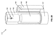
図1及び図2A〜図2Cを参照すると、樽分注装置110の一実施形態が示されており、この実施形態において、分注装置110は好ましくは、ハウジング102の上側カラム108の前面部分101に取り付けられた注ぎ口100を備える。多数の構成及び設計を上側カラム108へと任意選択で組み込むことができるが、図1に最もよく示されているように、上側カラム108は好ましくは、大きい後部及びより小さい前面部分101を備え、それにより、上側カラム108の背面部分は好ましくは、前面部分101よりも大きい直径を備える。注ぎ口100は好ましくは、前面部分101に取り付けられる。従って、この実施形態では、上側扉103が閉じていると、図2A〜図2Cに示されるように、上側カラム108を実質的に均一の外側直径にする。この実施形態では、上側カラム108の前面部分101から注ぎ口100が突き出しているので、上側扉103は好ましくは、それらの内部曲率半径の頂部部分に関して突出部分を備え、それにより、上側扉103が閉じているときに隠れるように、注ぎ口100の周りに内部ボイドが形成される。
With reference to FIGS. 1 and 2A-2C, one embodiment of a
ハウジング102は好ましくは、冷却ユニットハウジング部分107から樽コンパートメント109を通って(図3A、図3B及び図3Cを参照)上側カラム108まで延びる内部ボイドを備え、それにより、樽106から注ぎ口100に至るラインを進む飲料について一貫した温度が維持される。一貫した温度を維持するこの能力により、均一且つ適切に飲料を冷やすことが可能になり、それにより、温度によって誘発される炭酸飲料における泡が回避される。一実施形態では、上側カラム108は、少なくとも約16平方インチの内断面積419(図4Bを参照)を、最も好ましくは少なくとも約24平方インチの断面積を備える。この大きい断面積は、注ぎ口へのその接続においてさえ、チューブの周りの空気流を容易にする。空気流のための大きい開口部はまた、分注装置110に対する保守及び修理のための注ぎ口及びライン接続へのアクセスを簡単にする。樽106から注ぎ口100にドラフトラインを取り付け、これは使用適用例に応じた典型的なサイズ及び長さのものとすることができる。
The
ハウジング102から延びるラインの端部の代わりに、上側カラム108の前面部分101上に直接注ぎ口100を配置することによって、冷却ユニット114から直接冷却及び換気が行われ(図3を参照)、従って、従来の樽分注装置とは異なり、注ぎ口100を最小の閉塞で冷却することを可能にすることによって、温度により誘発される泡が最小限に抑えられる。また、この構成は、注ぎ口100を取り付けるためのハウジング102内に組み込まれる区域を生成することによって、ドラフトに関係する接続及びラインを隠すことを可能にする。
By placing the
一実施形態では、上側カラム108の前面部分101は、ハウジング102の外径よりも小さい約3〜約4インチの正面直径を有する。扉103内に収容可能な前面部分101の直径をより小さくすることによって、注ぎ口100を隠せるだけでなく、ドリップトレイ104もまた、下側扉105の上側部分内に収容することができ、それにより、ドリップトレイ104は、下側扉105が閉じているときには注ぎ口の下にある。ドリップトレイ104は扉105の上側部分内に収納されるので、上側扉103が閉じているときには、注ぎ口100が隠されるだけでなく、ドリップトレイ104も隠される。代替実施形態では、上側扉103を短くすることができ、ドリップトレイは、上側扉と下側扉との間の、分注装置110の前面を包み込むハウジング102の一部分に組み込むことができる。
In one embodiment, the
任意選択で、ドリップトレイ104は、取外し可能なドリップトレイを配設することができる凹部を含むことができる。従って、この取外し可能なドリップトレイは、簡単な洗浄及び排水を可能にする。代替実施形態では、ドリップトレイ104は単純に、滴り落ちる液体を収容する凹部を備えることができる。いずれの実施形態でも、ドリップトレイ104により収集される液体が、収集容器、汚水ドレイン及び/又は加熱蒸発トレイを含むことができる所定の区域に導かれるように、ドリップトレイ104にラインを接続することができる。
Optionally,
任意選択で、扉103は、子供のような許可されていない人々が、その中に収納される飲料を分注しないように補助するロック機構111を含むことができる。また、下側扉105が任意選択でロック機構112を含むことができる。冷却ユニット114(図3を参照)及び冷却ユニットハウジング107は、樽コンパートメント109の下に配設されているとして示されているが、分注装置110内に又はその上のどこに配置してもよく、限定はしないが、圧縮冷媒の断熱冷却、ペルチエ効果に基づく電熱冷却器、蒸発冷却、それらの組み合わせなどを含む、望ましい温度に飲料を冷却することが可能な任意の既知のシステム、装置、機構、方法及び/又はそれらの組み合わせに依拠することができる。代替実施形態では、冷却ユニットハウジング107は任意選択で省略してもよく、その代わりに、ハウジング102の別の部分に冷却ユニットが組み込まれ、これは、特に、サイズが縮小された熱電冷却器に当てはまる。
Optionally, the
一実施形態では、上側カラム108を通して、閉じた扉103と上側カラム108の前面部分101との間の区域に冷えた空気が入ることを可能にする1又は複数の通気孔121(図2Aを参照)を提供することができる。この実施形態では、閉じた扉103と上側カラム108の前面部分101との間の区域に入る境界内に、飲用容器を収納することができる。従って、ユーザは、注ぎ口100からグラスに飲料を分注する前にその中に収納された冷えた飲用容器を得ることができる。任意選択で、1又は複数の通気孔121は、ペルチエ熱電冷却器のような1又は複数の冷却板と置換してもよい。これは、予め冷やしたグラスをユーザに提供するが、所望される場合には、扉が閉じているときに閉じた扉103と上側カラム108の前面部分101との間の区域の境界内に蓄積した冷えた空気が注ぎ口100も冷やし、従って、分注される飲料の熱によって誘発される泡が更に回避される。更に、予め冷やしたグラスもまた、熱によって誘発される泡立ちを低減し、より長い時間にわたってより低い温度で提供される飲料をユーザが維持することを可能にする。任意選択で、ドリップトレイ104の下に、あるいは、ドリップトレイのサイズを減少させ、ドリップトレイの側部に冷却板を配置することによって、冷却板を配設することができ、それにより、閉じた扉103と上側カラム108の前面部分101との間の内部空間を冷やすだけでなく、上側扉103が開いている間にユーザはドリップトレイ上の自分の飲用容器を配置することもでき、それによって、より長い時間期間にわたって飲用容器中に含まれる飲料がより低温に保たれる。また、エネルギー消費量を低減する取組みとして、装置は、蛇口扉が開いているときに、チリングプレートとしても知られている冷却板をターンオンするように構成することができ、それにより、飲料容器のためのコースターを冷やす働きをする。任意選択で、通気孔121は、それらを閉じるように、及び/又は、扉103のうちの1又は複数が開いているときにそこへの空気流が遮断されるように構成することができ、従って、冷却された空気が外側の周囲空気に出されることが防止される。
In one embodiment, one or more vent holes 121 (see FIG. 2A) that allow cold air to enter through the
本発明の一実施形態では、上側扉103が提供されるものであっても、又は提供されないものであっても、好ましくは、上側カラム108よりも更に突き出している分注装置110の下側部分に起因して、棚型形状113(図3Aおよび図3Bを参照)が形成される。一実施形態では、上側カラム108とドリップトレイ104との間に、棚型形状113を任意選択で形成することができる。一実施形態では、上側カラム108の前面部分101は任意選択で、実質的に平坦な形状を備えることができる。
In one embodiment of the present invention, even if the
図3A、図3B及び図3Cは、本発明の一実施形態による分注装置110内の冷えた空気の流れを概略的に示す。本発明の一実施形態で教示されるような上側カラム108の凹型構成は、注ぎ口及びドリップトレイを隠すことができるようにしながら同時に、その下側部分が冷えた空気の流れに対して開いたままであることを可能にする。図3Aに示すように分注装置110の下部に冷却ユニット114及び冷却ユニットハウジング107を配設することにより、樽コンパートメント109を通ることを含めて、ハウジング102全体にわたって冷えた空気の流れが可能になり、それにより、樽だけでなく、注ぎ口と樽とを接続する飲料分配ラインもまた冷やされる。代替的には、図3Bに示すように、冷却ユニット114が代わりに上側カラム108内に配設されたときも望ましい結果が得られる。この構成では、冷えた空気は、冷却ユニット114まで循環して戻る前に、樽コンパートメント109を通って冷却ユニット114を下向きに流れる。それによって、図3Aの分注装置110の下部に示される冷却ユニットハウジングが必要なくなる。
3A, 3B and 3C schematically illustrate the flow of chilled air within the
本発明の一実施形態では、上側扉103が提供されるものであっても、又は提供されないものであっても、好ましくは、上側カラム108よりも更に突き出している分注装置110の下側部分に起因して、棚型形状113(図3Aおよび図3Bを参照)が形成される。一実施形態では、上側カラム108とドリップトレイ104との間に、棚型形状113を任意選択で形成することができる。一実施形態では、上側カラム108の前面部分101は任意選択で、実質的に平坦な形状を備えることができる。
In one embodiment of the present invention, even if the
図3Cは、分注装置内のより高い位置にある蒸発器コイルまで冷媒ライン129が延びることを可能にする上側カラムの拡大を示す一実施形態である。冷媒ライン129は上側カラム内に配置された蒸発器コイル130と連通し、それにより、蛇口/注ぎ口132と連通している分注ライン131の冷却を向上させる。高温の空気は上昇し、ユニット内のより高い位置に蒸発器コイル130を配置すると、分注装置内のより温かい空気が冷却されることがよく知られており、従って、対流プロセスが増大し、場合によっては、ファンの必要性がなくなる。本実施形態の1つの側面は、分注装置内の温度ホットスポットを低減するのを助けることである。
FIG. 3C is an embodiment showing an enlargement of the upper column that allows the
図4Aは、外径が約4インチであり、約1/2インチの断熱材413を有し、従って、空気が流れるために、約3インチ直径の内側開口部414しか残っていない、従来の樽分注カラム412を示している。この小さい内側の空気流直径を、図4Bに示す本発明の分注装置110の一実施形態の同一縮尺の図面と比較する。そこに示されているように、大きいサイズの上側カラム108は、より小径の前面部分101と連携して、従来の樽分注装置において直面するものとほぼ同程度に空気流を制限することなく、より厚い断熱材117(任意選択で、約1インチ厚)の使用を可能する。また、この構成は、簡単に隠すことができるドリップトレイ104を配置するためのシート418を生成する。更に、上側カラム108のより小径の前面部分101により、従来の樽分注装置において直面するように注ぎ口への空気流を大幅に制限することなく、複数の注ぎ口の任意選択の配置が可能になる。従って、1又は複数の注ぎ口を接続するラインの周りにおけるこの増大した冷えた空気の流れは、ラインの端部部分に含まれる飲料の温度を低減し、それにより、ラインの周りに低温の空気を入れるために追加のブロワーを設置する必要なしに、最初に提供された飲料が典型的な分注装置のものよりも低温であることが可能になる。
FIG. 4A is a conventional one having an outer diameter of about 4 inches and having an
図5に示すように、任意選択で、上側扉103によって生成された境界内にハンドルがあることを可能にするために注ぎ口100を回転させることができるように、注ぎ口100は、拡張された長さを有するハンドル119に適応するように回転可能に結合することができる。この実施形態では、注ぎ口100は、約180度以上回転することができる。任意選択で、注ぎ口100を上位置及び/又は下位置にロックするために、解除機構(図示せず)を提供してもよい。解除機構は、任意の既知の機構であり得る。
As shown in FIG. 5, the
次に図6A及び図6Bを参照すると、分注装置の外観が従来の水冷却器に外観を似せているか、あるいは加圧された樽及び/又は加圧可能な樽に含まれる飲料と併せて実際に分注装置に水を分注させる多目的分注装置620及び621が示されている。例示された2つの実施形態では、ドリップトレイ622と、従来の水冷却器の注ぎ口に似ている1又は複数の注ぎ口623とがハウジング扉上に配置され、それらのうちの1又は複数は、僅かに外に突き出し得る。図6Aに示す場合には、所望に応じて、家庭用冷却装置において使用されるものに類似する給水ラインを任意選択で提供し、それを、分注装置620に取り付けられ得るろ過システムに接続することができる。図6Bに示すように、従来の既知の水冷却器システムを含むがこれには限られない分注装置621の上側端部に配設された投入タップに、任意選択で水ボトル624を接続してもよい。これらの実施形態の各々において、任意選択で注ぎ口のうちの一方から水を分注することができ、他方から樽の飲料を分注することができる。任意選択で、分注装置620又は621のいずれかの中に冷却コンパートメントを提供することができ、それにより、冷えた水を分注することができる。注ぎ口623は任意選択で、注ぎ口棚625内に配設される。任意選択で、一実施形態では、分注装置620及び/又は621は任意選択で、1又は複数の上側扉103を含むことができ、上側扉103を開いて、分注装置内に含まれている樽から飲料を分注する注ぎ口を露わにすることができる。この実施形態では、ユーザは任意選択で、開放しており目立つ注ぎ口棚625に複数の水用注ぎ口を有することができ、それにより、分注装置620及び/又は621は、樽分注装置をとして同時に機能しながら、機能及び従来形の水冷却器に似せることができる。任意選択で、注ぎ口が動作しないように、あるいは、注ぎ口のうちの1又は複数が分注装置620及び/又は621内に含まれる樽から飲料を分注するように、注ぎ口棚625の注ぎ口から給水を接続解除することができる。
Referring now to FIGS. 6A and 6B, the dispensing device looks similar to a conventional water cooler, or in conjunction with a beverage contained in a pressurized and / or pressurizable barrel.
次に図7A及び図7Bを参照すると、本発明の更に別の実施形態に従って、抗泡樽分注装置110は、1つの1/2バレル樽あるいは複数のスリム樽106、106’及び106’’を分注するために、増大した直径を備えることができる。この実施形態では、分注装置110の直径が増大すると、上側カラム108の前面部分101のサイズもまた増大し、従って、複数の注ぎ口100、100’及び100’’に適応することが可能になる。更にまた、分注装置110の直径が増大すると、上側カラム108の断面積もまた増大し、それにより、今度は、そこへの冷えた空気の流れの量を同時に増やしながら複数のタップラインに適応することが可能になる。
Referring now to FIGS. 7A and 7B, in accordance with yet another embodiment of the present invention, the
図8Aは、図7A及び図7Bに示された実質的に円形の断面形状ではなく、図8A〜図8Dに示される分注装置110の実施形態は、代わりにより楕円形の断面形状を備えることを除いて、図7A及び図7Bに示したものと同様の分注装置110の一実施形態の正面斜視図を示す。図8Bは、単一の大きい樽800、より小さい2つの樽802、及びより小さい3つの樽804の配置を概略的に示す上面図である。例えば、一実施形態では、分注装置110は、楕円形状を備えることができ、1/2スリム樽、2つの1/2樽、3つの1/6スリム樽に適応することができる。図示のように、楕円形の断面形状は、いくつかの異なる組合せの樽に適応することを依然として可能にし、且つ、審美的に魅力的な外観を依然として維持しながら、分注装置110の占有面積を低減するのを助ける。
FIG. 8A is not the substantially circular cross-sectional shape shown in FIGS. 7A and 7B, but the embodiment of the
次に図9を参照すると、一実施形態では、分注装置110は、脱着可能なハンドル928を有する注ぎ口100を備えることができる。任意選択で、ハンドル928は、クイック接続カプラであり得る凹型カプラ926を備えることができ、注ぎ口100は、同じくクイック接続カプラであり得る凸型カプラ927を備えることができ、あるいはその逆でもよい。この構成により、注ぎ口100へのタップハンドル928の簡単な接続及び接続解除が可能になる。この配列はまた、ハンドル928を取り外した後に上側扉103を閉じることを依然として可能にしながら、前面部分101のより高い位置に注ぎ口100を設置する能力を提供する。これは、より背の高いガラス製品の使用が可能になるので好ましい。代替的には、前面部分101の頂部のより近くに注ぎ口100を配設することにより、上側カラム108を短くすることが可能になり、従って、分注装置110の全高が低減される。更にまた、凸型カプラを覆い、適切な鍵がないと注ぎ口100を動作させることができないように鍵解除機構を有する注ぎ口自体に、ロック機構(図示せず)を直接取り付けることができる。
Referring now to FIG. 9, in one embodiment, dispensing
図11A、図11B及び図11Cは、垂直軸1108を中心にして中央ピボット1101上で枢動することによって上側扉103が開く、本発明の更に別の実施形態を示している。上側扉103は、使用中の分注装置の占有面積を少なくし、扉が開いている間に誰かの衣類又は身体の一部が扉の縁部に引っかかり、従って、人に怪我をさせる又は分注装置自体を損傷させる可能性を減少させるための取り組みとして、上側カラムの周囲で開く。上側扉103の始動及び物理的な開放は、好ましくは、機械、電子、油圧、機構又は任意の他の手段を含む自動アクションによって行われる。記載された全ての手段で十分であるが、直接的な電力又はギヤを介した1又は複数の電気モータ1107が扉の開閉に電力供給することが好適である。また、プロセスの間に何らかが扉の開閉を妨げる又は阻害する場合に扉の開閉を停止又は逆転させるために、何らかのタイプのセンサを所定の位置にセットすることが好ましい。アンペアメータ、磁界センサ及びモーションを含むがこれらには限られない任意のタイプのセンサがよい。
11A, 11B, and 11C illustrate yet another embodiment of the present invention in which the
分注装置ハウジングの上側部分(好ましくは、入口扉1106が分注装置ハウジングの頂部に配置されている)、好ましくは配置されたCO2チャンバは、アクセスを容易にするために、樽106に接続されるCO2供給ライン1105を経由して樽カプラに接続されるCO2タンク又はカートリッジ1102を簡易に設置し、取り外すように設計される。CO2タンクは、わずか数オンスの気体を含有するペイントボールガンで使用されるものから、ポンド単位で測定される標準的な樽を推進するために使用される標準的なサイズのタンク又はシリンダまで、あらゆるタイプに及ぶサイズ及びスタイルでよい。いずれのタンクが使用される場合でも、直立時にタンクの頂部に載置され、タンクのほぼ全長にわたり、底部の近くで終端するタンクコネクタから延びるチューブ1103を装備していることが好適である。チューブ1103の目的は、道具を必要とし、接続時間を無駄にする標準的な方法とは対照的に、タンクを逆さまにし、CO2供給ライン1105にタンクを接続するためにより便利な方法をより簡単に使用することを可能にすることである。CO2タンクと樽カプラとの間のいずれかの場所に、描かれていない圧力調整器が配置される。
An upper portion of the dispenser housing (preferably an
図12A及び図12Bは、分注装置の上側カラム上で垂直断面1203の中心に沿って好ましくは延びる水平軸1204上で枢動することによって、蛇口1202を隠すための蛇口扉1201が開く、本発明の更に別の実施形態を表している。必須ではないが、扉は、1若しくは複数のモータによって、又はそのようなモータの直接駆動によって電力供給されるギヤアセンブリを使用することによって開閉することが好適である。モータが使用されない場合、ギヤは、扉のうちの1つを開いたときに、一斉に扉を開くように作用する。
12A and 12B show a book in which the
図13A及び図13Bは、解除機構1303を押圧するとグライドアセンブリ1302において蛇口1301を上下にスライドさせることが可能であり、押し下げると蛇口1301が定位置にロックされる、本発明のさらに別の実施形態を示している。解除機構及びグライドアセンブリは、任意の利用可能なもので構成され得る。この構成は、分注装置のデザインをよりコンパクトにすること可能にし、同時に、より背の高いガラス製品又はピッチャーの使用を可能にする点で有効である。描かれていないが、上側カラム全体をテレスコープ式に上下させる場合に何らか効果があり、少なくとも、蛇口を上下に動かすことが可能であることと同じ効果を提供する。
FIGS. 13A and 13B show yet another embodiment of the invention in which the
冷却ユニットハウジング107は、好ましくは、コンプレッサ114及び圧縮コイル1107のような分注装置の構成要素のうちのいくつかにアクセスするために、好ましくは分注装置の下部後面に配置されたアクセスパネル1104を含む。フラッシュチラー及びヒータのような他の望ましい構成要素(図示せず)を、蛇口への飲料の流れを阻害又は可能にするバルブと共に、上側チャンバの蛇口の近くに配置することが好適である。炭酸水を作るために必要な構成要素の全ては、本発明の成立時に本発明に既に含まれており、単に、好適な様式でそれらを配列したに過ぎない。
The cooling
迅速にハンドル928を接続及び接続解除する能力があると、ユーザはまた任意選択で、複数の色分けされたカプラ、注ぎ口及び/又はタップハンドルを保有することができ、それにより、詳細には複数の注ぎ口を提供するような実施形態について、適切なタップハンドルを適切な注ぎ口に取り付けることを保証する方法が提供される。
With the ability to quickly connect and disconnect
本発明の更に別の実施形態は、樽内の残っている飲料の温度及び/又は残量を監視する能力をユーザに提供する。1又は複数の温度センサを使用して温度を監視することができ、1又は複数の温度レベルを、任意選択で液晶ディスプレイ、発光ダイオードディスプレイ又は別の電気的ディスプレイ装置を含み得るディスプレイ929(図9を参照)に表示することができる。任意選択で、樽の実際の重量及びその含有量を空の樽の重量と比較する圧力センサにより、樽の残りの容量を判断することができる。樽の流体レベルをディスプレイ929に表示することができる。温度と樽レベルの両方が表示される一実施形態では、任意選択で、ディスプレイ929に両方を表示しても、あるいは別々のディスプレイデバイスに表示してもよい。
Yet another embodiment of the present invention provides the user with the ability to monitor the temperature and / or remaining amount of beverage remaining in the keg. One or more temperature sensors can be used to monitor temperature, and one or more temperature levels can optionally include a liquid crystal display, a light emitting diode display, or another electrical display device (see FIG. 9). Can be displayed. Optionally, the remaining capacity of the barrel can be determined by a pressure sensor that compares the actual weight of the barrel and its content with the weight of the empty barrel. The barrel fluid level can be displayed on the
次に各図を全般的に参照すると、一実施形態では、扉103及び/又は105のうちの1又は複数のためのヒンジは、好ましくは、閉じたときに隠れている。一実施形態では、注ぎ口100は、分注装置分注装置の頂面、又は上側カラム108の頂面には配設されない。一実施形態では、分注装置は、分注装置110内のそれを配置する前に氷又は冷却された別の物質では冷却されないし、それには依拠しない。一実施形態では、上側カラム108は、円筒形でない。一実施形態では、本発明の冷却ユニットは、冷却空気を循環させるためにファンを1つだけ備えており、タップラインを取り囲む区域に冷えた空気を入れるための追加のブロワーを備えていない。一実施形態では、樽106は、任意のすぐに飲める飲料を備えることができる。任意選択で、樽106は、任意のすぐに飲める炭酸飲料を備えることができる。一実施形態では、樽106は、バッグインボックス又はその構成要素を備えない。
Referring now generally to the figures, in one embodiment, the hinges for one or more of the
図10A〜図10Gは、本発明の一実施形態による樽分注装置の装飾用の実施形態の正面斜視図、正面図、背面図、左側面図、右側面図、並びに上面図及び底面図をそれぞれ示している。 10A to 10G are a front perspective view, a front view, a rear view, a left side view, a right side view, and a top view and a bottom view of a decorative embodiment of a barrel dispensing device according to an embodiment of the present invention. Each is shown.
本発明について、これらの好適な実施形態を特に参照しながら詳細に記載してきたが、他の実施形態により同じ結果を達成することができる。本発明の変形形態及び修正形態が当業者には明らかであろう、また、添付の特許請求の範囲において、全てのそのような修正形態及び等価形態を網羅することが意図される。上記で参照した及び/又は添付の全ての引例、出願、特許及び公報、並びに対応する(1又は複数の)出願の開示全体は、参照により本明細書に組み込まれる。 Although the invention has been described in detail with particular reference to these preferred embodiments, other embodiments can achieve the same results. Variations and modifications of the present invention will be apparent to those skilled in the art, and it is intended that the appended claims cover all such modifications and equivalents. The entire disclosure of all references, applications, patents and publications referred to above and / or attached, and the corresponding application (s) are hereby incorporated by reference.
Claims (9)
注ぎ口;及び
樽コンパートメントを含む円筒形状の下側カラム;
を備える飲料分注装置であって、
前記上側カラムが、前記上側カラムの周りに2つの曲線状の扉及びCO 2 タンクを前記分注装置内に配置するための開口部を備え、前記2つの曲線状の扉が、前記分注装置の垂直軸に配置された枢軸中心で、前記上側カラムの周りを枢動し、
前記2つの曲線状の扉が前記開口部の上に位置した場合に、前記開口部は隠れ、
前記上側カラムは前記下側カラム上に載置され、前記上側カラムの円周は、前記下側カラムの円周より小さく、前記2つの曲線状の扉は、前記下側カラムの円周において、前記上側カラムの外側の周りを枢動し、
前記注ぎ口が、前記上側カラムの周りの前記2つの曲線状の扉を閉じたときに隠れ、
前記垂直軸が前記分注装置の中心にある、飲料分注装置。 Cylindrical upper column;
A spout; and a cylindrical lower column containing a barrel compartment;
A beverage dispensing device comprising:
The upper column, with an opening for placement in the dispensing device with two curved doors and CO 2 tank around the upper column, the two curved doors, the fraction Pivot about the upper column at the pivot center located on the vertical axis of the pouring device;
When the two curvilinear doors are located on the opening, the opening is hidden,
The upper column is placed on the lower column, the circumference of the upper column is smaller than the circumference of the lower column, and the two curved doors are located at the circumference of the lower column, Pivot around the outside of the upper column,
Hidden when the spout closes the two curvilinear doors around the upper column;
Beverage dispensing device, wherein the vertical axis is at the center of the dispensing device.
Applications Claiming Priority (5)
| Application Number | Priority Date | Filing Date | Title |
|---|---|---|---|
| US201361961789P | 2013-10-24 | 2013-10-24 | |
| US61/961,789 | 2013-10-24 | ||
| US201461964852P | 2014-01-16 | 2014-01-16 | |
| US61/964,852 | 2014-01-16 | ||
| PCT/US2014/061963 WO2015061564A1 (en) | 2013-10-24 | 2014-10-23 | Versatile and aesthetically refined keg dispenser |
Publications (3)
| Publication Number | Publication Date |
|---|---|
| JP2016536234A JP2016536234A (en) | 2016-11-24 |
| JP2016536234A5 JP2016536234A5 (en) | 2017-11-24 |
| JP6494644B2 true JP6494644B2 (en) | 2019-04-03 |
Family
ID=52993557
Family Applications (1)
| Application Number | Title | Priority Date | Filing Date |
|---|---|---|---|
| JP2016550667A Active JP6494644B2 (en) | 2013-10-24 | 2014-10-23 | Multipurpose and aesthetically improved barrel dispensing device |
Country Status (10)
| Country | Link |
|---|---|
| US (1) | US10301165B2 (en) |
| EP (1) | EP3060514A4 (en) |
| JP (1) | JP6494644B2 (en) |
| KR (1) | KR102357243B1 (en) |
| CN (2) | CN106103335A (en) |
| AU (1) | AU2014340059B2 (en) |
| BR (1) | BR112016009215B1 (en) |
| CA (1) | CA2965475C (en) |
| MX (1) | MX2016005320A (en) |
| WO (1) | WO2015061564A1 (en) |
Families Citing this family (13)
| Publication number | Priority date | Publication date | Assignee | Title |
|---|---|---|---|---|
| US20120132673A1 (en) | 2010-02-12 | 2012-05-31 | Robert Leyva | Foam Resistant Keg Dispenser |
| US9114368B2 (en) | 2013-03-08 | 2015-08-25 | Cornelius, Inc. | Batch carbonator and method of forming a carbonated beverage |
| MX2016005320A (en) | 2013-10-24 | 2017-02-15 | LEYVA Robert | Versatile and aesthetically refined keg dispenser. |
| US11124406B1 (en) * | 2014-07-13 | 2021-09-21 | Sestra Systems, Inc. | System and method for piston detection in a metering mechanism for use with beverage dispensing system |
| US10196254B2 (en) * | 2015-01-28 | 2019-02-05 | Pik Six LLC | Compact portable cooling container and keg dispenser |
| US10477883B2 (en) | 2015-08-25 | 2019-11-19 | Cornelius, Inc. | Gas injection assemblies for batch beverages having spargers |
| US10785996B2 (en) | 2015-08-25 | 2020-09-29 | Cornelius, Inc. | Apparatuses, systems, and methods for inline injection of gases into liquids |
| US10017373B2 (en) | 2016-04-15 | 2018-07-10 | Automatic Bar Controls, Inc. | Nitrogen generator and uses thereof |
| KR200484718Y1 (en) * | 2017-02-16 | 2017-10-18 | 오비맥주 주식회사 | All-in-one type cooling device for draft beer |
| US11034569B2 (en) | 2018-02-14 | 2021-06-15 | Taphandles Llc | Cooled beverage dispensing systems and associated devices |
| JP7177430B2 (en) * | 2018-06-11 | 2022-11-24 | 株式会社コスモライフ | water server |
| US11040314B2 (en) | 2019-01-08 | 2021-06-22 | Marmon Foodservice Technologies, Inc. | Apparatuses, systems, and methods for injecting gasses into beverages |
| CN110510563A (en) * | 2019-09-20 | 2019-11-29 | 宁波精酿谷科技有限公司 | A kind of barreled beer on draft wine selling machine |
Family Cites Families (92)
| Publication number | Priority date | Publication date | Assignee | Title |
|---|---|---|---|---|
| US242254A (en) * | 1881-05-31 | peters | ||
| US1080478A (en) * | 1913-01-23 | 1913-12-02 | Theodore Reis | Hood for dispensing-tanks. |
| US2063507A (en) * | 1933-06-03 | 1936-12-08 | Karper Abraham Singer | Waste receptacle |
| US2063171A (en) * | 1934-08-22 | 1936-12-08 | Gen Motors Corp | Refrigerating apparatus |
| US2080786A (en) * | 1935-02-11 | 1937-05-18 | Jose A Robles | Receptacle cover |
| US2109718A (en) * | 1936-07-06 | 1938-03-01 | George W Bayers | Air pump |
| US2223152A (en) | 1940-01-08 | 1940-11-26 | Nagin Max | Beer cooling device |
| US2414929A (en) * | 1943-12-14 | 1947-01-28 | Gen Electric | Combined closure and rack for refrigerators |
| US2596316A (en) * | 1945-12-19 | 1952-05-13 | White Cabinet Corp | Refrigerator |
| US2744672A (en) * | 1949-11-10 | 1956-05-08 | Crist Buckley | Beverage dispensing machine |
| US2774229A (en) * | 1955-07-25 | 1956-12-18 | Kay Tee Corp | Draft beer dispenser |
| US2792692A (en) * | 1955-09-21 | 1957-05-21 | Reed A Bryan | Keg cooler and dispensing bar unit |
| US3482801A (en) * | 1968-04-04 | 1969-12-09 | Diebold Inc | Closure for pneumatic system carrier |
| US3599371A (en) * | 1969-07-03 | 1971-08-17 | Louis F Barroero | Door opening and closing means |
| US3712514A (en) * | 1971-03-29 | 1973-01-23 | R Leblanc | Portable beer dispenser |
| US3885711A (en) * | 1972-04-17 | 1975-05-27 | Charles P Martindale | Sanitary liquid dispenser |
| US3865276A (en) | 1973-11-26 | 1975-02-11 | Hank A Thompson | Portable keg tapper |
| US3979024A (en) * | 1974-12-27 | 1976-09-07 | The Vendo Company | Ingredient temperature stabilization apparatus for post-mix beverage dispensing machines |
| US4225059A (en) | 1978-12-14 | 1980-09-30 | Christopher Kappos | Portable beverage cooler and dispenser |
| US4350267A (en) * | 1979-12-26 | 1982-09-21 | Nelson Richard E | Portable modular beverage dispenser |
| USD271877S (en) | 1981-06-29 | 1983-12-20 | Hoff Harvey B | Refrigerator with beverage dispenser |
| JPS5884031A (en) * | 1981-11-12 | 1983-05-20 | ザ・コカ−コ−ラ・カンパニ− | Portable post-mixed soft drink supply apparatus |
| USD285052S (en) | 1984-03-27 | 1986-08-12 | Bianchi Walter G | Bottle |
| JPS61130151A (en) | 1984-11-30 | 1986-06-18 | Yokohama Rubber Co Ltd:The | Method and device of automatically winding-in coat material in coat calendar |
| JPS61130151U (en) * | 1985-02-01 | 1986-08-14 | ||
| USD300106S (en) | 1986-01-31 | 1989-03-07 | Calor S.A. | Electric coffee pot |
| USD298602S (en) | 1986-02-14 | 1988-11-22 | Price Sterling A | Combined beverage cooler and dispenser |
| USD311298S (en) | 1986-11-10 | 1990-10-16 | Mollenhoff David V | Hot beverage maker |
| US4690300A (en) * | 1986-12-31 | 1987-09-01 | Woods David E | Insulated cooler for beverage containers |
| JPS6442298A (en) | 1987-08-08 | 1989-02-14 | Fujitsu Ltd | Ruled line ruler for electronic blackboard |
| JPS6442298U (en) * | 1987-09-09 | 1989-03-14 | ||
| US4901887A (en) | 1988-08-08 | 1990-02-20 | Burton John W | Beverage dispensing system |
| DE9006681U1 (en) | 1990-06-13 | 1990-08-23 | Weissbart, Edmund, 8037 Olching, De | |
| US5312017A (en) * | 1991-08-30 | 1994-05-17 | The Coca-Cola Company | Product identification system for beverage dispenser |
| USD352296S (en) | 1992-04-13 | 1994-11-08 | Neal Westendorf | Keg refrigerator |
| JPH0654597U (en) * | 1992-07-21 | 1994-07-26 | 株式会社大橋冷機 | Beverage supply device |
| JPH0654597A (en) | 1992-07-30 | 1994-02-25 | Nec Corp | Stepping motor controller |
| US5318197A (en) * | 1992-10-22 | 1994-06-07 | Automatic Bar Controls | Method and apparatus for control and monitoring of beverage dispensing |
| USD367864S (en) * | 1994-09-06 | 1996-03-12 | Master-Bilt Products | Refrigerated display case |
| US5941103A (en) | 1994-12-21 | 1999-08-24 | Stearns; Kenneth E. | Faucet locking device |
| US5537825A (en) | 1994-12-27 | 1996-07-23 | Ward; Justin | Draft beer tower cooling system |
| USD368271S (en) * | 1995-04-25 | 1996-03-26 | Montgomery Matthew C | Cylindrical combined refrigerator and freezer |
| CN2242222Y (en) * | 1995-08-12 | 1996-12-11 | 吴正伟 | Miniature appliance for applying carbon dioxide |
| US5992684A (en) * | 1996-01-26 | 1999-11-30 | Russell; Larry L. | Water dispensing device |
| JP3037947U (en) * | 1996-04-09 | 1997-06-06 | 清 深町 | Electric operated refrigerator |
| USD399088S (en) | 1997-01-31 | 1998-10-06 | Ebco Manufacturing Corporation | Bottled water cooler |
| US6454131B1 (en) * | 1998-08-31 | 2002-09-24 | Heineken Technical Services B.V. | Beverage dispensing apparatus |
| USD415023S (en) | 1998-03-23 | 1999-10-12 | W. Braun Company | Triangular tri-pack container |
| US6237345B1 (en) | 1998-04-17 | 2001-05-29 | Home Pure L.L.C. | Water cooler and dispenser |
| USD423862S (en) | 1998-10-28 | 2000-05-02 | Oxygen8, Inc. | Water cooler |
| US6502415B2 (en) | 2000-01-20 | 2003-01-07 | Icefloe Technologies Inc. | Beverage cooler |
| DE10011826A1 (en) * | 2000-03-10 | 2001-09-20 | Loh Kg Hailo Werk | Waste collector |
| USD469787S1 (en) | 2002-01-10 | 2003-02-04 | Neil G. Wicker | Beer keg cooler |
| USD489214S1 (en) | 2002-02-15 | 2004-05-04 | Sanyo Electric Co., Ltd. | Coffee maker |
| USD482227S1 (en) | 2002-10-09 | 2003-11-18 | Ebac Limited | Beverage dispenser |
| US6783034B1 (en) | 2002-10-29 | 2004-08-31 | Timothy Brent | Liquid carrier article |
| US7752876B2 (en) * | 2003-01-14 | 2010-07-13 | Master Lock Company Llc | Lockout device |
| US7131560B2 (en) * | 2004-07-15 | 2006-11-07 | Jerry Graham Hammond | Portable beer keg tap and dispenser |
| USD547650S1 (en) | 2004-10-13 | 2007-07-31 | Jamie Limber | Storage container |
| US7150163B1 (en) * | 2004-12-13 | 2006-12-19 | Mcallister Andrea H | Water cooler enclosure |
| US7225951B2 (en) * | 2004-12-15 | 2007-06-05 | Wempe Patrick L | Portable fluid delivery system |
| US7237390B1 (en) | 2005-04-21 | 2007-07-03 | Lance Nelson | Compact portable beverage cooling system |
| US7757908B1 (en) * | 2005-06-13 | 2010-07-20 | Buhl Jr Thomas R | Portable container and dispenser for kegged beer |
| US7343757B2 (en) | 2005-08-11 | 2008-03-18 | Whirlpool Corporation | Integrated center rail dispenser |
| USD555967S1 (en) | 2005-08-12 | 2007-11-27 | Carlsberg Breweries A/S | Draught system |
| DE102007005037A1 (en) * | 2007-02-01 | 2008-08-14 | BSH Bosch und Siemens Hausgeräte GmbH | Dispensing device for tapping of carbon dioxide supply in barrel-like drinks container i.e. party barrel, has locking device for fixing container opposite to tapping device in tapping direction, and activation unit activating tapping device |
| US7975879B2 (en) * | 2007-05-10 | 2011-07-12 | Groesbeck R Clay | Temperature controlled liquid dispenser, containers therefore, and bag-in-box container construction |
| NL1033916C2 (en) * | 2007-05-31 | 2008-12-02 | Heineken Supply Chain Bv | Tapping device, connecting device for a beverage container and cooling device for such a connecting device. |
| NL1033914C2 (en) * | 2007-05-31 | 2008-12-02 | Heineken Supply Chain Bv | Beverage container with coolants. |
| GB2452919B (en) * | 2007-09-18 | 2013-02-13 | Scottish & Newcastle Plc | Systems and methods for dispensing beverage |
| US8217613B2 (en) * | 2008-03-26 | 2012-07-10 | Lg Electronics Inc. | System and method for driving a drawer of a refrigerator and refrigerator employing same |
| USD588852S1 (en) | 2008-05-13 | 2009-03-24 | Beertubes.Com Llc | Can themed beverage dispenser |
| US8231036B2 (en) * | 2008-09-15 | 2012-07-31 | Scott Gerald Campbell | Portable recreation system for motorized vehicles |
| USD640569S1 (en) | 2008-11-20 | 2011-06-28 | Avon Products, Inc | Container |
| JP5878467B2 (en) * | 2009-07-23 | 2016-03-08 | スマート バー インターナショナル エルエルシー | Automatic beverage dispenser |
| USD617603S1 (en) | 2009-10-05 | 2010-06-15 | Hamilton Beach Brands, Inc. | Coffee grinder with integrally stored brush |
| GB2475291B (en) * | 2009-11-12 | 2012-03-28 | Kraft Foods R & D Inc | Beverage preparation machines |
| US20110168775A1 (en) * | 2010-01-13 | 2011-07-14 | Van Zetten Jason D | Automated beverage dispensing system |
| US20120132673A1 (en) | 2010-02-12 | 2012-05-31 | Robert Leyva | Foam Resistant Keg Dispenser |
| USD646104S1 (en) | 2010-05-22 | 2011-10-04 | Midea Group Co., Ltd. | Integral heat pump and hot water dispenser |
| US8496308B2 (en) * | 2011-02-16 | 2013-07-30 | Joseph ZABBATINO | Individual locker assembly for refrigerators |
| USD668903S1 (en) | 2011-06-22 | 2012-10-16 | Cardomon International Limited | Water cooler |
| WO2013105962A1 (en) * | 2012-01-12 | 2013-07-18 | Robert Leyva | Foam resistant keg dispenser |
| USD691643S1 (en) | 2012-06-25 | 2013-10-15 | Brian Sharkey | Refrigerator |
| USD697748S1 (en) | 2012-08-16 | 2014-01-21 | Mtn Products, Inc. | Water cooler |
| US9199833B2 (en) * | 2012-10-22 | 2015-12-01 | Mistee Scarvelli | Self service controlled beverage dispensing system |
| US9073741B2 (en) * | 2012-11-30 | 2015-07-07 | Igusa Llc | Beverage dispensing system |
| USD736024S1 (en) | 2013-10-03 | 2015-08-11 | Flo Water Inc. | Flow device |
| MX2016005320A (en) | 2013-10-24 | 2017-02-15 | LEYVA Robert | Versatile and aesthetically refined keg dispenser. |
| USD735514S1 (en) | 2014-02-10 | 2015-08-04 | Takeya Usa Corporation | Portable brewing device |
| USD734086S1 (en) | 2014-05-30 | 2015-07-14 | Pegatron Corporation | Beverage machine |
| US9809238B2 (en) * | 2015-01-28 | 2017-11-07 | Pik Six LLC | Compact portable cooling container and keg dispenser |
-
2014
- 2014-10-23 MX MX2016005320A patent/MX2016005320A/en active IP Right Grant
- 2014-10-23 CA CA2965475A patent/CA2965475C/en active Active
- 2014-10-23 WO PCT/US2014/061963 patent/WO2015061564A1/en active Application Filing
- 2014-10-23 JP JP2016550667A patent/JP6494644B2/en active Active
- 2014-10-23 AU AU2014340059A patent/AU2014340059B2/en active Active
- 2014-10-23 BR BR112016009215-5A patent/BR112016009215B1/en active IP Right Grant
- 2014-10-23 CN CN201480071146.3A patent/CN106103335A/en active Pending
- 2014-10-23 KR KR1020167013800A patent/KR102357243B1/en active IP Right Grant
- 2014-10-23 EP EP14855031.2A patent/EP3060514A4/en active Pending
- 2014-10-23 CN CN201910932128.4A patent/CN110877887B/en active Active
-
2016
- 2016-04-22 US US15/136,373 patent/US10301165B2/en active Active
Also Published As
| Publication number | Publication date |
|---|---|
| AU2014340059A1 (en) | 2016-06-09 |
| KR102357243B1 (en) | 2022-01-28 |
| EP3060514A1 (en) | 2016-08-31 |
| KR20160106555A (en) | 2016-09-12 |
| CN106103335A (en) | 2016-11-09 |
| CN110877887B (en) | 2021-09-14 |
| CA2965475A1 (en) | 2015-04-30 |
| BR112016009215A8 (en) | 2020-03-24 |
| CA2965475C (en) | 2022-12-13 |
| BR112016009215B1 (en) | 2022-08-16 |
| MX2016005320A (en) | 2017-02-15 |
| EP3060514A4 (en) | 2017-08-02 |
| AU2014340059B2 (en) | 2018-08-23 |
| WO2015061564A1 (en) | 2015-04-30 |
| US20160236926A1 (en) | 2016-08-18 |
| CN110877887A (en) | 2020-03-13 |
| US10301165B2 (en) | 2019-05-28 |
| JP2016536234A (en) | 2016-11-24 |
Similar Documents
| Publication | Publication Date | Title |
|---|---|---|
| JP6494644B2 (en) | Multipurpose and aesthetically improved barrel dispensing device | |
| US20120132673A1 (en) | Foam Resistant Keg Dispenser | |
| AU2003302628B2 (en) | Cooling system for a beverage dispensing apparatus | |
| US5269156A (en) | Method and apparatus for back bar freezer unit | |
| CA2141501C (en) | Beverage dispenser | |
| US20160347598A1 (en) | Beverage cooler | |
| US6230513B1 (en) | Water cooler and dispenser | |
| US20110006078A1 (en) | Beverage device and tank thereof | |
| US11326825B2 (en) | Stand-alone ice and beverage appliance | |
| US20180135911A1 (en) | Rapid Cooling Apparatus | |
| WO2013105962A1 (en) | Foam resistant keg dispenser | |
| AU2019418308B2 (en) | Method and apparatus for dispensing a beverage in chilled condition | |
| AU2018100137A4 (en) | Refrigerated Self-Contained Pressurised Tank for Dispensing Gas Infused Cold Beverages | |
| KR100555216B1 (en) | draught beer selling apparatus | |
| US20070138205A1 (en) | On demand drink dispenser | |
| US11680734B2 (en) | Portable insulated thermo-electric cooler and dispenser | |
| KR102344165B1 (en) | Draft beer refrigerator storage device | |
| KR100629953B1 (en) | Hot and Chilled Water Generator | |
| EP2042823A1 (en) | Home refrigerator with a cooled-drink dispenser | |
| JP2000234837A (en) | Raw beer cooling/extraction apparatus |
Legal Events
| Date | Code | Title | Description |
|---|---|---|---|
| A521 | Request for written amendment filed |
Free format text: JAPANESE INTERMEDIATE CODE: A523 Effective date: 20171012 |
|
| A621 | Written request for application examination |
Free format text: JAPANESE INTERMEDIATE CODE: A621 Effective date: 20171012 |
|
| A977 | Report on retrieval |
Free format text: JAPANESE INTERMEDIATE CODE: A971007 Effective date: 20180713 |
|
| A131 | Notification of reasons for refusal |
Free format text: JAPANESE INTERMEDIATE CODE: A131 Effective date: 20180731 |
|
| A521 | Request for written amendment filed |
Free format text: JAPANESE INTERMEDIATE CODE: A523 Effective date: 20181031 |
|
| TRDD | Decision of grant or rejection written | ||
| A01 | Written decision to grant a patent or to grant a registration (utility model) |
Free format text: JAPANESE INTERMEDIATE CODE: A01 Effective date: 20190205 |
|
| A61 | First payment of annual fees (during grant procedure) |
Free format text: JAPANESE INTERMEDIATE CODE: A61 Effective date: 20190305 |
|
| R150 | Certificate of patent or registration of utility model |
Ref document number: 6494644 Country of ref document: JP Free format text: JAPANESE INTERMEDIATE CODE: R150 |
|
| S111 | Request for change of ownership or part of ownership |
Free format text: JAPANESE INTERMEDIATE CODE: R313113 |
|
| R350 | Written notification of registration of transfer |
Free format text: JAPANESE INTERMEDIATE CODE: R350 |
|
| R250 | Receipt of annual fees |
Free format text: JAPANESE INTERMEDIATE CODE: R250 |
|
| R250 | Receipt of annual fees |
Free format text: JAPANESE INTERMEDIATE CODE: R250 |
|
| R250 | Receipt of annual fees |
Free format text: JAPANESE INTERMEDIATE CODE: R250 |