JP6492921B2 - Tractor - Google Patents
Tractor Download PDFInfo
- Publication number
- JP6492921B2 JP6492921B2 JP2015086254A JP2015086254A JP6492921B2 JP 6492921 B2 JP6492921 B2 JP 6492921B2 JP 2015086254 A JP2015086254 A JP 2015086254A JP 2015086254 A JP2015086254 A JP 2015086254A JP 6492921 B2 JP6492921 B2 JP 6492921B2
- Authority
- JP
- Japan
- Prior art keywords
- exhaust gas
- gas treatment
- urea water
- treatment unit
- support member
- Prior art date
- Legal status (The legal status is an assumption and is not a legal conclusion. Google has not performed a legal analysis and makes no representation as to the accuracy of the status listed.)
- Active
Links
Images


Classifications
-
- B—PERFORMING OPERATIONS; TRANSPORTING
- B01—PHYSICAL OR CHEMICAL PROCESSES OR APPARATUS IN GENERAL
- B01D—SEPARATION
- B01D53/00—Separation of gases or vapours; Recovering vapours of volatile solvents from gases; Chemical or biological purification of waste gases, e.g. engine exhaust gases, smoke, fumes, flue gases, aerosols
- B01D53/34—Chemical or biological purification of waste gases
- B01D53/92—Chemical or biological purification of waste gases of engine exhaust gases
- B01D53/94—Chemical or biological purification of waste gases of engine exhaust gases by catalytic processes
- B01D53/9404—Removing only nitrogen compounds
- B01D53/9409—Nitrogen oxides
- B01D53/9431—Processes characterised by a specific device
-
- B—PERFORMING OPERATIONS; TRANSPORTING
- B60—VEHICLES IN GENERAL
- B60K—ARRANGEMENT OR MOUNTING OF PROPULSION UNITS OR OF TRANSMISSIONS IN VEHICLES; ARRANGEMENT OR MOUNTING OF PLURAL DIVERSE PRIME-MOVERS IN VEHICLES; AUXILIARY DRIVES FOR VEHICLES; INSTRUMENTATION OR DASHBOARDS FOR VEHICLES; ARRANGEMENTS IN CONNECTION WITH COOLING, AIR INTAKE, GAS EXHAUST OR FUEL SUPPLY OF PROPULSION UNITS IN VEHICLES
- B60K13/00—Arrangement in connection with combustion air intake or gas exhaust of propulsion units
- B60K13/04—Arrangement in connection with combustion air intake or gas exhaust of propulsion units concerning exhaust
-
- B—PERFORMING OPERATIONS; TRANSPORTING
- B60—VEHICLES IN GENERAL
- B60K—ARRANGEMENT OR MOUNTING OF PROPULSION UNITS OR OF TRANSMISSIONS IN VEHICLES; ARRANGEMENT OR MOUNTING OF PLURAL DIVERSE PRIME-MOVERS IN VEHICLES; AUXILIARY DRIVES FOR VEHICLES; INSTRUMENTATION OR DASHBOARDS FOR VEHICLES; ARRANGEMENTS IN CONNECTION WITH COOLING, AIR INTAKE, GAS EXHAUST OR FUEL SUPPLY OF PROPULSION UNITS IN VEHICLES
- B60K15/00—Arrangement in connection with fuel supply of combustion engines or other fuel consuming energy converters, e.g. fuel cells; Mounting or construction of fuel tanks
- B60K15/03—Fuel tanks
-
- F—MECHANICAL ENGINEERING; LIGHTING; HEATING; WEAPONS; BLASTING
- F01—MACHINES OR ENGINES IN GENERAL; ENGINE PLANTS IN GENERAL; STEAM ENGINES
- F01N—GAS-FLOW SILENCERS OR EXHAUST APPARATUS FOR MACHINES OR ENGINES IN GENERAL; GAS-FLOW SILENCERS OR EXHAUST APPARATUS FOR INTERNAL COMBUSTION ENGINES
- F01N3/00—Exhaust or silencing apparatus having means for purifying, rendering innocuous, or otherwise treating exhaust
- F01N3/08—Exhaust or silencing apparatus having means for purifying, rendering innocuous, or otherwise treating exhaust for rendering innocuous
- F01N3/10—Exhaust or silencing apparatus having means for purifying, rendering innocuous, or otherwise treating exhaust for rendering innocuous by thermal or catalytic conversion of noxious components of exhaust
- F01N3/105—General auxiliary catalysts, e.g. upstream or downstream of the main catalyst
- F01N3/106—Auxiliary oxidation catalysts
-
- F—MECHANICAL ENGINEERING; LIGHTING; HEATING; WEAPONS; BLASTING
- F01—MACHINES OR ENGINES IN GENERAL; ENGINE PLANTS IN GENERAL; STEAM ENGINES
- F01N—GAS-FLOW SILENCERS OR EXHAUST APPARATUS FOR MACHINES OR ENGINES IN GENERAL; GAS-FLOW SILENCERS OR EXHAUST APPARATUS FOR INTERNAL COMBUSTION ENGINES
- F01N3/00—Exhaust or silencing apparatus having means for purifying, rendering innocuous, or otherwise treating exhaust
- F01N3/08—Exhaust or silencing apparatus having means for purifying, rendering innocuous, or otherwise treating exhaust for rendering innocuous
- F01N3/10—Exhaust or silencing apparatus having means for purifying, rendering innocuous, or otherwise treating exhaust for rendering innocuous by thermal or catalytic conversion of noxious components of exhaust
- F01N3/18—Exhaust or silencing apparatus having means for purifying, rendering innocuous, or otherwise treating exhaust for rendering innocuous by thermal or catalytic conversion of noxious components of exhaust characterised by methods of operation; Control
- F01N3/20—Exhaust or silencing apparatus having means for purifying, rendering innocuous, or otherwise treating exhaust for rendering innocuous by thermal or catalytic conversion of noxious components of exhaust characterised by methods of operation; Control specially adapted for catalytic conversion ; Methods of operation or control of catalytic converters
- F01N3/2066—Selective catalytic reduction [SCR]
- F01N3/2073—Selective catalytic reduction [SCR] with means for generating a reducing substance from the exhaust gases
-
- B—PERFORMING OPERATIONS; TRANSPORTING
- B01—PHYSICAL OR CHEMICAL PROCESSES OR APPARATUS IN GENERAL
- B01D—SEPARATION
- B01D2251/00—Reactants
- B01D2251/20—Reductants
- B01D2251/206—Ammonium compounds
- B01D2251/2067—Urea
-
- B—PERFORMING OPERATIONS; TRANSPORTING
- B60—VEHICLES IN GENERAL
- B60Y—INDEXING SCHEME RELATING TO ASPECTS CROSS-CUTTING VEHICLE TECHNOLOGY
- B60Y2200/00—Type of vehicle
- B60Y2200/20—Off-Road Vehicles
- B60Y2200/22—Agricultural vehicles
- B60Y2200/221—Tractors
-
- F—MECHANICAL ENGINEERING; LIGHTING; HEATING; WEAPONS; BLASTING
- F01—MACHINES OR ENGINES IN GENERAL; ENGINE PLANTS IN GENERAL; STEAM ENGINES
- F01N—GAS-FLOW SILENCERS OR EXHAUST APPARATUS FOR MACHINES OR ENGINES IN GENERAL; GAS-FLOW SILENCERS OR EXHAUST APPARATUS FOR INTERNAL COMBUSTION ENGINES
- F01N13/00—Exhaust or silencing apparatus characterised by constructional features ; Exhaust or silencing apparatus, or parts thereof, having pertinent characteristics not provided for in, or of interest apart from, groups F01N1/00 - F01N5/00, F01N9/00, F01N11/00
- F01N13/009—Exhaust or silencing apparatus characterised by constructional features ; Exhaust or silencing apparatus, or parts thereof, having pertinent characteristics not provided for in, or of interest apart from, groups F01N1/00 - F01N5/00, F01N9/00, F01N11/00 having two or more separate purifying devices arranged in series
-
- F—MECHANICAL ENGINEERING; LIGHTING; HEATING; WEAPONS; BLASTING
- F01—MACHINES OR ENGINES IN GENERAL; ENGINE PLANTS IN GENERAL; STEAM ENGINES
- F01N—GAS-FLOW SILENCERS OR EXHAUST APPARATUS FOR MACHINES OR ENGINES IN GENERAL; GAS-FLOW SILENCERS OR EXHAUST APPARATUS FOR INTERNAL COMBUSTION ENGINES
- F01N13/00—Exhaust or silencing apparatus characterised by constructional features ; Exhaust or silencing apparatus, or parts thereof, having pertinent characteristics not provided for in, or of interest apart from, groups F01N1/00 - F01N5/00, F01N9/00, F01N11/00
- F01N13/08—Other arrangements or adaptations of exhaust conduits
-
- F—MECHANICAL ENGINEERING; LIGHTING; HEATING; WEAPONS; BLASTING
- F01—MACHINES OR ENGINES IN GENERAL; ENGINE PLANTS IN GENERAL; STEAM ENGINES
- F01N—GAS-FLOW SILENCERS OR EXHAUST APPARATUS FOR MACHINES OR ENGINES IN GENERAL; GAS-FLOW SILENCERS OR EXHAUST APPARATUS FOR INTERNAL COMBUSTION ENGINES
- F01N2340/00—Dimensional characteristics of the exhaust system, e.g. length, diameter or volume of the apparatus; Spatial arrangements of exhaust apparatuses
- F01N2340/04—Dimensional characteristics of the exhaust system, e.g. length, diameter or volume of the apparatus; Spatial arrangements of exhaust apparatuses characterised by the arrangement of an exhaust pipe, manifold or apparatus in relation to vehicle frame or particular vehicle parts
-
- F—MECHANICAL ENGINEERING; LIGHTING; HEATING; WEAPONS; BLASTING
- F01—MACHINES OR ENGINES IN GENERAL; ENGINE PLANTS IN GENERAL; STEAM ENGINES
- F01N—GAS-FLOW SILENCERS OR EXHAUST APPARATUS FOR MACHINES OR ENGINES IN GENERAL; GAS-FLOW SILENCERS OR EXHAUST APPARATUS FOR INTERNAL COMBUSTION ENGINES
- F01N2590/00—Exhaust or silencing apparatus adapted to particular use, e.g. for military applications, airplanes, submarines
- F01N2590/08—Exhaust or silencing apparatus adapted to particular use, e.g. for military applications, airplanes, submarines for heavy duty applications, e.g. trucks, buses, tractors, locomotives
-
- F—MECHANICAL ENGINEERING; LIGHTING; HEATING; WEAPONS; BLASTING
- F01—MACHINES OR ENGINES IN GENERAL; ENGINE PLANTS IN GENERAL; STEAM ENGINES
- F01N—GAS-FLOW SILENCERS OR EXHAUST APPARATUS FOR MACHINES OR ENGINES IN GENERAL; GAS-FLOW SILENCERS OR EXHAUST APPARATUS FOR INTERNAL COMBUSTION ENGINES
- F01N2610/00—Adding substances to exhaust gases
- F01N2610/02—Adding substances to exhaust gases the substance being ammonia or urea
-
- F—MECHANICAL ENGINEERING; LIGHTING; HEATING; WEAPONS; BLASTING
- F01—MACHINES OR ENGINES IN GENERAL; ENGINE PLANTS IN GENERAL; STEAM ENGINES
- F01N—GAS-FLOW SILENCERS OR EXHAUST APPARATUS FOR MACHINES OR ENGINES IN GENERAL; GAS-FLOW SILENCERS OR EXHAUST APPARATUS FOR INTERNAL COMBUSTION ENGINES
- F01N2610/00—Adding substances to exhaust gases
- F01N2610/14—Arrangements for the supply of substances, e.g. conduits
- F01N2610/1406—Storage means for substances, e.g. tanks or reservoirs
-
- F—MECHANICAL ENGINEERING; LIGHTING; HEATING; WEAPONS; BLASTING
- F01—MACHINES OR ENGINES IN GENERAL; ENGINE PLANTS IN GENERAL; STEAM ENGINES
- F01N—GAS-FLOW SILENCERS OR EXHAUST APPARATUS FOR MACHINES OR ENGINES IN GENERAL; GAS-FLOW SILENCERS OR EXHAUST APPARATUS FOR INTERNAL COMBUSTION ENGINES
- F01N2610/00—Adding substances to exhaust gases
- F01N2610/14—Arrangements for the supply of substances, e.g. conduits
- F01N2610/1433—Pumps
-
- Y—GENERAL TAGGING OF NEW TECHNOLOGICAL DEVELOPMENTS; GENERAL TAGGING OF CROSS-SECTIONAL TECHNOLOGIES SPANNING OVER SEVERAL SECTIONS OF THE IPC; TECHNICAL SUBJECTS COVERED BY FORMER USPC CROSS-REFERENCE ART COLLECTIONS [XRACs] AND DIGESTS
- Y02—TECHNOLOGIES OR APPLICATIONS FOR MITIGATION OR ADAPTATION AGAINST CLIMATE CHANGE
- Y02A—TECHNOLOGIES FOR ADAPTATION TO CLIMATE CHANGE
- Y02A50/00—TECHNOLOGIES FOR ADAPTATION TO CLIMATE CHANGE in human health protection, e.g. against extreme weather
- Y02A50/20—Air quality improvement or preservation, e.g. vehicle emission control or emission reduction by using catalytic converters
-
- Y—GENERAL TAGGING OF NEW TECHNOLOGICAL DEVELOPMENTS; GENERAL TAGGING OF CROSS-SECTIONAL TECHNOLOGIES SPANNING OVER SEVERAL SECTIONS OF THE IPC; TECHNICAL SUBJECTS COVERED BY FORMER USPC CROSS-REFERENCE ART COLLECTIONS [XRACs] AND DIGESTS
- Y02—TECHNOLOGIES OR APPLICATIONS FOR MITIGATION OR ADAPTATION AGAINST CLIMATE CHANGE
- Y02T—CLIMATE CHANGE MITIGATION TECHNOLOGIES RELATED TO TRANSPORTATION
- Y02T10/00—Road transport of goods or passengers
- Y02T10/10—Internal combustion engine [ICE] based vehicles
- Y02T10/12—Improving ICE efficiencies
Landscapes
- Engineering & Computer Science (AREA)
- Chemical & Material Sciences (AREA)
- Combustion & Propulsion (AREA)
- Chemical Kinetics & Catalysis (AREA)
- Mechanical Engineering (AREA)
- Health & Medical Sciences (AREA)
- General Engineering & Computer Science (AREA)
- Toxicology (AREA)
- Materials Engineering (AREA)
- Transportation (AREA)
- Life Sciences & Earth Sciences (AREA)
- Biomedical Technology (AREA)
- Environmental & Geological Engineering (AREA)
- Analytical Chemistry (AREA)
- General Chemical & Material Sciences (AREA)
- Oil, Petroleum & Natural Gas (AREA)
- Sustainable Development (AREA)
- Sustainable Energy (AREA)
- Exhaust Gas After Treatment (AREA)
- Cooling, Air Intake And Gas Exhaust, And Fuel Tank Arrangements In Propulsion Units (AREA)
- Exhaust Silencers (AREA)
- Soil Sciences (AREA)
- Environmental Sciences (AREA)
Description
本発明は、トラクタに関する。 The present invention relates to a tractor .
従来、作業車両(たとえば、農業用トラクタ)は、エンジンの排ガスを、2つの排ガス処理部を順に通過させて浄化処理する排ガス処理機構を備える。たとえば、2つの排ガス処理部は、ボンネットの内部において、一方(第1の排ガス処理部)がエンジンの上方に配置され、他方(第2の排ガス処理部)がボンネットの左右いずれかの外部に配置される。 2. Description of the Related Art Conventionally, work vehicles (for example, agricultural tractors) include an exhaust gas treatment mechanism that purifies exhaust gas from an engine by sequentially passing through two exhaust gas treatment units. For example, one of the two exhaust gas treatment units (the first exhaust gas treatment unit) is disposed above the engine inside the bonnet, and the other (the second exhaust gas treatment unit) is disposed on either the left or right side of the bonnet. Is done.
ここで、上述したような作業車両には、第2の排ガス処理部の支持構成として、たとえば、円筒状の第2の排ガス処理部を横向きの状態で凹状に設けられた支持部の内部に配置したものがある(たとえば、特許文献1参照)。 Here, in the work vehicle as described above, for example, a cylindrical second exhaust gas treatment unit is disposed inside a support portion that is provided in a concave shape in a lateral state as a support configuration of the second exhaust gas treatment unit. (For example, refer to Patent Document 1).
しかしながら、上述したような従来の作業車両では、第2の排ガス処理部を凹状の支持部の内部に配置しているだけであるため、ガタつくなど支持強度が弱い、通気性や放熱性が悪いなどの問題があった。すなわち、第2の排ガス処理部の支持性能が悪いものであった。 However, in the conventional work vehicle as described above, since the second exhaust gas treatment unit is only disposed inside the concave support unit, the support strength is weak, such as rattling, and the air permeability and heat dissipation are poor. There were problems such as. That is, the support performance of the second exhaust gas treatment unit was poor.
本発明は、上記に鑑みてなされたものであって、排ガス処理機構を構成する排ガス処理部の支持性能を良好にすることができるトラクタを提供することを目的とする。 This invention is made | formed in view of the above, Comprising: It aims at providing the tractor which can make the support performance of the waste gas treatment part which comprises an waste gas treatment mechanism favorable.
上述した課題を解決し、目的を達成するために、請求項1に記載のトラクタは、
ボンネットの内部においてエンジンの上方に配置される第1の排ガス処理部および前記ボンネットの左右いずれかの外部に直立して配置される円筒状の第2の排ガス処理部を含んで構成され、前記エンジンの排ガスを浄化処理する排ガス処理機構と、
操縦席を取り囲むキャビンの左右の少なくともいずれかの外部に設けられた昇降ステップと、
前記キャビンを支持する機体フレームから前方へ突出するとともに前記第2の排ガス処理部が前記昇降ステップの前方で左右いずれかの外方側へ片寄せて載置される板状の底部を有する支持部材と、
前記第1の排ガス処理部(31)と前記第2の排ガス処理部(32)との間を接続する排ガス用のパイプ(34)と
を備え、
前記パイプ(34)は、
前記支持部材(40)の前記底部(41)において前記第2の排ガス処理部(32)が片寄せて載置される側とは反対側に接続端部(35)が配置され、
前記支持部材(40)の前記底部(41)は、
前記接続端部(35)と対応する位置に開口(43)が設けられることを特徴とする。
In order to solve the above-described problems and achieve the object, a tractor according to claim 1 is provided.
The engine includes a first exhaust gas processing unit disposed above the engine inside the bonnet and a cylindrical second exhaust gas processing unit disposed upright on either the left or right side of the bonnet, and the engine An exhaust gas treatment mechanism for purifying the exhaust gas of
An elevating step provided outside at least one of the left and right sides of the cabin surrounding the cockpit,
A support member having a plate-like bottom portion that protrudes forward from the machine body frame that supports the cabin and on which the second exhaust gas treatment portion is placed on one side of the left or right in front of the lifting step. When,
A pipe for exhaust gas (34) connecting between the first exhaust gas treatment section (31) and the second exhaust gas treatment section (32);
With
The pipe (34)
A connection end (35) is disposed on the opposite side of the bottom (41) of the support member (40) from the side on which the second exhaust gas treatment part (32) is placed side by side,
The bottom (41) of the support member (40)
An opening (43) is provided at a position corresponding to the connection end (35) .
請求項2に記載の作業車両は、請求項1に記載のトラクタにおいて、尿素水を用いた選択触媒還元によって前記エンジン(7)の排ガスを浄化処理する前記第2の排ガス処理部(32)へ供給する尿素水を貯留する尿素水タンク(17)をさらに備え、前記尿素水タンク(17)は、前記キャビン(15)の左右いずれかの外部において前記支持部材(40)を備える側とは反対側に配置されることを特徴とする。
The work vehicle according to
請求項3に記載の作業車両は、請求項2に記載のトラクタにおいて、前記エンジン(7)に供給する燃料を貯留する燃料タンク(16)をさらに備え、前記燃料タンク(16)は、供給口(16a)が前記尿素水タンク(17)の供給口(17a)と前後に並列配置されることを特徴とする。 The work vehicle according to a third aspect further includes a fuel tank (16) for storing fuel to be supplied to the engine (7) in the tractor according to the second aspect, wherein the fuel tank (16) has a supply port. (16a) is arranged in parallel with the supply port (17a) of the urea water tank (17) in the front-rear direction.
請求項4に記載の作業車両は、請求項1から3のいずれか1項に記載のトラクタにおいて、前記尿素水タンク(17)に貯留された前記尿素水を前記第2の排ガス処理部(32)へ供給する尿素水ポンプ(65)を備え、
尿素水ポンプ(65)は、前記第2の排ガス処理部(32)の後方に設けられたものであると共に、
前記尿素水ポンプ(65)は、キャビン(15)の下方で、かつ、前記昇降ステップ(21)の内方側に設けられていることを特徴とする。
The work vehicle according to
The urea water pump (65) is provided behind the second exhaust gas treatment section (32), and
The urea water pump (65) is provided below the cabin (15) and on the inner side of the lifting step (21) .
請求項1に記載のトラクタによれば、第2の排ガス処理部を下方から支持するため、第2の排ガス処理部を適切な支持強度で支持することができる。これにより、排ガス処理機構(排ガス処理部)の支持性能を良好にすることができる。また、第2の排ガス処理部が機体から左右いずれかに離れて配置されることで、操縦席からキャビンの左右下部が見えやすくなり、操縦席からの視認性を良好にすることができる。また、パイプの熱が底部の開口から外部へ放出されるため、支持部材に熱がこもることを防止することができる。また、支持部材にゴミなどが堆積することを防止することができる。 According to the tractor of the first aspect, since the second exhaust gas treatment unit is supported from below, the second exhaust gas treatment unit can be supported with an appropriate support strength. Thereby, the support performance of the exhaust gas treatment mechanism (exhaust gas treatment unit) can be improved. In addition, since the second exhaust gas treatment unit is arranged on either the left or right side of the aircraft, the left and right lower portions of the cabin can be easily seen from the cockpit, and the visibility from the cockpit can be improved. Moreover, since the heat of the pipe is released to the outside from the opening at the bottom, it is possible to prevent heat from being trapped in the support member. Moreover, it is possible to prevent dust and the like from accumulating on the support member.
請求項2に記載のトラクタによれば、ボンネットの左右いずれかの外部のうちの一方に第2の排ガス処理部が配置され、他方に尿素水タンクが配置されることで、機体バランスを良好にすることができる。
According to the tractor according to
請求項3に記載のトラクタによれば、尿素水タンクおよび燃料タンクの2つの供給口が前後に並列して配置されることで、尿素水および燃料のそれぞれの供給を容易に行うことができる。 According to the tractor of the third aspect, the urea water tank and the fuel tank are arranged in parallel in the front and rear, so that the urea water and the fuel can be easily supplied.
請求項4に記載のトラクタによれば、尿素水ポンプは、キャビンの下方、昇降ステップの内方側に設けられるとともに、第2の排ガス処理部に対して近接して設けられている。これにより、スペースを有効利用することができる。 According to the tractor of the fourth aspect, the urea water pump is provided below the cabin, on the inner side of the lifting step, and is provided close to the second exhaust gas treatment unit. Thereby, space can be used effectively .
以下に、本発明に係る作業車両の実施形態を図面に基づいて詳細に説明する。なお、この実施形態によりこの発明が限定されるものではない。また、下記実施形態における構成要素には、当業者が置換可能かつ容易なもの、或いは実質的に同一のものが含まれる。 Hereinafter, an embodiment of a work vehicle according to the present invention will be described in detail with reference to the drawings. In addition, this invention is not limited by this embodiment. In addition, constituent elements in the following embodiments include those that can be easily replaced by those skilled in the art or those that are substantially the same.
図1は、実施形態に係る作業車両1の概略左側面図である。図1に示すように、実施形態に係る作業車両1は、圃場などで自走しながら対地作業を行う農業用のトラクタ(以下、作業車両を「トラクタ」とする)である。なお、以下では、作業車両としてのトラクタ1の前進方向を前方側(図1の左側)とし、前進方向の逆向きの方向を後方側(図1の右側)とし、トラクタ1の前後方向と直交する直交方向を左右方向とし、トラクタ1の前後方向と直交する鉛直方向を上下方向としている。 FIG. 1 is a schematic left side view of a work vehicle 1 according to the embodiment. As shown in FIG. 1, a work vehicle 1 according to an embodiment is an agricultural tractor (hereinafter, the work vehicle is referred to as a “tractor”) that performs ground work while self-propelled in a farm field or the like. In the following, the forward direction of the tractor 1 as a work vehicle is the front side (left side in FIG. 1), the reverse direction of the forward direction is the rear side (right side in FIG. 1), and is orthogonal to the front-rear direction of the tractor 1 The orthogonal direction is the left-right direction, and the vertical direction orthogonal to the front-rear direction of the tractor 1 is the vertical direction.
トラクタ1は、エンジン7によって発生し、主変速装置および副変速装置によって減速した動力を、前輪増速切換機構を介して、前輪4へ伝達可能になっている。トラクタ1は、前輪増速切換機構が動力を伝達すると、エンジン7から伝達される動力によって前輪4および後輪5の四輪が駆動される。また、トラクタ1は、前輪増速切換機構が動力の伝達を遮断すると、エンジン7から伝達される動力によって後輪5の二輪が駆動される。すわなち、トラクタ1は、二輪駆動および四輪駆動の切換えが可能になっている。また、トラクタ1の機体2後部には、ロータリなどの作業機を装着可能なPTO(Power take-off)出力軸3が配設されている。
The tractor 1 can transmit the power generated by the
機体2は、主変速装置、副変速装置、前輪増速切換機構、PTO出力軸3へ駆動力を伝達するPTO伝導部などが収容されたミッションケース8と、ミッションケース8の前部に取り付けられたパネルダッシュ9と、キャビン15を支持し、かつ、エンジン7などが設置された機体フレーム12などで構成されている。機体2を構成するミッションケース8、パネルダッシュ9および機体フレーム12は、金属で構成されている。なお、機体フレーム12は、キャビン15を支持する部分と、ボンネット6の下方でエンジン7などが設置される部分とに大別される。
The
エンジン7は、パネルダッシュ9の前方側で機体フレーム12上に搭載されるとともに、ボンネット6によって覆われている。ミッションケース8は、パネルダッシュ9から機体2の後部にわたって設けられている。ミッションケース8の後部上方には操縦席10が設けられている。操縦席10の左右それぞれの側方には泥除け用のフェンダ11が設けられている。ボンネット6は、機体2に回動自在に取り付けられ、内部空間を開閉自在に取り付けられている。
The
操縦席10は、オペレータがトラクタ1の操縦時に座るものであって、機体フレーム12に支持されたキャビン15に取り囲まれている。操縦席10の前方には、前輪4の操舵に用いるステアリングハンドル13と、オペレータに各種情報を提供する表示パネルと、オペレータが各種操作を行う操作パネルとが設けられている。ステアリングハンドル13は、ハンドルポスト14に回転可能に支持されている。ハンドルポスト14の下方側、すなわち、操縦席10にオペレータが座った場合におけるオペレータの足元付近には、クラッチペダル20の他、後輪5をペダル操作に応じて制動するブレーキペダル、ペダル操作に応じて機体2が加速するアクセルペダルが設けられている。
The
また、操縦席10の右側には、トラクタ1の後部に装着されたロータリなどの作業機を上下に昇降操作する作業機昇降レバーが設けられ、操縦席10の左側には、トラクタ1の走行時における主変速装置の変速に関する操作を行う主変速レバー、副変速装置に関する操作を行う副変速レバーが設けられている。主変速レバーは、主変速装置の変速である主変速の操作を行い、主変速を自動的に行う自動変速およびオペレータの任意で行う手動変速を切り換えることができる。なお、主変速レバーは、手動変速では、主変速装置の減速比を8段のいずれかに切り換える。また、副変速レバーは、副変速装置を操作し、走行速度を、超低速、低速、中速、高速および中立に切り換えることができる。
Further, on the right side of the
また、キャビン15の下方には、エンジン7に供給される燃料を貯留する燃料タンク16が設けられている。さらに、キャビン15の下方には、後述する排ガス処理機構30を構成する第2の排ガス処理部32(図2参照)に供給する尿素水を貯留する尿素水タンク17が設けられている。なお、燃料タンク16および尿素水タンク17の配置については、図7を用いて後述する。
A
また、機体2は、キャビン15の左右の少なくともいずれかの外部(本実施形態では、キャビン15の左右それぞれの外部)にオペレータがキャビン15へ乗り降りする場合に使用する昇降ステップ21が設けられている。また、機体2は、ボンネット6の左右の少なくともいずれかの外部に浄化処理されたエンジン7の排ガスを大気中に排出するマフラー22が直立して設けられている。
In addition, the
図2は、ボンネット6の内部構造を示す正面図である。図3は、ボンネット6の内部構造を示す平面図である。なお、図3では、説明の便宜上、キャビン15を省略している。図2および図3に示すように、ボンネット6の内部から外部にかけて、エンジン7の排ガスを浄化処理して排ガス内の大気汚染物質を除去する排ガス処理機構30が設けられている。また、排ガス処理機構30は、2つの排ガス処理部、すなわち、第1の排ガス処理部31(図3参照)および第2の排ガス処理部32を含んで構成されている。第1の排ガス処理部31は、ボンネット6の内部においてエンジン7の上方に配置されている。第2の排ガス処理部32は、ボンネット6の左右いずれかの外部に配置されている。
FIG. 2 is a front view showing the internal structure of the bonnet 6. FIG. 3 is a plan view showing the internal structure of the bonnet 6. In FIG. 3, the
排ガス処理機構30は、第1の排ガス処理部31に、排ガス内の一酸化窒素(NO)を効率的に酸化させるDOC(Diesel Oxidation Catalyst)の機能を有している。また、排ガス処理機構30は、第2の排ガス処理部32に、尿素水(NH3)を用いたSCR(Selective Catalytic Reduction:選択触媒還元)の機能を有している。このような排ガス処理機構30では、DOCにおいて、排ガス内の一酸化窒素(NO)を二酸化炭素(NO2)に変換し、SCRにおいて、二酸化窒素(NO2)に尿素水(NH3)を供給し、二酸化窒素(NO2)を水(H2O)と窒素ガス(N2)とに変換することで、排ガス内の窒素酸化物(NOX)を除去する。なお、一般的に、窒素酸化物(NOX)を規定量除去するためにはDOCおよびSCRの双方が必須となる。
The exhaust
なお、図3に示すように、ボンネット6の右側の外部に第2の排ガス処理部32および第2の排ガス処理部32の上部に突設されたマフラー22が配置されている。また、キャビン15の支持部材40とは反対側(左側)の外部に第2の排ガス処理部32に供給する尿素水を貯留する尿素水タンク17が配置されている。このように、ボンネット6の左右いずれかの外部のうち、一方に第2の排ガス処理部32が配置され、他方に尿素水タンク17が配置されることで、機体2のバランスを良好にすることができる。また、スペースを有効に利用することができる。
As shown in FIG. 3, the second exhaust
また、図3に示すように、燃料タンク16は、機体2の左右にわたって延伸している。そして、たとえば、フロントローダへ向けて油圧を移動させる油圧ホース50は、燃料タンク16の側面に設けられたジョイスティックバルブ51を通過させてミッションケース8から燃料タンク16の下部へ配索されている。これにより、油圧ホース50の配索が容易となる。さらに、燃料タンク16の下面には、外形を切欠き状に凹ませたホース挿通部が設けられている。油圧ホース50をホース挿通部に通すことで、油圧ホース50が燃料タンク16の下面から突出することを抑えることができる。これにより、油圧ホース50の配索が容易となる。
Further, as shown in FIG. 3, the
次に、図4および図5を参照して排ガス処理機構30の構成について説明する。図4は、排ガス処理機構30を示す斜視図である。図5は、第2の排ガス処理部32および支持部材40を示す斜視図である。なお、上述したように、排ガス処理機構30は、第1の排ガス処理部31(DOC)および第2の排ガス処理部32(SCR)を含んで構成されている。図4に示すように、第1の排ガス処理部31は、エンジン7上に取り付けられている。第1の排ガス処理部31にはエンジン7の排ガスが流入される。また、上述したように、第1の排ガス処理部31では、排ガス内の一酸化窒素(NO)を二酸化炭素(NO2)に変換する。また、第2の排ガス処理部32は、円筒状に形成されており、ボンネット6の左右いずれかの外部(本実施形態では、ボンネット6の右側の外部)に後述する支持部材40に支持されて直立状態で取り付けられている。第2の排ガス処理部32には第1の排ガス処理部31で一次処理された排ガスが流入される。上述したように、第2の排ガス処理部32では、二酸化窒素(NO2)に尿素水(NH3)を供給して二酸化窒素(NO2)を水(H2O)と窒素ガス(N2)とに変換する。これにより、排ガス内の窒素酸化物(NOX)が除去される。第2の排ガス処理部32で二次処理された排ガスは、マフラー22から大気中へ排出される。
Next, the configuration of the exhaust
第2の排ガス処理部32は、熱遮板33によって外周が覆われている。このように、熱遮板33に外周が覆われていることで、第2の排ガス処理部32の断熱効果を高めることができる。また、第1の排ガス処理部31と第2の排ガス処理部32との間は、パイプ(テールパイプ)34によって接続されている。また、エンジン7が載置される機体フレーム12と第2の排ガス処理部32が載置される支持部材40との間に、フロントローダが取り付けられるフロントローダブラケット36(以下、単に「ローダブラケット」という)が設けられている。機体フレーム12と支持部材40とは、ローダブラケット36を用いて連結されている。このように、既存の部品を機体フレーム12と支持部材40との連結に供することで、製造にかかるコストを安価にすることができる。
The outer periphery of the second exhaust
また、支持部材40上において、第2の排ガス処理部32とエンジン7との間に、フロントローダに対して油圧を取り出すためのアダプタ38が設けられている。このように、支持部材40上に他の装置(たとえば、フロントローダ)に供する装置(たとえば、油圧取出装置)が設けられることで、構造的にも安価に製造することができる。また、スペースを有効利用することができる。
Further, on the
また、ローダブラケット36によって機体フレーム12と支持部材40とを連結する場合、カラー部材37(図5参照)によって機体フレーム12と支持部材40とを事前に仮連結する。図5に示すように、この場合、ミッションケース8から左右いずれかの側方へ突出して設けられたカラー部材37に支持部材40を取り付け、取り付けた状態でローダブラケット36を機体フレーム12と支持部材40との双方に固定する。この後、カラー部材37を取り外してローダブラケット36による機体フレーム12と支持部材40との連結が完了する。このような連結方法によれば、簡単な作業で連結を行うことができ、これにより、製造にかかるコストを安価にすることができる。
Further, when the
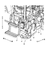
ここで、第2の排ガス処理部32は、支持部材40に支持されることで、ボンネット6の左側の外部に配置されている。以下では、図6を参照して支持部材40の構成について説明する。図6は、支持部材40を示す斜視図である。なお、図6では、支持部材40から第2の排ガス処理部32やパイプ34を取り外した状態を示している。図6に示すように、支持部材(支持ブラケット)40は、第2の排ガス処理部32が載置される板状の底部41を有している。底部41は、左右に長い板状に形成されている。また、底部41は、機体フレーム12のキャビン15を支持する部分(以下、この部分を「機体フレーム12a」と表記する)の前方へ突出し、かつ、第2の排ガス処理部32が昇降ステップ21の前方で左右いずれか(本実施形態では、右側)へ片寄せて載置されるように配置されている。
Here, the second exhaust
すなわち、底部41には、ボンネット6から見た外方側の半部(本実施形態では、右半部)に片寄せて第2の排ガス処理部32が載置される。また、底部41には、ボンネット6から見た内方側の半部(本実施形態では、左半部)に片寄せてパイプ34の第2の排ガス処理部32との接続端部35(図5参照)が配置される。支持部材40は、パイプ34が配置される左半部にパイプ34の接続端部35を覆う被覆部42を有している。被覆部42は、底部41にパイプ34の接続端部35が配置された場合に、接続端部35の周囲に隙間が形成される程度の径の穴が設けられている。これにより、パイプ34が露出しないため、車両の美観を高めることができる。また、底部41には、パイプ34の接続端部35が配置される位置に開口43が設けられている。また、支持部材40は、底部41が機体フレーム12aに固定され、被覆部42がキャビン15の下部からL字状の固定部材(ゴムマウント)44によって吊下げ固定されている。さらに、支持部材40は、鋳物で一体的に形成されることが好ましい。これにより、美観を高めることができる。さらに、支持部材40が鋳物で一体的であることに加えて、底部41が平坦であることから、第2の排ガス処理部32およびパイプ34を保護することができる他、圃場の作物を傷つけることを防止することができる。
That is, the second exhaust
このようなトラクタ1の構成によれば、支持部材40が第2の排ガス処理部32を下方から支持するため、第2の排ガス処理部32を適切な支持強度で支持することができる。これにより、第2の排ガス処理部32の支持性能を良好にすることができる。また、簡素な構成であるため、支持部材40を安価に得ることができる。さらに、第2の排ガス処理部32が機体2から左右いずれか(右側)に離れて配置されることで、操縦席10からキャビン15の左右(右側)下部が見えやすくなり、操縦席10からの視認性を良好にすることができる。
According to such a configuration of the tractor 1, since the
また、支持部材40に配置されるパイプ34の熱が開口43から支持部材40の外部へ放出されるため、支持部材40に熱がこもることを防止することができる。さらに、支持部材40にゴミなどが堆積することを防止することができる。
Further, since the heat of the
また、第2の排ガス処理部32は、支持部材40の底部41によって下方から支持されるとともに、底部41から延出している固定プレート45によって上部が固定されている(図3参照)。これにより、第2の排ガス処理部32を強固に保持することができる。なお、第2の排ガス処理部32では、固定プレート45に上部を固定させるために、後述するカバー33の上面のフランジ部分を上方へ延長している。
The second exhaust
また、上述したように、第2の排ガス処理部32には、外周面を覆うカバー33として熱遮板(以下、カバーを「熱遮板」という)が設けられている。熱遮板33には、複数の通気穴33aが設けられている。通気穴33aは、熱遮板33における第2の排ガス処理部32の前方に配置された前輪4(図1参照)と対向する側とは反対側の面(熱遮板33の後側の面)に設けられている。すなわち、熱遮板33の前側の面には通気穴33aを設けないことが好ましい。なお、通気穴33aは、熱遮板33の前輪4から見て対面する範囲を避けていればよい。したがって、たとえば、熱遮板33が前輪4から見て左右いずれかにずれて配置されている場合、通気穴33aを設けない範囲は、熱遮板33が前輪4の一直線上にある場合よりも左右いずれかへずれるようになる。また、通気穴33aは、円筒状の熱遮板33の周面全体における後側の3分の2程度の範囲に設けられることが好ましい。
In addition, as described above, the second exhaust
このようなトラクタ1の構成によれば、熱遮板33に覆われた第2の排ガス処理部32の放熱性を良好にすることができる。また、熱遮板33に通気穴33aが設けられていても、前輪4(図1参照)側から飛んできた泥などが通気穴33aから中に入ることを抑えることができる。
According to such a configuration of the tractor 1, the heat dissipation of the second exhaust
次に、図7および図8を参照して機体2に配置されている燃料タンク16および尿素水タンク17について説明する。図7は、燃料タンク16および尿素水タンク17を示す斜視図である。図8は、燃料サブタンク60を示す斜視図である。図7に示すように、機体2の左右における支持部材40を備える側の反対側には、尿素水タンク17が設けられている。尿素水タンク17は、エンジン7との間に設けられたローダブラケット36に固定されている。これにより、尿素水タンク17を簡素な構造で配置することができ、製造にかかるコストを安価にすることができる。また、機体2の左側には、尿素水タンク17と前後に並んで燃料タンク16が設けられている。尿素水タンク17の供給口17aと燃料タンク16の供給口16aとは、前後に並列して設けられている。なお、燃料タンク16は、機体2(キャビン15)の下方で左右に延伸して設けられている。また、キャビン15の左右いずれか(左側)の外部において、尿素水タンク17は、燃料タンク16の前側に配置されている。これにより、尿素SCRシステムを搭載したタイプのトラクタを容易に構成することができる。
Next, the
図8に示すように、機体2(キャビン15)の左右いずれか(本実施形態では、右側)の外部には、燃料タンク16とは別系統でエンジン7(図3参照)に燃料を供給する燃料サブタンク60が設けられている。燃料サブタンク60は、キャビン15の左右の外部に設けられた昇降ステップ21(図3参照)のうち一方を取り外して設けられる。この場合、オペレータは、キャビン15の左右における反対側の昇降ステップ21を使用して乗り降りする。なお、燃料サブタンク60は、燃料タンク16に接続されて、燃料タンク16からエンジン7に燃料を供給するようにしてもよい。この場合、燃料サブタンク60は、キャビン15の下方で燃料タンク16に近接して配置されることが好ましい。
As shown in FIG. 8, fuel is supplied to the engine 7 (see FIG. 3) separately from the
このようなトラクタ1の構成によれば、燃料サブタンク60を備えることで、燃料の総量を増やすことができ、作業可能な時間を延長することができる。また、簡素な構成で燃料を増やすことができる。
According to such a configuration of the tractor 1, by providing the
なお、2つの燃料タンク(燃料タンク16および燃料サブタンク60)の高さが異なる場合は、燃料漏れが発生することがあり、燃料漏れに対する品質確保が容易ではない。このため、燃料サブタンク60は、燃料タンク16と同等高さとなるように配置されることが好ましい。これにより、燃料漏れに対する品質確保が容易となる。また、各タンク16,60の高さが同等であることで、燃料の残量管理が容易となる。
In addition, when the heights of the two fuel tanks (the
また、燃料サブタンク60は、燃料タンク16に対して2本以上のホースで接続されることが好ましい。これにより、燃料サブタンク60と燃料タンク16との間の流動性を確保することができる。また、燃料サブタンク60と燃料タンク16とを接続するホースに逆止弁が設けられてもよい。これにより、燃料サブタンク60と燃料タンク16との間で、燃料タンク16から燃料が逆流することを防止することができる。
The
なお、本実施形態では、キャビン15の前方には、フロントローダに用いる油圧の取出口として、上述したアダプタ38が設けられている。また、本実施形態では、キャビン15の下方に設けられた燃料タンク16(図2参照)の支持ブラケット55を油圧ホース50のカバーにも兼用している。これらの構成によれば、フロントローダに対する油圧ホース50の配索を容易に行うことができる。
In the present embodiment, the above-described
次に、図9を参照して尿素水タンク17から第2の排ガス処理部32に尿素水を供給する尿素水ポンプ65について説明する。図9は、尿素水ポンプ65を示す斜視図である。図9に示すように、尿素水ポンプ(サプライポンプ)65は、キャビン15の下方、昇降ステップ21の内方側に設けられるとともに、第2の排ガス処理部32に対して近接して設けられている。これにより、スペースを有効利用することができる。そして、機体2を大型化させることもないため、製造にかかるコストを安価にすることができる。
Next, the
また、尿素水ポンプ65には、板状のポンプカバー(サプライカバー)66が取り付けられている。ポンプカバー66は、たとえば、金属製であり、尿素水ポンプ65の少なくとも外部に露出している正面および上面を覆うようにL字状に屈曲形成されている。これにより、尿素水ポンプ65に泥などが付着することを防止することができるとともに、金属製であることで、尿素水ポンプ65の冷却効果を高めることができる。また、尿素水ポンプ65がポンプカバー66に隠されることで、車両の美観を高めることができる。なお、ポンプカバー66は、尿素ポンプ65の他に、油圧ホース50やジョイスティックバルブ51なども覆うように形成されている。以下では、尿素水ポンプ65、油圧ホース50およびジョイスティックバルブ51などの各種の供給に関する構成部品を「サプライモジュール」と総称する場合がある。
Further, a plate-shaped pump cover (supply cover) 66 is attached to the
また、尿素水ポンプ65のポンプカバー66には、スリット状の複数の通気穴67が設けられている。これにより、尿素水ポンプ65の熱を外部へ逃がすことができる。これにより、尿素水ポンプ65の冷却効果を高めることができる。また、意匠的にも見栄えがよいため、車両の美観を高めることができる。
The pump cover 66 of the
さらなる効果や変形例は、当業者によって容易に導き出すことができる。このため、本発明のより広範な態様は、以上のように表しかつ記述した特定の詳細および代表的な実施形態に限定されるものではない。したがって、添付の特許請求の範囲およびその均等物によって定義される総括的な発明の概念の精神または範囲から逸脱することなく、様々な変更が可能である。 Further effects and modifications can be easily derived by those skilled in the art. Thus, the broader aspects of the present invention are not limited to the specific details and representative embodiments shown and described above. Accordingly, various modifications can be made without departing from the spirit or scope of the general inventive concept as defined by the appended claims and their equivalents.
1 作業車両(トラクタ)
2 機体
3 PTO出力軸
4 前輪
5 後輪
6 ボンネット
7 エンジン
8 ミッションケース
9 ダッシュパネル
10 操縦席
11 フェンダ
12 機体フレーム
12a (キャビンを支持する)機体フレーム
13 ステアリングハンドル
14 ハンドルポスト
15 キャビン
16 燃料タンク
16a 供給口
17 尿素水タンク
17a 供給口
20 クラッチペダル
21 昇降ステップ
22 マフラー
30 排ガス処理機構
31 第1の排ガス処理部(DOC)
32 第2の排ガス処理部(SCR)
33 カバー(熱遮板)
33a 通気穴
34 パイプ(テールパイプ)
35 接続端部
36 フロントローダブラケット
37 カラー部材
38 アダプタ
40 支持部材(支持ブラケット)
41 底部
42 被覆部
43 開口
44 固定部材(ゴムマウント)
45 固定プレート
50 油圧ホース
51 ジョイスティックバルブ
55 支持ブラケット
60 燃料サブタンク
65 尿素水ポンプ(サプライポンプ)
66 ポンプカバー(サプライカバー)
67 通気穴
1 Work vehicle (tractor)
2
32 Second exhaust gas treatment unit (SCR)
33 Cover (heat shield)
35
41
45
66 Pump cover (Supply cover)
67 Vent hole
Claims (4)
操縦席を取り囲むキャビンの左右の少なくともいずれかの外部に設けられた昇降ステップと、
前記キャビンを支持する機体フレームから前方へ突出するとともに前記第2の排ガス処理部が前記昇降ステップの前方で左右いずれかの外方側へ片寄せて載置される板状の底部を有する支持部材と、
前記第1の排ガス処理部と前記第2の排ガス処理部との間を接続する排ガス用のパイプと
を備え、
前記パイプは、
前記支持部材の前記底部において前記第2の排ガス処理部が片寄せて載置される側とは反対側に接続端部が配置され、
前記支持部材の前記底部は、
前記接続端部と対応する位置に開口が設けられることを特徴とするトラクタ。 The engine includes a first exhaust gas processing unit disposed above the engine inside the bonnet and a cylindrical second exhaust gas processing unit disposed upright on either the left or right side of the bonnet, and the engine An exhaust gas treatment mechanism for purifying the exhaust gas of
An elevating step provided outside at least one of the left and right sides of the cabin surrounding the cockpit,
A support member having a plate-like bottom portion that protrudes forward from the machine body frame that supports the cabin and on which the second exhaust gas treatment portion is placed on one side of the left or right in front of the lifting step. When,
A pipe for exhaust gas connecting between the first exhaust gas treatment unit and the second exhaust gas treatment unit;
With
The pipe is
A connection end is disposed on the opposite side of the bottom of the support member from the side on which the second exhaust gas treatment unit is placed side by side,
The bottom of the support member is
A tractor , wherein an opening is provided at a position corresponding to the connection end .
前記尿素水タンクは、前記キャビンの左右いずれかの外部において前記支持部材を備える側とは反対側に配置されること
を特徴とする請求項1に記載のトラクタ。 A urea water tank for storing urea water to be supplied to the second exhaust gas treatment unit for purifying the exhaust gas of the engine by selective catalytic reduction using urea water;
2. The tractor according to claim 1, wherein the urea water tank is disposed on a side opposite to a side including the support member on either the left or right side of the cabin.
前記燃料タンクは、
燃料の供給口が前記尿素水タンクの供給口と前後に並列して配置されること
を特徴とする請求項2に記載のトラクタ。 A fuel tank for storing fuel to be supplied to the engine;
The fuel tank is
The tractor according to claim 2, wherein a fuel supply port is arranged in parallel with the supply port of the urea water tank in front and rear.
尿素水ポンプ(65)は、前記第2の排ガス処理部(32)の後方に設けられたものであると共に、
前記尿素水ポンプ(65)は、キャビン(15)の下方で、かつ、前記昇降ステップ(21)の内方側に設けられていることを特徴とする請求項1から3のいずれか1項に記載のトラクタ。 A urea water pump (65) for supplying the urea water stored in the urea water tank (17) to the second exhaust gas treatment unit (32);
The urea water pump (65) is provided behind the second exhaust gas treatment section (32), and
The said urea water pump (65) is provided in the inward side of the said raising / lowering step (21) under the cabin (15), The any one of Claim 1 to 3 characterized by the above-mentioned. The described tractor.
Priority Applications (7)
| Application Number | Priority Date | Filing Date | Title |
|---|---|---|---|
| JP2015086254A JP6492921B2 (en) | 2015-04-20 | 2015-04-20 | Tractor |
| KR1020160030876A KR20160124659A (en) | 2015-04-20 | 2016-03-15 | Tractor |
| EP16162798.9A EP3085565B1 (en) | 2015-04-20 | 2016-03-30 | Tractor |
| US15/098,817 US9943805B2 (en) | 2015-04-20 | 2016-04-14 | Tractor |
| MYPI2016701403A MY176441A (en) | 2015-04-20 | 2016-04-18 | Tractor |
| AU2016202464A AU2016202464B2 (en) | 2015-04-20 | 2016-04-19 | Tractor |
| CN201610248162.6A CN106064561B (en) | 2015-04-20 | 2016-04-20 | Tractor |
Applications Claiming Priority (1)
| Application Number | Priority Date | Filing Date | Title |
|---|---|---|---|
| JP2015086254A JP6492921B2 (en) | 2015-04-20 | 2015-04-20 | Tractor |
Related Child Applications (1)
| Application Number | Title | Priority Date | Filing Date |
|---|---|---|---|
| JP2018236350A Division JP6624276B2 (en) | 2018-12-18 | 2018-12-18 | Tractor |
Publications (3)
| Publication Number | Publication Date |
|---|---|
| JP2016203752A JP2016203752A (en) | 2016-12-08 |
| JP2016203752A5 JP2016203752A5 (en) | 2019-01-10 |
| JP6492921B2 true JP6492921B2 (en) | 2019-04-03 |
Family
ID=55640640
Family Applications (1)
| Application Number | Title | Priority Date | Filing Date |
|---|---|---|---|
| JP2015086254A Active JP6492921B2 (en) | 2015-04-20 | 2015-04-20 | Tractor |
Country Status (7)
| Country | Link |
|---|---|
| US (1) | US9943805B2 (en) |
| EP (1) | EP3085565B1 (en) |
| JP (1) | JP6492921B2 (en) |
| KR (1) | KR20160124659A (en) |
| CN (1) | CN106064561B (en) |
| AU (1) | AU2016202464B2 (en) |
| MY (1) | MY176441A (en) |
Families Citing this family (5)
| Publication number | Priority date | Publication date | Assignee | Title |
|---|---|---|---|---|
| US10071626B2 (en) * | 2015-04-28 | 2018-09-11 | Cnh Industrial America Llc | Exhaust after-treatment mounting arrangement |
| KR102129405B1 (en) * | 2017-05-10 | 2020-07-03 | 에어클로아크 게엠베하 | Systems and methods for anonymized statistical database queries using noise elements |
| CN107493767A (en) * | 2017-09-06 | 2017-12-22 | 佛山宏发引力智能科技有限公司 | A kind of agricultural machinery seedling separation device |
| GB201915858D0 (en) * | 2019-10-31 | 2019-12-18 | Agco Int Gmbh | Exhaust after treatment cooling system |
| JP7152464B2 (en) * | 2020-12-08 | 2022-10-12 | ヤンマーパワーテクノロジー株式会社 | tractor |
Family Cites Families (14)
| Publication number | Priority date | Publication date | Assignee | Title |
|---|---|---|---|---|
| JP3714559B1 (en) * | 2004-11-05 | 2005-11-09 | 日産ディーゼル工業株式会社 | Exhaust purification device |
| JP4779926B2 (en) * | 2006-10-25 | 2011-09-28 | トヨタ自動車株式会社 | Exhaust system for internal combustion engine |
| US7937936B2 (en) | 2007-01-16 | 2011-05-10 | Deere & Company | Vehicle exhaust component arrangement |
| JP5102180B2 (en) | 2008-11-12 | 2012-12-19 | ヤンマー株式会社 | Engine device for work vehicle |
| GB2466483A (en) | 2008-12-19 | 2010-06-30 | Agco Gmbh & Co | A vertical exhaust system for a vehicle |
| GB0909987D0 (en) | 2009-06-11 | 2009-07-22 | Agco Sa | Catalytic converter module |
| US20120036833A1 (en) | 2010-08-11 | 2012-02-16 | Agco Corporation | Scavenging Vacuum Pressure Provisioning with Exhaust Treatment |
| JP5865040B2 (en) * | 2011-11-30 | 2016-02-17 | 株式会社クボタ | Work vehicle |
| JP5523529B2 (en) | 2012-09-26 | 2014-06-18 | ヤンマー株式会社 | Work vehicle |
| JP5478689B2 (en) | 2012-09-26 | 2014-04-23 | ヤンマー株式会社 | Engine device for work vehicle |
| JP2014159788A (en) * | 2013-02-20 | 2014-09-04 | Iseki & Co Ltd | Tractor |
| JP5956373B2 (en) * | 2013-03-28 | 2016-07-27 | ヤンマー株式会社 | Engine device for work vehicle |
| KR102138732B1 (en) * | 2013-04-26 | 2020-07-28 | 얀마 파워 테크놀로지 가부시키가이샤 | Work vehicle |
| JP6200682B2 (en) * | 2013-04-26 | 2017-09-20 | ヤンマー株式会社 | Tractor |
-
2015
- 2015-04-20 JP JP2015086254A patent/JP6492921B2/en active Active
-
2016
- 2016-03-15 KR KR1020160030876A patent/KR20160124659A/en not_active Application Discontinuation
- 2016-03-30 EP EP16162798.9A patent/EP3085565B1/en active Active
- 2016-04-14 US US15/098,817 patent/US9943805B2/en active Active
- 2016-04-18 MY MYPI2016701403A patent/MY176441A/en unknown
- 2016-04-19 AU AU2016202464A patent/AU2016202464B2/en not_active Ceased
- 2016-04-20 CN CN201610248162.6A patent/CN106064561B/en active Active
Also Published As
| Publication number | Publication date |
|---|---|
| AU2016202464A1 (en) | 2016-11-03 |
| CN106064561B (en) | 2019-05-10 |
| US9943805B2 (en) | 2018-04-17 |
| KR20160124659A (en) | 2016-10-28 |
| MY176441A (en) | 2020-08-10 |
| EP3085565B1 (en) | 2020-04-29 |
| EP3085565A1 (en) | 2016-10-26 |
| CN106064561A (en) | 2016-11-02 |
| US20160303511A1 (en) | 2016-10-20 |
| AU2016202464B2 (en) | 2017-11-23 |
| JP2016203752A (en) | 2016-12-08 |
Similar Documents
| Publication | Publication Date | Title |
|---|---|---|
| JP6492922B2 (en) | Tractor | |
| JP2016203753A5 (en) | ||
| JP6492921B2 (en) | Tractor | |
| JP5948894B2 (en) | Work vehicle | |
| JP2016203752A5 (en) | ||
| WO2018180028A1 (en) | Tractor | |
| WO2018180027A1 (en) | Tractor | |
| JP6575447B2 (en) | Work vehicle | |
| JP2022022274A (en) | Tractor | |
| JP6984691B2 (en) | Tractor | |
| JP6721031B2 (en) | Tractor | |
| JP7243792B2 (en) | tractor | |
| JP6624276B2 (en) | Tractor | |
| JP5987927B2 (en) | Work vehicle | |
| JP6531692B2 (en) | Work vehicle | |
| JP2017180207A (en) | Work vehicle | |
| JP2015131639A5 (en) | ||
| JP2020148203A (en) | Tractor |
Legal Events
| Date | Code | Title | Description |
|---|---|---|---|
| A621 | Written request for application examination |
Free format text: JAPANESE INTERMEDIATE CODE: A621 Effective date: 20180315 |
|
| A521 | Request for written amendment filed |
Free format text: JAPANESE INTERMEDIATE CODE: A523 Effective date: 20181126 |
|
| A871 | Explanation of circumstances concerning accelerated examination |
Free format text: JAPANESE INTERMEDIATE CODE: A871 Effective date: 20181126 |
|
| A975 | Report on accelerated examination |
Free format text: JAPANESE INTERMEDIATE CODE: A971005 Effective date: 20181128 |
|
| A131 | Notification of reasons for refusal |
Free format text: JAPANESE INTERMEDIATE CODE: A131 Effective date: 20181211 |
|
| A521 | Request for written amendment filed |
Free format text: JAPANESE INTERMEDIATE CODE: A523 Effective date: 20190108 |
|
| TRDD | Decision of grant or rejection written | ||
| A01 | Written decision to grant a patent or to grant a registration (utility model) |
Free format text: JAPANESE INTERMEDIATE CODE: A01 Effective date: 20190205 |
|
| A61 | First payment of annual fees (during grant procedure) |
Free format text: JAPANESE INTERMEDIATE CODE: A61 Effective date: 20190218 |
|
| R150 | Certificate of patent or registration of utility model |
Ref document number: 6492921 Country of ref document: JP Free format text: JAPANESE INTERMEDIATE CODE: R150 |